

Page 1

HITACHI
OPERATING GUIDE FOR
COLOUR MONITOR CPX1498MS
BEDIENUNGSANLEITUNG FÜR FARBMONITOR CPX1498MS
MODE D'EMPLOI DU MONITEUR COULEURS CPX1498MS
Page 2

Page 3
BEFORE OPERATING THIS EQUIPMENT
Mains Supply:
This equipment is designed to operate on 220-240V AC 50Hz only. Do not operate on
DC power supplies or other voltages. Before connecting to the mains, please read the
following instructions carefully.
ENGLISH
IMPORT
WORDING FOR CLASS 1 EQUIPMENT INSTRUCTION BOOKS AND LABELS
ANT FOR THE UNITED KINGDOM
The mains lead on this equipment is supplied with a moulded plug incorporating a fuse, the value
of which is indicated on the pin face of the plug. Should the fuse need to be replaced, an ASTA or
BSI approved BS 1362 of the same rating must be used. If the fuse cover is detachable, never
use the plug with the cover omitted. If a replacement fuse cover is required, ensure it is of the
same colour as that visible on the pin face of the plug. Fuse covers are available from your dealer.
DO NOT cut off the mains plug from this equipment. If the plug fitted is not suitable for the power
points in your home or the cable is too short to reach a power point, then use an appropriate safety
approved extension lead or consult your dealer.
Should it be necessary to change the mains plugs, this must be carried out by a competent
person, preferably a qualified electrician.
If there is no alternative to cutting off the mains plug, ensure that you dispose of it immediately,
having first removed the fuse, to avoid a possible shock hazard by inadvertent connection to the
mains supply.
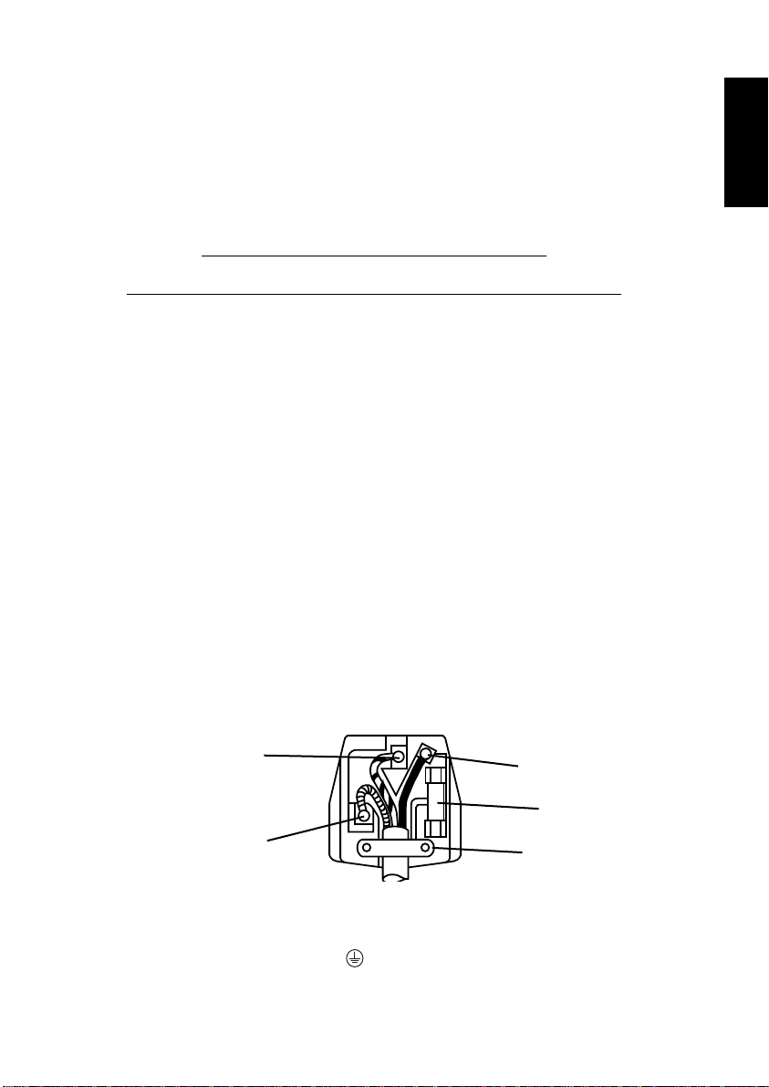
WARNING: THIS EQUIPMENT MUST BE EARTHED
IMPORTANT
The wires in the mains lead are coloured in accordance with the following code;
Green and Yellow= Earth, Blue = Neutral, Brown = Live
Green and
Yellow to Earth
Brown to Live
Fuse
Blue to Neutral
As these colours may not correspond with the coloured markings identifying the terminals in your plug,
proceed as follows:
The wire which is coloured GREEN and YELLOW must be connected to the terminal in the plug which is
marked with the letter E or by the EARTH symbol or coloured GREEN or GREEN and YELLOW. The
wire coloured BLUE must be connected to the terminal with the letter N or coloured BLUE or BLACK. The wire
coloured BROWN must be connected to the terminal marked with the letter L or coloured BROWN or RED.
Cord Clamp
E
3
Page 4
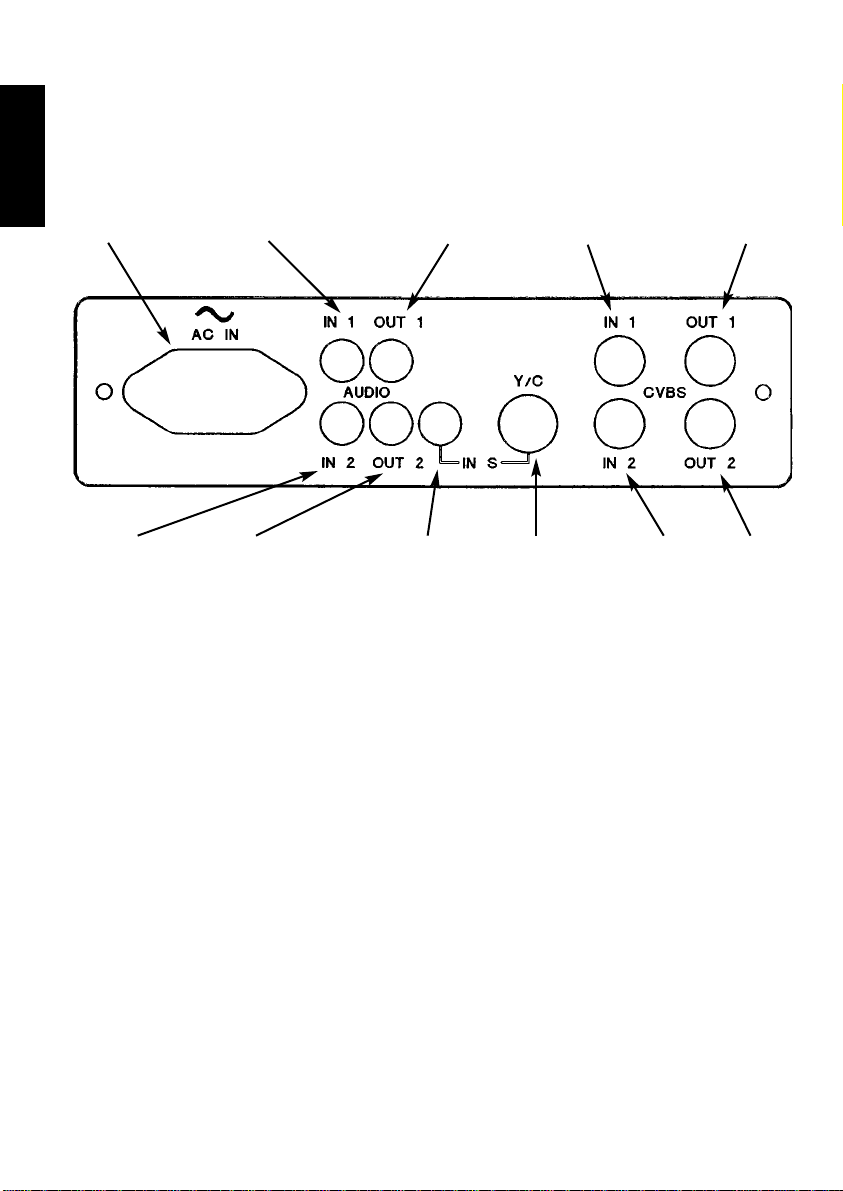
SET-UP INSTRUCTIONS
Connect your equipment to the desired sockets of this monitor
REAR VIEW
ENGLISH
AUDIO-IN 1A.C. INPUT AUDIO-OUT 1 VIDEO-IN 1 VIDEO-OUT 1
AUDIO-IN 2 S-VHS
OUTPUT SIGNALS
If desired, the signal inputs to the Video-in and Audio-in sockets can also be
input to other equipment, such as a VCR. Simply connect VCR to the Video-out
and Audio-out sockets, using suitable connecting leads. Please refer to your
VCR operating guide for further instructions. The Video-out sockets have a 75 Ω
termination resistor which is automatically disconnected when a connection is
made to them.
AUDIO-OUT 2 AUDIO-IN
S-VHS
SOCKET
VIDEO-
IN 2
VIDEO-
OUT 2
4
Page 5
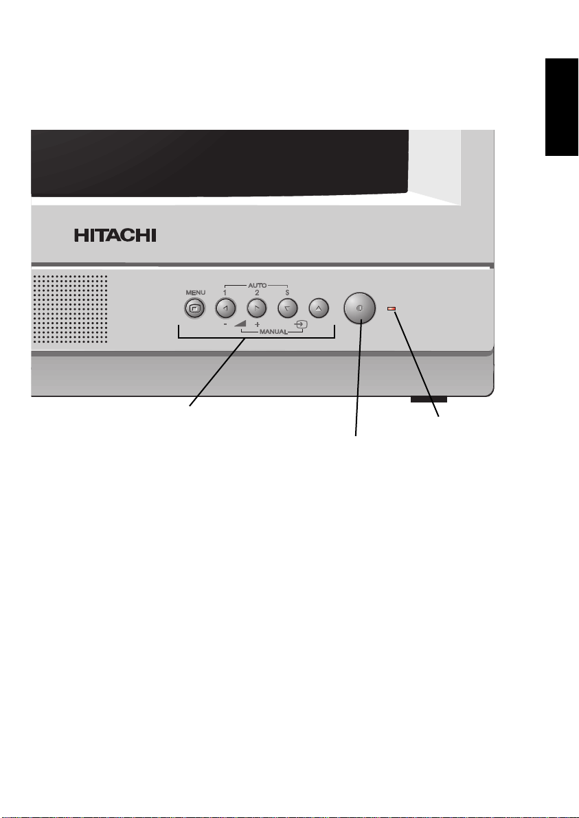
Switch on monitor and equipment. The red LED indicator on the front of the
monitor will light.
ENGLISH
Control buttons
LED
ON/OFF
Control of monitor
All control for this monitor other than on/off is via the five front control buttons,
MENU 7 3 1 5, using these buttons will allow you to navigate your way around
the `on screen displays` (OSD) built into this monitor.
5
Page 6

ON SCREEN DISPLAY (OSD) MENU STRUCTURE
ENGLISH
MAIN MENU
INPUT SELECT MANUAL
VOLUME 30
PICTURE SETUP
OPTIONS SETUP
LANGUAGE ENGLISH
Select
MENU
Exit
Volume Menu
VOLUME 31
User Selection
MANUAL, AUTO
0-63
ENGLISH, GERMAN, FRENCH, SPANISH,
DUTCH, ITALIAN, SYMBOL
6
Page 7

PICTURE/SETUP
BRIGHTNESS 21
CONTRAST 30
COLOUR 16
HUE 14
SHARPNESS 18
OSD BACKGROUND NO
Select
MENU
Exit
User Selection
0-63
0-63
0-63
0-63
0-63
YES/NO
ENGLISH
OPTIONS SETUP
AV INPUTS 12S
DWELL (s) 5
NAMES SETUP
OSD MODE AUTO
Select
MENU
Exit
NAMES SETUP
INPUT 3
NAME AISLE
Select
MENU
Exit
User Selection
12S, 1-S and any other
combination 5 to 300 (sec)
OFF, AUTO, PERMANENT
1, 2, 3, SVHS
16 ALFA NUMERICS
7
Page 8

Volume adjustment
Volume adjustment (manual only)
In “manual” to increase or decrease the volume level temporarily, simply press
button to decrease the level and press 3button to increase the level. Pressing
ENGLISH
either of these buttons will display the “volume menu” on the screen.
Volume adjustment (auto) and to store a volume level
To ensure that the volume level will always return to your preferred setting from
switch on or when adjusting volume level, (the only way to adjust in AUTO mode),
follow this procedure: -
a. Press the MENU button once and the “main menu” will then appear on the
screen as shown with the
function is available for adjustment).
b. Press the 5 button once. The
c. Press the
personal preference.
d. The menu will stay on the screen for 20 seconds if no other operation is applied
or you can press MENU button again and the menu will disappear. The new
settings are now stored automatically.
Picture adjustments
a. Press the MENU button once and the “main menu” will then appear on the
screen as shown with the
function is available for adjustment)
b. Press the 5 button twice. The
c. Press the
In “Picture set-up” menu : a. The
adjustment).
b. Press the
personal preference.
c. Press the 5 button once. The
d. Press the
personal preference.
e. Repeat this procedure for the colour, hue (NTSC only) and sharpness.
f. The menu will stay on the screen for 20 seconds if no other operation is applied
or you can press MENU button again and the menu will disappear. The new
settings are now stored automatically.
7 or 3 buttons to decrease or increase volume level to suit your
7 or 3 buttons to change to the “Picture set-up” menu.
brightness line
will now be blue (indicating that this function is available for
7 or 3 buttons to decrease or increase brightness level to suit your
7 or 3 buttons to decrease or increase contrast level to suit your
input select line
volume line
input select line
picture line
contrast line
coloured blue (indicating that this
will now become blue.
coloured blue (indicating that this
will now become blue.
will now become blue.
7
8
Page 9

Input select, Selection of video and audio inputs
a. Press the MENU button once and the “main menu” will then appear on the
screen as shown with the
function is available for adjustment).
b. Press the 7 or 3 buttons to show either “auto” or “manual”.
Manual
Once selected “manual” mode : -
a. The menu will stay on the screen for 20 seconds if no other operation is applied
or you can press MENU button again and the menu will disappear. The new
settings are now stored automatically.
Manual input selection
To select the various inputs : -
a. Press the 1 or 5 buttons to cycle through the various inputs in either direction.
Auto
In “auto” mode the display will sequence and wrap around through all the
available inputs. The time that each input is displayed before the sequence
continues (dwell time) is by the following procedure whilst in “main menu” : a. Press the 5 button three times. The
b. Press the
In “Options set-up” menu : a. The
adjustment).
b. Press the 5 button once. The
c. Press the
d. The menu will stay on the screen for 20 seconds if no other operation is applied
or you can press MENU button again and the menu will disappear. The new
settings are now stored automatically.
7 or 3 buttons to change to the “Option set-up” menu.
AV input line
will now be blue (indicating that this function is available for
7 or 3 buttons to change the timing between 5 and 300 seconds
input select line
options line
dwell line
will now become blue.
coloured blue (indicating that this
will now become blue.
ENGLISH
Auto override
To select the various inputs and suspend the auto function : a. Press the buttons 1, 2, or S to select and hold inputs 1, 2 or S respectively. For
each selection “HOLD” will be displayed.
b. Another input can be held whilst the display is on alternative
c. To remove “hold” and resume operation press the button that was selected for
hold.
9
Page 10

Option selection
a. Press the MENU button once and the “main menu” will then appear on the
screen as shown with the
function is available for adjustment).
b. Press the 5 button three times. The
ENGLISH
c. Press the
In “Options set-up” menu : -
a. The
adjustment).
b. Press the 7 or 3 buttons to change to the video/audio inputs options required
i.e. 12S, -2S, 1-S, 12-, 1--, -2-, --S
For reference: 1 refers to input 1, 2 refers to input 2 and S refers to the SVHS
input.
c. The menu will stay on the screen for 20 seconds if no other operation is applied
or you can press MENU button again and the menu will disappear. The new
settings are now stored automatically.
Language selection
a. Press the MENU button once and the “main menu” will then appear on the
screen as shown with the
function is available for adjustment).
b. Press the 5 button four times. The
c. Press the
i.e. English, German, Spanish, Dutch, Italian and Symbol.
d. The menu will stay on the screen for 20 seconds if no other operation is applied
or you can press MENU button again and the menu will disappear. The new
settings are now stored automatically.
7 or 3 buttons to change to the “Option set-up” menu.
AV input line
will now be blue (indicating that this function is available for
7 or 3 buttons to change to the alternative language options required
input select line
options line
input select line
language line
coloured blue (indicating that this
will now become blue.
coloured blue (indicating that this
will now become blue.
OSD background
a. Press the MENU button once and the “main menu” will then appear on the
screen as shown with the
function is available for adjustment).
b. Press the 5 button twice. The
c. Press the
In “Picture set-up” menu : a. The
adjustment).
b. Press the 5 button five times. The
c. Press the
10
7 or 3 buttons to change to the “Picture set-up” menu.
brightness line
will now be blue (indicating that this function is available for
7 or 3 buttons to switch on or off the OSD background.
input select line
picture line
OSD mode line
coloured blue (indicating that this
will now become blue.
will now become blue.
Page 11

d. The menu will stay on the screen for 20 seconds if no other operation is applied
or you can press MENU button again and the menu will disappear. The new
settings are now stored automatically.
OSD mode
a. Press the MENU button once and the “main menu” will then appear on the
screen as shown with the
function is available for adjustment).
b. Press the 5 button twice. The
c. Press the
the OSD to be on for a few seconds after any display change or on
permanently.
d. The menu will stay on the screen for 20 seconds if no other operation is applied
or you can press MENU button again and the menu will disappear. The new
settings are now stored automatically.
Names
a. Press the MENU button once and the “main menu” will then appear on the
screen as shown with the
function is available for adjustment).
b. Press the 5 button three times. The
c. Press the
In “Options set-up” menu : a. The
adjustment).
b. Press the 5 button twice. The
c. Press the
In “Names set-up” menu : a. The
adjustment).
b. Press the 7 or 3 buttons to select the input you wish to name. Once selected.
c. Press the 1 or 5 button once. The
d. Press the
e. Press the 1 or 5 buttons to select the relevant character you wish to display.
Once selected.
f. Press the
g. Press the 1 or 5 buttons to select the relevant character you wish to display.
Once selected.
h. Press the
7 or 3 buttons to show either “off”, “auto” or “permanent”.This allows
7 or 3 buttons to change to the “Option set-up” menu.
AV input line
will now be blue (indicating that this function is available for
7 or 3 buttons to change to the “Names set-up” menu.
Input line
will now be blue (indicating that this function is available for
7 or 3 buttons to highlight first position.
7 or 3 buttons to highlight second position.
7 or 3 buttons to highlight third position.
input select line
OSD mode line
input select line
options line
names line
name line
coloured blue (indicating that this
will now become blue.
coloured blue (indicating that this
will now become blue.
will now become blue.
will now become blue.
ENGLISH
11
Page 12

i. Repeat this procedure for all the remaining characters that you require up to 16
characters.
Once selected.
j. The menu will stay on the screen for 40 seconds if no other operation is applied
ENGLISH
or you can press MENU button twice and the menu will disappear. The new
settings are now stored automatically.
No sync
This is displayed in the middle of the screen when there is no sync or video on the
selected input.
LED flashing
In the unlikely event that the LED flashes when the controls are not being used a
fault has occurred.
12
Page 13

SPECIFICATIONS
Picture Tube.........................................................34cm Type A34EACO1X06
Mains Voltage.......................................................220 - 240V AC 50 Hz
Power Consumption.............................................38 Watts
Speaker................................................................8 Ω
Dimensions (W x H x D) cm .................................37 x 35.5 x 38.5
Weight ..................................................................8.8 kg
EXTERNAL CONNECTORS
S-VHS SOCKET
1
2
ENGLISH
3
4
5
PIN NO. FUNCTIONS VOLTAGE LEVEL PEAK-PEAK
1 Chrominance input 0V7 above blanking at 75Ω impedance
2 Luminance input 1V0 at 75Ω impedance
3 Chrominance ground
4 Luminance ground
5 Frame ground
PHONO CONNECTORS
Audio Output....0V5 nominal level
Audio in
BNC CONNECTIONS
Audio out
Video in
.........................0V2 minimum
.........................2V0 maximum at an impedance of less than 1KΩ.
Audio Input ......0V5 nominal level
.........................2V0 maximum at an impedance of 10KΩ or more.
Video Input............1V0 peak-peak at 75Ω impedance
Video out
Video Output.........1V0 peak-peak at 75Ω impedance
13
Page 14

Guarantee
Your guarantee
of Excellence
ENGLISH
Thank you for purchasing this monitor
In the unlikely event that this product should develop a fault, we
undertake to replace or repair any part of the product which fails due to a
manufacturing defect within 3 years of the date of purchase provided that:
i) The product has been installed and used only in accordance with the
instructions supplied with the product.
ii) The product has not been repaired, maintained, or modified by any
person other than an Hitachi authorised engineer.
iii) The product serial number has not been removed or altered.
This guarantee does not apply to product acquired secondhand or the
adjustment of user controls.
Any parts replaced under this guarantee shall become the property of
Hitachi Home Electronics (Europe) Ltd.
Please note that evidence of the date of purchase will be required before
any service under this guarantee is carried out.
This guarantee does not affect your statutory rights.
In all cases of difficulty please consult your Hitachi dealer.
14
Page 15

Page 16

a
c
h
, d
International Sales Division
THE HITACHI ATAGO BUILDING
Nº15 - 12 Nishi Shinbashi, 2 - Chome
Minato-Ku, Tokyo 105, Japan
Tel. 3 32581111
HITACHI HOME ELECTRONICS (EUROPE) Ltd, Hitachi House, Station Road, Hayes, Middlesex,
UNITED KINGDOM, UB3 4DR, Tel: 0181 8492000
HITACHI SALES EUROPA GmbH, Am Seestern 18,
40547 Düsseldorf, DEUTSCHLAND, Tel: 0211 529150
HITACHI SALES ITALIANA SPA, Via Gulli n.39,
20147 Milano, ITALIA, Tel: 0039 - 02 487861
HITACHI HOME ELECTRONICS (HELAS)
S.A. 91Falirou Street, 117-41 Athens,
GREECE, Tel: 01-924-2620
HITACHI SALES IBERICA, S.A., Gran Via Carlos
Tercero. 101,1-1, Barcelona 08028,
ESPAÑA, Tel: +34 93 409 25 50
HITACHI FRANCE (RADIO TV ELECTROME-
NAGERS) S.A., 4 Allée des Sorbiers, Parc d’activité du
Chêne,BP 45, 69671 Bron cedex, FRANCE,
Tel: (33) 04-72-14-29-70
HITACHI HOME ELECTRONICS NORWAY, Brugata 14, N-0186
Oslo, NORGE, Tel: +47 9 2205 9060
HITACHI HOME ELECTRONICS (NORDIC) AB, Haukadalsgatan 10,
164 94 Kista, SVERIGA,Tel: +46 8 562 711 00
ITEM N.V./S.A.(INTERNATIONAL TRADE FOR ELECTRONIC MATERIAL & MEDIA
N.V./S.A.),UCO Tower Bellevue, 17-9050 Gent, BELGIQUE (for BENELUX) Tel: (32)09 230 4801
...all around the world
Box 77,
 Loading...