

Page 1
Packed in a temporarily assembled condition
Hitachi Plasma Display Ceiling Mount Unit
Model
CMPAT04 Installation Instructions
Thank you for purchasing the Hitachi Plasma Display Ceiling Mount Unit.
To ensure correct usage, please read this instruction manual thoroughly. After reading, please store this manual
in a safe place for future reference.
This plasma display ceiling mount unit is for use only with the following models :
CMP401X, CMP402HD, CMP307X
♦ Special techniques are necessary for installation of
the plasma display.
Do not attempt to perform this work by yourself.
♦ Request an installation specialist to install this unit.
♦ This company assumes absolutely no responsibility
for injuries and damages that may occur due to
improper installation and handling.
• To dealers and shops
• To ensure customer safety, be sure to design the
installation location so that the strength is sufficient
to withstand the weight of both the plasma display
and the Ceiling mount unit.
• Always use at least two persons for all
installations.
• Firmly install coupling pins, snap pins and screws
as specified in the installation instructions.
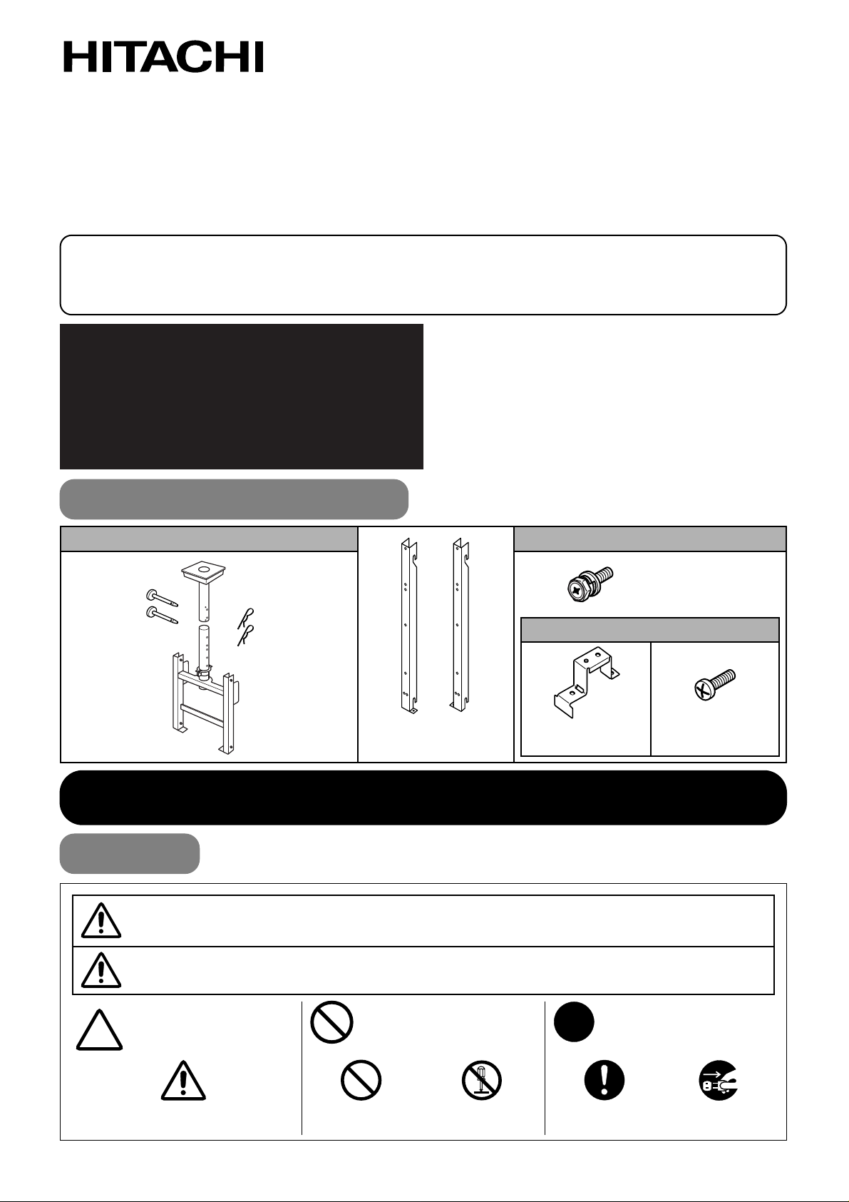
Parts Configuration Chart
In the parts packing
Parts for CMP401X only
Coupling pin
X
2
Usage cautions to ensure correct usage
• The following symbols are used to ensure safe usage of the product, to prevent danger to
yourself and other parties and to prevent damage to property.
Symbols
♦ This symbol indicates that incorrect handling due to ignoring this symbol
can result in the possibility of personal injury or even death.
♦This symbol indicates
additional cautions
(including warnings).
♦ This symbol indicates that incorrect handling due to ignoring this symbol
can result in the possibility of personal injury and physical damage.
♦This symbol indicates
forbidden actions.
♦This symbol indicates
required actions.
Ceiling mount unit
X
1
Snap pin
X
2
Angle
adjustment unit
X
1
(left) (right)
Display mount fitting
1 each left/right
M6
X
18 screw
X
8
Support
X
2
M4 x 12 screw
X
4
WARNING
CAUTION
Caution
(general)
Forbidden
(general)
Required
(general)
Disassembly
prohibited
Indicates that the power
plug is to be disconnected
from the power outlet.
Page 2
- 2 -
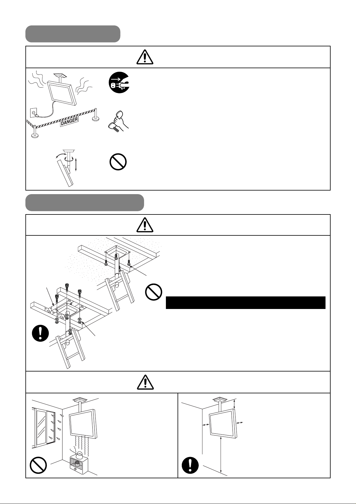
Safety Cautions
♦ When a malfunction occurs, disconnect the power plug
from the power outlet and take measures to prevent
other people coming near the plasma display.
In the cases such as
• The plasma display is loose and vibrates to an extreme degree,
• Mounting screws or parts are loose or missing,
failure to take appropriate actions can result in injury.
Perform the following actions immediately whenever a
malfunction occurs.
1.Turn off the plasma display power switch.
2.Disconnect the power plug from the power outlet.
3.
Surround the area with rope, etc., to prevent other people coming near.
4.Contact your local dealer.
♦
Ask your dealer to install, move or adjust the angle
of the ceiling mount unit.
Incorrect installation or adjustment can cause the plasma display
to fall.
♦
The ceiling where the ceiling mount unit is to
be installed must fully support the weight of
the plasma display and the ceiling mount unit
for an extended period of time.
Take measures to fully withstand earthquake,
other vibration and external forces.
Incorrect installation can cause the plasma display to fall
and cause injury.
Total load of the (plasma display + ceiling mount unit) = 51kg
• Always use bolts, washers and nuts to firmly install on a
rigid construction member such as ceiling beam, etc.
• Do not mount directly on a ceiling of insufficient strength or
use wood screws or anchor screws that do not have
sufficient strength to reliably resist pulling out.
• When installing the ceiling mount unit on ceiling
construction members, use commercially available 10mm
nominal diameter screws that are appropriate for the
construction members.
10cm
or more
10cm
or more
10cm
or more
10cm
or more
♦
Avoid installing in
locations where the
temperature and
humidity are
excessively high,
and where contact
with water is
possible.
These can result in fire
or electrical shock.
♦
Do not block the
ventilation holes.
Also provide
sufficient clearance
in regard to the
surroundings to
avoid blocking the
ventilation.
The internal temperature
could elevate and
possibly result in fire.
Installation Location
Wood screw
Ceiling beam
10mm nominal dia.
bolt, spring washer,
washer, nut (4 each)
Contact your
local dealer.
Disconnect the
power plug from
the power outlet.
Handling by other than
professional contractors
is prohibited.
WARNING
WARNING
CAUTION
Page 3
- 3 -
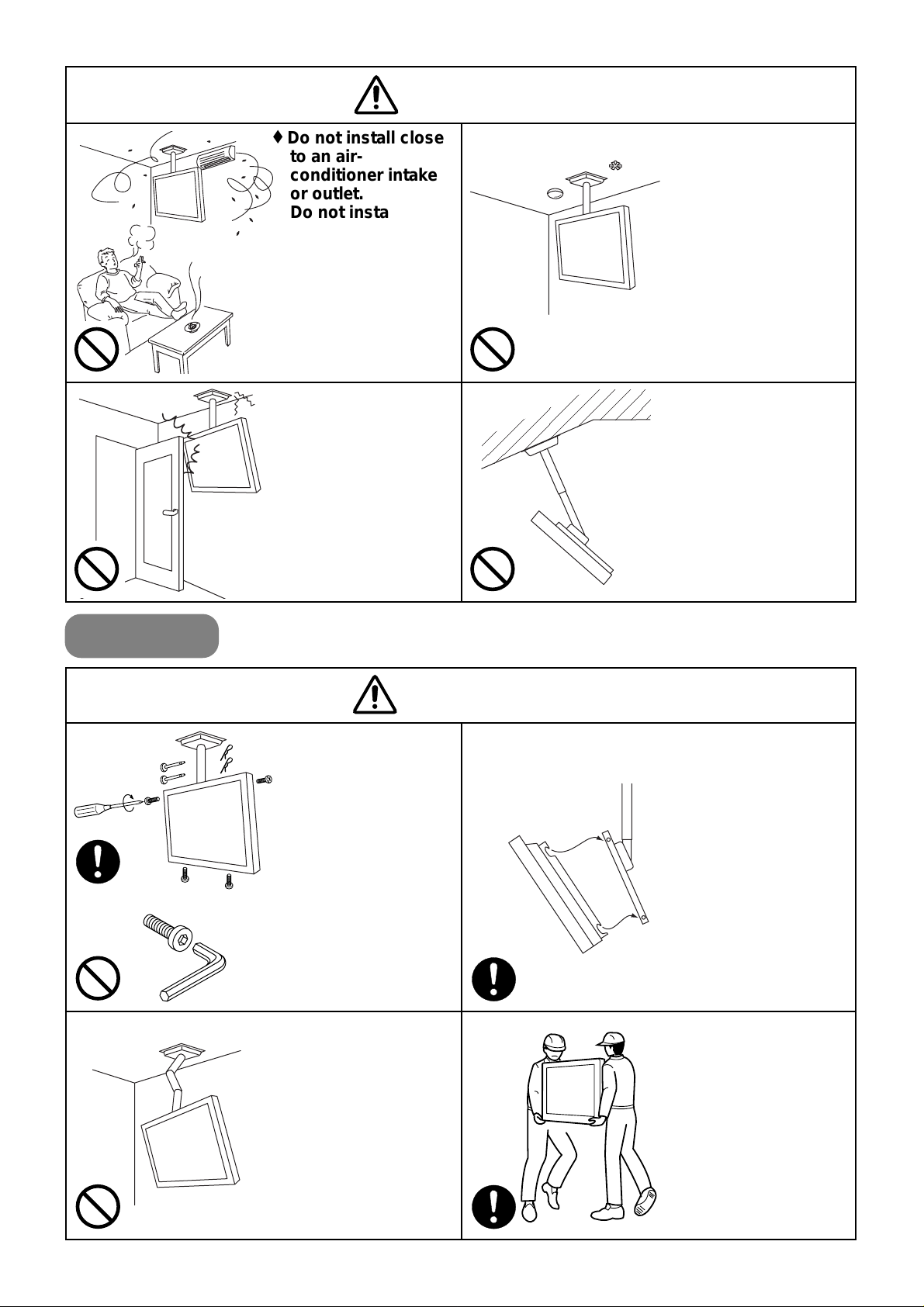
Installing
♦
Do not install close
to an airconditioner intake
or outlet.
Do not install in
locations where
there is excessive
amounts of dust,
oily smoke or
tobacco smoke.
Fire could result.
♦
Do not install in
locations where
there is excessive
vibration or impact.
Injury and damage
could result from
falling.
♦
Do not install near
sprinklers or
sensors.
This could result in
misoperation or
electrical shock.
♦
Install only on a
horizontal surface.
Avoid sloped
surfaces. Also, do not
install facing upward.
The internal
temperature could
elevate and possibly
result in fire.
Injury or damage could
also result from falling.
CAUTION
WARNING
♦
Make sure the
plasma display
mount fittings and
angle adjustment
unit are firmly
engaged.
Failure to do so could
cause the plasma
display to fall.
♦
Do not alter any of
the parts. And do
not use broken
parts.
This could result in
injury due to the
plasma display falling.
♦
Always use at least
two people to
perform the
installation work.
Injury could result from
dropping heavy
objects.
♦
Firmly install
coupling pins, snap
pins and screws in
the prescribed
locations.
Failure to do so could
result in the plasma
display dropping.
♦ Do not loosen or
remove hex head
screws.
This could result in
insecure installation
and dropping.
Page 4

- 4 -
Installation Method
Installation space
While referring to the dimensional drawing for the ceiling mount unit, decide an installation location where the
ceiling strength is sufficient. Also, set the height adjustment position, screen tilt angle and horizontal angle of the
ceiling mount unit beforehand.
CMP401X
CMP402HD
549
45 45
418549
(307)
25
(121)
940
97 55
366
742 235 180 (P60x3)
977
583
45 45
451583
(274)
25
(121)
1041
89 55
319
648 314 180 (P60x3)
969
Screen
center
Screen
center
Page 5

- 5 -
513
45 45
398513
884
337
684
291 180 (P60 x 3)
100
55
975
(284)
25
(121)
CMP307X
Screen
center
Ceiling mount unit dimensions
330
300
Pipe dia.
61mm
Four 12mm dia. holes
300
330
Adjustment range
Height adjustment: 180mm (P60 x 3 steps)
Downward tilt angle adjustment: 0, 5, 10, 15, 20, 25 (6 steps)
Horizontal angle adjustment: 45 degrees left or right (continuous)
Page 6

- 6 -
Installing the ceiling mount unit
1. Disassembly
•Slightly loosen the 4 lock
screws and 1 rotation stopper
screw.
Merely slightly loosen the
above screws. Do not remove
them.
•Pull out the 2 snap pins and
the 2 coupling pins.
•Separate the ceiling mount unit
and angle adjustment unit.
2. Downward tilt angle adjustment
•Remove 1 M6 x 18 screw from each side of the
angle adjustment unit. Align the hole for the
necessary screen tilt angle and then tighten the M6
x 18 screws. Be sure that both the left and right
sides are set to the same angle.
3. Installing on the ceiling
•Pass the wiring cable through the
ceiling mount unit as necessary.
•Install the ceiling mount unit on the
ceiling with the cable hole facing the
back.
•For the ceiling, use commercially
available bolts, washers and nuts that
are appropriate for the ceiling
construction.
Angle adjustment unit
Ceiling mount unit
remove the
2 coupling
pins.
Loosen the
1 rotation
stopper screw.
(Back)
(Front)
Loosen the
4 lock screws.
Remove the
2 snap pins.
M6 X 18 screw
300
300
Cable hole
Wiring cable
M10 bolt
Mounting hole:
12mm dia.
Ceiling mount unit
Flat washer
Spring washer
Nut
Page 7

- 7 -
4. Installing the angle
adjustment unit
1. Pass the wiring cables
through the pipe, then insert
the angle adjustment unit
into the ceiling mount unit.
Adjust the height so that the
red mark on the pipe is not
visible and then insert the
two coupling pins.
Have two coupling pins
inserted into the linkage
holes in the angle adjustment
unit.
2. Insert snap pins into the
holes in the ends of the
coupling pins.
3. Tighten the 4 lock screws.
4. Adjust the horizontal angle of
the screen.
5. Tighten the one rotation
stopper screw.
Angle adjustment unit
Ceiling mount unit
5.Tighten the
rotation stopper
screw.
3.Tighten the
4 lock screws.
2.Insert 2 snap pins.
1.Insert the
2 coupling pins
4.Adjust the
horizontal angle.
This could cause the
plasma display to fall
if it is assembled to
make the red mark
visible.
Linkage hole
Red mark
Mounting the display mounting fittings on the plasma display
1. Remove the stand.
1. Place a protective sheet cover on the top of a
table and place the plasma display on the cover
with the back side upward.
2. Remove the screws fastening the column and pull
the column out in the direction indicated by the
arrow mark.
3. Remove the 4 screws fastening the stand and
remove the stand in the direction indicated by the
arrow mark.
Remove the screws.
CMP401X plasma
display
Table
Column
Stand
Remove 4 screws.
Stand
CMP401X
Page 8

- 8 -
2. Installing the CMP401X supports
• Fasten the two supports to the back of the plasma
display with 4 M4 X12 screws.
3. Installing the display mounts
• fasten the two display mounts to the back of the
plasma display with 6 M6 X18 screws.
M4 X12 screws
(2 each)
Support fittings
1. Remove the top case of the cardboard box and
the polyethylene bag.
2. Mounting the display mount.
• Mount the display mounting fixtures (left / right) on
the back of the plasma display unit with the bent part
facing inward, then fasten with six M6 X18 screws.
M6X18 screws
(3 each)
Display mount
The top hole of the
display mount.
The 3rd display mount
hole from the top.
The top hole of the
plasma display.
The 6th display mount
hole from the top.
2nd display mount hole
from the top.
4th hole from the top.
5th hole from the top.
Align the
protrusion of
the support
with the
outer hole.
CMP402HD
1. Remove the stand.
• Remove the top case of the cardboard box and the
polyethylene bag.
When a stand is attached to the plasma display,
remove the four screws and detach the stand.
2. Mounting the display mount.
• Mount the display mounting fixtures (left / right) on
the back of the plasma display unit with the bent part
facing inward, then fasten with six M6 X18 screws.
Remove 4 screws.
and remove the stand.
Stand
CMP307X plasma
display
M6 X18 screws
(3 each)
2nd display mount
hole from the top.
2nd plasma display
hole from the top.
CMP307X
Display mount
(right)
Display mount
(left)
Display mount
(right)
Display mount
(left)
M6 X18 screws
(3 each)
Page 9

- 9 -
Installing the plasma display on the angle adjustment unit
♦ To fasten the plasma display to the ceiling mount unit, engage the four pins of the angle adjustment unit in the
four cutouts of the display mount fitting on the back of the plasma display. Next, tighten the two screws from the
bottom.
♦ When installation is complete, fasten the wiring cable with cable clamps as necessary.
Make sure that
the pins and
cutouts at both
the top and
bottom are
firmly engaged
.
Make sure that the
angle adjustment unit
holes and display
mount fitting screw
holes are aligned
before tightening the
screws.
• The plasma display
should always be
carried by at least
two persons.
• Disconnect all of the
plasma display
power cords and
cables.
Pin
Angle adjustment unit
Cutout
Cable
clamp
Display mount fitting
M6 X 18 screw
Page 10

Product Specifications
External Dimensions
Mass 14kg
Main material Steel sheet
Surface treatment
Black electrodeposited baked paint
Angle adjustment
0, 5, 10, 15, 20, 25 degrees (6 steps)
Products mounted
Hitachi Plasma Displays CMP401X, CMP402HD and CMP307X
330
300
969
601 (CMP401X screen center)
633 (CMP402HD screen center)
628 (CMP307X screen center)
Four 12mm dia. holes
φ61
55
180 (P = 60
X
3 steps)
454
5 degrees
X
5 steps =
25 degrees
Horizontal angle
adjustment
45 degrees (continuous)
Vertical (tilt) angle
adjustment
180mm (P60mm X 3 steps)
Printed in Japan (JE)3
Digital Media Systems
Division
2-15-12 Nishi-Shimbashi, Minato-ku, Tokyo,
105-8430, Japan
(Hitachi Atago Annex)
(03) 3502-2111
Hitachi, Ltd. Tokyo Japan
 Loading...