

Page 1
Hitachi Plasma Display Tilting Wall-mount Unit
Model
CMPAK06 Installation Instructions
■ Special techniques are necessary for installation of the plasma display.
Do not attempt to perform this work by yourself.
■ Request an installation specialist to install this unit.
■ This company assumes absolutely no responsibility for injuries and damages that may occur due to improper
installation and handling.
■ Please remember that if you remove the plasma display set from the wall later, you will find the screw holes
and anchor bolts for the mounting unit left on the wall. Also note that a long use of the plasma display set
may discolor the wall around it due to its heat and air flow.
◎ To dealers and shops
●
To ensure customer safety, be sure to design the installation location so that the strength is sufficient to
withstand the weight of both the plasma display and the wall-mount unit.
●
Always use at least two persons for all installations.
●
Fully tighten all of the mounting screws as specified in the installation instructions.
Thank you for purchasing the Hitachi Plasma Display Wall-mount Unit.
To ensure correct usage, please read this instruction manual thoroughly. After reading, please store this manual
in a safe place for future reference.
◎This plasma display wall-mount unit is for use only with the following model:
CMP5000WX
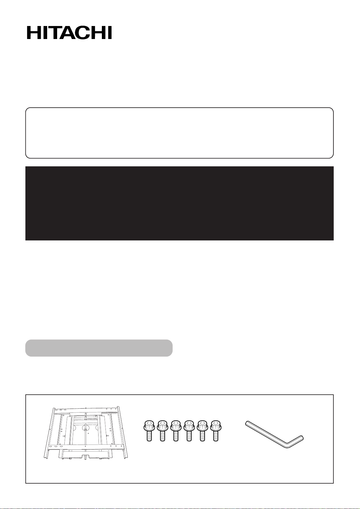
Parts Configuration Chart
Bolts M8 (6)
Hung on wall unit (1)
Hexagon wrench (1)
■Confirming the parts provided
Before assembly, check to make sure that none of the parts provided are missing.
* Screws to be used for wall installation are not included. Obtain them separately.
Page 2
−2−
Usage cautions to ensure correct usage
●The following symbols are used to ensure safe usage of the product, to prevent danger to yourself and other
parties and to prevent damage to property.
Symbols
■ This symbol indicates that incorrect handling due to ignoring this symbol
can result in the possibility of personal injury or even death.
■This symbol indicates additional
cautions (including warnings).
WARNING
Caution
(general)
■This symbol indicates forbidden
actions.
■This symbol indicates required actions.
Safety Cautions
Contact your
local dealer.
Disconnect the
power plug from
the power outlet.
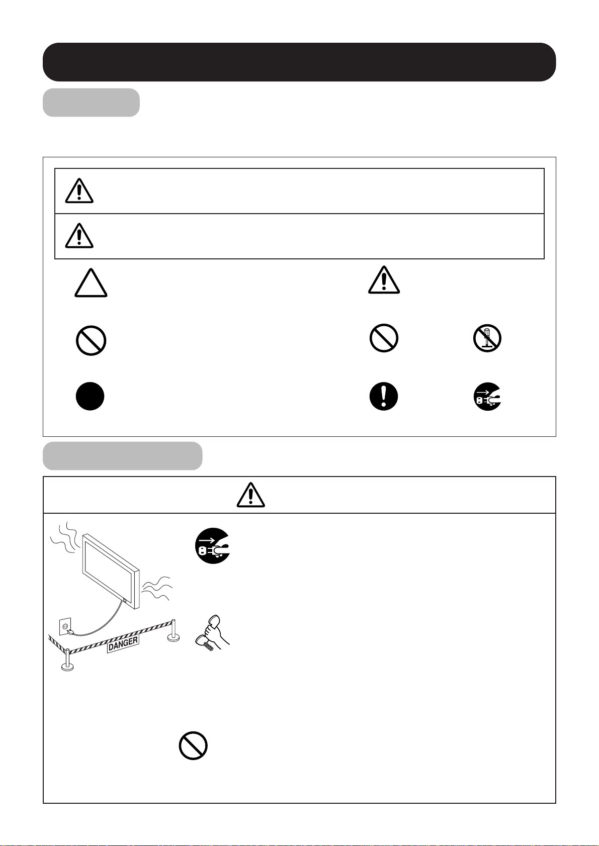
■When a malfunction occurs, disconnect the power
plug from the power outlet and take measures to
prevent other people coming near the plasma
display.
In the cases such as
●
The plasma display is loose and vibrates to an extreme degree,
●
Mounting screws or parts are loose or missing,
failure to take appropriate actions can result in injury.
Perform the following actions immediately whenever a
malfunction occurs.
①Turn off the plasma display power switch.
②Disconnect the power plug from the power outlet.
③Surround the area with rope, etc., to prevent other people
coming near.
④Contact your local dealer.
■Ask your dealer to install, move or adjust the wallmount unit.
Incorrect installation or adjustment can cause the plasma display
to fall.
Handling by other than
professional contractors
is prohibited.
■ This symbol indicates that incorrect handling due to ignoring this symbol
can result in the possibility of personal injury and physical damage.
CAUTION
Forbidden
(general)
Required
(general)
Disassembly
prohibited
Indicates that the power plug is to be
disconnected from the power outlet.
WARNING
Page 3
Pillar or
thick ply wood.
Plaster board or
thin ply wood, etc.
−3−
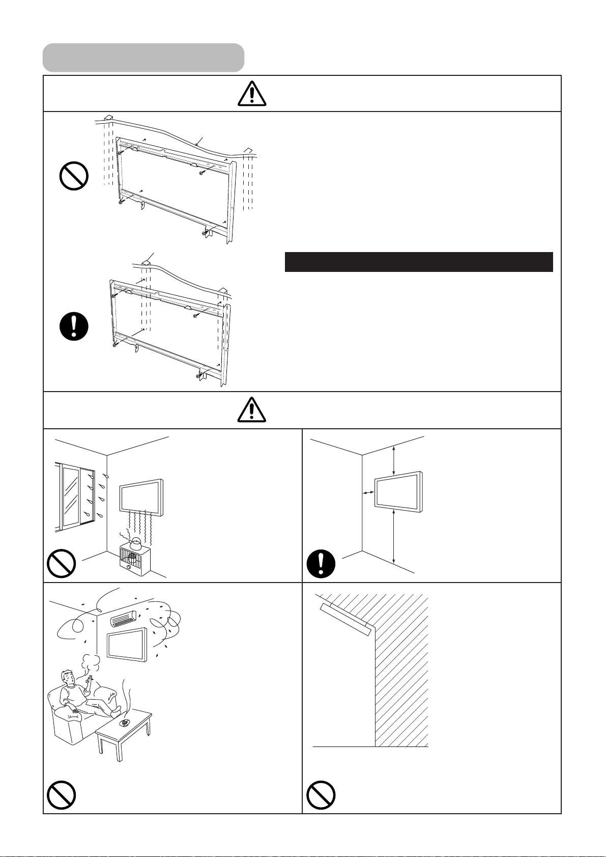
■The wall where the wall-mount unit is to be
installed must be capable of long-term
support of the total load of the plasma display
and wall-mount unit. Measures should also be
taken to ensure sufficient strength to
withstand the force of earthquakes, vibration
and other external for ces.
Incorrect installation can cause the plasma display to fall
and cause injury.
●
Installation on a wooden wall
Always install so that the load is supported by a piller. If the
strength of the piller is insufficient, add reinforcement. Do
not install on plasters or decorative posts.
●
Installation on a concrete wall
Use commercially available anchors that are capable of
fully supporting the load of the plasma display.
10cm
or more
10cm
or more
10cm
or more
■ Avoid installing in
locations where the
temperature and
humidity are
excessively high,
and where contact
with water is
possible.
These can result in fire
or electrical shock.
Installation Location
WARNING
CAUTION
■ Do not install close
to an airconditioner intake
or outlet.
Do not install in
locations where
there is excessive
amounts of dust,
oily smoke or
tobacco smoke.
Fire could result.
■ Do not block the
ventilation holes.
Also provide
sufficient clearance
in regard to the
surroundings to
avoid blocking the
ventilation.
The internal
temperature could
elevate and possibly
result in fire.
■ Mount only on a
vertical, rigid wall
surface.
The internal
temperature could
elevate and possibly
result in fire.
Injury or damage could
also result from falling.
Model 50 Total load of the (plasma display + wall-mount unit) = 52.7kg
Page 4
−4−
Installing
CAUTION
■ Do not install in
locations where
there is excessive
vibration or impact.
Injury and damage
could result from
falling.
WARNING
■ Do not install where
there is direct
sunlight and other
strong light.
Strong light could result
in eye fatigue during
usage.
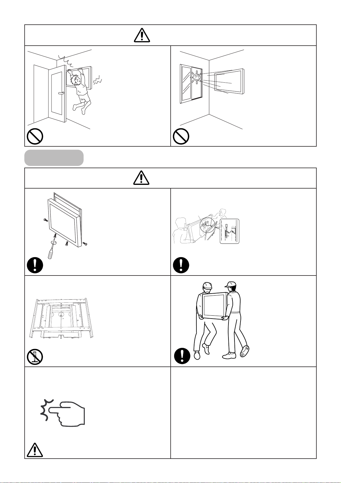
■ Use the specified
bolts and screws in
the specified places
and tighten firmly.
Failure to do this could
cause injury if the
plasma display falls.
■ Make sure the
display fittings and
wall-mount fittings
are firmly engaged.
Failure to do so could
cause the plasma
display to fall.
■ Do not alter any of
the parts. And do
not use broken
parts.
This could result in
injury due to the
plasma display falling.
■ Always use at least
two people to
perform the
installation work.
Injury could result from
dropping heavy
objects.
■ Use care to prevent
the fingers being
caught.
Hook
Page 5
−5−
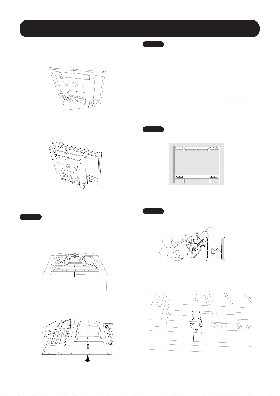
Installation Method
■ Installation procedure
1
Remove the special screws (2 locations) from the
bottom of the hung on wall unit.
Special screws (M6)
2Remove the hardware on the wall side and the
hardware on the PDP side.
Wall side hardware
PDP side hardware
Plasma display
PDP side hardware
Top side of plasma display
3
Attach the PDP side hardware to the plasma
display.
Warning
• Cover the display with a sheet or similar protective material
to protect it from scratches or other damage.
• Be sure to attach it on top of a flat table or similar surface.
4 Fix the plasma display to the PDP side hardware
with bolt M8 (6 locations). Usually, use the holes
marked with the red triangle "∆".
Top side of plasma display
7 Fix the bottom of the hardware with the special
screws removed at step 1 (one on the left and
one on the right).
Special screw (M6)
5 Attach the wall side hardware to the wall.
Install the wall side hardware (4 locations)
symmetrically on the left and right side (one at
each location from the center of the ).
Because the screws and bolts used to do this
are different according to the wall strength and
wall material, purchase suitable screws and
bolts separately.
Warning
Check the strength of the wall and beams before installing the
display.
Warning
Be sure to install the speaker at this stage.
・For the installation method, refer to the speaker installation
procedure in the speaker user manual.
6
Attach the hook on the PDP side hardware to the
wall side hardware.
Warning
Do not hold the speakers during the installation work.
Page 6
−6−
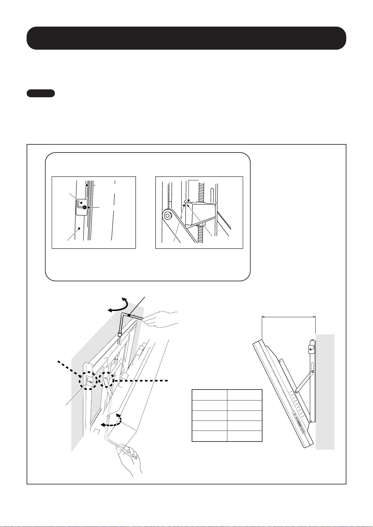
Installation Method
(A) Criterion for the vertical
location
(B) Criterion when its angle is
25ˇ
When it is in this state, do not
turn the adjustment screw any
further in the closing direction.
When it is in this state, do not turn
the adjustment screw any further
in the opening direction.
Hexagon wrench
Opening
Closing
Resin plate
Measuring the opening distance X
enables approximate angle values to
be determined.
X
Tilt Angle Criteria
Angle X
5°
133mm
10°
188mm
15°
241mm
20°
291mm
■ Angle setup
This installation hardware allows the display to be directed downwards freely at any angle from the vertical to 25ˇ.
This adjustment must always be done by 2 people.
Adjust the angle by rotating the screws at the center top and center bottom of the wall side hardware to the left or right.
Warning
・ If the angle is increased while you are adjusting the angle using the screw at the center of the bottom, it is difficult to turn the
screw. When this happens, adjust it at the center of the upper.
・Turn the screws very carefully to avoid damaging the wall.
・When a screw becomes tight at either end of the adjustment range, do not turn the adjustment screw any further, because if
you do, you will apply excessive force, deforming the screw.
Gap
disappears
Wall side hardware
Back of the
plasma display
Resin plate
End face of the plate
Notch
Matched in both
directions
A
B
Page 7
−7−
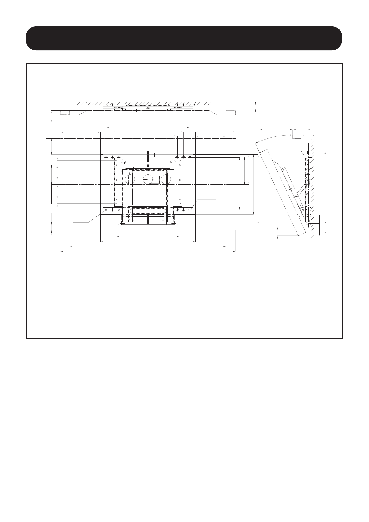
Product Specifications
External Dimensions
Mass 13.8kg
Main material Steel sheet
Surface treatment
Black baked paint
Products mounted
CMP5000WX
59
6-φ10.5
6-23x10.5
(314)
(239)
(314)
239
33
35
150 150
35 35
714
(44)
455
555
655
496
740
1368 (With side speaker)
545
465
232
212
410
(143)
45
44 573
(258)
54
(43)
1218 (Without side speaker)
98
(125)
25°
Page 8

Hitachi, Ltd. Tokyo Japan
Digital Media Division
292 Yohida-cho, Totsuka-ku, Yokohama,
244-0817 Japan
(045) 866-6302
 Loading...