

Page 1
ENGLISH
FEATURES
Notes about This Manual
•
The information in this manual is subject to change without notice.
•
While meticulous care has been taken in the preparation of this manual, you are
requested to notify your dealer or us should you have any comments, views or
questions about our product.
•
Fully understand the prerequisites to using the product, such as hardware and
software specifications and constraints, in using the product. We are not held liable
for damages caused by improper handling of the product.
•
Reproduction of this manual in whole or in part without our prior written permission
is prohibited.
•
The product names mentioned in this manual may be trademarks or registered
trademarks of their respective owners.
The following features are provided by the color Plasma Display Monitor.
Large-screen, high-definition plasma display panel
The 37-inch color plasma display panel, with a resolution of 1024 (H) x 768(V) pixels,
creates a high-definition, large-screen (aspect ratio : 4:3) and low-profile flat display.
Free from electromagnetic interferences from geomagnetic sources and ambient power
lines, the panel produces high-quality display images free from color misconvergence and
display distortion.
Multimedia input support
The monitor comes complete with a mini-D-sub terminal and a BNC terminal for RGB
input and with a composite/S terminal and a component terminal for video input, and
even with stereo audio input terminals. It allows hooking up with a number of devices,
from PCs to video gear.
Multiscan converter and progressive LSI
The multiscan converter provides a broad multiscan range of signals (*1), from video
signals (15 kHz) to PC analog video signals. Video input is subjected to progressive
processing by a dedicated LSI to offer better video quality.
(*1) Video performance of input signals in excess of 1024 x 768 (fields) is not
guaranteed, as they appear in a simplified display mode.
Easy-to-use remote controller and EasyMenu
The remote controller included eases the work of setting display controls. Further, the
on-screen display system, EasyMenu, displays the status of signal reception and display
control settings in an easy-to-view fashion.
Power saving system
International energy star and a power saving system are provided. The power-saving
system operates automatically to reduce power consumption even when there is no video
input signal.
1
Page 2

FEATURES 1
CONTENTS 2
SAFETY GUIDELINES 3
INSTALLATION INSTRUCTIONS 7
Standard accessories 7
Installation 7
Anti-tumble measures 7
Component Names 8
Installation and Cabling 10
Handling the Remote Controller 12
OPERATING INSTRUCTIONS 13
Turning Power On and Off 13
Input Selection 14
Volume Adjustment 14
Contrast Adjustment 15
Sound Mute 15
Input Signal Status Display 15
On-Screen Display System, EasyMenu 16
OTHER FEATURES 22
Automatic Store 22
Reset (Settings Initialization) 23
Signal Check 23
Switching the Display Method 24
Power Save Mode 25
Sound Mode 25
TROUBLESHOOTING 26
Symptoms That Seemingly Appear to be Failures
26
Actions to Correct Abnormal Displays 27
PRODUCT SPECIFICATIONS 28
General Specifications 28
Signal Input 29
Factory Settings 30
ENGLISH
CONTENTS
2
Page 3
ENGLISH
SAFETY GUIDELINES
This monitor is designed to be safe to use. However, due to high voltage of about 400 V,
fire or serious injury may occur unless you use this monitor in correct way.
You are strongly suggested to follow the instruction shown below in order to avoid such
injury.
Keep the safety guideline
Do not use the monitor if it fails
If you find something unusual ,
♦ If smoke comes out,
♦ If there is a strange smell,
♦ If water enters the case,
♦ If you drop the monitor or
damage the cabinet,
(1) Turn off the monitor
(2) Disconnect the power plug
from the power point
(3) Request for repair
Warning and Caution are indicated in this guide and monitor itself.
Fire or electric shock may cause death or serious injury unless you
follow the instruction.
Warning
Electric shock or other accidents may cause serious injury or damage
of your properties.
Caution
3
Page 4
ENGLISH
Fire or electric shock may cause death or serious injury unless you
follow the instruction.
Warning
● If something smells strange or smoke comes from the monitor:
Turn off the monitor and disconnect the power plug from the power point immediately.
Contact service center after confirming that the smoking has stopped.
If you continue to operate the monitor with such abnormal condition, it may cause fire or you may
receive an electric shock.
● Do not drop water or a foreign substance on to the monitor.
If you drop water or a foreign substance on to the monitor, it may cause fire or an electric shock.
If it happens turn off the monitor and disconnect the power plug from the power point and ask service
center for instruction.
● Do not put the monitor on an unstable place.
If you put the monitor on an uneven or unstable place, it may fall down and you may be injured.
Put the monitor on a flat surface strong enough to take the weight.
● Do not apply shock to the monitor.
If no picture, glass broken, smoke or something is smelling after applying shock to the monitor, turn off the
monitor and disconnect the power plug from the power point immediately. Then, call the service center.
If you continue to operate the monitor with such abnormal conditions, it may cause fire or you may
receive an electric shock.
● Do not disassemble or modify the monitor.
There is high voltage portion inside of the monitor. Disassembling or modification of the monitor may
cause fire or electric shock.
● Do not use the monitor in wet environment.
If you use the monitor in a wet place such as bath or shower room, it may cause fire or electric shock.
Using the monitor beside a window when snowing or raining or by a seaside are not recommended.
● Do not damage or modify the power cord.
If you put something heavy on the power cord or pull, squeeze, heat the cord, it may be damaged and
it may cause fire or electric shock. If the power cord is damaged, call service center.
Fire or electric shock may cause death or serious injury unless you
follow the instruction below.
Warning
SAFETY GUIDELINES(continued)
4
● The enclosed power cord must be used!
Failure to do so may cause electric shock hazard or fire hazard.
In USA/Canada, use a UL LISTED/CSA LABELLED or CERTIFIED power cord set meeting the
following specifications :
Rating: min. 125V, 10A , Length: max. 3.0m , Type: SVT or SJT
Plug type: NEMA 5-15P figure, Parallel blade, Grounding type
● Use only the correct voltage power outlet with safety ground connection!
100 - 120 V for USA, Canada, etc. 200 - 240 V for Europe, etc.
(This monitor will automatically adjust to the input voltage 100 - 120 / 200 - 240V.)
● Be careful of power cord connection!
Before inserting the plug of the power cord into a socket of the correct voltage, check that the
connection portion of the power cord is clean (with no dust). Then, insert the plug of power cord into
the socket firmly, otherwise it may cause electric shock or fire hazard.
● Do not touch the power plug when lightning is close to you.
You may receive an electric shock.
● Do not touch the power plug with wet hands.
You may receive an electric shock.
● Do not obstruct a ventilation hole.
If you obstruct a ventilation hole during the operation of the monitor or just after switching off the
power, it may cause a fire or electric shock due to heating up the monitor.
• Do not put the monitor screen side up.
• Do not put the monitor on a shelf or in a cabinet.
• Do not put the monitor on a carpet or mattress.
• Do not cover the monitor with a cloth.
Page 5
ENGLISH
Electric shock or other accidents may cause serious injury or damage to
your property.
Caution
● You must to check the user manual of the computer when you connect to
the monitor.
The weight of the monitor or obstructing the ventilation hole of the computer equipment may cause
distortion or damage of the computer equipment.
● Disconnect the power plug from the power point when you carry the monitor.
Carrying the monitor without disconnecting the power plug from the power point may damage the
cord and cause a fire or electric shock. You are advised to carry the monitor with two persons.
Handle with care when you carry the monitor, particularly take care of glass screen.
● When you disconnect the power plug.
You have to grasp the power plug itself, do not pull the power cord.
If you pull the power cord, you may damage it and it may cause a fire or electric shock.
Do not touch the power plug just after disconnecting it from the power point or you may receive an
electric shock.
● Disconnect the power plug from the power point when you don't use the monitor
for a long time.
This is just for your safety.
● Do not put the monitor in atmosphere with soot, steam, high humidity, and dust.
It may cause a fire or electric shock.
● Do not put the monitor in high temperature atmosphere.
Do not put the monitor in the place exposed to the direct rays of the sun or inside car under the burning
sun for a long period of time. Heat may cause a fire, transformation, or melting of the monitor.
● Do not put things on the monitor.
Do not put things on the monitor or give some shock to the monitor.
The monitor may fall down or drop from a desk. And it may cause injury.
5
You may have serious injury or your property may be damaged unless
you follow the instruction below.
Caution
● Do not bundle the power cord.
It will be heated up or it may cause a fire.
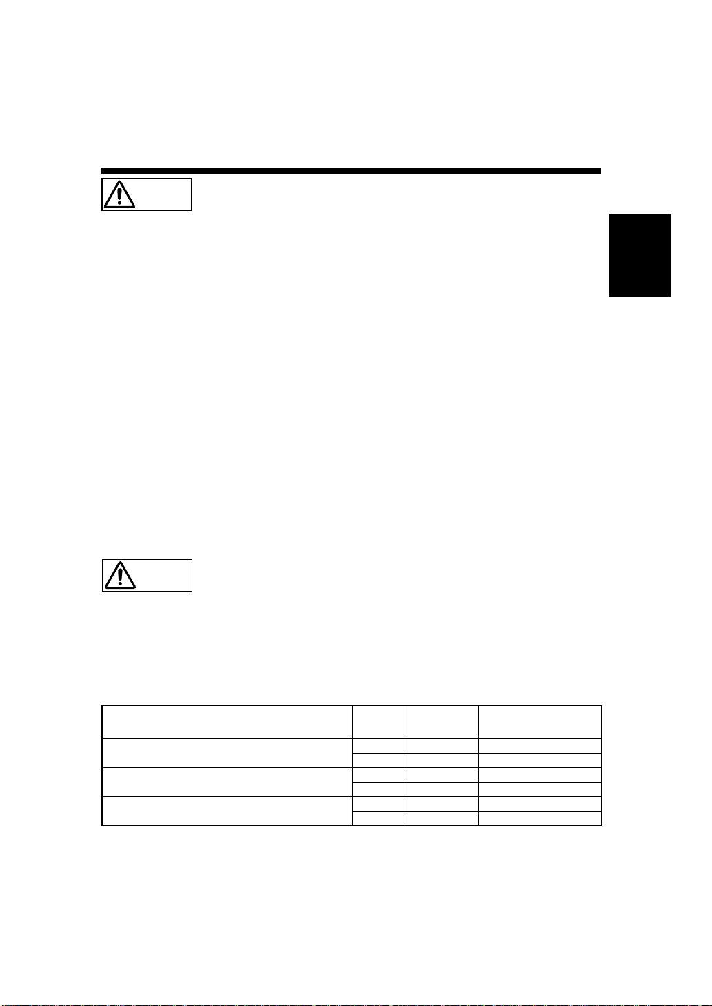
■ Caution for 200 - 240V operation only
This equipment relies on the protective devices in the building installation for short - circuit and over current protection. Refer to the following table for the suitable number and location of the protective
devices which should be provided in the building installation.
INFORMATIVE EXAMPLES OF PROTECTIVE DEVICES IN SINGLE - PHASE
EQUIPMENT OR SUB - ASSEMBLIES
Verify that the protective devices in the building installation meets the conditions in the table prior to installing the equipment.
■ Remove the power cord for complete isolation!
For complete isolation from the power source, remove the power cord from the monitor or from the
wall socket.
Protection
against
Minimum number
of fuses or circuit -
breaker poles
Location
Case A: Equipment to be connected to POWER SYSTEMS
with earthed neutral reliably identified, except for
Case C below.
Earth faults 1 Phase conductor
Overcurrent 1 Either of the two conductors
Case B: Equipment to be connected to any supply, including IT
POWER SYSTEMS and supplies with reversible plugs,
except for Case C below.
Earth faults 2 Both conductors
Overcurrent 1 Either of the two conductors
Case C: Equipment to be connected to 3 - wire power
systems with earthed neutral reliably identified.
Earth faults 2 Each phase conductor
Overcurrent 2 Each phase conductor
Page 6
6
ENGLISH
Precautions
SAFETY GUIDELINES(continued)
● Installation environment
Do not obstruct a ventilation hole.
Do not put the monitor on carpet or blanket, or near a curtain which has a possibility of obstructing a ventilation hole of the monitor.
Do not put the monitor in the following places.
◆ Hot places such as near heater, place exposed to the direct rays of the sun.
◆ A place where the temperature is widely changing.
◆ Places with soot, dust or high humidity.
◆ Poor air ventilation place.
◆ Place near fire.
◆ A wet place such as bathroom, or shower room.
◆ Place where you can trip over it.
◆ Always vibrating or strongly vibrating places.
◆ Distorted or unstable places.
● How to view the monitor.
If you use the monitor in too dark a room, your eyes may become tired. Please use it in a reasonably bright room.
Avoid direct rays of the sun or room falling on to the screen in order to prevent eye fatigue.
To use the monitor for a long time may cause damage to your eyes such as “Dry eye” or “Short-sightedness”
Please take a rest of 10-15 min. for every one hour viwed. Please watch the monitor in downward direction.
● How to clean the monitor.
Before cleaning the monitor, turn off the monitor and disconnect the power plug from the power point.
When cleaning the monitor, do not spray directly the screen or cabinet with cleaner.
Use a clean, dust free, dry and soft cloth. If it is not enough, then use a cloth with non-alcoholic or non-ammoniac detergent.
Do not rub the surface of the screen with ball-point-pen or screw-driver etc.
● Prevention of an obstacle to TV/Radio receivers
This monitor has been designed pursuant to the FCC Rules and so on in order to prevent a problem to TV/Radio receivers.
However, this monitor may cause a problem to TV/Radio receivers if you put this monitor close to them.
● Precautions for the monitor
-
Use the attached signal-cable when you connect the monitor with PC equipment. Do not use other signal-cables.
- Confirm the connector is fixed tightly when the signal cable is connected.
Also confirm the screws on the connector are tightened.
-
Plug the power cord of the monitor into a different socket from that for other equipment, such as TV, Radio etc..
- Use a plug with ground terminal and make sure that it connects to the ground.
● Precautions for TV & Radio
- Keep the monitor away from TV or Radio.
- Adjust TV or radio antennas in order for the monitor not to receive interference.
- The antenna cable of TV or Radio should be kept away from the monitor.
- Use a coaxial cable for antenna.
You can check if this monitor influences TV/Radio receivers by turning off all other equipment other than the monitor.
If you can find a problem receiving TV/Radio when using the monitor, check the instructions mentioned above.
● Precaution during transportation
Please pay attention when you transport this monitor because it is heavy.
Furthermore, use the specific carton box and its packaging materials when the monitor is transported.
■ FCC (Federal Communications Commission) Statement Warning
W
ARNING:
This equipment has been tested and found to comply with the limits for a Class A digital device,
pursuant to Part 15 of the FCC Rules. These limits are designed to provide reasonable protection against harmful
interference when the equipment is operated in a commercial environment. This equipment generates, uses, and can
radiate radio frequency energy and, if not installed and used in accordance with the instruction manual, may cause
harmful interference to radio communications. Operation of this equipment in a residential area is likely to cause
harmful interference in which case the user will be required to correct the interference at his own expense.
INSTRUCTIONS TO USERS: This equipment complies with the requirements of FCC (Federal
Communication Commission) equipment's provided that follwing conditions are met.
CAUTION: Changes or modifications not expressly approved by the party responsible for compliance could void
the user's authority to operate the equipment.
(1) Power cord : The grounded power supply cord must be used.
(2) Signal cable : The provided signal cable must be used.
Page 7
7
ENGLISH
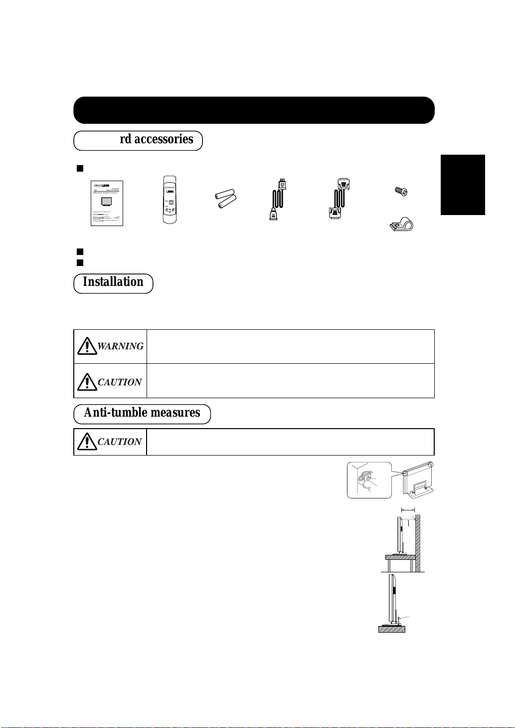
● To preserve the performance of this product and to maintain safety, always use one of the special mount
units for installation.
Special mount units (options): Wall Mount Unit (CMPAK04), Ceiling Mount Unit (CMPAT04)
■ Use one of the special mount units to install this product. A mount of insufficient strength or
inadequate design can cause overturning or dropping and result in fire, electrical shock or injury.
Please note that this company assumes absolutely no responsibility for personal injuries or
property damage caused by use of other mount units or improper installation.
■ Installation of the wall mount unit and ceiling mount unit can be dangerous, so do not attempt
this work yourself. Ask your dealer to provide the name of a qualified installer.
■ In order to prevent an internal temperature increase, maintain a space of 10cm or more between
the sides and other objects such as walls, etc., so that the ventilation holes are not blocked.*
INSTALLATION INSTRUCTIONS
1) Using M4 screws (two), fasten the hooks included to the screw
holes at both ends of the top of the rear of the set as shown.
2) Using a commercially available cord, chain and clamp, secure the
set to a firm wall or post.
● This product is complete with the display monitor, plus the accessories shown below.
If any of these accessories is missing, please contact your dealer.
Read the instruction manual (this book) and the warranty card carefully and keep them in a safe place for handy reference.
Retain the packing materials for use in future shipping or relocation.
Instruction manual
(this book)
Power cable
Signal cable, mini-
D-sub 15-pin
Remote-control
transmitter
Size AA
batteries x 2
Securing to a wall or post
Securing desktop
1) Using wood screws (two), fasten the set to the clamping screw
holes on the rear of the stand as shown.
2) Using commercially available wood screws, secure the set firmly
in position.
M4 screw x 2
Hook x 2
Screw
Hook
Cord or Chain
Cord
or
chain
Clamp
10cm or more*
Two places
Wood screw
■ Have this unit mounted in a stable place. Take measures to prevent it from tumbling down to
avoid possible physical injury.
READ THE INSTRUCTIONS INSIDE CAREFULLY.
KEEP THIS USER MANUAL FOR FUTURE REFERENCE.
Forfuturereference,recordthe serialnumberofyour monitor.
SERIAL NO.
Theserialnumberis locatedontherearof themonitor.
Thismonitoris
ENERGYSTAR®
compliantwhenusedwith a
computerequippedwithVESA DPMS.
The
E
NERGYSTAR®
emblemdoesnotrepresent EPAendorsement
ofanyproductor service.
Asan
E
NERGYSTAR®
Partner,Hitachi,Ltd.hasdetermined thatthisproductmeetsthe
ENERGY
STAR®
guidelinesforenergyefficiency.
with
EasyMenu!
EasyMenuisHITACHI'sOn ScreenDisplayfunctionforeasy operation.
USER MANUAL
MANUEL UTILISATEUR
Color Plasma Display Monitor
CMP307EU
Standard accessories
Installation
Anti-tumble measures
Page 8
8
ENGLISH
INSTALLATION INSTRUCTIONS (continued)
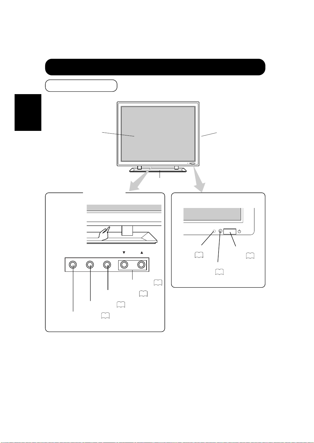
Remote-control
sensor
Front
Cabinet
(front frame)
Stand
12
Panel
Indicating
lamp
13
Control panel
RGB/VIDEO
[VOLUME]
SELECTMENU
VOLUME button
14
MENU button
16
RGB/VIDEO button
14
SELECT button
16
■ The Adjustment
button is located
on the bottom.
Subpower
button
13
Component Names
STANDBY(RED)
ON (GRN)
Page 9
9
ENGLISH
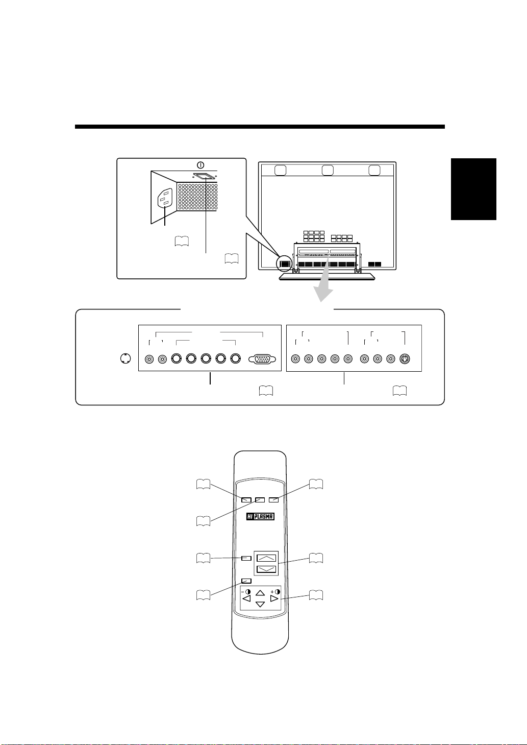
Remote controller
POWER RECALL
RGB/
VIDEO
MUTE
VOLUME
MENU
SELECT
RGB/VIDEO button
14
POWER button
13
RECALL button
15
MUTE button
15
MENU button
16
VOLUME button
14
SELECT button
15
External device connection terminals
Rear
RGB input terminals
10
S-VIDEO
VIDEO1INPUT
VIDEO
VIDEO2INPUT[COMPONENT]
PR/CRPB/CBYRL
(MONO)
AUDIO
RL
(MONO)
AUDIO
RGBINPUT
RS232CIN
RL
(MONO)
VHBGR
AUDIO
[D-SUB]
[BNC]RGB2
RGB1
Main power switch
Power cable
connector
10
13
VIDEO input terminals
11
Page 10

10
ENGLISH
INSTALLATION INSTRUCTIONS (continued)
Connecting to the PC
Read Usage Notes ( to ) carefully to ensure maximum safety before proceeding to
these steps:
(1) Make sure that the display signals produced by your PC meet the specifications of this
product.
For the specifications of this product, see Product Specifications ( to ).
(2) Choose an appropriate site and install the product on a level table where the stand is secure.
Install the monitor to have ready access to a power socket.
(3) Make sure that the monitor’s power switch is off.
The monitor is shipped with the power switch off.
(4) Make sure that your PC’s power switch is off.
(5) Interconnect the signal input terminal (RGB1) on the monitor rear panel and the display
signal output terminal of the PC to each other using the signal cable included.
Optional cables are needed to connect to the RGB2 input and audio input terminals.
If the signal cable included does not match your PC, consult your dealer after reading the section
“Signal Input”.
(6) Insert one end of the power cable included into the rear-panel power cable connector and
the other end into a power socket.
If a power adapter is used, ground the grounding wire to avoid electrical shocks and radio
interference. (Complete grounding before connecting the power plug to a power supply. Before
disconnecting the grounding wire, be sure to disconnect the power plug from the power supply
first.)
(7) Turn on the monitor, then the PC to make sure that a display image appears on the monitor
screen.
For instructions on turning on the monitor and adjusting its display images, see “Operating
Instructions” ( to ).
28 30
13
21
Installation and Cabling
3 6
Monitor rear panel
To audio input
terminals
Power cable
Power cable
connector
AUDIO
(MONO)
VHBGR
RL
RGB INPUT
[ BNC ]RGB2
To signal input
terminals
RGB1
[ D-SUB ]
To signal input
terminals
PC
To signal output
terminal
To signal output
terminal
To audio output
terminal
Page 11

11
ENGLISH
Connecting to Video Equipment
(such as a video disc player, a DVD player, or a video camera)
S-VIDEO
VIDEO1 INPUT
VIDEO
VIDEO2 INPUT [COMPONENT]
PR/CRPB/CBYRL
(MONO)
AUDIO
RL
(MONO)
AUDIO
Power cable
connector
Video equipment
(such as a video disc player,
a DVD player, and a video camer)
To audio output
terminals
Red(R)
White(W)
Red(R)
White(W)
Red(R)
White(W)
To component
output terminals
Use if the video
equipment has an
S video input terminal
To audio/video
output terminals
To audio/video
intput terminals
Red(R)
White(W)
Yellow(V)
Yellow(V)
To S video
output
terminals
To S video input
terminals
To audio input
terminals
To component
input terminals
Monitor rear panel
Power cable
Read Usage Notes ( to ) carefully to ensure maximum safety before proceeding to
these steps:
(1) Choose an appropriate site and install the product on a level table where the stand is secure.
Install the monitor to have ready access to a power socket available.
(2) Make sure that the monitor’s power switch is off.
The monitor is shipped with the power switch off.
(3) Make sure that the video equipment’s power switch is off.
(4) Interconnect the signal input terminal on the monitor rear panel and the video equipment’s
signal output terminal to each other using an optional cable.
(5) Insert one end of the power cable included into the rear-panel power cable connector and
the other end into a power socket.
If a power adapter is used, ground the grounding wire to avoid electrical shocks and radio
interference. (Complete grounding before connecting the power plug to a power supply. Before
disconnecting the grounding wire, be sure to disconnect the power plug from the power supply
first.)
(6) Turn on the monitor, then the video equipment’s to make sure that a display image appears
on the monitor screen.
For instructions on turning on the monitor and adjusting its display images, see “Operating
Instructions” ( to ).
If video equipment with an S video input terminal is used, cabling by the S video cable is
recommended to provide finer video quality. (If an S video input terminal and a video
input terminal connect to the monitor at the same time, S video input would govern.)
13 21
3 6
Page 12

12
ENGLISH
INSTALLATION INSTRUCTIONS (continued)
Loading Batteries
(1) Open the battery cover.
Slide the battery cover towards the arrow mark while pressing it.
(2) Load batteries.
Load two Size AA batteries included observing the correct polarities.
When replacing the batteries, always use the R6P AA (or SUM-3) type.
(3) Close the battery cover.
Slide back the battery cover towards the arrow mark.
CAUTIONS
Do not drop or impact the remote controller.
Do not splash the remote controller with water or put it on a wet object
to avoid possible failures.
Before leaving the remote controller out of use for an extended period
of time, remove the batteries from it.
If the remote controller begins to lack responsiveness, replace the
batteries.
Strong light such as direct sunlight impinging on the photoreceptor of
the remote control can cause operational failure. Position this unit to
avoid direct contact with such light.
Do not use batteries of any kind not recommended for this product. Do
not use new and old batteries together. The batteries could explode or
leak, resulting in fires, physical injury, or stains.
When loading batteries, observe their correct polarities as marked on
the product. If loaded in the wrong direction, the batteries could
explode or leak, resulting in fires, physical injury, or stains.
TIPS
Handling the Remote Controller
Use the remote controller within about 5 m from front of the unit’s
remote-control sensor and within 30 degrees on both sides.
SELECT
With in 30
degrees
With in 30
degrees
About 5m
Handling the Remote Controller
Page 13

13
ENGLISH
When the indicating lamp blinks in green or the message “POWER
SAVE” or “OUT OF FREQUENCY” appears on the screen, there is
something unusual about the status of reception. See “Symptoms
That Seemingly Appear to be Failures.”
OPERATING INSTRUCTIONS
To turn on the set power supply, set the MAIN POWER switch ( ) of the main unit to ON and
then press the SUB POWER button ( ) or the POWER button of the remote control.
To turn off the set power supply, press the SUB POWER button ( ) of the main unit or the
POWER button of the remote control, then set the MAIN POWER switch ( ) to OFF.
For normal operations, leave the main power switch ( ) set to ON and use the sub power button or
the Power button of the remote control to turn the power on and off.
The indicating lamp lights when the power is turned on.
TIPS
Avoid repeatedly turning the monitor on and off at short time intervals.
Failures might result from such operation.
Turn off the main power switch ( ) before leaving the monitor out of
use for an extended period of time.
If a power failure occurs while the set is running, it would be powered
on upon recovery from the failure. Turn off the unit main power switch
before leaving the set.
26
Indicating lamp Power status
Lit in red OFF
Lit or flickering in green ON
POWER
Main power
switch
Set unit
Remote
controller
Turning Power On and Off
Page 14

14
ENGLISH
OPERATING INSTRUCTIONS
(continued)
The adjustment status will be displayed as guidance
while you press these buttons.
While the guidance is on display, press or ▲ to
turn up the volume.
While the guidance is on display, press or ▼ to
turn down the volume.
You can also adjust the sound volume setting via the
on-screen display system, EasyMenu
The sound volume adjustment mode will exit when no
keys are entered for 5 seconds. (The adjustment
status guidance will disappear automatically.)
While the on-screen display system, EasyMenu ( ) is not on display, press the remote
controller VOLUME button or (or the unit VOLUME button
▲ or ▼ to adjust
the sound volume.
VOLUME : 30
VOLUME
Set unit
Remote
controller
[ VOLUME ]
Press the RGB/VIDEO button on the remote controller or the unit to switch the input in the
sequence of RGB1
➝ RGB2 ➝ VIDEO1 ➝ VIDEO2 ➝ RGB1.
RGB1 (D-sub input)
RGB2 (BNC input)
VIDEO1 (
composite or S input
)
VIDEO2 (
COMPONENT input
)
RGB/
VIDEO
Remote
controller
RGB/VIDEO
Set unit
The kinds of input for which SKIP has been
selected with the on-screen display system,
EasyMenu ( ), are skipped.
16
16
Sound volume setting
Adjustment status guidance
21
Input Selection
Volume Adjustment
Page 15

15
ENGLISH
Press the remote controller MUTE button once again and the mute will be canceled and the
guidance will change to VOLUME (blue), enabling the volume to be heard.
When MUTE is used, the guide display will continue for 5 sec. and then turn off.
The set itself does not have a MUTE button.
While the on-screen display system, EasyMenu , is not on display, press the remote
controller SELECT button or to adjust the contrast.
SELECT
Remote
controller
16
MUTE : 30
Sound volume setting
Press the remote controller MUTE button to mute the sound temporarily.
When you press the button, [MUTE] (pink) and the status
of volume setting will be displayed in a guidance image.
While the sound is muted, press the button to turn down the
volume.
While the sound is muted, press the button to cancel the mute.
You can also adjust the sound volume setting of the mute
via the on-screen display system, EasyMenu .
Input terminal name
Press the remote controller RECALL button to display the status of input signals on the screen.
Press the remote controller RECALL button once again to exit the screen display.
The contrast adjustment mode will exit when
no keys are entered for 5 seconds.
The set itself does not have a RECALL button.
Input horizontal
frequency
Input vertical
frequency
16
When you press these buttons, the status of contrast
adjustment and the input horizontal (H) and vertical
(V) frequencies of the input signal will be displayed
in a guidance image.
While the guidance is on display, press the key to
narrow the difference between darkness and
brightness.
While the guidance is on display, press the key to
widen the difference between darkness and
brightness.
You can also adjust the contrast setting via the onscreen display system, EasyMenu .
The contrast adjustment mode will exit when no
keys are entered for 5 seconds. (The adjustment
status guidance will disappear automatically.)
16
CONTRAST : 100
H :
* *. *
kHz, V :
* *. *
Hz
Contrast setting
Input horizontal
frequency
Input vertical
frequency
(The display will turn to pink.)
Adjustment status guidance
Contrast Adjustment
Sound Mute
Input Signal Status Display
Remote
controller
MUTE
Remote
controller
RECALL
RGB1 [D-SUB]
H : 46.5kHz, V : 60Hz
Page 16

16
ENGLISH
OPERATING INSTRUCTIONS
(continued)
Press the SELECT buttons (remote controller
and keys) to move the pink marker to
select an item.
Press the VOLUME button and the ▲ and ▼
keys of the main unit ( or key of the
remote control) to adjust or set the selected
item, or to switch the menu.
When a choice is followed by “:”, it indicates that the
choice can be adjusted or changed.
When a choice is followed by ▲, a menu can be opened
by pressing the remote-controller SELECT button or
the set VOLUME button ▲.
When [RETURN] is selected, press the remotecontroller button SELECT or the set VOLUME
button ▼to exit to the original menu
For information on adjusting and setting
choices, see to .
Pink
Pink when brightness
is selected
Guidance
Press the MENU button once again to exit the adjustment menu.
The adjustment menu will close automatically when no keys are entered for 10 seconds.
17
21
Press the MENU button to open an adjustment menu allowing you to complete various
adjustments and settings using the SELECT buttons (remote controller , , ,and
keys, or the set SELECT key).
Set unit
MENU
SELECT
[ VOLUME ]
Menu selection mark
HINTS
■ Burn-in (residual image) can occur if the same image is displayed for an
extended time. To reduce this possibility, change the display contents at suitable
intervals. To reduce this, it is recommended that you either change the display
contents at an appropriate interval or use the Burn In function .
■ If special images created on a PC or any other equipment (such as those
composed of a checker-flag pattern) are displayed across the screen, the hue may
be varied depending on the contrast or brightness setting.
18
On-Screen Display System, EasyMenu
Remote
controller
MENU
SELECT
MAIN MENU
PICTURE
SOUND
DISPLAY
FUNCTION
PICTURE MENU
CONTRAST :117
BRIGHTNESS : 0
COLOR SELECT:NORMAL
COLOR BALANCE
OPTIONS
RETURN
Page 17

17
ENGLISH
Adjustment Item List
Menu item
Selected
characters
Adjustment
item
Setup hint
M
A
I
N
PICTURE
(in RGB is
selected)
CONTRAST Contrast
Narrows the gap
between
brightness and
darkness.
Broadens the gap
between
brightness and
darkness.
Adjust for
maximum visibility
to suit the
ambient
brightness.
BRIGHTNESS Brightness
Black is subdued
for
increasedoverall
darkness.
Black is set off for
increased overall
brightness.
Adjust to prevent
black from
spreading across
the screen.
COLOR SELECT Color mode
COOL
↑
NORML
↑
WARM
↑
USER
COOL
↓
NORML
↓
WARM
↓
USER
Set to the desired
colors.
COLOR
BALANCE
R-GAIN Red gain Red is weakened.
Red is
strengthened.
Sets the color
adjustment
selected by the
user with COLOR
SELECT.
G-GAIN Green gain
Green is
weakened.
Green is
strengthened.
B-GAIN Blue gain
Blue is
weakened.
Blue is
strengthened.
OPTIONS
PRESENTATION Presentation
Sets to PUBLIC.
Sets to THEATER.
It can be selectd
in 60 Hz vertical
frequency or less.
Normally set to
PUBLIC. Set to
THEATER to
increase the
number of colors,
even when the
screen is dark.
GAMMA
Gamma
correction
1.0
↑
2.2
↑
2.8
1.0
↓
2.2
↓
2.8
Normally set to
2.2.
VIDEO LEVEL Input signal level Set to 0.7 V. Set to 1.0 V.
Normally set to 0.7
V. If white is found
to spread across
the screen, set to
1.0 V.
Page 18

18
ENGLISH
OPERATING INSTRUCTIONS
(continued)
Adjustment Item List (continued)
Menu item
Selected
characters
Adjustment
item
Setup hint
M
A
I
N
PICTURE
(in VIDEO
is selected)
CONTRAST Contrast
Narrows the gap
between
brightness and
darkness.
Broadens the gap
between
brightness and
darkness.
Adjust for maximum
visibility to suit the
ambient brightness.
BRIGHTNESS Brightness
Black is subdued
for increased
overall darkness.
Black is set off for
increased overall
brightness.
Adjust for visibility to
suit the darkness of
black hair.
COLOR
Color
(color density)
Lightens colors. Darkens colors.
Adjust for desired
density,somewhat for
lighter colors for a
natural look.
TINT Tint
Enhances red and
weakens green.
Enhances green
and weakens red.
Adjust for a nice
looking skin color.
SHARPNESS Sharpness
Softens display
images.
Sharpens display
images.
Normally set to
middle,and towardsfor increased
softness.
OPTIONS
COLOR SELECT Color mode
COOL
↑
NORMAL
↑
WARM
COOL
↓
NORMAL
↓
WARM
Set to the desired
colors.
PRESENTATION Presentation Sets to PUBLIC. Sets to THEATER.
Normally set to
PUBLIC. Set to
THEATER to
increase the number
of colors,even when
the screen is dark.
GAMMA
Gamma
correction
1.0
↑
2.2
↑
2.8
1.0
↓
2.2
↓
2.8
Normally set to 2.2.
VIDEO LEVEL
Input signal
level
NORMAL
↑
+10%
↑
+20%
NORMAL
↓
+10%
↓
+20%
Normally set to
NORMAL.If white is
found to spread
across the screen,set
to +10% or +20%.
SOUND
VOLUME Sound volume
Turns down the
volume.
Turns up the
volume.
Adjust for the desired
sound volume.
BALANCE Sound balance
Enhances left-side
sound.
Enhances rightside sound.
Adjust to taste.
TREBLE Treble
Suppresses
treble.
Enhances treble.
BASS Bass Suppresses bass. Enhances bass.
MUTE VOLUME Mute volume
Turns down the
sound
volume.Minimum 0.
Turns up the sound
volume.Maximum
pre-mute sound
volume.
Varies the sound
volume when the
MUTE button is
pressed.
15
14
Page 19

19
ENGLISH
Menu item
Selected
characters
Adjustment
item
Setup hint
M
A
I
N
DISPLAY
(in RGB is
selected)
DISPLAY AREA
Display
area
NORMAL
NORMAL ↔ FULL
Set the display as
desired. Images are
easier to adjust at the
NORMAL setting.
SXGA
signal
vertical
frequency
60Hz
during
reception
NORMAL
↑
UP/LF
↑
UP/RI
↑
DW/LF
↑
DW/RI
↑
CENTER
NORMAL
↓
UP/LF
↓
UP/RI
↓
DW/LF
↓
DW/RI
↓
CENTER
H.POSITION Horizontal position
Moves the horizontal
position to left.
Moves the horizontal
position to right.
Adjust the left-side
display position.
V.POSITION Vertical position
Moves down the
vertical position.
Moves up the vertical
position.
Adjust the vertical
display position.
CLOCK Dot clock frequency
Reduces the dot clock
frequency(shrinks the
right side).
Increases the dot clock
frequency(expands the
right side).
Adjust for maximum
character clarity.
PHASE Dot clock phase
Slows the dot clock
phase(shifts slightly to
left).
Advances the dot clock
phase(shifts slightly to
right).
Adjust for clear
character visibility.
DISPLAY
INIT.
INITIALIZE Display initialization
Set to Yes. The Display
menu adjustment
values will be cleared
and the Display menu
will return.
Set to No. The Display
menu will return.the
adjustment values will
not be cleared.
Clear the user signal
preset data.
DISPLAY
(in VIDEO
is selected)
DISPLAY SIZE Display size
NORMAL
↑
WIDE
↑
SQ.N
↑
SQ.W
NORMAL
↓
WIDE
↓
SQ.N
↓
SQ.W
Set SQ.N or SQ.W when
a squeezed signal is to
be input.
NORMAL or WIDE
should be used
normally.
H.POSITION
Horizontal position
with an aspect ratio of
4: 3 and WIDE setting.
Moves the horizontal
position to left.
Moves the horizontal
position to right.
Adjust when images
and text around the
edge of the screen are
difficult to see.
Operates when the
screen size is WIDE or
SQ.WIDE.
Horizontal position with
an aspect ratio of 16: 9
and WIDE setting.
Moves the horizontal
position to left.
Moves the horizontal
position to right.
V.POSITION
Vertical position with
an aspect ratio of 4: 3
and WIDE setting.
Moves down the
vertical position.
Moves up the vertical
position.
()
24
27
27
23
24
24
Page 20

20
ENGLISH
OPERATING INSTRUCTIONS
(continued)
Adjustment Item List (continued)
Menu item
Selected
characters
Adjustment
item
Setup hint
M
A
I
N
FUNCTION
LANGUAGE
Language
selection
ENGLISH (E)
↑
DEUTSCH (D)
↑
ESPAÑOL (N)
↑
ITALIANO (I)
↑
FRANÇAIS (F)
ENGLISH (E)
↓
DEUTSCH (D)
↓
ESPAÑOL (N)
↓
ITALIANO (I)
↓
FRANÇAIS (F)
The default is
ENGLISH.
AUTO FREQ.
Input status
automatic display
Set to OFF. Set to ON.
Set to OFF if you find
the frequency
display appearing
upon signal change
embarrassing.
HALFTONE Half tone
Set to OFF.
Half tone display is
not possible when
the Adjustment menu
screen is opened.
Set to ON.
Half tone display is
possible when the
Adjustment menu
screen is opened.
Set to OFF when the
border(Half tone) of
the Adjustment menu
is bothersome.
FUNCTION
(in RGB is
selected)
INTERPOLATION Enlargement Set to DOUBLE. Set to LINEAR.
Set to DOUBLE to
see characters or
images crisp or to
LINEAR to view them
smooth.
F
U
N
C
T
I
O
N
V
I
D
E
O
1
LINE INTP. Line correction Set to OFF. Set to ON.
Set to ON when
playing a 3D-video
disc. Set to OFF in
most cases.
3D COMB
Three-dimensional
Y/C separation
Set to OFF. Set to ON.
Set to OFF if video
images appear
unnatural. Set to ON
in most cases.
VIDEO SYSTEM Video system
AREA1
↑
AREA2
↑
NTSC
↑
PAL
↑
SECAM
↑
4-NTSC
↑
M-PAL
↑
N-PAL
AREA1
↓
AREA2
↓
NTSC
↓
PAL
↓
SECAM
↓
4-NTSC
↓
M-PAL
↓
N-PAL
Select the color
system that
corresponds to the
video input signal.
Note :
NTSC,PAL,SECAM
and NTSC 4.43 are
switched automatically
when AREA 1 is set.
NTSC,M-PAL and
N-PAL are switched
automatically when
AREA 2 is set.
V
I
D
E
O
2
COMPONENT SD1
480I
signal color matrix
Set to Cb/Cr to suit
the Y/CB/CR signals.
Set to Pb/Pr to suit
the Y/PB/PR signals.
Set to suit the color
matrix of the input
signal.
COMPONENT SD2
European SDTV
signal color matrix
COMPONENT HD1
480P
signal color matrix
COMPONENT HD2
720P
signal color matrix
COMPONENT HD3
1080I
signal color matrix
Page 21

21
ENGLISH
Menu item
Selected
characters
Adjustment
item
Setup hint
M
A
I
N
F
U
N
C
T
I
O
N
INPUT
SELECT
RGB1 INPUT
RGB1 input
selection
Sets to SKIP.
Do not select when
switching inputs.
Sets to SELECT.
Select when
switching inputs.
Setting an unused
jack to SKIP can
accelerate switching
speed.
In this case, the
selected jack will not
be displayed on the
screen.
RGB2 INPUT
RGB2 input
selection
VIDEO1 INPUT
VIDEO1 input
selection
VIDEO2 INPUT
VIDEO2 input
selection
RGB1 SOUND RGB1 audio
Sets to OFF.
There is no audio
output.
Sets to ON.
There is audio
output.
Determination of the
RGB audio signal
input jack.
RGB2 SOUND RGB2 audio
BURN
REDUCTION
SCREEN SAVER
Burn-in reduction
function
Sets to OFF. Sets to ON.
The image will move
automatically to
reduce burn-in. The
amount of movement
is set with “Moving
Dots” and the move
time is set with
“Moving Timer” (1 60 min.). (Use zero
(0) to check the
movement range.
The movement time
would be
approximately 1 sec.)
MOVING DOTS
Amount of screen
movement selection.
Reduces the amount
of movement.
Increases the amount
of movement.
MOVING TIMER
Movement time
interval selection.
Reduces the time
interval.
Increases the time
interval.
INVERSE Color inversion
Sets to OFF.
There is no color
inversion.
Sets to ON.
There is color
inversion.
Panel burn-in is
reduced after
extended display of
still images by
displaying the same
images again with
the colors inverted.
WHITE White
Sets to YES.
The Pattern menu
returns.(The display
is not all white.)
Sets to NO.
The display is all
white and the Pattern
menu returns.
Reduces panel
residual images when
executed after
displaying still images.
Page 22

22
ENGLISH
OTHER FEATURES
Approximately 1 sec. after adjustment is completed, the adjustments will be recorded as shown
in the table below.
The previously recorded items will be lost.
The signal mode can be identified by the horizontal/vertical sync frequency and the sync signal
polarity. Different signals with which all the elements are the same or similar will be handled as the
same signal.
RGB1 and RGB2 inputs have common elements that can be recorded for each signal mode. Because
of this, when the contents are recorded with RGB1 (or RGB2), there may be loss of adjustment
during RGB2 (or RGB1) reception in the same signal mode.
Item Registration condition
Reproduction condition
Sound volume
Sound balance
Treble
Bass
Mute volume
Input status automatic display
Half tone
Enlargement
Line correction
Three-dimensional Y/C separation
HD signal
Input select
One set can be recorded.
During normal signal
reception.
Brightness
Contrast
Gamma correction
Input signal level
Display area
One set can be recorded
during common RGB1, RGB2
input; one set of two can be
recorded during normal signal
reception with common
VIDEO 1, VIDEO 2 input.
During normal signal
reception.
Horizonal position
Vertical position
Dot clock frequency
Dot clock phase
One group can be recorded
for each signal mode.
During recording and
when the same signal
mode is detected.
Display
VOLUME
BALANCE
TREBLE
BASS
MUTE VOLUME
EASY MENU
HALF TONE
INTERPOLATION
LINE CALE
3D Y/C
COMPONENT
INPUT SELECT
BRIGHTINES
CONTRAST
GAMMA
VIDEO LEVEL
DISPLAY AREA
H.POSITION
V.POSITION
CLOCK
PHASE
Automatic Store
Page 23

23
ENGLISH
The status of signal reception is checked automatically and the result is displayed on the
screen.
Status Display Example
Signals are received
normally.
•The input terminal and the
horizontal and vertical frequencies
are displayed in a guidance image.
A sync signal could not be
detected.
❋Also includes the status
of the VESA-DPMS sync
signal.
•The guidance message “POWER
SAVE” is displayed for about 5
seconds.
•In the event of continued absence of
a sync signal, the power indicating
lamp flickers and the monitor enters
power save mode.
The input signal does not
meet display specifications
or erratic.
•Displays OUT OF FREQUENCY.
and the Guide. (After 5 sec. have
elapsed, the display darkens and
display continues until the correct
signal is received.)
Eithe VIDEO1 or VIDEO2 is displayed
on VIDEO input.
The Easy Menu shown to the right will be displayed when the
SELECT button is used to select DISPLAY and moreover
DISPLAY INT is selected from the On-screen Display
System Easy Menu during RGB1/RGB2 input. If the
key (select Yes) of the SELECT button is pressed at this time, the user adjustment values in the
table below for the signal currently being received will be deleted and the factory settings will
be restored.
Pressing the key (select No) cancels deletion and returns the DISPLAY menu.
Horizontal position
H.POSITION
Vertical position
V.POSITION
Dot clock frequency
CLOCK
16
Dot clock phase
PHASE
DISPLAY menu item
RGB1 [D-SUB]
H : 46.5kHz, V : 60Hz
POWER SAVE
OUT OF FREQUENCY.
28
30
Reset (Settings Initialization)
Signal Check
INITIALIZE?
YES NO
Page 24

24
ENGLISH
OTHERFEATURES
(continued)
1) The video signal when a screen with an aspect ratio (the ratio between the sides and width
of the screen) of 16: 9 is compressed to 4: 3.
* indicates signals and indicates screens in the chart above
●The display method can be switched by changing the settings of the display area (when the RGB input
jack is selected) or display size (when the Video input jack is selected).
Input signal ( )
(Resolution)
Display area setting (DISPLAY AREA)
NORMAL (normal number of pixels) FULL (expanded number of pixels)
640 x 400 640 x 400
1024 x 768
1)
640 x 480 640 x 480
800 x 600 800 x 600
832 x 624 832 x 624
1024 x 768 1024 x 768
1280 x 1024 1024 x 768
2)
(Squeezed display, partial display)
1)
The expanded processing method ( INTERPOLATION) becomes effective.
2) The display status and display area is changed each time the SELECT button is pressed, or
each time the or keys of the remote control are pressed. (Refer to Display Area)
Display may not be correct in some cases, depending on the signal conditions.
Switching when the RGB input jack is selected
Switching when the Video Input jack is selected
Problem
This setting is used
normally.
When it is desired to
slightly enlarge images
when black stripes
appear at the top and
bottom of the screen.
When it is desired to
view a Squeeze signal
image.
When it is desired to
slightly enlarge a
Squeeze signal image.
Display size setting
(DISPLAY SIZE)
NORMAL WIDE SQ.N SQ.W
Input signal
Display screen
Remarks
All four edges of the
screen are missing.
Adjust the horizontal
and vertical positions
when text is
missing.
The left and right side
of the screen are
missing.
Adjust the horizontal
position when text
is missing.
Squeez signal
1)
Normal display Enlarge the entirety Vertical compression Enlarge horizontally
19
30
20
19
4:3 signal 4:3 signal
19
HINTS
To maximize display performance, it is recommended that the 1024 x
768 (vertical frequency 60Hz) input signal specifications be used.
Switching the Display Method
Page 25

25
ENGLISH
Press the MENU button to cancel sound mode.
The power save mode is activated when this
mode is canceled.
When an input signal is present, the sound mode is
canceled automatically, the On mode is activated
and the input signal is displayed.
RGB sync
signal
Horizontal
Yes No Yes No
Vertical Yes Yes No No
Video signal
Active
(normal display)
Blank (no video)
Operation mode On
Display lamp Lights green Blinks green
Video signal Yes No
Operation mode On Off
1)
Screen display Normal display Blank (no video)
Display lamp Lights green Blinks green
1) Press the MENU or SELECT button to enter sound mode.
25
If you press the MENU mode while the monitor has power save mode turned off, sound
output is enabled by cancelling the off setting of power save mode.
The Easy Menu shown to the right appears on the screen when the sound mode is selected.
After approximately 5 sec., the brightness of the
Easy Menu lowers and display continues until the
sound mode is canceled.
In sound mode, sound volume can be adjusted.
25
25
MENU
Remote
controller
POWER SAVE
MENU
Remote
controller
When the RGB input jack is selected
This unit meets the power-saving requirements of VESA and International Energy Program.
When this unit is connected to a VESA DPMS computer, the Power Save (Standby/Suspend/Off) mode
can be set to be activated automatically when the computer is not being used to reduce power
consumption by this unit.
When the Video Input jack is selected
When there is no video signal input, the power-saving system operates to reduce the power consumed
by the sunit.
Power consumption 390W 7W or less
Off
1)
1) Press the MENU or SELECT button to enter sound mode.
25
Power consumption 390W 7W or less
Power Save Mode
Sound Mode
SOUND MODE
Page 26

26
ENGLISH
TROUBLESHOOTING
● Make the checks suggested below depending on the symptoms observed. If the symptoms remain
uncorrected, contact your dealer.
Symptom Point to check
See page
● The screen appears blank
with the power-indicating
lamp off.
→Check the way the power cable is connected.
→Make sure the main power switch is on.
→Press the power switch.
● The message “POWER
SAVE” is displayed.
● The screen appears blank
with the power indicating
lamp flickering in green.
No sync signal is detected.
→Check the way the signal cable is connected.
→Check to see if the input selection matches the
connection terminal.
→When RGB input is selected, make sure the
computer switch is turned on and the power save
mode of the computer is off.
● The message “OUT OF FREQUENCY” is
displayed.
An input signal is not received normally.
→Check to see if the input signal matches the
monitor specifications.
→Check the way the signal cable is connected.
● The power indicating lamp
is normally lit but the
screen appears blank.
→Check the contrast and brightness settings
(adjust them for higher contrast and brightness).
→Check the way the signal cable is connected.
● The display image appears
flowing slantwise.
● Text displayed across the
screen appears vertically
streaked, with the
characters in vertical
columns blurred.
→Adjust the dot clock frequency and phase.
(Adjust the dot clock frequency first, the dot clock
phase next.)
● Text displayed across the
screen appears blurred.
● A fine pattern flickers when
displayed on the screen.
→Adjust the dot clock phase for the clearest
viewing.
● The remote controller does not work. →Check to see if the batteries are loaded in the
remote controller in opposite direction.
→Check to see if the batteries in the remote
controller are OK.
● There are locations on the screen that are
different from the periphery (*).
*Points that do not light, points with brightness
different from that of the periphery, points with
color different from that of the periphery, etc.
→High-precision technology is used to
manufacturing the plasma display panel but, in
some cases, there are minor defects in some
parts of the screen. Please note that this is not a
malfunction.
POWER SAVE
OUT OF FRQUENCY
■ Customer servicing can be hazardous.
11
10
10
11
10 11
10
11
19
27
19
27
12
28
23
15
13
13
30
17
Symptoms That Seemingly Appear to be Failures
Page 27

27
ENGLISH
When RGB input is selected, the display screen may not be normal in some cases, depending on the system
devices connected. When this happens, always make the following adjustments.
Actions to Correct Abnormal Displays
■ The display image may be momentarily disturbed during clock adjustment but this is not a failure.
Symptom 1
Text displayed across the screen appears vertically streaked, with some characters blurred (display 1).
The display image appears flowing (display 2) (RGB input).
Example
Display 1 Display 2
Adjustment
procedure
① Press MENU button to open the adjustment menu.
➁ Press the key of the SELECT button 2 times and select DISPLAY.
➂ Press to open the DISPLAY menu.
➃ Press the key 3 times and select CLOCK.
(Adjust the clock by displaying a fine pattern, such as a character string, or vertical streak pattern across the screen.)
➄ Press or to make the text appear
uniform across the screen.
➅
If the text appears blurred across the screen,
make the adjustment instructed in Symptom 2.
➄ Press or to make the text appear
without flickering.
Symptom 2
Text displayed across the screen appears blurred in its entirety (display 3).
A fine pattern flickers when displayed on the screen (display 4).
Example
Display 3 Display 4
Adjustment
procedure
① Press MENU button to open the adjustment menu.
➁ Press the key of the SELECT button 2 times and select DISPLAY.
➂ Press to open the DISPLAY menu.
➃ Press the key 4 times and select PHASE.
(Adjust the phase by displaying a fine pattern, such as a character string, or vertical streak pattern across the screen.)
➄ Press or to make the text appear clean
across the screen.
➄ Press or to make the text appear without
flickering.
ABCDEFGHIJ
abcdefgABCDEFGabcd
ABCDEFGHIJ
abcdefgABCDEFGabcd
Before adjustment
After adjustment
ABC
ABC
ABC
Before adjustment
After adjustment
ABC
B
ABCDEFGHIJ
abcdefgABCDEFGabcd
ABCDEFGHIJ
abcdefgABCDEFGabcd
Vertical
streaks
Before adjustment
Some characters
are blurred.
After adjustment
All characters appear
crisp now.
After adjustment
All characters are
blurred.
ABC
ABCABC
Page 28

28
ENGLISH
PRODUCT SPECIFICATIONS
Product specifications and designs are subject to change without notice.
The monitor takes at least 30 minutes to attain the status of optimal picture quality.
Use RGB input signals in non-interlaced mode.
2,090,000 colors / 16,700,000 colors
Display color
adjustment
External dimensions
Type CMP307XU
Input
signals
Input
terminals
RGB1 input terminal : mD-Sub 15 pin x 1
RGB2 input terminal : BNC x 5
RGB audio input terminal : RCA pin (L/R) x 1
Sync signals
H/V separate, TTL level
H/V composite, TTL level
Sync on green, 0.3 Vp-p
Synchroniz
ing signal
frequency
Horizontal 24kHz ~ 64kHz
Vertical 50Hz ~ 75Hz
Video clock frequency 108MHz or less
Plasma
Display
Panel
Effective
screen size
Approx. 37inches, Aspect ratio 4:3 (753 mm (H), vertical 564 mm (V))
No. of pixels 1024 (H) x 768 (V) pixels
Input power
AC100 - 120 / 200 - 240V(automatically selected) 4.3A / 2.2A
Power consumption 390W
Mass
884 (W) x 684 (H)x 99.7 (D) (mm) : (excluding the stand)
884 (W) x 766 (H)x 300 (D) (mm) : (including the stand)
Ambient
conditions
---
---
---
---
---
---
VIDEO1 video input terminal : Composite video
RCA pin x 1
VIDEO1 S video input terminal : S VIDEO,
S terminal x 1
VIDEO1 audio input terminal :
RCA pin (L/R) x 1
VIDEO2 video input terminal : Composite video
RCA pin x 3
(Y,P
B/PR,CB/CR)
VIDEO2 audio input terminal :
RCA pin (L/R) x 1
Temperature
Operating: 5˚C to 35˚C, Storage : 0˚C to 40˚C
Relative
humidity
Operating: 20% to 80%, Storage : 20% to 90% (non-condensing)
29.8 kg (excluding the stand), 32.8 kg (including the stand)
Speaker output 2W+2W (EIAJ) (10cm x 3cm built-in speaker x 2)
Audio signals
L/R 470mV, high impedance L/R 470mV, high impedance
Video signals
0.7 V/1.0 Vp, analog RGB NTSC, 480i, 480p, 720p, 1080i
RGB input
VIDEO input
Viewing angle
Horizontal/vertical 160 degrees or more.
Brightness /
contrast
150cd/m
2
(brightness) at white peak; 400: 1 (standard) in a dark room.
Pixel pitch 0.735mm (H) x 0.735mm (V)
Color density
(at white peak)
9300K + 6MPCD (normal) 9400K - 9MPCD (normal)
General Specifications
Page 29

29
ENGLISH
RGB terminal (D-sub 15-pin connector)
Pin Input signal
1 R. video
2 G. video or SYNC. on Green
3 B. video
4 No connection
5 No connection
6 R.GND
7 G.GND
8 B.GND
9 No connection
10 GND
11 No connection
12 Bi-directional Data (SDA)
13 H. sync or H/V composite sync
14 V.sync.
15 Data Clock (SCL)
12345
6789
10
1112131415
When different kinds of input signals are simultaneously input to the monitor via a graphics board or
the like, the monitor will automatically select the signals in the following priority order:
Sync signal type
Priority
H/V separate sync. 1
H/V composite sync. 2
G. video or SYNC. on Green 3
HINTS
■ Wall-mount unit ■ Ceiling mount unit
Type : CMPAK04
Angle change type :
0 ~ 20° Adjustment five steps is possible.
External dimensions : 675 (W) x 560 (H)x 77 (D) (mm)
Type : CMPAT04
Angle change type :
0 ~ 25° Adjustment five steps is possible.
External dimensions : 480 (W) x 959 (H)x 330 (D) (mm)
● To preserve the performance of this product and to maintain safety, always use one of
the special mount units for installation.
Special mount units (options): Wall Mount Unit (CMPAK04), Ceiling Mount Unit (CMPAT04)
■ Use one of the special mount units to install this product. A mount of
insufficient strength or inadequate design can cause overturning or
dropping and result in fire, electrical shock or injury. Please note that this
company assumes absolutely no responsibility for personal injuries or
property damage caused by use of other mount units or improper
installation.
Signal Input
Page 30

30
ENGLISH
Screen controls are factory-preset for the following signal modes (RGB input):
Front porch Sync width Back porch Blanking width
Horizontal
timing
Horizontal frequency
24 kHz to 52 kHz
0.1 µs or more 2.0-3.8 µs 1.2 µs or more 3.5 µs or more
Horizontal frequency
52 kHz to 64 kHz
0.1 µs or more 0.8-3.0 µs 1.1 µs or more 2.3 µs or more
Vertical timing
1H more
(H : Horizontal
sync)
200 µs or more 400 µs or more 450 µs or more
No.
Signal mode
Horizontal
frequency (kHz)
Dot clock
frequency (MHz)
Remarks
Signal name
Resolution
Vertical frequency (Hz)
1
VGA
640 X 400 70.08 31.47 25.18
2 640 X 480 59.94 31.47 25.18
3
VESA
640 X 480 72.81 37.86 31.50
4 640 X 480 75.00 37.50 31.50
5 800 X 600 56.25 35.16 36.00 SVGA
6 800 X 600 60.32 37.88 40.00 SVGA
7 800 X 600 72.19 48.08 50.00 SVGA
8 800 X 600 75.00 46.88 49.50 SVGA
9 1024 X 768 60.00 48.36 65.00
XGA
(recommended mode)
10 1024 X 768 70.07 56.48 75.00 XGA
11 1024 X 768 75.03 60.02 78.75 XGA
12 1280 X 1024 60.02 63.98 108.00
SXGA compressed / partial
13
Apple
640 X 480 66.67 35.00 30.24
14 832 X 624 74.55 49.73 57.28
15 1024 X 768 74.93 60.24 80.00
■ The type of video board or connecting cable used may not allow for correct displays
Set H.POSITION, V.POSITION, CLOCK and PHASE.
■ When a signal has been input with a vertical frequency of greater than 60Hz, it may not be possible to obtain
smooth display of animated images in some cases.
■ The monitor differentiates the signal modes according to the horizontal and vertical frequencies and the
horizontal and vertical sync signal polarities. Note that different signals having all these elements alike may
be handled as the same signal.
■ Use of this monitor with the input signal timings specified below is recommended. A predefined setting may
not be reproduced correctly with an extremely long front porch or back porch or with an extremely short data
display time.
PRODUCT SPECIFICATIONS
(continued)
Recommended Signal List
 Loading...