

Hitachi CML175SXWB, CML175SXW, CML174SXWB, CML174SXW Schematic
SERVICE MANUAL
MANUEL D'ENTRETIEN
WARTUNGSHANDBUCH
CAUTION:
Before servicing this chassis, it is important that the service technician read the “Safety
Precautions” and “Product Safety Notices” in this service manual.
No. 0532
CML174SXW
CML174SXWB
CML175SXW
CML175SXWB
Data contained within this Service
manual is subject to alteration for
improvement.
ATTENTION:
Avant d’effectuer l’entretien du châassis, le technicien doit lire les «Précautions de sécurité»
et les «Notices de sécurité du produit» présentés dans le présent manuel.
VORSICHT:
Vor Öffnen des Gehäuses hat der Service-Ingenieur die „Sicherheitshinweise“ und „Hinweise
zur Produktsicherheit“ in diesem Wartungshandbuch zu lesen.
Les données fournies dans le présent
manuel d’entretien peuvent faire l’objet
de modifications en vue de perfectionner
le produit.
Die in diesem Wartungshandbuch
enthaltenen Spezifikationen können sich
zwecks Verbesserungen ändern.
SPECIFICATIONS AND PARTS ARE SUBJECT TO CHANGE FOR IMPROVEMENT
TFT LCD MONITOR
October 2002

CML174SXW / CML175SXW TFT LCD MONITOR
CONTENTS
CONTENTS ...................................................................................................................................................................... 1
1. INTRODUCTION ....................................................................................................................................................3
1.1 S
1.2 D
2. ELECTRICAL REQUIREMENTS......................................................................................................................... 4
2.1 S
LL TESTS SHALL BE PERFORMED UNDER THE FOLLOWING CONDITIONS, UNLESS OTHERWISE SPECIFIED
A
2.2 LCD
2.3 LCD P
2.4 I
S
UPPORTED TIMING
2.5 CONTROLS ...................................................................................................................................................... 15
2.6 W
2.7 POWER SUPPLY.............................................................................................................................................. 18
2.8 P
2.9 A
3. VL-713 DISPLAY CONTROL BOARD............................................................................................................... 20
3.1 D
3.2 F
3.3 BLOCK DIAGRAM ......................................................................................................................................... 21
YSTEM BLOCK DIAGRAM
S
3.4 C
3.5 C
3.6 C
.................................................................................................................................................................. 3
COPE
ESCRIPTION
TANDARD TEST CONDITIONS
MONITOR GENERAL SPECIFICATION
NPUT SIGNALS
HITE COLOR TEMPERATURE
LUG & PLAY
UDIO TECHNICAL SPECIFICATION
ESCRIPTION
EATURES
ONNECTOR LOCATIONS
ONNECTOR TYPE
ONNECTOR PIN ASSIGNMENT
....................................................................................................................................................... 3
............................................................................................................................... 4
......................... 4
.............................................................................................................. 4
ANEL SPECIFICATION
................................................................................................................................................... 11
....................................................................................................................................................... 12
(EDID)......................................................................................................................................... 19
..................................................................................................................................................... 20
.......................................................................................................................................................... 20
............................................................................................................................................. 21
............................................................................................................................................. 22
................................................................................................................................. 5
............................................................................................................................. 17
...................................................................................................................... 19
................................................................................................................................... 21
........................................................................................................................... 22
4. VK-713 CONTROL PANEL BOARD.................................................................................................................. 25
4.1 D
4.2 C
4.3 C
4.4 C
4.5 S
4.6 LED
5. POWER SUPPLY & INVERTER BOARD ......................................................................................................... 27
5.1 D
5.2 P
5.3 I
5.4 E
5.5 C
6. TROUBLESHOOTING ......................................................................................................................................... 31
6.1 M
7. MECHANICAL REQUIREMENTS..................................................................................................................... 35
7.1 V
7.2 P
7.3 D
7.4 G
7.5 T
7.6 S
7.7 P
7.8 GAP S
ESCRIPTION
ONNECTOR AND SWITCH LOCATIONS
ONNECTOR TYPE
ONNECTOR PIN ASSIGNMENT
WITCH DEFINITION
DEFINITION
ESCRIPTION
OWER SUPPLY ( AC TO DC SECTION
NVERTER
LECTRICAL CHARACTERISTICS
ONNECTOR LOCATIONS
AIN PROCEDURE
IBRATION AND SHOCK
ACKAGE DROP SPECIFICATION
IMENSION SIZE AND WEIGHT
AP SPEC
ILT BASE ROTATION
WIVEL BASE ROTATION
LASTIC MATERIAL
..................................................................................................................................................... 25
................................................................................................................. 25
............................................................................................................................................... 25
............................................................................................................................ 25
............................................................................................................................................ 26
................................................................................................................................................ 26
..................................................................................................................................................... 27
)................................................................................................................. 27
(DC
TO AC SECTION
.............................................................................................................................................. 31
....................................................................................................................................... 35
........................................................................................................................................................... 36
.......................................................................................................................................... 37
............................................................................................................................................. 37
.......................................................................................................................................................... 37
PEC
) ......................................................................................................................... 28
........................................................................................................................... 28
..................................................................................................................................... 29
......................................................................................................................... 35
............................................................................................................................ 36
...................................................................................................................................... 37
1

8. POWER LINE TRANSIENT TEST (IEC 61000-4-4 FAST TRANSIENTS/BURST)............................................. 38
8.1 P
8.2 P
8.3 R
8.4 R
8.5 I
8.6 R
8.7 B
8.8 B
8.9 C
8.10 T
9. POWER LINE SURGE TEST (IEC 61000-4-5 SURGE).................................................................................... 40
9.1 C
9.2 T
9.3 ................................................................................................................................................................................. 40
9.4 ................................................................................................................................................................................. 40
9.5 ................................................................................................................................................................................. 40
9.6.................................................................................................................................................................................40
9.7....................................................................................................................................................................................40
10. ENVIROMENT REQUIREMENT................................................................................................................... 41
10.1 O
10.2 S
11. REGULATION COMPLIANCE....................................................................................................................... 42
EAK VOLTAGE
OLARITY : + /
EPETITION FREQUENCY OF THE IMPULSE : 5 KHZ
ISE-TIME : 5NS ±
MPULSE DURATION: 50 NS ±
ELATION TO POWER SUPPLY: ASYNCHRONOUS
URST DURATION: 15 MS ±
URST PERIOD:
LIMATIC CONDITIONS
EST PROCEDURE
LIMATIC CONDITION
EST CONDITIONS
PERATING
TORAGE OR SHIPMENT
: ................................................................................................................................................. 38
-............................................................................................................................................ 38
. ............................................................................................ 38
30% .................................................................................................................................... 38
30% ..................................................................................................................... 38
.................................................................................................. 38
20%......................................................................................................................... 38
300
: .............................................................................................................................................38
: .............................................................................................................................................40
........................................................................................................................................................ 41
20%........................................................................................................................... 38
MS ±
:...................................................................................................................................... 38
......................................................................................................................................... 40
...................................................................................................................................... 41
11.1 T
11.2 E
12. QUALITY AND RELIABILITY.......................................................................................................................44
12.1 Q
12.2 R
HIS PRODUCT COMPLY TO THE MOST CURRENT REVISIONS OF FOLLOWING REGULATIONS
LECTROSTATICS DISCHARGE
UALITY ASSURANCE
ELIABILITY
Appendix A: PCBA Assembly.......................................................................................................................45
Appendix B: DISPLAY UNIT Assembly.......................................................................................................54
Parts List.............................................................................................................................................................59
........................................................................................................................................................44
..........................................................................................................................................44
(ESD) ..................................................................................................................43
:................................... 42
2
1. INTRODUCTION
1.1 Scope
This specification defines the requirements for the 17” MICRO-PROCESSOR based Multimode supported high resolution color LCD monitor, This monitor can be directly connected
to general 15 pin D-sub VGA connector and DVI-D digital connector, eliminates the
requirement of optional special display card. It also supports VESA DPMS power
management and plug & play function. There is a build-in stereo audio amplifier with
volume control to drive a pair of speakers.
1.2 Description
The LCD monitor is designed with the latest LCD technology to provide a performance
oriented product with no radiation. This will alleviate the growing health concerns. It is also
a space saving design, allowing more desktop space, and comparing to the traditional CRT
monitor, it consumes less power and gets less weight in addition MTBF target is 20k
hours or more.
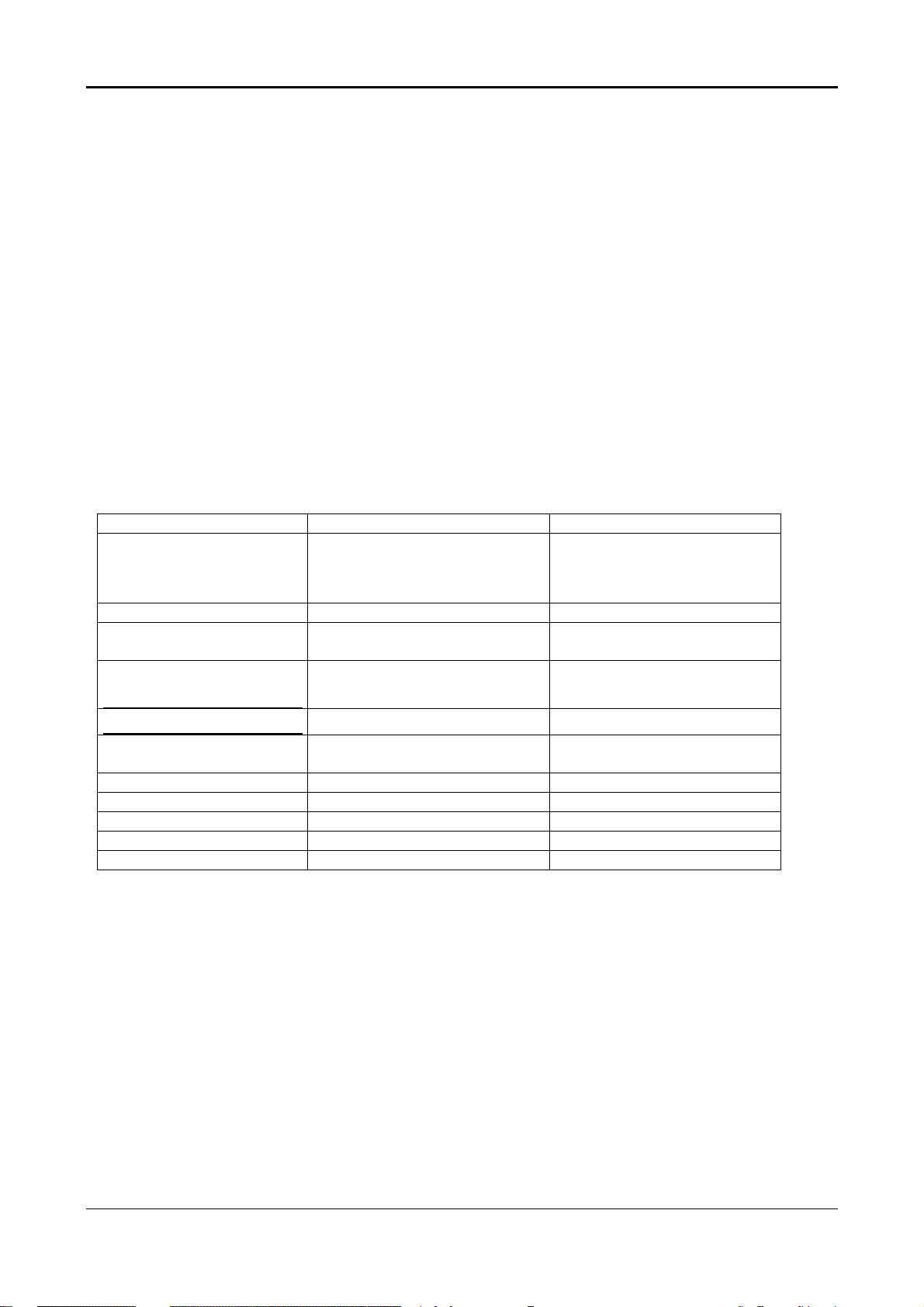
Comparison Chart of CML174SXW - CML175SXW
CML174SXW CML175SXW
Panel Normal 17” panel
AU M170EN05
Samsung LTM170EU-L02
Normal 17” panel
AU M170EN05
Samsung LTM170EU-L02
Signal Interface DSUB+DVI-D DSUB+DVI-D
Sync Type for analog
input
Color Temp user
Separate / compatible / Separate / compatible /
SUPPORT SUPPORT
adjust
DDC
Speaker No 1W+1W
Headphone Jack No Yes
Microphone Jack No No
USB Hub Not support Not support
Tilt / Swivel Yes / No Yes / No
Height Adjust Option Option
DDC2B DDC2B
3
2. ELECTRICAL REQUIREMENTS
2.1 Standard Test Conditions
All tests shall be performed under the following conditions, unless otherwise specified.
Ambient light: 225 lux
Viewing distance : 50 cm in front of LCD panel
Warrn up time
All specifications: 30 minutes
Fully functional: 5 seconds
Measuring Equipment: Chroma 2250 signal generator or equivalent, directly
Connected to the monitor under test.
Minolta CA100 photometer, or equivalent
Control settings
User brightness control: Maximum (unless otherwise specified )
User contrast control: Typical (unless otherwise specified )
User red/white balance,
Green/white balance and
Blue/white balance control: In the center (unless otherwise specified )
Power input : 110Vac or 230Vac
Ambient temperature : 20 ± 5 ˚C ( 68 ± 9 ˚ F)
Analog input mode : 1280 x1024 /60 Hz
2.1.1 MEASUREMENT SYSTEMS
The units of measure stated in this document are listed below:
1 gamma = 1 nano tesla
1 tesla = 10,000 gauss
cm = in x 2.54
lb = kg x 2.2
degrees F = [°C x 1.8] + 32
degrees C = [°F - 32]/1.8
u' = 4x/(-2x + 12y + 3)
v' = 9y/(-2x + 12y + 3)
x = (27u'/4)/[(9u'/2) - 12v' + 9]
y = (3v')/[(9u'/2) - 12v' + 9]
nits = cd/(m2) = Ft-L x 3.426
lux = foot-candle x 10.76
2.2 LCD monitor General specification
Panel Type : 17 “ active matrix color TFT LCD
1). AU 17” M170EN05
Display size : 337.92mm(H) x 270.34mm(V)
Display mode : VGA 720 X 400 (70 Hz)
VGA 640 X 480 (60/66/70/72/75 Hz)
SVGA 800 X 600 (60/70/72/75 Hz)
4

XGA 1024 X 768 (60/70/75 Hz)
SXGA 1280 X 1024 (60/70/75 Hz) standard resolution
Pixel pitch : 0.098x3mm(H) x 0.294mm(V)
Display Dot : 1280 x (RGB) x 1024
Pixel Clock : 25.2 – 135.0MHz
Contrast ratio:
Brightness: 260 cd/m
θ
400 : 1 (typical)
= 0˚
2
(typical)
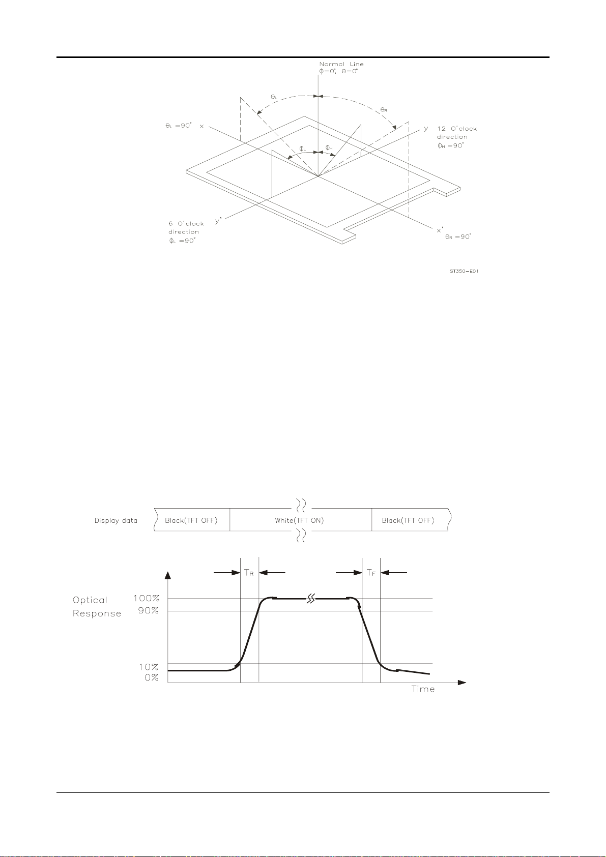
Response time (Tr/Tf) : 12 /4.0 msec
Display color : 16777216 (8 bite color)
Viewing angle: L / R • 80 / • 80 ( • 170 degrees horizontal typical)
U / D • 80 / • 80 ( • 170 degrees vertical typical)
Luminance Uniformity : > 80 %
Pc interface: 1). Video : RGB analog 0.7V peak to peak
Sync : TTL positive or negative
2). Digital TMDS
Signal connector : 15 pin Mini D type, (standard VGA video)
DVI-D connector
3.5 mm stereo audio jack(Audio)(CML175SXW)
3.5 mm miniature stereo Headphone jack(CML175SXW)
Audio power : 1Wrms + 1Wrms ( 300Hz – 10kHz (S.P.L. – 10 dB)) (CML175SXW)
Front control : power on/off with LED select (up, down) adjustment (+,-)
Interface frequency
y Horizontal Frequency 24KHz --80KHz(analog), 31.5– 80KHz(digital)
y Vertical Frequency 56Hz ----75Hz
Plug & play : Support VESA DDC2B functions
Power Input voltage : Single phase, 50/60HZ, 100VAC to 240VAC ±10%
Total output power : 48 Watt max.
2.3 LCD Panel Specification
2.3.1 LCD Panel Model (FUJITSU FLC48SXC8V)
•
Display Type active matrix color TFT LCD
•
Resolution 1280 x 1024 pixels
•
Display Dot 1280 x (RGB) x 1024
5
•
Display Area 337.92mm(H) x 270.34mm(V)
•
Pixel Pitch 0.264mm(H) x 0.264mm(V)
•
Display Color 262K (6 bit color)
•
Lamp Voltage 700 Vrms typ.
•
Lamp Current 7mA rms.( typ). 4 Lamp
•
Weight 2000g .
•
Optical Specifications
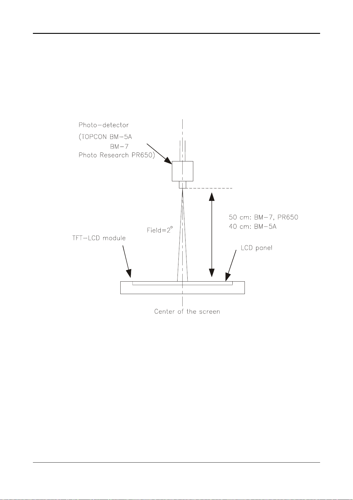
The following items are measured under stable conditions. The optical characteristics
should be measured in a dark room or equivalent state with the methods shown in
Note(4).
Measuring equipment : TOPCON BM-5A, BM-7, PHOTO RESEARCH PR650
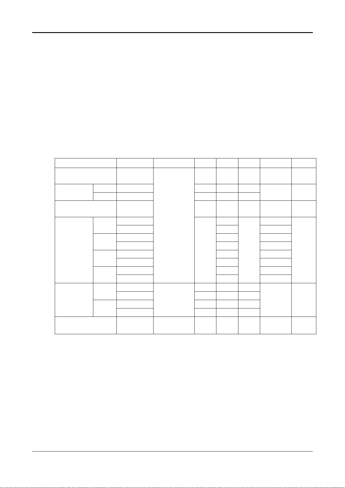
(Inverter Freq. : 54kHz) *Ta =25 ± 2°C, VDD=5V, fv=60 Hz, fDCLK=54 MHz, IL= 6.5mArms
Item Symbol Condition Min. Typ. Max. Unit Note
Contrast Ratio
(Center of screen)
Response
Time
Luminance of White
(Center of screen)
Color
Chromaticity
(CIE 1931)
Viewing
Angle
Brightness Uniformity
(9 points)
Rising TR - 12 20
Falling T
Red
Green
Blue
White
Hor.
Ver.
CR
F
- 4.0 5
L
Y
Rx 0.64
Ry 0.34
Gx 0.29
Gy 0.61
Bx 0.14
By 0.07
Wx 0.31
Wy
θ
L
θ
R
φ
H
φ
L
UNI
B
Normal
φ
= 0˚
θ
= 0˚
Viewing
Angle
CR≥5
75 - -
250 400 -
200 260 -
TYP.
-0.03
0.33
70 80 -
70 80 -
70 80 -
70 80 -
TYP.
+0.03
msec
cd/m2
Degrees
%
(1)(2)(4)
BM-5A
(1)(3)
BM-7
(5)
BM-5A
(1)(4)
PR650
(1)(4)
BM-5A
(6)
BM-5A
6
Note 1) Definition of Viewing Angle: Viewing angle range (10≤CR)
Note 2) Definition of Contrast Ratio (CR): Ratio of gray max(Gmax),gray min(Gmin) at the
center point of panel.
Luminance with all pixels white (Gmax)
CR=
Luminance with all pixels black (Gmin)
Note 3) Definition of Response time: Sum of TR , TF
7
Note 4) After stabilizing and leaving the panel alone at a given temperature for 30 min, the
measurement should be executed .Measurement should be executed n a stable,
windless ,and dark room.30 min after lighting the back-light. This should be
measured in the center of screen. Dual lamp current :13.0mA(6.5mA x2)(Refer to
the note(1) in the page 14 for more information ).
Environment condition :Ta=25±2°C
Optical characteristics measurement setup
8
Notes 5) Definition of Luminance of White : measure the luminance of white at center point.
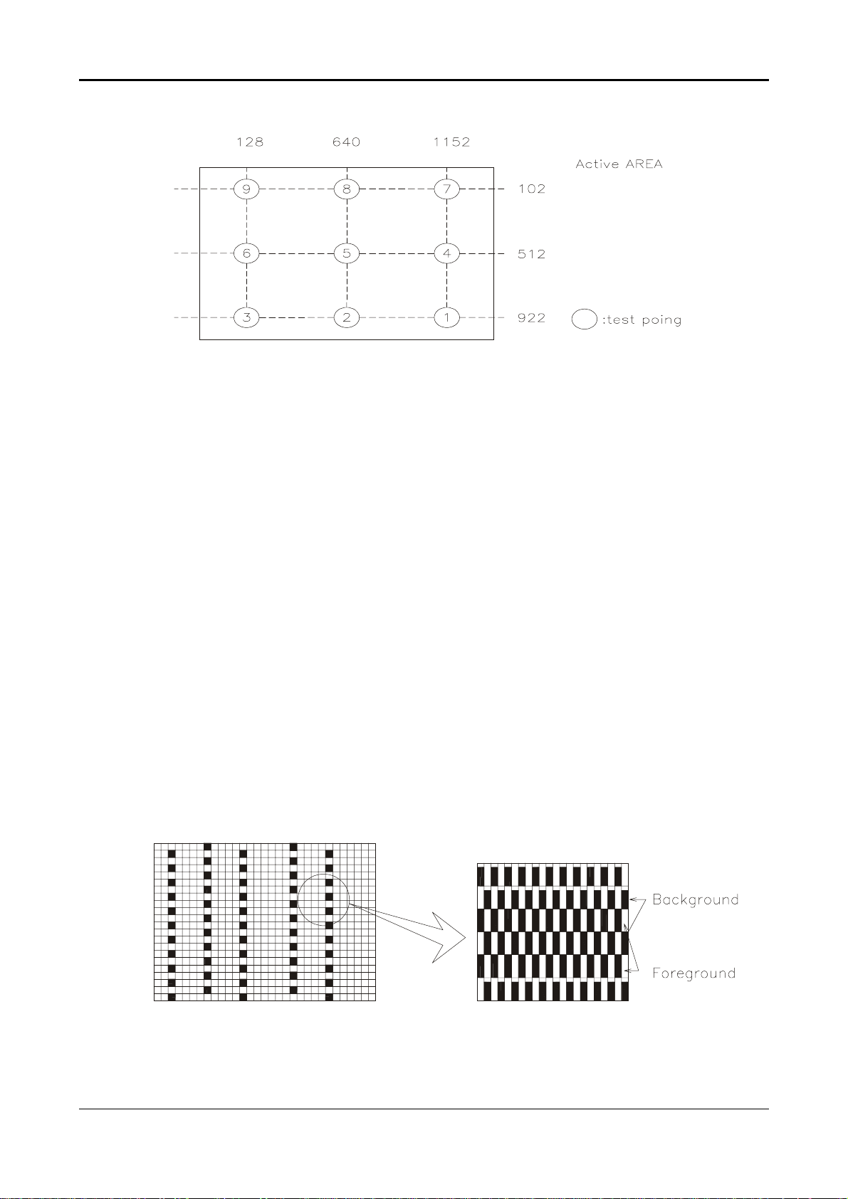
Notes 6)Definition of 9 points brightness uniformity (Measuring points: Refer to the Note 5)
Bmin
B
=100∗∗∗∗
UNI
Bmax
Bmax: Maximum brightness
Bmin: Minimum brightness
Notes 7) Definition of Flicker level
Flicker Voltage
pp
F = x 100 %
LMD Voltage
♦
♦ One maximum value of three estimated values.
♦♦
♦
♦ For this test ,an LMD(Light Measurement Device)is needed with adequate response time
♦♦
dc
to track any visible rate flicker component and with a voltage level output proportional
To luminance intensity.
♦
♦ Test Pattern: For dot inversion Driving(Gray levels of foreground dots on the test panel
♦♦
Are G22,G32,and G45)
♦
♦ Test Point :Center point of the display area
♦♦
9
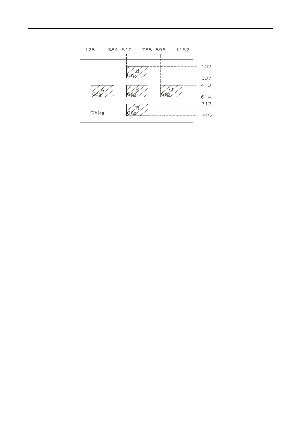
Note 8) Definition of Crosstalk (Refer to the VESA STD)
The calculation for shadowing is made from the 2 luminance measurements Gbkg and Lsh,
as follows:
Lmax -Lmin
C
= x100 %
T
Lmin
Where Lmax is the larger value of Gbkg or Lsh , and Lmin is the smaller of the two.
♦ To determine background and foreground levels (colours),first set the background to any
gray scale or color level suitable for shadowing determination.(Note that it may take
several iterations of adjusting background level and box levels to determine the proper
value for the background .Next display the box levels to determine the proper value for the
background level. Look for shadowing in any direction from box E. Independently vary the
gray level (or color) of the background and box E until the worst case shadowing is
observed. This defines the background (Gbkg) and foreground (Gfg) levels to be
maintained for the remainder of the test.
♦ One point only (the target) will be measured. To determine that point proceed as follows
Using the background and foreground gray levels of step1 (Gbkg and Gfg). Turn on each
box at a time. Look for the case with the worst shadowing. The box causing the worst case
is the shadowing source, or Bsrc. Use Bsrc and the box opposite from it that lies directly in
the shadow path. That is the target box, or Btgt. Note that box Eight be either Bsrc or Btgt,
depending on the shadowing conditions, but typically Bsrc and Btgt will be a pair of
opposite boxes, A&C or B&D. Btgt will only be displayed for aligning the LMD. It will be
turned off for the actual measurement.
♦
♦ The target box point (Btgt) will be measured with the source box (Bsrc) turned on then off.
♦♦
(Btgt is for alignment purpose only) Display the background only at level Gbkg. Display
Btgt determined in step 2 above. Using the correct distance, angle, and measurement
aperture, align the LMD to the center of the Btgt. Turn off Btgt. With Gbkg set to its proper
level, measure the luminance (or color). Next,turn on the source box Bsrc. Again measure at
the center point of Btgt (without Btgt present.). In this case the LMD will be measuring the
shadowing level, Lsh.
10
2.4 Input Signals
2.4.1 Video input
•
Type Analog R, G, B., Digital TMDS
•
Input Impedance 75 ohm +/- 2%
•
Polarity Positive
•
Amplitude 0 - 0.7 +/- 0.05 Vp
•
Display Color same as LCD panel
2.4.2 Sync input
•
Signal separate horizontal and vertical sync, or composite sync
•
Polarity positive and negative.
2.4.3 Interface frequency
The following frequency range is generalized by supported timing. If the entered
mode does not match the supported timing the display optimization will not be
which are TTL compatible
assured.
•
Horizontal Frequency 24KHz --80KHz(analog), 31.5– 80KHz(digital)
•
Vertical Frequency 56Hz ---------75Hz
DISPLAY MODES
MONITOR
MODE NO.
1 640x350 31.5 + 70.0 - 25.0 VGA
2 640X400 24.83 - 56.4 - 21.05 NEC
3 640X400 31.5- 70.0+ 25.0 VGA
4 640X400 31.5- 70.1- 25.19 NEC
5 640X480 31.5 - 60.0 - 25.0 Defacto
6 640X480 35.0- 66.67- 30.24 MAC
7 640X480 37.86- 72.80- 31.5 VESA
8 640X480 37.5- 75.0- 31.5 VESA
9 720X400 31.5 - 70.0 + 28.0 Text Defacto
10 832X624 49.72- 74.55 - 57.28 MAC
11 800X600 35.16+ 56.25+ 36.0 SVGA
12 800X600 37.8 + 60.0 + 40.0 VESA
13 800X600 48.07 + 72.18 + 50.0 VESA
14 800X600 46.87+ 75.0+ 49.5 VESA
15 1024X768 48.4 - 60.0 - 65.0 VESA
16 1024X768 53.96 + 66.13 + 71.66 XGA
17 1024X768 56.47 - 70.07 - 75.0 VESA
18 1024X768 60.0 + 75.0 + 78.75 VESA
19 1024x768 60.24- 75.02- 80.0 MAC-768
20 1280X1024 64.0 + 60.0 + 108.5 SXGA
21 1280X1024 80.0 + 75.0 + 135.0 Defacto
SCREEN
RESOLUTION
HORIZONTAL
SYNC RATE
(kHz)
VERTICAL
SYNC RATE
(Hz)
VIDEO CLK
(MHz)
STANDARD
11
Supported Timing
TIMING
FV(HZ) POLARITY (DOT/LINE) (DOT/LINE) WIDTH PORCH PORCH FOREQ.(MHZ)
(DOT/LINE) (DOT/LINE) (DOT/LINE)
640x350 31.469 + 800 640 96 16 48 25.175
VGA-350 70.087 – 449 350 2 37 60
640x400 24.83 – 848 640 64 64 80 21.05
NEC PC9801 56.42 – 440 400 8 7 25
640x400 31.469 – 800 640 96 16 48 25.175
VGA-GRAPH 70.087 + 449 400 2 12 35
640x400 31.5 – 800 640 64 16 80 25.197
NEC PC9821 70.15 – 449 400 2 13 34
640x480 31.469 – 800 640 96 16 48 25.175
VGA-480 59.94 – 525 480 2 10 33
640x480 35.00 – 864 640 64 64 96 30.24
APPLE MAC480
640x480 37.861 – 832 640 40 16 120 31.5
VESA-480-72Hz 72.809 – 520 480 3 1 20
640x480 37.5 – 840 640 64 16 120 31.5
VESA-480-75Hz 75 – 500 480 3 1 16
720x400 31.469 – 900 720 108 18 54 28.322
VGA-400-TEXT 70.087 + 449 400 2 12 35
832x624 49.725 – 1152 832 64 32 224 57.2832
APPLE MAC800
800x600 35.156 + 1024 800 72 24 128 36
SVGA 56.25 + 625 600 2 1 22
800x600 37.879 + 1056 800 128 40 88 40
VESA-600-60Hz 60.317 + 628 600 4 1 23
800x600 48.077 + 1040 800 120 56 64 50
VESA-600-72Hz 72.188 + 666 600 6 37 23
800x600 46.875 + 1056 800 80 16 160 49.5
VESA-600-75Hz 75 + 625 600 3 1 21
1024x768 48.363 – 1344 1024 136 24 160 65
XGA 60.004 – 806 768 6 3 29
1024x768 53.964 + 1328 1024 176 16 112 71.664
COMPAQ-XGA 66.132 + 816 768 4 8 36
1024x768 56.476 – 1328 1024 136 24 144 75
VESA-768-70Hz 70.069 – 806 768 6 3 29
1024x768 60.023 + 1312 1024 96 16 176 78.75
VESA-768-75Hz 75.029 + 800 768 3 1 28
1024x768 60.24 – 1328 1024 96 32 176 80
APPLE MAC768
1280x1024 64 + 1688 1280 112 48 248 108
VESA-102460Hz
1280x1024 80 + 1688 1280 144 16 248 135
VESA-102475Hz
If the input timing is not a supported timing listed above but within the supported frequency
range (Horizontal: 80KHz,Vertical: 75Hz), this monitor will select a closest mode instead. But
the display quality may not be optimized.
If the input timing over the supported frequency range, a message “Input Signal Out of Range”
will be shown.
FH(KHZ) SYNC TOTAL ACTIVE SYNC FRONT BACK PIXEL
66.67 – 525 480 3 3 39
74.55 – 667 624 3 1 39
75.02 – 803 768 3 3 29
60 + 1066 1024 3 1 38
75 + 1066 1024 3 1 38
12
2.4.4 85Hz refresh rate Support
Monitor should display 85Hz refresh rate mode as emergency mode.
Monitor should display “Out of Range” warning menu at this mode.
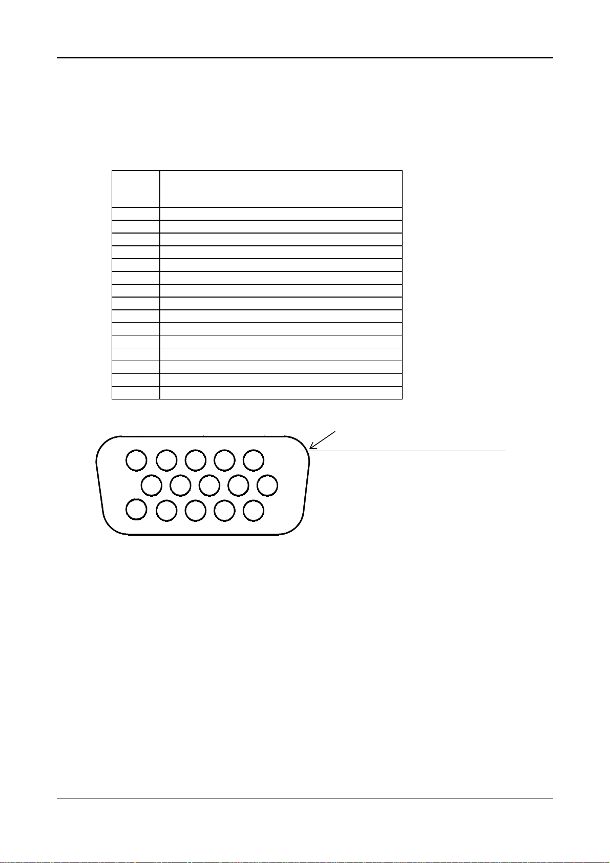
2.4.5 Video input Connector
Analog Video input Connector: 15pins mini D-Sub
Table 2.4.5. Pin assignment for D-sub connector
PIN
NO.
1 RED VIDEO
2 GREEN VIDEO
3 BLUE VIDEO
4 GROUND
5 GROUND
6 RED GROUND
7 GREEN GROUND
8 BLUE GROUND
9 PC5V (+5V DDC)
10 CABLE DETECTION
11 GROUND
12 SDA
13 H.SYNC
14 V.SYNC
15 SCL
Separate Sync
Color of plastic parts: Blue (PC99)
5 1
10
15
D-sub connector
6
11
13
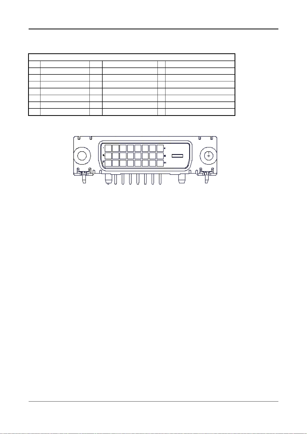
Digital Video input Connector: DVI-D (T.B.D)
Table 4-3-3. Pin assignment for DVI-D (24pin) connector
Pin – Assignment of DVI –D connector :
1 TX2- 9 TX1- 17 TX0-
2 TX2+ 10 TX1+ 18 TX0+
3 Shield (TX2 / TX4) 11 Shield (TX1 / TX3) 19 Shield (TX0 / TX5)
4 NC 12 NC 20 NC
5 NC 13 NC 21 NC
6 DDC-Serial Clock 14 +5V power *) 22 Shield (TXC)
7 DDC-Serial Data 15 Ground (+5V) 23 TXC+
8 No Connect 16 Hot plug detect 24 TXC-
*) In case, the power of the PC unit is switched off and the power of the monitor is switched on,
no voltage may occur at pin 14.
14
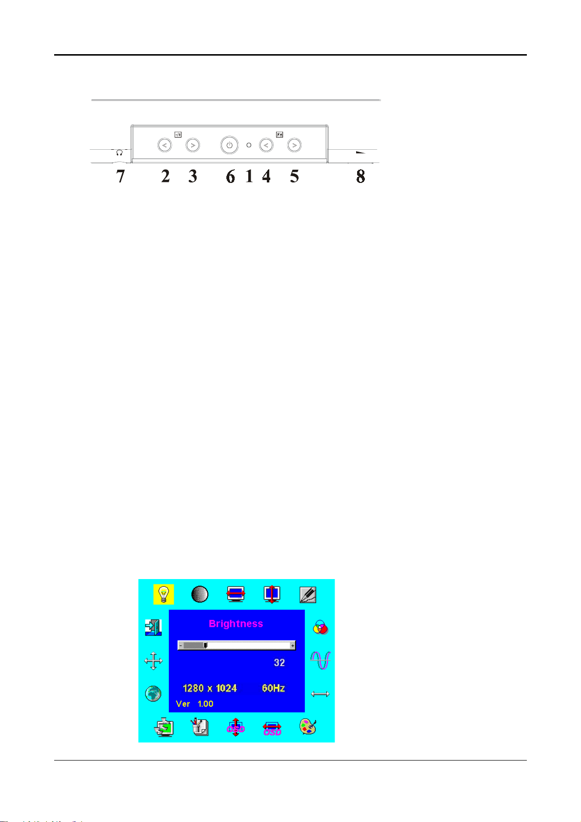
2.5 CONTROLS
2.5.1 Control panel (monitor front panel)
1. Power LED, will be green when monitor is on; be amber when in power saving mode.
2. Adjust decrease.
3. Adjust increase.
4. Function select counter-clockwise.
5. Function select clockwise.
6. Power ON/OFF switch, push to ON and push to OFF. (toggle switch)
7. Ear phone jack. (CML175SXW only)
8. Volume Control. (CML175SXW only)
Note: When OSD Menu is off, press button 2 and 3 at the same time can activate “Auto
Adjustment” immediately.
2.5.2 OSD Functions
•
OSD Format: Refer to following figure.
•
OSD Border: Cyan color
•
OSD Tunable Item: The 16 icons that around the border.
•
Selected Item: Yellow background
•
Comment: Magenta foreground, Blue background
page format :
15

Description:
•
•
•
•
•
•
•
•
•
Brightness: Brightness adjustment, the range from 0 to 100. Default = 100
Contrast: Contrast adjustment, the range from 0 to 100. Default = 50
H. Position: Horizontal position adjustment.
V. Position: Vertical position adjustment.
Phase: Focus adjustment, the range from 0 to 255 steps.
OSD position: OSD position adjustment.
Auto Adjustment: This feature will automatically adjust size, position, clock and phase.
It takes 3-5 seconds to finish. When auto start, it shows “Auto
Adjusting….” message.
Clock: Frequency tracking adjustment. The max range from -50 to +50, but
some modes the range will be limited.
Graph Text: 640x400(GRAPH) or 720x400(TEXT) mode select.
•
Language: 5 kinds of language for description, including (English, German,
French, Spanish, Italian)
•
Recall: Recall the default value.
•
Color Temp: Color temperature for standard 9300,6500, 7500 or user defined.
User:
User R: Red signal gain by user defined.
User G: Green signal gain by user defined.
User B: Blue signal gain by user defined.
7500: Set CIE coordinate at 7500°K color temperature.
6500: Set CIE coordinate at 6500°K color temperature.
9300: Set CIE coordinate at 9300°K color temperature.
•
Exit: Exit OSD menu function.
Sharpness : Adjust the scale-up effect(smoother or sharper.)
OSD Transparency: Adjust the transparency level of OSD. The range is from 0 to 100 scales.
Comment:
•
•
•
1280x1024: Current mode resolution.
60 HZ: Current mode vertical frequency±1Hz.
VER 1.00: Firmware revision.
16
z Other features:
Intellectual-Auto CML174SXW/175SXW can start the Auto-Adjustment automatically when
input a new display mode at first time. After the adjustment, CML174SXW/175SXW will
remember this mode and switch to optimized condition automatically for this mode
whenever encounter this mode again. Total 27 recent used modes are recorded into
CML174SXW/175SXW
VESA DPMS Functionality When signaled by the host CPU, CML174SXW/175SXW
show a black screen about 3 seconds. If no further signal, then it shows “No Signal” and
enter power saving mode.
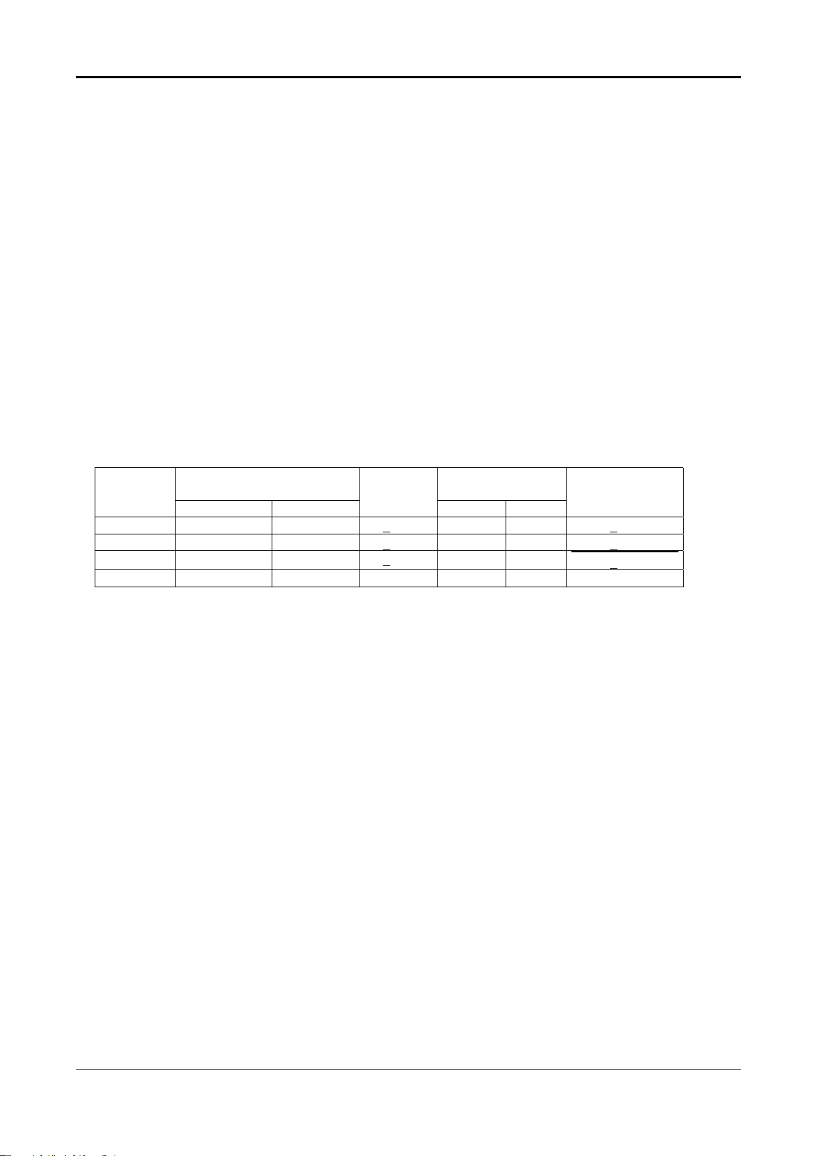
2.6 White Color Temperature
White color temperature is 4 preset as 9300, 7500,6500 and User,
Default value of user color should be user which is maximum setting for panel.
Target of color setting
Color
Temp.
9300K 0.281 0.297 +0.03 0.189 0.446 u’v’ < 0.01*
7500K 0.299 0.315 +0.03 0.194 0.459 u’v’ < 0.01*
6500K 0.313 0.329 +0.03 0.198 0.469
User - - - - -
User should follow “Microsoft Windows Color Quality Specification for Liquid Crystal Display OEM’s”.
(http://www.microsoft.com/hwdev/tech/color/ColorTest.asp)
Color Coordinate Tolerance Color Coordinate Tolerance
x y u’ v’
*) TCO’0X A.2.6.1 requirement
u’v’ <
0.01*
17
2.7 POWER SUPPLY
2.7.1 input Voltage Range
The monitor shall operate within specification over the range of 90 to 265 VAC power supply.
2.7.2 Input Frequency Range
Input power frequency range shall be from 47.5 to 63 Hz over the specified input
voltage range.
2.7.3 Quick specification review
•
Input current
1.2A (max) at 90VAC input and full load ,
0.6A (max) at 264 VAC input and full load.
•
Inrush current @ cold start
30A(0-peak)@ 110Vac ,50A(0-peak) @ 220Vac
(measured when switched off for at least 10 mins.)
•
Output
Tolerance Output Current
Output Volt - MIN MAX
+5Vdc ±5% 0A 1.0A 4.8~5.2V dc
+5Vdc ±5% 0A 1.5A 4.8~5.2V dc
+12Vdc ±5% 0A 2.2A 11.4~12.6Vdc
•
Total output power: 48 Watt max.
•
Withstanding voltage : 1.5Kvac or 2.2KVdc for 1 minute.
•
Leakage current : < 0.25mA/100Vac , <3.5mA/230Vac
•
Efficiency : 80% min. @115V/230VAC, maximum load.
2.7.4 Power Management
2.7.4.1 Meet VESA DPMS proposal
The monitor must comply with the Microsoft On Now specification, with a minimum of three power
management states, as defined by the VESA DPMS document. The front panel of the monitor must
appropriately display the DPMS state, For example:
DPMS ON : The power LED is Green
DPMS OFF : The power LED is Amber
Volt Tolerance
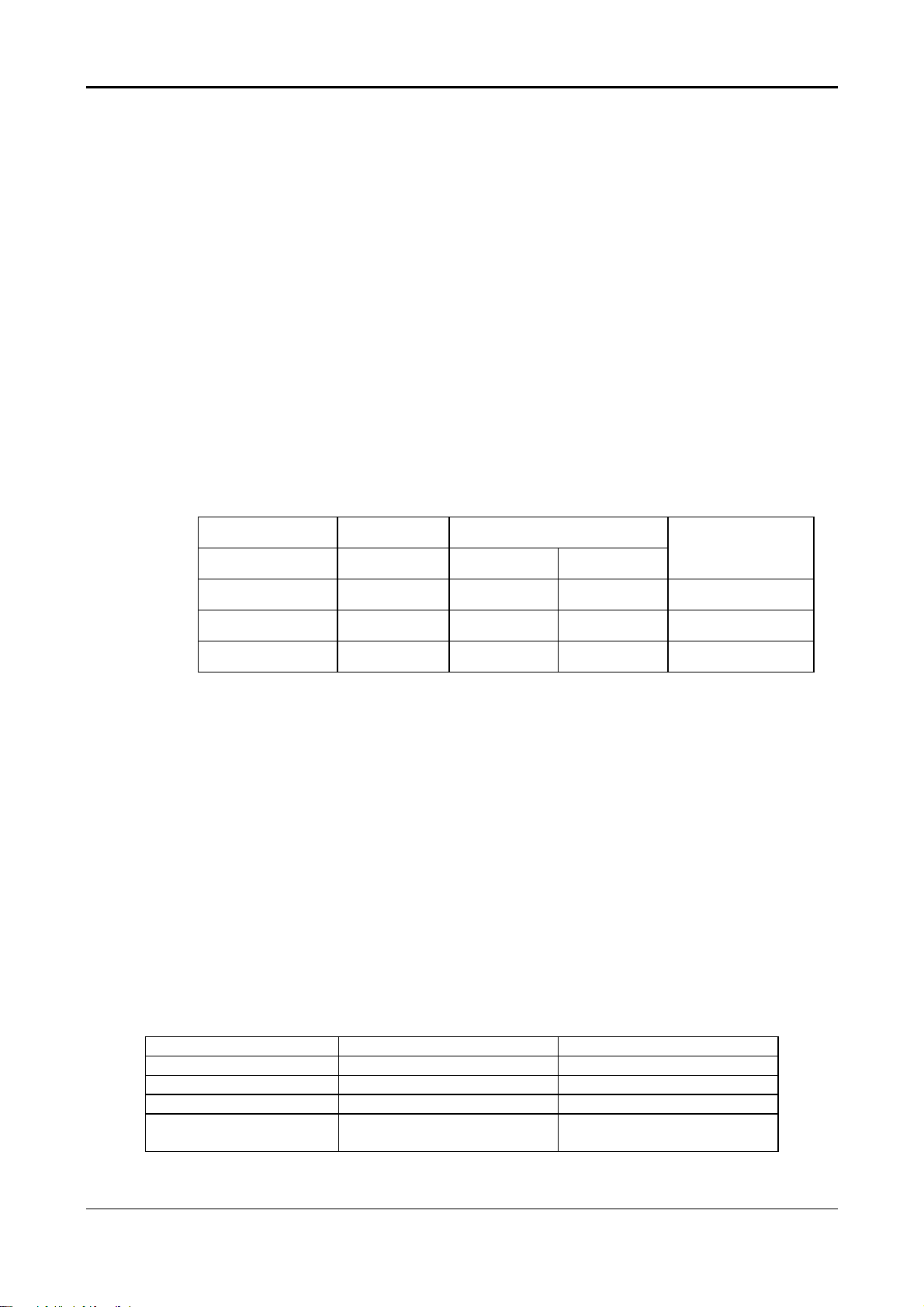
2.7.5 Power Consumption
On mode 48 Wmax Green
Off mode 3 Wmax Amber
DC power off 3 Wmax Dark
Power SW off 1 Wmax Dark
disconnection 3 Wmax
Power saving states are measured with speakers attached but not worked.
The recovery time from stand by /suspend/off mode to on mode is 3 seconds maximun.
Dark (DC power off)
Amber (DC power on)
18
 Loading...