

Page 1
CH-UNIT
ENGLISH
INSTALLATION AND OPERATION MANUAL
MANUAL DE INSTALACIÓN Y FUNCIONAMIENTO
INSTALLATIONS- UND BETRIEBSHANDBUCH
MANUEL D’INSTALLATION ET DE
FUNCTIONNEMENT
MANUALE D’INSTALLAZIONE E D’USO
MANUAL DE INSTALAÇÄO E DE
FUNCIONAMENTO
BRUGER- OG MONTERINGSVEJLEDNING
INSTALLATIE- EN BEDIENINGSHANDLEIDING
HANDBOK FÖR INSTALLATION OCH ANVÄNDING
ΕΓΧΕΙΡΙΔΙΟΕΓΚΑΤΑΣΤΑΣΗΣΚΑΙΛΕΙΤΟΥΡΓΙΑΣ
MODELS:
CH-4.0NE
CH-8.0NE
CH-12.0N
ESPAÑOL
DEUTCH
FRANÇAIS
ITALIANO
PORTUGUESDANSK
Do not perform installation work, without referring to our installation manual.
No realice la instalación de este equipo, sin antes consultar este manual de instalación.
Bei der Installation unbedingt die Hinweise in der Installationsanleitung beachten.
Consulter notre manuel avant de réaliser une quelconque installation.
Realizzare l’installazione, seguendo quanto indicato in questo manuale.
Nao inicie os trabalhos de montagem, sem consultar o nosso manual de montagem.
Udfor ikke installationsarbejder uden forst at donsultere vores vejledning.
Voer geen enkele handeling uit om de apparatuur alvorens deze hadleiding te hebben
doorgelezen.
Utför inte nagra installationsarbeten utan att först läsa var installationsmanual
Μην ήσετε στην εγκατάσταση, χωρίς πριν να έχετε συμβουλευθεί αυτo το εγχειρίδιο εγκατάστασης
NEDERLANDS
SVENSKA
Page 2

Page 3

Specifications in this catalogue are subject to change without notice in order that
HITACHI may bring the latest innovations to their custo me rs
Whi lst ever y effort is m ade to en sure that all dimensions and specifi catio ns are c or rect,
any printers' errors not rectified are outside the control of HITACHI, who cannot be held
responsible for same
Page 4

Page 5
DANGER – Immediate hazard which WILL result in severe injury or death.
Õ
PELIGRO – Riesgos inmediatos que PRODUCIRÁN lesiones personales graves e incluso
la muerte.
GEFAHR – Unmittelbare Gefahrenquellen, die zu schweren Verletzungen oder zum Tod
führen.
DANGER – Dangers instantanés de blessures corporelles sévères ou de mort.
PERICOLO – Pericolo immediato che PRODURRÀ ferite gravi o la morte.
PERIGO – Problemas imediatos que IRÃO resultar em graves ferimentos pessoais ou
morte.
FARE – Overhængende fare, som VIL resultere i alvorlig personskade eller dødsfald.
GEVAAR – Onmiddellijke risico's die ernstige persoonlijke verwondingen of de dood ten
gevolge kunnen hebben.
FARA – Omedelbar risk som medför svår personskada eller död.
KINAYNO – Άµεσος κίνδυνος που ΘΑ έχει ως αποτέλεσµα σοβαρές σωµατικές βλάβες ή
θάνατο.
WARNING – Hazards or unsafe practices which COULD result in severe personal injuries
Ô
or death.
AVISO – Riesgos o prácticas poco seguras que PODRÍAN producir lesiones personales e
incluso la muerte.
WARNUNG – Gefährliche oder unsichere Anwendung, die zu schweren
Körperverletzungen oder zum Tod führen kann.
ATTENTION – Utilisation dangereuse ou sans garantie de sécurité qui PEUT provoquer de
sévères blessures personnelles ou la mort.
AVVISO – Pericoli o azioni pericolose che POTREBBERO avere come esito lesioni fisiche
gravi o il decesso.
AVISO – Riesgos o prácticas poco seguras que PUEDEN producir lesiones personales e
incluso la muerte
ADVARSEL – Farer eller farlig brug, som KAN resultere i alvorlig personskade eller
dødsfald.
WAARSCHUWING – Gevaren of onveilige praktijken die ernstig persoonlijk letsel of de
dood tot gevolg KUNNEN hebben.
VARNING – Risker eller osäkra tillvägagångssätt som KAN leda till svåra personskador
eller dödsfall.
ΠΡΟΕΙ∆ΟΠΟΙΗΣΗ – Κίνδυνοι ή επικίνδυνες πρακτικές, οι οποίες ΜΠΟΡΕΙ να έχουν ως
αποτέλεσµα σοβαρές σωµατικές βλάβες ή θάνατο.
ESPAÑOLDEUTSCHFRANÇAISPORTUGÊSDANSKNEDERLANDSSVENSKA ITALIANOEΛΛHNIKA ENGLISH
CAUTION – Hazards or unsafe practices which COULD result in minor personal injury or
product or property damage.
PRECAUCIÓN – Riesgos o prácticas poco seguras que PODRÍAN provocar lesiones
personales de menor importancia o daños en el producto u otros bienes.
VORSICHT – Gefährliche oder unsichere Anwendung, die geringfügigen Personen-,
Produkt- oder Sachschaden verursachen kann.
PRECAUTION – Utilisation dangereuse ou sans garantie de sécurité qui PEUT provoquer
des blessures mineures ou des dommages au produit ou aux biens.
ATTENZIONE – Pericoli o azioni pericolose che POTREBBERO avere come esito lesioni
fisiche minori o danni al prodotto o ad altri beni.
CUIDADO – Perigos e procedimentos perigosos que PODERÃO PROVOCAR danos
pessoais ligeiros ou danos em produtos e bens.
FORSIGTIG – Farer eller farlig brug, som KAN resultere i mindre skade på personer,
produkt eller ejendom.
LET OP – Gevaren of onveilige praktijken die licht persoonlijk letsel of beschadiging van
het product of eigendommen tot gevolg KUNNEN hebben.
VARSAMHET – Risker eller farliga tillvägagångssätt som KAN leda till mindre
personskador eller skador på produkten eller på egendom.
ΠΡΟΣΟΧΗ – Κίνδυνοι ή επικίνδυνες πρακτικές, οι οποίες ΜΠΟΡΕΙ να έχουν ως
αποτέλεσµα την πρόκληση ελαφρών σωµατικών βλαβών ή καταστροφή περιουσίας.
Page 6

Page 7
SAFETY SUMMARY
1. SAFETY SUMMARY
Ô WARNING:
- Do not perform installation work, refrigerant piping work and electrical wiring connection
without referring to our installation manual.
- Check that the ground wire is securely connected.
- Connect a fuse of specified capacity.
CAUTION:
- Do not install the CH unit and cable within approximately 3 meters from strong
electromagnetic wave radiators such as medical equipment.
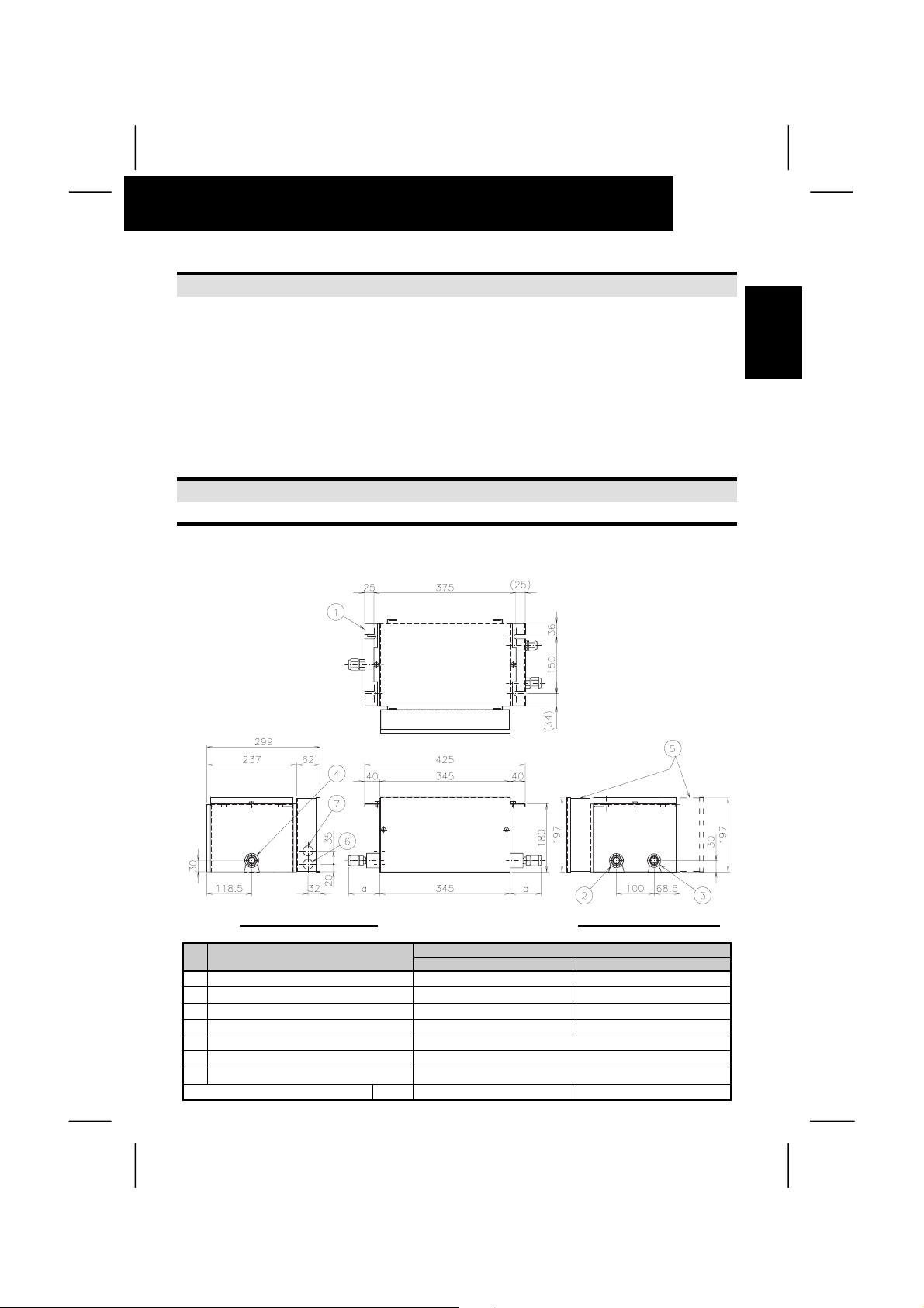
2. STRUCTURE
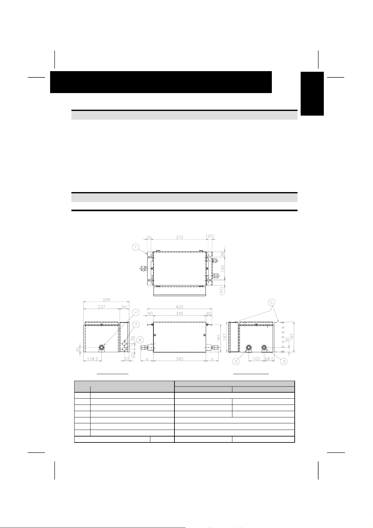
2.1. DIMENSIONS
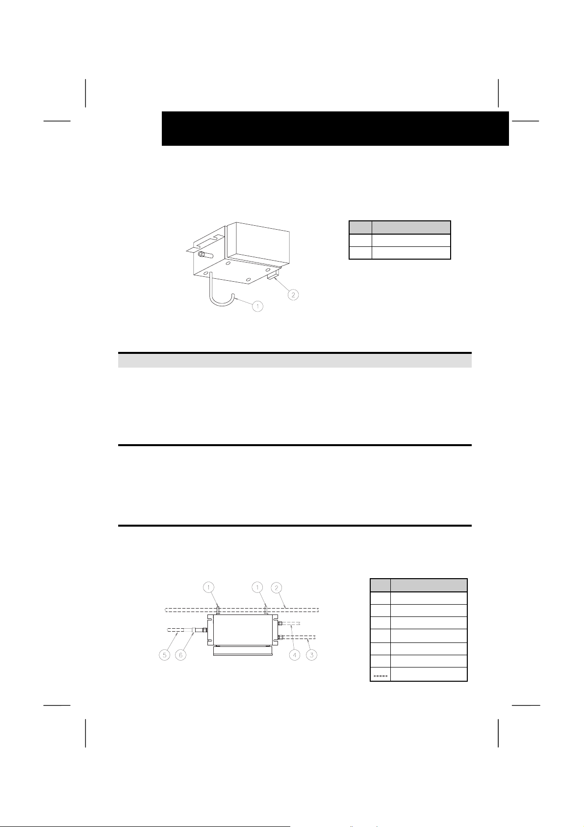
2.1.1. Model: CH Unit – CH-(4.0/8.0)NE
1
ENGLISH
Unit:mm
To Indoor Unit To Outdoor Unit
No Description
1 Suspension Bracket For M8 or W5/16 Bolt
2 Refrigerant Gas (Low) Pipe connection
3 Refrigerant Gas (High) Pipe connection
4 Refrigerant Gas Pipe connection
5 Electrical Control Box (Available attachment in the both sides)
6 Hole for operating Line
7 Hole for power supply Line
Dimension a 78mm 82mm
CH-4.0NE CH-8.0NE
∅15.88 Flare connection ∅19.05 Flare Connection
∅12.7 Flare connection ∅15.88 Flare Connection
∅15.88 Flare connection ∅19.05 Flare connection
Remarks
∅26.5
∅26.5
Page 8
2
STRUCTURE
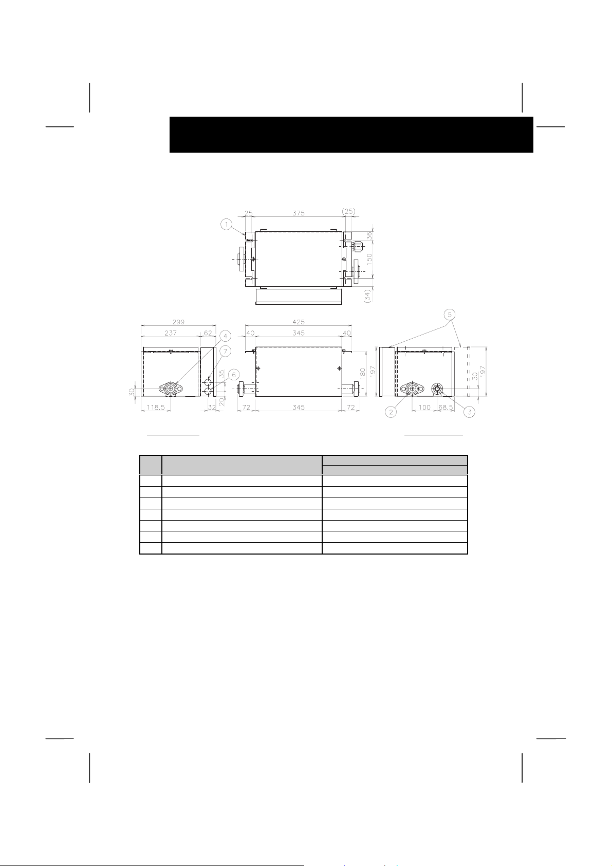
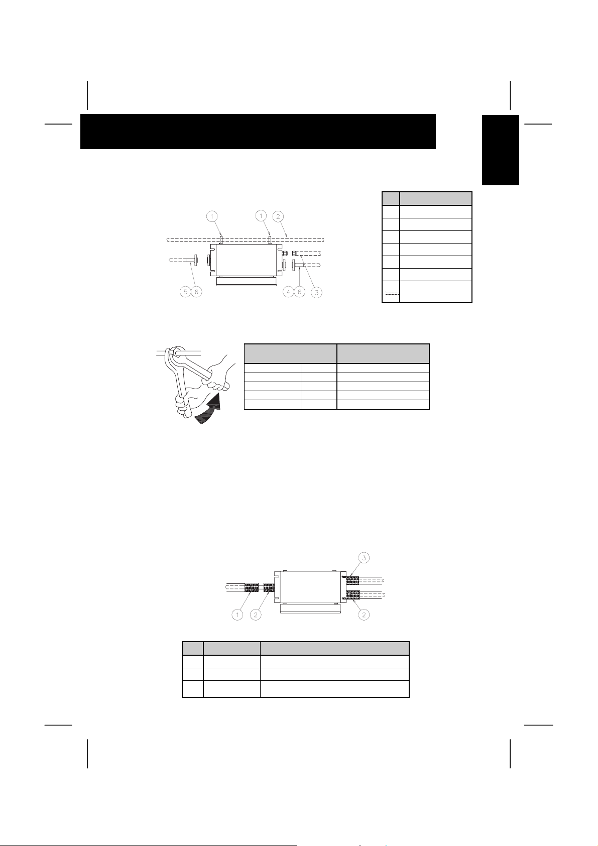
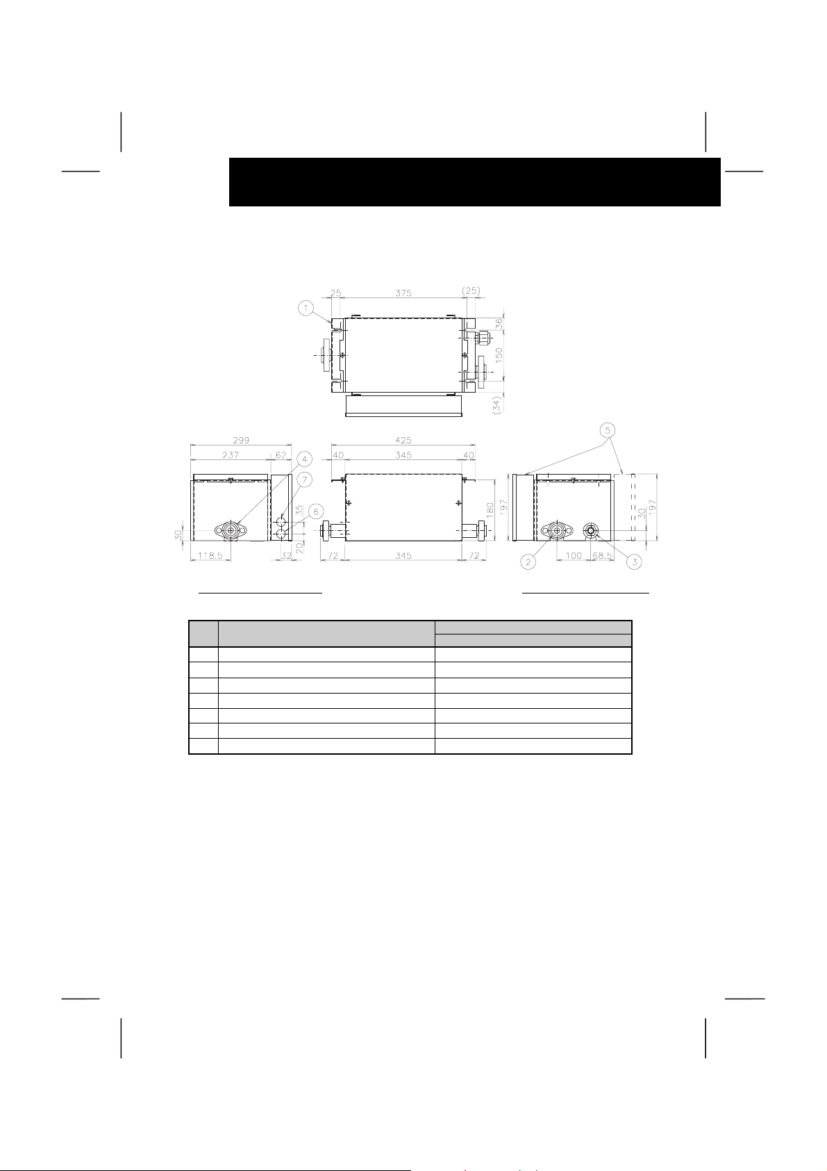
2.1.2. Model: CH Unit – CH-12.0N
To Indoor Unit To Outdoor Unit
Unit:mm
No Description
1 Suspension Bracket For M8 or W5/16 Bolt
2 Refrigerant Gas (Low) Pipe connection
3 Refrigerant Gas (High) Pipe connection
4 Refrigerant Gas Pipe connection
5 Electrical Control Box (Available attachment in the both sides)
6 Hole for operating Line
7 Hole for power supply Line
Remarks
CH-12.0N
∅22.2 Flange connection
∅19.05 Flare connection
∅22.2 Flange connection
∅26.5
∅26.5
Page 9
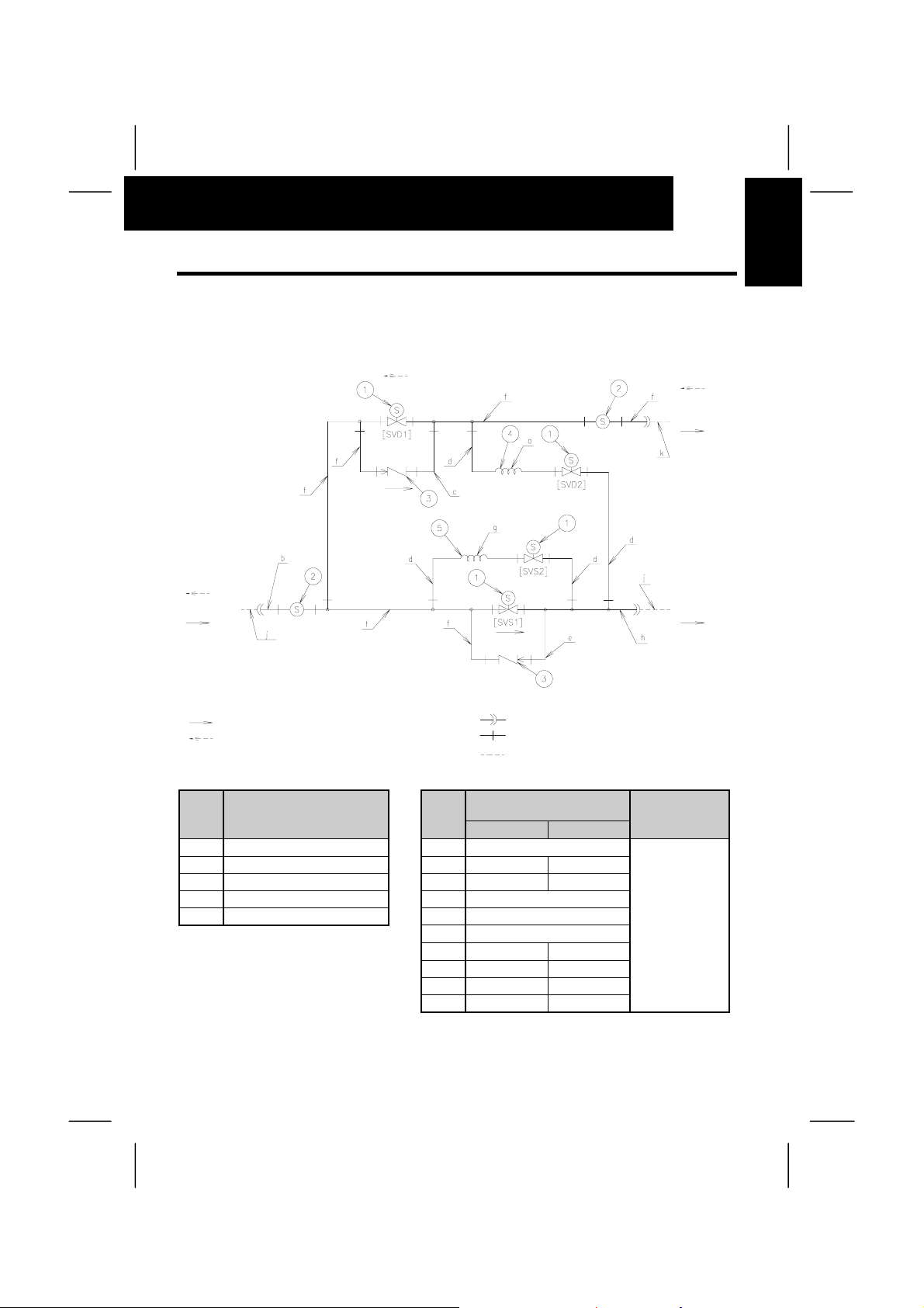
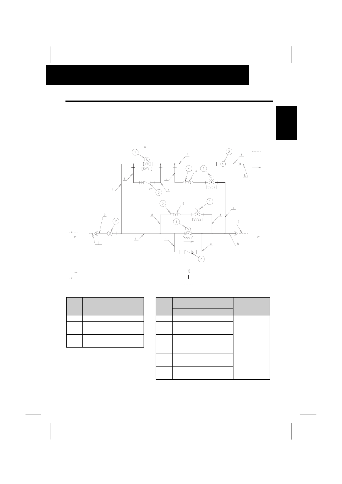
2.2. REFRIGERANT CYCLE
2.2.1. CH Unit - CH-(4.0/8.0)NE
To Indoor Unit To Outdoor Unit
Õ
High
Pressure
Gas Line
STRUCTURE
High Pressure
3
ENGLISH
Ö
Gas Line
Low
Pressure
Gas Line
Low
Pressure
Gas Line
Refrigerant Flow Direction (Cooling Operation)
Refrigerant Flow Direction (Heating Operation)
No Description Mark
1 Solenoid Valve (AC) a
2 Strainer b
3 Check Valve c
4 Capillary Tube d
5 Capillary Tube e
O.D.(mm) × thickness (mm)
CH-4.0NE CH-8.0NE
∅12.7×1.0 ∅15.88×1.0
∅9.53×0.8 ∅12.7×1.0
f
g
h
∅12.7×1.0 ∅15.88×1.2
j
k
NOTE:
The mark of inside "[ ]" is shown in the electrical wiring diagram.
Flare Connection
Brazing Connection
Field Refrigerant Piping
Material Size
∅2.5x0.7
∅6.35×1.07
∅9.53×0.8
∅12.7×1.0
∅4.0x0.8 ∅4.0x0.5
∅15.88 ∅19.05
∅12.7 ∅15.88
Low
pressure
gas line
Material
Copper Tube
C1220T-O
Page 10

4
STRUCTURE
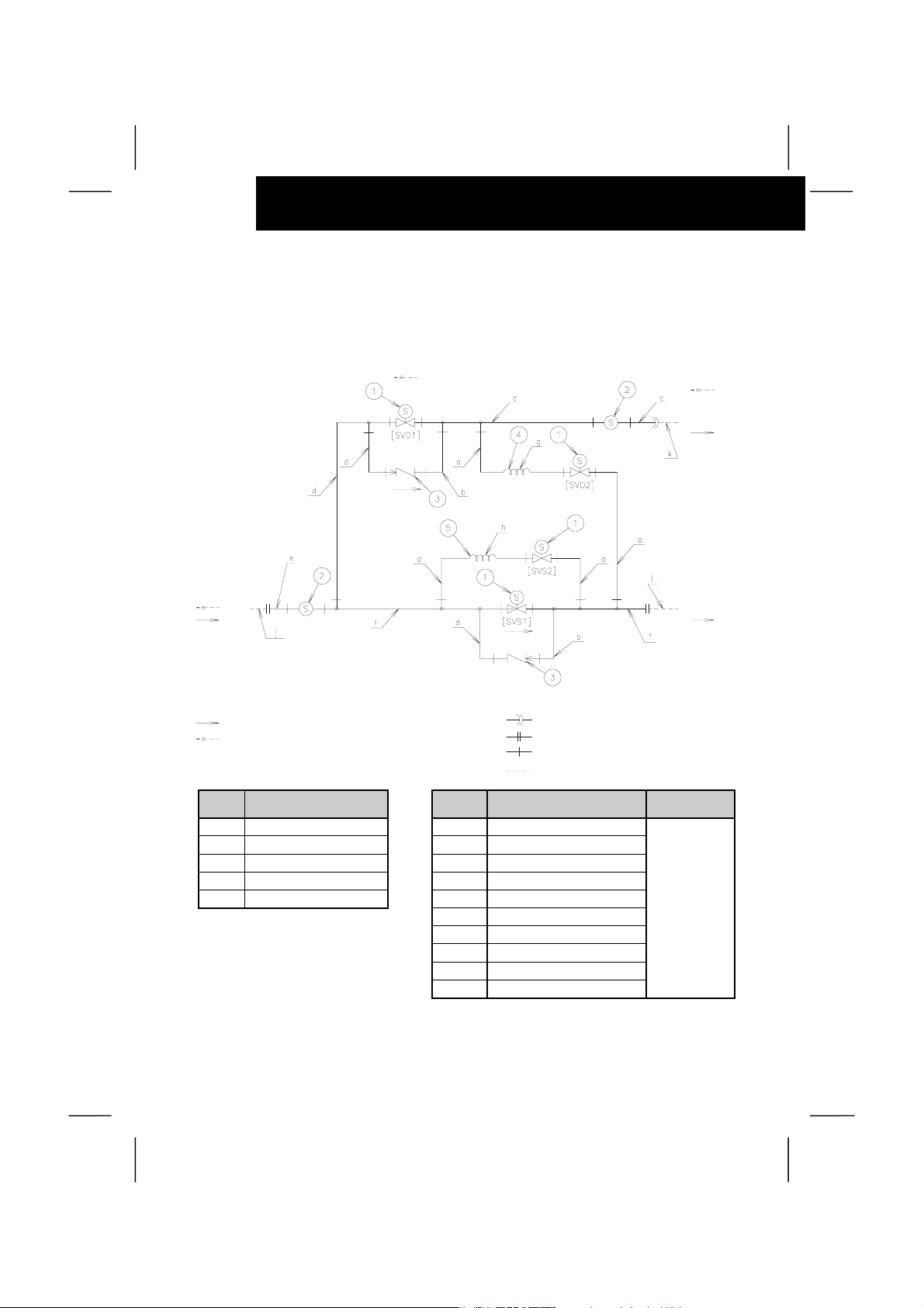
2.2.2. CH Unit – CH-12.0N
To Indoor Unit To Outdoor Unit
Õ
High
Pressure
Gas Line
Ö
High Pressure
Gas Line
Low
Pressure
Gas Line
Low
Pressure
Gas Line
Refrigerant Flow Direction (Cooling Operation) Flare Connection
Refrigerant Flow Direction (Heating Operation) Flange Connection
No Description Mark
1 Solenoid Valve (AC) a
2 Strainer b
3 Check Valve c
4 Capillary Tube d
5 Capillary Tube e
f
g
h
j
k
NOTE:
The mark of inside "[ ]" is shown in the electrical wiring diagram.
Brazing Connection
Field Refrigerant Piping
Material Size
O.D.(mm) × thickness (mm)
∅6.35 x 1.07
∅12.7 x 1.0
∅15.88 x 1.0
∅15.88 x 1.2
∅19.05 x 1.2
∅19.05 x 1.65
∅3.0 x 0.8
∅4.0 x 0.5
∅22.2
∅19.05
Low
Pressure
Gas Line
Material
Copper Tube
C1220T-O
Page 11
TRANSPORTATION AND HANDLING
2.3. NECESSARY TOOLS AND INSTRUMENT LIST FOR INSTALLATION
No. Tool No. Tool
1 Handsaw 11 Spanner
2 Phillips Screwdriver 12 Charging Cylinder
3 Vacuum Pump 13 Gauge Manifold
4 Refrigerant Gas Hose 14 Cutter for Wires
5 Megohmmeter 15 Gas Leak Detector
6 Copper Pipe Bender 16 Leveler
7 Manual Water Pump 17 Clamper for Solderless Terminals
8 Pipe Cutter 18 Hoist (for Indoor Unit)
9 Brazing Kit 19 Ammeter
10 Hexagon Wrench 20 Voltage Meter
3. TRANSPORTATION AND HANDLING
Transport the product as close to the installation location as practical before unpacking
5
ENGLISH
Ô WARNING:
Do not put any foreign material into the CH Unit and check to ensure that none exists in the
outdoor unit before the installation and test run. Otherwise, a fire or failure, etc. may occur.
Ó CAUTION:
Do not put any material on the product.
Be careful not to damage on insulation materials of unit’s surface when lifting.
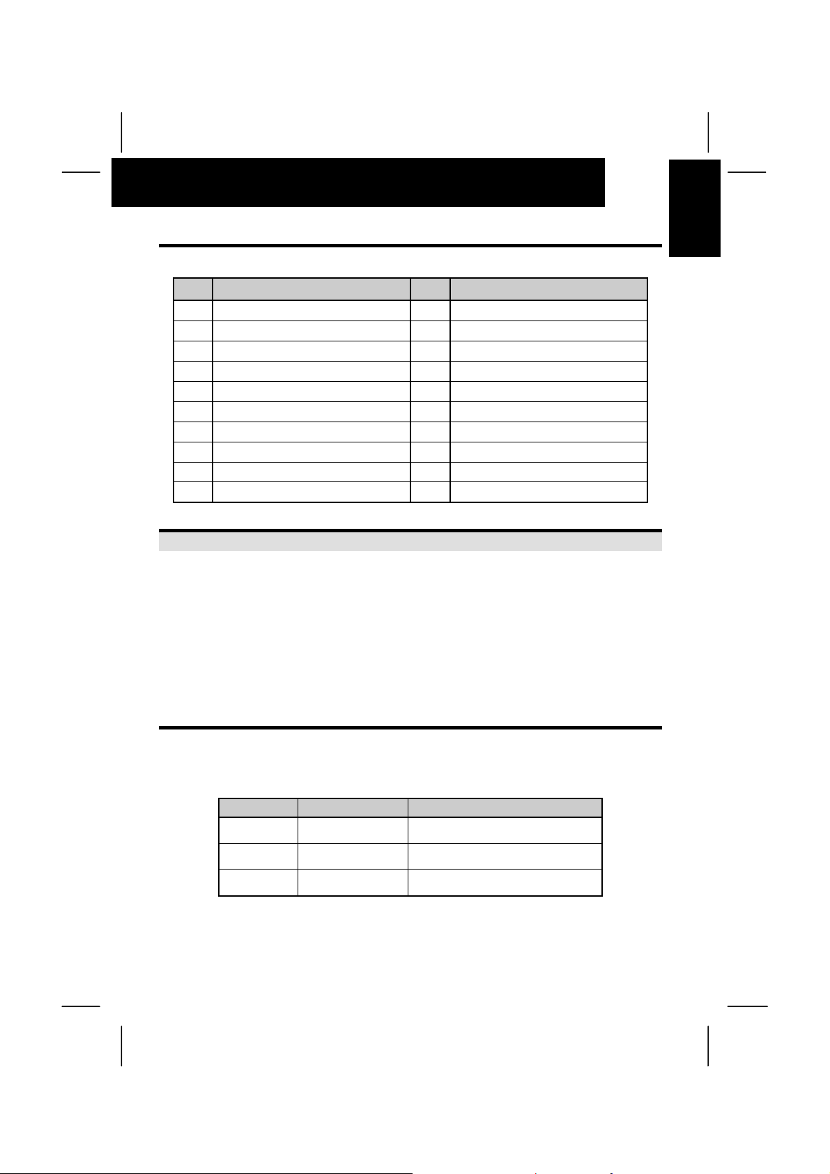
3.1. COMBINATION CH UNIT AND INDOOR UNIT
The CH Unit is Installed indoors for the SET-FREE FXN(E) system, between the outdoor unit and
Indoor unit. The combination of the CH Unit and indoor Unit is as follows.
Model Indoor Unit Quantity Total Indoor Capacity (HP)
CH-4.0NE 1 to 5
CH-8.0NE 1 to 8
CH-12.0N 1 to 5
Smaller than 4.0
(excluding 4.0)
4.0~8.0 (including 4.0
and excluding 8.0)
8.0~12.0 (including 8.0
and including 12.0)
Page 12

6
CH UNIT INSTALLATION
4. CH UNIT INSTALLATION
Õ DANGER:
Do not install the Indoor Unit in a flammable environment to avoid fire or an explosion.
Ô WARNING:
Check to ensure that the ceiling slab is strong enough.
Do not install the CH Unit outside. If installed outdoors, an electric hazard electric leakage will
occur.
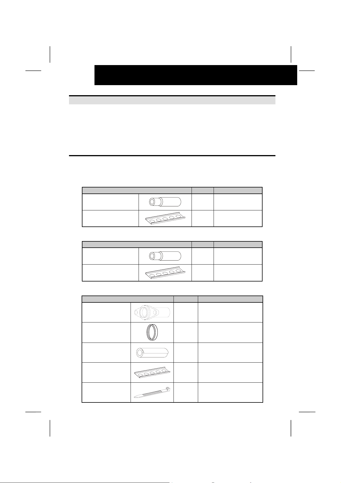
4.1. FACTORY-SUPPLIED ACCESSORIES
Check to ensure that the following accessories are packed with the CH Unit.
Factory Supplied Accessories - For CH-4.0NE.
Accessory Q´ty Purpose
To Connect ∅12.7 liquid
Reducer (∅15.88 to ∅12.7)
Pipe Fixing Band 2 To Fix Liquid Pipe
Factory Supplied Accessories - For CH-8.0NE.
Accessory Q´ty Purpose
Reducer (∅19.05 to ∅15.88)
1
piping of Indoor Unit
To Connect ∅15.88
1
liquid piping of Indoor
Unit
Pipe Fixing Band 2 To Fix Liquid Pipe
Factory Supplied Accessories - For CH-12.0N.
Accessory Q´ty Purpose
Flange Piping Size (∅22.2)
Packing for Flange 2 Flange sealing
Insulation (∅38 ID)
Pipe Fixing Band 2 To Fix Liquid Pipe
Band 8
2
1
For Gas (High) Piping
from Outdoor Unit
For Refrigerant Piping
Connection
To fix Insulation for
Refrigerant Piping
Page 13

CH UNIT INSTALLATION
7
4.2. INITIAL CHECK
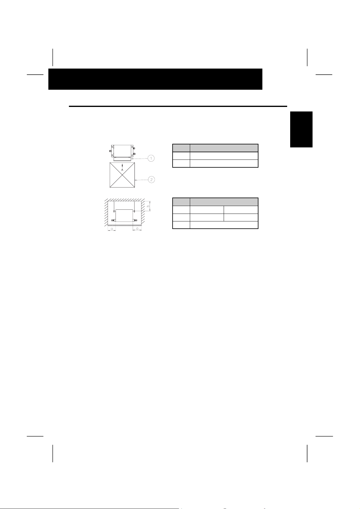
4.2.1. Install the CH unit with a proper clearance around it for maintenance working space, as
shown in below figure:
Service Space
No Description
Electrical Box
o
Service Access Panel
p
View from A
Mark Dimension (Min).
Model CH-4-0/8.0 CH-12.0
a 250mm 350mm
b 100mm
4.2.2. Flowing sound of refrigerant may be heard from the CH unit when the solenoid valve in
the CH unit is activated. Therefore, take the following action to minimize the sound.
- Install the CH unit inside the ceiling. As for the ceiling material, select a material like a plaster
board which minimizes operation sound.
- Do not install the CH unit in near a bed room or hospital room.
- Do not install the CH unit in a hot or humid place like kitchen to prevent dew condensation on the
outer surface of the CH unit.
ENGLISH
4.2.3. Pay attention to the following points when the CH is installed in a hospital or other
facilities where there are electronic waves from medical equipment.
- Do not install the CH unit where the electromagnetic wave is directly radiated to the electrical box
or intermediate wiring (operating line).
- Install the CH unit and components as far as practical or at least 3 meters from the
electromagnetic wave radiator.
- Install a noise filter when the power supply emits harmful noises.
Page 14
8
CH UNIT INSTALLATION
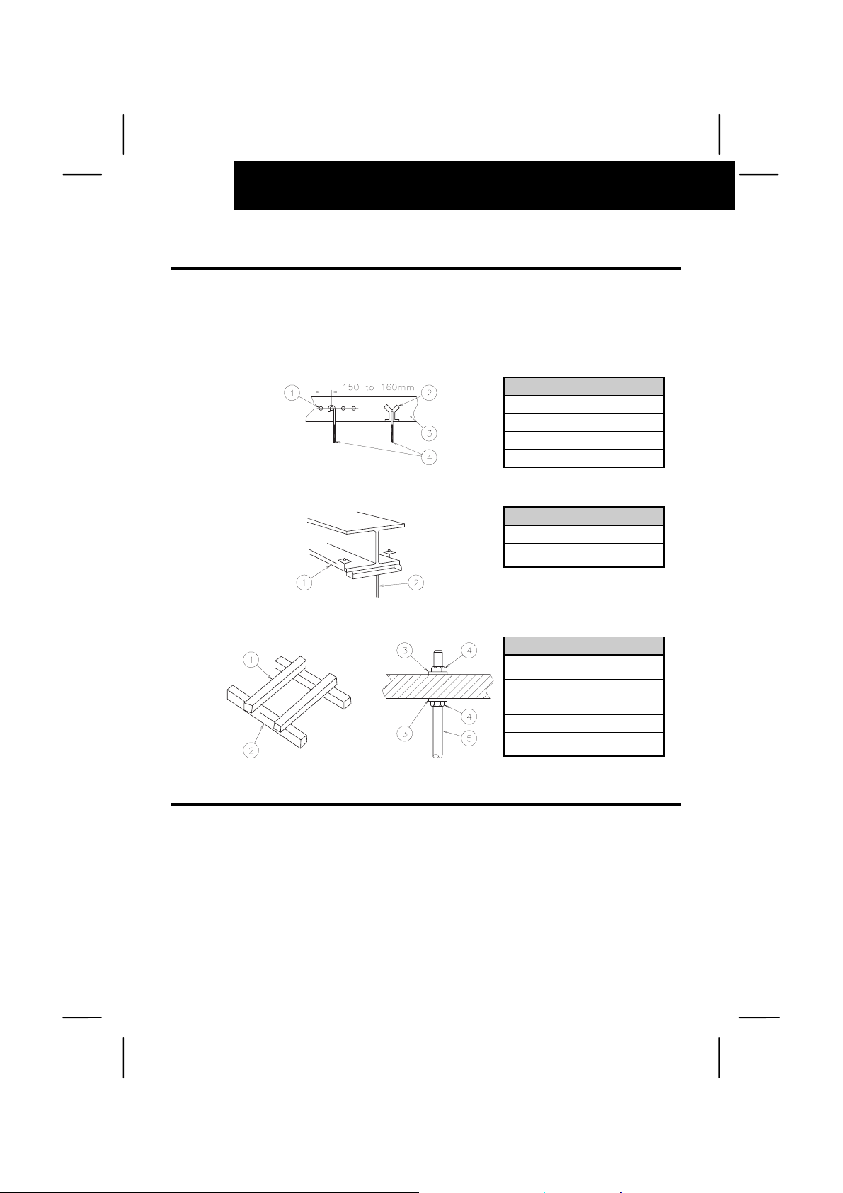
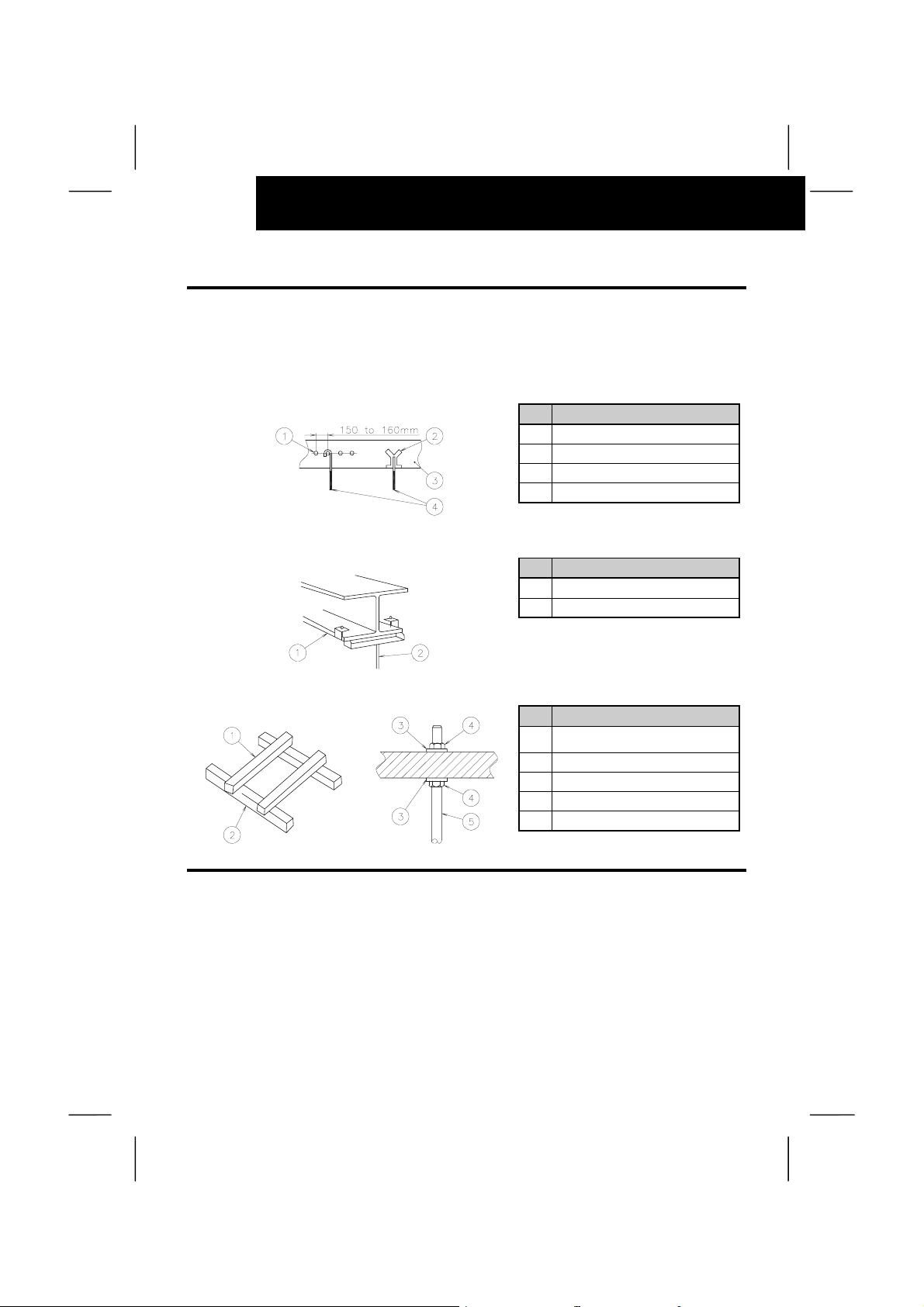
4.3. SUSPENSION BOLTS
- Select final location and installation direction of the indoor unit paying careful attention to the
space for the piping, wiring and maintenance.
- Mount suspension bolts, as shown below:
- For Concrete Slab:
No Description
Steel
o
Insert (100 to 150kg)
p
Concrete
q
Anchor Bolt (W3/8 or M10)
r
- For Steel Beam:
No Description
I Beam
o
Suspension Bolt
p
(W3/8 or M10)
- For Wooden Beam Suspension:
No Description
Wooden Bar
o
(60~90mm Square)
Wooden Beam
p
Square Washers
q
Nuts
r
Suspension Bolts
s
(W3/8 or M10)
4.4. INSTALLATION
4.4.1. Marking Position of the Suspension Bolts and Piping Connections
- Mark position of the Suspension bolts, refrigerant piping connections and drain connection.
- See Installation dimensions in chapter 2.1.
Page 15
CH UNIT INSTALLATION
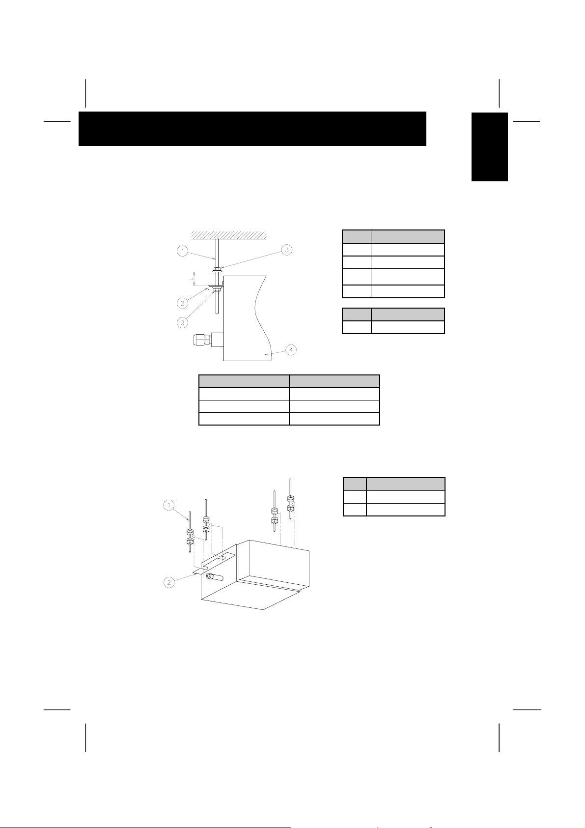
4.4.2. Mounting the CH Unit
How to put Nuts
Put nuts on each of the four suspension bolts before suspending the CH unit, as shown below
No Description
Suspension Bolt
o
Suspension Bracket
p
Nut & Washer
q
(Field-Supplied)
CH-Box
r
Mark Dimension
L 30~50mm
Field-Supplied Parts CH-(4.0/8.0/12.0)N(E)
Suspension Bolts 4-M10 or W-3/8
Nut 8-M10 or W-3/8
Washer 8-M10 or W-3/8
9
ENGLISH
Suspension the CH Unit
Hook suspension bracket to the nut and washer of each suspension bolt, as shown below.
Check that the nuts and washers are correctly fixed by the retainers of the suspension bracket.
No Description
Suspension Bolt
o
Suspension Bracket
p
Page 16
10
REFRIGERANT PIPING WORK
4.4.3. Adjusting of the Unit Level
How to put Nuts
In order to avoid an incorrect unit operation, check the level of the unit using a water level in a
transparent Vinyl tube containing water.
No Description
Vinyl Tube
o
Level Scale
p
Tighten the bolts of the suspension nuts with the suspension brackets after adjustment is completed.
Special plastic paint must be applied to the bolts in order to prevent them from loosening.
5. REFRIGERANT PIPING WORK
Õ DANGER:
Use refrigerant R410A in the refrigerant cycle. Do not charge oxygen, acetylene or other
flammable and poisonous gases into the refrigerant cycle when performing a leakage test or
an air-tight test. These types of gases are extremely dangerous and can cause an explosion. It
is recommended that compressed air, nitrogen or refrigerant be used for these types of tests.
5.1. PIPING MATERIALS
1. Prepare locally-supplied copper pipes.
2. Select clean copper pipes. Make sure there is no dust and moisture inside. Before connecting
pipes, blow the inside of the pipes with nitrogen or dry air, to remove any dust or foreign
materials.
3. Select the piping size from dimensional drawing
5.2. PIPING CONNECTION
1. Position of piping connection is shown in dimensional drawing.
2. Connect the accessories as shown in the Diagram bellow:
CH-(4.0/8.0)NE
No Description
Pipe Fixing Band
To
Indoor
Unit
{
Outdoor
}
To
Unit
o
Liquid Pipe
p
Low Gas Pipe
q
High Gas Pipe
r
Gas Pipe
s
Reducer
t
Field-Supplied Piping
Page 17
REFRIGERANT PIPING WORK
}
CH-12.0N
No Description
To
Indoor
Unit
{
3. When tightening the Flare nut, use two spanners as shown in below figure.
Pipe Size Tightening Torque (N.m)
∅6.35
∅9.53
∅12.7
∅15.88
∅19.05
(1/4) 2
(3/8) 4
(1/2) 6
(5/8) 8
(3/4) 10
To
Outdoor
Unit
Pipe Fixing Band
o
Liquid Pipe
p
High Gas Pipe
q
Low Gas Pipe
r
Gas Pipe
s
Pipe Flange
t
Field-Supplied
Piping
11
ENGLISH
4. After connecting the refrigerant piping, seal the refrigerant pipes by using the field-supplied
insulation materials as shown in figure below.
Use the factory-supplied pipe with a flange to connect low-pressure gas piping. The gasket at the
unit gas piping inlet should be replaced to the one supplied with your unit.
(Thermal insulator over the flange connection should be field-supplied).
NOTE:
The factory-supplied flange should be welded with the connection pipe before connecting the
valve. Mount the Insulation’s after the pipe brazing. Take particular care upon connecting
flange so that Insulation is correctly located.
To
Indoor
{}
Unit
No Description Remarks
Insulation - Field Supplied – CH-4.0NE unit
o
Insulation - Field Supplied – CH-(4.0/8.0/12.0)NE units
p
Insulation
q
- Field Supplied – CH-(4.0/8.0)NE
- Included in CH-12.0N unit as accessory.
To
Outdoor
Unit
Page 18
12
ELECTRICAL WIRING
CAUTION:
- Cover the end of the pipe if the pipe has to be inserted through a hole.
- Do not put pipes on the ground directly without a cap or vinyl tape at the end of the pipe.
- Remove all the flammable materials around the units. If not, it will cause a fire.
Correct Incorrect
5. Evacuation and refrigerant charging procedures should be performed according to “Installation
and Operation Manual” of Outdoor unit – Chapter: “Piping and Refrigerant Charge”.
6. ELECTRICAL WIRING
ÔWARNING:
- Turn OFF the main power switch to the CH unit, the indoor unit and the outdoor unit before
electrical wiring work or a periodical check is performed.
- Protect the wires, electrical parts, etc. from rats or other vermin.
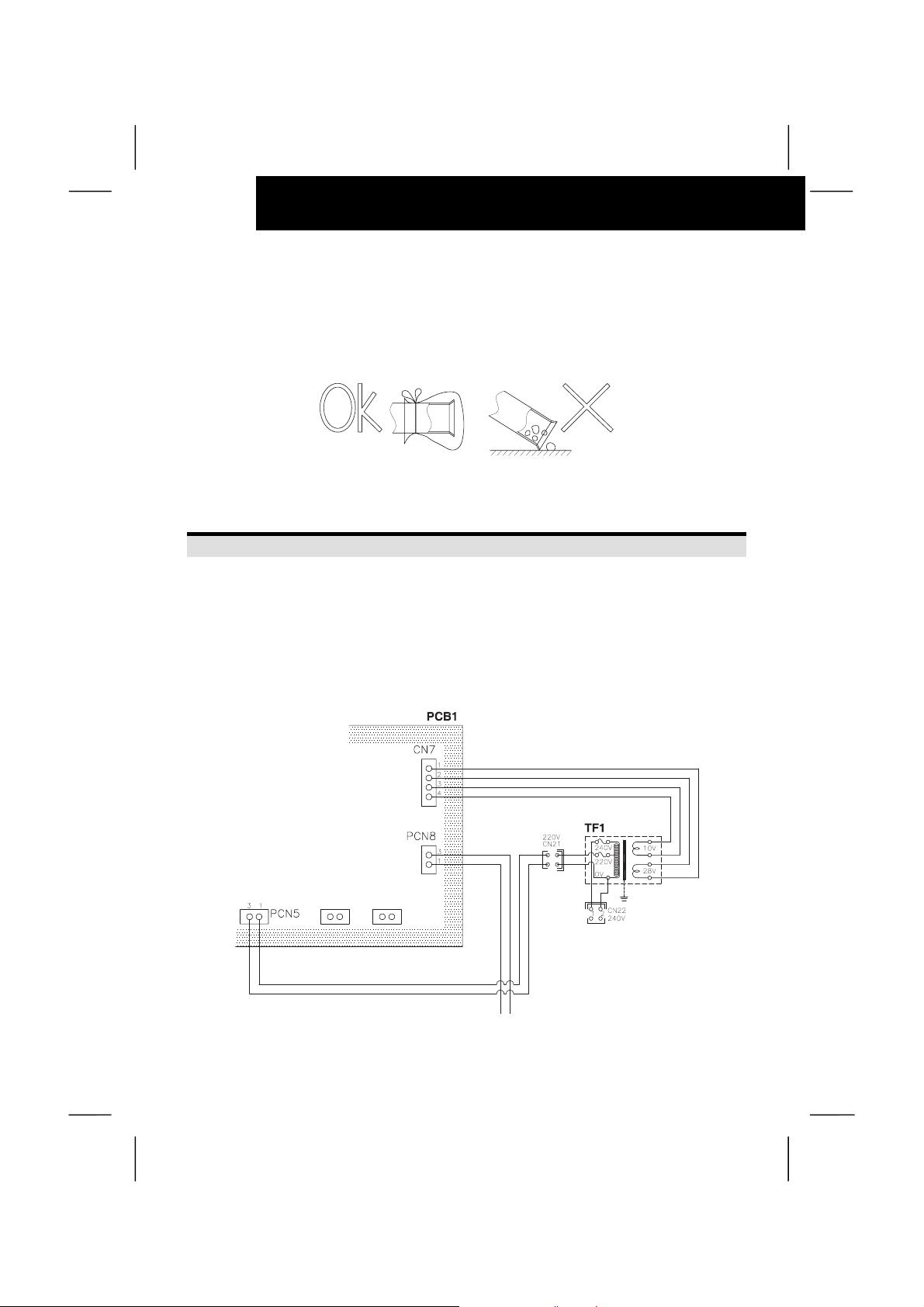
- Check the item below before turning ON the main switch.
In case that the power source for indoor unit 240V (nominal voltage), change CN21 (connector)
to CN22 of transformer (TF1) in the electrical control box as shown below.
CAUTION:
- Wrap the accessory packing around the wires, and plug the wiring connection hole with the
seal material to protect the product from any condensate water or insects.
- Tightly secure the wires with the cord clamp inside the electrical box.
Page 19
ELECTRICAL WIRING
13
6.1. GENERAL CHECK
- Make sure that the field-selected electrical components (main power switches, circuit breakers,
wires, conduit connectors and wire terminals) have been properly selected according to the
electrical data indicated in Technical Catalogue. Make sure that the components comply with
National Electrical code (NEC)
- Check to ensure that the power supply voltage is within ±10% of rated voltage.
- Check the power source capacity is too low, the system cannot be started due to the voltage drop.
- Check to ensure that the ground wire is connected.
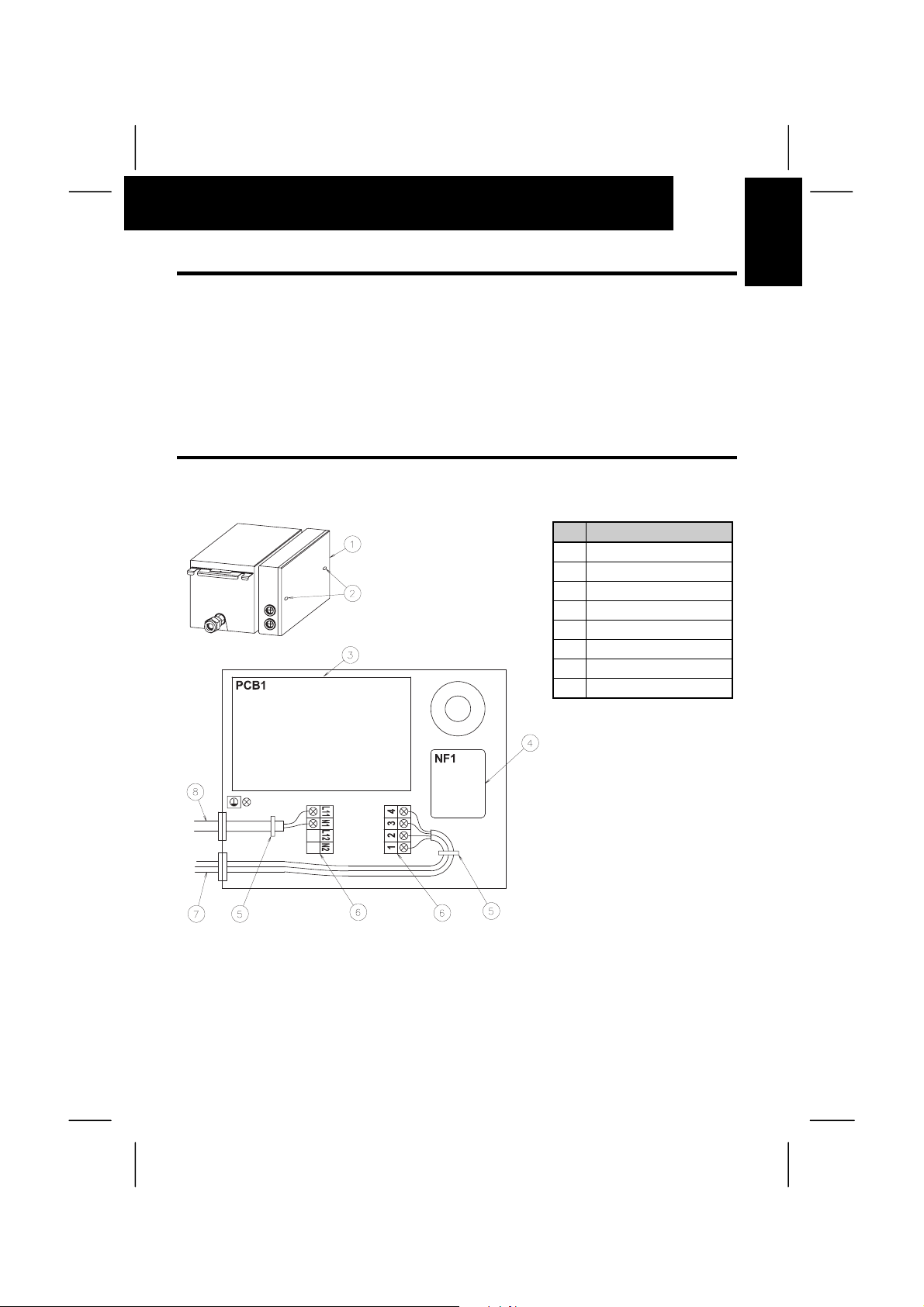
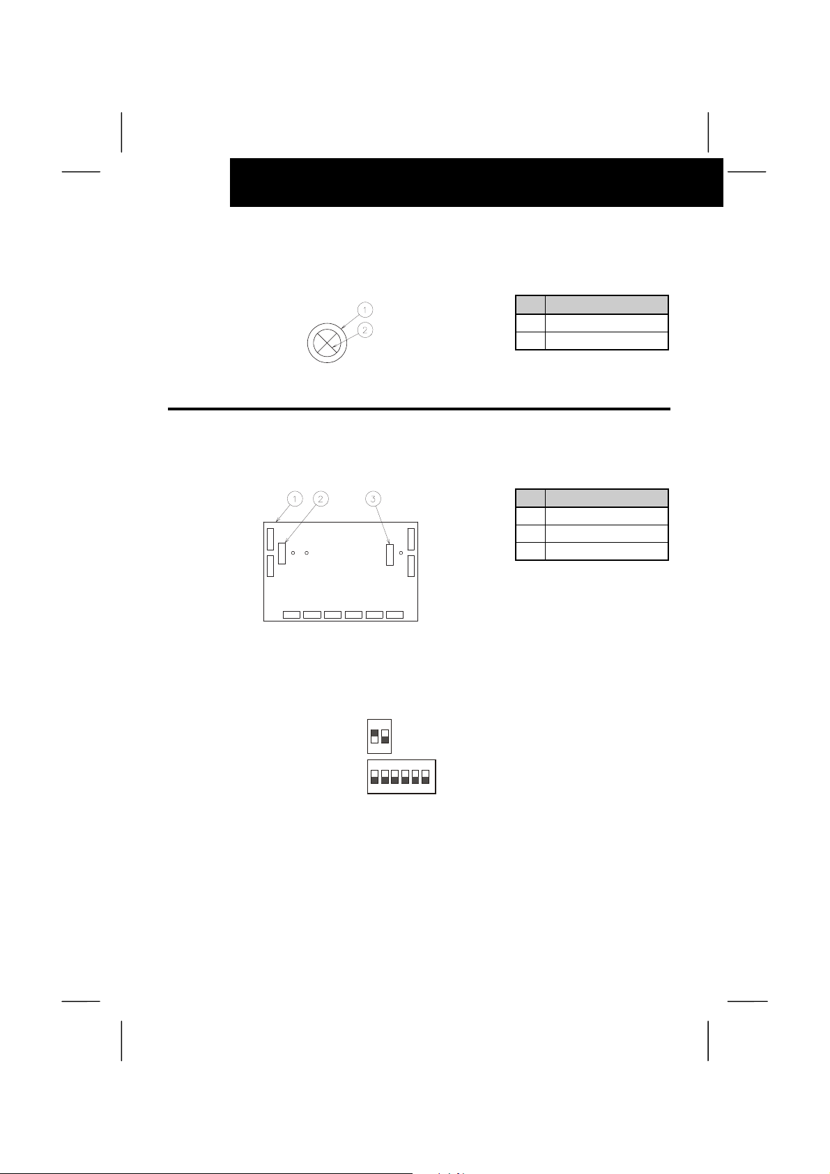
6.2. ELECTRICAL WIRING CONNECTION
The electrical wiring connection is shown in below figure.
No Description
Electrical Box Cover
o
Fixing Screw
p
Printed circuit Board
q
Noise Filter
r
Cord Clamp
s
Terminal Board
t
Operating Line
u
Power Supply Line
v
ENGLISH
NOTE:
At the terminal board 2, the
connectors 1 and 2 are for
H Link system, and the
connectors 3 and 4 are for
going to the Indoor Unit
from the CH-Box setting of
dip switches
1. Turn OFF the main power switch and take off the electrical box cover of CH unit.
2. Cut out the center of the rubber bushing in the wiring connection hole, as shown below.
3. Connect the power supply and earth wires to the terminals in the electrical box.
4. Connect the wires of the operating line to the terminals in the electrical box.
Page 20
14
ELECTRICAL WIRING
5. Tightly clamp the wires using the cord clamp inside the electrical box.
6. Fix the electrical box cover after wiring work.
No Description
Rubber Bushing
o
Cut Inside
p
6.3. SETTING OF DIP SWITCHES
Position of Dip Switches
The PCB1 in the electrical box of CH unit is equipped with 2 types of dip switches (DSW2, DSW5),
as shown in the figure below.
No Description
PCB1
o
DSW5
p
DSW2
q
Setting of Dip Switches
The dip switches are set before shipment and no setting in the field is required. These are utilized for
the self-diagnosis of PCB.
Factory Setting Position (Dip Switch)
¥ DSW5
¥ DSW2
NOTE:
The "" mark indicates position of dip switches. The above figures show the setting before
shipment.
ON
1 2
ON
1 2 3 4 5 6
CAUTION:
Before setting dip switches, firstly turn OFF power source and set the position of the dip
switches. If the switches are set without turning OFF the power source, the switch can not
function.
Page 21
TEST RUN
7. TEST RUN
Test run should be performed according to “Installation & Operation Manual” of Outdoor unit.
Ô WARNING:
Do not operate the system until all the check points have been cleared.
- Check to ensure that the electrical resistance is more than 1 M
resistance between ground and the terminal of the electrical parts. If not, do not operate the
system until the electrical leakage is found and repaired.
- Check to ensure that the stop valves of the outdoor unit are fully opened, and then start the
system.
- Check to ensure that the switch on the main power source has been ON for more than 12
hours, to warm the compressor oil by the crankcase heater.
Pay attention to the following items while the system is running.
- Do not touch any of the parts by hand at the discharge gas side, since the compressor
chamber and the pipes at the discharge side are heated higher than 90Cº.
- DO NOT PUSH THE BUTTON OF THE MAGNETIC SWITCH(ES). It will cause a serious
accident.
Ω
, by measuring the
15
ENGLISH
Page 22

Page 23
RESUMEN DE SEGURIDAD 17
1. RESUMEN DE SEGURIDAD
Ô ADVERTENCIA:
- Al realizar la instalación y conectar la tubería de refrigerante y el cableado eléctrico, siga las
instrucciones de nuestro manual de instalación.
- Compruebe que la toma de tierra está bien conectada.
- Conecte un fusible de la capacidad especificada.
PRECAUCIÓN:
- Cuando instale la unidad CH y el cable, procure que la distancia mínima hasta la fuente más
próxima de ondas electromagnéticas, como los equipos médicos, sea de 3 metros
aproximadamente.
2. ESTRUCTURA
2.1. DIMENSIONES
2.1.1. Modelo: Unidad CH-(4.0/8.0)NE
ESPAÑOL
Unidad:mm
Hacia la maquina Interior Hacia la maquina Exterior
Nº Descripción
1 Soporte de Suspensión Para pernos M8 o W5/16
2 Conexión tubería gas refrigerante (Baja)
3 Conexión tubería gas refrigerante (Alta)
4 Conexión del tubo de gas refrigerante
5 Accesorios (Disponible sujetarla en ambos lados)
6 Orificio para la línea de servicio
7 Orificio para la línea de alimentación
Dimensiones a 78mm 82mm
15.88 Conexión abocardada 19.05 Conexión abocardada
15.88 Conexión abocardada 19.05 Conexión abocardada
CH-4.0NE CH-8.0NE
12.7 Conexión abocardada 15.88 Conexión abocardada
Observaciones
26.5
26.5
Page 24
18 ESTRUCTUR
A
2.1.2. Modelo: Unidad CH-12.0N
Hacia la maquina Interior Hacia la maquina Exterior
Unidad:mm
Nº Descripción
1 Soporte de Suspensión Para pernos M8 o W5/16
2 Conexión tubería gas refrigerante (Baja)
3 Conexión tubería gas refrigerante (Alta)
4 Conexión del tubo de gas refrigerante
5 Accesorios (Disponible sujetarla en ambos lados)
6 Orificio para la línea de servicio
7 Orificio para la línea de alimentación
Observaciones
CH-12.0N
∅22.2 Conexión con brida
∅19.05 Conexión abocardada
∅22.2 Conexión con brida
∅26.5
∅26.5
Page 25
2.2. CICLO FRIGORÍFICO
2.2.1. Unidad (CH-4.0/8.0NE)
Hacia unidad
interior
Õ
Alta
presión
Tubería
de Gas
ESTRUCTURA 19
Hacia unidad
exterior
Ö
Alta
presión
Tubería
de Gas
Baja
presión
Tubería
de Gas
ESPAÑOL
Baja
presión
Tubería
de Gas
Dirección del Flujo de refrigerante (modo enfriamiento)
Dirección del Flujo de refrigerante (modo calefacción)
Nº Descripción Marca
1 Válvula Solenoide (AC) a
2 Filtro b
3 Válvula de Comprobación c
4 Tubo Capilar d
5 Tubo Capilar e
f
g
h
j
k
O.D.(mm) × grosor (mm)
CH-4.0NE CH-8.0NE
∅12.7×1.0 ∅15.88×1.0
∅9.53×0.8 ∅12.7×1.0
∅4.0x0.8 ∅4.0x0.5
∅12.7×1.0 ∅15.88×1.2
∅15.88 ∅19.05
Conexión abocardada
Conexión soldada
Tuberías de refrigerante
Dimensión Material
∅2.5x0.7
∅6.35×1.07
∅9.53×0.8
∅12.7×1.0
∅12.7 ∅15.88
NOTA:
La inscripción entre corchetes "[ ]" aparece en el diagrama del cableado eléctrico.
Baja
presión
Tubería
de Gas
Material
Tubo de Cobre
C1220T-O
Page 26
20 ESTRUCTUR
A
2.2.2. Unidad CH-12.0N
Hacia maquina
interior
Õ
Alta
presión
Tubería
de Gas
Hacia maquina
exterior
Ö
Alta
presión
Tubería
de Gas
Baja
presión
Tubería
de Gas
Baja
presión
Tubería
de Gas
Dirección del Flujo de refrigerante (modo enfriamiento) Conexión abocardada
Dirección del Flujo de refrigerante (modo calefacción) Conexión con brida
Conexión soldada
Tuberías de refrigerante
Nº Descripción Marca
1 Válvula solenoide (AC) a
2 Filtro b
3 Válvula de Comprobación c
4 Tubo Capilar d
5 Tubo Capilar e
f
g
h
j
k
Dimensión Material
O.D.(mm) × grosor (mm)
∅6.35 x 1.07
∅12.7 x 1.0
∅15.88 x 1.0
∅15.88 x 1.2
∅19.05 x 1.2
∅19.05 x 1.65
∅3.0 x 0.8
∅4.0 x 0.5
∅22.2
∅19.05
NOTA:
La inscripción entre corchetes "[ ]" aparece en el diagrama del cableado eléctrico.
Baja
presión
Tubería
de Gas
Material
Tubo de Cobre
C1220T-O
Page 27
TRANSPORTE Y MANEJO 21
2.3. LISTA DE HERRAMIENTAS E INSTRUMENTAL NECESARIOS PARA LA INSTALACIÓN
Nº Herramienta Nº Herramienta
1 Sierra de mano 11 Llave inglesa
2 Destornillador Phillips 12 Cilindro de carga
3 Bomba de vacío 13 Colector del manómetro
4 Manguera gas refrigerante 14 Corta cables
5 Megaohmímetro 15 Detector de escapes de gas
6 Curvador para tubos de cobre 16 Nivel
7 Bomba de agua manual 17
8 Corta tubos 18 Cabria (para izar la unidad interior)
9 Equipo de soldadura 19 Amperímetro
10 Llave allen 20 Medidor de voltaje
Grapa para terminales de fijación sin
soldadura
3. TRANSPORTE Y MANEJO
Antes de desempaquetar el producto, transpórtelo lo más cerca posible del lugar de instalación.
Ô ADVERTENCIA:
No introduzca ningún objeto extraño dentro de la unidad CH y compruebe que no se ha
introducido ninguno en la unidad interior antes de llevar a cabo la instalación y la prueba de
funcionamiento. De lo contrario, puede provocarse un incendio o una avería.
ESPAÑOL
Ó PRECAUCIÓN:
No coloque ningún tipo de material sobre el producto.
Al izar la unidad, tenga precaución para no dañar los materiales aislantes de la superficie.
3.1. COMBINACIÓN DE LA UNIDAD CH Y LA UNIDAD INTERIOR
La unidad CH se instala en el interior para dar soporte al sistema SET-FREE FXN(E), entre la
unidad exterior y la interior. La combinación de la unidad CH y la interior es como sigue:
Modelo
CH-4.0NE 1 a 5
CH-8.0NE 1 a 8
CH-12.0N 1 a 5
Nº unidades
interiores
Capacidad total interior (HP)
Inferior a 4.0
(sin incluir 4.0)
4.0 ~ 6.5 (incluyendo 4.0
y excluyendo 8.0)
8.0 ~ 12.0 (incluyendo 8.0
e incluyendo 12.0)
Page 28
22 INSTALACIÓN DE LA UNIDAD CH
4. INSTALACIÓN DE LA UNIDAD CH
Õ PELIGRO:
No instale la unidad interior en lugares inflamables para evitar incendios y explosiones.
Ô ADVERTENCIA:
Compruebe que las placas del techo son suficientemente resistentes.
No instale la unidad CH en el exterior. Si lo hace, hay riesgo de dispersión eléctrica.
4.1. PARA FIJAR EL AISLANTE DEL TUBO REFRIGERANTE SUMINISTRADOS DE FÁBRICA
Compruebe que el paquete de la unidad CH incluye los siguientes Para fijar el aislante del tubo
refrigerante:
Para fijar el aislante del tubo refrigerante suministrados de fábrica (para CH-4.0NE)
Accesorios Cantidad Propósito
Para conectar el tubo de
Reductor (∅15.88 a ∅12.7)
Brida fijadora de tubo 2
Para fijar el aislante del tubo refrigerante suministrados de fábrica (para CH-8.0NE)
Accesorios Cantidad Propósito
Reductor (∅19.05 a ∅15.88)
Brida fijadora de tubo 2
1
liquido ∅12.7 de la
unidad interior
Para fijar el tubo de
liquido
Para conectar el tubo de
1
liquido ∅15.88 de la
unidad interior
Para fijar el tubo de
liquido
Para fijar el aislante del tubo refrigerante suministrados de fábrica (para CH-12.0N)
Accesorios Cantidad Propósito
Tubo con brida.
Tamaño: (∅22.2)
Obturador para brida 2 Sellado con brida
Aislante (∅38 ID)
Brida fijadora de tubo 2 Para fijar el tubo de liquido
Brida Flexible 8
Para conectar el tubo de gas
2
(alto) procedente de la unidad
exterior
Para conectar los tubos de
1
refrigerante
Para fijar el aislante del tubo
refrigerante
Page 29
INSTALACIÓN DE LA UNIDAD CH 23
4.2. COMPROBACIONES INICIALES
4.2.1. Cuando instale la unidad CH, procure que haya suficiente espacio a su alrededor para
trabajar, tal como se indica en la figura:
Panel de Acceso
Nº Descripción
Caja eléctrica
o
Panel de Acceso
p
Vista desde A
Marca Dimensiones (Min)
Modelo CH-4.0/8.0 CH-12.0
a 250mm 350mm
b 100mm
4.2.2. Al activar la válvula solenoide de la unidad CH es posible que se escuche el ruido que
produce el refrigerante. Para reducir al mínimo este ruido, tome las siguientes medidas:
- Instale la unidad CH empotrada en el techo. Como material para el techo, escoja uno del tipo de
las placas de escayola, que reduce al mínimo el ruido del aparato en funcionamiento.
- No instale la unidad CH cerca de un dormitorio o en una sala de hospital.
- No instale la unidad CH en ningún lugar húmedo, como una cocina, para evitar que se condense
rocío en la superficie exterior de la unidad CH.
ESPAÑOL
4.2.3. Si ha de instalar la unidad CH en un hospital u otro tipo de local donde haya ondas
eléctricas generadas por equipos médicos, preste atención a los siguientes puntos:
- No instale la unidad CH en lugares donde la Accesorios o los cables intermedios reciban
directamente la radiación electromagnética.
- Instale la unidad CH y los componentes tan lejos como sea posible de la fuente de radiaciones
electromagnéticas o, como mínimo, a 3 metros de distancia.
- Instale un filtro antirruido cuando la fuente de alimentación emita ruidos molestos.
Page 30
24 INSTALACIÓN DE LA UNIDAD CH
4.3. PERNOS DE SUSPENSIÓN
- Escoja el lugar definitivo y la dirección en que desea instalar la unidad interior, con especial
atención al espacio destinado a los tubos, el cableado y el mantenimiento.
- Monte los pernos de suspensión, tal como indica la figura.
- Para placas de hormigón:
Nº Descripción
Acero
o
Insertar (100 a 150kg)
p
Hormigón
q
Perno de anclaje (W3/8 a M10)
r
- Para vigas de acero
Nº Descripción
Viga en doble T
o
Perno de suspensión (W3/8 a M10)
p
- Para suspensión en viguetas de madera:
Nº Descripción
Barra de madera (60~90mm
o
Cuadrada)
Vigueta de madera
p
Arandelas cuadradas
q
Tuercas
r
Perno de suspensión (W3/8 a M10)
s
4.4. INSTALACIÓN
4.4.1. Señalización de los puntos para los pernos de suspensión y las conexiones de los
tubos
- Marque los puntos exactos de los pernos de suspensión, las conexiones de los tubos de
refrigerante y de desagüe
- Ver las Dimensiones de Instalación en el apartado 2.1.
Page 31

INSTALACIÓN DE LA UNIDAD CH 25
4.4.2. Montaje de la unidad CH
Cómo colocar las tuercas
Coloque las tuercas en cada uno de los cuatro pernos de suspensión antes de suspender la
unidad CH, tal como muestra la figura.
Nº Descripción
Perno de suspensión
o
Soporte de Suspensión
p
Tuerca & Arandela
q
(Suministrado Instalador)
CH-Box
r
Marca Dimensiones
L 30~50mm
ESPAÑOL
Piezas no incluidas de
fabrica
Perno de suspensión 4-M10 a W-3/8
Tuerca 8-M10 a W-3/8
Arandela 8-M10 a W-3/8
CH-(4.0/8.0/12.0)N(E)
Suspensión de la unidad CH
Cuelgue los soportes de suspensión del juego de tuerca y arandela de cada uno de los pernos de
suspensión, como muestra la figura.
Compruebe que las tuercas y las arandelas están bien sujetas por los retenes de los soportes de
suspensión.
Nº Descripción
Perno de suspensión
o
Soporte de Suspensión
p
Page 32

26 INSTALACIÓN DE LOS TUBOS DE REFRIGERANTE
{
4.4.3. Ajuste del nivel de la unidad
Cómo colocar las tuercas
Para evitar el mal funcionamiento de la unidad, compruebe el nivel de la maquina con un medidor de
nivel, un tubo de vinilo transparente con agua dentro.
Nº Descripción
Tubo de vinilo
o
Escala de nivel
p
Una vez realizado el ajuste, apriete los pernos de las tuercas de suspensión a sus soportes.
Aplíquese pintura plástica especial a los pernos con el fin de evitar que se aflojen.
5. INSTALACIÓN DE LOS TUBOS DE REFRIGERANTE
Õ PELIGRO:
Para el circuito de refrigerante, utilice R410A. No cargue oxígeno, acetileno ni ningún otro gas
inflamable ni venenoso en el circuito cuando compruebe si hay fugas o haga pruebas de
estanqueidad. Estos tipos de gases son extremadamente peligrosos y pueden provocar una
explosión. Recomendamos utilizar aire comprimido, nitrógeno o refrigerante para realizar este
tipo de pruebas.
5.1. MATERIALES DE LAS TUBERÍAS
1. Prepare tubos de cobre (no suministrados).
2. Seleccione tuberías de cobre limpias. Asegúrese de que no haya polvo ni humedad en su
interior. Antes de conectar los tubos, insufle nitrógeno o aire seco al interior de los tubos para
eliminar cualquier resto de polvo o sustancias extrañas.
3. Seleccione el tamaño de tubo en el dibujo acotado.
5.2. CONEXIÓN DE LA TUBERÍA
1. En el dibujo acotado podrá ver la posición de las conexiones de los tubos.
2. Conecte los filtros Para fijar el aislante del tubo refrigerante y los manguitos reductores, tal como
indica la siguiente figura.
CH-(4.0/8.0)NE
No Descripción
Brida fijadora de tubo
o
Tubo de liquido
Hacia
unidad
interior
}
Hacia
unidad
exterior
p
Tubo de Gas Bajo
q
Tubo de Gas Alto
r
Tubo de Gas
s
Reductor
t
Tubo suministrado
por el instalador
Page 33

INSTALACIÓN DE LOS TUBOS DE REFRIGERANTE 27
CH-12.0N
No Descripción
Brida fijadora de tubo
o
Tubo de Liquido
p
Tubo de Gas Alto
Hacia
unidad
interior
{
3. Apriete la tuerca abocardada con dos llaves inglesas, tal como indica la figura.
Tamaño de tubería Par de Apriete (N.m)
∅6.35
∅9.53
∅12.7
∅15.88
∅19.05
4. Una vez conectados los tubos de refrigerante, séllelos con el material aislante que lo suministra
el instalador, tal como muestra la siguiente figura.
Para conectar el gas a baja presión, utilice el tubo con brida que es suministrado por fábrica.
Retire la junta obturadora de la entrada del tubo de gas de la unidad por otra, que se suministra
con el equipo.
(El aislante térmico que recubre la conexión embridada no se suministra de fábrica; deberá
adquirirlo en un establecimiento).
Hacia
unidad
exterior
}
(1/4) 2
(3/8) 4
(1/2) 6
(5/8) 8
(3/4) 10
q
Tubo de Gas Bajo
r
Tubo de Gas
s
Tubo con brida
t
Tubo suministrado
por el instalador
ESPAÑOL
NOTA:
La brida que se suministra de fábrica debe soldarse al tubo de conexión antes de conectar la
válvula. Tras soldar el tubo, monte la junta de obturación. Preste especial atención a la
conexión embridada; asegúrese de que la junta obturadora queda correctamente colocada.
Hacia
unidad
interior
Nº Descripción Observaciones
o
p
q
{ }
Aislante - Suministrado por el instalador – CH-4.0NE
Aislante - Suministrado por el instalador – CH-(4.0/8.0/12.0)NE
Aislante
- Suministrado por el instalador – CH-(4.0/8.0)NE
- Incluido en la unidad CH-12.0N como accessorio.
unidad
exterior
Hacia
Page 34

28 CABLEADO ELÉCTRICO
PRECAUCIÓN:
- Si tiene que introducir el tubo por un agujero, ponga un tapón en el extremo.
- No coloque tuberías directamente sobre el suelo sin haber colocado un tapón o cinta de vinilo
en el extremo de la misma.
- Retire todas las sustancias inflamables de las cercanías de las unidades. Pueden provocar
un incendio.
Correcto Incorrecto
5. El vaciado y cambio del refrigerante se debe realizar según las instrucciones del “Manual de
instalación y funcionamiento” de la unidad exterior.
6. CABLEADO ELÉCTRICO
ÔADVERTENCIA:
- Desconecte el interruptor principal de la unidad CH, la unidad interior y la exterior antes de
comenzar a instalar el cableado y cada vez que se lleve a cabo una comprobación periódica.
- Proteja los cables y demás componentes eléctricos de las ratas y demás alimañas.
- Preste atención a la siguiente información antes de conectar el interruptor principal.
En caso de que la fuente de alimentación de la unidad interior, tenga un voltaje nominal de 240
V cambie el conector CN21 al CN22 del transformador TF1 de la caja de control eléctrico, tal
como indica la figura.
ATENCIÓN:
- Proteja los cables con el embalaje accesorio y tape el orificio de conexión con el material de
sellado para así proteger el producto de la condensación de agua y los insectos.
- Sujete con firmeza los cables con la abrazadera dentro de la Accesorios.
Page 35

CABLEADO ELÉCTRICO 29
6.1. COMPROBACIONES GENERALES
- Asegúrese de que todos los componentes eléctricos (interruptores principales, disyuntores,
cables, conectores para las canaletas y terminales para cable) son los adecuados, según los
datos eléctricos que figuran en el catálogo técnico. Compruebe que todos los componentes
cumplen las normas nacionales en materia de electricidad.
- Compruebe que la tensión de la fuente de alimentación está dentro del +/-10% de la tensión
nominal.
- Compruebe la capacidad de la fuente de alimentación; si es demasiado baja, el sistema no podrá
arrancar por la bajada de tensión.
- Asegúrese de que el cable de toma de tierra está conectado.
6.2. CONEXIÓN DEL CABLEADO ELÉCTRICO
En esta figura le indicamos las conexiones del cableado eléctrico.
Nº Descripción
Caja eléctrica
o
Tornillo de fijación
p
Placa de circuitos impresos
q
Filtro de sonido
r
Brida sujeta cables
s
Placa de bornes
t
Línea de funcionamiento
u
Alimentación
v
ESPAÑOL
NOTA:
En la placa de bornes 2, los
conectores 1 y 2
corresponden l sistema H
Link y los 3 y 4, van a la
unidad interior desde la caja
CH.
1. Desconecte el interruptor principal y retire la tapa de la Accesorios de la unidad CH.
2. Corte el centro del forro de goma del orificio de conexión de los cables, tal como indica la figura.
3. Conecte los cables de alimentación y tierra a las terminales correspondientes de la caja.
4. Conecte los cable de la línea operativa a los terminales de la Accesorios.
Page 36

30 CABLEADO ELÉCTRICO
5. Sujete bien los cables con la abrazadera, dentro de la Accesorios.
6. Tras terminar el cableado, vuelva a colocar la tapa de la Accesorios.
Nº Descripción
Forro de goma
o
Cortar dentro
p
6.3. CONFIGURACIÓN DE LOS CONMUTADORES DIP
Posición de los conmutadores DIP
La PCB1 de la Accesorios de la unidad CH está equipada con dos tipos de conmutadores DIP
(DSM2 y DSM5), tal como muestra la figura.
Nº Descripción
PCB1
o
DSW5
p
DSW2
q
Configuración de los conmutadores DIP
Los conmutadores DIP está ya configurados de fábrica, por lo que no es necesario volver a hacerlo.
Se utilizan para el autodiagnóstico de la PCB.
Configuración de fabrica (Conmutador Dip)
¥ DSW5
¥ DSW2
NOTA:
La señal "" indica la posición de los conmutadores DIP. En las anteriores figuras le
mostramos la configuración antes del envío del material.
ON
1 2
ON
1 2 3 4 5 6
PRECAUCIÓN:
Antes de configurar los conmutadores DIP, desconecte la alimentación y configure la posición
correcta de los conmutadores. Si se configuran los conmutadores sin desconectar la corriente,
no podrán funcionar.
Page 37

MODO DE PRUEBA 31
7. MODO DE PRUEBA
Deberá realizar una prueba de funcionamiento, según las instrucciones del “Manual de instalación y
funcionamiento” de la unidad exterior.
Ô ADVERTENCIA:
No ponga en funcionamiento el sistema hasta que se hayan verificado todos los puntos de
comprobación.
- Compruebe que la resistencia eléctrica es de más de 1 M
tierra y el terminal de los componentes eléctricos. Si no fuera así, no haga funcionar el
sistema hasta haber localizado y reparado la fuga eléctrica.
- Compruebe que las válvulas de servicio de la unidad exterior están completamente abiertas
y luego encienda el sistema.
- Compruebe que el conmutador de la fuente de alimentación principal ha estado encendido
durante más de 12 horas para calentar el aceite del compresor con el calentador de aceite.
Preste atención a los siguientes aspectos mientras el sistema está en funcionamiento.
- No toque con las manos ninguna de las piezas en la zona de descarga del gas, ya que la
cámara del compresor y las tuberías de dicha zona se calientan hasta alcanzar una
temperatura superior a los 90ºC.
- NO PULSE EL BOTÓN DEL CONMUTADOR O CONMUTADORES MAGNÉTICOS. Puede
provocar graves accidentes.
Ω
, midiendo la resistencia entre la
ESPAÑOL
Page 38

Page 39

SICHERHEITSANWEISUNGEN
1. SICHERHEITSANWEISUNGEN
Ô WARNUNG:
- Führen Sie keine Montage-, Kühlmittelleitungs- oder Elektroinstallationsarbeiten
ohne Befolgung der Anweisungen in diesem Handbuch durch.
- Prüfen Sie, dass die Erdung korrekt angeschlossen ist.
- Fügen Sie eine Sicherung mit den geforderten Werten in die Leitung ein.
VORSICHT:
- Installieren Sie die CH-Einheit und deren Kabel nicht in weniger als 3 m Entfernung von
starken elektromagnetischen Quellen wie medizinischen Geräten.
2. STRUKTUR
2.1. ABMESSUNGEN
2.1.1. Modell: CH-Einheit CH(4.0/8.0)NE
33
DEUTSCH
Unit:mm
Zur Inneneinheit Zur Außeneinheit
Nr Bezeichnung
1 Halterung für Schrauben M8 oder W5/16
2 Kühlgasleitungsanschluss (Niederdruck)
3 Kühlgasleitungsanschluss (Hochdruck)
4 Kühlgasleitungsanschluss
5 Anschlussbox (Verfügbare Befestigung auf beiden Seiten)
6 Durchführung für Betriebsleitungen
7 Durchführung für Netzkabel
Abmessungen a 78mm 82mm
CH-4.0NE CH-8.0NE
∅15.88 Flanschverbindung ∅19.05 Flanschverbindung
∅12.7 Flanschverbindung ∅15.88 Flanschverbindung
∅15.88 Flanschverbindung ∅19.05 Flanschverbindung
Anmerkungen
∅26.5
∅26.5
Page 40

34
STRUKTUR
2.1.2. Model: CH Unit – CH-12.0N
Zur Inneneinheit Zur Außeneinheit
Unit:mm
Nr Bezeichnung
1 Halterung für Schrauben M8 oder W5/16
2 Kühlgasleitungsanschluss (Niederdruck)
3 Kühlgasleitungsanschluss (Hochdruck)
4 Kühlgasleitungsanschluss
5 Anschlussbox (Verfügbare Befestigung auf beiden Seiten)
Durchführung für Betriebsleitungen
6
Durchführung für Netzkabel
7
Anmerkungen
CH-12.0N
∅22.2 Flanschrohrbindung
∅19.05 Flanschverbindung
∅22.2 Flanschrohrbindung
∅26.5
∅26.5
Page 41

2.2. KÜHLMITTELKREISLAUF
2.2.1. CH-Einheit (CH-4.0/8.0NE)
Zur Inneneinheit Zur Außeneinheit
Õ
STRUKTUR
Ö
Hoher Druck
Gasleitung
35
Hoher
Druck
Gasleitung
Ansaugdruck
Gasleitung
Kühlmittelflussrichtung (Kühlbetrieb)
Kühlmittelflussrichtung (Heizbetrieb)
Nr Teilebezeichnung
1 Magnetventil (AC) a
2Sieb b
3 Prüfhahn c
4 Kapillarrohr d
5 Kapillarrohr e
Markier-
ung
f
g
h
j
k
Stülpverbindung
Lötstelle
Vor Ort beigestellte Kühlmittelleitung
Außendurchmesser Material
O.D.(mm) × Stärke (mm)
CH-4.0NE CH-8.0NE
∅2.5x0.7
∅12.7×1.0 ∅15.88×1.0
∅9.53×0.8 ∅12.7×1.0
∅6.35×1.07
∅9.53×0.8
∅12.7×1.0
∅4.0x0.8 ∅4.0x0.5
∅12.7×1.0 ∅15.88×1.2
∅15.88 ∅19.05
∅12.7 ∅15.88
Ansaugdruck
Gasleitung
Ansaugdruck
Gasleitung
Material
Kupferrohr
C1220T-O
DEUTSCH
HINWEIS:
Die Markierung der Innenseite "[ ]" geht aus dem Stromlaufdiagramm hervor.
Page 42

36
STRUKTUR
2.2.2. CH-Einheit – CH-12.0N
Zur Inneneinheit Zur Außeneinheit
Õ
Hoher Druck
Gasleitung
Ö
Hoher Druck
Gasleitung
Ansaugdruck
Gasleitung
Ansaugdruck
Gasleitung
Kühlmittelflussrichtung (Kühlbetrieb) Stülpverbindung
Kühlmittelflussrichtung (Heizbetrieb) Flanschrohrbindung
Lötstelle
Vor Ort beigestellte Kühlmittelleitung
Nr Teilebezeichnung
1 Magnetventil (AC) a
2Sieb b
3 Prüfhahn c
4 Kapillarrohr d
5 Kapillarrohr e
Markier-
Außendurchmesser Material
ung
f
g
h
j
k
O.D.(mm) × Stärke (mm)
∅6.35 x 1.07
∅12.7 x 1.0
∅15.88 x 1.0
∅15.88 x 1.2
∅19.05 x 1.2
∅19.05 x 1.65
∅3.0 x 0.8
∅4.0 x 0.5
∅22.2
∅19.05
HINWEIS:
Die Markierung der Innenseite "[ ]" geht aus dem Stromlaufdiagramm hervor.
Ansaugdruck
Gasleitung
Material
Kupferrohr
C1220T-O
Page 43

TRANSPORT UND HANDHABUNG
2.3. LISTE DER ZUR MONTAGE NOTWENDIGEN WERKZEUGE UND INSTRUMENTE
Nr. Werkzeug Nr. Werkzeug
1 Handsäge 11
2 Phillips-Schraubendreher 12 Ladeflasche
3 Vakuumpumpe 13 Mehrfachanschlussstück
4 Kühlmittelschlauch 14 Kabelschneider
5 Widerstandsmessgerät 15 Gasleckdetektor
6 Rohrkurvenwerkzeug 16 Wasserwaage
7 Manuelle Wasserpumpe 17 Klemmzange für lötfreie Verbinder
8 Rohrschneider 18 Winde (für Inneneinheit)
9 Lötgerät 19 Amperemeter
10 Schraubenschlüssel 20 Voltmeter
Klemme
3. TRANSPORT UND HANDHABUNG
Transportieren Sie das Gerät vor dem Auspacken so nahe zur Aufstellungsstelle wie praktisch
möglich.
37
DEUTSCH
Ô WARNUNG:
Bringen Sie keinerlei Fremdkörper in die CH-Einheit ein und prüfen Sie vor der Installation und
dem Testlauf, dass auch in der Außeneinheit keine solchen vorhanden sind. Sonst besteht
akute Feuer- und Fehlfunktionsgefahr.
Ó VORSICHT:
Legen Sie nichts auf die Geräte.
Seien Sie beim Entfernen der Gehäuseteile vorsichtig, um die Isolierung nicht zu beschädigen.
3.1. KOMBINATION CH-EINHEIT UND INNENEINHEIT
Die CH-Einheit für das SET-FREE FXN(E) System ist in einem Innenraum zwischen Außen- und
Inneneinheit zu installieren. Die CH-Einheit und Inneneinheiten werden wie folgt kombiniert:
Modell
CH-4.0NE 1 bis 5
CH-8.0NE 1 bis 8
CH-12.0N 1 bis 5
Anzahl
Inneneinheiten
Gesamtleistung Inneneinheiten (PS)
Weniger als 4.0
(unter Ausschluss von 4.0)
4.0~8.0 (i einschließlich 4.0
und ausschließlich 8.0)
8.0~12.0 (i einschließlich 8.0
und ausschließlich 12.0)
Page 44

38
MONTAGE DER CH-EINHEIT
4. MONTAGE DER CH-EINHEIT
Õ GEFAHR:
Installieren Sie die CH-Einheit nicht in explosionsgefährdeter Umgebung.
Ô WARNUNG:
Prüfen Sie, dass die Deckenaufhängung stark genug ist.
Installieren Sie die CH-Einheit nicht im Freien. Bei Montage im Freien sind Stromschläge zu
erwarten.
4.1. MITGELIEFERTES ZUBEHÖR
Prüfen Sie, dass das folgende Zubehör mitgeliefert wurde.
Mitgeliefertes Zubehör (für CH-4.0NE).
Schaltuhr Stk Zweck
Reduzierstück
(∅15.88 to ∅12.7)
Rohrbefestigungsband 2
Mitgeliefertes Zubehör (für CH-8.0NE).
Schaltuhr Stk Zweck
Reducer (∅19.05 to ∅15.88)
Rohrbefestigungsband 2
Zum Anschluss der ∅12,7
1
mm Kühlmittelleitung von
der Inneneinheit
Zur Befestigung der
Flüssigkeitsleitung
Zum Anschluss der ∅15,88
1
mm Kühlmittelleitung von
der Inneneinheit
Zur Befestigung der
Flüssigkeitsleitung
Mitgeliefertes Zubehör (für CH-12.0N).
Schaltuhr Stk Zweck
Rohrflansch, Größe
(∅22.2)
Paket für Flansch 2 Flanschdichtung
Isolierung (∅38 ID)
Rohrbefestigungsband 2 Zur Befestigung der Flüssigkeitsleitung
Kabelschlaufe 8 Zur Fixierung der Kühlmittelrohrisolierung
Für Kühlmittelleitung (Hochdruck) von der
2
Außeneinheit
1 Für Kühlmittelleitungsanschluss
Page 45

MONTAGE DER CH-EINHEIT
4.2. PRÜFUNG VOR DEM START
4.2.1. Montieren Sie die CH-Einheit allseitig mit ausreichendem Wartungsabstand. Siehe
folgende Abbildung:
Zugangspaneel
Nr Bezeichnung
Anschlussbox
o
Zugangspaneel
p
39
DEUTSCH
Ansicht A
Markier
-ung
Modell CH-4-0/8.0 CH-12.0
a 250mm 350mm
b 100mm
Abmessungen (Min.)
4.2.2. Nach Einschalten des Magnetventils in der CH-Einheit können
Kühlmittelflussgeräusche auftreten. Zur Geringhaltung dieser ist wie folgt vorzugehen.
- Installieren Sie die CH-Einheit in der Decke. Wählen Sie ein Deckenmaterial wie z. B. Gipsplatten,
das die Betriebsgeräusche dämpft.
- Installieren Sie die CH-Einheit nicht in Bettnähe oder Krankenhauszimmern.
- Installieren Sie die CH-Einheit nicht an heißen oder feuchten Stellen wie in einer Küche, um
Kondensationen an den Außenflächen zu vermeiden.
4.2.3. Beachten Sie bei der Montage der CH-Einheit in Krankenhäusern und ähnlichen
Einrichtungen mit elektromagnetischer Strahlung wie von medizinischen Geräten bitte
folgende Punkte:
- Montieren Sie die CH-Einheit nicht, wo direkter elektromagnetischer Einfluss auf die Anschlussbox
oder die Kabelverbindung besteht.
- Installieren Sie die CH-Einheit und ihre Komponenten so weit weg wie praktisch möglich aber
mindestens 3 m entfernt von elektromagnetischen Störquellen.
- Installieren Sie einen Störfilter, falls die Netzversorgung Interferenzen verursacht.
Page 46

40
MONTAGE DER CH-EINHEIT
4.3. AUFHÄNGESCHRAUBEN
- Wählen Sie die Montagestellung und Ausrichtung der Inneneinheit auch im Hinblick auf
ausreichenden Platz für Rohrleitungen, Kabel und Wartung.
- Die Aufhängeschrauben wie folgt montieren.
- Für Betonplatten
Nr Bezeichnung
Ankerschrauben
o
Einsatz (100 bis 150kg)
p
Beton
q
Aus Stahl (W3/8 bis M10)
r
- Für Stahlträger
Nr Bezeichnung
Träger
o
Aufhängeschrauben
p
(W3/8 bis M10)
- Für Aufhängung an Holzbalken
Nr Bezeichnung
Holzleisten
o
(60~90mm quadratisch)
Holzbalken
p
Unterlegscheiben
q
Muttern
r
Ösenchraube
s
(W3/8 bis M10)
4.4. MONTAGE
4.4.1. Markieren der Positionen der Aufhängeschrauben und Rohranschlüsse
- Markieren Sie die Lage der Aufhängeschrauben, Kühlmittelrohr- und Abwasseranschlüsse.
- Siehe Abmessungen für die Installation in Kapitel 2.1.
Page 47

MONTAGE DER CH-EINHEIT
4.4.2. Montage der CH-Einheit
Anbringen der Muttern
Die Muttern der vier Aufhängeschrauben sind, wie unten zu sehen, schon vor Aufhängen der CHEinheit anzubringen
Nr Bezeichnung
Aufhängeschraube
o
Halterung
p
Scheibe und Mutter
q
(Vor Ort beigestellt)
CH-Box
r
Mark Abmessungen
L 30~50mm
Field-Supplied Parts CH-(4.0/8.0/12.0)NE
Aufhängeschrauben 4-M10 oder W-3/8
Mutter 8-M10 oder W-3/8
Unterlegscheibe 8-M10 oder W-3/8
41
DEUTSCH
Aufhängung der CH-Einheit
Die Halteklammern unter die Scheibe und Mutter der Aufhängeschrauben einsetzen, wie unten
gezeigt.
Prüfen, dass die Scheiben und Muttern korrekt von den Halteklammern fixiert werden.
Nr Bezeichnung
Aufhängeschraube
o
Halterung
p
Page 48

42
A
{
4.4.3. Einstellung der Lage der Einheit
Stellung der Muttern
Um einen fehlerhaften Betrieb des Geräts zu vermeiden, sollte die Ausrichtung des Geräts mit einer
Wasserwaage in einem durchsichtigen Vinylrohr, das Wasser enthält, geprüft werden.
Nach Abschluss der Justierung die Schrauben der Aufhängemuttern mit den Halteklemmen
festziehen.
Die Schrauben müssen mit speziellem Schraubenkleber gegen ungewolltes Lösen geschützt
werden.
RBEIT AN DEN KÜHLMITTELROHREN
Nr Bezeichnung
o
p
Plastikschlauch
Ansatz Wasserwaage
5. ARBEIT AN DEN KÜHLMITTELROHREN
Õ GEFAHR:
Nur Kühlmittel R407C im Kühlkreislauf benutzen. Niemals zur Leckprüfung Sauerstoff,
Azetylen oder andere brennbare oder gifte Gase in den Kreislauf einführen. Diese Art von
Gasen sind äußerst gefährlich und können Explosionen hervorrufen. Für solche Tests nur
Druckluft, Stickstoff oder Kühlmittel benutzen.
5.1. ROHRMATERIAL
1. Ort bereitgestelltes Kupferrohr vorbereiten.
2. Nur sauberes Kupferrohr verwenden. Versichern Sie sich, dass die Rohre innen frei von Schmutz
und Feuchtigkeit sind. Die Rohre vor Einbau gründlich mit Stickstoff oder getrockneter Luft
durchblasen, um alle Art von Staub und Fremdkörpern zu entfernen.
3. Die Rohrgrößen sind aus der Abmessungszeichnung zu entnehmen
5.2. ROHRANSCHLUSS
1. Die Lage der Rohranschlüsse geht aus der Abmessungszeichnung hervor.
2. Schließen Sie die Zubehörteile an, so wie es in nachfolgendem Schaltplan abgebildet ist.
CH-(4.0/8.0)NE
Nr Bezeichnung
Rohrbefestigungsband
Zur
Innene
inheit
Außen
}
Zur
einheit
o
Flüssigkeits-leitung
p
Ansaugdruck Gasleitung
q
Hoher DruckGasleitung
r
Gasleitung
s
Reduzierstück
t
Vor Ort beigestellte
Kühlmittelleitung
Page 49

A
RBEIT AN DEN KÜHLMITTELROHREN
CH-12.0N
Nr Bezeichnung
Rohrbefestigungsband
o
Flüssigkeits-leitung
p
Hoher DruckGasleitung
Zur
Innene
inheit
{ }
3. Zum Festziehen der Flanschmuttern zwei Schlüssel benutzen, wie unten gezeigt.
Rohrgröße Anzugdrehmoment (N.m)
∅6.35
∅9.53
∅12.7
∅15.88
∅19.05
(1/4) 2
(3/8) 4
(1/2) 6
(5/8) 8
(3/4) 10
Zur
Außen
einheit
q
Ansaugdruck Gasleitung
r
Gasleitung
s
Flanschrohrbindung
t
Vor Ort beigestellte
Kühlmittelleitung
43
DEUTSCH
4. Nach Anschluss der Kühlmittelrohre diese, wie unten zu sehen, mit dem lieferumfang
Isolationsmaterial isolieren.
Das mitgelieferte Flanschrohr zum Anschluss des Niederdruck-Gasrohrs benutzen. Die Dichtung
am Gasrohreinlass der Einheit sollte durch die mit der Einheit mitgelieferte ausgetauscht werden.
(Der Flanschanschluss ist mit vor Ort beigestelltem Material thermisch zu isolieren).
HINWEIS:
Der mitgelieferte Flansch ist vor Anschluss des Ventils mit dem Anschlussrohr zu
verschweißen. Die Dichtung erst nach dem Verlöten des Rohrs einsetzen. Beim Anschluss
des Flanschs besonders auf die korrekte Lage der Dichtung achten.
Zur
Innenein
heit
{ }
Nr Bezeichnung Anmerkungen
Isolierung - Nicht mitgelieferte – CH-4.0NE unit
o
Isolierung - Nicht mitgelieferte – CH-(4.0/8.0/12.0)NE units
p
Isolierung
q
- Nicht mitgelieferte – CH-(4.0/8.0)NE
- Mitgeliefertes Zubehör CH-12.0N
Zur
Außenei
nheit
Page 50

44
KABELVERLEGUNG
VORSICHT:
- Vor Einführen eines Rohrs durch ein Loch dessen Öffnung verstopfen.
- Das Rohrmaterial nicht ohne Stopfen oder Umkleben der Enden auf den Boden legen.
- Alle entflammbaren Materialien aus der Umgebung der Einheiten entfernen. Sonst besteht
akute Feuergefahr.
Richtig Falsch
5. Die Kühlmittelent- und -Beladung ist nach den Anweisungen im "Installations- und
Betriebshandbuch" der Außeneinheit durchzuführen.
6. KABELVERLEGUNG
Ô WARNUNG:
- Schalten Sie die Stromversorgung zur CH-, Außen- und Inneneinheit vor Beginn von
Kabelarbeiten oder Inspektionen aus.
- Die Kabel, Elektroteile etc. vor Ratten und anderen Nagern schützen.
- Die unten stehenden Punkte vor Einschalten des Hauptschalters prüfen.
Bei einer Netzspannung der Inneneinheit von 240V (Nennspannung), wie unten zu sehen, in der
Schaltbox den Stecker CN21 am Trafo (TF1) zur Klemme CN22 wechseln
VORSICHT:
- Wickeln Sie das zusätzliche Isolationsmaterial um die Kabel und verstopfen Sie die
Kabeldurchführung mit der Siegelmasse, um das Gerät vor Kondenswasser oder Insekten zu
schützen. Binden Sie die Kabel in der Anschlussbox mit dem Kabelbinder zusammen.
Page 51

KABELVERLEGUNG
45
6.1. ALLGEMEINE ÜBERPRÜFUNG
- Sichern Sie ab, dass die vor Ort beigestellten Elektroteile (Hauptschalter, Sicherungen, Kabel,
Stecker und Klemmen) den Anforderungen im technischen Katalog entsprechend ausgewählt
wurden. Außerdem müssen alle diese Elektroteile den örtlichen und internationalen Normen
entsprechen.
- Versichern Sie sich, dass die Netzspannung nicht mehr als ±10% von der Nennspannung
abweicht.
- Prüfen Sie die Versorgungsleistung. Ist sie zu niedrig, kann das System wegen zu starkem
Spannungsabfall beim Einschalten nicht starten.
- Prüfen Sie, dass die Erdung angeschlossen ist.
6.2. ELEKTRISCHE VERKABELUNG
Die Verkabelung wird in dem folgenden Schaltbild dargestellt.
Nr Bezeichnung
Anschlussbox
o
Befestigungsschraube
p
Schaltplatine
q
Störfilter
r
Kabelbinder
s
Klemmenleisten
t
Steuerleitung
u
Netzversorgung
v
DEUTSCH
HINWEIS:
Auf der Klemmenplatte
dienen die Klemmen 1 und
2 für das H-Link-System
und die Klemmen 3 und 4
für die Verbindung
zwischen Inneneinheit und
CH-Einheit.
1. Schalten Sie die Stromversorgung aus und entfernen den Deckel von der Anschlussbox der CHEinheit.
2. Schneiden Sie das Zentrum der Gummitülle zur Kabeldurchführung ab, wie im folgenden gezeigt.
3. Schließen Sie das Netz- und das Erdungskabel an die Klemmen in der Anschlussbox an.
4. Schließen Sie die Steuerleitung an ihre Klemmen in der Anschlussbox an.
Page 52

46
KABELVERLEGUNG
5. Binden Sie die Kabel mit einem Kabelbinder in der Anschlussbox ordentlich zusammen.
6. Setzen Sie den Deckel der Anschlussbox wieder auf.
Nr Bezeichnung
Gummitülle
o
Einschneiden
p
6.3. EINSTELLUNG DER DIP-SCHALTER
Stellung der DIP-Schalter
Die PCB1-Platine in der Anschlussbox der CH-Einheit ist mit zwei DIP-Schaltern (DSW2, DSW5)
ausgestattet, wie aus folgender Abbildung hervorgeht.
Nr Bezeichnung
PCB1
o
DSW5
p
DSW2
q
Einstellung der DIP-Schalter
Die Werkseinstellung der DIP-Schalter braucht nicht vor Ort geändert zu werden. Diese sind nur zur
Selbstdiagnose der PCB notwendig.
Werkseinstellung (Dip-Schalter)
¥ DSW5
¥ DSW2
HINWEIS:
Die Markierung "" zeigt die Stellung der DIP-Schalter. Die obige Abbildung zeigt die
Werkseinstellung
ON
1 2
ON
1 2 3 4 5 6
VORSICHT:
Vor Verändern der DIP-Schalter ist die Stromversorgung zu unterbrechen. Die Änderung der
Schalterstellungen bei eingeschalteter Netzspannung sind unwirksam.
Page 53

TESTLAUF
7. TESTLAUF
Führen Sie einen Testlauf durch, wie im "Installations- und Betriebshandbuch" der Außeneinheit
beschrieben.
Ô WARNUNG:
Nehmen Sie das System nicht in Betrieb, bevor nicht alle Checkpunkte geprüft wurden.
- Prüfen Sie durch eine Widerstandsmessung zwischen Masse und den elektrischen
Anschlussklemmen, dass der Widerstand höher als 1 M
das System auf keinen Fall einschalten, bevor die Stromflussstelle gefunden und behoben
wurde.
- Versichern Sie sich, dass die Verschlusshähne an der Außeneinheit komplett geöffnet sind
und starten dann das System.
- Prüfen Sie dass die Hauptstromversorgung vor Inbetriebnahme mindestens 12 Stunden
eingeschaltet war, um das Kompressoröl vorzuwärmen.
Achten Sie bei laufendem Gerät auf die folgenden Punkte:
- Fassen Sie keine Teile im Gasentladebereich an, da die Kompressorkammer und die Rohre
in diesem Bereich heißer als 90ºC werden können.
- NICHT DEN TASTER DES MAGNETSCHALTERS BETÄTIGEN. Dies würde zu einem
ernsthaften Unfall führen.
Ω
ist.Ist der Widerstand geringer,
47
DEUTSCH
Page 54

Page 55

CONSIGNES DE SÉCURITÉ
1. CONSIGNES DE SÉCURITÉ
Ô ATTENTION:
- Ne pas procéder aux travaux d'installation, tuyauterie frigorifique et câblage électrique
sans se référer à notre manuel d'installation.
- Vérifier que le câble de mise à la terre est branché fermement.
- Connecter un fusible de la puissance spécifiée.
PRECAUTION :
- Ne pas installer l'unité CH et le câble dans un rayon de 3 mètres de radiateurs à fortes ondes
électromagnétiques (matériel médical par exemple).
2. STRUCTURE
2.1. DIMENSIONS
2.1.1. Modèle : Unité CH -(4.0/8.0)NE
49
FRANÇAIS
Unit:mm
Vers l’unité intérieure Vers l’unité extérieure
Nº Nom
1 Support de suspension Pour boulon M8 ou W5/16
2 Raccord du tuyau du gaz frigorigène (en bas)
3 Raccord du tuyau du gaz frigorigène (en haut)
4 Raccord du tuyau du gaz frigorigène
5 Boîtier de commande électrique (Fixation disponible des deux côtés)
6 Orifice pour la ligne de fonctionnement
7 Orifice pour la ligne d'alimentation électrique
Dimension a 78mm 82mm
CH-4.0NE CH-8.0NE
∅15.88 Raccord évasé ∅19.05 Raccord évasé
∅12.7 Raccord évasé ∅15.88 Raccord évasé
∅15.88 Raccord évasé ∅19.05 Raccord évasé
Remarques
∅26.5
∅26.5
Page 56

50
STRUCTURE
2.1.2. Modèle : Unité CH-12.0N
Vers l’unité intérieure Vers l’unité extérieure
Unit:mm
Nº Nom
Support de suspension
1
Raccord du tuyau du gaz frigorigène (en bas)
2
Raccord du tuyau du gaz frigorigène (en haut)
3
Raccord du tuyau du gaz frigorigène
4
Boîtier de commande électrique
5
Orifice pour la ligne de fonctionnement
6
Orifice pour la ligne d'alimentation électrique
7
Remarques
CH-12.0N
Pour boulon M8 ou W5/16
∅22.2 Joint à brides
∅19.05 Raccord évasé
∅22.2 Joint à brides
(Fixation disponible des deux côtés)
∅26.5
∅26.5
Page 57

2.2. CYCLE DE FLUIDE FRIGORIGENE
2.2.1. Unité CH(4.0/8.0NE)
Vers l’unité intérieure Vers l'unité extérieure
Õ
Haute
pression
Conduite
de gaz
STRUCTURE
Haute pression
Conduite de gaz
51
Ö
Basse
pression
Conduite
de gaz
FRANÇAIS
Basse
pression
Conduite
de gaz
Sens de circulation du frigorigène (mode Froid)
Sens de circulation du frigorigène (mode Chauffage)
Nº Nom
1 Electrovanne (C.A.) a
Epurateur
2
3 Check Valve c
4 Tuyau capillaire d
5 Tuyau capillaire e
Repèr
Diamètre ext. (mm) ×
e
b
f
g
h
j
k
épaisseur (mm)
CH-4.0GE CH-8.0GE
∅12.7×1.0 ∅15.88×1.0
∅9.53×0.8 ∅12.7×1.0
∅4.0x0.8 ∅4.0x0.5
∅12.7×1.0 ∅15.88×1.2
∅15.88 ∅19.05
∅12.7 ∅15.88
Raccord Flare
Connexion par brasage
Tuyauterie de fluide frigorigène
sur site
∅2.5x0.7
∅6.35×1.07
∅9.53×0.8
∅12.7×1.0
REMARQUE :
"Le symbole à l’intérieur des ""[ ]"" est montré dans le schéma de câblage électrique."
Basse
pression
Conduite
de gaz
Matériau
Tube en cuivre
C1220T-O
Page 58

52
STRUCTURE
2.2.2. Unité CH-12.0N
Vers l’unité
intérieure
Õ
Haute
pression
Conduite
de gaz
Vers l’unité
extérieure
Ö
Haute pression
Conduite de gaz
Basse
pression
Conduite
de gaz
Low
Pressure
Gas Line
Sens de circulation du frigorigène (mode Froid) Raccord Flare
Sens de circulation du frigorigène (mode Chauffage) Connexion par bride
Connexion par brasage
Tuyauterie de fluide frigorigène
sur site
Nº Nom Repère
Electrovanne (C.A.) a
1
2 Epurateur b
Vanne de service c
3
4 Tuyau capillaire d
5 Tuyau capillaire e
f
g
h
j
k
Diamètre ext. (mm) ×
épaisseur (mm)
∅6.35 x 1.07
∅12.7 x 1.0
∅15.88 x 1.0
∅15.88 x 1.2
∅19.05 x 1.2
∅19.05 x 1.65
∅3.0 x 0.8
∅4.0 x 0.5
∅22.2
∅19.05
REMARQUE :
"Le symbole à l’intérieur des ""[ ]"" est montré dans le schéma de câblage électrique."
Low
Pressure
Gas Line
Matériau
Tube en
cuivre
C1220T-O
Page 59

Transport et manipulation
2.3. LISTE DES OUTILS ET INSTRUMENTS NECESSAIRES POUR L’INSTALLATION
No. Outil No. Outil
1 Scie égoïne 11 Clé
2 Tournevis cruciforme 12 Cylindre de charge
3 Pompe à vide 13 Manifold
4 Flexible pour le gaz frigorigène 14 Cutter pour les câbles
5 Mégohmmètre 15 Détecteur de fuites de gaz
6 Cintreuse pour tuyaux en cuivre 16 Planeuse
7 Pompe à eau manuelle 17 Attache-fils pour bornes non soudées
8 Cutter pour tuyaux 18 Élévateur (pour l’unité intérieure)
9 Kit de brasage 1 9 Ampèremètre
10 Clé à six pans 20 Tensiomètre
3. TRANSPORT ET MANIPULATION
Amenez le produit le plus près possible du site d’installation avant de le déballer.
53
FRANÇAIS
Ô AVERTISSEMENT :
N’introduisez aucun matériel étranger dans l’unité CH et assurez-vous qu’il n’y a rien à
l’intérieur avant l’installation et le passage des tests. Sans cette précaution, l’appareil pourrait
prendre feu ou subir des défaillances.
Ó ATTENTION :
Ne déposez aucun matériel sur l’appareil.
Faites attention à ne pas endommager les matériaux d’isolation qui recouvrent l’unité lorsque
vous la soulevez.
3.1. COMBINAISON UNITE CH ET UNITE INTERIEURE
Dans le cas du système SET-FREE FXN(E), l’unité CH est installée à l’intérieur, entre le groupe
extérieur et l’unité intérieure. Les unités CH et unités intérieures peuvent être combinées comme
suit :
Modèle
CH-4.0NE 1 à 5 Inférieure à 4.0(excluant 4.0)
CH-8.0NE 1 à 8 4.0~8.0 (incluant 4.0 et excluant 8.0)
CH-12.0N 1 à 5 8.0~12.0 (incluant 8.0and incluant 12.0)
Nbre d’unités
intérieures :
Puissance totale intérieure (CV)
Page 60

54
INSTALLATION DE L'UNITÉ CH
4. INSTALLATION DE L'UNITÉ CH
Õ DANGER :
Afin d'éviter tout danger d'incendie ou d'explosion, n'installez pas les unités intérieures dans
un environnement inflammable.
Ô AVERTISSEMENT :
Assurez-vous que la plaque du plafond est suffisamment résistante.
N'installez pas les unités CH à l'extérieur. Installées à l'extérieur, un danger électrique ou une
fuite pourraient se produire.
4.1. ACCESSOIRES FOURNIS EN STANDARD
Assurez-vous que les accessoires suivants sont livrés avec l’unité CH.
Accessoires fournis en standard - Pour CH-4.0NE
Accessoire Qté Utilisation
Connexion de la
Réducteur (∅15.88 à ∅12.7)
Bande de fixation de
tuyauterie
Accessoires fournis en standard - Pour CH-8.0NE
Accessoire Qté Utilisation
Réducteur (∅19.05 à
∅15.88)
Bande de fixation de
tuyauterie
1
tuyauterie liquide ∅12.7
de l’unité intérieure
Pour la fixation de la
2
tuyauterie de liquide
Connexion de la
tuyauterie liquide
1
∅15.88 de l’unité
intérieure
Pour la fixation de la
2
tuyauterie de liquide
Accessoires fournis en standard - Pour CH-12.0N
Accessoire Qté Utilisation
Taille du tuyau à bride
(Ø22,2)
Garniture pour la bride
Isolation (∅38 ID)
Bande de fixation de
tuyauterie
Collier
2
2
1 Raccord des tuyauteries frigorifiques
2
8
Pour tuyauterie gaz (haute) à partir de
l’unité extérieure
Scellement de la bride
Pour la fixation de la tuyauterie de
liquide
Fixation de l’isolation des tuyauteries
frigorifiques
Page 61

INSTALLATION DE L'UNITÉ CH
55
4.2. VERIFICATION INITIALE
4.2.1. Installez l'unité CH dans un espace suffisamment dégagé pour permettre la
maintenance, comme montré sur la figure ci-dessous :
Vide technique
Nº Nom
Boîte électrique
o
Trappe de maintenance
p
Vue à partir de A
Repère Dimension (Min.)
Modèle CH-4-0/8.0 CH-12.0
a 250mm 350mm
b 100mm
4.2.2. Le bruit d’écoulement du frigorigène peut être entendu depuis l’unité CH lorsque
l’électrovanne de cette unité est activée. Prenez les mesures suivantes pour minimiser le
bruit :
- -{}-Install the CH unit inside the ceiling. As for the ceiling material, select a material like a plaster
board which minimizes operation sound.
- Do not install the CH unit in near a bed room or hospital room.
- Ne pas installer l'unité CH dans un endroit chaud ou humide come la cuisin, a fin d'eviter
l'apparition de condensation sur la surface externe de l'unité.
FRANÇAIS
4.2.3. Prêtez attention aux points suivants lorsque l'unité CH est installée dans un hôpital ou
autres lieux subissant des ondes électroniques provenant d’équipements médicaux.
- N'installez pas l'unité CH là où les radiations électromagnétiques peuvent atteindre directement la
boîte électrique ou le câblage intermédiaire (ligne de service).
- Installez l'unité et ses composants aussi loin que possible ou du moins à 3 mètres de la source
des radiations électromagnétiques.
- Installez un filtre antiparasite lorsque la source d'alimentation émet des nuisances sonores.
Page 62

56
INSTALLATION DE L'UNITÉ CH
TIGES DE SUSPENSION
- Déterminez l'emplacement final et le sens d'installation de l'unité intérieure en veillant
particulièrement à l'espace réservé aux tuyauteries, câblage et maintenance.
- Mettez en place les tiges de suspension, comme illustré ci-dessous:
- Dalle de béton:
Nº Nom
Acier
o
Cheville (100 à 150 kg)
p
Béton
q
Boulon d’ancrage (W3/8 ou
r
M10)
- Poutre d’acier:
Nº Nom
Profilé en I
o
Tige de suspension
p
(W3/8 ou M10)
- Suspension à poutre en bois:
Nº Nom
Poutre en bois
o
(60~90mm carré)
Poutre en bois
p
Rondelles carrées
q
Écrous
r
Tige de suspension
s
(W3/8 ou M10)
4.3. INSTALLATION
4.3.1. Marquage des emplacements des tiges de suspension et des raccords des tuyauteries
- Marquez les emplacements des tiges de suspension et des raccords des tuyauteries frigorifiques
et de l'écoulement.
- Voir les dimensions de l’installation, chapitre 2.1.
Page 63

INSTALLATION DE L'UNITÉ CH
4.3.2. Montage de l’unité CH
Comment placer les écrous
Put nuts on each of the four suspension bolts before suspending the CH unit, as shown below
57
Nº
o
p
q
r
Repère Dimension
L 30~50mm
Pièces fournies sur site CH-(4.0/8.0/12.0)N(E)
Tiges de suspension 4-M10 ou W-3/8
Ecrou 8-M10 ou W-3/8
Rondelle 8-M10 ou W-3/8
Nom
Tige de suspension
Support de suspension
Écrou & rondelle
(fournis sur site)
CH-Box
Suspension de l’unité CH
Fixez la patte de suspension à l'écrou et à la rondelle de chaque tige de suspension, comme
montré ci-dessous.
Vérifiez que les écrous et rondelles sont correctement fixés par les éléments de rétention
des pattes de suspension.
Nº
o
p
Nom
Tige de suspension
Support de suspension
FRANÇAIS
Page 64

58
TUYAUTERIES DE FLUIDE FRIGORIGÈNE
4.3.3. Réglage du niveau de l’unité
Comment placer les écrous
Afin d’éviter un mauvais fonctionnement de l’unité, vérifiez son niveau à l’aide d’un niveau à eau,
consistant en un tube en vinyle transparent contenant de l’eau.
Nº Nom
Tube en vinyle
o
Echelle de niveau
p
Bloquez les boulons des tiges de suspension au moyen des pattes de suspension une fois le réglage
terminé. Une peinture plastique spéciale peut être appliquée aux tiges afin d'en éviter le desserrage.
5. TUYAUTERIES DE FLUIDE FRIGORIGENE
Õ DANGER :
Utilisez le fluide frigorigène R410A dans le circuit de fluide frigorigène. Ne chargez jamais
d'oxygène, d'acétylène ou d'autres gaz inflammables et toxiques dans le circuit de fluide
frigorigène lorsque vous procédez à des tests de fuite ou d'étanchéité. Ces types de gaz sont
extrêmement dangereux et peuvent provoquer une explosion. Pour ces types de tests, il est
conseillé d’utiliser exclusivement de l’air comprimé, de l’azote ou du fluide frigorigène.
5.1. TUYAUTERIE
1. Préparer les tuyauteries en cuivre fournies sur site.
2. Sélectionner des tuyauteries en cuivre propres. Assurez-vous qu'il n'y a ni poussière ni humidité à
l'intérieur. Avant de procéder au raccordement, soufflez de l’azote ou de l’air sec à l'intérieur des
tuyaux pour éliminer toute poussière ou matière étrangère.
3. Sélectionner la taille des tuyaux en fonction des plans d'encombrement.
5.2. RACCORDEMENT DE TUYAUTERIE
1. L'emplacement de la connexion des tuyaux est indiqué sur le plan d'encombrement.
2. Connectez les accessoires comme le montre le diagramme ci-dessous :
CH-(4.0/8.0)NE
Nº Nom
Bande de fixation de
o
tuyauterie
Tuyauterie liquide
p
Vers
l’unité
intérie
ure
{
}
Vers
l’unité
extérieu
re
Basse pression
q
Conduite de gaz
Haute pression
r
Conduite de gaz
Conduite de gaz
s
Réducteur
t
Tuyauterie fournie
sur site
Page 65

CH-12.0N
Vers
l’unité
intérie
{
ure
TUYAUTERIES DE FLUIDE FRIGORIGÈNE
Nº Nom
Bande de fixation de
o
tuyauterie
Tuyauterie liquide
p
Haute pression Conduite
q
Vers l’unité
extérieure
}
de gaz
Basse pression Conduite
r
de gaz
Conduite de gaz
s
Pipe Flange
t
Tuyauterie fournie sur
site
59
3. Pour le serrage des écrous Flare, utilisez deux clés comme le montre la figure suivante.
Diamètre du tuyau Couple de serrage (N.m)
∅6.35
∅9.53
∅12.7
∅15.88
∅19.05
4. Après avoir raccordé le tuyau frigorifique, sceller les tuyaux à l'aide du matériel isolant fourni pour
l’installeur, en se basant sur l'illustration suivante.
Utiliser le tuyau fourni en standard avec une bride pour raccorder le tuyau du gaz basse pression.
Le joint statique situé à l'entrée du tuyau de gaz de l'unité doit être remplacé par celui fourni avec
l'unité. (L'isolant thermique à appliquer sur le raccord de la bride doit être fourni in situ).
NOTE:
The factory-supplied flange should be welded with the connection pipe before connecting the
valve. Mount the Insulations after the pipe brazing. Take particular care upon connecting
flange so that Insulation is correctly located.
Vers
l’unité
intérieure
{ }
(1/4) 2
(3/8) 4
(1/2) 6
(5/8) 8
(3/4) 10
Vers
l'unité
exterieur
FRANÇAIS
Nº Nom
Isolation - Fournie sur site – CH-4.0NE
o
Isolation - Fournie sur site – CH-(4.0/8.0/12.0)N(E)
p
Isolation
q
Remarques
- Fournie sur site – CH-(4.0/8.0)NE
- Accessoires fournis en standard CH-12.0N
Page 66

60
CÂBLAGE ÉLECTRIQUE
ATTENTION :
- Bouchez l'extrémité du tuyau lorsqu'il doit être inséré dans un trou.
- Ne posez pas les tuyaux directement sur le sol sans préalablement placer à leur extrémité un
bouchon ou un embout en plastique.
- Enlever tous les matériaux inflammables autour des unités. Sinon, un incendie se déclarera.
Correct Incorrect
5. Les procédures d'évacuation et de chargement du fluide frigorigène doivent être exécutées
conformément au "Catalogue technique" de l'unité exterieur.
6. CÂBLAGE ÉLECTRIQUE
Ô AVERTISSEMENT :
- Mettez hors tension (interrupteur principal sur OFF) l'unité CH, l’unité intérieure et le groupe
extérieur avant toute intervention sur la partie électrique ou toute intervention périodique de
contrôle.
- Protégez les câbles, le tuyau d'évacuation, les parties électriques etc. des souris ou autre
vermine.
- Vérifier le point ci-dessous avant de mettre l'unité sous tension (interrupteur principal sur ON).
Si l’unité intérieure est alimentée en 240V (tension nominale), passez de CN21 (connecteur) à
CN22 sur le transformateur (TF1) dans la boîte des commandes électriques, comme indiqué cidessous.
Page 67

CÂBLAGE ÉLECTRIQUE
61
ATTENTION :
- Enveloppez les fils dans la garniture d'étanchéité fournie et bouchez l'orifice de connexion du
câblage avec un matériau isolant afin de protéger l’élément de l'eau de condensation et des
insectes.
- Fixez solidement les câbles dans le boîte électrique à l’aide du collier de serrage.
6.1. VERIFICATION GENERALE
- Assurez-vous que les composants électriques fournis sur site (interrupteurs d'alimentation
principaux, disjoncteurs, câbles, raccords de tube et cosses) ont été sélectionnés correctement,
suivant les caractéristiques électriques spécifiées dans le catalogue technique. Assurez-vous que
les composants respectent le National Electrical Code (NEC).
- Vérifiez que la tension d'alimentation est bien égale à la tension nominale ±10%.
- Si la puissance de la source de courant est trop basse, le système ne pourra pas démarrer en
raison de la chute de potentiel.
- Vérifier que le fil de terre est connecté.
6.2. CABLAGE ELECTRIQUE
Le câblage électrique de l'unité est montré sur la figure ci-dessous.
Nº Nom
Boîte électrique
o
Vis de fixation
p
Carte à circuits imprimés
q
(CCI)
Filtre antiparasite
r
Attache de câble
s
Bornier
t
Ligne de service
u
Ligne d' alimentation
v
électrique
REMºARQUE :
Sur la plaque à bornes 2,
les connecteurs 1 et 2 sont
prévus pour le système HLink et les connecteurs 3 et
4 doivent aller de la boîte
CH-Box à l'unité intérieure.
FRANÇAIS
1. Basculez l’interrupteur principal sur OFF et retirez le panneau de la boîte électrique de l’unité CH.
2. Découpez le centre de la bague en caoutchouc dans l’orifice de connexion du câblage, comme
indiqué dans la figure ci-dessous.
3. Connecter l'alimentation électrique et les fils de terre aux bornes de la boîte électrique.
Page 68

62
CÂBLAGE ÉLECTRIQUE
4. Connecter les câbles de la ligne de fonctionnement aux bornes de la boîte électrique.
5. Serrer fermement les câbles à l'aide des colliers dans la boîte électrique.
6. Fixer le cache de la boîte électrique une fois les travaux terminés.
Nº
Bague en caoutchouc
o
Découpez le centre
p
6.3. REGLAGE DES COMMUTATEURS DIP
Position des commutateurs Dip
La carte à circuits imprimés (CCI) PCB1 dans la boîte électrique de l’unité CH est équipée de deux
types de commutateurs DIP (DSW2, DSW5) comme montré dans la figure ci-dessous.
Nº Nom
PCB1
o
DSW5
p
DSW2
q
Réglage des commutateurs DIP
Les commutateurs DIP sont réglés d’usine et aucun réglage sur site n’est nécessaire. Ils sont utilisés
pour l’autodiagnostic de la carte à circuits imprimés (CCI).
Position réglée en usine (commutateur Dip)
¥ DSW5
ON
Nom
1 2
¥ DSW2
REMARQUE :
Le repère ““ indique la position des commutateurs DIP. Les figures ci-dessus représentent le
réglage d’usine.
ON
1 2 3 4 5 6
ATTENTION :
Avant le réglage des commutateurs DIP, mettez tout d’abord le groupe extérieur hors tension
et réglez la position des commutateurs DIP. Si les commutateurs sont réglés sans mise hors
tension, les commutateurs ne fonctionneront pas.
Page 69

TEST DE FONCTIONNEMENT
7. TEST DE FONCTIONNEMENT
Le test de fonctionnement doit être exécuté conformément au “Catalogue Tecnique” du groupe
extérieur.
Ô AVERTISSEMENT :
Ne faites pas fonctionner le système avant d’avoir vérifié tous les points de contrôle.
- Vérifier que la résistance électrique est supérieure à 1M
la terre et la borne des composants électriques. Dans le cas contraire, rechercher la fuite
électrique et la réparer avant de mettre le système en marche.
- Vérifier que les soupapes d’arrêt du groupe extérieur sont complètement ouvertes avant de
démarrer le système.
- Vérifier que l’interrupteur d'alimentation principale ait bien été mis sur ON depuis plus de 12
heures, afin que la résistance du carter chauffe l’huile du compresseur.
Ω
en mesurant la résistance entre
63
Pendant le fonctionnement du système, observez les consignes suivantes :
- Ne toucher aucune partie avec la main du côté du refoulement de gaz car le carter du
compresseur et les tuyaux sont chauffés à plus de 90°C.
- N’appuyez pas sur le bouton du (des) contacteur(s) magnétique(s). Vous provoqueriez un
accident grave.
FRANÇAIS
Page 70

Page 71

INFORMAZIONI SULLA SICUREZZ
A
1. INFORMAZIONI SULLA SICUREZZA
Ô ALLARME:
Non effettuare lavori di installazione, al circuito del refrigerante ed alle connessioni elettriche
senza consultare il nostro manuale di installazione.
Assicurarsi che l'impianto di terra sia adeguatamente connesso.
Connettere un fusibile della capacità specificata.
PRUDENZA:
Non installare l'unità CHA ed il cavo a meno di circa 3 metri da forti irradiazioni di onde
elettromagnetiche come equipaggiamenti medici.
2. STRUTTURA
2.1. DIMENSIONI
2.1.1. Modello: Unità CH-(4.0/8.0)NE
65
Unita:mm
ITALIANO
All'unità interna All'unità esterna
Nº Nome
1 Supporto Per bullone M8 o W5/16
Connessione del circuito del gas
2
refrigerante (bassa)
Connessione del circuito del gas
3
refrigerante (alta)
Connessione del circuito del gas
4
refrigerante
5 Quadro elettrico di comando (Collegamento disponibile su entrambi i lati)
6 Foro per Linea di funzionamento
7 Foro per Linea di alimentazione
Dimensioni a 78mm 82mm
CH-4.0NE CH-8.0NE
∅15.88 Raccordo svasato ∅19.05 Raccordo svasato
∅12.7 Raccordo svasato ∅15.88 Raccordo svasato
∅15.88 Raccordo svasato ∅19.05 Raccordo svasato
Osservazioni
∅26.5
∅26.5
Page 72

66
A
STRUTTUR
2.1.2. Modello: Unità CH-12.0N
All'unità interna All'unità esterna
Unita:mm
Nº Nome
Supporto
1
Connessione del circuito del gas refrigerante
2
(bassa)
Connessione del circuito del gas refrigerante
3
(alta)
Connessione del circuito del gas refrigerante
4
Quadro elettrico di comando
5
Foro per Linea di funzionamento
6
Foro per Linea di alimentazione
7
Osservazioni
CH-12.0N
Per bullone M8 o W5/16
∅22.2 Raccordo Flangia
∅19.05 Raccordo svasato
∅22.2 Raccordo Flangia
(Collegamento disponibile su entrambi i lati)
∅26.5
∅26.5
Page 73

A
2.2. CICLO FRIGORÍFICO
2.2.1. Unità CH-(4.0/8.0)NE
All'unità interna All'unità esterna
Õ
Pressione
alta
Impianto
del gas
STRUTTUR
Pressione alta
Impianto del gas
67
Ö
Pressione
bassa
Impianto
del gas
Pressione
bassa
Impianto
del gas
raffreddamento)
Direzione del flusso del refrigerante (funzionamento
riscaldamento)
Nº Nome Marca
1 Valvola solenoide (AC) a
2 Filtro b
3 Valvola di regolazione c
4 Tubo capillare d
5 Tubo capillare e
f
g
h
j
k
Misura del materiale Size
O.D.(mm) × spessore (mm)
CH-4.0NE CH-8.0NE
∅12.7×1.0 ∅15.88×1.0
∅9.53×0.8 ∅12.7×1.0
∅4.0x0.8 ∅4.0x0.5
∅12.7×1.0 ∅15.88×1.2
∅15.88 ∅19.05
Raccordo svasatoDirezione del flusso del refrigerante (funzionamento
Collegamento tramite brasatura
Campo Circuito del refrigerante
∅2.5x0.7
∅6.35×1.07
∅9.53×0.8
∅12.7×1.0
∅12.7 ∅15.88
NOTA:
La marca dell'interno "[ ]" è mostrata nel diagramma dell'impianto elettrico.
Pressione
bassa
Impianto
del gas
Material
Tubo di bronzo
C1220T-O
ITALIANO
Page 74

68
A
STRUTTUR
2.2.2. CH Unit CH-12.0N
All'unità interna All'unità esterna
Õ
Pressione
alta
Impianto
del gas
Ö
Pressione alta
Impianto del gas
Pressione
bassa
Impianto
del gas
Pressione
bassa
Impianto
del gas
Direzione del flusso del refrigerante (funzionamento raffreddamento) Raccordo svasato
Direzione del flusso del refrigerante (funzionamento riscaldamento) Flangia Raccordo
Nº Nome Marca
1 Solenoid Valve (AC) a
2 Strainer b
3 Check Valve c
4 Capillary Tube d
5 Capillary Tube e
f
g
h
j
k
Material Size
O.D.(mm) × thickness (mm)
∅6.35 x 1.07
∅12.7 x 1.0
∅15.88 x 1.0
∅15.88 x 1.2
∅19.05 x 1.2
∅19.05 x 1.65
∅3.0 x 0.8
∅4.0 x 0.5
∅22.2
∅19.05
NOTA:
La marca dell'interno "[ ]" è mostrata nel diagramma dell'impianto elettrico.
Pressione
bassa
Impianto
del gas
Brasatura Raccordo
Campo Circuito del
refrigerante
Material
Tubo di bronzo
C1220T-O
Page 75

TRASPORTO E MANIPOLAZIONE
2.3. ELENCO DEGLI STRUMENTI E ATTREZZI NECESSARI PER L'INSTALLAZIONE
No. Strumento No. Strumento
1 Sega a mano 11 Chiave inglese
2 Cacciavite Phillips 12 Bombola di ricarica
3 Pompa per vuoto 13 Collettore del manometro
4 Tubo del gas refrigerante 14 Cutter per i cavi
5 Megohmmeter 15 Rilevatore di perdite di gas
6 Piegatrice per tubi di rame 16 Profilatore
7 Pompa dell'acqua manuale 17 Morsa per terminali senza saldatura
8 Taglia-tubi 18 Paranco (per l'unità interna)
9 Kit per la brasatura 19 Amperometro
10 Chiave esagonale 20 Voltmetro
3. TRASPORTO E MANIPOLAZIONE
69
Trasportare il prodotto vicino al luogo di installazione prima di togliere l'imballaggio
Ô ALLARME:
Non inserire nessun materiale estraneo nell'unità CH ed assicurarsi che non ci sia nulla
nell'unità esterna prima dell'installazione e prima di effettuare il test. Altrimenti potrebbero
svilupparsi fiamme o un errore.
Ó PRUDENZA:
Non porre nessun materiale sul prodotto.
Fare attenzione a non danneggiare i materiali di isolamento della superficie dell'unità mentre
viene sollevata.
3.1. ASSOCIAZIONE DI UNITÀ CH ED UNITÀ INTERNA
L'unità CH è installata all'interno per il sistema SET-FREE FXN(E), tra l'unità esterna e l'unità
interna. L'associazione dell'unità CH e dell'unità esterna è la seguente.
Modello
CH-4.0NE 1 to 5
CH-8.0NE 1 to 8
CH-12.0N 1 to 5
Quantità di unità
interne
Capacità interna totale (HP)
Meno di 4.0
(escludendo 4.0)
4.0~8.0 (includendo 4.0
(ed escludendo 8.0)
8.0~12.0 (includendo 8.0
ed includendo 12.0)
ITALIANO
Page 76

70
INSTALLAZIONE DELL'UNITÀ CH
4. INSTALLAZIONE DELL'UNITÀ CH
Õ PERICOLO:
Non installare l'unità interna in un ambiente infiammabile per evitare lo sviluppo di fuochi o
un'esplosione.
Ô ALLARME:
Assicurarsi che la piastra superiore sia sufficientemente solida.
Non installare le unità CH all'esterno. Se vengono installate all'esterno, potrebbe verificarsi
una dispersione elettrica.
4.1. ACCESSORI FORNITI DALLA FABBRICA
Verificare che i seguenti accessori siano forniti con l'unità CH.
Accessori forniti dalla fabbrica (Per CH-4.0NE).
Accessorio Quantità Uso
Per connettere ∅le
1
Riduttore (∅15.88 to ∅12.7)
Fascia di fissaggio della linea 2
Accessori forniti dalla fabbrica - (Per CH-8.0NE).
Accessorio Quantità Uso
Riduttore (∅19.05 to ∅15.88)
tubature del liquido 12,7
all'unità interna
Per fissare la linea del
liquido
Per connettere ∅le
1
tubature del liquido
15,88 all'unità interna
Fascia di fissaggio della linea 2
Per fissare la linea del
liquido
Accessori forniti dalla fabbrica - (Per CH-12.0N).
Accessorio Quantità Uso
Misura della flangia della
tubatura (∅22.2)
Imballaggio della flangia 2 Sigillatura della flangia
Isolamento (∅38 ID)
Fascia di fissaggio della linea 2
Fascetta 8
Per la tubatura del gas
2
(alta) dall'unità esterna
For Refrigerant Piping
1
Connection
Per fissare la linea del
liquido
Per fissare l'isolamento
del circuito del
refrigerante
Page 77

INSTALLAZIONE DELL'UNITÀ CH
4.2. VERIFICA INIZIALE
4.2.1. Installare l'unità CH con uno spazio libero adeguato intorno ad essa per i lavori di
manutenzione, come mostrato nella figura sottostante:
Pannello di Accesso
Nº Nome
Quadro elettrico di comando
o
Pannello di Accesso
p
Vista da A
Marca Dimensioni (Min.)
Unitá CH-4-0/8.0 CH-12.0
a 250mm 350mm
b 100mm
71
4.2.2. Il rumore del refrigerante può essere percepito dall'unità CH quando è attivata la valvola
del solenoide nell'unità CH. Quindi, seguire i passi qui specificati per minimizzare il rumore.
Installare l'unità CH all'interno del tetto Come materiale per il tetto, scegliere, per esempio, una
lastra di gesso che minimizza il rumore del funzionamento.
Non installare l'unità CH vicino ad una camera da letto o ad una camera di ospedale.
Non installare l'unità CH in un luogo umido come una cucina per evitare che si verifichino
condense sulla superficie esterna dell'unità CH.
4.2.3. Prestare attenzione ai seguenti punti nel caso in cui l'unità CH sia venga installata in un
ospedale o in un altro luogo con presenza di attrezzature mediche che irradiano onde
elettromagnetiche.
Non installare l'unità CH in un luogo dove le onde elettromagnetiche vengono irradiate
direttamente sul quadro elettrico o sui cavi elettrici intermedi (linea di funzionamento).
Installare l'unità CH ed i componenti il più lontano possibile o come minimo a 3 metri da irradiazioni
di onde elettromagnetiche.
Installare un filtro per le interferenze se l'impianto elettrico emette rumori nocivi.
ITALIANO
Page 78

72
INSTALLAZIONE DELL'UNITÀ CH
4.3. BULLONI DI SUPPORTO
Selezionare la posizione finale e la direzione dell'installazione dell'unità interna prestando
particolare attenzione allo spazio per le tubature, i cavi e per la manutenzione.
Montare i bulloni di supporto come mostrato qui sotto.
- Per piastra di cemento:
Nº Nome
Acciaio
o
Inserto (da 100 a 150 kg)
p
Cemento
q
Bullone di ancoraggio
r
(W3/8 or M10)
- Per trave di acciaio:
Nº Nome
I Beam
o
Suspension Bolt
p
(W3/8 or M10)
- Per sospensione a trave di legno
Nº Nome
Barra di legno
o
(60~90mm quadrati)
Trave di legno
p
Rondelle quadrate
q
Dadi
r
Bullone di sospensione
s
(W3/8 o M10)
4.4. INSTALLAZIONE
4.4.1. Contrassegnare la posizione dei bulloni di supporto e delle connessioni del circuito
Contrassegnare la posizione dei bulloni di supporto, delle connessioni del circuito e delle
connessioni di drenaggio.
Vedere le dimensioni di installazione nel capitolo 2.1.
Page 79

INSTALLAZIONE DELL'UNITÀ CH
4.4.2. Montaggio dell'unità CH
Come inserire i dadi
Inserire i dadi in ognuno dei quattro bulloni di supporto prima di sospendere l'unità CH, come
mostrato qui di seguito
Nº Nome
Bullone di ancoraggio
o
Supporto
p
Dado e rondella
q
(Fornita)
CH-Box
r
Marca Dimension
30~50mm
L
73
Pezzi forniti dalla
fabbrica
Bulloni di supporto 4-M10 or W-3/8
Dado 8-M10 or W-3/8
Rondella 8-M10 or W-3/8
CH-(4.0/8.0/12.0)N(E)
Sospensione dell'unità CH
Agganciare supporti ai dadi ed alle rondelle di ogni bullone si supporto, come mostrato qui di
seguito. Verificare che i dadi e le rondelle siano fissati correttamente con i supporti.
Nº Nome
Bulloni di supporto
o
Supporto
p
ITALIANO
Page 80

74
{
FUNZIONAMENTO DEL CIRCUITO REFRIGERANTE
4.4.3. Regolazione del livello dell'unità
Come inserire i dadi
Per evitare il funzionamento errato dell'unità, verificare il livello dell'unità con una livella a bolla in un
tubo di vinile trasparente contenente acqua.
Nº Nome
Tubo di Vinile
o
Scala del livello
p
Serrare i bulloni dei dadi di sospensione ai supporti prima di completare la regolazione.
I bulloni devono essere verniciati con pittura plastica speciale per evitare che si allentino.
5. FUNZIONAMENTO DEL CIRCUITO REFRIGERANTE
Õ PERICOLO:
Utilizzare refrigerante R410A nel circuito refrigerante. Non caricare ossigeno, acetilene o altre
sostanze infiammabili e gas velenosi nel circuito del refrigerante mentre si verifica il test per
individuare perdite o un test per la tenuta. Questi tipi di gas sono estremamente pericolosi e
possono causare un'esplosione. Per questo tipo di test si raccomanda di usare aria
compressa, azoto o refrigerante.
5.1. MATERIALI DEI TUBI
1. Preparare i tubi di rame forniti di fabbrica.
2. Selezionare tubi di rame puliti. Assicurarsi che non vi siano sporcizie o polvere all'interno. Prima
di connettere i tubi, soffiare l'interno delle tubature con azoto o aria secca, per rimuovere qualsiasi
sporcizia o corpo estraneo.
3. Selezionare la misura dei tubi seguendo lo schema
5.2. CONNESSIONE DEL CIRCUITO
1. La posizione delle connessioni della tubatura è mostrata nello schema.
2. Collegare gli accessori come illustrato nel seguente diagramma.
CH-(4.0/8.0)NE
Nº Nome
Fascia di fissaggio
o
All'unità
interna
}
All'unità
esterna
della linea
Impianto del liquido
p
Pressione bassa
q
Impianto del gas
Pressione alta
r
Impianto del gas
Impianto del gas
s
Riduttore
t
Non in dotazione
Page 81

FUNZIONAMENTO DEL CIRCUITO REFRIGERANTE
}
CH-12.0N
Nº Nome
Fascia di fissaggio
o
della linea
Impianto del liquido
p
Pressione alta Impianto
q
All'unità
interna
{
3. Quando si serra il dado svasato, usare due chiavi inglesi come mostrato nella figura sottostante.
All'unità
esterna
del gas
Pressione bassa
r
Impianto del gas
Impianto del gas
s
Raccordo Fornita
t
Non in dotazione
75
Misura dei tubi
∅6.35
∅9.53
∅12.7
∅15.88
∅19.05
4. Dopo aver collegato il circuito del refrigerante, sigillare il circuito stesso usando i materiali di
isolamento forniti dal installatore, come mostrato nella figura sottostante.
Usare i tubi forniti dal produttore con una flangia per connettere il circuito del gas della bassa
pressione. La guarnizione dell'entrata del circuito del gas dell'unità dovrebbe essere sostituita con
una fornita con l'unità.
(L'isolante termico sulla connessione della flangia dovrebbe essere fornito dalla fabbrica).
NOTA:
La flangia fornita dalla fabbrica dovrebbe essere saldata al tubo di connessione prima di
connetterla alla valvola. Montare la guarnizione dopo la brasatura del tubo. Prestare
particolare attenzione durante la connessine della flangia affinché la guarnizione sia collocata
correttamente.
All'unità
interna
{ }
(1/4) 2
(3/8) 4
(1/2) 6
(5/8) 8
(3/4) 10
Forza di avvitamento
(N-m)
All'unità
esterna
ITALIANO
Nº Nome Osservazioni
Isolamento - Non in dotazione – CH-4.0NE unit
o
Isolamento - Non in dotazione – CH-(4.0/8.0/12.0)NE units
p
q
Isolamento
- Non in dotazione – CH-(4.0/8.0)NE
- Accessori forniti dalla fabbrica CH-12.0N
Page 82

76
IMPIANTO ELETTRICO
PRUDENZA:
Rivestire la parte terminale del tubo quando il tubo sta per essere inserito in un foro.
Non inserire i tubi a terra direttamente senza un rivestimento o la pellicola vinilica alla loro
estremità.
Eliminare tutti i materiali infiammabili eventualmente presenti intorno alle unità. In caso
contrario potrebbe svilupparsi un incendio.
Corretto Non corretto
5. Le procedure di ricarica ed evacuazione del circuito refrigerante devono essere effettuate
seguendo il "Manuale di installazione e funzionamento" dell'unità esterna.
6. IMPIANTO ELETTRICO
ÔALLARME:
Spegnere l'interruttore di alimentazione principale dell'unità CH, l'unità interna e l'unità esterna
prima di avviare l'impianto elettrico o prima di effettuare una verifica periodica.
Proteggere i cavi, le parti elettriche, ecc. da topi o altri animali nocivi.
Verificare la voce sottostante prima di accendere l'interruttore principale.
Se la sorgente di alimentazione dell'unità interna è di 240V (tensione nominale), cambiare il
CN21 (connettore) al CN22 del trasformatore (TF1) nel quadro elettrico di comando come
mostrato qui di seguito
Page 83

IMPIANTO ELETTRICO
77
PRUDENZA:
Avvolgere la guarnizione accessoria intorno ai cavi ed inserire nel foro per cavi con il materiale
sigillante per proteggere il prodotto da qualsiasi condensazione di acqua o da insetti.
Serrare bene i cavi con l'apposito morsetto nel quadro elettrico.
6.1. CONNESSIONE DELL'IMPIANTO ELETTRICO
Assicurarsi che i componenti elettrici scelti (interruttori principali, interruttori di circuito, cavi elettrici,
connettori del condotto e terminali elettrici) siano stati adeguatamente selezionati in conformità con
i dati elettrici indicati nel Catalogo Tecnico. Assicurarsi che i componenti osservino il National
Electrical Code (NEC)
Verificare che la tensione dell'alimentazione stia entro il ±10% della tensione stimata.
Verificare che la capacità dell'alimentazione non sia troppo bassa, altrimenti il sistema non può
essere avviato per un abbassamento di corrente.
Assicurarsi che l'impianto di terra sia adeguatamente connesso.
6.2. CONNESSIONE DELL'IMPIANTO ELETTRICO
La connessione dell'impianto elettrico è mostrata nella figura sottostante
Nº Nome
Quadro elettrico di comando
o
Vite di fissaggio
p
Scheda circuito stampato
q
Filtro antidisturbi
r
Morsetto
s
Scheda del terminale
t
Linea di funzionamento
u
Alimentazione elettrica
v
ITALIANO
NOTA:
Nella scheda del terminale 2, i
connettori 1 e 2 sono quelli del
sistema di collegamento H ed i
connettori 3 e 4 vanno all'unità
interna dal quadro CH.
1. Spegnere l'interruttore dell'alimentazione principale e togliere il coperchio del quadro elettrico
dell'unità CH.
2. Tagliare il centro della gomma isolante del foro per la connessione dei cavi, come mostrato qui
sotto
3. Connettere i cavi di alimentazione e di terra ai terminali del quadro elettrico.
Page 84

78
IMPIANTO ELETTRICO
4. Connettere i cavi di funzionamento ai terminali del quadro elettrico.
5. Serrare i cavi con l'apposito morsetto nel quadro elettrico.
6. Mettere a posto il coperchio del quadro elettrico dopo aver effettuato i collegamenti dei cavi.
Nº Nome
Protezione di gomma
o
Taglio interno
p
6.3. IMPOSTAZIONE DEI COMMUTATORI TIPO DIP SWITCH
Posizione dei Dip Switches
Il PCB1 nel quadro elettrico dell'unità CH è fornito di 2 tipi di interruttori tipo dip switch (DSW2,
DSW5), come mostrato nella figura sottostante.
Nº Nome
PCB1
o
DSW5
p
DSW2
q
Impostazione dei Dip Switch
Gli interruttori tipo dip switch sono impostati prima della spedizione e non è richiesta nessuna
impostazione in sito. Vengono utilizzati per l'autodiagnosi del PCB.
Posizione Impostata di fabbrica (Commutatore tipo Dip Switch)
¥ DSW5
¥ DSW2
NOTA:
Il segno "" indica la posizione degli interruttori tipo dip switch. La figura precedente mostra
l'impostazione prima della spedizione.
ON
1 2
ON
1 2 3 4 5 6
PRUDENZA:
Prima di impostare gli interruttori tipo dip switch è importante spegnere l'alimentazione ed
impostare la posizione degli interruttori dip. Se gli interruttori vengono impostati senza
spegnere l'alimentazione, l'interruttore potrebbe non funzionare.
Page 85

USO DEL TEST
7. USO DEL TEST
Il test deve essere effettuato seguendo il "Manuale di installazione e funzionamento" dell'unità
esterna.
Ô ALLARME:
Non avviare il sistema prima che tutti i punti siano stati controllati.
- Assicurarsi che la resistenza elettrica sia maggiore di 1 M
terra e il terminale delle parti elettriche. Altrimenti, non avviare il sistema fino a quando la
perdita elettrica non venga trovata e riparata.
- Assicurarsi che le valvole di arresto dell'unità esterna siano completamente aperte, quindi
avviare il sistema.
- Assicurarsi che l'interruttore dell'alimentazione principale sia stato posizionato su ON per più
di 12 ore, per riscaldare l'olio del compressore con il riscaldatore dell'olio.
Prestare attenzione a quanto descritto qui di seguito mentre il sistema è in funzionamento.
- Non toccare nessuna delle parti con le mani dalla parte del gas di scarico, perché la camera
di compressione e la tubatura del lato di scarico raggiungono una temperatura superiore ai
90ºC.
- NON PREMERE IL PULSANTE DEL/I INTERRUTTORE/I MAGNETICO/I. Potrebbero essere
provocati incidenti seri.
Ω
, misurando la resistenza tra la
79
ITALIANO
Page 86

Page 87

RESUMO DE SEGURANÇ
A
1. RESUMO DE SEGURANÇA
Ô ADVERTÊNCIA:
- Não executar trabalhos de instalação, de tubagens de refrigeração nem de ligações
eléctricas sem consultar o nosso manual de instalação.
- Verificar que o fio de terra está devidamente apertado.
- Instalar um fusível da potência especificada.
PRECAUÇÃO:
- Não instalar a unidade CH e os cabos num raio de aproximadamente 3 metros de aparelhos
emissores de ondas electromagnéticas fortes, tais como equipamento médico.
2. ESTRUTURA
2.1. DIMENSÕES
2.1.1. Modelo: Unidade CH(4.0/8.0)NE
81
Unidade:mm
Para a Unidade Interior Para a Unidade Exterior
Nº Nome do Componente
1 Gancho de suspensão For M8 or W5/16 Bolt
2 Ligação tubagem Gás Refrigeração (Baixa)
3 Ligação tubagem Gás Refrigeração (Alta)
4 Ligação da tubagem Gás Refrigeração
5 Caixa Eléctrica de Controlo (Fixação disponível em ambos lados)
6 Orifício para a linha de funcionamento
7 Orifício para a linha de alimentação
Dimensão a 78mm 82mm
CH-4.0NE CH-8.0NE
∅15.88 Junta de dilatação Ø ∅19.05 Junta de dilatação Ø
∅12.7 Junta de dilatação Ø ∅15.88 Junta de dilatação Ø
∅15.88 Junta de dilatação Ø ∅19.05 Junta de dilatação Ø
Observações
∅26.5
∅26.5
PORTUGÊS
Page 88

82
A
ESTRUTUR
2.1.2. Modelo: Unidade CH-12.0N
Para a Unidade Interior Para a Unidade Exterior
Unidade:mm
Nº Nome do Componente
1 Gancho de suspensão Cavilha para M8 ou W5/16
2 Ligação da tubagem de Gás de Refrigeração (Baixa)
3 Ligação da tubagem de Gás de Refrigeração (Alta)
4 Ligação da tubagem de Gás de Refrigeração
5 Caixa Eléctrica de Controlo (Fixação disponível em ambos lados)
6 Orifício para a linha de funcionamento
7 Orifício para a linha de alimentação
Observações
CH-12.0N
∅22.2 Junta de dilatação Flange
∅19.05 Junta de dilatação
∅22.2 Junta de dilatação Flange
∅26.5
∅26.5
Page 89

A
2.2. CICLO DE REFRIGERAÇÃO
2.2.1. Unidade CH (CH-4.0/8.0NE)
Para a Unidade Interior Para a Unidade Exterior
Õ
Alta
pressão
Linha de
Gás
ESTRUTUR
83
Ö
Alta pressão
Linha de Gás
Baixa
Pressão
Linha de
Gás
Baixa
Pressão
Linha de
Gás
Direcção do Fluxo de Refrigeração (Operação de arrefecimento)
Direcção do Fluxo de Refrigeração (Operação de aquecimento)
Calibre do material Dim.
Nº Nome do Componente Marca
1 Válvula de solenóide (AC) a
2 Filtro b
3 Válvula de verificação c
4 Tubo capilar d
5 Tubo capilar e
O.D.(mm) × espessura (mm)
CH-4.0NE CH-8.0NE
∅12.7×1.0 ∅15.88×1.0
∅9.53×0.8 ∅12.7×1.0
f
g
∅4.0x0.8 ∅4.0x0.5
h
∅12.7×1.0 ∅15.88×1.2
j
k
∅15.88 ∅19.05
∅12.7 ∅15.88
NOTA:
A marca de interior "[ ]" é mostrada no diagrama de ligação eléctrica.
∅2.5x0.7
∅6.35×1.07
∅9.53×0.8
∅12.7×1.0
Baixa
Pressão
Linha de
Gás
Junta de dilatação
Ligação soldada
Tubagem de refrigeração
de campo
Material
Tubo de cobre
C1220T-O
PORTUGÊS
Page 90

84
A
ESTRUTUR
2.2.2. CH Unit CH-12.0N
Para a Unidade Interior Para a Unidade exterior
Õ
Alta
pressão
Linha de
Gás
Ö
Alta pressão
Linha de Gás
Baixa
Pressão
Linha de
Gás
Baixa
Pressão
Linha de
Gás
Direcção do Fluxo de Refrigeração (Operação de arrefecimento) Junta de dilatação
Direcção do Fluxo de Refrigeração (Operação de aquecimento) Junta de dilatação Flange
Ligação soldada
Tubagem de refrigeração
de campo
Nº Nome do Componente Marca
1 Válvula solenóide (AC) a
2 Filtro b
3 Válvula de verificaçao c
4 Tubo capilar d
5 Tubo capilar e
f
g
h
j
k
Calibre do material Dim
O.D.(mm) × espessura (mm)
∅6.35 x 1.07
∅12.7 x 1.0
∅15.88 x 1.0
∅15.88 x 1.2
∅19.05 x 1.2
∅19.05 x 1.65
∅3.0 x 0.8
∅4.0 x 0.5
∅22.2
∅19.05
NOTA:
A marca de interior "[ ]" é mostrada no diagrama de ligação eléctrica.
Baixa
Pressão
Linha de
Gás
Material
Tubo de cobre
C1220T-O
Page 91

TRANSPORTE E MANUSEAMENTO
2.3. LISTA DE UTENSÍLIOS E FERRAMENTAS NECESSÁRIOS PARA A INSTALAÇÃO
No. Utensílio No. Utensílio
1 Serra manual 11 Chave de porcas
2 Chave de parafusos Phillips 12 Botija de carga
3 Bomba de vácuo 13 Manómetro
4 Mangueira de gás de refrigeração 14 Cortador de fios
5 Mega ohmímetro 15 Detector de fugas de gás
6 Aparelho de curvar tubos de cobre 16 Nível
7 Bomba de água manual 17 Fecho para terminais sem solda
8 Cortador de tubos 18 Hoist (para a unidade interior)
9 Kit de soldadura 19 Amperímetro
10 Chave hexagonal 20 Voltímetro
3. TRANSPORTE E MANUSEAMENTO
Transportar o aparelho embalado para o mais próximo possível do local de instalação
85
Ô ADVERTÊNCIA:
Não colocar qualquer material estranho na unidade CH e verificar que não existe nada na
unidade exterior antes de proceder à instalação e ao teste de funcionamento. De contrário,
poderá ocorrer um incêndio ou uma avaria.
Ó PRECAUÇÃO:
Não colocar qualquer material no aparelho.
Ao elevar a unidade, ter o cuidado de não danificar o isolamento ou a superfície.
3.1. COMBINATION CH UNIT AND INDOOR UNIT
A unidade CH é instalada no interior para o sistema SET-FREE FXN(E), entre as unidades exterior e
interior. A combinação da unidade CH e a unidade interior é a seguinte.
Modelo
CH-4.0NE 1 a 5
CH-8.0NE 1 a 8
CH-12.0N 1 a 5
Quantidade unidades
interiores
Potência interior total (HP)
Inferior a 4.0
(excluindo 4.0)
4.0~8.0 (incluindo 4.0
e excluindo 8.0)
8.0~12.0 (incluindo 8.0
e excluindo 12.0)
PORTUGÊS
Page 92

86
INSTALAÇÃO DA UNIDADE CH
4. INSTALAÇÃO DA UNIDADE CH
Õ PERIGO:
Não instalar a unidade interior em local com matérias inflamáveis para evitar incêndio ou
explosão.
Ô ADVERTÊNCIA:
Verificar que a trave do tecto é suficientemente forte.
Não instalar a unidade CH no exterior. Se instalada no exterior, poderá ocorrer uma fuga de
corrente eléctrica.
4.1. ACESSÓRIOS FORNECIDOS DE FÁBRICA
Conferir que os seguintes acessórios estão incluídos na embalagem com a unidade CH.
Acessórios fornecidos de fábrica - Para CH-4.0NE.
Acessório Quant. Propósito
Para ligar ∅12,7 a
1
Redutor (∅15.88 to ∅12.7)
Abraçadeira de fixação da
tubagem
Acessórios fornecidos de fábrica - Para CH-8.0NE.
Acessório Quant. Propósito
Redutor (∅19.05 to ∅15.88)
tubagem de líquido da
unidade interior
Para fixar a tubagem de
2
líquido
Para ligar ∅15,88 a
1
tubagem de líquido da
unidade interior
Abraçadeira de fixação da
tubagem
Acessórios fornecidos de fábrica - Para CH-12.0N.
Acessório Quant. Propósito
Calibre das uniões de
tubagem (∅22.2)
Isolamento de união 2 Vedante de uniões
Isolamento (∅38 ID)
Abraçadeir a de fixação
da tubagem
Abraçadeir a de fivela 8
Para tubagem de gás (Alta) da
2
Unidade exterior
1 Ligação da tubagem de refrigeração
2 Para fixar a tubagem de líquido
Para fixar o isolamento da tubagem
de refrigeração
Para fixar a tubagem de
2
líquido
Page 93

INSTALAÇÃO DA UNIDADE CH
87
4.2. INSPECÇÃO INICIAL
4.2.1. Instalar a unidade CH com espaço suficiente à volta para permitir os trabalhos de
manutenção, como ilustrado na figura abaixo:
Painel de acesso
Nº Nome do Componente
Caixa Eléctrica de Controlo
o
Painel de acesso
p
Vista de A
Marca Dimensões (Min.)
Modelo CH-4-0/8.0 CH-12.0
a 250mm 350mm
b 100mm
4.2.2. Pode ser ouvido um ruído de refluxo do refrigerante da unidade CH quando a válvula
solenóide da mesma é activada. Por tal motivo, proceder à operação seguinte para minimizar
o ruído.
- Instalar a unidade CH dentro do tecto. Seleccionar para o tecto um material, como placa de
gesso, que minimiza o ruído de funcionamento.
- Não instalar a unidade CH perto de quartos de dormir ou de hospital.
- Não instalar a unidade CH em local húmido e quente (como uma cozinha) para evitar a formação
de condensação na superfície exterior da unidade.
PORTUGÊS
4.2.3. Ter em consideração os pontos seguintes quando a unidade CH for instalada num
hospital ou noutras instalações onde haja ondas electrónicas provenientes de equipamento
médico.
- Não instalar a unidade CH onde as ondas electromagnéticas estejam directamente dirigidas para
a caixa eléctrica ou linhas de alimentação.
- Instalar a unidade CH e seus componentes tão afastados quanto possível, ou no mínimo, 3
metros de emissores de ondas electromagnéticas.
- Instalar um filtro de ruído onde a corrente de alimentação produza ruídos incómodos.
Page 94

88
INSTALAÇÃO DA UNIDADE CH
4.3. CAVILHAS DE SUSPENSÃO
- Escolher a localização final e a direcção de instalação da unidade interior, tendo em consideração
o espaço necessário para a tubagem, electrificação e manutenção.
- Montar as cavilhas de suspensão como ilustrado abaixo.
- Para laje de betão:
Nº Nome do Componente
Aço
o
Introduzir (100 até 150 kg)
p
Betão
q
Gancho de fixação
r
(W3/8 ou M10)
- Para viga de aço:
Nº Nome do Componente
I-Viga
o
Cavilhas de suspensão
p
(W3/8 ou M10)
- Para suspensão em trave de madeira:
Nº Nome do Componente
Trave de madeira
o
(60~90mm quadrados)
Trave de madeira
p
Anilhas quadradas
q
Porcas
r
Cavilha de elevação
s
(W3/8 or M10)
4.4. INSTALAÇÃO
4.4.1. Marcação das posições das cavilhas de suspensão e ligações de tubagem
- Marcação das posições das cavilhas de suspensão, das ligações das tubagens de refrigerante e
de escoamento.
- Consulte as dimensões de instalação no capítulo 2.1.
Page 95

INSTALAÇÃO DA UNIDADE CH
4.4.2. Montagem da unidade CH
Como colocar as porcas
Colocar as porcas em cada uma das quatro cavilhas de suspensão antes de suspender a
unidade CH, como ilustrado abaixo
Nº Nome do Componente
Cavilha de elevação
o
Gancho de suspensão
p
Porca e anilha
q
(Fornecido localmente)
CH-Box
r
Marca Dimensões
L 30~50mm
Fornecido localmente CH-(4.0/8.0/12.0)NE
Cavilha de elevação 4-M10 or W-3/8
Porca 8-M10 or W-3/8
Anilha 8-M10 or W-3/8
89
Suspensão da unidade CH
Prender o dispositivo de elevação a cada porca e anilha das cavilhas de suspensão como
ilustrado abaixo.
Verificar que as porcas e anilhas estão correctamente fixadas aos anéis de fixação do dispositivo
de elevação.
Nº Nome do Componente
Cavilha de elevação
o
Cavilha de elevação
p
PORTUGÊS
Page 96

90
{
TRABALHOS DE TUBAGEM DE REFRIGERANTE
4.4.3. Ajuste do nivelamento da unidade
Como colocar as porcas
Para evitar um funcionamento incorrecto da unidade, verifique o nível da unidade utilizando um nível
de água num tubo de vinil transparente com água.
Nº Nome do Componente
Tubo de vinil
o
Régua de Nível
p
Apertar as cavilhas das porcas de suspensão depois de completar o ajustamento.
Deve ser aplicada uma tinta especial nas cavilhas para evitar que se desapertem.
5. TRABALHOS DE TUBAGEM DE REFRIGERANTE
Õ PERIGO:
Utilizar refrigerante R410A no ciclo de refrigeração. Não carregar o ciclo de refrigeração com
oxigénio, acetileno ou quaisquer outros gases inflamáveis e tóxicos ao executar testes de
fuga ou de estanquecidade. Este tipo de gases são extremamente perigosos e podem causar
uma explosão. Neste tipo de testes deve ser usado ar comprimido, azoto ou líquido de
refrigeração.
5.1. MATERIAIS DE TUBAGEM
1. Preparar localmente tubos de cobre.
2. Escolher tubos de cobre limpos. Certificar-se de que não há pó nem humidade dentro. Antes de
ligar tubos, purgar o interior dos mesmos com ar seco ou nitrogénio para remover poeira ou
matérias estranhas.
3. Seleccionar o calibre de tubagens nos desenhos dimensionais
5.2. LIGAÇÃO DE TUBAGEM
1. A posição das ligações de tubagem está ilustrada nos desenhos dimensionais.
2. Ligue os acessórios como é mostrado no Diagrama abaixo.
CH-(4.0/8.0)NE tubagem
Nome do
Nº
Componente
Abraçadeir a de fixação
o
da tubagem
Linha de Líquido
Para a
Unidade
Interior
}
Para a
Unidade
exterior
p
Baixa Linha de Gás
q
Alta Linha de Gás
r
Linha de Gás
s
Redutor
t
Tabagem fomecida
localmente
Page 97

TRABALHOS DE TUBAGEM DE REFRIGERANTE
}
CH-12.0N tubagem
Nome do
Nº
Componente
Abraçadeir a de fixação
o
da tubagem
Linha de Líquido
p
Alta Linha de Gás
Para a
Unidade
Interior
{
3. Para apertar a porca de dilatação, usar duas chaves de bocas como mostrado na figura abaixo
Calibre de tubagem Força de aperto (N.m)
∅6.35
∅9.53
∅12.7
∅15.88
∅19.05
(1/4) 2
(3/8) 4
(1/2) 6
(5/8) 8
(3/4) 10
Para a
Unidade
exterior
q
Baixa Linha de Gás
r
Linha de Gás
s
Junta de dilatação
t
Flange
Tubabagem formecida
locamente
91
4. Depois de ligar os tubos de refrigerante, vedar os mesmos utilizando os materiais de isolamento
não fornecidos localmente como mostrado na figura seguinte.
Utilizar o tubo fornecido de fábrica com uma união para ligar a tubagem de gás de baixa pressão.
A junta da entrada de gás da unidade deverá ser substituída pela fornecida com a unidade.
(O isolamento térmico das uniões deverá ser fornecido localmente).
NOTA:
A união fornecida de fábrica deverá ser soldada ao tubo de ligação antes de ligar a válvula.
Montar a junta antes de soldar o tubo. Ter especial cuidado com a ligação da união de
maneira que a junta fique correctamente colocada.
Para a
Unidade
Interior
{ }
No Description Remarks
Isolamento - Formecida locamente – CH-4.0NE
o
Isolamento - Formecida locamente – CH-(4.0/8.0/12.0)NE
p
Isolamento
q
- Formecida locamente – CH-(4.0/8.0)NE
- Acessórios fornecidos de fábrica CH-12.0N
Para a
Unidade
exterior
PORTUGÊS
Page 98

92
ELECTRIFICAÇÃO
PRECAUÇÃO:
- Tapar a extremidade do tubo ao introduzi-lo em qualquer orifício.
- Não colocar os tubos no chão sem as extremidades devidamente tapadas ou protegidas.
- Retirar todos os matérias inflamáveis à volta das unidades. Caso contrário, poderá ocorrer
um incêndio.
Correcto Incorrecto
5. Os processos de purga e carregamento de refrigerante deverão ser executados de acordo com o
“Manual de Instalação e Funcionamento” da unidade exterior.
6. ELECTRIFICAÇÃO
Ô ADVERTÊNCIA:
- Desligar o interruptor principal da unidade CH, da unidade interior e da unidade exterior antes
de proceder aos trabalhos de ligação eléctrica ou a qualquer inspecção periódica.
- Proteger os fios, peças eléctricas, etc. de ratos ou outras pragas.
- Verificar o item abaixo antes de ligar o interruptor principal.
No caso de a corrente de alimentação da unidade interior ser de 240V (tensão nominal), mudar
CN21 (conector) para CN22 do transformador (TF1) da caixa de controlo eléctrico como
ilustrado abaixo.
PRECAUÇÃO:
Envolver os fios com o material de protecção e tapar o orifício de ligação com o material
vedante para protecção contra condensação ou insectos.
Prender os fios firmemente com a abraçadeira no interior da caixa eléctrica.
Page 99

ELECTRIFICAÇÃO
93
6.1. INSPECÇÃO GERAL
- Certificar-se de que os componentes eléctricos fornecidos localmente (interruptores principais,
disjuntores, fios, dispositivos de ligação e terminais) foram adequadamente escolhidos de acordo
com os dados eléctricos indicados no Catálogo Técnico. Certificar-se de que os componentes
respeitam os códigos eléctricos nacionais.
- Verificar que a tensão de alimentação está ±10% dentro da tensão nominal.
- Se a tensão de alimentação for demasiado baixa, o sistema não arrancará devido à queda de
tensão.
- Verificar a ligação do fio de terra.
6.2. ELECTRIFICAÇÃO
As ligações eléctricas estão apresentadas na figura abaixo..
Nº Nome do Componente
Caixa Eléctrica de Controlo
o
Parafuso de fixação
p
Painel de circuito impresso
q
Filtro de ruído
r
Abraçadeira de cabo
s
Quadro de Terminais
t
Linha de funcionamento
u
Linha de alimentação
v
NOTA:
No quadro de terminais 2, os
dispositivos de ligação 1 e 2
são para o sistema de
ligação em H, e os
dispositivos 3 e 4 vão para a
unidade interior a partir da
caixa da unidade CH.
1. Desligar o interruptor principal e retirar a caixa eléctrica da unidade CH.
2. Recortar o centro do casquilho de borracha no orifício de ligação do fio, como ilustrado abaixo.
3. Ligar os fios de alimentação e de terra aos terminais da caixa eléctrica.
4. Ligar os fios da linha de funcionamento aos terminais da caixa eléctrica.
PORTUGÊS
Page 100

94
ELECTRIFICAÇÃO
5. Apertar firmemente os fios usando a abraçadeira de cabo dentro da caixa eléctrica.
6. Depois da electrificação, tapar a caixa eléctrica.
Nº Nome do Componente
Casquilho de borracha
o
Cortar dentro
p
6.3. PROGRAMAÇÃO DOS MICRO INTERRUPTORES
Posição dos micro interruptores
A CCI1 na caixa eléctrica da unidade CH está equipada com 2 tipos de micro interruptores (DSW2,
DSW5), como mostrado na figura seguinte.
Nº Nome do Componente
PCB1
o
DSW5
p
DSW2
q
Programação dos micro interruptores
Os micro interruptores estão programados de fábrica e não é necessário programá-los localmente.
Estes são utilizados para o auto-diagnóstico da CCI.
Posição de Programação de fábrica Comutador DIP)
¥ DSW5
¥ DSW2
NOTA:
A "" marca indica a posição dos micro interruptores. As figuras acima mostram a
programação de fábrica.
ON
1 2
ON
1 2 3 4 5 6
PRECAUÇÃO:
Antes de programar os micro interruptores, desligar a fonte de alimentação e proceder à
programação dos mesmos. Se as teclas forem programadas sem desligar a corrente podem
não funcionar.
 Loading...