

Page 1
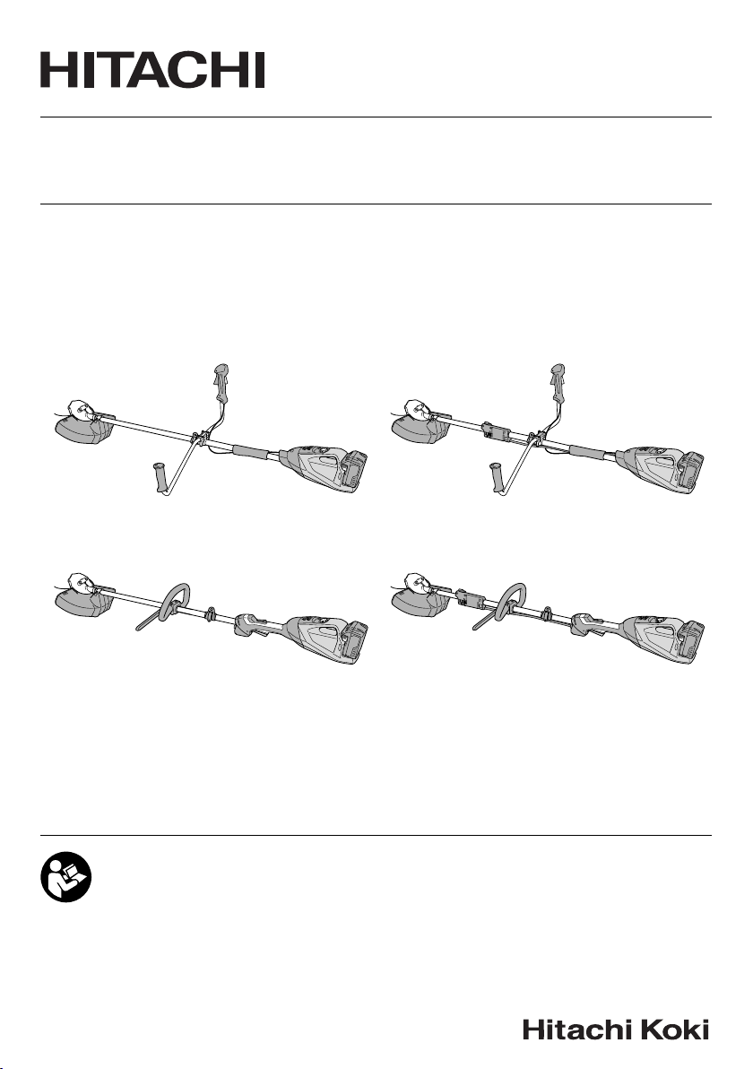
CG 36DA • CG 36DA(L) • CG 36DTA • CG 36DTA(L)
CG36DA
CG36DA(L)
Handling instructions
CG36DTA
CG36DTA(L)
Page 2
1
A
C
K
B
H
G
F
E
I
D
J
C
L
I
D
CG36DA
CC
D
M
G
B
F
E
K
A
D
CG36DA(L)
N
A
B
K
H
G
F
E
J
CG36DTA
L
M
K
A
G
B
F
E
CG36DTA(L)
O
2345
3
5
1
8
9
1
@0
7
2
$
^
#
1
y
w
e
)
(
#
u
r
t
p
i
q
2
o
1
4
2
6
6789
*
!
%
&
Page 3
10 11 12 13
s
d
a
a
g
f
#
î
Å
∏
Ø
h
14 15 16 17
j
∏
Î
7
Í
∏
Î
7
k
l
î
Å
∏
Ø
#
18 19 20 21
a
v
c
z
/
,
m
/
x
b
n
c
;
22 23 24 25
¶
•
c
.
¶
¡
§
ª
28
26 27
150 mm
b
§
⁄
§
‹
2.38 mm
™
1.68 mm
¢
∞
£
º
100 – 150 mm
fi
fl
¤
›
3
Page 4
29 30 31 32
‡
!
!
‚
°
·
·
‚
‡
Œ
¡
°
33 34 35 36
·
‚
·
‚
37 38 39
´
#
i
b
„
40 41
ˇ
4 mm
10 mm
Ü
ˇ
Á
‰
4
Page 5
42
43
ab
1
2
44
2
1
5
Page 6
SYMBOLS
WARNING
The following show symbols used for the machine.
Be sure that you understand their meaning before
use.
CG36DA / CG36DA (L) / CG36DTA / CG36DTA (L):
Cordless Grass Trimmer
To reduce the risk of injury, user must read
instruction manual.
Always wear eye protection.
Always wear hearing protection.
Do not expose to moisture.
Keep bystanders away.
Remove battery before adjusting or cleaning
and before leaving the machine unattended for
any period.
It is important that you read, fully understand and
observe the following safety precautions and
warnings. Careless or improper use of the unit may
cause serious or fatal injury.
Read, understand and follow all warnings and
instructions in this manual and on the unit.
Prohibited action
Always wear eye, head and ear protectors when
using this unit.
Keep all children, bystanders and helpers
15 m away from the unit. If anyone approaches
you, stop the unit and cutting attachment
immediately.
Be careful of thrown objects.
Shows maximum shaft speed. Do not use the
Max
cutting attachment whose max rpm is below the
-1
8,000 min
shaft rpm.
Gloves should be worn when necessary, e.g.,
when assembling cutting equipment.
Use anti-slip and sturdy footwear.
Blade thrust may occur when the spinning
blade contacts a solid object in the critical area.
A dangerous reaction may occur causing the
entire unit and operator to be thrust violently.
This reaction is called blade thrust. As a result,
the operator may lose control of the unit which
may cause serious or fatal injury. Blade thrust is
more likely to occur in areas where it is diffi cult
to see the material to be cut.
Power button
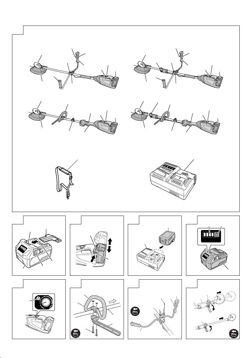
WHAT IS WHAT? (Fig. 1)
A: Lever: Trigger for activating the unit.
B: Lock lever: Lever that prevents the accidental operation
of the trigger.
C: Motor: Battery-driven, disk-shaped motor.
D: Cover: Protects operator from fl ying debris.
E: Battery: Power source to drive the unit.
F: Power button: Button for switching the units power unit's
power ON or OFF.
G: Speed dial: Dial for adjusting the speed of the motor.
H: Handle right: Handle with lever located on the right side
of the unit.
I: Handle left: Handle located on the left side of the unit.
J: Handle fi xture: Secures the handle to the unit.
K: Hang: Used for attaching a shoulder or hanger belt to the
unit.
L: Fixing lever
M: Loop handle
N: Shoulder belt: Harness with release mechanism for
combined use with battery.
O: Charger: For charging the battery.
GENERAL POWER TOOL SAFETY
WARNINGS
WARNING
Read all safety warnings and all instructions.
Failure to follow the warnings and instructions may result in
electric shock, fi re and/or serious injury.
Save all warnings and instructions for future reference.
The term “power tool” in the warnings refers to your mainsoperated (corded) power tool or battery-operated (cordless)
power tool.
1) Work area safety
a) Keep work area clean and well lit.
Cluttered or dark areas invite accidents.
b) Do not operate power tools in explosive
atmospheres, such as in the presence of
fl ammable liquids, gases or dust.
Power tools create sparks which may ignite the dust
or fumes.
c) Keep children and bystanders away while
operating a power tool.
Distractions can cause you to lose control.
2) Electrical safety
a) Power tool plugs must match the outlet.
Never modify the plug in any way.
Do not use any adapter plugs with earthed
(grounded) power tools.
Unmodifi ed plugs and matching outlets will reduce
risk of electric shock.
b) Avoid body contact with earthed or grounded
surfaces, such as pipes, radiators, ranges and
refrigerators.
There is an increased risk of electric shock if your
body is earthed or grounded.
c) Do not expose power tools to rain or wet
conditions.
Water entering a power tool will increase the risk of
electric shock.
d) Do not abuse the cord. Never use the cord for
carrying, pulling or unplugging the power tool.
Keep cord away from heat, oil, sharp edges or
moving parts.
Damaged or entangled cords increase the risk of
electric shock.
e) When operating a power tool outdoors, use an
extension cord suitable for outdoor use.
6
Page 7

Use of a cord suitable for outdoor use reduces the
risk of electric shock.
f) If operating a power tool in a damp location
is unavoidable, use a residual current device
(RCD) protected supply.
Use of an RCD reduces the risk of electric shock.
3) Personal safety
a) Stay alert, watch what you are doing and use
common sense when operating a power tool.
Do not use a power tool while you are tired
or under the infl uence of drugs, alcohol or
medication.
A moment of inattention while operating power tools
may result in serious personal injury.
b) Use personal protective equipment. Always
wear eye protection.
Protective equipment such as dust mask, non-skid
safety shoes, hard hat, or hearing protection used for
appropriate conditions will reduce personal injuries.
c) Prevent unintentional starting. Ensure the
switch is in the off position before connecting to
power source and/or battery pack, picking up or
carrying the tool.
Carrying power tools with your fi nger on the switch
or energising power tools that have the switch on
invites accidents.
d) Remove any adjusting key or wrench before
turning the power tool on.
A wrench or a key left attached to a rotating part of
the power tool may result in personal injury.
e) Do not overreach. Keep proper footing and
balance at all times.
This enables better control of the power tool in
unexpected situations.
f) Dress properly. Do not wear loose clothing or
jewellery. Keep your hair, clothing and gloves
away from moving parts.
Loose clothes, jewellery or long hair can be caught in
moving parts.
g) If devices are provided for the connection of
dust extraction and collection facilities, ensure
these are connected and properly used.
Use of dust collection can reduce dust related
hazards.
4) Power tool use and care
a) Do not force the power tool. Use the correct
power tool for your application.
The correct power tool will do the job better and safer
at the rate for which it was designed.
b) Do not use the power tool if the switch does not
turn it on and off .
Any power tool that cannot be controlled with the
switch is dangerous and must be repaired.
c) Disconnect the plug from the power source and/
or the battery pack from the power tool before
making any adjustments, changing accessories,
or storing power tools.
Such preventive safety measures reduce the risk of
starting the power tool accidentally.
d) Store idle power tools out of the reach of
children and do not allow persons unfamiliar
with the power tool or these instructions to
operate the power tool.
Power tools are dangerous in the hands of untrained
users.
e) Maintain power tools. Check for misalignment
or binding of moving parts, breakage of parts
and any other condition that may aff ect the
power toolʼs operation.
If damaged, have the power tool repaired before
use.
Many accidents are caused by poorly maintained
power tools.
f) Keep cutting tools sharp and clean.
Properly maintained cutting tools with sharp cutting
edges are less likely to bind and are easier to control.
g) Use the power tool, accessories and tool bits
etc. in accordance with these instructions,
taking into account the working conditions and
the work to be performed.
Use of the power tool for operations diff erent from
those intended could result in a hazardous situation.
5) Battery tool use and care
a) Recharge only with the charger specifi ed by the
manufacturer.
A charger that is suitable for one type of battery pack
may create a risk of fi re when used with another
battery pack.
b) Use power tools only with specifi cally
designated battery packs.
Use of any other battery packs may create a risk of
injury and fi re.
c) When battery pack is not in use, keep it away
from other metal objects, like paper clips, coins,
keys, nails, screws or other small metal objects,
that can make a connection from one terminal to
another.
Shorting the battery terminals together may cause
burns or a fi re.
d) Under abusive conditions, liquid may be ejected
from the battery; avoid contact. If contact
accidentally occurs, fl ush with water. If liquid
contacts eyes, additionally seek medical help.
Liquid ejected from the battery may cause irritation or
burns.
6) Service
a) Have your power tool serviced by a qualifi ed
repair person using only identical replacement
parts.
This will ensure that the safety of the power tool is
maintained.
PRECAUTION
Keep children and infi rm persons away.
When not in use, tools should be stored out of reach of
children and infi rm persons.
GRASS TRIMMER SAFETY
WARNINGS
IMPORTANT
READ CAREFULLY BEFORE USE
KEEP FOR FUTURE REFERENCE
Safe operation practices
● Training
a) Read the instructions carefully. Be familiar with the
controls and the correct use of the machine.
b) Never allow people unfamiliar with these instructions
or children to use the machine. Local regulations can
restrict the age of the operator.
c) Keep in mind that the operator or user is responsible for
accidents or hazards occurring to other people or their
property.
● Preparation
a) Before use check the supply and extension cord for
signs of damage or aging. If the cord becomes damaged
during use, disconnect the cord from the supply
immediately.
DO NOT TOUCH THE CORD BEFORE
DISCONNECTING THE SUPPLY.
Do not use the machine if the cord is damaged or worn.
7
Page 8

b) Before use, always visually inspect the machine for
damaged, missing or misplaced guards or shields.
c) Never operate the machine while people, especially
children, or pets are nearby.
d) Never replace nylon head with metalic cutting means.
● Operation
a) Wear eye protection, stout shoes and long trousers at all
times while operating the machine.
b) Avoid using the machine in bad weather conditions
especially when there is a risk of lightning.
c) Use the machine only in daylight or good artifi cial light.
d) Never operate the machine with damaged guards or
shields or without guards or shields in place.
e) Switch on the motor only when the hands and feet are
away from the cutting means.
f) Always disconnect the machine from the power supply
(i.e. remove the plug from the mains or remove the
disabling device)
– whenever the machine is left unattended;
– before clearing a blockage;
– before checking, cleaning or working on the machine;
– after striking a foreign object;
– whenever the machine starts vibrating abnormally.
g) Take care against injury to feet and hands from the
cutting means.
h) Always ensure that the ventilation openings are kept
clear of debris.
i) Never modify the unit/machine in any way. Do not use
your unit/machine for any job except that for which it is
intended.
● Maintenance, transport and storage
a) Disconnect the machine from the power supply (i.e.
remove the plug from the mains or remove the disabling
device) before carrying out maintenance or cleaning
work.
b) Use only the manufacturer’s recommended
replacement parts and accessories.
c) Inspect and maintain the machine regularly. Have the
machine repaired only by an authorized repairer.
d) When not in use, store the machine out of the reach of
children.
e) When transporting in a vehicle or storage, cover blade
with blade cover.
PRECAUTIONS FOR CORDLESS
GRASS TRIMMER
WARNING
1. Exercise patience in all work with the tool. And dress
properly to keep warm.
2. Plan all work ahead to prevent accidents.
3. Do not operate the tool at night or under bad weather
conditions when visibility is poor. And do not operate the
tool when it is raining or right after it has been raining.
Working on slippery ground could lead to an accident if
you lose your balance.
4. Inspect the nylon head before starting work.
Do not use the tool if the nylon head is cracked, scarred
or bent.
Make sure the nylon head is properly attached. A nylon
head that falls apart or comes loose during operation
could cause an accident.
5. Be sure to attach the cover before starting work.
Operating the tool without this parts could lead to injury.
6. Be sure to attach the loop handle before starting work.
Make sure it is not loose but properly attached before
starting work. Hold the loop handle fi rmly during work
and do not swing the tool around, but use the correct
posture and maintain your balance.
Losing your balance during work could lead to an injury.
8
7. Take care when starting the motor.
Place the tool on level ground.
Do not operate the tool within 15 m of people or animals.
Make sure that the nylon head does not come into
contact with the ground or trees and plants.
A careless start could lead to injury.
8. Do not secure the lock lever.
Accidentally pulling back the lever could lead to
unexpected injury.
9. Before leaving the tool, press the power button to turn it
off .
10. Operate the tool with care near electric cables, gas pipes
and similar installations.
11. Look out for and remove empty cans, wire, stones or
other obstacles before starting work. And do not work
near tree roots or rocks.
Working in such areas could damage the nylon head or
lead to injury.
12. Never touch the nylon head during operation.
Also make sure it does not come into contact with your
hair, clothes, etc.
13. In the following situations, turn off the motor and check
that the nylon head has stopped rotating.
To move to another work area.
To remove rubbish or grass that has become stuck in the
tool.
To remove from the work area obstacles or the rubbish,
grass and chips generated by trimming.
To lay down the tool.
Doing this with the nylon head still rotating could lead to
unexpected accidents.
14. Do not use the tool within 15 m of another person.
When you work with someone else, maintain a distance
of more than 15 m.
Flying chips could lead to unexpected accidents.
When working on unstable surfaces like slopes, make
sure that your co-worker is not exposed to any hazards.
Use whistles or other means for calling the attention of
your co-workers.
15. When grass and other objects become entangled in the
nylon head, turn off the motor and make sure the nylon
head has stopped rotating before removing them.
Removing objects from the nylon head when it is still
rotating will lead to injury.
Continuing operation when foreign matter is stuck in the
nylon head may lead to damage.
16. If the tool is operating poorly and produces strange noise
or vibrations, turn off the motor immediately and ask your
dealer to have it inspected and repaired.
Continued use under these conditions could lead to
injury or tool damage.
17. If you drop or bump the tool, inspect it carefully to check
there is no damage, cracks or deformation.
Using a tool that is damaged, cracked or deformed could
result in injury.
18. Secure the tool during vehicle transport to ensure that it
lies still.
Failure to heed this warning may result in an accident.
19. This product contains a strong permanent magnet in the
motor.
Observe the following precautions regarding adhering of
chips to the tool and the eff ect of the permanent magnet
on electronic devices.
20. Do not use the product if the tool or the battery terminals
(battery mount) are deformed.
Installing the battery could cause a short circuit that
could result in smoke emission or ignition.
21. Keep the tool’s terminals (battery mount) free of swarf
and dust.
○ Prior to use, make sure that swarf and dust have not
collected in the area of the terminals.
○ During use, try to avoid swarf or dust on the tool from
falling on the battery.
Page 9

○ When suspending operation or after use, do not leave
the tool in an area where it may be exposed to falling
swarf or dust.
Doing so could cause a short circuit that could result in
smoke emission or ignition.
CAUTION
○ Do not place the tool on a workbench or work area where
metal chips are present.
The chips may adhere to the tool, resulting in injury or
malfunction.
○ If chips have adhered to the tool, do not touch it. Remove
the chips with a brush.
Failure to do so may result in injury.
○ If you use a pacemaker or other electronic medical
device, do not operate or approach the tool.
Operation of the electronic device may be aff ected.
○ Do not use the tool in the vicinity of precision devices
such as cell phones, magnetic cards or electronic
memory media.
Doing so may lead to misoperation, malfunction or loss
of data.
CAUTION
1. Do not turn on the nylon head for cutting objects other
than grass. Do not operate the tool in water puddles and
make sure that soil does not come into contact with the
nylon head.
2. The tool contains precision parts and should not be
dropped, exposed to strong impact or water.
The tool could be damaged or malfunction.
3. When the tool is to be stored after use or be transported,
remove the nylon head.
4. Do not expose the tool to insecticide and other
chemicals.
Such chemicals could cause cracking and other
damage.
5. Replace warning labels with new labels when they
become diffi cult to recognize or illegible and when they
start to peel.
Ask your dealer to provide the warning labels.
6. Do not touch the motor immediately after use since it
may be very hot.
PRECAUTIONS FOR BATTERY AND
CHARGER
1. Always charge the battery at an ambient temperature of
-10–40°C. A temperature of less than -10°C will result in
over charging which is dangerous. The battery cannot be
charged at a temperature greater than 40°C.
The most suitable temperature for charging is that of
20–25°C.
2. Do not use the charger continuously.
When one charging is completed, leave the charger for
about 15 minutes before the next charging of battery.
3. Do not allow foreign matter to enter the hole for
connecting the rechargeable battery.
4. Never disassemble the rechargeable battery or charger.
5. Never short-circuit the rechargeable battery.
Short-circuiting the battery will cause a great electric
current and overheat. It results in burn or damage to the
battery.
6. Do not dispose of the battery in fi re.
If the battery is burnt, it may explode.
7. Using an exhausted battery will damage the charger.
8. Bring the battery to the shop from which it was purchased
as soon as the post-charging battery life becomes too
short for practical use. Do not dispose of the exhausted
battery.
9. Do not insert objects into the air ventilation slots of the
charger.
Inserting metal objects or fl ammable into the charger air
ventilation slots will result in an electrical shock hazard or
damage to the charger.
CAUTION ON LITHIUM-ION BATTERY
To extend the lifetime, the lithium-ion battery equips with the
protection function to stop the output.
In the cases of 1 to 3 described below, when using this
product, even if you are pulling the switch, the motor may
stop. This is not the trouble but the result of protection
function.
1. When the battery power remaining runs out, the motor
stops.
In such case, charge it up immediately.
2. If the tool is overloaded, the motor may stop. In this
case, release the switch of tool and eliminate causes of
overloading. After that, you can use it again.
3. If the battery is overheated under overload work, the
battery power may stop.
In this case, stop using the battery and let the battery
cool. After that, you can use it again.
Furthermore, please heed the following warning and caution.
WARNING
In order to prevent any battery leakage, heat generation,
smoke emission, explosion and ignition beforehand, please
be sure to heed the following precautions.
1. Make sure that swarf and dust do not collect on the
battery.
○ During work make sure that swarf and dust do not fall on
the battery.
○ Make sure that any swarf and dust falling on the power
tool during work do not collect on the battery.
○ Do not store an unused battery in a location exposed to
swarf and dust.
○ Before storing a battery, remove any swarf and dust that
may adhere to it and do not store it together with metal
parts (screws, nails, etc.).
2. Do not pierce battery with a sharp object such as a
nail, strike with a hammer, step on, throw or subject the
battery to severe physical shock.
3. Do not use an apparently damaged or deformed battery.
4. Do not use the battery in reverse polarity.
5. Do not connect directly to an electrical outlets or car
cigarette lighter sockets.
6. Do not use the battery for a purpose other than those
specifi ed.
7. If the battery charging fails to complete even when a
specifi ed recharging time has elapsed, immediately stop
further recharging.
8. Do not put or subject the battery to high temperatures or
high pressure such as into a microwave oven, dryer, or
high pressure container.
9. Keep away from fi re immediately when leakage or foul
odor are detected.
10. Do not use in a location where strong static electricity
generates.
11. If there is battery leakage, foul odor, heat generated,
discolored or deformed, or in any way appears abnormal
during use, recharging or storage, immediately remove it
from the equipment or battery charger, and stop use.
12. Do not immerse the battery or allow any fl uids to fl ow
inside. Conductive liquid ingress, such as water, can
cause damage resulting in fi re or explosion. Store your
battery in a cool, dry place, away from combustible and
fl ammable items. Corrosive gas atmospheres must be
avoided.
CAUTION
1. If liquid leaking from the battery gets into your eyes,
do not rub your eyes and wash them well with fresh
clean water such as tap water and contact a doctor
immediately.
If left untreated, the liquid may cause eye-problems.
2. If liquid leaks onto your skin or clothes, wash well with
clean water such as tap water immediately.
There is a possibility that this can cause skin irritation.
9
Page 10

3. If you fi nd rust, foul odor, overheating, discolor,
deformation, and/or other irregularities when using the
battery for the fi rst time, do not use and return it to your
supplier or vendor.
WARNING
If an electrically conductive foreign object enters the
terminals of the lithium ion battery, a short-circuit may occur
resulting in the risk of fi re. Please observe the following
matters when storing the battery.
○ Do not place electrically conductive cuttings, nails,
steel wire, copper wire or other wire in the storage
case.
○ Either install the battery in the power tool or store
by securely pressing into the battery cover until the
ventilation holes are concealed to prevent shortcircuits (See Fig. 2).
REGARDING LITHIUM-ION BATTERY
TRANSPORTATION
When transporting a lithium-ion battery, please observe the
following precautions.
WARNING
Notify the transporting company that a package contains a
lithium-ion battery, inform the company of its power output
and follow the instructions of the transportation company
when arranging transport.
○ Lithium-ion batteries that exceed a power output of
100Wh are considered to be in the freight classifi cation
of Dangerous Goods and will require special application
procedures.
○ For transportation abroad, you must comply with
international law and the rules and regulations of the
destination country.
Power Output
Wh
2 to 3 digit number
USB DEVICE CONNECTION
PRECAUTIONS (UC18YSL3)
When an unexpected problem occurs, the data in a USB
device connected to this product may be corrupted or lost.
Always make sure to back up any data contained in the USB
device prior to use with this product.
Please be aware that our company accepts absolutely no
responsibility for any data stored in a USB device that is
corrupted or lost, nor for any damage that may occur to a
connected device.
WARNING
○ Prior to use, check the connecting USB cable for any
defect or damage.
Using a defective or damaged USB cable can cause
smoke emission or ignition.
○ When the product is not being used, cover the USB port
with the rubber cover.
Buildup of dust etc. in the USB port can cause smoke
emission or ignition.
NOTE
○ There may be an occasional pause during USB
recharging.
○ When a USB device is not being charged, remove the
USB device from the charger.
Failure to do so may not only reduce the battery life
of a USB device, but may also result in unexpected
accidents.
○ It may not be possible to charge some USB devices,
depending on the type of device.
10
Page 11

DESCRIPTION OF NUMBERED ITEMS (Fig. 2 – Fig. 41)
Battery
1
Latch
2
Battery cover
3
Terminals
4
Ventilation holes
5
Push
6
Insert
7
Pull out
8
Charge indicator lamp
9
Battery level indicator
0
switch
Power button
!
Battery level indicator
@
lamp
Main pipe
#
Housing side
$
Loop handle
%
Handle fi xture
^
M6×43 bolts
&
M6 nuts
*
Handle right
(
Lever
)
Handle left
q
Handle fi xture
w
M5 × 25 hex. Socket
e
bolts
Locking lever
r
Release
t
Extend
y
Holder case
u
Lock
i
Projection of locking
o
lever
Hole
p
Cover
a
Knife
s
D5 tapping screw
d
Cover bracket
f
M6×25 hex. socket
g
button bolts
Cover holder
h
Flange ass’y
j
Wing
k
Motor case
l
Hex. bar wrench 4 mm
;
Threaded fastener of
z
the motor case
Hole
x
Nylon head
c
Screw (left rotation)
v
Nylon line
b
Tap
n
Button
m
Tap/release
,
Wear limit mark
.
(2 marks)
Extends in 30 mm
/
increments
Appropriate length
¡
90 – 110 mm
Cover
™
Case
£
Hook
¢
Press tabs (2 areas)
∞
Reel
§
Groove
¶
Fold back the middle
•
part
Direction to wind nylon
ª
cord
Secure in the stopper
º
Stopper
⁄
Eyelet line guide
¤
While holding the reel
‹
String the line through
›
the eyelet line guide
Locking holes of cover
fi
(2 holes)
Tabs of case (2 tabs)
fl
Power lamp
‡
Handle
°
Lock lever
·
Lever
‚
Speed dial
Œ
Projection of locking
„
lever
Wear limit
´
Brush cap
‰
Nail of carbon brush
ˇ
Protrusion of carbon
Á
brush
Contact portion of
Ü
brush tube
Pull
î
Hanger
Ø
Bracket
∏
Quick-release belt
Å
Hook
Í
Quick-release bracket
Î
11
Page 12

SPECIFICATIONS
POWER TOOL
Model CG36DA CG36DA(L) CG36DTA CG36DTA(L)
Voltage 36 V
Pole type Straight type Extendable type
Cutting capacity diameter 310 mm
Rotation direction Counterclockwise as seen from above
No-load speed 5800 – 7000 /min
Operating time on one charge*
(When supplied rechargeable battery is
fully charged)
Battery available for this tool** BSL36A18
Weight (with nylon head, rechargeable
battery, shoulder belt and cover)
The data in the above table is provided only as an example. Since type of grass, ambient temperature, rechargeable
*
battery characteristics, work methods, etc. can vary widely the above should only be used as a rough guideline.
Conditions: Outer diameter of nylon head 310 mm, speed dial set to Normal or High. (lever left ON all the time)
**
Existing batteries (BSL3660/3620/3626, BSL18xx series, etc.) cannot be used with this tool.
BSL36A18
42 min (Normal)
18 min (High)
5.4 kg 5.1 kg 5.8 kg 5.5 kg
BATTERY
Model BSL36A18
Voltage 36 V / 18 V (Automatic Switching*)
Battery capacity
Available cordless
products**
Available charger
* The tool itself will automatically switch over.
** Please see our general catalogue for details.
CHARGER
Model UC18YSL3
Charging voltage 14.4 V – 18 V
Weight 0.6 kg
2.5 Ah / 5.0 Ah
(Automatic Switching*)
Multi volt series, 18V product
Sliding charger for lithium ion
batteries
STANDARD ACCESSORIES
In addition to the main unit (1 unit), the package contains the
accessories listed on page 20.
Standard accessories are subject to change without notice.
OPTIONAL ACCESSORIES (sold
separately) (Page 21)
Optional accessories are subject to change without notice.
APPLICATIONS
Trimming, scaling and mowing of weed.
BATTERY REMOVAL/INSTALLATION
1. Battery removal
Hold the housing tightly and push the battery latches to
remove the battery (see Fig. 3).
CAUTION
Never short-circuit the battery.
2. Battery installation
Insert the battery while observing its polarities (see
Fig. 3).
CHARGING
Before using the power tool, charge the battery as follows.
1. Connect the charger’s power cord to the receptacle.
When connecting the plug of the charger to a receptacle,
the charge indicator lamp will blink in red (At 1- second
intervals).
2. Insert the battery into the charger.
Firmly insert the battery into the charger as shown in
Fig. 4 (on page 2).
3. Charging
When inserting a battery in the charger, the charge
indicator lamp will blink in blue.
When the battery becomes fully recharged, the charge
indicator lamp will light up in green. (See Table 1)
(1) Charge indicator lamp indication
The indications of the charge indicator lamp will be as
shown in Table 1, according to the condition of the
charger or the rechargeable battery.
12
Page 13

Table 1
Indications of the charge indicator lamp
Before
charging
While
charging
Charge
indicator
lamp
(RED /
BLUE /
GREEN /
PURPLE)
(2) Regarding the temperatures and charging time of the rechargeable battery
The temperatures and charging time will become as shown in Table 2.
Battery
USB
NOTE
The recharging time may vary according to the ambient temperature and power source voltage.
4. Disconnect the charger’s power cord from the
5. Hold the charger fi rmly and pull out the battery.
NOTE
Be sure to pull out the battery from the charger after
Charging
complete
Overheat
standby
Charging
impossible
Type of battery Li-ion
Temperatures at which the
battery can be recharged
Charging voltage V 14.4 18
Charging time,
approx. (At 20°C)
Charging voltage V 5
Charging current A 2
receptacle.
use, and then keep it.
Blinks
(RED)
Blinks
(BLUE)
Blinks
(BLUE)
Lights
(BLUE)
Lights
(GREEN)
Blinks
(RED)
Flickers
(PURPLE)
Charger
Lights for 0.5 seconds. Does not light for
0.5 seconds. (off for 0.5 seconds)
Lights for 0.5 seconds. Does not light for
1 second. (off for 1 second)
Lights for 1 second. Does not light
for 0.5 seconds. (off for 0.5 seconds)
Lights continuously
Lights continuously
(Continuous buzzer sound: about 6
seconds)
Lights for 0.3 seconds. Does not light for
0.3 seconds. (off for 0.3 seconds)
Lights for 0.1 seconds. Does not light for
0.1 seconds. (off for 0.1 seconds)
(Intermittent buzzer sound: about 2
seconds)
Table 2
BSL14xx series BSL18xx series
(4 cells) (8 cells) (5 cells) (10 cells) (10 cells)
BSL1415S : 15
BSL1415
:
15
min.
BSL1415X
BSL1420
BSL1425
BSL1430C
:
:
:
:
15
20
25
30
BSL1430
BSL1440
BSL1450
BSL1460
Plugged into power source
Battery capacity at less than 50%
Battery capacity at less than 80%
Battery capacity at more than 80%
Battery overheated. Unable to
charge. (Charging will commence
when battery cools)
Malfunction in the battery or the
charger
UC18YSL3
-10°C – 50°C
BSL1815S : 15
BSL1815 : 15
:
20
BSL1815X : 15
:
26
BSL1820 : 20
:
32
BSL1825 : 25
:
38
BSL1830C : 30
Regarding electric discharge in case of new
batteries, etc.
As the internal chemical substance of new batteries and
batteries that have not been used for an extended period
is not activated, the electric discharge might be low when
using them the fi rst and second time. This is a temporary
phenomenon, and normal time required for recharging
will be restored by recharging the batteries 2 – 3 times.
BSL1830 : 20
BSL1840 : 26
BSL1850 : 32
BSL1860 : 38
Multi volt
series
BSL36A18 : 32
13
Page 14

How to make the batteries perform longer.
(1) Recharge the batteries before they become completely
exhausted.
When you feel that the power of the tool becomes
weaker, stop using the tool and recharge its battery. If
you continue to use the tool and exhaust the electric
current, the battery may be damaged and its life will
become shorter.
(2) Avoid recharging at high temperatures.
A rechargeable battery will be hot immediately after
use. If such a battery is recharged immediately after
use, its internal chemical substance will deteriorate, and
the battery life will be shortened. Leave the battery and
recharge it after it has cooled for a while.
CAUTION
○ If the battery is charged while it is heated because
it has been left for a long time in a location subject to
direct sunlight or because the battery has just been
used, the charge indicator lamp of the charger lights
for 0.3 seconds, does not light for 0.3 seconds (off for
0.3 seconds). In such a case, fi rst let the battery cool,
then start charging.
○ When the charge indicator lamp fl ickers (at 0.2-second
intervals), check for and take out any foreign objects in
the charger’s battery connector. If there are no foreign
objects, it is probable that the battery or charger is
malfunctioning. Take it to your authorized Service
Center.
○ Since the built-in micro computer takes about
3 seconds to confi rm that the battery being charged with
UC18YSL3 is taken out, wait for a minimum of 3 seconds
before reinserting it to continue charging. If the battery
is reinserted within 3 seconds, the battery may not be
properly charged.
ABOUT POWER LAMP
The power lamp indicates various statuses for the tool.
(Fig. 30)
Table 3 shows the various statuses indicated by the power
lamp.
Table 3
State of lamp Status of Tool
Off Power OFF
Red Power ON
Blinking red
Quickly blinking red The tool is operating abnormally.
The lever is being pressed while
the overload protection circuit of
the tool is operating.
REMAINING BATTERY INDICATOR
You can check the battery’s remaining capacity by pressing
the remaining battery indicator switch to light the indicator
lamp. (Fig. 5, Table 4)
The indicator will shut off approximately 3 seconds after the
remaining battery indicator switch is pressed.
It is best to use the remaining battery indicator as a
guide since there are slight diff erences such as ambient
temperature and the condition of the battery.
Also, the remaining battery indicator may vary from those
equipped to a tool or charger.
Table 4
State of lamp Battery Remaining Power
Lights ;
The battery remaining power is over
75%
Lights ;
The battery remaining power is
50% – 75%.
Lights ;
The battery remaining power is
25% – 50%.
Lights ;
The battery remaining power is less
than 25%
Blinks ;
The battery remaining power is nearly
empty. Recharge the battery soonest
possible.
Blinks ;
Output suspended due to high
temperature. Remove the battery from
the tool and allow it to fully cool down.
Blinks ;
Output suspended due to failure or
malfunction. The problem may be the
battery so please contact your dealer.
As the remaining battery indicator shows somewhat
diff erently depending on ambient temperature and battery
characteristics, read it as a reference.
NOTE
Do not give a strong shock to the switch panel or break it.
It may lead to a trouble.
PRIOR TO OPERATION
CAUTION
Pull out battery before doing any assembly.
1. Installing the loop handle (Fig. 7) (CG36DA (L),
CG36DTA (L) only)
(1) Remove the M6 × 43 bolts (2 pcs.).
(2) Install the loop handle on the main pipe so that it leans
against the housing.
(3) Place the handle fi xture at the lower end of the main pipe
and secure it fi rmly using M6 × 43 bolts (2 pcs.) and M6
nuts (2 pcs.).
NOTE
Secure the loop handle in a location that provides a good
grip.
CAUTION
Install the loop handle properly and securely as
instructed in the handling instructions.
If not attached properly or securely, it may come off and
cause injury.
2. Installing the bicycle-style handlebars (Fig. 8)
(1) Using the 4 mm hex wrench that is included, remove
the four bolts that have been temporarily secured to the
handle brace (A).
(2) Attach the right-hand side handgrip that has the lever
and the left-hand side handgrip, and then carefully
secure the handle brace (A) using the four bolts.
NOTE
Secure the left and right handgrips in a position that
provides a good grip.
CAUTION
Install the left and right handgrips properly and securely
as instructed in the handling instructions.
If not attached properly or securely, it may come off and
cause injury.
14
Page 15

3. Extending the main pipe (Fig. 9)
(1) Release the locking lever to allow the main pipe to be
extended.
(2) Extend the main pipe as far as it will go, making sure that
you hear it click.
NOTE
The motor will not operate unless the main pipe is fully
extended.
When you push the power button, the red power light will
fl ash rapidly.
(3) After extending the main pipe until it clicks, check that
the hole of the holder case is aligned with the hole of the
main pipe and lock the locking lever to fi x the main pipe
securely.
4. Installing cover (See Fig. 10 and 11)
WARNING
Be sure to install the cover in its designated location.
Failure to heed this warning may result in injury from
fl ying stones.
NOTE
Use the supplied hex. bar wrench 4 mm for installation.
(1) Use the supplied D5 tapping screw to install the knife in
the cover. (Fig. 10)
(2) Align the two holes in the cover bracket and the cover
and insert two M6 × 25 hex. socket button bolts. (The
cover bracket is installed in the motor case.)
(3) Place the cover holder on the underside of the cover and
use the supplied hex. bar wrench 4 mm to alternately
tighten the two M6 × 25 hex. socket button bolts until
they are properly tightened.
CAUTION
○ Take care to avoid cutting yourself on the knife inside the
cover.
○ Install the cover and knife properly and securely as
instructed in the handling instructions.
If not attached properly or securely, they may come off
and cause injury.
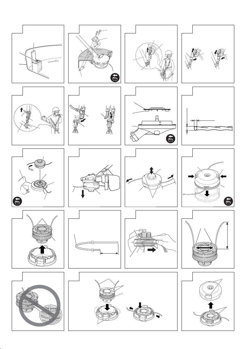
5. Installing the shoulder belt
Use in combination with a BSL36A18 battery.
WARNING
○ Be sure to attach the shoulder belt so that the grass
trimmer can be carried correctly.
○ If you get the feeling the tool is not operating normally,
turn off the motor immediately, remove the quick-release
bracket of the shoulder belt and remove the tool.
CAUTION
○ If you do not support the tool when you pull the quick-
release belt, it may fall causing injury or damage.
Hold the main pipe with one hand while you pull with the
other hand.
○ Make sure the quick-release function operates normally
before you start working.
(1) Place the shoulder belt on the shoulder as shown in
Fig. 12 (For use outside of Europe, see Fig. 14) and
engage it with the hanger on the tool. Adjust the shoulder
belt to suitable length.
(2) To remove the tool from the shoulder belt, support the
tool by holding the main pipe with one hand and use
the other hand to pull the quick-release belt as shown in
Fig. 12 (For use outside of Europe, see Fig. 14) to free it
from the bracket.
(3) To strap on the tool, insert the bracket in the hook and
insert the quick-release bracket over the hook and into
the wide opening of the bracket. (Fig. 13) (For use
outside of Europe, see Fig. 15)
Gently pull the shoulder belt to make sure that it is
properly attached.
NYLON HEAD
Installation of semi-auto nylon head
1. Function
Automatically feeds more nylon cutting line when it is
tapped.
Specifi cations
Code No.
335234
Applicable nylon cord
Cord diameter: Fig. 17
Length: 4 m
CAUTION
○ The case must be securely attached to the cover.
○ Check the cover, case and other components for cracks
○ Check the case and button for wear.
If the wear limit mark on the case is no longer visible or
○ The nylon head must be securely mounted to the
○ For outstanding performance and reliability, always
○ If the nylon head does not feed cutting line properly,
2. Installation (Fig. 16 and 18)
(1) Insert the fl ange assy into the motor case. At this time,
(2) Screw the nylon head directly to the threaded fastener of
The mounting nut of nylon head is left-hand-threaded.
CAUTION
Install the nylon head properly and securely as instructed
If not attached properly or securely, it may come off and
3. Adjustment of line length
Rotate and tap the nylon head on the ground. Nylon line
Also, you can extend nylon line with hands. This time the
Confi rm the line extends in 30 mm increments by
○ Appropriate Length of Nylon Line
The appropriate length of the line when the tool is in use
4. Nylon line replacement
(1) Prepare 4m of genuine nylon line in Fig. 17. (Code No.
(2) Press the opposing tabs, and then remove the cover
(3) Remove the reel from the case. (Fig. 22)
○ If there is nylon line remaining, hook the line in the
○ If the nylon line does not extend when there is enough
15
Type of
attaching
screw
Female
screw
or other damage.
there is a hole in the bottom of the button, change the
new parts immediately. (Fig. 20)
threaded fastener of the motor case.
use Hitachi nylon cutting line. Never use wire or other
materials that could become a dangerous projectile.
check that the nylon line and all components are
properly installed. Contact your Hitachi dealer if you
need assistance.
the wing of the fl ange assy should face the motor case
side. Next, align the holes of the fl ange assy and the
motor case, insert the hex. bar wrench 4 mm, and then
turn to tighten the fl ange assy.
the motor case.
Turn clockwise to loosen/ counterclockwise to tighten.
in the handling instructions.
cause injury.
is drawn out abt, 30 mm by one tapping. (Fig. 19)
motor must be completely stopped.
“tapping” and “releasing” the bottom button while pulling
the line ends of the nylon head. (Fig. 20)
is 90 – 110 mm. Extend the line to the appropriate length.
335235)
from the case. (Fig. 21)
groves, and then remove the reel.
nylon line remaining, or when replacing the nylon
line (Code No. 335235), wind the nylon line using the
following procedure.
Direction of rotation
Counterclockwise
Size of
attaching
screw
M10×
P1.25-LH
Page 16

(4) Release about 150 mm of the nylon cord from both ends,
fold the middle part and attach to the hook on the spool.
Next, wind the cord on the spool in the direction shown
by the arrow, being careful not to crisscross it (Fig. 23,
24).
(5) Leave about 100 mm – 150 mm nylon cord unwound,
hook and secure the line in the stopper. (Fig. 25)
NOTE
Do not cross the nylon line when securing the line in the
stopper. (Fig. 26)
(6) Align the position of the stopper and eyelet line guide,
and then insert the button through the case.
Release the line from the stopper while holding the reel
lightly, and then string the line through the eyelet line
guide. (Fig. 27)
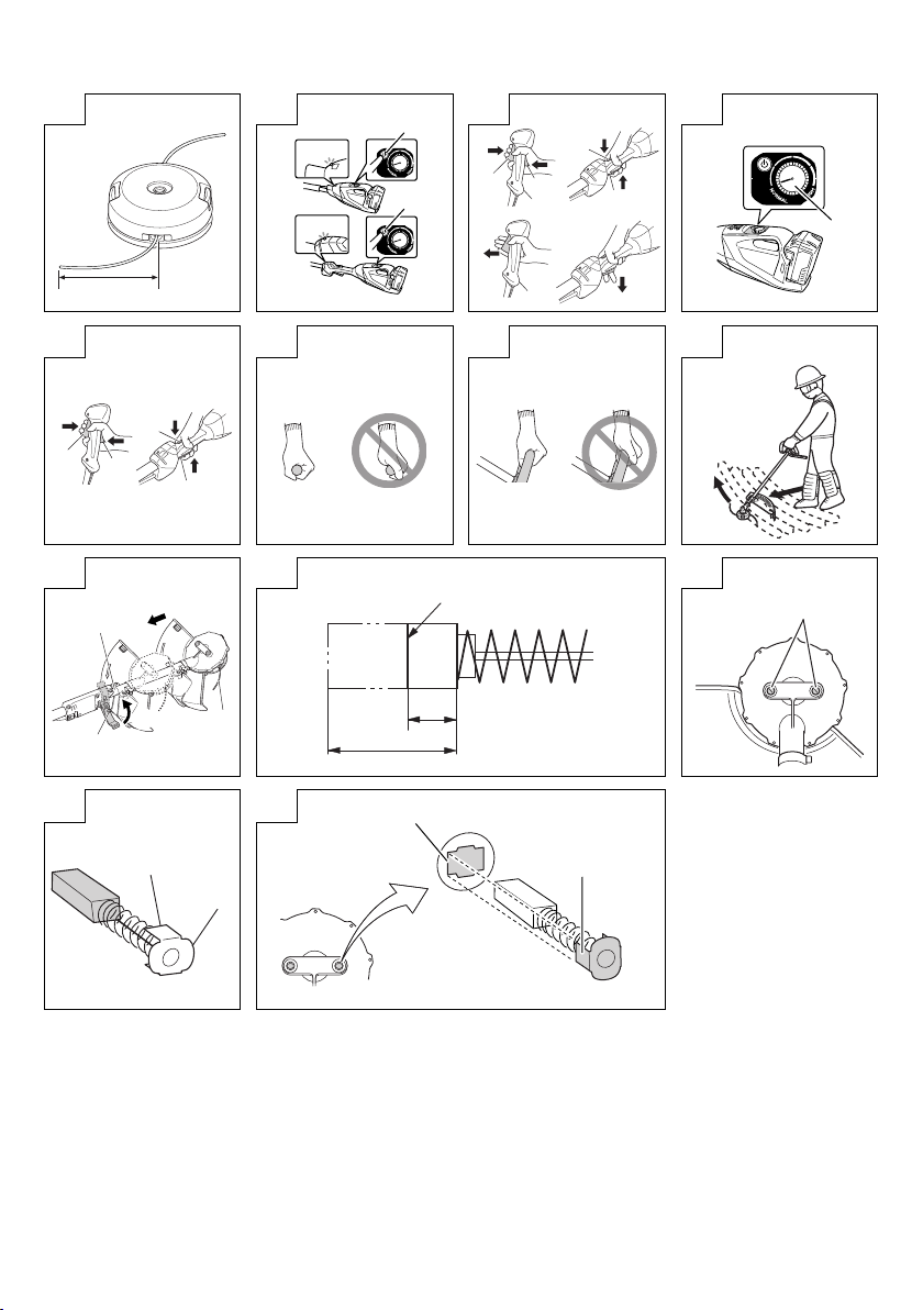
(7) Press and snap the tabs of the case in the locking holes
of the cover. (Fig. 28)
WARNING
Check to make sure the tabs are fi rmly snapped into the
locking holes.
Operating the tool while the parts are not fi rmly snapped
together may results in accidents or injury from fl ying
part.
(8) Pull the line taught so there is no slack, and then cut
the line to an extended length of 90 mm – 110 mm with
scissors. (Fig. 29)
OPERATION
Trimming grass
WARNING
○ Do not operate the tool at night or under bad weather
conditions when visibility is poor.
○ Do not operate the tool when it is raining or right after it
has been raining.
○ Wear proper footwear to prevent slipping that could
cause you to lose your balance and fall.
○ Do not use the tool on steep slopes.
When trimming grass on slopes that are not so steep,
trim by moving towards the ridge.
○ Place the right hand on the handle and the left hand on
the loop handle and hold it fi rmly.
○ Take care not to move the nylon head too close to your
feet.
○ Do not raise the nylon head above your knee during
cutting.
○ Do not use the tool where the nylon head may come into
contact with stones, tree and other obstacles.
○ A nylon head can injure while it continues to spin after
the motor is stopped. When the unit is turned off , make
sure the nylon head has stopped before the unit is set
down.
○ Do not use the tool within 15 m of another person. When
you work with someone else, maintain a distance of
more than 15 m.
1. Insert the battery while observing its polarities.
2. Turn on the tool. (Fig. 30)
○ Press the power button on the housing, the power goes
on and the power lamp on the housing or handle lights
red.
○ Pressing the power button a second time turns the power
off and the red lamp on the housing or handle goes off .
[Auto power off ]
When the power is turned on but the lever is not used for
one minute, the tool is automatically turned off . To turn
the tool on again, press the power button a second time.
WARNING
Never leave the tool with the power on. This could result
in an accident.
3. Lever operation and brake (Fig. 31)
To start rotation of the nylon head, with the power turned
on, pull the lever while pressing the locking lever.
When you release the lever, the brake engages in 1 – 3
seconds, stopping rotation of the nylon head.
Make sure that the brake operates normally before using
the tool.
4. Speed dial (Fig. 32)
A speed dial for changing the rotational speed in the
range of 5800 – 7000 /min is provided on the housing.
Turn the dial clockwise to increase the speed and
counterclockwise to reduce the speed.
5. Trimming grass
○ Grip the handle from above, press the locking lever and
pull the lever to start cutting head rotation. (Fig. 33)
○ Release the lever when you fi nish trimming and stop the
motor.
○ Place your thumb on the handle and grip the handle with
your other fi ngers. (Fig. 34) (CG36DA, CG36DTA only)
○ Place your thumb on the loop handle and grip the
handle with your other fi ngers. (Fig. 35) (CG36DA (L),
CG36DTA (L) only)
○ Take a posture that makes it easy to move.
[Grass trimming techniques]
Do not swing the pipe, but use the hips to move the nylon
head horizontally from right to left in an arc while going
forward and use the left side of the nylon head for cutting
grass. (Fig. 36)
OPERATIONAL CAUTIONS
Continuous work
This tool comes with an over-heat protection circuit
that protects the electronic parts that control the
rechargeable battery. In continuous trimming work, tool
temperature will rise and eventually trigger the over-heat
protection circuit, which will shut down the tool.
If this happens, let the tool cool for a length of time. When
the temperature drops, it will again become possible to
use the tool. When the rechargeable battery has to be
exchanged during continuous operation, let the tool rest
for about 15 minutes.
Overload Protection
This tool comes with an overload protection circuit
to protect the electronic parts controlling the tool. In
continuous overload during trimming work (locking the
nylon head, etc.), the overload protection circuit shuts
down the motor. If this happens, turn OFF the power,
and then resolve the problem causing the overload.
The power lamp blinks if the lever is pressed after the
motor has stopped (see page 14, “ABOUT POWER
LAMP”). The power automatically turns OFF if the power
lamp blinks longer than 5 seconds. If this happens,
resolve the problem causing the overload, and then
switch the power button ON to resume using the tool.
Carrying the tool (Fig. 37)
CAUTION
○ Remove the storage battery.
○ Carry the tool holding with hands.
○ When retracting the main pipe, be careful of the
pointed end and take care not get your fi ngers caught.
(CG36DTA, CG36DTA (L) only)
Release the locking lever and retract the main pipe. Lock
the locking lever until the projection hits the main pipe. This
procedure allows you to reduce the tool to a compact size.
The main pipe can be retracted to any position. Choose
a suitable length for carrying and storage. (CG36DTA,
CG36DTA (L) only)
16
Page 17

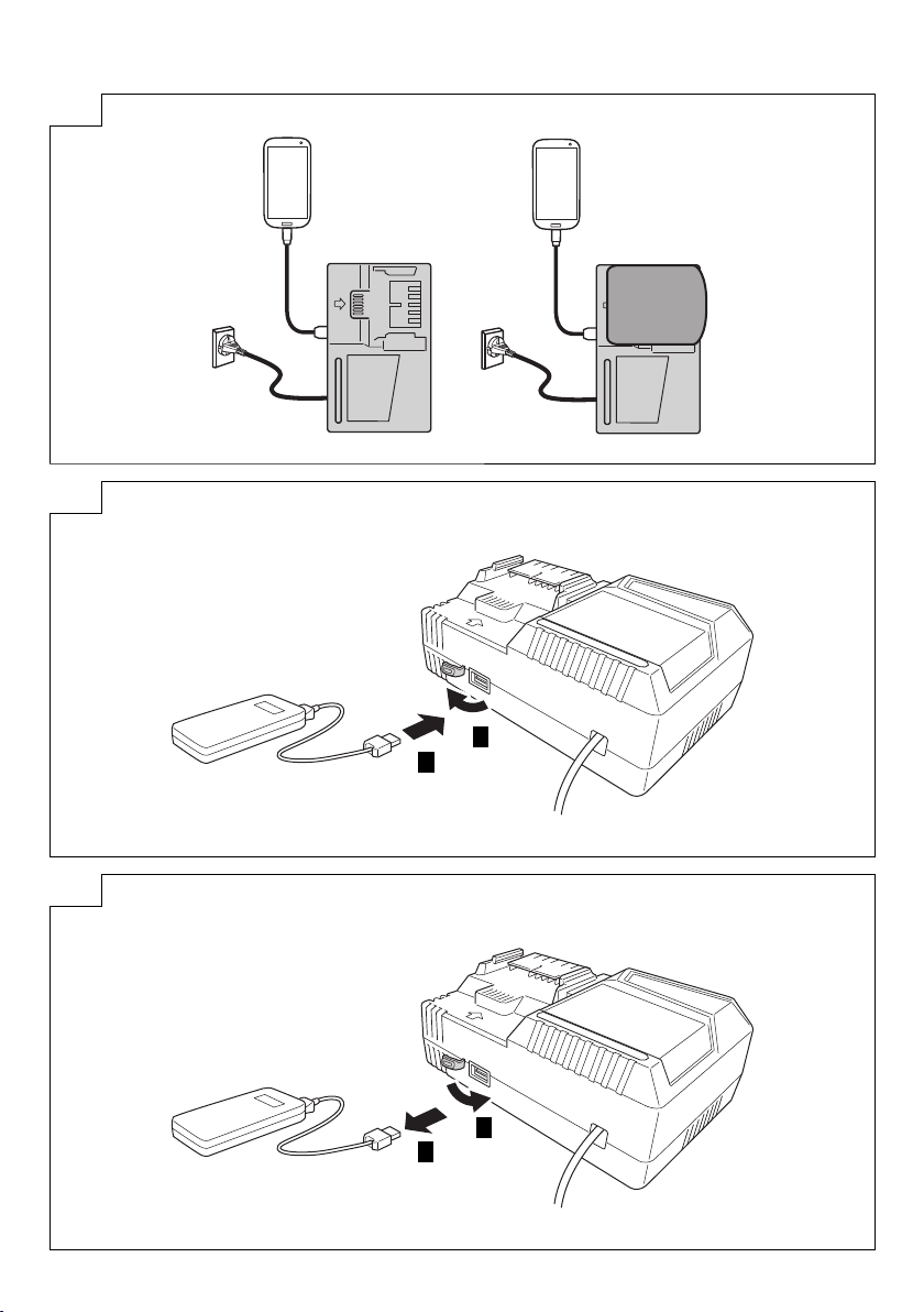
ABOUT USB DEVICE
○ Charging a USB device from an electrical outlet.
(Fig. 42-a)
○ Charging a USB device and battery from an electrical
outlet. (Fig. 42-b)
○ How to recharge USB device. (Fig. 43)
○ When charging of USB device is completed. (Fig. 44)
MAINTENANCE AND INSPECTION
CAUTION
Pull out battery before doing any inspection or
maintenance.
1. Checking the condition of the nylon head
The nylon head should be checked regularly. If worn or
broken nylon head can slip or decrease the effi ciency of
the motor and burn it out.
Replace worn nylon head with new ones.
CAUTION
If you use a nylon head of which point is worn or broken,
it will be dangerous. So replace it with a new one.
2. Check the Screws
Loose screws are dangerous. Regularly inspect them
and make sure they are tight.
CAUTION
Using this power tool with loosened screws is extremely
dangerous.
3. Inspecting the carbon brushes (Fig. 38)
The motor employs carbon brushes which are
consumable parts. Since and excessively worn carbon
brush can result in motor trouble, replace the carbon
brush with new ones when it becomes worn to or near
the “wear limit”. In addition, always keep carbon brushes
clean and ensure that they slide freely within the brush
holders.
NOTE
When replacing the carbon brush with a new one, be
sure to use the Hitachi Carbon Brush Code No. 999015.
4. Replacing carbon brushes
Take out the carbon brush by fi rst removing the brush
cap and then hooking the protrusion of the carbon
brush with a slotted head screw driver, etc., as shown in
Fig. 39.
When installing the carbon brush, choose the direction
so that the nail of the carbon brush (see Fig. 40) agrees
with the contact portion of brush tube. Then push it in
with a fi nger as illustrated in Fig. 41. Lastly, install the
brush cap.
CAUTION
○ Be absolutely sure to insert the nail of the carbon brush
into the contact portion of brush tube. (You can insert
whichever one of the two nails provided.)
○ Caution must be exercised since any error in this
operation can result in the deformed nail of the carbon
brush and may cause motor trouble at an early stage.
5. Inspection of terminals (tool and battery)
Check to make sure that swarf and dust have not
collected on the terminals.
On occasion check prior, during and after operation.
CAUTION
Remove any swarf or dust which may have collected on
the terminals.
Failure to do so may result in malfunction.
6. Cleaning of the outside
When the grass trimmer is stained, wipe with a soft dry
cloth or a cloth moistened with soapy water. Do not use
chloric solvents, gasoline or paint thinner, as they melt
plastics.
7. Storage
Store grass trimmer in a place in which the temperature
is less than 40°C and out of reach of children.
NOTE
Storing Lithium-ion Batteries
Make sure the lithium-ion batteries have been fully
charged before storing them.
Prolonged storage (3 months or more) of batteries with
a low charge may result in performance deterioration,
signifi cantly reducing battery usage time or rendering
the batteries incapable of holding a charge.
However, signifi cantly reduced battery usage time may
be recovered by repeatedly charging and using the
batteries two to fi ve times.
If the battery usage time is extremely short despite
repeated charging and use, consider the batteries dead
and purchase new batteries.
CAUTION
In the operation and maintenance of power tools, the
safety regulations and standards prescribed in each
country must be observed.
SELECTING ACCESSORIES
The accessories of this machine are listed on page 21.
Important notice on the batteries for the Hitachi
cordless power tools
Please always use one of our designated genuine
batteries. We cannot guarantee the safety and
performance of our cordless power tool when used with
batteries other than these designated by us, or when
the battery is disassembled and modifi ed (such as
disassembly and replacement of cells or other internal
parts).
NOTE
Due to HITACHI’s continuing program of research and
development, the specifi cations herein are subject to
change without prior notice.
17
Page 18

TROUBLESHOOTING
Use the inspections in the table below if the tool does not operate normally. If this does not remedy the problem, consult your
dealer or the Hitachi Authorized Service Center.
1. Power tool
Symptom Possible cause Remedy
Does not operate. The rechargeable battery is depleted. Charge the rechargeable battery.
The rechargeable battery has not been
properly installed.
The power has not been turned on. Press the power button on the housing to
The main pipe is not fully extended
(The red light blinks rapidly) (CG36DTA,
CG36DTA (L) only)
The lock lever was not pressed when the
lever was pulled back.
The tool pulls in large volumes of grass that
are caught between the cover and the nylon
head, the tool is overloaded.
The speed does not
change
Goes on, but soon
stops.
Strong vibrations. The loop handle is not properly attached to
The brake fails to
engage 1-3 seconds
after the lever is
released.
Battery cannot be
installed
The rechargeable battery power is low. Charge the rechargeable battery.
The rechargeable battery power is low. Charge the rechargeable battery.
The rechargeable battery is overheated. Stop using the rechargeable battery, remove it
The locking lever is not locked, causing the
main pipe to shorten up during work.
(The red light blinks rapidly) (CG36DTA,
CG36DTA (L) only)
the main pipe.
The cover is not been properly attached to
the main pipe.
This may be due to a malfunction of the tool. Contact the store where you purchased
Attempting to install a battery other than that
specifi ed for the tool.
Remove the rechargeable battery from the
battery compartment in the tool and check for
and remove any foreign matter. Also check
the battery electrodes for soiling, water or
other foreign matter. Use a cotton swab for
cleaning. Make sure that the rechargeable
battery is pressed in until it clicks into place.
start the tool. This tool comes with an auto
power off function. The power is automatically
turned off if nobody pulls the lever during a
one minute period after power on. To turn
the tool on again, press the power button a
second time.
Pressing the power button a second time
turns the power off .
To prevent accidents due to malfunction,
the tool is designed so that the motor will
not operate unless the main pipe is fully
extended.
Extend the main pipe fully until it clicks.
To prevent accidents from incorrect operation,
the lock lever must be pressed while the lever
is pulled back to start the motor.
Hold the handle from above and press the
lock lever while pulling the handle.
This is the eff ect of a function that protects the
rechargeable battery by turning off the motor
when the tool is exposed to an excessive
load. Turn off the tool and remove the cause
of the overload. Press the power button once
again to continue operation.
from the tool and let it cool in a well-ventilated
location not exposed to sunlight.
Lock the locking lever.
Secure properly.
Secure properly.
the tool or your nearest Hitachi Authorized
Service Center.
Please install a multi volt type battery.
18
Page 19

2. Charger
Symptom Possible cause Remedy
The charge indicator
lamp rapidly fl ickers
purple, and battery
charging doesn’t begin.
The charge indicator
lamp blinks red, and
battery charging doesn’t
begin.
Battery usage time is
short even though the
battery is fully charged.
The battery takes a long
time to charge.
The USB power lamp
has switched off and the
USB device has stopped
charging.
USB power lamp does
not switch off even
though the USB device
has fi nished charging.
It is unclear what the
charging status of a USB
device is, or whether its
charging is complete.
Charging of a USB
device pauses midway.
Charging of the USB
device pauses midway
when the battery and the
USB device are being
charged at the same
time.
Charging of the USB
device doesn’t start
when the battery and the
USB device are being
charged at the same
time.
The battery is not inserted all the way. Insert the battery fi rmly.
There is foreign matter in the battery terminal
or where the battery is attached.
The battery is not inserted all the way. Insert the battery fi rmly.
The battery is overheated. If left alone, the battery will automatically
The battery’s life is depleted. Replace the battery with a new one.
The temperature of the battery, the charger,
or the surrounding environment is extremely
low.
The charger’s vents are blocked, causing its
internal components to overheat.
The cooling fan is not running. Contact a Hitachi Authorized Service Center
The battery’s capacity has become low. Replace the battery with one that has capacity
The USB power lamp lights up green to
indicate that USB charging is possible.
The USB power lamp does not switch off
even when charging is complete.
The charger was plugged into an electrical
socket while the USB device was being
charged using the battery as the power
source.
A battery was inserted into the charger while
the USB device was being charged using a
power socket as the power source.
The battery has become fully charged. This is not a malfunction.
The remaining battery capacity is extremely
low.
Remove the foreign matter.
begin charging if its temperature decreases,
but this may reduce battery life. It is
recommended that the battery be cooled in
a well-ventilated location away from direct
sunlight before charging it.
Charge the battery indoors or in another
warmer environment.
Avoid blocking the vents.
for repairs.
remaining.
Plug the charger’s power plug into an electric
socket.
This is not a malfunction.
Examine the USB device that is charging to
confi rm its charging status.
This is not a malfunction.
The charger pauses USB charging for about
5 seconds when it is diff erentiating between
power sources.
The charger pauses USB charging for about
5 seconds while it checks whether the battery
has successfully completed charging.
This is not a malfunction.
When the battery capacity reaches a certain
level, USB charging automatically begins.
19
Page 20

CG36DA CG36DTA
(XC) (NN) (XC) (NN)
1–1–
1–1–
1–1–
1111
1111
1111
1111
1111
1111
20
Page 21

BSL36A18
6684813 6684764 330787
333899 335234 335235
875769 999016
UC18YSL3 329897
21
Page 22

22
Page 23

23
Page 24

Shinagawa Intercity Tower A, 15-1, Konan 2-chome,
Minato-ku, Tokyo, Japan
Code No. C99724511 G
Printed in China
710
 Loading...