

Page 1

Hitachi Compute Blade 500 Series
System Service Manual
Document Organization
Product Version
Getting Help
Contents
MK-91CB500004-30
Page 2

© 2012-2016 Hitachi, Ltd. All rights reserved.
No part of this publication may be reproduced or transmitted in any form or by any means,
electronic or mechanical, including photocopying and recording, or stored in a database or retrieval
system for any purpose without the express written permission of Hitachi, Ltd.
Hitachi, Ltd., reserves the right to make changes to this document at any time without notice and
assumes no responsibility for its use. This document contains the most current information available
at the time of publication. When new or revised information becomes available, this entire
document will be updated and distributed to all registered users.
Some of the features described in this document might not be currently available. Refer to the most
recent product announcement for information about feature and product availability, or contact
Hitachi Data Systems Corporation at
Notice: Hitachi, Ltd., products and services can be ordered only under the terms and conditions of
the applicable Hitachi Data Systems Corporation agreements. The use of Hitachi, Ltd., products is
governed by the terms of your agreements with Hitachi Data Systems Corporation.
Hitachi is a registered trademark of Hitachi, Ltd., in the United States and other countries. Hitachi
Data Systems is a registered trademark and service mark of Hitachi, Ltd., in the United States and
other countries.
Archivas, Essential NAS Platform, HiCommand, Hi-Track, ShadowImage, Tagmaserve, Tagmasoft,
Tagmasolve, Tagmastore, TrueCopy, Universal Star Network, and Universal Storage Platform are
registered trademarks of Hitachi Data Systems Corporation.
AIX, AS/400, DB2, Domino, DS8000, Enterprise Storage Server, ESCON, FICON, FlashCopy, IBM,
Lotus, OS/390, RS6000, S/390, System z9, System z10, Tivoli, VM/ESA, z/OS, z9, zSeries, z/VM,
z/VSE are registered trademarks and DS6000, MVS, and z10 are trademarks of International
Business Machines Corporation.
https://portal.hds.com.
All other trademarks, service marks, and company names in this document or website are
properties of their respective owners.
Microsoft product screen shots are reprinted with permission from Microsoft Corporation.
ii
Hitachi Compute Blade 500 Series System Service Manual
Page 3

Contents
Preface ............................................................................................... xi
Safety Symbols ..................................................................................................... xii
Common precautions concerning safety .................................................................. xii
General safety precautions .................................................................................... xiii
Precautions against damage to equipment ............................................................ xvii
Safety and warning labels ...................................................................................... xx
Server chassis ................................................................................................ xx
Server blade .................................................................................................. xxi
Intended Audience .............................................................................................. xxii
Product Version .................................................................................................. xxiii
Release notes ..................................................................................................... xxiii
Document Organization ....................................................................................... xxiii
Document conventions ........................................................................................ xxiv
Getting help ....................................................................................................... xxiv
Comments .......................................................................................................... xxv
1 Introduction ...................................................................................... 1-1
User replacement guidelines ................................................................................. 1-2
User maintenance tasks ....................................................................................... 1-2
When a failure occurs .......................................................................................... 1-3
System overview ................................................................................................. 1-3
Server blade ........................................................................................................ 1-4
Location .............................................................................................................. 1-6
Server blade numbering ................................................................................. 1-6
Management module numbering .................................................................... 1-6
Switch module numbering .............................................................................. 1-7
Power supply module numbering .................................................................... 1-7
Cooling fan module numbering ....................................................................... 1-8
Disk drive numbering: CB 520A A1, CB 520H A1/B1/B2/B3/B4 .......................... 1-8
Disk drive numbering: CB 540A A1/B1 ............................................................ 1-9
Disk drive numbering: CB 520X B1/B2/B3 ....................................................... 1-9
Disk drive numbering: Storage expansion blade ............................................. 1-10
Processor numbering: CB 520A A1 ................................................................ 1-11
Processor numbering: CB 520H A1/B1/B2/B3/B4 ........................................... 1-11
Processor numbering: CB 540A A1/B1 ........................................................... 1-12
Processor numbering: CB 520X B1/B2/B3 ...................................................... 1-12
Hitachi Compute Blade 500 Series System Service Manual
iii
Page 4

DIMM numbering: CB 520A A1 ..................................................................... 1-13
DIMM numbering: CB 520H A1/B1/B2/B3/B4 ................................................. 1-13
DIMM numbering: CB 540A A1/B1 ................................................................ 1-14
DIMM numbering: CB 520X B1/B2/B3 ........................................................... 1-16
Mezzanine card numbering: CB 520A A1 ....................................................... 1-17
Mezzanine card numbering: CB 520H A1/B1/B2/B3/B4 ................................... 1-18
Mezzanine card numbering: CB 540A A1/B1 .................................................. 1-19
Mezzanine card numbering: CB 520X B1/B2/B3 ............................................. 1-20
Mezzanine card numbering: Storage expansion blade ..................................... 1-21
Mezzanine card numbering: PCI expansion blade ........................................... 1-22
Hot-swappable components ................................................................................ 1-23
Indicators and connectors .................................................................................. 1-24
Server chassis ............................................................................................. 1-25
Server blade ................................................................................................ 1-26
Disk drive ................................................................................................... 1-29
Management module ................................................................................... 1-30
1Gb/sec LAN pass through module ............................................................... 1-31
1Gb LAN switch module (20 ports) ................................................................ 1-31
1Gb LAN switch module (40 ports) ................................................................ 1-32
1/10Gb LAN switch module .......................................................................... 1-33
Brocade 8Gb fibre channel switch module ..................................................... 1-34
Brocade 16Gb fibre channel switch module/16Gb fibre channel switch module2 1-35
Brocade 10Gb DCB switch module ................................................................ 1-36
10Gb LAN pass through module/10Gb LAN pass through module2 .................. 1-37
Power supply module ................................................................................... 1-38
Cooling fan module ...................................................................................... 1-39
Color code for maintenance ................................................................................ 1-39
2 Replaceable parts .............................................................................. 2-1
Overview ............................................................................................................ 2-2
Server chassis ..................................................................................................... 2-3
Replaceable parts- front side .......................................................................... 2-4
Replaceable parts- rear side ........................................................................... 2-5
Replaceable parts – mechanical components ................................................... 2-6
Server blade ........................................................................................................ 2-7
CB 520A A1 .................................................................................................. 2-7
CB 520H A1/B1/B2/B3/B4 .............................................................................. 2-7
CB 540A A1/B1 ............................................................................................. 2-8
CB 520X B1/B2/B3 ......................................................................................... 2-9
Expansion blade ................................................................................................ 2-10
Storage expansion blade .............................................................................. 2-10
PCI expansion blade .................................................................................... 2-11
Management module ......................................................................................... 2-15
Switch module ................................................................................................... 2-15
3 Basic knowledge for replacement ........................................................ 3-1
Basic replacement procedure ................................................................................ 3-2
Server blade/ Management module/ Switch module ......................................... 3-2
Disk drive/ Power supply module/ Fan module ................................................ 3-3
Management monitor for maintenance .................................................................. 3-3
Web Console ................................................................................................. 3-3
iv
Hitachi Compute Blade 500 Series System Service Manual
Page 5

LCD touch console ......................................................................................... 3-4
Preventing electrostatic charge ............................................................................. 3-5
4 Common process for replacement ....................................................... 4-1
Preparation for replacement ................................................................................. 4-3
Tool request ................................................................................................. 4-3
Unpack a spare component ............................................................................ 4-3
Web console login procedure ................................................................................ 4-3
Alert information identification procedure .............................................................. 4-5
To identify the system event log ..................................................................... 4-5
To identify the MAR log ................................................................................. 4-6
To download the MAR log .............................................................................. 4-7
Identify LED (LID) on/off procedure ...................................................................... 4-7
Server blade ................................................................................................. 4-7
Management module ..................................................................................... 4-8
Switch module .............................................................................................. 4-9
Maintenance mode on/off procedure ................................................................... 4-10
Server blade ................................................................................................ 4-11
Management module ................................................................................... 4-14
Switch module ............................................................................................. 4-15
Server chassis ............................................................................................. 4-17
Internal IP address setup procedure for switch module ........................................ 4-18
Identify internal IP address for switch module ............................................... 4-18
Edit internal IP address for switch module ..................................................... 4-19
F/W version identification procedure ................................................................... 4-22
Server blade ................................................................................................ 4-23
Management module ................................................................................... 4-23
Switch module ............................................................................................. 4-24
Confirming switch mode of FC switch module ...................................................... 4-25
Restoring switch mode of FC switch module ........................................................ 4-27
Restoring MAPS action settings of 16Gb FC switch module .................................... 4-30
Backup/restore procedure .................................................................................. 4-30
Server blade ................................................................................................ 4-31
Management module ................................................................................... 4-32
Switch module ............................................................................................. 4-35
10Gb DCB switch module ............................................................................. 4-41
Time of Day (TOD) clock setup procedure ........................................................... 4-44
Management Module ................................................................................... 4-45
Server blade ................................................................................................ 4-47
Switch module ............................................................................................. 4-49
Smart configure procedure for server blade ......................................................... 4-52
Smart configure for CB 520A A1, CB 520H A1/B1/B2/B3/B4, CB 540A A1/B1,
and Non-SMP CB 520X B1/B2/B3 .................................................................. 4-52
Smart configure for SMP CB 520X B1/B2/B3 .................................................. 4-54
Restarting BMC procedure .................................................................................. 4-56
Power down procedure ...................................................................................... 4-58
Server Blade ............................................................................................... 4-58
Management module ................................................................................... 4-61
Power off the switch module ........................................................................ 4-62
Hitachi Compute Blade 500 Series System Service Manual
v
Page 6

5 Replacing parts ................................................................................. 5-1
Replacing a server blade ...................................................................................... 5-4
Removing a half-wide server blade ................................................................. 5-4
Installing a half-wide server blade .................................................................. 5-5
Removing a full-wide server blade .................................................................. 5-6
Installing a full-wide server blade ................................................................... 5-7
Replacing an SMP connection board for CB 520X B1/B2/B3 ..................................... 5-8
Removing an SMP connection board ............................................................... 5-8
Installing an SMP connection board ................................................................ 5-9
Replacing an expansion blade ............................................................................. 5-11
Removing a storage expansion blade ............................................................ 5-11
Installing a storage expansion blade ............................................................. 5-12
Removing a PCI expansion blade from server chassis ..................................... 5-15
Installing a PCI expansion blade into server chassis ....................................... 5-16
Replacing a half-wide server blade for storage expansion blade ............................ 5-17
Removing a server blade with a storage expansion blade ............................... 5-17
Installing a server blade with a storage expansion blade ................................ 5-19
Replacing a half-wide server blade for PCI expansion blade .................................. 5-21
Removing a server blade with PCI expansion blade ........................................ 5-21
Installing a server blade with the PCI expansion blade ................................... 5-25
Replacing a PCI expansion blade ......................................................................... 5-28
Removing a PCI expansion blade from the shelf ............................................ 5-29
Installing a PCI expansion blade on the shelf ................................................. 5-32
Replacing a disk drive ........................................................................................ 5-35
Removing a disk drive .................................................................................. 5-36
Installing a disk drive ................................................................................... 5-36
Preparing for replacing an internal component ..................................................... 5-38
Opening a top cover, Server blade ................................................................ 5-38
Closing a top cover, Server blade .................................................................. 5-39
Opening a top cover, Storage expansion blade .............................................. 5-39
Closing a top cover, Storage expansion blade ................................................ 5-40
Opening a top cover, PCI expansion blade ..................................................... 5-40
Closing a top cover, PCI expansion blade ...................................................... 5-41
Replacing a DIMM in half-wide server blade ......................................................... 5-41
Removing a DIMM ....................................................................................... 5-41
Installing a DIMM ........................................................................................ 5-43
Replacing a DIMM in full-wide server blade .......................................................... 5-45
Removing a DIMM ....................................................................................... 5-45
Installing a DIMM ........................................................................................ 5-47
Replacing a mezzanine card in half-wide server blade ........................................... 5-49
Removing a mezzanine card ......................................................................... 5-49
Installing a mezzanine card .......................................................................... 5-49
Replacing a mezzanine card in full-wide server blade ............................................ 5-51
Removing a mezzanine card ......................................................................... 5-51
Installing a mezzanine card .......................................................................... 5-52
Replacing a LOM pass through connector in half-wide server blade ....................... 5-53
Removing a LOM pass through connector. ..................................................... 5-54
Installing a LOM pass through connector. ...................................................... 5-54
Replacing a LOM pass through connector in full-wide server blade ........................ 5-54
Removing a LOM pass through connector. ..................................................... 5-55
Installing a LOM pass through connector. ...................................................... 5-55
Replacing a USB enablement kit and USB in CB 520H A1/B1/B2 ............................ 5-55
vi
Hitachi Compute Blade 500 Series System Service Manual
Page 7

Removing a USB .......................................................................................... 5-55
Installing a USB ........................................................................................... 5-57
Removing a USB enablement kit ................................................................... 5-57
Installing a USB enablement kit .................................................................... 5-59
Replacing a USB in CB 520X B1/B2/B3 ................................................................ 5-59
Removing a USB .......................................................................................... 5-59
Installing a USB ........................................................................................... 5-60
Replacing a SD card enablement kit and SD card in CB 520H B3/B4 ...................... 5-60
Removing a SD card .................................................................................... 5-61
Installing a SD card ..................................................................................... 5-61
Removing a SD card enablement kit .............................................................. 5-61
Installing a SD card enablement kit ............................................................... 5-62
Replacing a mezzanine card in the storage expansion blade .................................. 5-62
Removing a mezzanine card ......................................................................... 5-62
Installing a mezzanine card .......................................................................... 5-63
Removing a pass through mezzanine card ..................................................... 5-64
Installing a pass through mezzanine card ...................................................... 5-65
Replacing a PCI card in storage expansion blade .................................................. 5-68
Removing a PCI card ................................................................................... 5-68
Installing a PCI card .................................................................................... 5-70
Replacing a mezzanine card in the PCI expansion blade ........................................ 5-73
Removing a mezzanine card ......................................................................... 5-73
Installing a mezzanine card .......................................................................... 5-74
Removing a connection kit F/H ..................................................................... 5-75
Installing a connection kit F/H ...................................................................... 5-76
Removing a connection kit L/P ...................................................................... 5-77
Installing a connection kit L/P ....................................................................... 5-79
Replacing a PCIe card in the PCI expansion blade ................................................ 5-81
Removing a GPU adapter ............................................................................. 5-81
Installing a GPU adapter .............................................................................. 5-82
Removing a Fusion-io flash drive from card adapter F/H ................................. 5-84
Installing a Fusion-io flash drive from card adapter F/H .................................. 5-85
Replacing a lithium battery in half-wide server blade ............................................ 5-86
Removing a lithium battery .......................................................................... 5-86
Installing a lithium battery ........................................................................... 5-87
Replacing a lithium battery in full-wide server blade ............................................. 5-88
Removing a lithium battery .......................................................................... 5-89
Installing a lithium battery ........................................................................... 5-89
Replacing a SAS-kit 1 in half-wide server blade .................................................... 5-90
Removing a SAS-kit 1 .................................................................................. 5-91
Installing a SAS-kit 1 ................................................................................... 5-91
Replacing a SAS-kit 1 in full-wide server blade ..................................................... 5-92
Removing a SAS-kit 1 .................................................................................. 5-92
Installing a SAS-kit 1 ................................................................................... 5-93
Replacing a SAS-kit 2 in half-wide server blade .................................................... 5-93
Removing a SAS-kit 2 .................................................................................. 5-93
Installing a SAS-kit 2 ................................................................................... 5-94
Replacing a SAS-kit 2 in CB 540A A1/B1 .............................................................. 5-96
Removing a SAS-kit 2 .................................................................................. 5-96
Installing a SAS-kit 2 ................................................................................... 5-98
Replacing a SAS HDD kit in CB 520X B1/B2/B3 .................................................... 5-99
Removing a SAS HDD kit .............................................................................. 5-99
Hitachi Compute Blade 500 Series System Service Manual
vii
Page 8

Installing a SAS HDD kit ............................................................................... 5-99
Replacing a management module (redundant) ................................................... 5-100
Removing a management module ............................................................... 5-100
Installing a management module ................................................................ 5-101
Replacing a management module (non-redundant) ............................................ 5-106
Removing a management module ............................................................... 5-106
Installing a management module ................................................................ 5-107
Replacing a lithium battery in management module ............................................ 5-109
Removing a lithium battery ......................................................................... 5-109
Installing a lithium battery .......................................................................... 5-110
Replacing a switch module ............................................................................... 5-110
Removing a switch module ......................................................................... 5-110
Installing a switch module .......................................................................... 5-111
Replacing a LAN pass through module, LAN pass through module2 ..................... 5-112
Removing a LAN pass through module, LAN pass through module2 ............... 5-112
Installing a LAN pass through module, LAN pass through module2 ................ 5-113
Replacing an SFP+ module ............................................................................... 5-114
Removing an SFP+ module ........................................................................ 5-114
Installing an SFP+ module ......................................................................... 5-115
How to verify the SFP function .................................................................... 5-116
Replacing a memory card for LAN switch module ............................................... 5-119
Removing a memory card ........................................................................... 5-119
Installing a memory card ............................................................................ 5-119
Replacing a USB memory for 8Gb FC switch module ........................................... 5-119
Removing a USB memory ........................................................................... 5-119
Installing a USB memory ............................................................................ 5-121
Replacing a power supply module ..................................................................... 5-121
Removing a power supply module ............................................................... 5-122
Installing a power supply module ................................................................ 5-122
Replacing a fan module .................................................................................... 5-123
Removing a fan module ............................................................................. 5-124
Installing a fan module .............................................................................. 5-124
Replacing a front panel module ......................................................................... 5-124
Removing a front panel module .................................................................. 5-124
Installing a front panel module ................................................................... 5-125
Replacing a USB memory in the front panel module ........................................... 5-125
Removing a USB memory ........................................................................... 5-126
Installing a USB memory ............................................................................ 5-126
Replacing a dummy module .............................................................................. 5-126
Removing a server blade dummy module .................................................... 5-127
Removing a disk drive dummy module ........................................................ 5-127
Removing a switch module dummy module ................................................. 5-128
Removing a management module dummy module ....................................... 5-128
Removing a power supply dummy module ................................................... 5-128
Installing any dummy module ..................................................................... 5-129
Replacing a shelf in the server chassis ............................................................... 5-129
Removing a shelf for half-wide server blade ................................................. 5-129
Installing a shelf for half-wide server blade .................................................. 5-130
Removing a shelf for PCI expansion blade ................................................... 5-130
Installing a shelf for PCI expansion blade .................................................... 5-130
viii
Hitachi Compute Blade 500 Series System Service Manual
Page 9

6 Identifying RAID rebuild status ........................................................... 6-1
Identifying rebuild status ..................................................................................... 6-2
In hot-swap (Internal Storage Monitor) ................................................................. 6-2
Windows environment ................................................................................... 6-2
Linux environment ......................................................................................... 6-7
7 Configuring Emulex mezzanine card .................................................... 7-1
Configuration procedure for Emulex HBA card ....................................................... 7-2
8 Gb FC 2-ports mezzanine card ........................................................................... 7-3
Confirming the parameters of 8 Gb FC mezzanine card .................................... 7-3
Restoring the parameters of 8 Gb FC mezzanine card ..................................... 7-18
16 Gb FC 2-ports mezzanine card ........................................................................ 7-38
Confirming the parameters of 16 Gb FC mezzanine card ................................. 7-38
Restoring the parameters of 16 Gb FC mezzanine card ................................... 7-44
10Gb CNA 4-port mezzanine card ........................................................................ 7-54
Confirming the firmware versions ................................................................. 7-54
Confirming the iSCSI settings ....................................................................... 7-57
Confirming the UMC and Personality settings ................................................. 7-63
Preparing to confirm the FCoE settings .......................................................... 7-64
Confirming the FCoE settings ........................................................................ 7-65
Updating the firmware of Emulex CNA/LAN mezzanine card ............................ 7-71
Reconfirming the server model and firmware versions .................................... 7-80
Restoring the iSCSI settings ......................................................................... 7-81
Restoring the UMC and Personality settings ................................................... 7-90
Rebooting the server before restoring FCoE settings ...................................... 7-94
Restoring FCoE settings ............................................................................... 7-95
Restoring backed up CNA information ......................................................... 7-104
8 Diagnosing server blade ..................................................................... 8-1
Diagnostic procedure overview ............................................................................. 8-2
Connecting the remote console ............................................................................. 8-2
Starting remote console by using server blade Web console. ............................ 8-5
Starting Compute blade test program (CBTP) ........................................................ 8-6
Diagnosing the server blade ............................................................................... 8-10
Set server blade power value ....................................................................... 8-10
Verifying the hardware configuration ............................................................ 8-11
Executing CBTP ........................................................................................... 8-13
Closing the test program .................................................................................... 8-14
9 Updating firmware ............................................................................. 9-1
Updating BMC/EFI firmware on server blade .......................................................... 9-2
Updating firmware on management module .......................................................... 9-3
Updating firmware on switch module .................................................................... 9-5
1Gb LAN switch module or 1/10Gb LAN switch module .................................... 9-5
8Gb / 16Gb FC switch module ........................................................................ 9-8
10Gb DCB switch module ............................................................................. 9-12
10 Change LOM configuration ............................................................. 10-1
Overviews of changing LOM configuration ........................................................... 10-2
Hitachi Compute Blade 500 Series System Service Manual
ix
Page 10

Enabling and disabling LOM for CB 540A B1 .................................................. 10-2
Enabling and disabling LOM for CB 520H B2/B3/B4, CB 520X B1/B2/B3 ........... 10-3
Confirming and updating firmware version for CB 540A B1, CB 520H B2/B3/B4, CB
520X B1/B2/B3 .................................................................................................. 10-4
Confirming firmware version of the management module ............................... 10-5
Confirming BMC/EFI firmware version of the server blade .............................. 10-5
How to disable LOM and mount mezzanine cards. ................................................ 10-5
Updating FRU. ............................................................................................. 10-5
Changing hardware configuration. ................................................................ 10-8
How to enable LOM. .......................................................................................... 10-8
Updating FRU information. ........................................................................... 10-8
Changing hardware configuration. ............................................................... 10-11
Diagnosing server blade. .................................................................................. 10-11
Registering LoM license key for CB 520H B2/B3/B4 or CB 520X B1/B2/B3 ............ 10-11
Changing LOM pass through connector configuration. .................................. 10-13
Updating IPL file of LOM for CB 520H B3/B4 or CB 520X B1/B2/B3 ...................... 10-14
Diagnosing server blade. .................................................................................. 10-17
11 Troubleshooting ............................................................................. 11-1
Getting help ...................................................................................................... 11-2
Overview ........................................................................................................... 11-2
Troubleshooting tables ....................................................................................... 11-3
Power supply module troubleshooting table ................................................... 11-3
Cooling fan module troubleshooting table ...................................................... 11-4
Management module troubleshooting table ................................................... 11-5
Server blade troubleshooting table ................................................................ 11-7
Switch module troubleshooting table ........................................................... 11-10
Web console troubleshooting table .............................................................. 11-12
x
Hitachi Compute Blade 500 Series System Service Manual
Page 11

Preface
This document describes how to use the Compute Blade 500 series.
This preface includes the following information:
Notice: The use of Compute Blade 500 series and all other Hitachi Data
Systems products is governed by the terms of your agreement(s) with Hitachi
Data Systems.
Safety Symbols
□
Common precautions concerning safety
□
General safety precautions
□
Precautions against damage to equipment
□
Safety and warning labels
□
Intended Audience
□
Product Version
□
Release notes
□
Document Organization
□
Document conventions
□
Getting help
□
Comments
□
Hitachi Compute Blade 500 Series System Service Manual
Preface
xi
Page 12
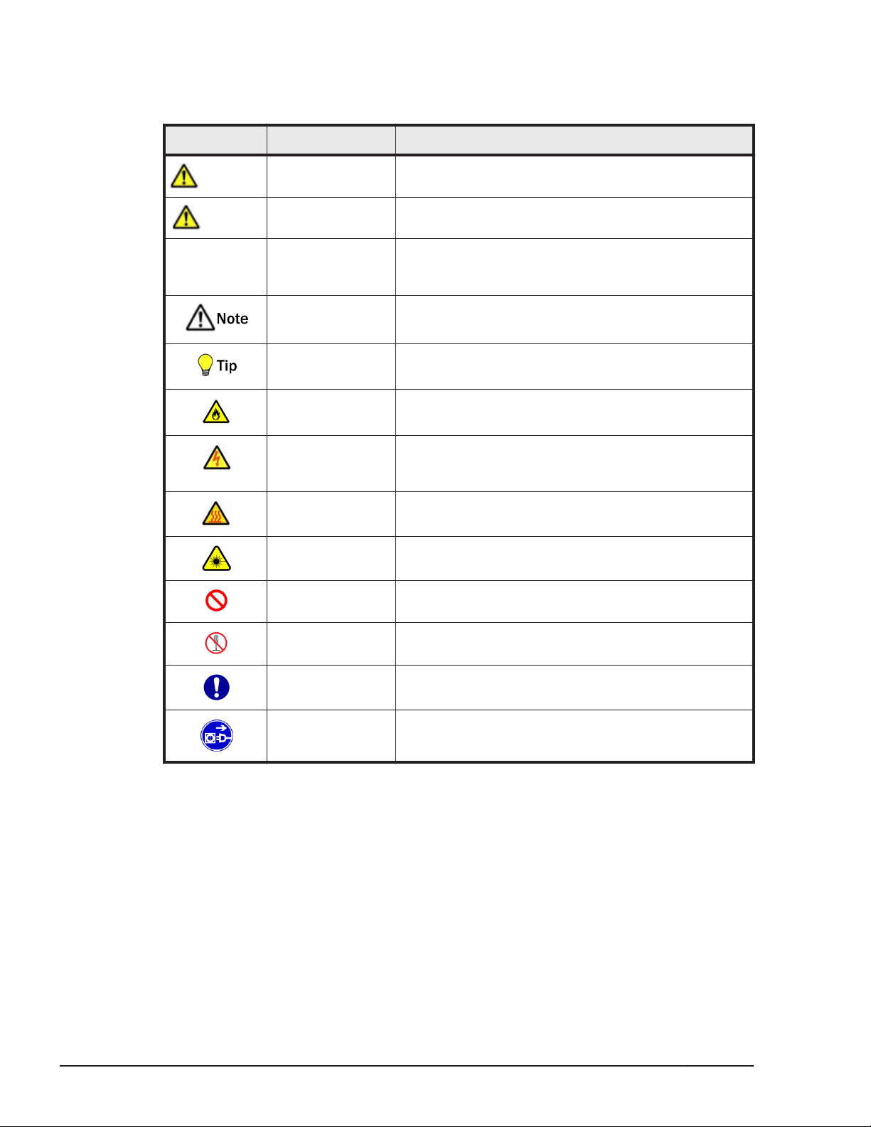
Safety Symbols
This document uses the following symbols to emphasize certain information.
Symbol Label Description
WARNING
CAUTION
NOTICE NOTICE This indicates the presence of a potential risk that
WARNING This indicates the presence of a potential risk that
might cause death or severe injury.
CAUTION This indicates the presence of a potential risk that
might cause relatively mild or moderate injury.
might cause severe damage to the equipment and/or
damage to surrounding properties.
Note This indicates notes not directly related to injury or
severe damage to equipment.
Tip This indicates advice on how to make the best use of
the equipment.
Fire Hazard This warns fire hazard. Take appropriate precautions
to prevent the risk of catching a fire.
Electric Shock
Hazard
Hot Surface Hot Surface indicates the risk of a serious burn by
Laser Hazard This warns laser hazard. Failure to take appropriate
General
Prohibition Sign
Disassembly
Prohibition Sign
General
Mandatory Sign
Unplug Power
cord
This warns electric shock hazard. Failure to take
appropriate precautions could result in serious injury
or death.
high temperature.
precautions could result in invisible laser radiation.
This indicates the general prohibition.
This indicates not to allow customer to disassemble
component.
This indicates a general action to take. Action by
following the instructions in this guide.
This indicates unplugging the power cable from the
outlet to avoid electric shock and fire.
Common precautions concerning safety
Please carefully read through, and fully understand, the following safety
instructions:
xii
• When operating the equipment, follow the instructions and procedures in
the manual.
• Be sure to follow notes, cautionary statements and advice indicated on
the equipment or in the manual.
Preface
Hitachi Compute Blade 500 Series System Service Manual
Page 13
• Referring to manuals attached to other products which you install in or
connect to the equipment, follow the instructions described in those
manuals.
Failure to follow those instructions can cause injury, fire or damage to
property including the equipment.
General safety precautions
Handling power cords
Always use the power cords shipped with the equipment, and follow the
instructions below: Failure to follow the correct handling practices lead to
damaging the power cords to expose the copper wires and to overheat
due to short-circuiting or partial disconnection, which may cause electric
shock or fire.
¢
Do not place any object on the power cords.
¢
Do not use the power cords near heat-generating appliances.
¢
Do not heat the power cords.
¢
Do not bundle the power cords.
¢
Do not subject the power cords to ultraviolet or strong visible light
continuously.
¢
Keep the power cords from contact with alkali, acid, fat and oil, or
humidity.
¢
Do not use the power cords in a high-temperature environment.
¢
Do not use the power cords above their specified rating.
¢
Do not use the power cords for other devices.
¢
Do not touch the power plug with moistened hands.
¢
Do not place any objects around the electrical outlets in order to allow
users to quickly unplug the power cords.
Poor contact and tracking
Comply with the following instructions when handling the power plug.
Otherwise, tracking or poor contact may cause overheating and a fire.
¢
Make sure that the power plug is fully and securely inserted into the
electrical outlet.
¢
Before inserting the power plug, confirm that there is no dust or a
water droplet on the plug. If any dust or water droplet is found, wipe
it off with a dry cloth and then insert it.
Preface
Hitachi Compute Blade 500 Series System Service Manual
xiii
Page 14
Requirements for power outlets
¢
Use a grounding 2-pole plug-in power outlet. Outlets of any other
types would cause an electric shock or fire.
¢
In order to prevent an electric shock, connect the outlet's grounding
electrode to a grounding terminal installed by a qualified electrician.
Without connection to the grounding terminal, an electric shock can
occur in the event of a failure in power supply modules.
Plugging and unplugging
When inserting the power plug into the electrical outlet or removing it, be
sure to hold the plug section. Do not pull the cable; it can partially break
the wire, overheat the broken part and lead to a fire.
Power supply module
Since the power supply module has a high-voltage area in it, do not open
the cover. If you do, it can result in an electric shock or equipment
failure.
Installing power supply slot cover
When removing a power supply module, do not insert your hand or tool
inside the power slot. After removing a power supply module, install a
power slot cover. Inside the power slot, some conductors are exposed. If
you touch them with your hand or tool, it may cause electric shock or
equipment failure.
Abnormal heat, smoke, abnormal noise, or abnormal smell
Should you find anything abnormal occurring, turn off the power and
unplug all the power cords of the equipment (maximum of 4) from the
electrical outlets.
Removal of the cover or bracket
Do not remove the cover or bracket. It can result in an electric shock,
burns or equipment failure.
xiv
Preface
Hitachi Compute Blade 500 Series System Service Manual
Page 15
Do not repair, remodel or disassemble
Do not attempt to repair, remodel or disassemble the equipment on your
own, except for performing expansion work in accordance with the
instructions in this manual. Work performed by unqualified persons can
lead to an electric shock, fire, or burns. Especially it is hazardous if you
touch areas inside the high-voltage power module.
High temperature at a power supply module
When a power supply module is in operation, the cover and handle get
hot. Be careful when replacing a failed module. You can get burned.
High temperature at the 10GBASE-R transceiver
The 10GBASE-R transceiver in the 10Gb LAN switch module gets hot in
operation. To remove the transceiver, therefore, allow at least
approximately 5 minutes after the power supply for the 10Gb LAN switch
module is turned off from the management module. Failure to do so can
cause you to get burned.
Adding and replacing parts
The cover and internal parts are hot immediately after the power is
turned off. You must wait for about 30 minutes before adding or removing
internal parts unless otherwise specified in this manual. If not, the hot
equipment causes you to get burned.
Laser beam
¢
On this product, a Class 1 laser product is installed. Do not look
directly at the laser beam. Do not look at the laser beam using an
optical instrument.
¢
Under the laser module cover, a laser beam is being emitted. Do not
remove the cover of an unused board.
Contact with metal edges
When moving the equipment or adding parts, take care not to hurt
yourself on the metal or plastic edges. You can wear cotton gloves to
protect your hands.
Preface
Hitachi Compute Blade 500 Series System Service Manual
xv
Page 16
Installing the equipment in a rack
To install or remove the system equipment in or from the rack cabinet,
always get help from at least one other person or use tools. If the system
equipment has to be installed on 31U and above of the rack cabinet or it
is already installed there, call for maintenance personnel instead of
attempting to install or remove it. Defective installation may cause the
system equipment to fall, resulting in injury or equipment failure.
Requirements for the product
Install the product on a fixed rack. Do not lean against the product or
stand on it. Do not install the product in a place with weak floors and
walls.
Do not subject the product to excessive vibration. That can drop and fall
the product, leading to failure.
Using a rack cabinet
When using a rack cabinet, do not place anything on the system unit
mounted on the cabinet and do not use the top of the system unit
mounted on the cabinet as a workbench. A heavy object placed on top of
the system unit on the cabinet may fall, resulting in injury.
xvi
Locking the rail into place
Be sure to pull out the equipment until it locks into place. If not, the
equipment may move unexpectedly, which causes you to get injured such
as your finger caught in the gap.
Improper battery type
Risk of Explosion if Battery is replaced by an Incorrect Type. Dispose of
Used Batteries According to the Instructions.
Handling of batteries
Since maintenance personnel should change batteries, do not change
them yourself. Follow the instructions described below. Inappropriate
Preface
Hitachi Compute Blade 500 Series System Service Manual
Page 17
handling can result in injury because the battery can overheat, burst, and
catch fire.
¢
Do not put the battery on charge.
¢
Do not short out the battery.
¢
Do not disassemble the battery.
Storing batteries
When storing batteries, apply adhesive tape on the terminals for
insulation. If the batteries are stored without insulation, the terminals can
contact each other to cause a short-circuit and overheat or burst, leading
to injury or fire.
Precautions against damage to equipment
Insertion of foreign objects into the equipment
Do not allow clips, pins or any other metal items or flammable items to
enter the equipment through a vent or by any other means. Continuing to
operate the equipment with foreign objects could cause failure.
Impact from falling
Do not fall the equipment or hit it against another object. It can cause
internal deformation and deterioration. Operating the equipment under
such defective conditions can cause failure.
Vent
A vent is used for preventing rise in temperature inside the equipment.
Do not block the vent by placing or leaning an object. If you do, the
temperature rises, which can cause failure. Check and clean ventilation
holes periodically to keep the dust from gathering on them.
Contact with connection terminals
Do not touch connection terminals, such as a connector with your hand or
any metal item. Do not insert any objects such as wire into them. Do not
place the equipment in a place with metal pieces. If you do, a short circuit
can be developed, causing equipment failure.
Preface
Hitachi Compute Blade 500 Series System Service Manual
xvii
Page 18

Moving between two locations with a temperature differential
When you move the equipment from one location to another, a significant
temperature gap between the two locations may cause condensation on
the surface or inside the equipment. Operating the equipment with
condensation inside can cause a failure in equipment. Leave the
equipment at the new location for several hours until the equipment
temperature conforms to that of the new environment before you start
using it. When you move the equipment from an environment with
temperature 5°C to that with 25°C, for example, leave it for about two
hours.
Adding and connecting to peripheral devices
Use only peripheral devices which are explicitly listed as supported in the
manual, and always follow the instructions in the manual. Using devices
other than those mentioned above would cause a failure in peripheral
devices and equipment due to the difference in connection specifications.
Radio interference
When you install the equipment next to another electronic device, the
radio waves may interfere with each other. In particular, a television set
or a radio in the vicinity may make a noise.
xviii
Magnetism generator
Do not place a device that generates strong magnetism, such as a
magnet or a speaker, near the equipment. Doing so can cause a system
unit failure.
Handling hard disks
A hard disk is a precision instrument. Handle it carefully when you use it.
Inappropriate handling could result in hard disk failure.
Faulty disk
Preface
Hitachi Compute Blade 500 Series System Service Manual
Page 19

If you attempt to replace faulty disks using an incorrect procedure or
faulty alternative disk, data on the disk can be corrupted. Before
replacing the disk, back up the data.
Aluminum electrolytic capacitors
An aluminum electrolytic capacitor has a limited service life. Do not use it
past its service life. Otherwise, leakage or depletion of the electrolyte may
cause smoke or electric shock. To avoid such hazardous situations,
replace limited-life parts once they are past their designated service life.
Distribution board
Install a distribution board close to an entrance / exit to protect the
devices in your computer system and to serve as an emergency power
breaker.
Signal cables
¢
Route cables not to trip over them. Tripping over cables could cause
injury or failure of devices connected to the equipment, and also could
cause loss of valuable data.
¢
Do not place heavy items on the cables. Avoid routing cables close to
a thermal appliance. If you do, it could cause damage to cable
sheaths, resulting in failure of the connected devices.
Before turning off the power
¢
Follow the prescribed procedure for power operation. Power input or
output not according to the prescribed procedure may cause problems
on the system equipment.
¢
Before turning off the power, confirm that all devices connected to the
equipment stop. Turning off the power during operation of the
equipment may cause equipment failure or data loss.
¢
When you are using an OS which requires the shut down procedure,
be sure to finish the shut down procedure before turning off the
power. Otherwise, data may be lost.
Rack Mount Safety Consideration
Preface
Hitachi Compute Blade 500 Series System Service Manual
xix
Page 20
¢
Elevated Ambient Temperature
If installed in a closed or multi-unit rack assembly, the operating
ambient temperature of the rack environment may be greater than
room ambient. Use care not to exceed the rated maximum ambient
temperature of the unit.
¢
Reduced Air Flow
Installation of the equipment in a rack should be such that the
amount of airflow required for safe operation of the equipment is not
compromised.
¢
Mechanical Loading
Mounting of the equipment in the rack should be such that a
hazardous condition is not achieved due to uneven mechanical
loading.
¢
Circuit Overloading
Consideration should be given to the connection of the equipment to
the supply circuit and the effect that overloading of the circuits might
have on over current protection and supply wiring. Appropriate
consideration of equipment nameplate ratings should be used when
addressing this concern.
¢
Reliable Earthing
Reliable earthing of rack-mounted equipment should be maintained.
Pay particular attention to supply connections other than direct
connections to the branch circuit (e.g. use of power strips)."
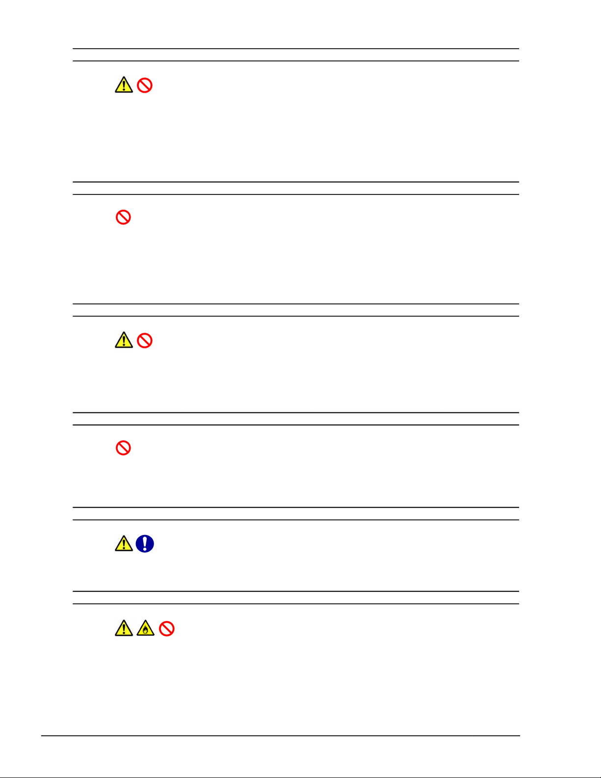
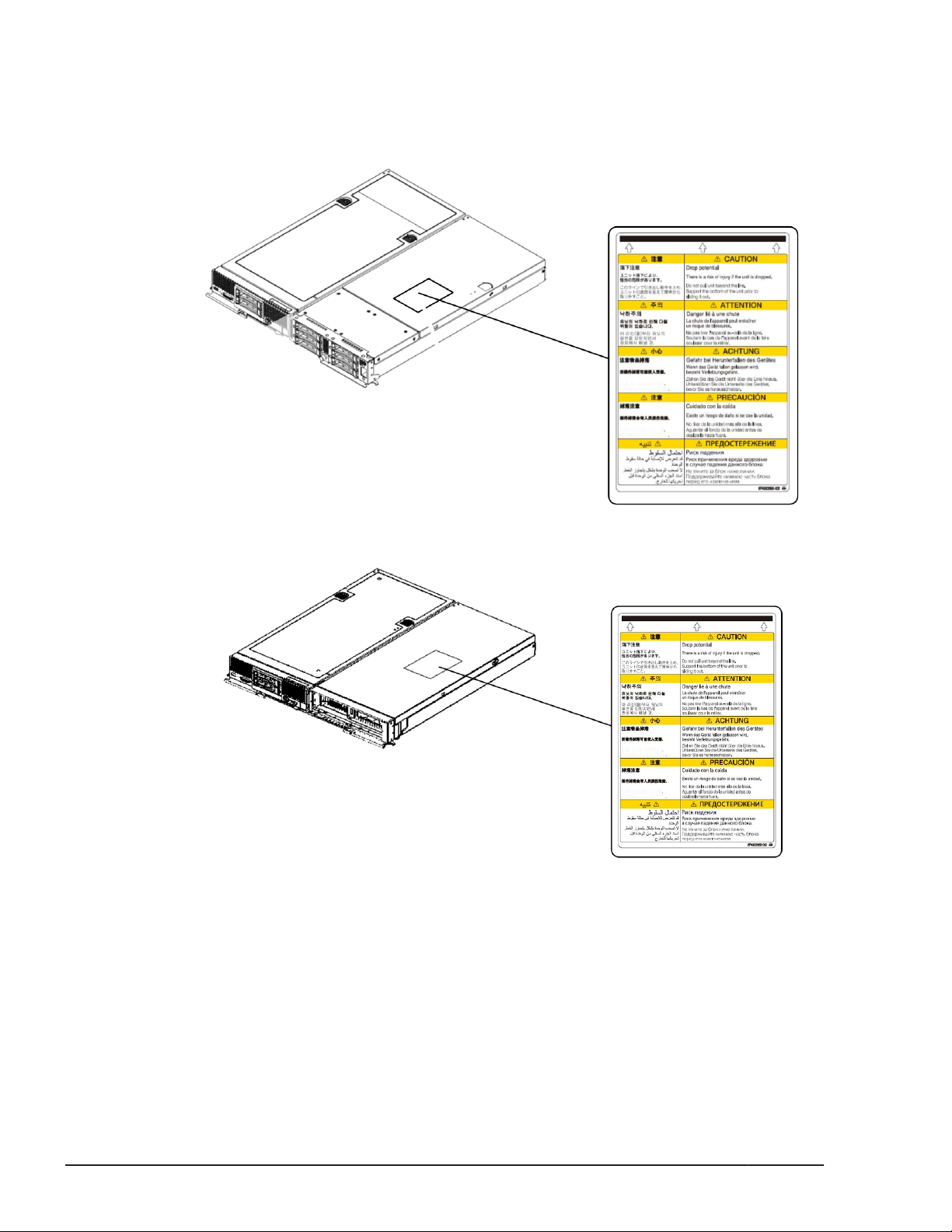
Safety and warning labels
Server chassis
The location and content of the warning and safety labels on the server
chassis are shown here.
xx
Preface
Hitachi Compute Blade 500 Series System Service Manual
Page 21
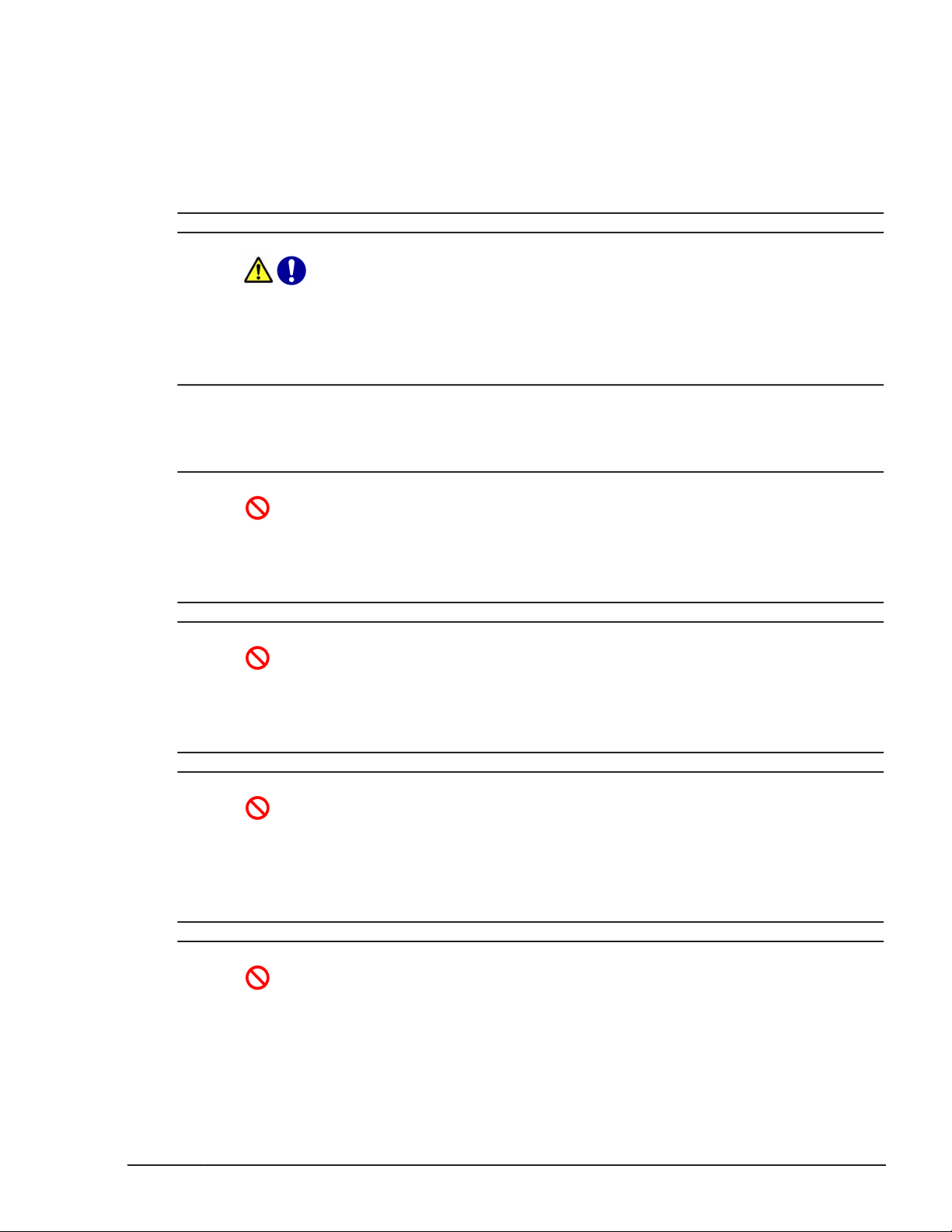
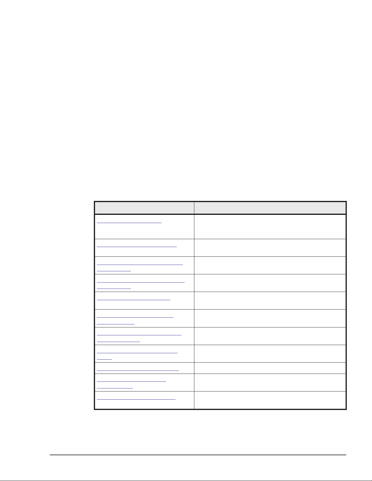
Server blade
The following figures show the location and content of the safety and warning
label on the server blade.
Half-wide server blade / Full-wide server blade
Preface
Hitachi Compute Blade 500 Series System Service Manual
xxi
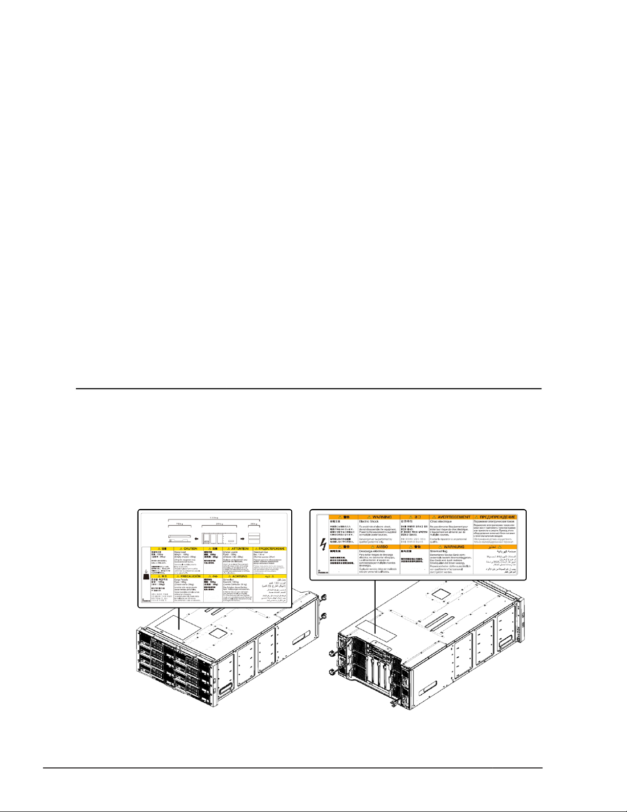
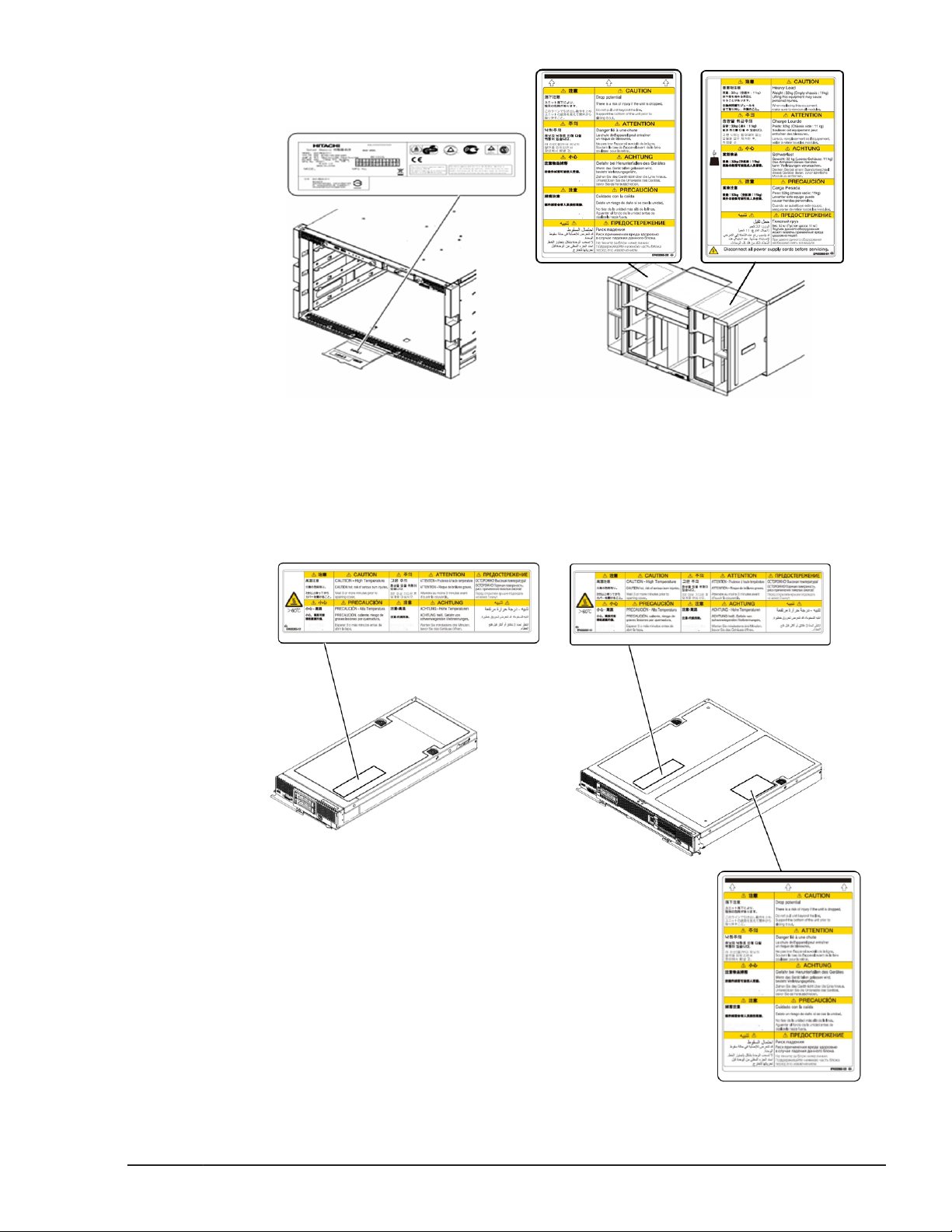
Page 22
The following shows the location and content of the safety and warning label
on the expansion blade.
Storage expansion blade
PCI expansion blade
Intended Audience
This document is intended for the personnel who are involved in planning,
managing, and performing the tasks to prepare your site for Compute Blade
installation and to install the same.
xxii
This document assumes the following:
• The reader has a background in hardware installation of computer
systems.
Preface
Hitachi Compute Blade 500 Series System Service Manual
Page 23
• The reader is familiar with the location where the Compute Blade will be
installed, including knowledge of physical characteristics, power systems
and specifications, and environmental specifications.
Product Version
This document revision applies to CB 520X B3.
Release notes
Read the release notes before installing and using this product. They may
contain requirements or restrictions that are not fully described in this
document or updates or corrections to this document.
Document Organization
The table below provides an overview of the contents and organization of this
document. Click the chapter title in the left column to go to that chapter. The
first page of each chapter provides links to the sections in that chapter.
Chapter Description
Chapter 1, Introduction Describes the overview of user maintenance and
troubleshooting tasks for the Hitachi Compute Blade
500 Series.
Chapter 2, Replaceable parts Describes the replaceable parts for Hitachi Compute
Blade 500 Series.
Chapter 3, Basic knowledge for
replacement
Chapter 4, Common process for
replacement
Chapter 5, Replacing parts Describes how to remove and install parts on the
Chapter 6, Identifying RAID
rebuild status
Chapter 7, Configuring Emulex
mezzanine card
Chapter 8, Diagnosing server
blade
Chapter 9, Updating firmware Describes how to update firmware.
Chapter 10, Change LOM
configuration
Describes how to verify a failed part and how to
order a failed part.
Describes the common processes before replacing
part.
Hitachi Compute Blade 500 Series.
Describes how to confirm the rebuild progress after
HDD replacement.
Describes how to configure Emulex mezzanine card
after replacement.
Describes how to diagnosing the server blade.
Describes how to change LOM configuration.
Chapter 11, Troubleshooting Describes how to troubleshoot the Hitachi Compute
Blade 500 Series.
Preface
Hitachi Compute Blade 500 Series System Service Manual
xxiii
Page 24
Document conventions
This term "Compute Blade" refers to all the models of the Compute Blade,
unless otherwise noted.
The Hitachi Virtualization Manager (HVM) name has been changed to Hitachi
logical partitioning manager (LPAR manager, or LP). If you are using HVM
based logical partitioning feature, substitute references to Hitachi logical
partitioning manager (LPAR manager, or LP) with HVM.
This document uses the following typographic conventions:
Convention Description
Regular text bold In text: keyboard key, parameter name, property name, hardware
Italic Variable, emphasis, reference to document title, called-out term
labels, hardware button, hardware switch
In a procedure: user interface item
Screen text
< > (angle brackets) Variable (used when italic is not enough to identify variable)
[ ] (square brackets) Optional value
{ } (braces) Required or expected value
| (vertical bar) Choice between two or more options or arguments.
Command name and option, drive name, file name, folder name,
directory name, code, file content, system and application output,
user input
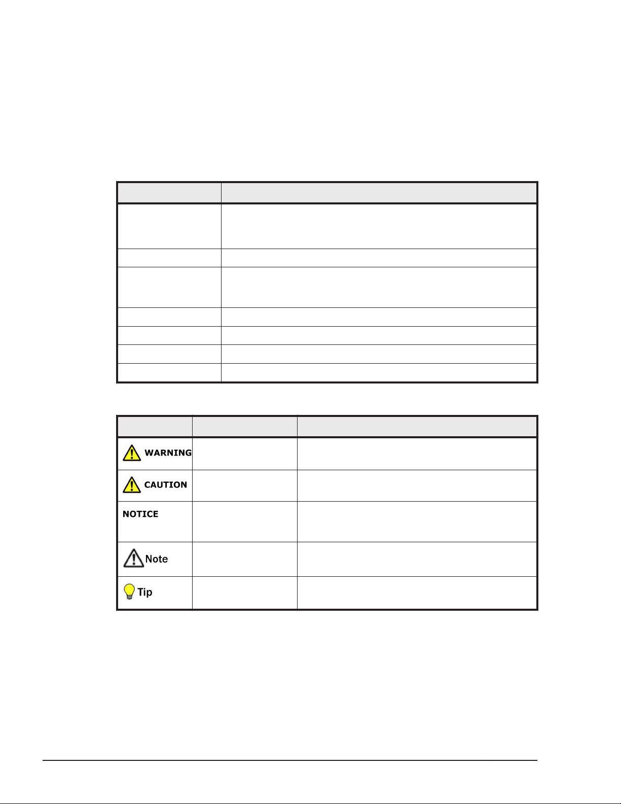
This document uses the following icons to draw attention to information:
Icon Meaning Description
WARNING This indicates the presence of a potential risk that
might cause death or severe injury.
CAUTION This indicates the presence of a potential risk that
might cause relatively mild or moderate injury.
NOTICE This indicates the presence of a potential risk that
might cause severe damage to the equipment
and/or damage to surrounding properties.
Note This indicates notes not directly related to injury
or severe damage to equipment.
Getting help
If you purchased this product from an authorized HDS reseller, contact that
reseller for support. For the name of your nearest HDS authorized reseller,
refer to the HDS support web site for locations and contact information. To
xxiv
Tip This indicates advice on how to make the best use
of the equipment.
Preface
Hitachi Compute Blade 500 Series System Service Manual
Page 25

contact the Hitachi Data Systems Support Center, please visit the HDS
website for current telephone numbers and other contact information:
http://support.hds.com.
Before calling the Hitachi Data Systems Support Center, please provide as
much information about the problem as possible, including:
• The circumstances surrounding the error or failure.
• The exact content of any error message(s) displayed on the host
Comments
Please send us your comments on this document: doc.comments@hds.com.
Include the document title, number, and revision, and refer to specific
sections and paragraphs whenever possible. All comments become the
property of Hitachi Data Systems Corporation.
Thank you!
system(s).
Preface
Hitachi Compute Blade 500 Series System Service Manual
xxv
Page 26

xxvi
Preface
Hitachi Compute Blade 500 Series System Service Manual
Page 27

1
Introduction
This chapter provides an overview of user maintenance and troubleshooting
tasks for the Hitachi Compute Blade system. This chapter covers the following
key topics:
User replacement guidelines
□
User maintenance tasks
□
When a failure occurs
□
System overview
□
Server blade
□
Location
□
Hot-swappable components
□
Indicators and connectors
□
Color code for maintenance
□
Introduction
Hitachi Compute Blade 500 Series System Service Manual
1-1
Page 28
User replacement guidelines
The Hitachi Compute Blade system is designed with many customer
replaceable units (CRUs) to allow for greater flexibility in performing defective
parts replacement. However, you should consult with Hitachi Data Systems
Support about the failed parts before replacement. After consultation, Hitachi
Data Systems Support will ship the spare part directly to you for
replacement.
Each module contains several LEDs that light when certain problems occur,
making it easy for users to quickly find the source of these problems. The
LEDs are described in this chapter. In addition, the web console generates
system messages that identify the failed parts and notifies users the
procedures that should be performed to keep the performance. The web
console can be configured to send E-mail messages to specified email
addresses, notifying users of failed parts or reminding them of scheduled
tasks. You can order and install the parts or perform the procedures.
User maintenance tasks
The maintenance tasks described in this manual follow the Hitachi Data
Systems Customer Support program.
• The Hitachi Data Systems self-service program allows users to perform
allowable installation and configuration tasks and maintenance tasks on
the Hitachi Compute Blade System.
1-2
Hitachi Compute Blade 500 Series System Service Manual
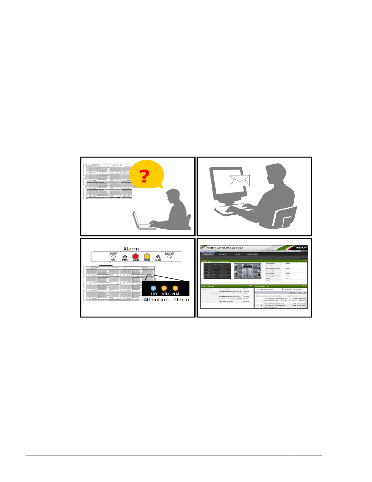
Figure 1-1 Identifying a failed part
Introduction
Page 29
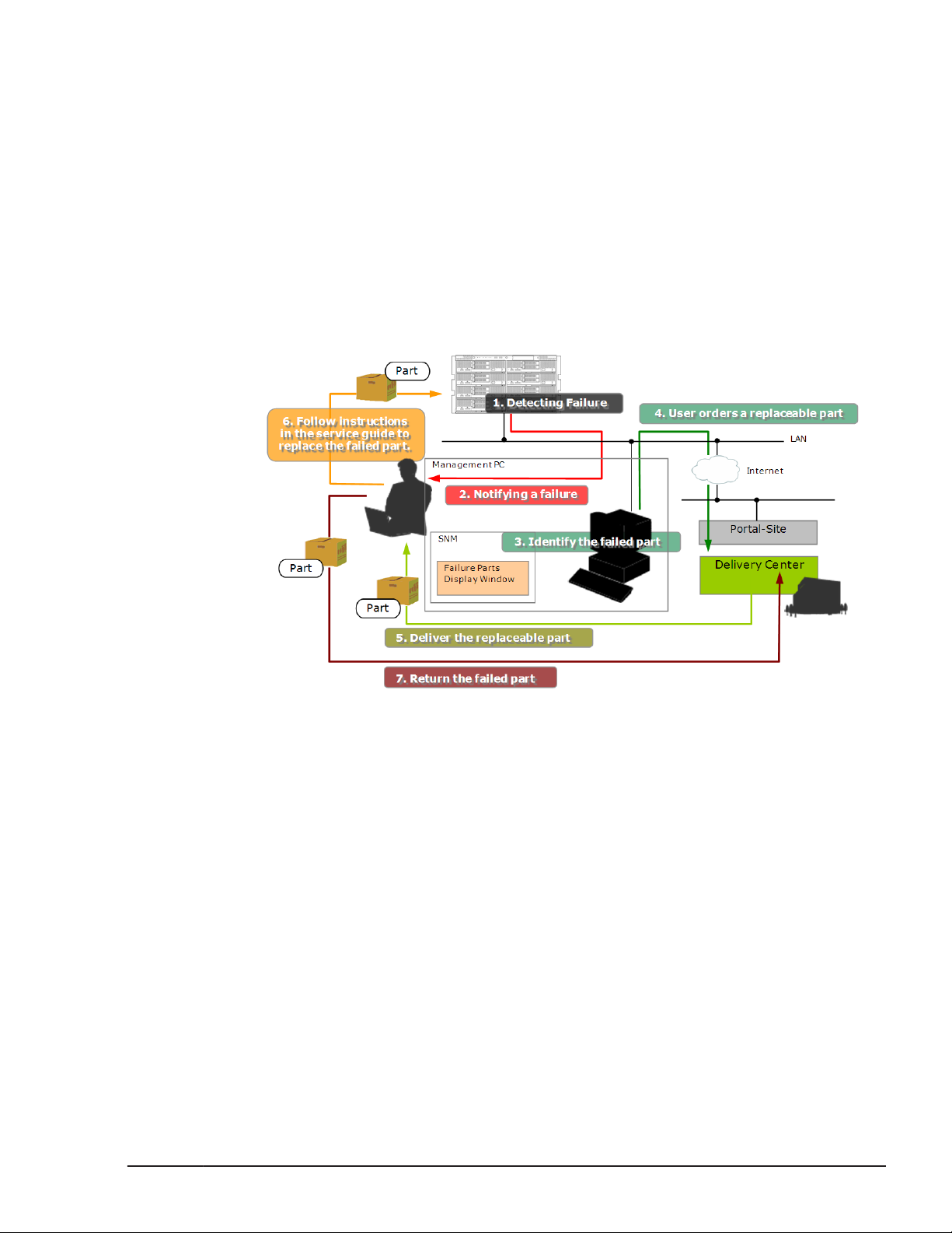
When a failure occurs
The following is an overview of the maintenance tasks you can perform when
a failure occurs on your system.
1. Failure detection in the subsystem. (1)
2. Failure notification (E-mail, SNMP, LED). (2)
3. Determining the failed parts using the web console. (3)
4. Contacting Hitachi Data Systems Technical Support and ordering the
parts. (4)
5. Replacing the parts after the spare parts arrive and checking the recovery
from the failure. (5), (6)
6. Return the replaced parts (7).
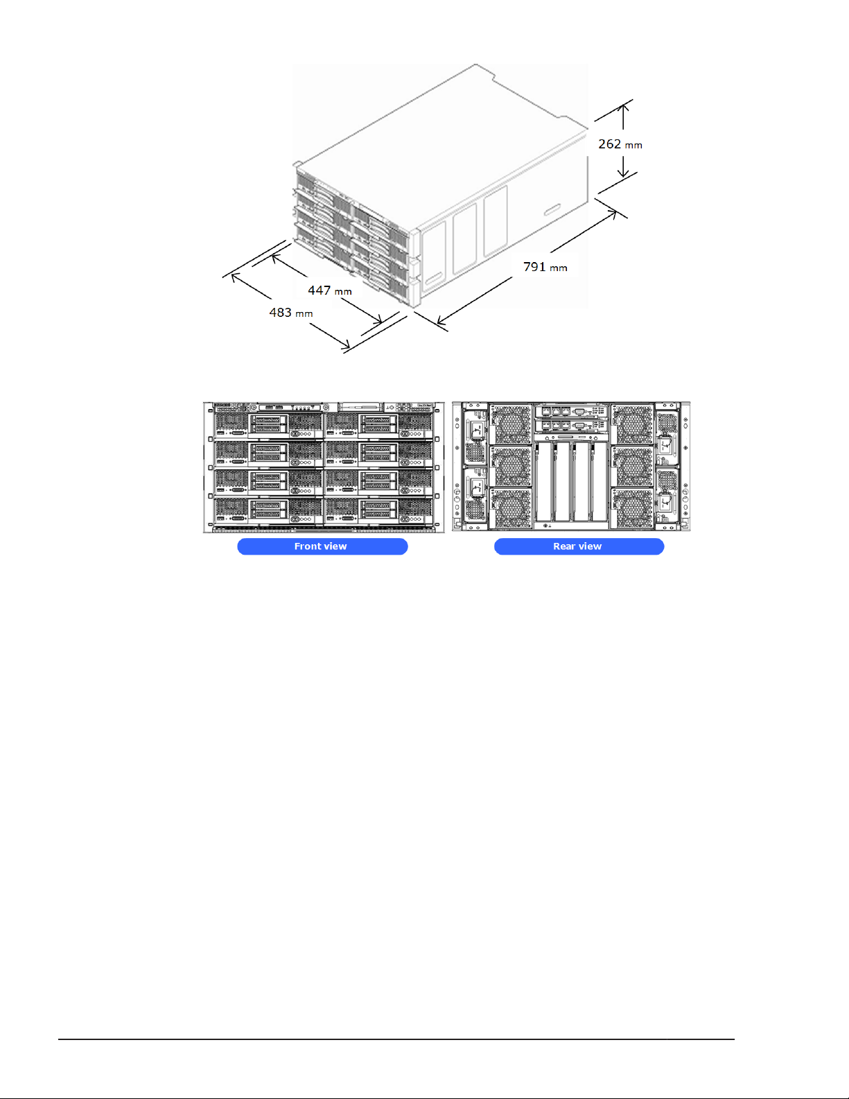
System overview
The Hitachi Compute Blade 500 series system can contain up to eight server
blades and four switch modules. Compared with a 1U server chassis that
contains a rack mount network switch and a FC switch, the 6U height Hitachi
Compute Blade 500 server chassis offers improved features such as less
space, fewer cables, and decreased weight. The system has the ability for
replacing existing PC server systems, consolidating servers, and for operating
servers in a data center. Suitable switch modules can be selected from the
available interfaces according to the customer demands. The management
modules, switch modules, power supply modules, and cooling fan modules
provide a redundant configuration. The system can continue to operate
because of the redundant configuration even if one of the modules
experiences a failure.
Hitachi Compute Blade 500 Series System Service Manual
Figure 1-2 User maintenance process
Introduction
1-3
Page 30
Server blade
The CB 500 server blade offers the following key features:
• High-performance Intel multi-core processor with QPI technology for
• High operability through the high- reliability, availability, and
• High density, high performance optimized for enterprise data center,
Figure 1-3 Server chassis overview
Figure 1-4 Front/rear view of server chassis
high-throughput and low-latency.
serviceability features of processor, memory, and HDD, such as memory
scrubbing (self-error-correcting), memory mirroring function (memory
duplication), and integrated Hardware RAID 1.
virtualization, high-speed computing, and flexible IO capability.
1-4
A server blade contains processors, memory, HDDs, and other components,
and is available in either one of four form factors: the "Half-wide server
blade", "Full-wide server blade", "Storage expansion blade" for HDD, and "PCI
expansion blade" for PCIe card, expanded with a "Half-wide blade".
Introduction
Hitachi Compute Blade 500 Series System Service Manual
Page 31

Table 1-1 Form factor and model names
Form factor Model Name
Half-wide blade CB 520A A1 (Standard
model)
CB 520H
A1/B1/B2/B3 /
B4(High-end model)
Full-wide blade CB 540A A1/B1 4 435.3 x 492.7 x
CB 520X B1/B2/B3 2
Expansion blade Storage expansion
blade
PCI expansion blade 0 215.4 x 492.7 x
Number of
processors
2 215.4 x 492.7 x
0 435.3 x 492.7 x
(W x D x H: mm)
51.1
55.5
55.5
55.5
Size
Available
Yes
Yes
Yes
Yes
Figure 1-5 Server blades
Introduction
Hitachi Compute Blade 500 Series System Service Manual
1-5
Page 32

Location
Server blade numbering
Symbol Component Symbol Component
0 Server blade #0 4 Server blade #4
Figure 1-6 Blade location in server chassis
Table 1-2 Location of installable blades
1 Server blade #1 5 Server blade #5
2 Server blade #2 6 Server blade #6
3 Server blade #3 7 Server blade #7
Management module numbering
Figure 1-7 Location in server chassis
1-6
Table 1-3 Location of installable components
Symbol Component
0 Management module #0
Introduction
Hitachi Compute Blade 500 Series System Service Manual
Page 33

Symbol Component
1 Management module #1
Switch module numbering
Table 1-4 Location of installable components
Figure 1-8 Location in server chassis
Symbol Component Symbol Component
0 Switch module #0 2 Switch module #2
1 Switch module #1 3 Switch module #3
Power supply module numbering
Figure 1-9 Location in server chassis
Table 1-5 Location of installable components
Symbol Component Symbol Component
0 Power supply module #0 2 Power supply module #2
Introduction
Hitachi Compute Blade 500 Series System Service Manual
1-7
Page 34

Symbol Component Symbol Component
1 Power supply module #1 3 Power supply module #3
Cooling fan module numbering
Figure 1-10 Location in server chassis
Table 1-6 Location of installable components
Symbol Component Symbol Component
0 Fan module #0 3 Fan module #3
1 Fan module #1 4 Fan module #4
2 Fan module #2 5 Fan module #5
Disk drive numbering: CB 520A A1, CB 520H A1/B1/B2/B3/B4
The disk drive numbering in a server blade is #0 to #1 from the bottom to
top, as viewed from the front of the server blade. The same numbering
applies to all server blades in the server chassis.
1-8
Figure 1-11 Disk drive location
Introduction
Hitachi Compute Blade 500 Series System Service Manual
Page 35

Table 1-7 Location of installable components
Symbol Component
0 HDD #0
1 HDD #1
Disk drive numbering: CB 540A A1/B1
The disk drive numbering in a server blade is #0 to #1/2 from the left to
right, as viewed from the front of the server blade. The same numbering
applies to all server blades in the server chassis.
Figure 1-12 Disk drive location
Table 1-8 Location of installable components
Symbol Component
0 HDD #0
1 HDD #1 (Using the RAID Mezzanine or Combo Mezzanine) /
HDD #2 (Using the Onboard RAID)
Disk drive numbering: CB 520X B1/B2/B3
The disk drive numbering in a server blade is #0 to #2 from the left to right,
as viewed from the front of the server blade. The same numbering applies to
all server blades in the server chassis.
Introduction
Hitachi Compute Blade 500 Series System Service Manual
1-9
Page 36

Figure 1-13 Disk drive location
Table 1-9 Location of installable components
Symbol Component
0 HDD #0
2 HDD #2
Disk drive numbering: Storage expansion blade
The disk drive numbering in a storage expansion blade is #0 to #6 from the
bottom to top, as viewed from the front of the storage expansion blade.
Numbering applies to all blades in the server chassis.
Figure 1-14 Disk drive location
1-10
Table 1-10 Location of installable components
Symbol Component Symbol Component
0 HDD #0 4 HDD #4
1 HDD #1 5 HDD #5
2 HDD #2 6 HDD #6
Introduction
Hitachi Compute Blade 500 Series System Service Manual
Page 37

Processor numbering: CB 520A A1
The processor numbering in a server blade is #1 to #2 from the rear to front,
as viewed from the front of the server blade.
Figure 1-15 Processor location
Table 1-11 Location of processors
Symbol Component
1 CPU #1
2 CPU #2
Processor numbering: CB 520H A1/B1/B2/B3/B4
The processor numbering in a server blade is #1 to #2 from the rear to front,
as viewed from the front of the server blade.
Figure 1-16 Processor location
Table 1-12 Location of processors
Symbol Component
1 CPU #1
Introduction
Hitachi Compute Blade 500 Series System Service Manual
1-11
Page 38

Symbol Component
2 CPU #2
Processor numbering: CB 540A A1/B1
The processor numbering in a server blade is #1 to #4 from the rear to front,
as viewed from the front of the server blade.
Figure 1-17 Processor location
Table 1-13 Location of processors
Symbol Component Symbol Component
1 CPU #1 3 CPU #3
2 CPU #2 4 CPU #4
Processor numbering: CB 520X B1/B2/B3
The processor numbering in a server blade is #1 to #2 from the left to right,
as viewed from the front of the server blade.
1-12
Figure 1-18 Processor location
Introduction
Hitachi Compute Blade 500 Series System Service Manual
Page 39

Table 1-14 Location of processors
Symbol Component
1 CPU #1
2 CPU #2
DIMM numbering: CB 520A A1
The DIMM numbering in CB 520A A1 is #1 to #12 shown as following figure.
Figure 1-19 DIMM in CB 520A A1
Table 1-15 Location of DIMMs in CB 520A A1
Symbol Component Symbol Component
1 DIMM #1 7 DIMM #7
2 DIMM #2 8 DIMM #8
3 DIMM #3 9 DIMM #9
4 DIMM #4 10 DIMM #10
5 DIMM #5 11 DIMM #11
6 DIMM #6 12 DIMM #12
DIMM numbering: CB 520H A1/B1/B2/B3/B4
The DIMM numbering in CB 520H A1/B1/B2/B3/B4 is #1 to #24 shown as
following figure.
Introduction
Hitachi Compute Blade 500 Series System Service Manual
1-13
Page 40

Figure 1-20 DIMM in CB 520H A1/B1/B2/B3/B4
Table 1-16 Location of DIMMs in CB 520H A1/B1/B2/B3/B4
Symbol Component Symbol Component
1 DIMM #1 13 DIMM #13
2 DIMM #2 14 DIMM #14
3 DIMM #3 15 DIMM #15
4 DIMM #4 16 DIMM #16
5 DIMM #5 17 DIMM #17
6 DIMM #6 18 DIMM #18
7 DIMM #7 19 DIMM #19
8 DIMM #8 20 DIMM #20
9 DIMM #9 21 DIMM #21
10 DIMM #10 22 DIMM #22
11 DIMM #11 23 DIMM #23
12 DIMM #12 24 DIMM #24
DIMM numbering: CB 540A A1/B1
The DIMM numbering in CB 540A A1/B1 is #1 to #48 shown as following
figure.
1-14
Hitachi Compute Blade 500 Series System Service Manual
Introduction
Page 41

Figure 1-21 DIMM in CB 540A A1/B1
Table 1-17 Location of DIMMs in CB 540A A1/B1
Symbol Component Symbol Component Symbol Component Symbol Component
1 DIMM #1 13 DIMM #13 25 DIMM #25 37 DIMM #37
2 DIMM #2 14 DIMM #14 26 DIMM #26 38 DIMM #38
3 DIMM #3 15 DIMM #15 27 DIMM #27 39 DIMM #39
4 DIMM #4 16 DIMM #16 28 DIMM #28 40 DIMM #40
5 DIMM #5 17 DIMM #17 29 DIMM #29 41 DIMM #41
6 DIMM #6 18 DIMM #18 30 DIMM #30 42 DIMM #42
7 DIMM #7 19 DIMM #19 31 DIMM #31 43 DIMM #43
8 DIMM #8 20 DIMM #20 32 DIMM #32 44 DIMM #44
9 DIMM #9 21 DIMM #21 33 DIMM #33 45 DIMM #45
10 DIMM #10 22 DIMM #22 34 DIMM #34 46 DIMM #46
11 DIMM #11 23 DIMM #23 35 DIMM #35 47 DIMM #47
12 DIMM #12 24 DIMM #24 36 DIMM #36 48 DIMM #48
Introduction
Hitachi Compute Blade 500 Series System Service Manual
1-15
Page 42

DIMM numbering: CB 520X B1/B2/B3
The DIMM numbering in CB 520X B1/B2/B3 is #1 to #48 shown as following
figure.
Figure 1-22 DIMM in CB 520X B1/B2/B3
Table 1-18 Location of DIMMs in CB 520X B1/B2/B3
Symbol Component Symbol Component Symbol Component Symbol Component
1 DIMM #1 13 DIMM #13 25 DIMM #25 37 DIMM #37
2 DIMM #2 14 DIMM #14 26 DIMM #26 38 DIMM #38
3 DIMM #3 15 DIMM #15 27 DIMM #27 39 DIMM #39
4 DIMM #4 16 DIMM #16 28 DIMM #28 40 DIMM #40
5 DIMM #5 17 DIMM #17 29 DIMM #29 41 DIMM #41
6 DIMM #6 18 DIMM #18 30 DIMM #30 42 DIMM #42
7 DIMM #7 19 DIMM #19 31 DIMM #31 43 DIMM #43
8 DIMM #8 20 DIMM #20 32 DIMM #32 44 DIMM #44
9 DIMM #9 21 DIMM #21 33 DIMM #33 45 DIMM #45
10 DIMM #10 22 DIMM #22 34 DIMM #34 46 DIMM #46
1-16
Introduction
Hitachi Compute Blade 500 Series System Service Manual
Page 43

Symbol Component Symbol Component Symbol Component Symbol Component
11 DIMM #11 23 DIMM #23 35 DIMM #35 47 DIMM #47
12 DIMM #12 24 DIMM #24 36 DIMM #36 48 DIMM #48
Mezzanine card numbering: CB 520A A1
Figure 1-23 Mezzanine card in server blade
Table 1-19 Location of installable components
Symbol Component
1 Mezzanine #1
2 Mezzanine #2
Introduction
Hitachi Compute Blade 500 Series System Service Manual
1-17
Page 44

Mezzanine card numbering: CB 520H A1/B1/B2/B3/B4
Figure 1-24 Mezzanine card in server blade without LOM (CB 520H A1)
Table 1-20 Location of installable components
Symbol Component
1 Mezzanine #1
2 Mezzanine #2
Figure 1-25 Mezzanine card in server blade with LOM (CB 520H
B1/B2/B3/B4)
Table 1-21 Location of installable components
1-18
Symbol Component
1 LOM pass through connector
2 Mezzanine #2
Introduction
Hitachi Compute Blade 500 Series System Service Manual
Page 45

Mezzanine card numbering: CB 540A A1/B1
Figure 1-26 Mezzanine card in server blade without LOM (CB 540A A1)
Table 1-22 Location of installable components
Symbol Component Symbol Component
1 Mezzanine #1 3 Mezzanine #3
2 Mezzanine #2 4 Mezzanine #4
Figure 1-27 Mezzanine card in server blade with LOM (CB 540A B1)
Introduction
Hitachi Compute Blade 500 Series System Service Manual
1-19
Page 46

Table 1-23 Location of installable components
Symbol Component Symbol Component
1 LOM pass through connector 3 LOM pass through connector
2 Mezzanine #2 4 Mezzanine #4
Mezzanine card numbering: CB 520X B1/B2/B3
Figure 1-28 Mezzanine card in server blade with LOM (CB 520X B1/B2/B3)
Table 1-24 Location of installable components
Symbol Component Symbol Component
1 LOM pass through connector 3 LOM pass through connector
2 Mezzanine #2 4 Mezzanine #4
1-20
Introduction
Hitachi Compute Blade 500 Series System Service Manual
Page 47

Mezzanine card numbering: Storage expansion blade
Figure 1-29 Mezzanine card in server (storage expansion blade)
Table 1-25 Location of installable components
Symbol Component
1 Mezzanine #1
2 Mezzanine #2 (Pass through mezzanine)
3 Mezzanine #4
Figure 1-30 PCI card in storage expansion blade
Table 1-26 Location of installable components
Symbol Component
1 PCI card #0
Introduction
Hitachi Compute Blade 500 Series System Service Manual
1-21
Page 48

Symbol Component
2 PCI card #1
Mezzanine card numbering: PCI expansion blade
Figure 1-31 Mezzanine card in server/PCI expansion blade
Table 1-27 Location of installable components
Symbol Component
1 Mezzanine #1
2 Mezzanine #2 (PCI blade connection kit F/H)
3 Mezzanine #0 (PCI blade connection kit L/P)
4 Mezzanine #4
1-22
Introduction
Hitachi Compute Blade 500 Series System Service Manual
Page 49

Figure 1-32 PCI card in PCI expansion blade
Table 1-28 Location of installable components
Symbol Component Symbol Component
1 PCI card #0 4 PCI card #3
2 PCI card #1 5 PCI card #4
3 PCI card #2 6 PCI card #5
Hot-swappable components
All installed modules or units are designed to be hot-swappable from the front
or rear of the chassis. The following shows the hot-swap direction for each
module or unit.
Introduction
Hitachi Compute Blade 500 Series System Service Manual
1-23
Page 50

Figure 1-33 Hot-swappable components
Indicators and connectors
This section describes the switches, connectors, and LEDs on the Hitachi
Compute Blade 500 series system.
1-24
Introduction
Hitachi Compute Blade 500 Series System Service Manual
Page 51

Server chassis
No. Name State Description
Figure 1-34 Front panel in server chassis
Table 1-29 LEDs, switches, and connectors on front panel
1 USB port 0
(USB0)
2 USB port 1
(USB1)
3 Forced power off
switch (POFF)
4 Power LED
(PWR)
5 Alarm LED
(ALM)
- • Shared USB ports in the chassis
• Supported device:
-
- Press and hold it for four seconds or more, then the
Green-On Main powers of any server blades are turned on.
Green-
Blink
Amber-On All server blades are under stand-by condition
Amber-
Blink
Off Power is not supplied to the server chassis.
Red –On A serious error has occurred in the server chassis.
- LCD touch console
- USB Memory and USB DVD-ROM drive
main power is turned off.
The system is shutting down by the management
module. Keep blink until all main powers are turned
off in all server blades.
Initializing process below;
- The management module is booting.
- The server blade is initializing
- The switch module is booting.
Please contact Hitachi Data Systems Technical
Support. See the Getting Help section in the Preface
of this manual.
6 Warning LED
(WRN)
7 Identify LED
(LID)
Hitachi Compute Blade 500 Series System Service Manual
Off Normal operation
Amber-On Non-serious error has occurred. The server chassis
can continue to operate, but any modules have
warning or error status. See the Getting Help
section in the Preface of this manual.
Off Normal operation
Blue-On The chassis is identified. This LED is controlled by
the Web console, Blade Server Manager, or the
Server Conductor
Off The chassis is not identified.
Introduction
1-25
Page 52

No. Name State Description
8 Buzzer stop
Server blade
- Stops the buzzer
switch
(BZSTP)
Figure 1-35 Half-wide Server blade (CB 520A A1, CB 520H A1/B1/B2)
1-26
Figure 1-36 Half-wide Server blade (CB 520H B3/B4)
Figure 1-37 Full-wide Server blade (CB 540A A1/B1)
Introduction
Hitachi Compute Blade 500 Series System Service Manual
Page 53

Figure 1-38 Full-wide Server blade (CB 520X B1/B2/B3)
Table 1-30 Server blade switches, indicators, and connectors
No. Name State Description
1 USB port - USB port in the server blade.
2 NMI reset switch - Press this switch to issue Non- Maskable
Interrupt (NMI) of the server blade.
3
KVM port
1
- Provides VGA, serial port and 2 USB
port outputs. Connect a KVM cable to
this port.
4 Power switch with
Power LED
5 Location Identify LED
(LID)
6 Attention LED (ATN) Amber-On Errors are detected in the server blade.
7 Alarm LED (ALM) Amber-On Any failure that the hardware needs to
8
9
10
Primary LED
QPI Link Fault LED
QPI Link Status LED
2
- Press this switch to power-on.
Press and hold this switch for four
seconds or more, it will force the main
power-off.
Green-On Main power of the server blade is
turned on.
Green-Blink Main power of the server blade is
turned off.
Blue-On The server blade is identified.
be replaced is detected.
White-On Indicates the blade is primary blade.
(Only for SMP CB 520X B1/B2/B3)
2
Amber-On An error is detected on QPI link in SMP
configuration.
(Only for SMP CB 520X B1/B2/B3)
2
Green-On QPI Link is linked up in SMP
configuration.
(Only for SMP CB 520X B1/B2/B3)
Introduction
Hitachi Compute Blade 500 Series System Service Manual
1-27
Page 54

No. Name State Description
11 Expansion LED Amber-On Indicates a fault that requires an
expansion blade to be exchanged was
detected.
12 Diagnostic
Panel
13 Diagnostic
Panel
LP Green-On The LED panel is active.
S BRD Amber-On The motherboard needs to be replaced.
MIS Amber-On Unsupported combination of the DIMM,
CPU, and HDD.
NMI Amber-On A Non-Maskable Interrupt (NMI) was
generated.
TEMP Amber-On The maximum temperature limit was
exceeded.
MEM Amber-On A memory failure was detected.
ADJ - Not supported.
LP Green-On The LEDs on the diagnostic panel are
active.
SYS BRD Amber-On The mainboard needs to be replaced.
NMI Amber-On A NMI was generated.
SEE EXP Amber-On Not supported
MIS Amber-On Unsupported combination of the DIMMs,
CPUs, or HDDs.
TEMP Amber-On The maximum temperature limit was
exceeded.
14 Diagnostic
Panel
15 Diagnostic
Panel
MEM Amber-On A memory failure was detected.
STOR BP Amber-On SAS Backplane failure was detected.
CPU1 Amber-On CPU1 failure was detected.
CPU2 Amber-On CPU2 failure was detected.
LP Green-On The LED panel is active.
S BRD Amber-On The motherboard needs to be replaced.
MIS Amber-On Unsupported combination of the DIMM,
CPU, and HDD.
NMI Amber-On A Non-Maskable Interrupt (NMI) was
generated.
TEMP Amber-On The maximum temperature limit was
exceeded.
MEM Amber-On A memory failure was detected.
ADJ - Not supported.
LP Green-On The LED panel is active.
S BRD Amber-On The motherboard needs to be replaced.
1-28
Introduction
Hitachi Compute Blade 500 Series System Service Manual
Page 55

Disk drive
No. Name State Description
MIS Amber-On Unsupported combination of the DIMM,
CPU, and HDD.
NMI Amber-On A Non-Maskable Interrupt (NMI) was
generated.
TEMP Amber-On The maximum temperature limit was
exceeded.
MEM Amber-On A memory failure was detected.
ADJ - Not supported.
Notes:
1. When using the USB ports of KVM cable except for a keyboard and a mouse, you
should use devices with a rated maximum current limit 500 mA for two ports, or a
USB device that can be externally powered.
2. The LEDs are equipped only on CB 520X B1/B2/B3.
Figure 1-39 Disk drive
Table 1-31 LEDs on disk drive
No. Name State Description
1 Active LED Green-On Disk drive is present.
Green-Blink Disk drive is accessing or rebuilding.
2 Fault LED Amber-ON A serious error has occurred.
Amber-Blink 5Hz: The host is locating the position of the disk drive.
1Hz: Disk drive is rebuilding.
Introduction
Hitachi Compute Blade 500 Series System Service Manual
1-29
Page 56

Management module
Table 1-32 LEDs, switches, and connectors on management module
No. Name State Description
Figure 1-40 Management module
1 Management LAN Port #0
(MGMT0)
2 Management LAN Port #1
(MGMT1)
3 Maintenance LAN Port
(MAINT)
4 LAN Link Speed LED Amber-On 1000BASE-T
5 LAN Status LED Green-On LAN link is established.
6 Serial Port (SER) - Serial port is for the management
7 Shutdown switch (SHDN) - Press it for four seconds or more to turn
8 Heartbeat LED (HB) Green-Blink F/W is activated. If this LED is not
- -
- -
- For maintenance personnel.
Green-On 100BASE-TX
Off 10BASE-T
Green-Blink LAN is under transmission.
console PC.
off the power.
blinking, the management module does
not work properly.
Green-On
Off
F/W is not activated.
1-30
9 Power LED
(PWR)
10 Identify LED (LID) Blue-On The management module is identified.
11 Alarm LED (ALM) Red-On A serious error has occurred in the
Green-On Normal operation.
Green-Blink The system is shutting down or booting
Off Power is not supplied to the server
blade.
management module.
Introduction
Hitachi Compute Blade 500 Series System Service Manual
Page 57

No. Name State Description
12 Primary LED (MSR) Green-On The management module operated as
13 Remote LED (RMT) Green-On The management module is being
1Gb/sec LAN pass through module
Figure 1-41 LAN pass through module
Table 1-33 LEDs and connectors on LAN pass through module
No. Name State Description
primary
Off The management module is under
standby condition as secondary.
accessed remotely.
1 LAN ports 0 to 15 Green-On A link is established.
Green-Blink Under communication.
Amber-On A link is not established
2 Identify LED
(LOCID)
3 Power LED
(PWR)
Blue-On The LAN pass through module is identified
Off The LAN pass through module is not identified
Green-On Power-on and normal operation.
Off The power fails or no power supplied.
1Gb LAN switch module (20 ports)
Figure 1-42 1Gb LAN switch module
Introduction
Hitachi Compute Blade 500 Series System Service Manual
1-31
Page 58

Table 1-34 LEDs and connectors on 1Gb LAN switch module
No. Name State Description
1 LAN ports 1 to 4 Green-On Link is established
Green-Blink Link activity. Port is sending or receiving data.
Amber-On Link failed.
2 Memory card slot (MC) - Slot for SD memory card.
3 Access LED (ACC) Green-On The SD memory card is accessed
4 Reset switch (RST) - Press and hold it for five seconds or more,
reset the module.
5 Power LED (PWR) Green-On Power-on and normal operation.
Off The power fails or no power supplied.
6 Status1 LED (ST1) Green-On Normal operation.
Green-Blink During power-on diagnosis or booting
software.
Red-Blink The over temperature threshold or any
warning conditions.
Red-On A serious error is detected
7 Identify LED (LOCID) Blue-On The switch module is identified.
Off The switch module is not identified
1Gb LAN switch module (40 ports)
Figure 1-43 1Gb LAN switch module
Table 1-35 LEDs and connectors on 1Gb LAN switch module
No. Name State Description
1 LAN ports 1 to 8 Green-On Link is established.
Green-Blink Link activity. Port is sending or receiving data.
Amber-On Link failed.
1-32
2 Memory Card slot (MC) - Slot for an SD memory card.
3 Access LED (ACC) Green-On The SD memory card is accessed.
Introduction
Hitachi Compute Blade 500 Series System Service Manual
Page 59

No. Name State Description
4 Reset switch (RST) - Press and hold for five seconds to reset the
5 Power LED (PWR) Green-On Powered-on, normal operation.
6 Status1 LED (ST1) Green-On Normal operation.
7 Identify LED (LOCID) Blue-On The switch module is identified.
1/10Gb LAN switch module
LAN switch module.
Green-Blink Power-on diagnosis or software activation.
Red-Blink Fault. Maximum temperature limit exceeded
or other warning.
Red-On Alarm.
Figure 1-44 1/10Gb LAN switch module
Table 1-36 LEDs and connectors on 1/10Gb LAN switch module
No. Name State Description
1 LAN ports 1 to 4 Green-On Link is established
Green-Blink Link activity. Port is sending or receiving data.
Amber-On Link failed.
2 10GBASE-R slots - Slots for 10GBASE-LR or 10GBASE-SR
transceiver: Each slot has a link LED on the
upper right and a TX/RX LED on the lower
right.
3 Memory Card slot (MC) - Slot for SD memory card.
4 Access LED (ACC) Green-On The SD memory card is accessed
5 Reset switch (RST) - Press and hold it for about five seconds or
more, reset the module.
6 TX/RX LED for XFP Green-On A link is established on 10BASE-R and the
port is sending or receiving data.
Off The port is neither sending nor receiving data.
7 LINK LED for XFP Green-On A link is established on 10BASE-R.
Introduction
Hitachi Compute Blade 500 Series System Service Manual
1-33
Page 60

No. Name State Description
Amber-On Link failed.
8 Power LED (PWR) Green-On Power-on and normal operation.
Off The power fails or no power supplied.
9 Status1 LED (ST1) Green-On Normal operation.
Green-Blink During power-on diagnosis or booting
software.
Red-Blink The over temperature threshold or any
warning conditions.
Red-On A serious error is detected
10 Identify LED (LOCID) Blue-On The switch module is identified
Off The switch module is not identified
Brocade 8Gb fibre channel switch module
Figure 1-45 8Gb Fibre Channel switch module
Table 1-37 LEDs and connectors on 8Gb Fibre Channel switch module
No. Name State Description
1 Identify LED (LOCID) Blue-On The switch module is identified
Off The switch module is not identified
2 Power LED (PWR) Green-On Power-On and normal operation.
Off The power fails or no power supplied.
3 Status LED Green-On Normal operation.
Green-Blink During power-on diagnosis or booting
software.
Amber-Blink The over temperature threshold or any
warning conditions.
Amber-On An alarm state is detected
4 FC ports 0- 5 - These connectors are equipped with
optical modules (SFP+). Connect a fibre
channel cable to this optical module.
5 FC port diagnosis LED Amber-On Signal is received but not on line.
1-34
Introduction
Hitachi Compute Blade 500 Series System Service Manual
Page 61

No. Name State Description
Amber-Blink Blink slowly: The port is disabled.
Blink rapidly: The port fails.
6 FC port status LED Green-On FC port online.
Green Blink Blink slowly: The FC port is online but
segmented
Blink rapidly: The port is diagnosed with
the internal loop-back.
7 USB port - Port for USB memory devices.
8 Management LAN port - LAN for managing fibre channel switch
modules. This LAN port is disabled at the
shipment.
9 Management LAN port
status LED1
10 Management LAN port
status LED2
Amber-On LAN interface online.
Green-On 100 Mbps full duplex.
Brocade 16Gb fibre channel switch module/16Gb fibre channel switch module2
Figure 1-46 16Gb Fibre Channel switch module/16Gb Fibre Channel switch
module2
Table 1-38 LEDs and connectors on Fibre Channel switch module
No. Name State Description
1 Identify LED (LOCID) Blue-On The switch module is identified
Off The switch module is not identified
2 Power LED (PWR) Green-On Power-On and normal operation.
Off The power fails or no power supplied.
3 Status LED Green-On Normal operation.
Green-Blink During power-on diagnosis or booting
software.
Amber-Blink The over temperature threshold or any
warning conditions.
Introduction
Hitachi Compute Blade 500 Series System Service Manual
1-35
Page 62

No. Name State Description
Amber-On An alarm state is detected
4 FC ports 16- 23 - These connectors are equipped with optical
5 FC port status LED Green-On FC port online.
Green Blink Blink slowly: The FC port is online but
6 FC port diagnosis LED Amber-On Signal is received but not on line.
Amber-Blink Blink slowly: The port is disabled.
Brocade 10Gb DCB switch module
modules (SFP+). Connect a fibre channel cable
to this optical module.
segmented
Blink rapidly: The port is diagnosed with the
internal loop-back.
Blink rapidly: The port fails.
Figure 1-47 Brocade 10Gb DCB switch module
Table 1-39 LEDs and connectors on 10Gb DCB switch module
No. Name State Description
1 Status LED Green-On Normal operation.
Green-Blink During power-on diagnosis or software
activation.
Amber-On A serious failure detected. (Flashing during
LED test of power-on diagnosis, it is not a
failure.)
Amber-Blink The warning detected. (The switch operates,
but the function is reconfigured and the
temperature threshold is exceeded.)
Off The power fails or no power is supplied.
2 Power LED (PWR) Green-On Power-on and normal operation.
Off The power fails or no power supplied.
3 Identify LED (LOCID) Blue-On The switch module is identified
Off The switch module is not identified
1-36
Introduction
Hitachi Compute Blade 500 Series System Service Manual
Page 63

No. Name State Description
4 Uplink port status
LED1
5 Uplink port status
LED2
6 Uplink ports
1- 8
Amber-On A signal or communication received, but not
on line.
Amber-Blink Blink slowly: LAN interface disabled.
Blink rapidly: LAN interface fail.
Off No signal and communication are received.
Green-On LAN interfaces online.
Green-Blink Blink irregularly: A link active.
Blink slowly: LAN interfaces online, but
segmented.
Blink rapidly: Diagnosing internal loop-back.
Off No signal and communication are received.
- By default these ports do not have
transceivers installed. The type of transceiver
varies according to usage.
10Gb LAN pass through module/10Gb LAN pass through module2
Figure 1-48 10Gb LAN pass through module/10Gb LAN pass through
module2
Table 1-40 LEDs and connectors on 10Gb LAN pass through module/10Gb
LAN pass through module2
No. Name State Description
1 Power LED (PWR) Green-On Power-On and normal operation.
Off Abnormal power state (Power failure or no
power is supplied).
2 Status1 LED
(ST1)
Green-On Normal operation.
Green-Blink During power-on diagnosis or software
activation.
Amber-On A serious failure detected. (Flashing during
LED test of power-on diagnosis, it is not a
failure.)
Amber-Blink The warning detected. (The switch
operates, but the function is reconfigured
Introduction
Hitachi Compute Blade 500 Series System Service Manual
1-37
Page 64

No. Name State Description
and the temperature threshold is
exceeded.)
Off The power fails or no power is supplied.
3 Identify LED (UID) Blue-On The switch module is identified
Off The switch module is not identified
4 Port status LED
(Port No.)
Power supply module
Green-On LAN interfaces online.
Green-Blink Link has been established and also
transmitting and receiving signals are
under way.
Amber-On A signal or communication received, but
not on line.
Green-On /AmberOn alternatively
Off Abnormal power state (Power failure or no
Initial diagnosis or initial setting is in
progress.
power is supplied).
1-38
Figure 1-49 Power supply module
Table 1-41 LED and connector on power supply module
No. Name State Description
1 Power LED
(PWR)
2 Inlet - IEC60320-C20
Hitachi Compute Blade 500 Series System Service Manual
Green-On Output main power (12V) properly.
Green-Blink Standby condition (input power is OK).
Amber-On Failures or shutdown the system
Amber-Blink No input power to this power supply, but input power is
supplied to others.
Off No power supplied.
Introduction
Page 65

Cooling fan module
No. Name State Description
1 Status LED Green-On Normal operation.
Figure 1-50 Cooling fan module
Table 1-42 LED on cooling fan module
Amber-On Failure.
Off No power supplied.
Color code for maintenance
The replaceable components such as server blade, HDD, management
module, switch module, fan module, power supply module and front panel
are defined the color code (blue) that makes the general maintenance action
visible to each component.
Table 1-43 Color code description
Color Description Components
Blue The components indicated with blue color code are
hot-swappable or hot-pluggable.
Required:
Follow the replacement instruction in this manual.
• Server blade
• Management module
• Switch module
• Fan module
• Power supply
• Front panel module
• Disk drive
Introduction
Hitachi Compute Blade 500 Series System Service Manual
1-39
Page 66

Figure 1-51 Color code for maintenance
1-40
Introduction
Hitachi Compute Blade 500 Series System Service Manual
Page 67

2
Replaceable parts
The replaceable parts for the Hitachi Compute Blade System are described in
this chapter. They can be replaced with the power turned on. This chapter
covers the following key topics:
Overview
□
Server chassis
□
Server blade
□
Expansion blade
□
Management module
□
Switch module
□
Replaceable parts
Hitachi Compute Blade 500 Series System Service Manual
2-1
Page 68

Overview
The following parts in the Hitachi Compute Blade system are replaceable.
These are illustrated and described on the following pages.
Table 2-1 Replaceable parts overview
No
Description
Customer
replaceable
Module/Unit Parts parts. F/W update
1 Server chassis Chassis - - Yes
2 Rear cage + Backplane - - Yes
3 Front panel Yes - -
4 USB memory(Front panel) Yes - -
5 Fan module Yes - -
6 Power supply module Yes - -
7 LCD touch console Yes - -
8 KVM/USB cable Yes - -
9 Server blade Server blade Yes Yes -
10 Main board - - Yes
11 Processor - - Yes
12 Processor heat sink - - Yes
13 DIMM Yes - -
14 HDD Yes - -
No customer
replaceable parts
(FE only)
15 SAS kit Yes - -
16 Mezzanine card Yes Yes -
17 Internal RAID card Yes Yes -
18 Lithium battery Yes - -
19 USB enablement kit (for CB
520H A1/B1/B2)
20 USB memory (for CB 520H
A1/B1/B2, CB 520X
B1/B2/B3)
21 SD card enablement kit (for
CB 520H B3/B4)
22 SD card (for CB 520H B3/B4) Yes - -
23 Storage expansion
blade
24 Storage blade connection kit Yes - -
25 LSI SAS internal RAID board - Yes Yes
26 i-PASS cable for LSI2208 - - Yes
Storage expansion blade - - Yes
Yes - -
Yes - -
Yes - -
2-2
Replaceable parts
Hitachi Compute Blade 500 Series System Service Manual
Page 69

No
Description
Customer
replaceable
Module/Unit Parts parts. F/W update
No customer
replaceable parts
(FE only)
27 6Gb 1-port SAS adapter - Yes
28 SAS adapter connect cable - - Yes
29 Flash drive Yes - -
30 HDD/SSD Yes - -
31 PCI expansion blade PCI expansion blade Yes - -
32 PCI blade connection kit F/H Yes - -
33 PCI blade connection kit L/P Yes - -
34 PCI blade card adapter F/H Yes - -
35 PCI blade card adapter L/P Yes - -
36 PCI blade optional power
cable
37 NVIDIA GPU adapter Yes - -
38 Flash drive - -
39 Switch module Switch module Yes Yes -
40 SFP+ module/ cable Yes - -
41 Management module Management module Yes Yes -
42 Lithium battery Yes - -
Yes - -
Yes
Yes
1
2
43 Mechanical component Dummy server blade Yes - -
44 Dummy management module Yes - -
45 Dummy switch module Yes - -
46 Dummy power supply
module
47 Shelf for half wide server
blade
48 Shelf for PCI expansion
module
Notes:
1. If no "LSI SAS internal RAID board" is installed, the "6Gb 1-port SAS adapter" is the "Customer
replaceable parts".
2. If the "Flash drive" is installed in "PCI blade card adapter F/H", the "Flash drive" is the "Customer
replaceable. parts".
Yes - -
Yes - -
Yes - -
Server chassis
This section displays the replaceable parts on the base unit.
Replaceable parts
Hitachi Compute Blade 500 Series System Service Manual
2-3
Page 70

Replaceable parts- front side
Figure 2-1 Server chassis replaceable parts-front side
Table 2-2 Server chassis replaceable parts- front side
No. Part Name Spare Part No.
1 Front panel module GG-RE3NNN0003-R
2 USB memory in front panel module GG-RE3NNN0004-R
3 LCD touch console GG-DT3LCD1X1-R
4 KVM cable GG-LR3KVM1X1-R
5 Half-wide server blade CB 520A A1 -
CB 520H A1/B1/B2/B3/B4 -
6 Full-wide server blade CB 540A A1/B1 -
CB 520X B1/B2/B3 -
7 Storage expansion blade -
8 PCI expansion blade -
2-4
Replaceable parts
Hitachi Compute Blade 500 Series System Service Manual
Page 71

Replaceable parts- rear side
Figure 2-2 Server chassis replaceable parts- rear side
Table 2-3 Server chassis replaceable parts- rear side
No. Part Name Spare Part No.
1 Fan module GG-RE3NNN0002-R
2 Backplane -
3 Management module GG-BE3SVP1X1-R
4 Power supply module GG-BP3PWS1X1-R
5 Switch module 1Gb LAN switch module (20 ports) GV-BE2LSW1X1-R
GV-BE2LSW1XR-R
1Gb LAN switch module (40 ports) GG-BE3LSW4X1-R
1/10Gb LAN switch module GV-BE2LSW2X1-R
GV-BE2LSW2XR-R
1Gb LAN pass-through module GV-BE2LPS1X1-R
GV-BE2LPS1XR-R
8Gb fibre channel switch module GV-BE2FSW1X1-R
16Gb fibre channel switch module GV-BE2FSW3X1-R
10Gb DCB switch module GG-BE3LSW3X1-R
GV-BE2LSW3X1-R
10Gb LAN pass through module GG-BE3LPS2X1-R
10Gb LAN pass through module2 GG-BE3LPS2X2-R
Replaceable parts
Hitachi Compute Blade 500 Series System Service Manual
2-5
Page 72

Replaceable parts – mechanical components
Figure 2-3 Mechanical components- front
2-6
Figure 2-4 Mechanical components- rear
Table 2-4 Mechanical components
No. Product Name Product code
1 Dummy server blade GG-BE3SVMDX1-Y
2 Dummy management module GG-BE3SVPDX1-Y
3 Dummy switch module GG-BE3SWMDX1-Y
4 Dummy power supply module GG-BE3PSMDX1-Y
5 Shelf Shelf for half-wide server blade GG-BE3SHL1X1-Y
Shelf for PCI expansion blade GG-BE3SHL2X1-Y
Replaceable parts
Hitachi Compute Blade 500 Series System Service Manual
Page 73

Server blade
CB 520A A1
This section shows the replaceable parts on the CB 520A A1.
Figure 2-5 Replaceable components- CB 520A A1
CB 520H A1/B1/B2/B3/B4
This section shows the replaceable parts on the CB 520H A1.
Figure 2-6 Replaceable components- CB 520H A1 without LOM
Replaceable parts
Hitachi Compute Blade 500 Series System Service Manual
2-7
Page 74

CB 540A A1/B1
This section shows the replaceable parts on the CB 540A A1/B1.
Figure 2-7 Replaceable components- CB 520H B1/B2
Figure 2-8 Replaceable components- CB 520H B3/B4
2-8
Replaceable parts
Hitachi Compute Blade 500 Series System Service Manual
Page 75

CB 520X B1/B2/B3
Figure 2-9 Replaceable components- CB 540A A1
Figure 2-10 Replaceable components- CB 540A B1
This section shows the replaceable parts on the CB 520X B1/B2/B3.
Replaceable parts
Hitachi Compute Blade 500 Series System Service Manual
2-9
Page 76

Figure 2-11 Replaceable components- CB 520X B1/B2/B3
Figure 2-12 Replaceable components- CB 520X B1/B2/B3 for SMP
Expansion blade
Storage expansion blade
This section shows the replaceable parts on the storage expansion blade.
2-10
Replaceable parts
Hitachi Compute Blade 500 Series System Service Manual
Page 77

Figure 2-13 Replaceable components-Storage expansion blade
PCI expansion blade
This section shows the replaceable parts on the PCI expansion blade.
Figure 2-14 Replaceable components-PCI expansion blade
Table 2-5 Replaceable components- Server blade and expansion blade
No. Part Name Spare Part No.
1 DIMM 4 GB DDR3 1R RDIMM 1333 MHz GG-MJ3N4G1X1-R
8 GB DDR3 2R RDIMM 1333 MHz GG-MJ3N8G1X1-R
16 GB DDR3 2R RDIMM 1333 MHz GG-MJ316G1X1-R
32 GB DDR3 4R RDIMM 1333 MHz GG-MJ332G1X1-R
Replaceable parts
Hitachi Compute Blade 500 Series System Service Manual
2-11
Page 78

No. Part Name Spare Part No.
4 GB DDR3 1R RDIMM 1600 MHz GG-MJ3N4G1X2-R
8 GB DDR3 2R RDIMM 1600 MHz GG-MJ3N8G1X2-R
8 GB DDR3 1R RDIMM 1600 MHz GG-MJ3N8G1X3-R
16 GB DDR3 2R RDIMM 1600 MHz GG-MJ316G1X2-R
32 GB DDR3 4R RDIMM 1600 MHz GG-MJ332G2X2-R
8 GB DDR3 1R RDIMM 1866 MHz GG-MJ3N8G1X4-R
16 GB DDR3 2R RDIMM 1866 MHz GG-MJ316G1X3-R
32 GB DDR3 4R LRDIMM 1333 MHz GG-MJ332G2X1-R
8 GB DDR4 1R RDIMM 2133 MHz GG-MJ3N8G3X1-R
16 GB DDR4 2R RDIMM 2133 MHz GG-MJ316G3X1-R
32 GB DDR4 4R LRDIMM 2133 MHz GG-MJ332G4X1-R
32 GB DDR4 2R RDIMM 2133 MHz GG-MJ332G3X1-R
64 GB DDR4 4R LRDIMM 2133 MHz GG-MJ364G4X1-R
16 GB DDR4 1R RDIMM 2400 MHz GG-MJ316G5X1-R
32 GB DDR4 2R RDIMM 2400 MHz GG-MJ332G5X1-R
64GB DDR4 4R RDIMM 2400MHz GG-MJ364G5X1-Y
2 Dummy a) Air duct -
b) Memory socket dummy -
c) HDD slot dummy -
d) Dummy HDD module, type2 -
e) Dummy SMP connection module -
3 SAS kit1 for on-board RAID For CB 520A A1, CB 520H A1/B1/B2 GG-UH3HDK1X1-R
For CB 540A A1/B1 GG-UH3HDK3X1-R
SAS kit2 for RAID mezzanine For CB 520A A1, CB 520H A1/B1/B2 GG-UH3HDK2X1-R
For CB 540A A1/B1 GG-UH3HDK4X1-R
SAS HDD kit for type2 For CB 520X B1/B2/B3 GG-UH3HDK5X1-R
SAS HDD kit For CB 520H B3/B4 GG-UH3HDK6X1-R
4 Hard disk drive SAS canister unit, 147 GB 15000 rpm GG-UH31472X1-R
SAS canister unit, 147 GB 15000 rpm, w/o BNST GG-UH31472X1C-R
SAS canister unit, 300 GB 10000 rpm GG-UH33001X1-R
SAS canister unit, 300 GB 10000 rpm, w/o BNST GG-UH33001X1C-R
2-12
SAS canister unit, 300 GB 15000 rpm GG-UH33002X1-R
SAS canister unit, 300 GB 15000 rpm, w/o BNST GG-UH33002X1C-R
SAS canister unit, 600 GB 10000 rpm GG-UH36001X1-R
Replaceable parts
Hitachi Compute Blade 500 Series System Service Manual
Page 79

No. Part Name Spare Part No.
SAS canister unit, 600 GB 10000 rpm, w/o BNST GG-UH36001X1C-R
SAS canister unit, 900 GB 10000 rpm GG-UH39001X1-R
SAS canister unit, 900 GB 10000 rpm, w/o BNST GG-UH39001X1C-R
SAS canister unit, 1.2 TB 10000 rpm GG-UH31T21X1-R
SAS canister unit, 1.2 TB 10000 rpm, w/o BNST GG-UH31T21X1C-R
SSD canister unit, 200 GB GG-UH32003X1-R
SSD canister unit, 400 GB GG-UH34003X1-R
SATA canister unit, 500 GB 7200 rpm GG-UH35005X1-R
SATA canister unit, 500 GB 7200 rpm, w/o BNST GG-UH35005X1C-R
SATA canister unit, 1 TB 7200 rpm GG-UH3N1T5X1-R
SATA canister unit, 1 TB 7200 rpm, w/o BNST GG-UH3N1T5X1C-R
SAS HDD, 147 GB, 15000 rpm, type2 GG-UH31472X6-R
SAS HDD, 300 GB, 15000 rpm, type2 GG-UH33002X6-R
SAS HDD, 600 GB, 10000 rpm, type2 GG-UH36001X6-R
SAS HDD, 900 GB, 10000 rpm, type2 GG-UH39001X6-R
SAS HDD, 1.2 TB, 10000 rpm, type2 GG-UH31T21X6-R
SAS HDD, 1.8 TB, 10000 rpm, type2 GG-UH31T81X6-R
SAS SSD, 200 GB, type2 GG-UH32003X6-R
SAS SSD, 400 GB, type2 GG-UH34003X6-R
SAS SSD, 800 GB, type2 GG-UH38003X6-R
SAS HDD, 147 GB, 15000 rpm, type2, w/o BNST GG-UH31472X6C-R
SAS HDD, 300 GB, 15000 rpm, type2, w/o BNST GG-UH33002X6C-R
SAS HDD, 600 GB, 10000 rpm, type2, w/o BNST GG-UH36001X6C-R
SAS HDD, 900 GB, 10000 rpm, type2, w/o BNST GG-UH39001X6C-R
SAS HDD, 1.2 TB, 10000 rpm, type2, w/o BNST GG-UH31T21X6C-R
SAS HDD, 300 GB, 15000 rpm, 12G, type2 GG-UH33002X8-R
SAS HDD, 600 GB, 10000 rpm, 12G, type2 GG-UH36001X8-R
SAS HDD, 600 GB, 15000 rpm, type2 GG-UH36002X6-R
5 Lithium battery GV-RV2A550004-R
6 Mezzanine card 1Gb 4 port Ethernet GG-CN3M1G2X1-R
1Gb 8 port Ethernet GG-CN3M1G3X1-R
10Gb 4 port CNA GG-CN3MXG2X1-R
10Gb 4 port LAN GG-CN3MXG2X2-R
Hitachi 8Gb 2 port fibre channel GG-CC3M8G2X1-R
Replaceable parts
Hitachi Compute Blade 500 Series System Service Manual
2-13
Page 80

No. Part Name Spare Part No.
Hitachi 8Gb 4 port fibre channel GG-CC3M8G2X2-R
Emulex 8Gb 2 port fibre channel GG-CC3M8G1X1-R
LSI RAID, SAS2008 GG-CA3RCD2x1-R
LSI RAID w/ 1Gb 4p LAN, SAS2008 GG-CA3RCD3x1-R
LSI RAID w/ 1Gb 8p LAN, SAS2008 GG-CA3RCD4x1-R
Hitachi 16Gb 2 port fibre channel GG-CC3M162X1-R
Hitachi 16Gb 4 port fibre channel GG-CC3M162X2-R
Emulex 16Gb 2 port fibre channel GG-CC3M161X1-R
7 RAID card Internal RAID card for CB 520A A1 GG-CA3RCD1X1-R
8 USB a) USB enablement kit GG-CH3UEK1X1-R
b) USB GG-MC3USB2X1-R
9 Storage expansion blade connection kit with cable GG-CB3MPT1X1-R
10 PCI card (Flash drive) 365 GB Flash drive GG-CG3NFD1X1-R
785 GB Flash drive GG-CG3NFD2X1-R
1.2 TB Flash drive GG-CG3NFD3X1-R
1.1 TB Flash drive GG-CG4VFD1X1-R
2.2 TB Flash drive GG-CG4VFD2X1-R
4.8 TB Flash drive GG-CG4VFD3X1-R
11 PCI expansion blade GG-ES3PCB1X1-R
12 PCI blade connection kit F/H GG-CB3MPT2X1-R
13 PCI blade connection kit L/P GG-CB3MPT3X1-R
14 PCI blade card adapter x16 F/H GG-CB3RAK1X1-R
PCI blade card adapter x8 F/H GG-CB3RAK2X1-R
15 PCI blade card adapter x8 L/P GG-CB3RAK3X1-R
PCI blade card adapter x4 L/P GG-CB3RAK4X1-R
16 PCI blade optional power cable GG-LG3GPC1X1-R
17 PCI card (GPU adapter) NVIDIA GRID K2 GPU adapter GG-CV3GPU2X1-R
NVIDIA TESLA K10 GPGPU adapter GG-CV3GPU4X1-R
18 2-blade SMP connection board GG-EZ3SMB4X1-R
19 4-blade SMP connection board GG-EZ3SMB8X1-R
20 SD card SD card enablement kit GG-CH3SEK1X1-R
2-14
SD card GG-MC3SDC1X1-R
Replaceable parts
Hitachi Compute Blade 500 Series System Service Manual
Page 81

Management module
This section shows the replaceable parts in the management module.
Figure 2-15 Replaceable components- lithium battery
Table 2-6 Replaceable components- lithium battery
No. Part Name Spare Part No.
1 Lithium battery GV-RV2A550004-R
Switch module
This section shows the replaceable parts in the switch module.
No. Part Name Spare Part No.
1 10 Gb SFP+ twinax cable 1 m GG-LN3TWC1X1-R
2 Memory Memory card for 1Gb, 1/10Gb LAN
Figure 2-16 Replaceable components- SFP+ module
Table 2-7 Replaceable components- SFP+ module
3 m GG-LN3TWC2X1-R
5 m GG-LN3TWC3X1-R
GG-MC3LSC1X1-R
switch
USB memory for 8Gb fibre channel
switch
Replaceable parts
Hitachi Compute Blade 500 Series System Service Manual
GV-MC2USB1X1-R
2-15
Page 82

No. Part Name Spare Part No.
3 SFP+ module Optic 10GBASE-SR, 1/10Gb LAN
switch
Optic 8 Gbps, 8Gb fibre channel
switch
Optic 10 Gbps, 10GBASE-SR, 10Gb
DCB switch
RJ45 1000BASE-T, 10Gb DCB
switch
Optic 10GBASE-SR, 10Gb LAN pass
through
4 SFP+ module for 16Gb FC
switch
16Gb FC SFP+, SWL for FC Switch GV-BE2SFP6X1-R
16Gb FC SFP+, LWL, 10 km GV-BE2SFP7X1-R
16Gb FC SFP+, ELWL, 25 km GV-BE2SFP8X1-R
GV-CN2XFP1X1-R
GV-CN2XFP1XR-R
GV-BE2SFP1X1-R
GG-BE3SFP2X1-R
GG-BE3SFP3X1-R
GG-BE3SFP4X1-R
2-16
Replaceable parts
Hitachi Compute Blade 500 Series System Service Manual
Page 83

3
Basic knowledge for replacement
This chapter describes how to verify a failed part and how to order a failed
part. The following key topics are covered:
This chapter provides an overview. Details are found in chapters 4 and 5.
Basic replacement procedure
□
Management monitor for maintenance
□
Preventing electrostatic charge
□
Basic knowledge for replacement
Hitachi Compute Blade 500 Series System Service Manual
3-1
Page 84

Basic replacement procedure
Server blade/ Management module/ Switch module
3-2
Figure 3-1 Basic procedure 1
Basic knowledge for replacement
Hitachi Compute Blade 500 Series System Service Manual
Page 85

Disk drive/ Power supply module/ Fan module
Figure 3-2 Basic procedure 2
Management monitor for maintenance
The Hitachi Compute Blade system prepares the two types of management
monitor.
• Web console
• LCD touch console (option)
Web Console
A Web console is the general application to control or manage the Hitachi
Compute Blade system. Connecting between management modules installed
in the system and the user console PC on the network, you can display the
system status and the failed part, and also set up the configuration.
Basic knowledge for replacement
Hitachi Compute Blade 500 Series System Service Manual
3-3
Page 86

For more information about the web console application, see Hitachi Compute
Blade 500 Web Console User's Guide.
The web console is basically connected to the management port #0 on
management module. The management LAN port #0 is a standard RJ45
connector and accepts both a cross-over cable and straight-through cable.
LCD touch console
An LCD touch console unit is optional. Connecting it to the USB port of the
front panel in a server chassis makes it easy to display the system status and
the failed part, and also to set up the configuration without a console PC and
web console application.
For more information about the LCD application, see Hitachi Compute Blade
500 LCD Touch Console User's Guide.
Hitachi recommends that the LCD touch console is available as the secondary
maintenance application.
The LCD touch console is directly connected to the USB port #0 or 1 on the
front panel module. The USB port #0 is a standard USB connector.
Figure 3-3 Connecting the console PC
3-4
Basic knowledge for replacement
Hitachi Compute Blade 500 Series System Service Manual
Page 87

Figure 3-4 Connecting the LCD touch console
Preventing electrostatic charge
You can attach the anti-static strap to the server chassis at the front and rear
side of chassis. Before performing maintenance, connect the strap between
your wrist and the server chassis, as shown below.
Notice:
To prevent electrostatic damage, put on an anti-static wrist strap before
handling components.
Figure 3-5 Anti-static attachment at the front of the server chassis
Basic knowledge for replacement
Hitachi Compute Blade 500 Series System Service Manual
3-5
Page 88

Figure 3-6 Anti-static attachment at the rear of the server chassis
3-6
Basic knowledge for replacement
Hitachi Compute Blade 500 Series System Service Manual
Page 89

4
Common process for replacement
This chapter describes the common processes before replacing part. The
following key topics are covered:
Preparation for replacement
□
Web console login procedure
□
Alert information identification procedure
□
Identify LED (LID) on/off procedure
□
Maintenance mode on/off procedure
□
Internal IP address setup procedure for switch module
□
F/W version identification procedure
□
Confirming switch mode of FC switch module
□
Restoring switch mode of FC switch module
□
Restoring MAPS action settings of 16Gb FC switch module
□
Backup/restore procedure
□
Time of Day (TOD) clock setup procedure
□
Smart configure procedure for server blade
□
Restarting BMC procedure
□
Common process for replacement
Hitachi Compute Blade 500 Series System Service Manual
4-1
Page 90

Power down procedure
□
4-2
Common process for replacement
Hitachi Compute Blade 500 Series System Service Manual
Page 91

Preparation for replacement
Even if you are an experienced server administrator or technician, please
take the time to read the instructions before performing any procedure. The
few minutes you spend ahead of time can save you a lot of time later.
Observe the following guidelines when working on Hitachi Compute Blade.
Ignorance or violation of these guidelines may result in bodily injury or
damage to the server chassis or parts. In addition to these safety guidelines
and the safety guidelines in each set of instructions, read and follow the
warnings and instructions in the safety section at the beginning of this
manual.
Tool request
• Anti-static wrist strap
• Anti-static mat
• Web console PC (IIS FTP is available)
• Test program (CBTP) CD-ROM for server blade
Unpack a spare component
1. Remove the spare component from its anti-static container.
2. Verify that the spare component is the correct model number.
3. Return the spare component to the container or place it on an antistatic
mat until you are ready to install it.
Web console login procedure
Perform the following procedure to log in to the web console.
1. Connect the LAN cable to management port #0 (MGMT0) of the primary
management module.
Tip: Applicable LAN cable type:
A cross-over LAN cable or a straight-through LAN cable.
Tip: Primary management module:
The primary LED (MSR) emits in green.
Common process for replacement
Hitachi Compute Blade 500 Series System Service Manual
4-3
Page 92

Figure 4-1 Preparation for Login
2. Start a web browser on a console PC.
3. Enter the following URL in the address field:
https://192.168.0.1 (management module0)
https://192.168.0.2 (management module1)
The URLs above are the default IP addresses of the management modules
connecting the console PC.
Tip: The IP address may be different from 192.168.0.1 or 192.168.0.2 in
the production environment. You should communicate with the server and
network IP administrator to identify the actual IP address in advance.
4. The web console portal is displayed on the screen.
Enter <User ID> and <Password>, and then click Login.
5. When the login process is successful, the dashboard is displayed.
4-4
Figure 4-2 Web console Login screen
Common process for replacement
Hitachi Compute Blade 500 Series System Service Manual
Page 93

Note: To log in to the web console for maintenance, you need an
administrator account. The initial user ID and password are as follows.
Initial User ID: administrator
Initial Password: password
If you are an administrator, you should change the password for security
reason as soon as possible.
Alert information identification procedure
Verify that the component has failed through the System Event log and
Maintenance Action Report log (MAR log).
This procedure describes how to identify the alert information for verifying
the failure component.
To identify the system event log
1. Select Alerts tab and select All Logs > System Event Log.
2. Click Refresh to identify the latest information.
3. Select the event log that you need to get the detail.
4. Click Show details.
5. The show details dialog box will appear.
6. See the Failure information and Action plan columns for maintenance.
Common process for replacement
Hitachi Compute Blade 500 Series System Service Manual
4-5
Page 94

Figure 4-3 Failure information from System Event Log
To identify the MAR log
1. Select Alerts tab and select All Logs > MAR log.
2. Click Refresh to identify the latest information.
3. Select the event log that you need to get the detail.
4. Click Show details.
5. The show details dialog box will appear.
6. See the Failure information and Action plan columns for maintenance.
4-6
Common process for replacement
Hitachi Compute Blade 500 Series System Service Manual
Page 95

Figure 4-4 Failure information from MAR log
To download the MAR log
1. Click Download in the show details dialog box.
Identify LED (LID) on/off procedure
Server blade, management module, and switch module have an indicator
called Identify LED (LID LED) and the color is blue. Before performing the
replacement procedure, lighting LID LED is useful to visualize the target
module, which you should replace, and to reduce the risk of incorrect
removal.
This procedure describes how to set up the system to Local ID LED on or off
for replacement.
Server blade
LID ON
1. [For CB 520A A1, CB 520H A1/B1/B2/B3/B4, CB 540A A1/B1, and NonSMP CB 520X B1/B2/B3]
Select Resources tab and select Modules > All Modules > Server
Modules > a target blade that you should replace.
[For SMP CB 520X B1/B2/B3]
Select Resources tab and select Modules > All Modules > Server
Modules > Server Blade n of the SMP configuration > a target
blade that you should replace.
2. Select Condition tab, and then click LID ON.
3. The confirmation dialog box appears. Click OK.
Common process for replacement
Hitachi Compute Blade 500 Series System Service Manual
4-7
Page 96

LID: OFF
1. Select Condition tab, and then click LID OFF.
2. The confirmation dialog box appears. Click OK.
Management module
Figure 4-5 LID on/off for server blade
LID ON
LID: OFF
1. Select Resources tab and select Modules > All Modules >
Management Modules > a target module that you should replace.
2. Select Condition tab, and then click LID ON.
3. The confirmation dialog box appears. Click OK.
1. Select Condition tab, and then click LID OFF.
2. The confirmation dialog box appears. Click OK.
4-8
Common process for replacement
Hitachi Compute Blade 500 Series System Service Manual
Page 97

Switch module
LID ON
1. Select Resources tab and select Modules > All Modules > Switch
Modules > a target module that you should replace.
2. Select Condition tab, and then click LID ON.
3. The confirmation dialog box appears. Click OK.
LID: OFF
1. Select Condition tab, and then click LID OFF.
2. The confirmation dialog box appears. Click OK.
Figure 4-6 LID on/off for management module
Common process for replacement
Hitachi Compute Blade 500 Series System Service Manual
4-9
Page 98

Figure 4-7 LID on/off for switch module
Maintenance mode on/off procedure
Maintenance mode is a function that a user performs when replacing a
component. When setting to Maintenance mode, the system deters
unnecessary notifications that might be logged when the component is
removed or installed.
This procedure describes how to activate the system to Maintenance mode
ON or OFF for component replacement.
Notice:
Only perform the replacement procedure during the maintenance mode is
ON.
Notice:
The maintenance mode ON is valid for two hours. You should perform the
maintenance work within two hours from the start of the Maintenance
mode ON. If you need to do maintenance for more than two hours, you
MUST activate Maintenance mode again.
4-10
Common process for replacement
Hitachi Compute Blade 500 Series System Service Manual
Page 99

Server blade
Maintenance mode ON for CB 520A A1, CB 520H A1/B1/B2/B3/B4, CB 540A
A1/B1, and Non-SMP CB 520X B1/B2/B3
1. Select Resources tab and select Modules > All Modules > Server
blades > a target blade that should be changed into maintenance
mode.
2. Click Action, and then select Maintenance mode ON.
3. The current setting condition will be displayed. Click Confirm.
4. The confirmation dialog box appears. Click OK.
Figure 4-8 Maintenance mode on
5. Confirm that the selected module is highlighted and the message is
displayed.
Figure 4-9 Highlighting the activated module
Common process for replacement
Hitachi Compute Blade 500 Series System Service Manual
4-11
Page 100

Maintenance mode OFF for CB 520A A1, CB 520H A1/B1/B2/B3/B4, CB 540A
A1/B1, and Non-SMP CB 520X B1/B2/B3
1. Select Resources tab and select Modules > All Modules > Server
blades > a target blade that should be changed into maintenance
mode.
2. Click Action, and then select Maintenance mode OFF.
3. The current setting condition will be displayed. Click Confirm.
4. The confirmation dialog box appears. Click OK.
5. Confirm that the highlight of the selected module goes out and the
message is off.
Note: The server blade cannot boot OS as long as Maintenance mode ON is
activated.
Maintenance mode ON for SMP CB 520X B1/B2/B3
1. Select Resources tab and select Modules > All Modules > Server
blades.
2. Click Action, and then select Maintenance mode ON.
3. Click check boxes of the SMP blades that should be changed to
maintenance mode, and then click Confirm.
4. In Confirm dialog box, click OK.
5. Confirm that the selected blades highlighted and a symbol is indicated.
4-12
Common process for replacement
Hitachi Compute Blade 500 Series System Service Manual
 Loading...