

Page 1

Hitachi Compute Blade 500 Series
Logical partitioning manager User's Guide
Document Organization
Product Version
Getting Help
Contents
MK-91CB500068-27
Page 2

© 2012-2018 Hitachi, Ltd. All rights reserved.
No part of this publication may be reproduced or transmitted in any form or by any means,
electronic or mechanical, including photocopying and recording, or stored in a database or retrieval
system for any purpose without the express written permission of Hitachi, Ltd.
Hitachi, Ltd., reserves the right to make changes to this document at any time without notice and
assumes no responsibility for its use. This document contains the most current information available
at the time of publication. When new or revised information becomes available, this entire
document will be updated and distributed to all registered users.
Some of the features described in this document might not be currently available. Refer to the most
recent product announcement for information about feature and product availability, or contact
Hitachi Data Systems Corporation at
Notice: Hitachi, Ltd., products and services can be ordered only under the terms and conditions of
the applicable Hitachi Data Systems Corporation agreements. The use of Hitachi, Ltd., products is
governed by the terms of your agreements with Hitachi Data Systems Corporation.
Hitachi is a registered trademark of Hitachi, Ltd., in the United States and other countries. Hitachi
Data Systems is a registered trademark and service mark of Hitachi, Ltd., in the United States and
other countries.
Archivas, Essential NAS Platform, HiCommand, Hi-Track, ShadowImage, Tagmaserve, Tagmasoft,
Tagmasolve, Tagmastore, TrueCopy, Universal Star Network, and Universal Storage Platform are
registered trademarks of Hitachi Data Systems Corporation.
AIX, AS/400, DB2, Domino, DS6000, DS8000, Enterprise Storage Server, ESCON, FICON,
FlashCopy, IBM, Lotus, MVS, OS/390, RS6000, S/390, System z9, System z10, Tivoli, VM/ESA, z/
OS, z9, z10, zSeries, z/VM, and z/VSE are registered trademarks or trademarks of International
Business Machines Corporation.
https://portal.hds.com.
All other trademarks, service marks, and company names in this document or website are
properties of their respective owners.
Microsoft product screen shots are reprinted with permission from Microsoft Corporation.
ii
Hitachi Compute Blade 500 Series Logical partitioning manager User's Guide
Page 3

Contents
Preface ............................................................................................... ix
Intended Audience .................................................................................................. x
Product Version ...................................................................................................... x
Release Notes ........................................................................................................ x
Referenced Documents ........................................................................................... x
Document Organization .......................................................................................... xi
Document conventions .......................................................................................... xii
Convention for storage capacity values .................................................................. xiii
Getting help ......................................................................................................... xiii
Comments ........................................................................................................... xiii
1 LPAR manager Functions ................................................................... 1-1
LPAR manager Overview ...................................................................................... 1-2
Logical Partitioning .............................................................................................. 1-3
Logical Partitioning of Processors .......................................................................... 1-4
Scheduling mode dynamically change ............................................................. 1-5
Service Ratio ................................................................................................. 1-6
Idle Detection ............................................................................................... 1-7
Processor Capping ......................................................................................... 1-8
Processor Group ............................................................................................ 1-9
Hyper Threading ......................................................................................... 1-10
PRTE .......................................................................................................... 1-12
Logical Partitioning of Memory ............................................................................ 1-13
Guest NUMA ................................................................................................ 1-15
L3 cache allocation functionality ................................................................... 1-18
Logical Partitioning of PCI Devices ...................................................................... 1-19
NIC (Network Interface Card) ............................................................................. 1-22
Management Path ....................................................................................... 1-32
SR-IOV ....................................................................................................... 1-40
FCoE .......................................................................................................... 1-43
Port Multiple Assignment .............................................................................. 1-44
Port Separate Assignment ............................................................................ 1-44
TagVLAN ..................................................................................................... 1-45
Teaming ..................................................................................................... 1-54
Promiscuous Mode ....................................................................................... 1-55
Packet Filtering of Inter-LPAR ....................................................................... 1-60
Hitachi Compute Blade 500 Series Logical partitioning manager User's Guide
iii
Page 4

FC (Fibre Channel) ............................................................................................. 1-60
HBA-core dedicated mode ............................................................................ 1-62
USB/KVM .......................................................................................................... 1-65
2 System Operation .............................................................................. 2-1
Web Console ....................................................................................................... 2-2
HCSM ................................................................................................................. 2-2
Server Management ............................................................................................. 2-2
SC/BSM ........................................................................................................ 2-2
SC/DPM ........................................................................................................ 2-2
HVM Navigator .................................................................................................... 2-3
LPAR Configuration ........................................................................................ 2-3
Monitoring .................................................................................................... 2-3
Viewer .......................................................................................................... 2-3
Migration ...................................................................................................... 2-3
Virtual COM Console ............................................................................................ 2-4
Logical VGA Snapshot ........................................................................................ 2-10
Time Adjustment ............................................................................................... 2-11
Power Saving .................................................................................................... 2-16
System Idle Loop ......................................................................................... 2-16
Power Capping Function ............................................................................... 2-16
Transfer ............................................................................................................ 2-17
Transfer to LPAR manager environment from Basic environment .................... 2-17
Transfer to Basic environment from LPAR manager environment .................... 2-18
IPv6 Setting for LP IP Addresses ......................................................................... 2-18
LP communication settings ................................................................................. 2-20
DNS .................................................................................................................. 2-20
Performance tuning options ................................................................................ 2-21
3 High Reliability Functions ................................................................... 3-1
Redundancy ........................................................................................................ 3-2
Redundancy of Power Supply ......................................................................... 3-2
Redundancy of Management Module .............................................................. 3-2
Redundancy of LAN switch / FC switch ............................................................ 3-3
RAID configuration and duplex controllers ....................................................... 3-3
N+M Cold Standby .............................................................................................. 3-3
Microsoft Cluster Service/Microsoft Failover Cluster ................................................ 3-7
UPS .................................................................................................................... 3-9
Role-Based Access Control .................................................................................. 3-11
User types .................................................................................................. 3-11
Role types ................................................................................................... 3-12
Assigning roles ............................................................................................ 3-12
Access permissions ...................................................................................... 3-13
Changing access permissions ........................................................................ 3-15
LPAR manager operations from the management module ............................... 3-15
Configuration example ................................................................................. 3-17
Notes on access permissions ........................................................................ 3-17
User Authentication ........................................................................................... 3-18
Scope of support ......................................................................................... 3-19
User authentication settings ......................................................................... 3-19
Specify the method of user authentication ..................................................... 3-20
iv
Hitachi Compute Blade 500 Series Logical partitioning manager User's Guide
Page 5

Local authentication ..................................................................................... 3-20
LDAP authentication .................................................................................... 3-24
RADIUS authentication ................................................................................. 3-26
User authentication logs ............................................................................... 3-28
Audit log ........................................................................................................... 3-28
Scope of support ......................................................................................... 3-28
Audit log settings ......................................................................................... 3-29
Audit log format .......................................................................................... 3-29
LPAR manager Security ...................................................................................... 3-32
Certificates in LPAR manager ........................................................................ 3-32
Security for functions and tools that use a management network .................... 3-37
4 Maintenance Functions ...................................................................... 4-1
Guest Memory Dump Collection Command ............................................................ 4-2
LPAR manager Dump Collection Command ............................................................ 4-6
Backup Functions ................................................................................................ 4-8
Backup of System Area .................................................................................. 4-8
Backup of Data Area .................................................................................... 4-10
Backup of LPAR manager ............................................................................. 4-12
LPAR manager Firmware Upgrade / Update ......................................................... 4-13
Relation between server blade and LPAR manager firmware ........................... 4-13
Selecting the bank of LPAR manager firmware ............................................... 4-14
LPAR Migration .................................................................................................. 4-16
Safe mode ......................................................................................................... 4-17
5 Setup of LPAR manager ..................................................................... 5-1
Setup Overview ................................................................................................... 5-2
Setup of Terminal Software .................................................................................. 5-4
Connects LPAR manager Screen ........................................................................... 5-6
LPAR manager Settings ........................................................................................ 5-7
Creating LPAR ................................................................................................... 5-10
Adding LPAR ............................................................................................... 5-10
Configuration of Processor ........................................................................... 5-12
Configuration of Memory .............................................................................. 5-16
Configuration of PCI Device .......................................................................... 5-18
Assign VNICs (Virtual NICs) to LPARs ............................................................ 5-26
Assign Shared FCs to LPARs ......................................................................... 5-28
Save Configuration Changed on LPAR manager Screen ......................................... 5-30
Boot the Guest OS ............................................................................................. 5-32
Activating LPAR ........................................................................................... 5-32
Boot order setting .............................................................................................. 5-33
Boot setting ................................................................................................ 5-33
Creating boot option .................................................................................... 5-40
Changing Boot order .................................................................................... 5-52
Deleting Boot order ..................................................................................... 5-61
Display settings for Guest OS .............................................................................. 5-63
Display settings for Windows ........................................................................ 5-64
Display settings for Linux ............................................................................. 5-64
Deactivation of LPAR .......................................................................................... 5-65
Shutdown of Guest OS ................................................................................. 5-65
Deactivation of LPAR ................................................................................... 5-65
Hitachi Compute Blade 500 Series Logical partitioning manager User's Guide
v
Page 6

Termination of LPAR manager ............................................................................ 5-67
Shutting down of LPAR manager .................................................................. 5-67
6 LPAR manager backup ....................................................................... 6-1
LPAR manager backup files .................................................................................. 6-2
Operations required creating backup files ........................................................ 6-2
Save/backup/restore tools for LP configuration ................................................ 6-3
Backing up the LPAR manager configuration as of a time before device
isolation ........................................................................................................ 6-3
Creating backup files ........................................................................................... 6-4
Restoring backup files .......................................................................................... 6-5
7 Operation by LPAR manager Screen .................................................... 7-1
LPAR manager Key Operations ............................................................................. 7-2
Summary of LPAR manager Screen ....................................................................... 7-4
Common items for all screens ........................................................................ 7-6
LPAR manager Menu ..................................................................................... 7-6
Logical Partition Configuration ........................................................................ 7-9
Logical Processor Configuration .................................................................... 7-28
Physical Processor Configuration ................................................................... 7-32
PCI Device Information ................................................................................ 7-35
PCI Device Assignment ................................................................................ 7-39
Virtual NIC Assignment ................................................................................ 7-44
Shared FC Assignment ................................................................................. 7-56
Allocated FC Information .............................................................................. 7-61
System Configuration ................................................................................... 7-63
System Service State ................................................................................... 7-76
Date and Time ............................................................................................ 7-81
LP Options ................................................................................................ 7-105
LPAR Usage ............................................................................................... 7-118
Front Panel ............................................................................................... 7-124
LP system logs .......................................................................................... 7-128
Firmware Version Information .................................................................... 7-131
8 LPAR manager Dump Collection .......................................................... 8-1
Check the LPAR manager Dump ........................................................................... 8-2
Collects the LPAR manager Dump ......................................................................... 8-2
Exports LPAR manager Dump ............................................................................... 8-4
9 Messages .......................................................................................... 9-1
LPAR manager Boot Messages .............................................................................. 9-2
LPAR manager Screen messages ........................................................................ 9-10
LP system logs Screen Messages ......................................................................... 9-27
Error Level .................................................................................................. 9-27
Warn Level ................................................................................................. 9-37
Info Level ................................................................................................... 9-45
Audit log messages ............................................................................................ 9-56
Notation used in audit log messages ............................................................. 9-57
List of audit log messages ............................................................................ 9-57
HCSM Alert Messages ......................................................................................... 9-94
vi
Hitachi Compute Blade 500 Series Logical partitioning manager User's Guide
Page 7

10 Notes ............................................................................................ 10-1
Note for the LPAR manager Setup ....................................................................... 10-2
Restriction of SMP configuration ................................................................... 10-2
Setting FC Switch ........................................................................................ 10-3
Requirements for LPAR manager Startup ....................................................... 10-3
Notes on temporary LP licenses .................................................................... 10-4
Maximum Resolution .................................................................................... 10-5
Note for the LPAR manager operation ................................................................. 10-5
LPAR manager boot up ................................................................................ 10-5
LPAR Memory Fragmentation ....................................................................... 10-5
Memory allocation to LPARs ......................................................................... 10-8
PCI Device Assignment ................................................................................ 10-8
Using inter-LPAR communication in a redundant network configuration ........... 10-9
Displaying shared NIC/virtual NIC by ethtool command ................................ 10-11
Use Dedicated NIC ..................................................................................... 10-11
Use Shared NIC ......................................................................................... 10-11
Availability of Shared FC ............................................................................. 10-12
Timeout in Saving Configuration ................................................................. 10-12
Boot Option Settings .................................................................................. 10-13
LPAR manager Shutdown ........................................................................... 10-13
Notes for System Management ......................................................................... 10-13
Restriction when Dual-core CPU is installed in CB 520H A1/B1/B2/B3/B4 model 10-13
Restriction when TPM (Trusted Platform Module) is installed ......................... 10-14
Isolation/degradation for CPU, memory, or PCI device .................................. 10-14
CPU core degradation ................................................................................ 10-14
Restrictions on use of Onboard LAN ............................................................ 10-14
Restrictions on use of Emulex 10Gb NIC ...................................................... 10-15
Restrictions of the numbers of NIC ports assignment for Windows ................ 10-16
Multicast communication errors .................................................................. 10-18
Performance Slowdown on the Management Path ........................................ 10-19
Expansion of VNIC System No .................................................................... 10-20
Remote Console Function ........................................................................... 10-20
NETM/Remote Control ................................................................................ 10-21
Server Conductor/Blade Server Manager ..................................................... 10-21
Server Conductor/Deployment Manager ...................................................... 10-22
Server Conductor/Advanced Agent .............................................................. 10-22
Power Capping .......................................................................................... 10-22
A Setting Item Catalogue ...................................................................... A-1
Server Blade which LPAR manager supports .......................................................... A-2
PCI device which LPAR manager supports ............................................................. A-2
OSs which LPAR manager supports ....................................................................... A-4
Functions which LPAR manager supports .............................................................. A-9
SR-IOV functions which LPAR manager supports .................................................. A-17
LPAR manager licenses ...................................................................................... A-23
Differences in supported items depending on the guest OSs ................................. A-24
B Setting Item List ............................................................................... B-1
LPAR manager Setting Items ................................................................................ B-2
EFI Driver Setting Items ...................................................................................... B-8
vii
Hitachi Compute Blade 500 Series Logical partitioning manager User's Guide
Page 8

C Console Types .................................................................................. C-1
Console Types ..................................................................................................... C-2
D LPAR manager use Port numbers ....................................................... D-1
LPAR manager use Port numbers ......................................................................... D-2
E System Configuration ........................................................................ E-1
Recommended LPAR manager Configuration (SAN Boot) ........................................ E-2
F HvmGetPerf Command ....................................................................... F-1
HvmGetPerf Command ......................................................................................... F-2
G Software License Information ............................................................ G-1
Software License Information ............................................................................... G-2
viii
Hitachi Compute Blade 500 Series Logical partitioning manager User's Guide
Page 9

Preface
This document describes how to use the Compute Blade 500. (The
introduction of the preface states the purpose of the document, briefly
introduces the subject of the document, and provides links to the sections of
the preface.)
Notice: The use of Compute Blade 500 and all other Hitachi Data Systems
products is governed by the terms of your agreement(s) with Hitachi Data
Systems.
Intended Audience
□
Product Version
□
Release Notes
□
Referenced Documents
□
Document Organization
□
Document conventions
□
Convention for storage capacity values
□
Getting help
□
Comments
□
Preface
Hitachi Compute Blade 500 Series Logical partitioning manager User's Guide
ix
Page 10

Intended Audience
This document is intended for the personnel who are involved in planning,
managing, and performing the tasks to prepare your site for Compute Blade
installation and to install the same.
This document assumes the following:
• The reader has a background in hardware installation of computer
systems.
• The reader is familiar with the location where the Compute Blade will be
installed, including knowledge of physical characteristics, power systems
and specifications, and environmental specifications.
Product Version
This document revision applies to Logical partitioning manager 02-62.
Release Notes
Read the release notes before installing and using this product. They may
contain requirements or restrictions that are not fully described in this
document or updates or corrections to this document.
Referenced Documents
• Hitachi Compute Blade 500 Series Server Blade Setup Guide
• Hitachi Compute Blade 500 Series Management Module Setup Guide
• Hitachi Compute Blade 500 Series Web Console User's Guide
• Hitachi Compute Blade 500 Series EFI User's Guide
• Hitachi Compute Blade Series Hitachi Compute Rack Series OS
Installation Guide for Windows Server
• Hitachi Compute Blade Series OS Installation Guide for Red Hat Enterprise
Linux
• Hitachi Compute Blade Emulex Adapter User's Guide for Driver
• Hitachi Compute Blade Emulex Adapter User's Guide for Hardware
• Server installation and monitoring tool OS Setup Guide
• Hitachi Gigabit Fibre Channel Adapter USER'S GUIDE (BIOS/EFI Edition)
• Hitachi Compute Blade HVM Navigator User's Guide - Getting Started
• Hitachi Compute Blade HVM Navigator Installation Manual
• Hitachi Compute Blade HVM Navigator User's Guide - LPAR Configuration
• Hitachi Compute Blade HVM Navigator User's Guide - Monitoring
• Hitachi Compute Blade HVM Navigator User's Guide - Viewer
• Hitachi Compute Blade HVM Navigator User's Guide - Migration
x
Hitachi Compute Blade 500 Series Logical partitioning manager User's Guide
Preface
Page 11

• Hitachi Compute Blade HVM Navigator User's Guide - Operation Quick
Reference
• Hitachi Compute Blade LPAR Migration Guide
• Hitachi Compute Blade Logical VGA SnapShot
• HVM Management Command (HvmSh) Operation Guide
• Hitachi Command Suite Compute Systems Manager User Guide
Document Organization
The table below provides an overview of the contents and organization of this
document. Click the chapter title in the left column to go to that chapter. The
first page of each chapter provides links to the sections in that chapter.
Chapter Description
Chapter 1, LPAR manager Functions Explains the basic functions of LPAR
Chapter 2, System Operation Describes the system operation.
Chapter 3, High Reliability Functions Explains High Reliability Functions.
Chapter 4, Maintenance Functions Explains Maintenance Functions.
manager.
Chapter 5, Setup of LPAR manager Explains setup of LPAR manager by using
the LPAR manager screen. Contents on the
screens might be changed depend on the
version.
Chapter 6, LPAR manager backup Explains LPAR manager backup.
Chapter 7, Operation by LPAR manager
Screen
Chapter 8, LPAR manager Dump Collection Explain the over view of LPAR manager at
Chapter 9, Messages Describes the Displaying Message.
Chapter 10, Notes Explains Notes for LPAR manager.
Appendix A, Setting Item Catalogue Setting Item Catalogue
Appendix B, Setting Item List Setting Item List
Appendix C, Console Types Console Types
Appendix D, LPAR manager use Port
numbers
Appendix E, System Configuration System Configuration
Explains LPAR manager operation by using
the LPAR manager screen.
this chapter.
For notes for the system unit, see each
User's Guides.
LPAR manager use port numbers
Appendix F, HvmGetPerf Command HVMGetPerf Command
Appendix G, Software License Information Software License Information
Preface
Hitachi Compute Blade 500 Series Logical partitioning manager User's Guide
xi
Page 12
Document conventions
The term "Compute Blade" see all the models of the Compute Blade, unless
otherwise noted.
The Hitachi Virtualization Manager (HVM) name has been changed to Hitachi
logical partitioning manager (LPAR manager, or LP). If you are using HVM
based logical partitioning feature, substitute references to Hitachi logical
partitioning manager (LPAR manager, or LP) with HVM.
This document uses the following typographic conventions:
Convention Description
Regular text bold In text: keyboard key, parameter name, property name,
Italic Variable, emphasis, reference to document title, called-out
screen/code Command name and option, drive name, file name, folder
< > angled brackets Variable (used when italic is not enough to identify variable).
[ ] (square bracket) Optional values
hardware labels, hardware button, hardware switch.
In a procedure: user interface item
term
name, directory name, code, file content, system and
application output, user input
{ } braces Required or expected value
| vertical bar Choice between two or more options or arguments
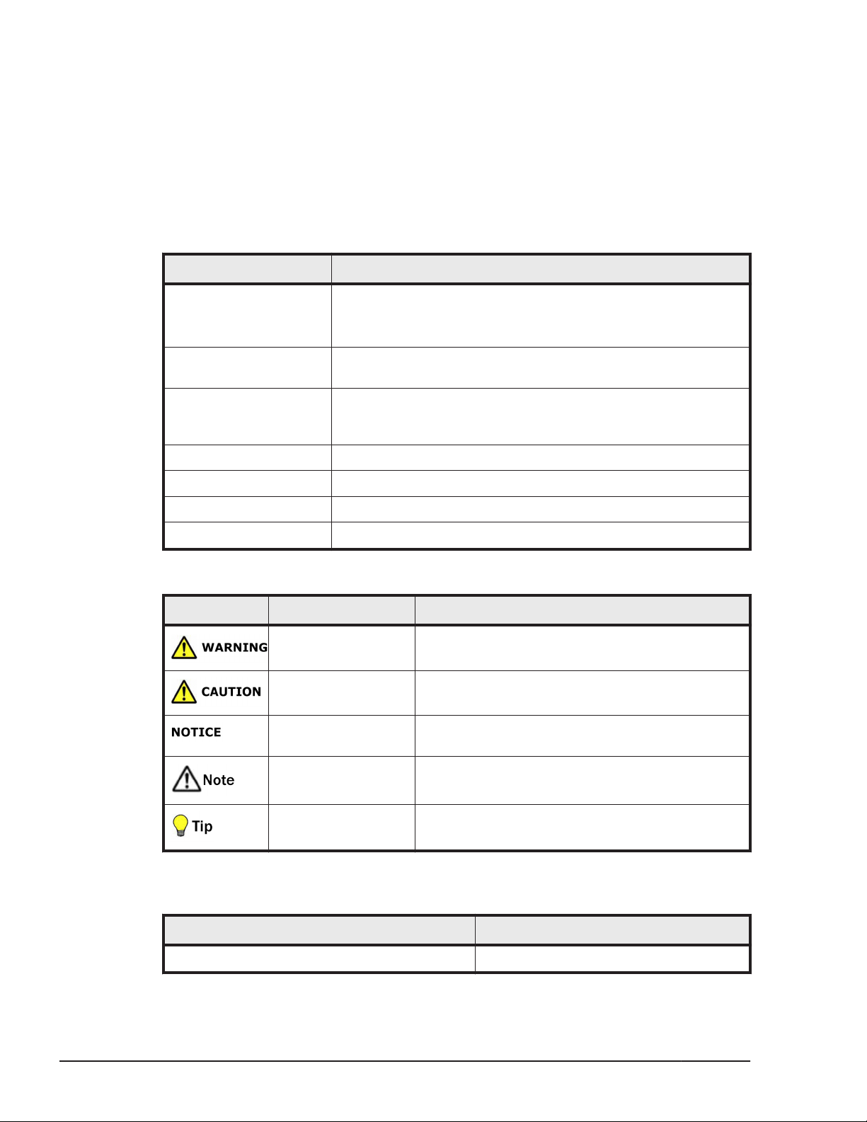
This document uses the following icons to draw attention to information:
Icon Meaning Description
WARNING This indicates the presence of a potential risk that
might cause death or severe injury.
CAUTION This indicates the presence of a potential risk that
might cause relatively mild or moderate injury.
NOTICE This indicates a risk of severe damage to the
equipment or damage to nearby items.
Note This indicates notes not directly related to injury
or severe damage to equipment.
Tip This indicates advice on how to make the best use
of the equipment.
The following table shows abbreviations of logical partitioning manager and
logical partition.
xii
Term Abbreviation
logical partitioning manager LPAR manager or LP
Preface
Hitachi Compute Blade 500 Series Logical partitioning manager User's Guide
Page 13
Term Abbreviation
logical partition LPAR
Convention for storage capacity values
Physical storage capacity values (for example, disk drive capacity) are
calculated based on the following values:
Physical capacity unit Value
1 kilobyte (KB)
1 megabyte (MB)
1 gigabyte (GB)
1 terabyte (TB)
1 petabyte (PB)
1 exabyte (EB)
1,000 (103) bytes
1,000 KB or 1,0002 bytes
1,000 MB or 1,0003 bytes
1,000 GB or 1,0004 bytes
1,000 TB or 1,0005 bytes
1,000 PB or 1,0006 bytes
Logical storage capacity values (for example, logical device capacity) are
calculated based on the following values:
Logical capacity unit Value
1 block 512 bytes
1 KB
1 MB
1 GB
1 TB
1 PB
1,024 (210) bytes
1,024 KB or 1,0242 bytes
1,024 MB or 1,0243 bytes
1,024 GB or 1,0244 bytes
1,024 TB or 1,0245 bytes
1 EB
Getting help
The Hitachi Data Systems customer support staff is available 24 hours a day,
seven days a week. If you need technical support, log on to the Hitachi Data
Systems Portal for contact information:
Comments
Please send us your comments on this document: doc.comments@hds.com.
Include the document title and number including the revision level (for
Hitachi Compute Blade 500 Series Logical partitioning manager User's Guide
1,024 PB or 1,0246 bytes
https://portal.hds.com.
Preface
xiii
Page 14

example, -07), and refer to specific sections and paragraphs whenever
possible. All comments become the property of Hitachi Data Systems
Corporation.
Thank you!
xiv
Preface
Hitachi Compute Blade 500 Series Logical partitioning manager User's Guide
Page 15

LPAR manager Functions
This chapter explains the basic functions of LPAR manager.
LPAR manager Overview
□
Logical Partitioning
□
Logical Partitioning of Processors
□
Logical Partitioning of Memory
□
Logical Partitioning of PCI Devices
□
1
NIC (Network Interface Card)
□
FC (Fibre Channel)
□
USB/KVM
□
LPAR manager Functions
Hitachi Compute Blade 500 Series Logical partitioning manager User's Guide
1-1
Page 16
LPAR manager Overview
LPAR manager logically partitions the physical resources of one server blade
to create multiple server environments, each of which can operate
independently.
Each of the server environments constructed in this way from partitioned
physical resources is called an LPAR (Logical PARtition). It is possible to run a
different operating system on each LPAR simultaneously.
The operating system on an LPAR is called a guest OS. Each LPAR operates as
a completely independent and isolated server environment, and the guest OS
running on an LPAR is not affected by other LPARs.
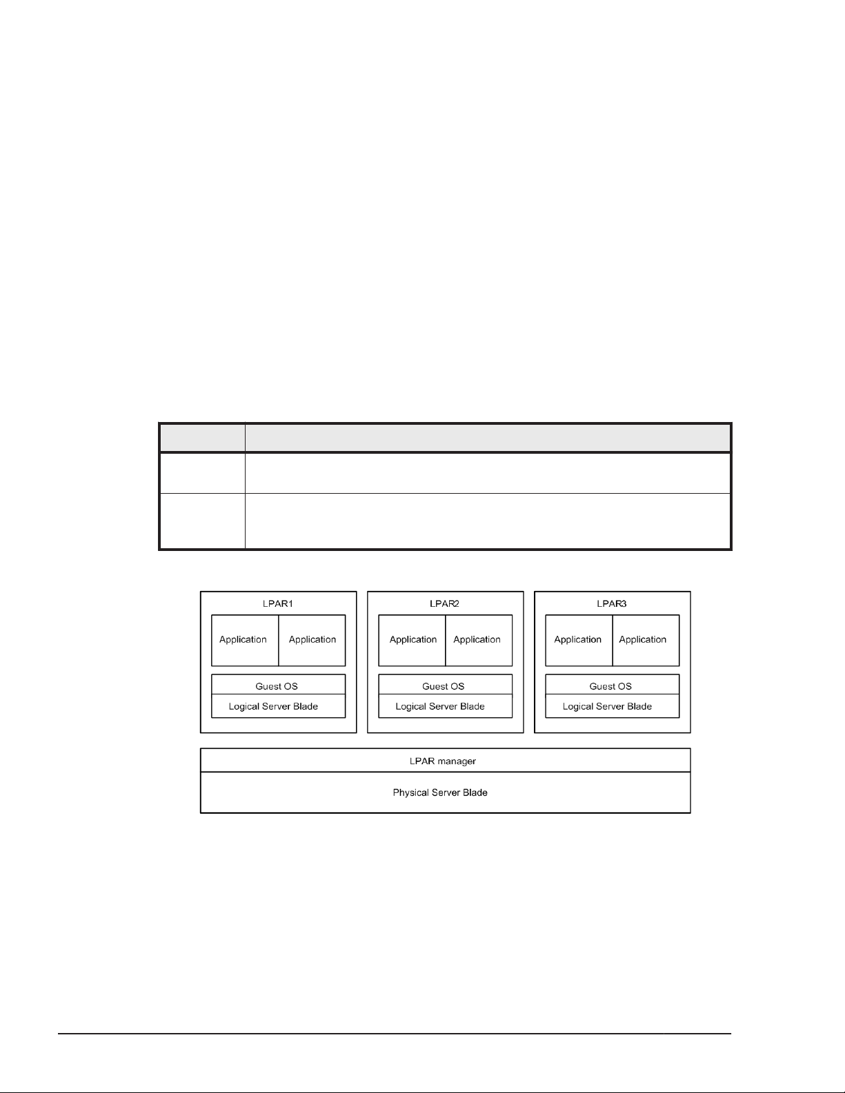
The mode in which a server blade is logically partitioned to allow the
operation of multiple LPARs is called the LP mode. The conventional mode of
operating a server blade without partitioning is called the Basic mode.
Unless explicitly specified, the terms "physical" and "logical" are used in this
chapter as defined in the table below.
Table 1-1 Physical and Logical resources
Term Description
Physical Indicates the resources that actually exist in the system. "Physical" is
sometimes omitted, except where this would cause confusion.
Logical Indicates the logical resources that exist on an LPAR or for software on
LPARs. Thus, there may or may not exist an actual resource for each logical
resource.
An image when the system is booted in the LP mode is as follows:
Figure 1-1 System Activation in the LP mode
In addition, in this chapter:
1-2
• Symbols embraced by square brackets [ ] indicate keys on the keyboard.
• If two keys are joined by a "+", such as "A + B", it means the two keys
are to be pressed together
LPAR manager Functions
Hitachi Compute Blade 500 Series Logical partitioning manager User's Guide
Page 17
Logical Partitioning
Dedicated Resources and Shared Resources
Although the LP mode makes it possible to logically partition the hardware
resources of a server blade, the method of logical partitioning varies
depending on the hardware resource.
Some types of logical partitioning are shown in the table below.
Term Description
Table 1-2 Type of Logical Partitioning
Typical
Hardware
Resources
Dedicated The LPAR to which a hardware resource
has been allocated dedicatedly uses the
hardware resource and other LPARs
cannot use the hardware resource.
To switch the LPAR that can use
resources, make sure to shut down the
LPAR once to change the configuration
definition.
Shared Time-shared The particular LPARs to which a hardware
resource has been allocated timeshare
the hardware resource.
LPAR manager keeps switching LPARs
that can use the device at very short time
intervals.
Exclusiveshared
One of the particular LPARs to which a
hardware resource has been allocated
exclusively uses the hardware resource.
The LPAR using the resource can be
switched dynamically.
Processors
Memories
PCI devices
Processors
PCI devices
Serial ports
USB devices
Remote
Console
Figure 1-2 Logical Partitioning of Hardware Resources
LPAR manager Functions
Hitachi Compute Blade 500 Series Logical partitioning manager User's Guide
1-3
Page 18

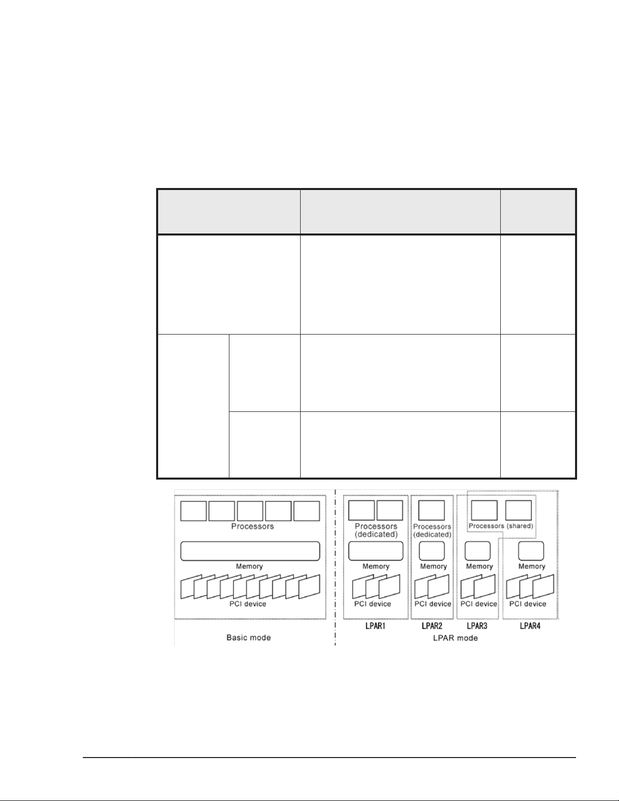
Logical Partitioning of Processors
The method of logically dividing the physical processor is referred to as the
scheduling mode. You can select dedicated mode or shared mode for the
scheduling mode. Different features of each mode are shown in the table
below.
Table 1-3 Processor Scheduling Mode
Mode Description
Dedicated
Mode
Shared
Mode
• The logical processor on an LPAR dedicatedly
uses the corresponding physical processor.
• Since there is no overhead for switching the
physical processors between the logical
processors, the LPAR performs faster.
• For each LPAR, it is possible to specify the
number of dedicated logical processors
assigned. (However, it is not possible to specify
more than the number of physical processors
available.)
• Physical processors are time-shared among the
logical processors defined in the LPAR for which
the shared mode is specified.
• The utilization rate of the physical processors
can be set dynamically for each LPAR, allowing
flexible use of physical processor resources.
• The number of logical processors to be used in
the shared mode can be set for each LPAR. (It
is possible to specify more than the number of
physical processors available, but this
operations may cause the extremely slow
down.)
Recommended
System
• System required
high processing
performance
• System required
critical time
period and high
processing in
performance
• System required
cost efficiency
and flexibility
rather than high
processing
performance
• System required
balanced
processing
between LPARs
1-4
Dedicated Mode
Example of Dedicated Mode is below
LPAR manager Functions
Hitachi Compute Blade 500 Series Logical partitioning manager User's Guide
Page 19
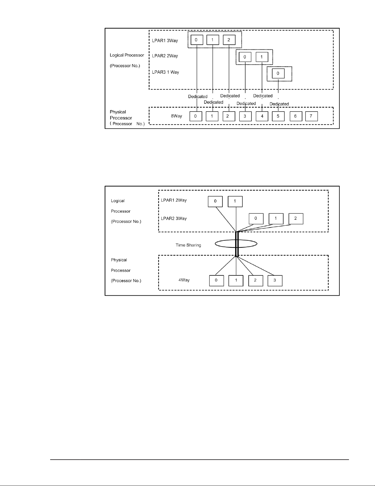
Figure 1-3 Processor Assignment of Dedicated Mode
Shared Mode
Example of Dedicated Mode is below
Figure 1-4 Processor Assignment of Shared Mode
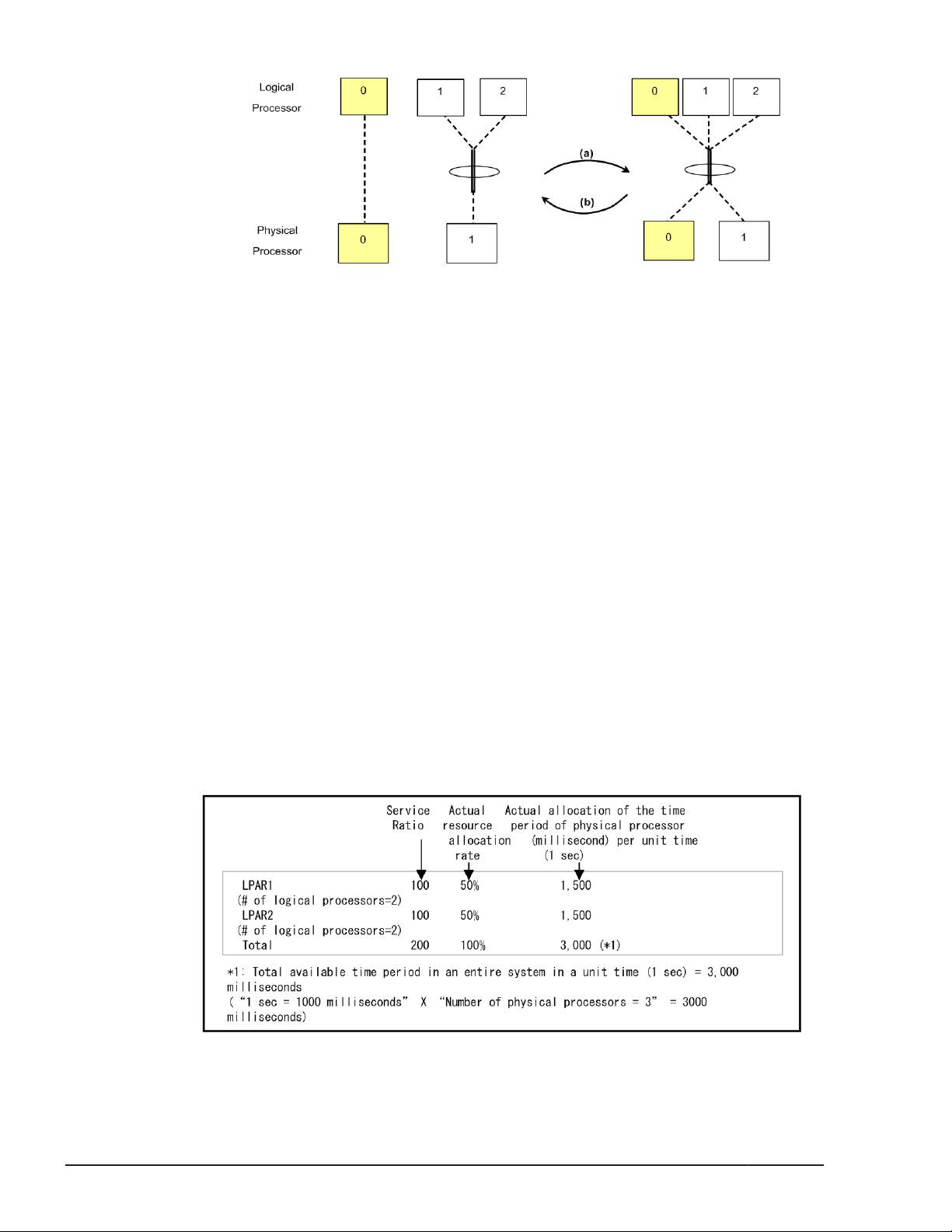
Scheduling mode dynamically change
Shared and dedicated LPARs can be switched dynamically without
deactivating.
a. The Scheduling mode of arbitrary Logical processor can be changed from
dedicated mode to shared mode.
b. The Scheduling mode of arbitrary Logical processor can be changed from
shared mode to dedicated mode.
LPAR manager Functions
Hitachi Compute Blade 500 Series Logical partitioning manager User's Guide
1-5
Page 20
Service Ratio
To the LPARs in the Shared Processor Mode, you can set the relative
processor resource allocation rate (called 'Service Ratio'), which represents
the ratio of the time period in which the LPAR actually run on the physical
processors (called 'Service Time'). The Service Ratio can be specified from 1
to 999.
LPAR manager partitions the performance of the physical processor used in
shared mode in 1 percent unit. LPAR manager calculates the relative
allocation rate of the service time with 10-millisecond time-slice accuracy,
which equals 1% of a unit processor time (1 second).
Service ratio has a meaning only to LPAR of shared mode. Service ratio does
not have any meaning to LPAR of shared mode, and cannot be assigned.
The examples of the relations between Service Ratio and allocation rate are
as follows.
(Example 1)
This example shows the allocation rates of LPAR1 (Service Ratio=100, the
number of the logical processors=2) and LPAR2 (Service Ratio=100, the
number of the logical processors=2) when the number of the physical
processor can be used by the shared mode LPARs is 3.
Figure 1-5 Scheduling mode dynamically change
1-6
Figure 1-6 Service Ratio Example 1
LPAR manager Functions
Hitachi Compute Blade 500 Series Logical partitioning manager User's Guide
Page 21
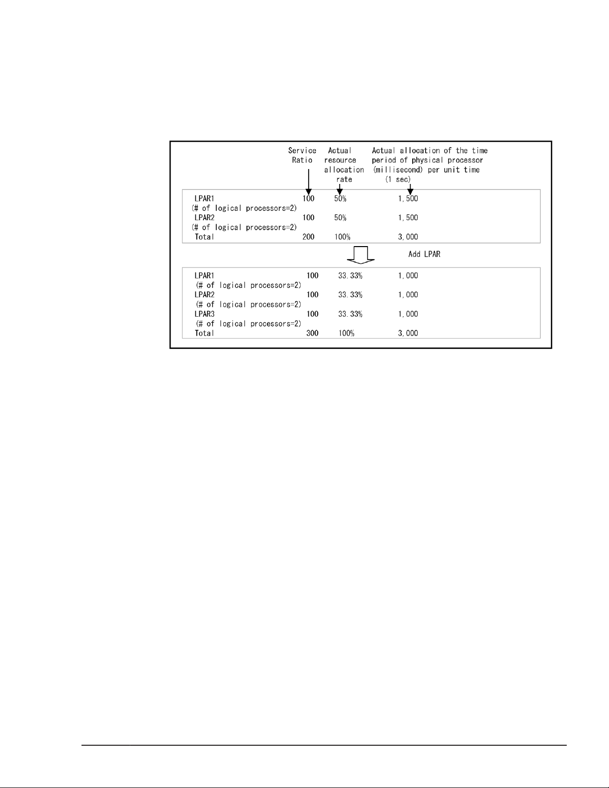
(Example 2)
This example shows the allocation rates of LPAR1 (Service Ratio=100, the
number of the logical processors=2), LPAR2 (Service Ratio=100, the number
of the logical processors=2) and LPAR3 (Service Ratio=100, the number of
the logical processors=3), when the number of the physical processor can be
used by the shared mode LPARs is 3, and LPAR3 is added while LPAR1 and
LPAR2 are running.
LPAR manager modifies the allocation rate from the shared LPAR definition
when it meets the following condition:
• If the allocation rate for the calculation per logical processor is less than 1
• If the number of logical processors allocated to a single LPAR does not
Idle Detection
A shared mode LPAR, which enabling its idle detection and not using so much
CPU compared to the allocated rate, can give its processor time to another
shared mode LPAR requiring it. The busy shared mode LPAR that takes over
the processor time can use more processor-time than the allocation rate. As a
result, the system can use CPUs time more efficiently.
Figure 1-7 Service Ratio Example 2
%, the service rate is compensated so that the time in which a single
logical processor uses the physical processor becomes 1% (10
milliseconds) of the unit processor time (1 second).
satisfy the assigned allocation rate, the allocation rate is compensated to
the one that is based on the number of logical processors.
LPAR manager Functions
Hitachi Compute Blade 500 Series Logical partitioning manager User's Guide
1-7
Page 22
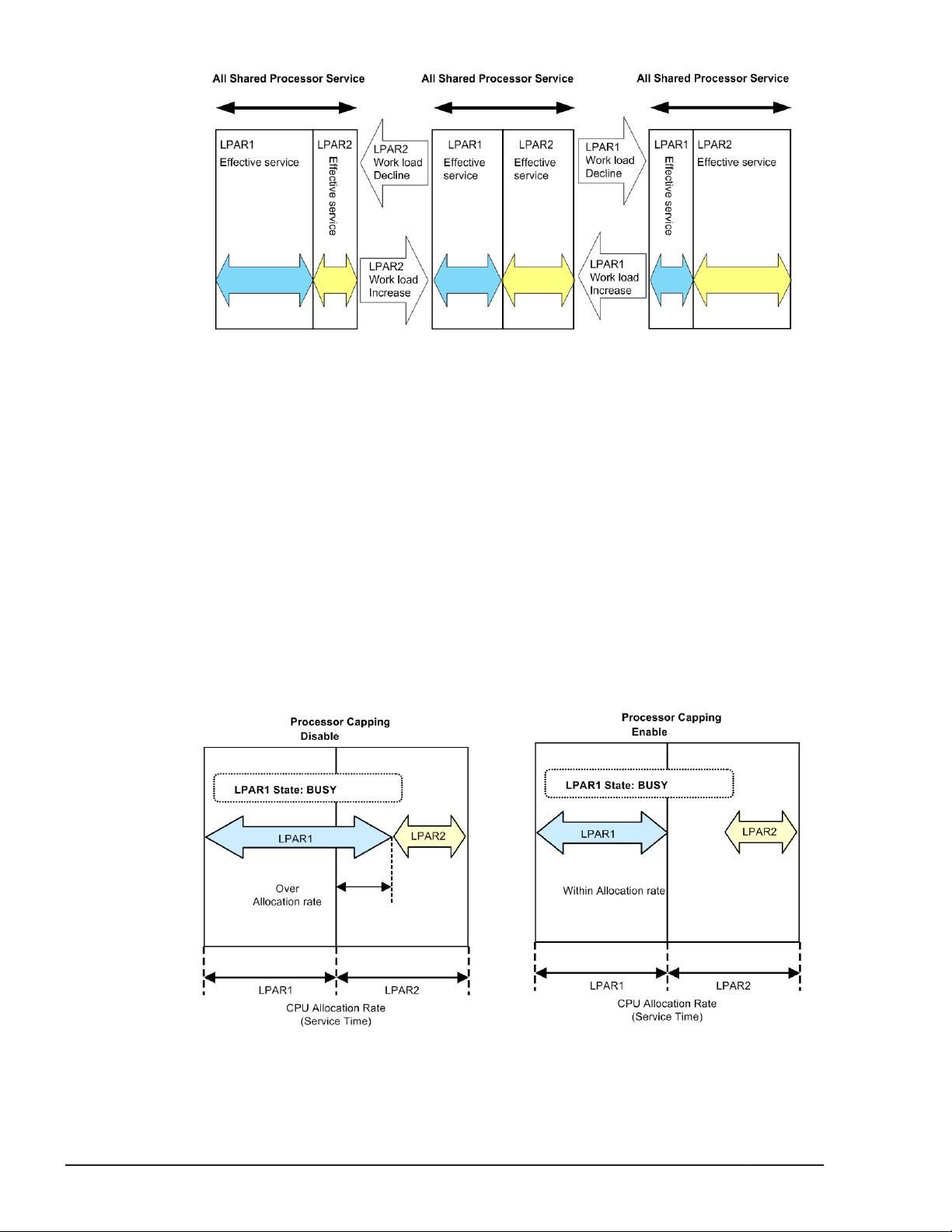
Processor Capping
With the processor capping function on, the shared mode LPAR does not take
on the unused (idle) capacity of other LPARs even if the LPAR requires more
performance than its allocation rate (busy status). Therefore, the LPAR's
processor-time never uses more processor-time the allocation rate, even if it
is busy. However, because the LPAR manager allocation rate control allows a
tolerance of 1% for each unit of processor-time, a shared mode LPAR is
allocated a maximum processor-time that is 1% greater than the total service
time of the physical processors assigned to it, and may exceed the allocation
rate.
Note that the processor capping function does not affect the execution of the
dedicated mode LPARs. Also processor capping has a meaning only to LPAR of
shared mode. Processor capping does not have any meaning to LPAR of
dedicated mode, and it cannot assign.
Figure 1-8 Idle Detection
1-8
Figure 1-9 Processor Capping
LPAR manager Functions
Hitachi Compute Blade 500 Series Logical partitioning manager User's Guide
Page 23
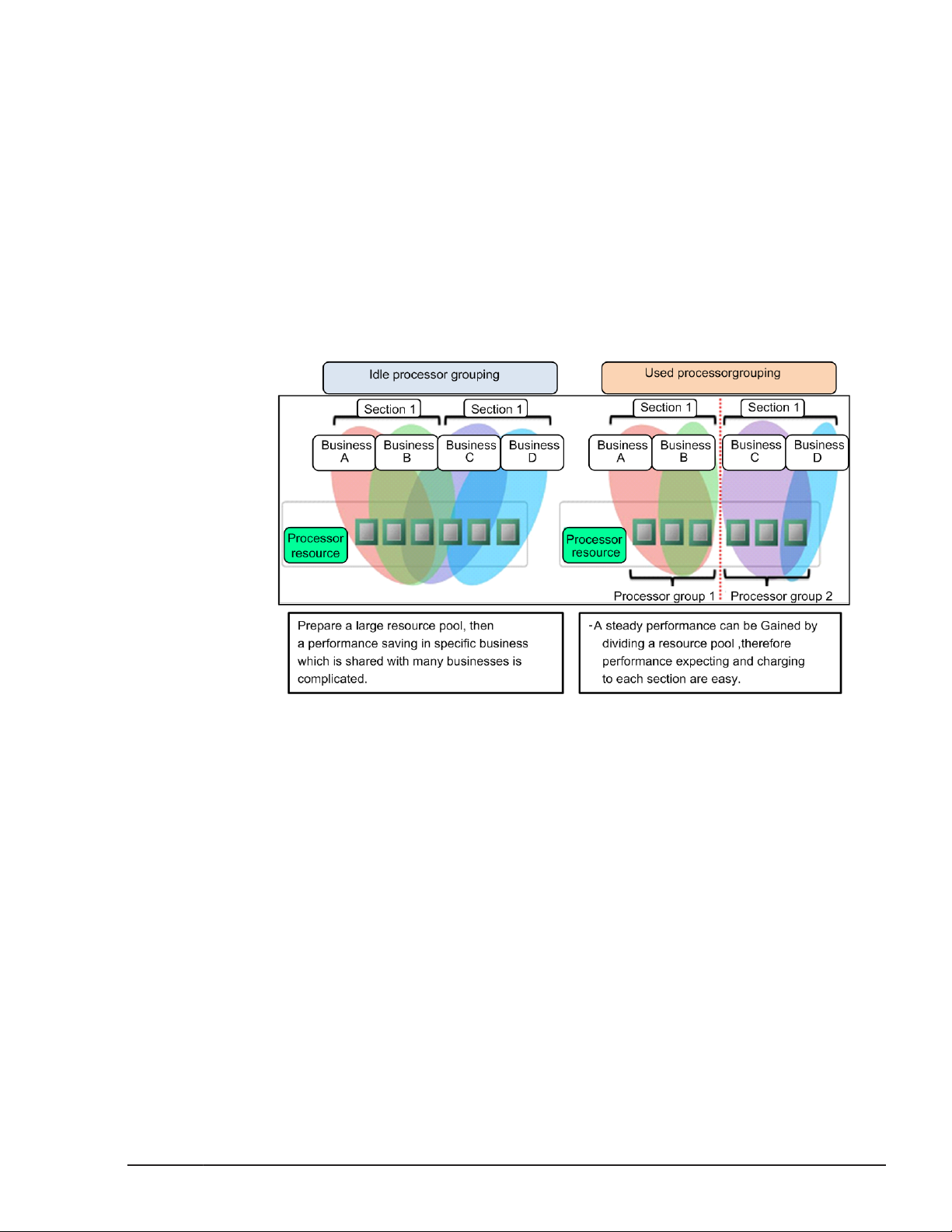
Processor Group
You can restrict the use of physical processors for a group of LPARs by
forming a group of physical processors with one processor at the least. Any
number can be defined as a number of a physical processor group. A
processor with no processor number defined belongs to the processor group
"0". A processor group number can be specified by the core.
Overview
A function which defines a processor core as a group and restricts the range
of a shared processor to being in a group. It is possible to restrict in a group
with effect of load-fluctuating by above mentioned. It is possible to define
group by every user section and charge to an allocated processor
performance.
Figure 1-10 Assignment of Processor Group
Change Group Assignment of Processor
Performance of processor group can be changed by changing group
assignment of processors. Definition of processor which changed group
assignment can change from shared mode to dedicated mode. Changing
group assignment of processor number 2 is shown below.
LPAR manager Functions
Hitachi Compute Blade 500 Series Logical partitioning manager User's Guide
1-9
Page 24
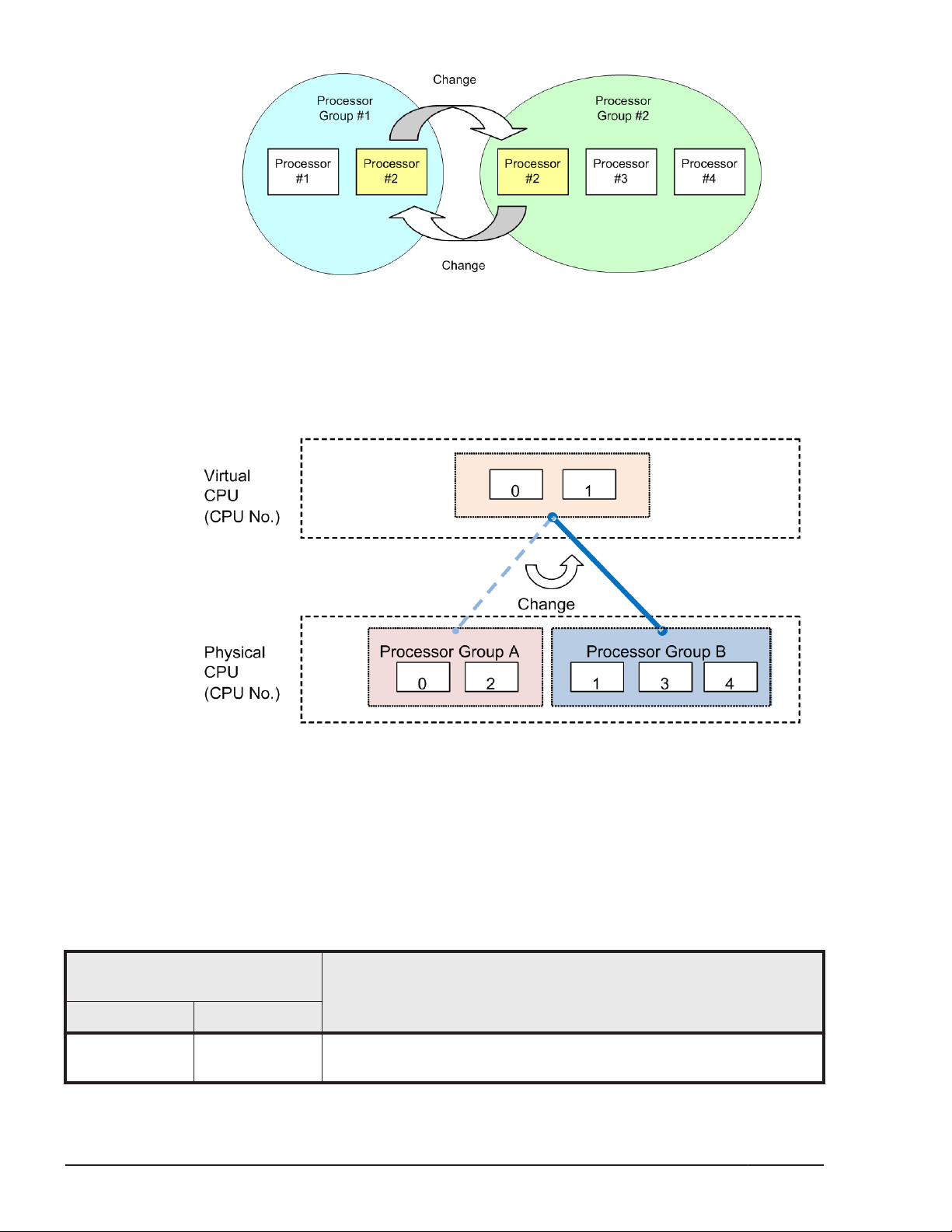
Figure 1-11 Change of Processor Group
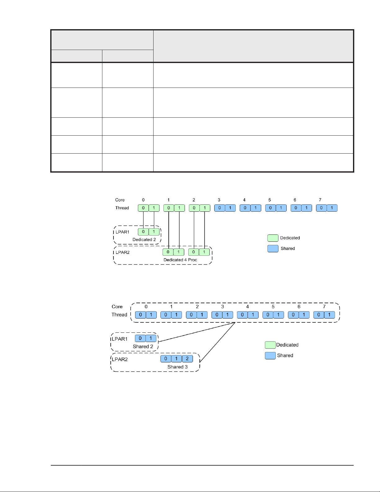
Change Processor Group Assignment of LPAR
Assigned processor group can dynamically change to other group. All of
assigned processors to the LPAR have to define to shared mode before
changing the group.
Figure 1-12 Change Assignment of Processor Group
Hyper Threading
Total performance of the LPAR manager increases up to 20% by enabling
Hyper Threading definition.
The LPAR manager performance is affected by processor assignment.
Table 1-4 Processor Assignment Mode
Assignment Mode
(Processor Number)
LPAR1 LPAR2
Dedicated (2) Dedicated (4) Performance of LPARs not interfere each other.
Performance increases by assigning of even number processors.
1-10
Hitachi Compute Blade 500 Series Logical partitioning manager User's Guide
LPAR manager Functions
Description
Page 25
Assignment Mode
(Processor Number)
Description
LPAR1 LPAR2
Assign threads which are on the same core to the identical LPAR.
(Don't assign the threads to the different cores)
Proper assignment for Database servers / Application servers.
Dedicated (2) Dedicated (3) Processor number can be assigned more than physical number.
Odd or even number processors can be assigned to the one LPAR.
Proper assignment for File servers / Web servers
Dedicated (3) Dedicated (3) Not recommend (LPAR performance is affected from load of other
LPARs)
Dedicated (3) Dedicated (2) Not recommend (LPAR performance is affected from load of other
LPARs)
Dedicated (3) Dedicated (3) Not recommend (LPAR performance is affected from load of other
LPARs)
Assigned even number processors to LPAR with Dedicated mode.
Figure 1-13 Processor Assignment Mode 1
Assigned processors to LPAR with Shared mode.
Figure 1-14 Processor Assignment Mode 2
LPAR manager Functions
Hitachi Compute Blade 500 Series Logical partitioning manager User's Guide
1-11
Page 26
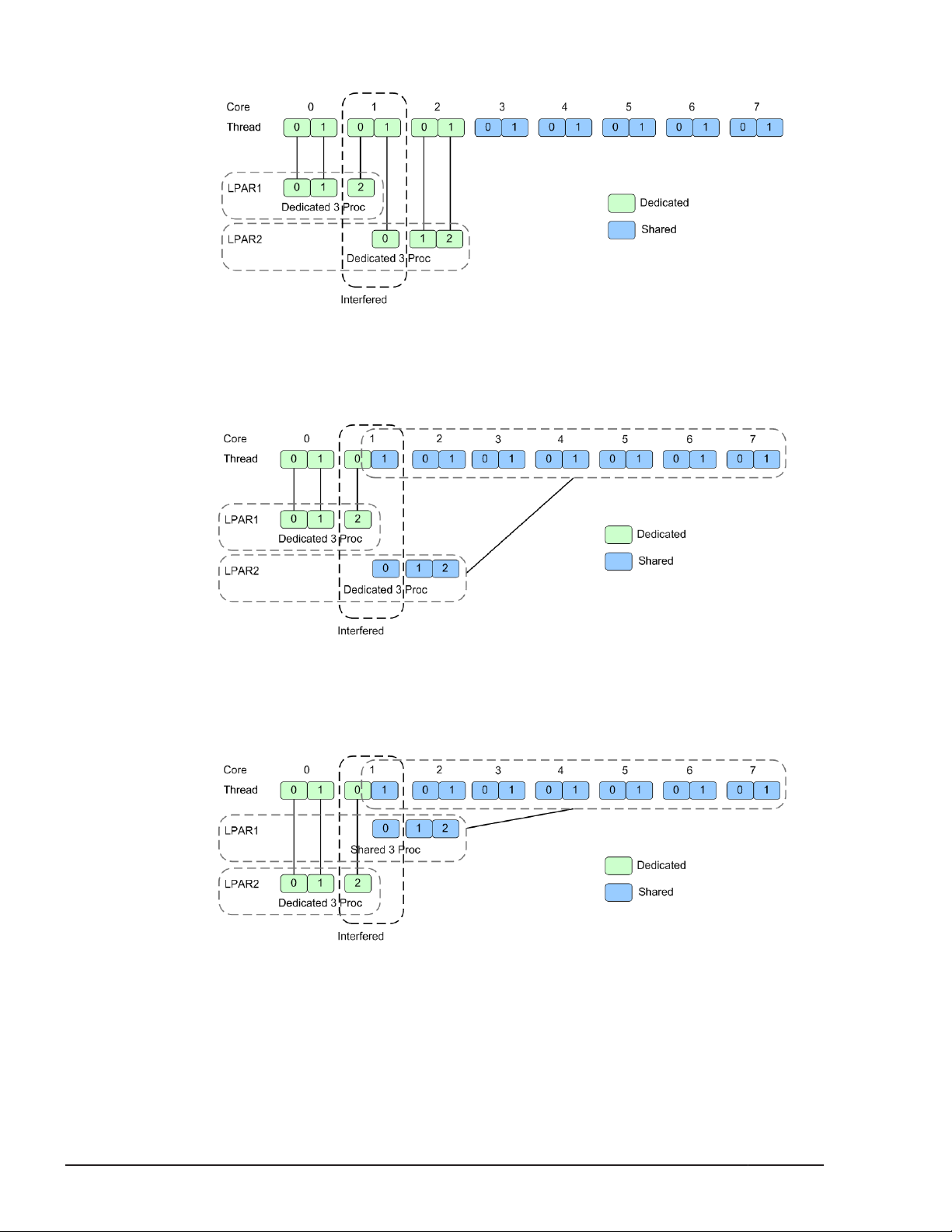
Assigned odd number processors to LPAR with Dedicated mode.
Figure 1-15 Processor Assignment Mode 3
Assigned odd number processors to LPAR with Dedicated / Shared
mixing mode.
PRTE
Figure 1-16 Processor Assignment Mode 4
Assigned odd number processors to LPAR with Shared / Dedicated
mixing mode.
Figure 1-17 Processor Assignment Mode 5
The PRTE function provides a timer that can be referred without intervention
of the LPAR manager.
1-12
LPAR manager Functions
Hitachi Compute Blade 500 Series Logical partitioning manager User's Guide
Page 27

We recommend that you basically set the PRTE function to "No": a default
value.
Enabling the PRTE function may bring performance improvement of programs
that frequently retrieve time, in Windows.
Note:
• Enabling this function brings guest OS operation different from that with
this function disabled. When you enable or disable the PRTE function, we
recommend that you evaluate guest OS behavior in advance.
Restriction
The following shows restrictions for this function.
• Do not assign more than 64 of logical processors to an LPAR with its PRTE
function enabled.
• Do not use the NIC teaming functionality an LPAR with its PRTE function
enabled.
Supported OS
The following OSs support the PRTE function.
Make sure not to set the PRTE function to "Yes" for other OSs.
• Windows Server 2012
• Windows Server 2012 R2
Method of setting the PRTE function
You are able to change the setting of the PRTE function only for deactivated
LPARs.
The method of setting the PRTE function is as follows.
1. Connect to the LPAR manager screen, and then display the Logical
Partition Configuration screen.
2. Use the F11 and F12 keys to scroll the page to the left and right. Place
the cursor on the PRTE column of the LPAR row, and then press Enter.
The sub-screen is displayed.
3. Select Yes, and then press Enter.
Logical Partitioning of Memory
The memory size to be allocated to each LPAR can be specified for each LPAR
(in multiples of 256 MB). Each guest OS has an exclusive use of the memory
assigned to its LPAR. LPAR manager automatically determines which physical
memory offset area(s) to allocate to an LPAR when the LPAR is activated.
LPAR manager Functions
Hitachi Compute Blade 500 Series Logical partitioning manager User's Guide
1-13
Page 28
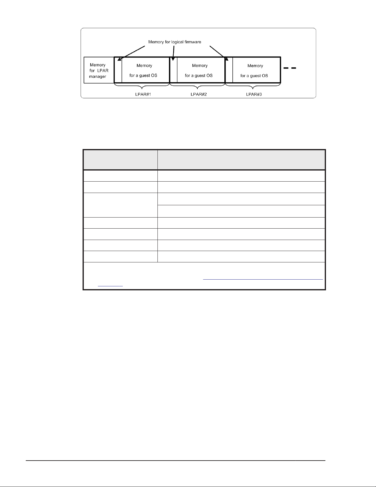
Figure 1-18 Memory Mapping of Logical Partitioning
• Memory for LPAR manager
The following table describes the physical memories that are used with
LPAR manager.
Server blade type
CB 520H A1/B1/B2 2048 MB
CB 520H B3 2560 MB
CB 520H B4
CB 520A A1 2048 MB
CB 540A A1/B1 2048 MB
CB 520X B1/B2 3072 MB
CB 520X B3 6144 MB
Notes:
1. For the value of MM Config Base, see Table 5-2 Server Blade and EFI settings on
page 5-4
Amount of memory necessary for operating LPAR
manager
4096 MB (when MM Config Base is set to 2048 MB1)
6144 MB (when MM Config Base is set to 3072 MB1)
• Memory for logical firmware
Logical firmware uses a part of memory space assigned to each LPAR.
Memory that logical firmware uses, in general, can be estimated from the
following calculation formulas:
– [Less than 8 GB memory assigned to LPAR]
1-14
¢
0.6% of memory assigned to LPAR + number of logical processors x
2.25 MB + 65 MB
– [8 GB or larger memory assigned to LPAR]
¢
0.25% of memory assigned to LPAR + number of logical processors x
2.25 MB + 80 MB
• Memory for a guest OS
Memory space available for a guest OS is calculated by subtracting the
amount of memory the logical firmware uses from the amount assigned
to the LPAR. This memory size is usually same as the available memory
size for a guest OS (indicated memory size in a guest OS). However, all
LPAR manager Functions
Hitachi Compute Blade 500 Series Logical partitioning manager User's Guide
Page 29

Note:
• When the amount of memory for a guest OS is not enough against the
Guest NUMA
Overview
NUMA (Non-Uniform Memory Access) is an architecture where memory is
shared in a multiprocessor computer system. To create an LPAR that meets
all of the conditions listed below, we recommend that you use a NUMA
configuration so you can easily improve memory access and memory
bandwidth. The NUMA running on an LPAR is called a guest NUMA.
• You are creating an LPAR on a server blade in an SMP configuration.
• You are creating an LPAR with the processor scheduling mode set to
allocated memory size may not be available depending on the
specification and environment of guest OS.
amount applications use, memory swap may happen to cause
performance degradation. When assigning an amount of memory, make
sure to take the memory amount.
dedicated mode.
LPAR manager supports the following two methods for configuring logical
processors for the guest NUMA: physical processor binding (for 02-0X or
later) and physical NUMA node binding (for 02-40 or later). Physical
processor binding is the method for associating logical processors with
physical processors. Physical NUMA node binding is the method for
associating logical processors with physical NUMA nodes. The table below
explains specific differences between these binding methods with regard to
how to configure an LPAR.
Item
How to set the
number of logical
processors
How to select a
physical processor to
be assigned to a
logical processor
Physical processor
binding
Sets the number of logical
processors in the entire
LPAR.
Before the LPAR is
activated, the user specifies
the number of the physical
processor that the user will
manually assign.
Physical NUMA node binding
Sets the number of logical
processors for each node
When the LPAR is activated, LPAR
manager selects, in the ascending
order of numbers, physical
processors that exist in the
automatically specified node and
can be assigned.
Setting up a guest NUMA
The following describes how to set up a guest NUMA:
If the physical processor binding is used, follow the procedure below.
1. Configure the NUMA for the EFI.
LPAR manager Functions
Hitachi Compute Blade 500 Series Logical partitioning manager User's Guide
1-15
Page 30

Make sure that the NUMA setting for the EFI is enabled on the Web
console.
For details, see the Hitachi Compute Blade 500 Series Web Console User's
Guide.
2. Check the guest NUMA support of LPAR manager.
Make sure that the LPAR manager firmware version is 02-0X or later.
For details, see
3. Configure the guest NUMA for the LPAR.
Enable the guest NUMA setting of the LPAR.
For details, see
4. Specify the method for configuring logical processors for the guest NUMA.
For the LPAR manager firmware version 02-2x or earlier:
Can not changed configuring logical processors for the guest NUMA.
Always behavior physical processor binding.
For the LPAR manager firmware version 02-40 or later:
Specify physical processor binding as the method for configuring logical
processors for the guest NUMA. Note that the default method is the
physical processor binding if you change the guest NUMA setting from
"disabled" to "enabled".
For details, see the HVM Management Command (HvmSh) Operation
Guide.
5. Set the processor scheduling mode.
Set the processor scheduling mode to dedicated mode.
For details, see
6. Specify the number of logical processors.
Specify the number of logical processors in the entire LPAR. For details,
Logical Partition Configuration on page 7-9.
see
If you want to assign processors from multiple nodes, you must ensure
that each of the nodes will have the same number of processors assigned.
7. Assign a processor.
Specify the number of logical processors in the entire LPAR.
For details, see
For details about the node to which the physical processor belongs, see
Physical Processor Configuration on page 7-32.
8. Specify the memory.
Manually specify the memory on the node to which the physical processor
belongs.
For details, see
Firmware Version Information on page 7-131.
Logical Partition Configuration on page 7-9.
Logical Partition Configuration on page 7-9.
Logical Processor Configuration on page 7-28.
Logical Partition Configuration on page 7-9.
1-16
If the physical NUMA node binding is used, follow the procedure below.
1. Configure the NUMA for the EFI.
Make sure that the NUMA setting for the EFI is enabled on the Web
console.
For details, see the Hitachi Compute Blade 500 Series Web Console User's
Guide.
LPAR manager Functions
Hitachi Compute Blade 500 Series Logical partitioning manager User's Guide
Page 31

2. Check the guest NUMA support of LPAR manager.
Make sure that the LPAR manager firmware version is 02-40 or later.
For details, see Firmware Version Information on page 7-131.
3. Configure the guest NUMA for the LPAR.
Enable the guest NUMA setting of the LPAR.
For details, see
Logical Partition Configuration on page 7-9.
4. Specify the method for configuring logical processors for the guest NUMA.
Specify physical NUMA node binding as the method for configuring logical
processors for the guest NUMA.
For details, see the HVM Management Command (HvmSh) Operation
Guide.
5. Set the processor scheduling mode.
Set the processor scheduling mode to dedicated mode.
For details, see
Logical Partition Configuration on page 7-9.
6. Specify the number of processors.
Specify the number of logical processors for each node. For details, see
the HVM Management Command (HvmSh) Operation Guide.
If you want to assign processors from multiple nodes, you must ensure
that each of the nodes will have the same number of processors assigned.
7. Specify the memory.
Specify the memory for each node.
For details, see
Logical Partition Configuration on page 7-9.
Notes on the guest NUMA
Remember the following if you want to use the guest NUMA:
• If you change the MM Config Base setting for EFI, the memory size that
can be allocated to each node changes. For this reason, activation of the
LPAR for which a memory node is specified might fail due to insufficient
memory on the target node. If you change the MM Config Base setting,
you must review the memory node number and the memory size
allocated to each LPAR. For details on how to review the memory node
number and the memory size allocated to each LPAR, see
Configuration on page 7-9.
• If the guest NUMA is enabled in an LPAR, the default method for
configuring logical processors for the guest NUMA is physical processor
binding. This default method applies under the following circumstances:
¢
A change is made to enable the guest NUMA, which has previously
been disabled.
¢
LPAR configuration information is inherited in which the guest NUMA is
enabled. This LPAR configuration information was previously saved in
LPAR manager when LPAR manager did not support the physical
NUMA node binding.
Logical Partition
LPAR manager Functions
Hitachi Compute Blade 500 Series Logical partitioning manager User's Guide
1-17
Page 32

L3 cache allocation functionality
Overview of the L3 cache allocation functionality
You can use the L3 cache allocation functionality to divide the L3 cache
among multiple LPARs and allocate part of the divided cache to each LPAR.
This functionality uses Cache Allocation Technology (CAT), which is provided
as part of Intel Resource Director Technology (RDT).
If, for example, you operate an LPAR that requires response performance
(web server) and an LPAR that puts a high load on the memory (database) at
the same time, data of the LPAR (web server) might be forced out from the
L3 cache, and degradation or variance in response performance might occur.
You can prevent such degradation or variance in response performance by
using the L3 cache allocation functionality to secure the L3 cache space
required for the LPAR (web server).
By default, the entire L3 cache is allocated to each LPAR, but you can
dynamically change the size of the L3 cache space that is allocated to each
LAPR. Note, however, that you can change the L3 cache allocation only for
LPARs to which processors have been allocated in dedicated mode.
You can allocate L3 cache space to LPARs by using the capacity bit mask
(CBM) format (a mask value format). By using a CBM, you can specify not
only the size of the L3 cache space to be allocated to LPARs, but also detailed
settings such as the distance and overlapping of L3 cache allocation among
LPARs. Each specified CBM value must be in the range of the implemented bit
width of the CBM and must be a combination of consecutive ones (1). For
example, if the implemented bit width of the CBM is 20, FFFFFh, 0FF00h, and
0003Ch are acceptable, but values such as 10001h, 00100h, and 0F0F0h are
not acceptable. As shown below, there are three possible combinations of
CBMs for multiple LPARs. In the following figure, the implemented bit width of
CBMs is 8.
1-18
LPAR manager Functions
Hitachi Compute Blade 500 Series Logical partitioning manager User's Guide
Page 33

Figure 1-19 L3 cache allocation to LPAR
In the case indicated by (1), all three LPARs can access the entire L3 cache.
In the case indicated by (2), the L3 cache space allocated to the LPAR of
lower priority can be shared with the LPAR of higher priority. In the case
indicated by (3), the cache can be divided among isolated LPARs.
To allocate L3 cache space to LPARs, use the HVM management command
(HvmSh). You can also use the HVM management command (HvmSh) to
display the CAT-related configuration information required to use the L3
cache allocation functionality, and the usage status of the L3 cache allocation
functionality. For details, see the HVM Management Command (HvmSh)
Operation Guide.
Enabling the L3 cache allocation functionality
To enable the L3 cache allocation functionality:
1. From the Web console, enable Performance tuning options.
For details, see
2. Specify the L3 cache allocation settings by using the HVM management
command (HvmSh), execute the opr LparCatCbm command.
For details, see the HVM Management Command (HvmSh) Operation
Guide.
Performance tuning options on page 2-21.
Logical Partitioning of PCI Devices
The method of logically dividing the physical processor is referred to as the
scheduling mode. You can select dedicated mode or shared mode for the
scheduling mode. Different features of each mode are shown in the table
below.
LPAR manager Functions
Hitachi Compute Blade 500 Series Logical partitioning manager User's Guide
1-19
Page 34

Table 1-5 Assignment Mode of PCI Device
Scheduling
Mode
Dedicated
Mode
Shared Mode A single PCI device is assigned to multiple
Exclusive
shared mode
A single PCI device is assigned to a single LPAR
(guest OS). The guest OS uses the assigned PCI
device exclusively, so that its I/O performance
is stable.
When 2 ports are implemented in a PCI device,
each port cannot be assigned to a separate
LPAR.
LPARs (guest OSs). Each guest OS can use the
assigned PCI device at the same time without
knowing that the PCI device is shared with other
OSs.
NIC performance of an LPAR is affected by I/O
load of other LPARs.
A single PCI device is assigned to a single LPAR
(guest OS). PCI device assignment can be
changed without stopping operation of LPAR. A
single LPAR can be used, multiple LPARs cannot
be used at the same time.
Features
Recommended
System
System required high
processing
performance
System required
critical time period and
high processing in
performance
System required cost
efficiency and
flexibility rather than
high processing
performance
System required
balanced processing
between LPARs
USB/KVM, and remote
console
Dedicated Mode
Example of Dedicated Mode is below.
Figure 1-20 PCI Device Assignment of Dedicated Mode
1-20
LPAR manager Functions
Hitachi Compute Blade 500 Series Logical partitioning manager User's Guide
Page 35

Shared Mode
Example of Dedicated Mode is below.
Figure 1-21 PCI Device Assignment of Shared Mode
Exclusively Shared Mode
Note:
• In CB 520X B1/B2/B3, a KVM device or a remote console are assigned to
a LPAR by Exclusive Shared Mode, however, a USB device is assigned to a
LPAR by Dedicated Mode.
Example of Exclusive Shared Mode is below.
Figure 1-22 PCI Device Assignment in Exclusive Shared Mode
LPAR manager Functions
Hitachi Compute Blade 500 Series Logical partitioning manager User's Guide
1-21
Page 36

NIC (Network Interface Card)
LPAR manager supports the following four virtual NIC functions. A shared
NIC, VF NIC, and virtual NIC are collectively called "Logical NIC".
Item Description
Dedicated NIC • Stable performance: not affected by other LPARs
• High-speed data transmission
Shared NIC • A physical NIC can be shared by multiple LPARs.
• Performance depends on the number of LPARs and traffic
volume.
• Less restrictions on NIC functions than VF NIC.
VF NIC • SR-IOV, a physical NIC function, is used. Supported physical
NIC, server blade, and OS are limited.
• High-speed data transmission equivalent to Dedicated NIC
• Lighter load on physical processors than Shared and Virtual
NIC
• Transmission bandwidth can be limited by the 100 Mbps.
Virtual NIC • Available only for inter-LPAR transmission
• No physical NIC is required.
Dedicated NIC
LPAR manager supports assigning of Dedicated NIC. Shared NIC is useful for
solving lack of hardware resources and increasing use efficiency of devices on
the virtual environment.
Dedicated NIC brings high performance for communication without influences
from other LPARs.
Shared NIC
Network segments for shared NICs can be assigned when the NIC scheduling
mode is set to shared mode.
NIC assigned the network segments is called "Shared NIC".
Network segments can be set on Virtual NIC Assignment Screen.
The maximum number of physical LAN controllers which can be assigned to
LPAR manager is 8 and the maximum number of physical ports which can be
assigned to LPAR manager is 16.
The following tables show a combination of logical port numbers, a detection
number of LAN controller and network segments for each hardware
configuration as examples.
1-22
Network segment 1a and 1b below are set as management paths.
LPAR manager Functions
Hitachi Compute Blade 500 Series Logical partitioning manager User's Guide
Page 37

Table 1-6 Example for CB 520H A1/B1/B2 when Onboard LAN Card is
installed (Emulex 10Gb 2ports)
Physical NIC
Onboard LAN
(Emulex 10Gb
2ports)
Notes:
1. The physical port number which exists on the system.
2. The logical port number which displays on the LPAR manager screen.
Physical Port
1
No.
0 0 1 1a
1 1 1b
Logical Port
2
No.
Detection No.
of LAN
controller
Network
segment
Table 1-7 Example for CB 540A A1/B1 when Onboard LAN Card is installed
(Emulex 10Gb 2ports)
Detection No.
of LAN
controller
Network
segment
Physical NIC
Onboard LAN1
(Emulex 10Gb
2ports)
Onboard LAN2
(Emulex 10Gb
2ports)
Physical Port
1
No.
0 0 1 1a
1 1 1b
0 0 2 2a
1 1 2b
Logical Port
2
No.
Notes:
1. The physical port number which exists on the system.
2. The logical port number which displays on the LPAR manager screen.
Table 1-8 Example for CB 520H A1/B1/B2/B3/B4 when Onboard LAN Card
is not installed (Emulex 10Gb 4ports)
Physical NIC
Mezzanine Card
1
(Emulex 10Gb
4ports)
Notes:
1. The physical port number which exists on the system.
2. The logical port number which displays on the LPAR manager screen.
Physical Port
1
No.
0 0 1 1a
1 1 1b
2 2 2 2a
3 3 2b
Logical Port
2
No.
Detection No.
of LAN
controller
Network
segment
LPAR manager Functions
Hitachi Compute Blade 500 Series Logical partitioning manager User's Guide
1-23
Page 38

Table 1-9 Example for CB 520A A1 when Onboard LAN Card is not installed
(Emulex 10Gb 4ports)
Physical NIC
Mezzanine Card
1
(Emulex 10Gb
4ports)
Notes:
1. The physical port number which exists on the system.
2. The logical port number which displays on the LPAR manager screen.
Physical Port
1
No.
0 2 2 2a
1 3 2b
2 0 1 1a
3 1 1b
Logical Port
2
No.
Detection No.
of LAN
controller
Network
segment
Table 1-10 Example for CB 540A A1/B1, CB 520X B1/B2/B3 when Onboard
LAN Card is not installed (Emulex 10Gb 4ports)
Detection No.
of LAN
controller
Network
segment
Physical NIC
Mezzanine Card
1
(Emulex 10Gb
4ports)
Physical Port
1
No.
0 0 1 1a
1 1 1b
2 2 2 2a
Logical Port
2
No.
3 3 2b
Mezzanine Card
3
(Emulex 10Gb
4ports)
Notes:
1. The physical port number which exists on the system.
2. The logical port number which displays on the LPAR manager screen.
3. NIC cannot be installed on Mezzanine Card 3 for CB 520X B1.
3
0 0 3 3a
1 1 3b
2 2 4 4a
3 3 4b
Table 1-11 Example for CB 520H A1/B1/B2/B3/B4 when Onboard LAN
Card is not installed (Broadcom 1Gb 4ports)
Detection No.
of LAN
controller
Network
segment
Physical NIC
Mezzanine Card
1
Physical Port
1
No.
0 0 1 1a
1 1 1b
Logical Port
2
No.
1-24
LPAR manager Functions
Hitachi Compute Blade 500 Series Logical partitioning manager User's Guide
Page 39

Physical NIC
(Broadcom 1Gb
4ports)
Notes:
1. The physical port number which exists on the system.
2. The logical port number which displays on the LPAR manager screen.
Physical Port
1
No.
2 2 1c
3 3 1d
Logical Port
2
No.
Detection No.
of LAN
controller
Table 1-12 Example for CB 520A A1 when Onboard LAN Card is not
installed (Broadcom 1Gb 4ports)
Network
segment
Physical NIC
Mezzanine Card
1
(Broadcom 1Gb
4ports)
Notes:
1. The physical port number which exists on the system.
2. The logical port number which displays on the LPAR manager screen.
Physical Port
1
No.
0 0 1 1a
1 1 1b
2 2 1c
3 3 1d
Logical Port
2
No.
Detection No.
of LAN
controller
Network
segment
Table 1-13 Example for CB 540A A1/B1, CB 520X B1/B2/B3 when Onboard
LAN Card is not installed (Broadcom 1Gb 4ports)
Detection No.
of LAN
controller
Network
segment
Physical NIC
Mezzanine Card
1
(Broadcom 1Gb
4ports)
Physical Port
1
No.
0 0 1 1a
1 1 1b
2 2 1c
Logical Port
2
No.
3 3 1d
Mezzanine Card
3
(Broadcom 1Gb
4ports)
Notes:
1. The physical port number which exists on the system.
2. The logical port number which displays on the LPAR manager screen.
3
0 0 2 2a
1 1 2b
2 2 2c
3 3 2d
LPAR manager Functions
Hitachi Compute Blade 500 Series Logical partitioning manager User's Guide
1-25
Page 40

Physical NIC
3. NIC cannot be installed on Mezzanine Card 3 for CB 520X B1.
Physical Port
1
No.
Logical Port
2
No.
Detection No.
of LAN
controller
Network
segment
Table 1-14 Example for CB 520H A1/B1/B2/B3/B4 when Onboard LAN
Card is not installed (Broadcom 1Gb 8ports)
Physical NIC
Mezzanine Card
1
(Broadcom 1Gb
8ports)
Notes:
1. The physical port number which exists on the system.
2. The logical port number which displays on the LPAR manager screen.
Physical Port
1
No.
0 0 1 1a
1 1 1b
2 2 1c
3 3 1d
4 4 2 2a
5 5 2b
6 6 2c
7 7 2d
Logical Port
2
No.
Detection No.
of LAN
controller
Table 1-15 Example for CB 520A A1 when Onboard LAN Card is not
installed (Broadcom 1Gb 8ports)
Detection No.
of LAN
controller
Physical NIC
Physical Port
1
No.
Logical Port
2
No.
Network
segment
Network
segment
1-26
Mezzanine Card
1
(Broadcom 1Gb
8ports)
Notes:
1. The physical port number which exists on the system.
2. The logical port number which displays on the LPAR manager screen.
0 0 1 1a
1 1 1b
2 2 1c
3 3 1d
4 4 2 2a
5 5 2b
6 6 2c
7 7 2d
LPAR manager Functions
Hitachi Compute Blade 500 Series Logical partitioning manager User's Guide
Page 41

Table 1-16 Example for CB 540A A1/B1, CB 520X B1/B2/B3 when Onboard
LAN Card is not installed (Broadcom 1Gb 8ports)
Physical NIC
Mezzanine Card
1
(Broadcom 1Gb
8ports)
Mezzanine Card
3
(Broadcom 1Gb
8ports)
3
Physical Port
1
No.
0 0 1 1a
1 1 1b
2 2 1c
3 3 1d
4 4 2 2a
5 5 2b
6 6 2c
7 7 2d
0 0 3 3a
1 1 3b
2 2 3c
3 3 3d
4 4 4 4a
5 5 4b
Logical Port
2
No.
Detection No.
of LAN
controller
Network
segment
6 6 4c
7 7 4d
Notes:
1. The physical port number which exists on the system.
2. The logical port number which displays on the LPAR manager screen.
3. NIC cannot be installed on Mezzanine Card 3 for CB 520X B1.
LPAR manager Functions
Hitachi Compute Blade 500 Series Logical partitioning manager User's Guide
1-27
Page 42

Figure 1-23 Definition of Network Segment ID on LPAR manager
In the figure above, an external network is used to establish communication
between shared NIC #0 of LPAR1 set to segment 1a and shared NIC #1 of
LPAR2 set to segment 1b or shared NIC #2 of LPAR2 set to segment 2a.
Note:
• Total throughput of shared NICs is 3 Gbps per LPAR manager.
Tip:
• For communication between shared NICs set to a same network segment,
an external network is not used.
However, for communication between shared NICs to different network
segments, an external network is used.
VF NIC
A network segment of VF NIC can be set when SR-IOV as a hardware
function of physical NIC is available on LPAR manager, and NIC scheduling
mode is shared mode.
NIC assigned the network segments is called "VF NIC".
1-28
VF NIC is set on the "Virtual NIC Assignment" screen.
For LPAR manager, up to 8 physical LAN controllers can be assigned and up
to 16 physical ports can be assigned.
The following tables show a combination of logical port numbers, a detection
number of LAN controller and network segments for each hardware
configuration as examples.
LPAR manager Functions
Hitachi Compute Blade 500 Series Logical partitioning manager User's Guide
Page 43

Table 1-17 Example for CB 520H A1/B1/B2 when Onboard LAN Card is
installed (Emulex 10Gb 2ports)
Physical NIC
Onboard LAN1
(Emulex 10Gb
2ports)
Notes:
1. The physical port number which exists on the system.
2. The logical port number which displays on the LPAR manager screen.
Physical Port
1
No.
0 0 1 1av
1 1 1bv
Logical Port
2
No.
Detection No.
of LAN
controller
Table 1-18 Example for CB 540A A1/B1 when Onboard LAN Card is
installed (Emulex 10Gb 2ports)
Detection No.
of LAN
controller
Physical NIC
Onboard LAN1
(Emulex 10Gb
2ports)
Onboard LAN2
(Emulex 10Gb
2ports)
Physical Port
1
No.
0 0 1 1av
1 1 1bv
0 0 2 2av
1 1 2bv
Logical Port
2
No.
Network
segment
Network
segment
Notes:
1. The physical port number which exists on the system.
2. The logical port number which displays on the LPAR manager screen.
Table 1-19 Example for CB 520H A1/B1/B2/B3/B4 when Onboard LAN
Card is not installed (Emulex 10Gb 4ports)
Physical NIC
Mezzanine Card
1
(Emulex 10Gb
4ports)
Notes:
1. The physical port number which exists on the system.
2. The logical port number which displays on the LPAR manager screen.
Physical Port
1
No.
0 0 1 1av
1 1 1bv
2 2 2 2av
3 3 2bv
Logical Port
2
No.
Detection No.
of LAN
controller
Network
segment
LPAR manager Functions
Hitachi Compute Blade 500 Series Logical partitioning manager User's Guide
1-29
Page 44

Table 1-20 Example for CB 520A A1 when Onboard LAN Card is not
installed (Emulex 10Gb 4ports)
Physical NIC
Mezzanine Card
1
(Emulex 10Gb
4ports)
Notes:
1. The physical port number which exists on the system.
2. The logical port number which displays on the LPAR manager screen.
Physical Port
1
No.
0 2 2 2av
1 3 2bv
2 0 1 1av
3 1 1bv
Logical Port
2
No.
Detection No.
of LAN
controller
Network
segment
Table 1-21 Example for CB 540A A1/B1, CB 520X B1/B2/B3 when Onboard
LAN Card is not installed (Emulex 10Gb 4ports)
Physical NIC
Mezzanine Card 1
(Emulex 10Gb
4ports)
Physical Port No.1Logical
Port No.
0 0 1 1av
1 1 1bv
2 2 2 2av
Detection No. of
2
LAN controller
Network
segment
3 3 2bv
Mezzanine Card 3
(Emulex 10Gb
4ports)
Notes:
1. The physical port number which exists on the system.
2. The logical port number which displays on the LPAR manager screen.
3. NIC cannot be installed on Mezzanine Card 3 for CB 520X B1.
3
0 0 3 3av
1 1 3bv
2 2 4 4av
3 3 4bv
1-30
LPAR manager Functions
Hitachi Compute Blade 500 Series Logical partitioning manager User's Guide
Page 45

Figure 1-24 Definition of Network Segment ID on LPAR manager
Communications between NIC#0 on LPAR1 (assigned to segment 1av),
NIC#1 on LPAR2 (assigned to segment 1bv) and NIC#2 on LPAR2 (assigned
to segment 2av) have to go through external network.
Tip:
• Communication between VF NICs connected to the same network
segment does not use an external network. In contrast, communication
between VF NICs connected to different network segments takes place
over an external network.
Virtual NIC
Up to 4 Network Segment for Virtual NIC can be defined on an LPAR
manager. NIC assigned the network segments is called "Virtual NIC". Virtual
NIC can communicate through no physical NIC network between LPARs.
LPAR manager Functions
Hitachi Compute Blade 500 Series Logical partitioning manager User's Guide
1-31
Page 46

Assignments of Virtual NIC to Network Segment are assigned on the Virtual
NIC Assignment Screen. Usable Network Segment IDs are Va, Vb, Vc, Vd.
On the above chart, NIC #0 on LPAR1 (which is assigned to Segment Vc) can
communicate to NIC #1 on LPAR2, but NIC #0 on LPAR1 cannot
communicate to NIC #2 on LPAR2 (because their segments are different).
Virtual NICs on the same Segment can communicate each other.
Note:
• Total throughput of virtual NICs is 3 Gbps per LPAR manager.
Tip:
• Each Virtual NIC on the same Network Segment can communicate each
other.
However Virtual NICs on the different Network Segment cannot
communicate each other.
Management Path
The network path configured for server operation is called "operation path".
The network path configured for management and operation of server and
LPAR manager is called "management path".
Figure 1-25 Assignment of Virtual NIC
1-32
Before starting LPAR manager, you must configure a management path to be
used for communication between LPAR manager and the management
module. The scheduling mode must be set to shared mode for the NIC to be
set for the management path.
Also, the IP address of the LPAR manager to be used for the management
paths is called the LP IP address.
The dedicated NIC for the management path is not mounted in CB 500. Thus,
NIC used for LPAR (guest OS) is used in the shared mode. (LPAR manager
LPAR manager Functions
Hitachi Compute Blade 500 Series Logical partitioning manager User's Guide
Page 47

automatically sets the NIC used for the management path in the shared
mode. You cannot set the NIC in the dedicated mode.)
The LPAR manager firmware for which the version is earlier than 02-2X uses
the port 0 and port 1 (which are 1a and 1b in the virtual network segment) of
the Onboard NIC 1 (or the LAN Mezzanine card 1 if no Onboard NIC is
installed) as the management path. You cannot specify a NIC to be used as
the management path.
For an LPAR manager firmware version 02-2X or later, you can specify any
two ports on the NICs installed on the server blades, as the management
path. If you specify ports on different NICs as the management path, the
management path communication can be maintained in case of a NIC failure.
If the state of the ports or network failure does not occur, either of the two
ports become active state. The other port as the standby system. This port
used to communication with the network when the port of active state has
failed. Note that the primary management path does not become active
instead of the secondary management path even if the primary management
path recovers when the secondary management path works. A redundant
configuration is maintained after recovery of the primary management path.
You can also specify only one port as the management path. In this case, the
management path is non-redundant.
If you do not specify the management path, the port 0 and port 1 (which are
1a and 1b in the virtual network segment) of the Onboard NIC 1 (or the LAN
Mezzanine card 1 if no Onboard NIC is installed) are used as the management
path.
Tip:
• We strongly recommend that you explicitly specify a NIC to be used for
management path communication.
If you do not explicitly specify a NIC to be used for management path
communication, the scheduling mode of the NIC to be selected as a
management path needs to be able to be set to the shared mode. If the
NIC cannot be set to the shared mode, LPAR manager cannot start.
Specifying the management path
NICs specifiable for the management path
As the management path, you can specify ports on NICs installed on the
following:
• Onboard
• LAN mezzanine card
you cannot specify a port on NICs that cannot be set in the shared mode as
the management path.
LPAR manager Functions
Hitachi Compute Blade 500 Series Logical partitioning manager User's Guide
1-33
Page 48

Applicable blades
The function to specify NICs used as the management path is available by
LPAR manager installed on the following server blades:
• CB 520H B3/B4
• CB 520X B1/B2/B3
Firmware combinations
To use this function, the firmware of the versions below should be used.
Table 1-22 Firmware combinations
Server blade
CB 520H B3 08-29 or later A0245 or later 02-20 or later
CB 520H B4 10-03 or later A0305 or later 02-50 or later
CB 520X B1 07-28 or later A0245 or later 02-20 or later
CB 520X B2 09-17 or later A0270 or later 02-27 or later
CB 520X B3 11-07 or later A0320 or later 02-56 or later
Server blade
firmware
Management Module
firmware
LPAR manager
firmware
Method of specification for the management path
You can specify ports to be used for the management path by the operation
below. This setting should be done when the server blades are powered off.
Table 1-23 Web Console
Item Operation
Management path
setting
Resources tab > Modules > All Modules > Server Blades >
Server Blades x > LPAR Manager tab > Edit > System Settings
1-34
The scheduling mode of the NIC that is used as the management
path
The initial value of the scheduling mode of the NIC that is used as the
management path is the shared mode; therefore, you can use the NIC as the
management path without having to change the scheduling mode.
If you want to change the management path of the operating LPAR manager,
before changing the management path, change the scheduling mode of the
NIC you want to use as the new management path to the shared mode.
If a port you specified as the management path is on a NIC that is set in the
dedicated mode, LPAR manager operates as follows:
• The scheduling mode of the specified NIC changes to the shared mode. As
a result, if the number of controllers of the NICs in the shared mode
LPAR manager Functions
Hitachi Compute Blade 500 Series Logical partitioning manager User's Guide
Page 49

exceeds 8, or if the number of the ports exceeds 16, the scheduling mode
of the NIC that has the largest PCI bus number among the existing
shared-mode NICs changes to the dedicated mode (so that the number of
controllers and the number of ports on the shared-mode NICs are within
the upper limits).
• If the NIC for which the scheduling mode changed as above has been
allocated to an existing LPAR, the NIC allocation to that LPAR is released.
• If these changes occur, one of the messages below is recorded in the LP
system log messages. A log message is also recorded in the system event
log (SEL) of the system unit, and an alert is sent to HCSM.
Table 1-24 LP system logs Screen Messages
Level Message
Info Configuration will not be saved during safe mode.
Info LP changed Management Path.
Info LP changed NIC to dedicated mode.
Warn LP changed Management Path and LPAR configuration was changed.
Warn LP changed NIC to dedicated mode and LPAR configuration was changed.
Table 1-25 HCSM Alert Messages
ID Level Message
0xFF40 Warning The scheduling mode for a NIC assigned to an LPAR was changed.
0xFF41 error An error event on a management NIC was detected.
0xFF42 Warning A warning event on a management NIC was detected.
0xFF43 Information LP started, with the specified ports set as the LP management NIC
ports.
0xFF44 error An error event occurred on the management NIC port.
0xFF45 Warning A warning event occurred on the management NIC port.
0xFF46 Information An event occurred on the management NIC port.
• If an LPAR for which the NIC allocation is released exists, the LPAR
manager starts in the safe mode and the following operations are
disabled.
¢
Activating LPARs
¢
Saving the configuration
If LPAR manager changes to the safe mode, confirm the ports specified as
the management path and the configuration of the LPAR for which
allocation is released, and modify the configuration if needed.
After confirming the LPAR configuration, release the safe mode and then,
if needed, save the configuration. Alternatively, if the ports specified as
the management path are incorrect, shut down LPAR manager and then
specify the correct ports.
LPAR manager Functions
Hitachi Compute Blade 500 Series Logical partitioning manager User's Guide
1-35
Page 50

In this case, the "Auto Activate" setting of the LPAR is also suppressed.
The LPAR for which "Auto Activate" is set is not automatically activated
after the safe mode is released. Activate the LPAR manually, or restart
LPAR manager and then execute the "Auto Activate" function.
Downgrading the firmware
To restore the version of LPAR manager, management module, and server
blade firmware to a previous version, reset "Specify management NIC" of the
management path setting to "Disable" in advance, and then connect the
management path to 1a / 1b.
N+M cold standby
The versions of LPAR manager firmware, management module firmware, and
the server blade firmware on the standby server blade must be equal to or
later than those on the active server blade. If one or more firmware versions
are earlier than those indicated in the "Firmware combinations" table, the
standby server uses not the specified ports but the default ports (1a/1b) as
the management path after failover, so LPAR manager fails to start or starts
in an unexpected state.
For details on the firmware combinations, see
Firmware combinations on
page 1-34.
Cloning
The cloning function of SC/BSM does not inherit the setting of ports used as
the management path. At the cloning target, manually set the ports before
booting LPAR manager.
The status of the management path
Displays the state of the management path. In addition, if a link-down or
network failure occurs, an alert is sent to HCSM. The following lists each
status:
Table 1-26 The status of the management path
Item Description
Active This indicates the path is in the active state, and is used for communication
with the management module.
Standby This indicates the path is in the standby state, and can be used for external
communication.
Error This indicates the path is in a network failure state.
1-36
Link down This indicates the path is in a link-down state.
The management path is in a blocked state.
Unknown This indicates LPAR manager is unable to communicate externally.
----- This indicates no port is specified for the path.
LPAR manager Functions
Hitachi Compute Blade 500 Series Logical partitioning manager User's Guide
Page 51

To update the management path status, perform a diagnosis of the
management path.
You can display the management path status by the following operation:
Table 1-27 Web Console
Item Operation
Displaying management
path status
Resources tab > Modules > All Modules > Server Blades >
Server Blades x > LPAR Manager tab
Table 1-28 LPAR manager screen
Item Operation
Displaying management path status System Service State > SVP Network Path State
Table 1-29 HVM management command (HvmSh)
Item Command name
Displaying management path
status
get ConfigAll > MANAGEMENT_PATH record in the
indication result
Diagnosing the management path
LPAR manager diagnoses the path status of the standby system. To diagnose
the communication state periodically, enable management path periodical
diagnosis. You can display the current status by the following operations:
Table 1-30 Web Console
Item Operation
Manual management
path diagnosis
Periodical
management path
diagnosis
Resources tab > Modules > All Modules > Server Blades >
Server Blades x > LPAR Manager tab > Edit LP options
Resources tab > Modules > All Modules > Server Blades >
Server Blades x > LPAR Manager tab > Diagnose the
management paths
Table 1-31 HVM management command (HvmSh)
Item Command name
Manual management path diagnosis
Periodical management path diagnosis
get MgmtStandbyPortStatus
opr MgmtStandbyPortDiagnosis
Note: The following precautions are for the management path.
• Communication between management module and LPAR manager:
LPAR manager Functions
Hitachi Compute Blade 500 Series Logical partitioning manager User's Guide
1-37
Page 52

The management module communicate with the LPAR manager via
network of outside the chassis. The LPAR manager uses the firmware and
configuration information of the management module when activating the
LPAR manager. Thus the communication path must be configured
between the management module and the LPAR manager due to
activating and operating LPAR manager.
• Do not perform or change the following items in a incommunicable state
between a management module and LPAR manager.
¢
Performing Force Recovery
¢
Changing the scheduling mode of PCI device
¢
Changing the VNIC System No
¢
Changing the LP ID
¢
Changing the language for alert messages
¢
Changing the number of virtual console port
¢
Setting the FC driver option by HvmSh
Because an LPAR manager fails in communication with a management
module. LPAR manager Assist error occurs. Check out communication
settings between management module - LPAR manager when such a
state occurs.
You can check the situation that LPAR manager fails in communication
with a management module by performing the following outputs.
¢
LP System Log
Communication is disabled when "LP detected error of network
communication for SVP access." is displayed. After that,
communication is recovered when "LP detected recovery of network
communication at SVP access." is displayed.
¢
System Event Log (SEL)
Communication is disabled when "Communication Failure between LP
and Management module." is displayed. After that, communication is
recovered when "Communication Recovery between LP and
Management module." is displayed.
¢
System Service State screen
Communication is disabled when "SVP Network Path State" displays
"Connect:Fail". Communication is enabled when it displays
"Connect:Success".
Communication between the management module and LPAR manager
is disabled when "State:Active" is not displays at "SVP Network Path
State".
• Do not configure VLAN settings for the management path in the OS or
LPAR manager.
When a VLAN is used for the management path, use the port base VLAN
functionality of the internal LAN switch module or the native VLAN
functionality.
1-38
LPAR manager Functions
Hitachi Compute Blade 500 Series Logical partitioning manager User's Guide
Page 53

• If the performance of the management path is reduced, check the
processor usage for network communication in SYS2 of the LPAR Usage
screen.
If the value of Dsp (ms) of SYS2 is 1800 ms or higher, the problem is
most likely caused by the overloading of the shared NIC. To reduce the
load, review the network configuration of the shared NIC or remove the
cause of the heavy load on the shared NIC.
When using different NICs for the management LAN and the operation LAN
The example of configuration shows as follows.
• VLAN settings for the management path and operation path
Guest OS LPAR manager Internal LAN switch
VLAN: None
(management path)
VLAN: None
(operation path)
Not configured (1) VLAN: None
(2) Access port settings
VLAN ID: 100
Note:
• Do not set the VLAN configuration on OS or LPAR manager for the
management path.
When using the same NIC for the management LAN and the operation LAN
The examples of configuration show as follows.
LPAR manager Functions
Hitachi Compute Blade 500 Series Logical partitioning manager User's Guide
1-39
Page 54

• VLAN settings for the management path and operation path
Guest OS LPAR manager Internal LAN switch
SR-IOV
VLAN: None
(management path)
VLAN ID: 100
(operation path)
(1) Tagged
VLAN ID: 100
(2) Trunk port settings
VLAN IDs: 1, 100
Native VLAN ID: 1
(default)
Note:
• Do not set the VLAN configuration on OS or LPAR manager for the
management path.
Overview
LPAR manager supports SR-IOV, which is hardware functionality of a physical
NIC. You can use VF NICs by enabling SR-IOV and setting the NIC scheduling
mode to shared mode. The features of SR-IOV are as follows:
• Capable of transferring data at a high speed comparable to dedicated
NICs
• The load on the physical processor is low compared to a shared or virtual
NIC
• Transmission bandwidth limitations can be set in 100-Mpbs increments.
1-40
LPAR manager Functions
Hitachi Compute Blade 500 Series Logical partitioning manager User's Guide
Page 55

Supported specifications
For details about supported specifications, see
SR-IOV functions which LPAR
manager supports on page A-17.
Using SR-IOV functions
The following procedure shows how to use SR-IOV functions.
Update LPAR manager firmware
If your LPAR manager firmware does not support SR-IOV, update it to
one that supports SR-IOV. For details about updating LPAR manager
firmware, see the Hitachi Compute Blade 500 Series Management Module
Setup Guide.
Update NIC firmware
If your NIC firmware does not support SR-IOV, update it to one that
supports SR-IOV. For details about updating NIC firmware, see the Server
Blade 10Gb CNA/LAN Product Firmware Update Guide. Note that in LP
mode you cannot update NIC firmware. Change to Basic mode before
updating NIC firmware.
Set up SR-IOV
For details about setting up SR-IOV, see the Hitachi Compute Blade
Emulex Adapter User's Guide for Hardware. Note that in LP mode you
cannot set up SR-IOV. Change to Basic mode before setting up SR-IOV.
Set shared mode
On the PCI Device Assignment screen for LPAR manager, set the NIC
scheduling mode to shared mode. For details, see PCI Device Assignment
on page 7-39.
Set up VF NICs
On the Virtual NIC (VNIC) Assignment screen for LPAR manager, set the
following items. For details, see Virtual NIC Assignment on page 7-44.
¢
VF NIC (such as 1av) assignment (required)
¢
VLAN setting (optional)
¢
Transmission bandwidth limitation setting (optional)
LPAR manager Functions
Hitachi Compute Blade 500 Series Logical partitioning manager User's Guide
1-41
Page 56

Update the NIC driver
If your NIC driver does not support SR-IOV, update it to one that
supports SR-IOV. For details about updating the NIC driver, see the
Hitachi Compute Blade Emulex Adapter User's Guide for Driver.
Notes
Note the following when using the SR-IOV functionality:
• In a Windows environment, you cannot use LPARs to which both a
dedicated NIC and a VF-NIC are allocated.
• Note the following when configuring a teaming interface with VF NIC
ports.
¢
When you configure a teaming interface, you need to specify the MAC
address originally set for one of the VF NIC ports to be set in the
same team, for all of the VF NIC ports.
Also, when you remove a teaming interface, reset the original MAC
address for each VF NIC port.
¢
If HCSM detects duplication of a MAC address, HCSM does not allow
you to migrate the LPARs on an LPAR manager.
¢
HVM Navigator does not allow you to set a MAC address for multiple
VF NIC ports.
For the method for configuring a teaming interface and that for removing
a teaming interface, see the following.
Configuring a teaming interface
a. Boot a guest OS to which VF NIC ports assigned, with the original
MAC address set for each of the VF NIC ports to be set in a team.
Note that, when you remove a teaming interface, you need to reset
the original MAC address for each of the VF NIC ports. We recommend
that you take a note of the original MAC addresses.
b. Confirm that each VF NIC port can communicate by issuing the ping
command.
c. Shut down the guest OS.
d. Push F6 on the Virtual NIC Assignment screen. Then, specify the
MAC address originally set for one of the VF NIC ports, for all of the
VF NIC ports.
For example, to configure a team with VNIC#0 and VNIC#1, specify
the MAC address of VNIC#0 for VNIC#1.
e. Boot the guest OS.
f. Confirm that the same MAC address is set for all of the VF NIC ports
to be set in a team.
For confirming a MAC address, select [Start]-[Control Panel]-[Network
and Internet]-[Network and Sharing Center]-[Change adapter
settings], and then double-click a network device. In the opened
dialog, push [Details], and then see the value of "Physical Address".
1-42
LPAR manager Functions
Hitachi Compute Blade 500 Series Logical partitioning manager User's Guide
Page 57

FCoE
g. Configure a teaming interface with the VF NIC ports.
h. Configure the driver option for the teaming interface, and then
confirm operation of the teaming interface.
Removing a teaming interface.
a. Remove a teaming interface on a guest OS.
b. Shut down the guest OS.
c. Push F6 on the Virtual NIC Assignment screen. Then, reset the
original MAC address for each of the VF NIC ports in the team.
d. Boot the guest OS.
• Notes on using Emulex adapters in a Linux environment
When VF NICs of Emulex Blade Engine 3 are assigned and RHEL7.1 or
RHEL7.2 is booted as a guest OS, the following message might be output.
However, operation of the guest OS is not affected.
be2net 0000:XX:XX.X: VF is not privileged to issue opcode 125-1
XX:XX.X : Bus:Dev.Func
Overview
To perform an FCoE boot, which is hardware functionality of a physical NIC,
enable FCoE.
Supported specifications
The following is the supported specifications.
• The FCoE functionality is supported only by onboard LANs (Emulex
XE104).
• If the FCoE functionality is enabled, the SR-IOV functionality is disabled
on LPAR manager.
Using FCoE functions
The following procedure shows how to use FCoE functions.
Enable and set the FCoE functionality
Enable the FCoE functionality, and then specify the FCoE functionality
settings. For details, see the Hitachi Compute Blade Emulex Adapter
User's Guide for Hardware.
LPAR manager Functions
Hitachi Compute Blade 500 Series Logical partitioning manager User's Guide
1-43
Page 58

Set dedicated mode
Set the NIC scheduling mode to dedicated mode in the PCI Device
Assignment screen of the LPAR manager screen. For details, see PCI
Device Assignment on page 7-39.
Assign dedicated NICs
Assign dedicated NICs to LPARs in the PCI Device Assignment screen of
the LPAR manager screen. For details, see PCI Device Assignment on
page 7-39.
Port Multiple Assignment
Logical NIC supports the Port Multiple Assignment function. Port Multiple
Assignment can be set on the Virtual NIC Assignment screen.
This function makes it possible to assign multiple ports of physical NIC the
target LPAR.
The function is efficient especially when small number of NIC cards are
installed, because the number of segments more than the number of physical
NICs can be assigned.
Figure 1-26 Port Multiple Assignment of Logical NIC
Port Separate Assignment
Logical NIC is also supporting the Port Separate Assignment function. Port
Separate Assignment can be set on the Virtual NIC Assignment screen.
This function makes it possible to assign each port (for example; "1a" and
"1b") on the physical NIC separately to the target LPARs. So, the availability
1-44
Hitachi Compute Blade 500 Series Logical partitioning manager User's Guide
LPAR manager Functions
Page 59

of Guest OS is expected to be improved by using two ports on the different
controller rather than on the single controller, when assigning the two ports.
Figure 1-27 Port Separate Assignment of Logical NIC
TagVLAN
Summary
Logical NIC support the TagVLAN function which is based on the IEEE 802.1Q.
Flexible network environment can be built by using the TagVLAN function.
• Multiple broadcast domain can be built by using only a physical NIC.
• Multiple VLAN ID can be assigned to Logical NIC.
• Network interface between physical NIC and network switch uses the tag
whose form is the IEEE 802.1Q.
LPAR manager Functions
Hitachi Compute Blade 500 Series Logical partitioning manager User's Guide
1-45
Page 60

Figure 1-28 Outline of Tagged VLAN Function
TagVLAN Function
TagVLAN function has two modes. And the function is enabled by setting
mode to either one. (This function can be set on the "Virtual NIC Assignment"
screen)
• Untagged Port
This setting is for receiving untagged frames from one specified VLAN
group.
A Logical NIC for which "untagged port" is specified receives only frames
from the group with the same VLAN ID number, and these frames do not
include tags. When transferring frames from a Logical NIC specified as an
"untagged port" to an external switch or to a Logical NIC specified as a
"tagged port" in the same VLAN group, the frames are tagged with the
IEEE802.1Q format.
If "untagged" is specified, only one VLAN ID can be specified.
• Tagged Port
With this setting, a NIC receives frames containing IEEE 802.1Q-format
tags and untagged frames that include any of the specified VLAN IDs.
A Logical NIC for which "tagged port" is specified can receive both tagged
frames with the specified VLAN ID and untagged frames. Tagged frames
sent from a Logical NIC with the "tagged port" specification are sent to
the same group as the VLAN ID in the tag, and untagged frames are sent
to groups for which no VLAN has been set.
When frames are transferred to external switches, they are transferred as
they are, with or without tags. When specifying "tagged" for a Logical
NIC, you can set up to 16 VLAN IDs for one Logical NIC. To use more
than 17, set "ALL" to allow all VLAN IDs to be received.
1-46
LPAR manager Functions
Hitachi Compute Blade 500 Series Logical partitioning manager User's Guide
Page 61

Table 1-32 Tagged VLAN Mode
VLAN mode Description Configurable VLAN ID
Undef VLAN is not used. -
Tag Judged that the Logical NIC is
connected to the Tagged port.
Untagged Judged that the Logical NIC is
connected to the Untagged port.
Notes:
1. This port is a trunk port that can handle tagged packets and configure multiple
VLAN IDs.
2. This port handles untagged packets and can configure one VLAND ID.
1
2
Up to decimal values from 1 to
4094 or all IDs are allowed.
One out of the range from 1
to 4094
TagVLAN Action
• Receiving Frames
When conditions for a received frame, VLAN mode configured to the port
that receives frames and VLAN ID correspond with each other, the port
receives the frame. Filtering the receiving frames is described in the table
below.
Table 1-33 Tagged VLAN Mode for Receiving
VLAN mode of
receiving ports
Untagged
Receiving Frame
Tagged
(=VLAN ID)
Tagged
(≠VLAN ID)
Undef Accept Reject Reject
Tagged Accept Accept Reject
Untagged Accept
(Adding Tags)
Reject Reject
• Sending Frames
MAC address table selects ports for transfer among ports in which
conditions for received frames, VLAN mode, and VLAN ID correspond with
each other. Then frames will be transferred. Frames are sent from the
port for transfer. Filtering the sending frames is described in the table
below.
Table 1-34 Tagged VLAN Mode for Sending
Sending Frame
VLAN mode of
sending ports
Undef Sent
Untagged
Tagged
(=VLAN ID)
2
-
Tagged
1
(≠VLAN ID)
2
-
1
LPAR manager Functions
Hitachi Compute Blade 500 Series Logical partitioning manager User's Guide
1-47
Page 62

VLAN mode of
sending ports
Untagged
Sending Frame
Tagged
(=VLAN ID)
1
Tagged
(≠VLAN ID)
1
Tagged Sent Sent
Untagged
Notes:
1. Untagged frames are received at the untagged ports. Frames that have got
tagged are included.
2. Not selected as the addressed port for frames.
2
-
Sent
(Deleting Tags)
2
-
2
-
By combining the above Logical NIC settings and guest OS VLAN settings,
you can divide broadcast domains as follows.
• Divide a virtual network into multiple broadcast domains for each Logical
NIC
On the Virtual NIC (VNIC) Assignment screen, specify "untagged port" for
the Logical NIC and the VLAN ID to which it belongs. There is no need to
make VLAN settings in the guest OS because there will be no tags on the
packets received by the Logical NIC. This means that the guest OS will
not be aware of the VLAN, so you can divide the broadcast domain for
each Logical NIC.
• Assign one Logical NIC to multiple broadcast domains within the same
virtual network
By making VLAN settings for the Logical NIC from the guest OS, you can
use the functions equivalent to the physical NIC to operate tags and
perform frame filtering. In addition, on the Virtual NIC (VNIC) Assignment
screen, specify "tagged port" for the Logical NIC and specify all the VLAN
IDs specified for the Logical NIC in the guest OS.
This will make it possible to handle more than one VLAN ID per Logical
NIC and assign the Logical NIC to more than one broadcast domain.
1-48
Example of TagVLAN Function
The following is an example of using VLAN functions.
LPAR manager Functions
Hitachi Compute Blade 500 Series Logical partitioning manager User's Guide
Page 63

Figure 1-29 Example of Tagged VLAN Function
<<Setting Example>>
• When setting TagVLAN on OS:
Set the Tagged mode and VLAN ID to the corresponding port on the
Virtual NIC (VNIC) Assignment screen of LPAR manager.
• When sending/receiving Tagged packets to/from the external switch
without setting TagVLAN on OS:
Set the Untagged mode and VLAN ID to the corresponding port on the
Virtual NIC (VNIC) Assignment screen of LPAR manager.
• When sending/receiving Untagged packets to/from the external switch
without setting TagVLAN on OS:
Set the Undef mode to the corresponding port on the Virtual NIC (VNIC)
Assignment screen of LPAR manager.
Virtual Switch Image
The following describes the image of Virtual Switch.
• Image of Virtual NIC switch
The following example is for 128-ports (8 ports/LPAR) layer 2-switch
when the number of LPARs is 16 and 8 Virtual NICs per LPAR.
– Four switches are installed to Va to Vd.
– All ports are configured with Virtual NIC ports.
LPAR manager Functions
Hitachi Compute Blade 500 Series Logical partitioning manager User's Guide
1-49
Page 64

Figure 1-30 Image of VLAN Switch
Table 1-35 List of switch functions of virtual NIC
Switch function Target Port Settings
Port Connection Port1 - Port128 Assign to LPAR on the Virtual NIC (VNIC)
assignment screen.
Port Speed Port1 - Port128 Auto Negotiation (This setting cannot be
changed)
- Supports 1000BASE-TX
VLAN Port1 - Port128 [VLAN mode]
- Undef (default)
- Tagged
- Untagged
Only one (1) VLAN mode per port can be
set
[VLAN ID]
- Tagged: Up to 16 VLAN IDs out of the
range from 1 to 4094, or assign all (ID).
- Untagged: Only one (1) VLAN ID out of
the range from 1 to 4094
1-50
Port mirroring Port1 - Port128 - If promiscuous mode is "Restricted":
Receives only the packets to the target
LPARs (MAC addresses).
- If promiscuous mode is "Through"
(default):
Receives all the packets in the same
network segment.
Jumbo frame function Port1 - Port128 Always enabled.
Uplink failover Port1 - Port128 Always disabled.
The ports are always linked up.
Flow control Port1 - Port128 Always disabled.
IGMP Snooping Port1 - Port128 Always disabled.
Spanning tree Port1 - Port128 Always disabled.
• Image of Shared NIC switch
LPAR manager Functions
Hitachi Compute Blade 500 Series Logical partitioning manager User's Guide
Page 65

The following example is for 17-ports (1 port/LPAR) layer 2-switch when
the number of LPARs is 16 and 1 shared NIC per LPAR.
– Up to 16 pieces of this switch can be mounted depending on the
number of physical NICs with shared setting.
– Ports 1 – 16 are configured by the shared NICs and Port17 by the
physical NIC port.
Figure 1-31 Image of VLAN Switch
Table 1-36 List of switch functions of shared NIC
Switch function Target Port Settings
Port Connection Port1 - Port16 Assign to LPAR on the Virtual NIC
(VNIC) Assignment screen.
Port17 Connect to physical cables.
With the Onboard NIC, no cable is
required.
Port Speed Port1 - Port16 Auto Negotiation (This setting cannot be
changed.)
- Supports 1000BASE-TX.
Port17 Auto Negotiation (This setting cannot be
changed.)
- Supports 10/100/1000/10000BASE-TX
VLAN Port1 - Port16 [VLAN mode]
- Undef (Default)
- Tagged
- Untagged
Only 1 VLAN mode can be set per LPAR.
[VLAN ID]
- Tagged: Up to 16 VLAN IDs out of the
range from 1 to 4094, or Assign all (ID).
- Untagged: Only one (1) VLAN ID out
of the range from 1 to 4094
Port17 Tagged All (This setting cannot be
changed).
Configured to transmit all packets.
LPAR manager Functions
Hitachi Compute Blade 500 Series Logical partitioning manager User's Guide
1-51
Page 66

Switch function Target Port Settings
Port mirroring Port1 - Port17 - If promiscuous mode is "Restricted":
Receives only the packets to the target
LPARs (MAC addresses).
- If promiscuous mode is "Through"
(default):
Receives all the packets in the same
network segment.
Jumbo frame function Port1 - Port17 Always enabled.
Maximum value: 9000 bytes
Uplink failover Port1 - Port17 Always enabled.
If Port 17 is linked down, all the other
ports from Port 1 to Port 16 are also
linked down.
Flow control Port1 - Port16 Always disabled.
Port17 Always enabled.
IGMP Snooping Port1 - Port17 Always disabled.
Spanning tree Port1 - Port17 Always disabled.
• Image of VF NIC switch
The following example is for 17-ports (1 port/LPAR) layer 2-switch when
the number of LPARs is 16 and 1 VF NIC per LPAR.
– Up to 16 pieces of this switch can be mounted depending on the
number of physical NICs with shared setting.
– Ports 1 – 16 are configured by the VF NICs and Port17 by the physical
NIC port.
1-52
Figure 1-32 Image of VLAN Switch
Table 1-37 List of switch functions of VF NIC
Switch function Target Port Settings
Port Connection Port1 - Port16 Assign to LPAR on the Virtual NIC
(VNIC) Assignment screen.
LPAR manager Functions
Hitachi Compute Blade 500 Series Logical partitioning manager User's Guide
Page 67

Switch function Target Port Settings
Port17 Connect to physical cables.
With the Onboard NIC, no cable is
required.
Port Speed Port1 - Port16 Auto Negotiation (This setting cannot
be changed.)
- 10GBASE-KR
- 1000BASE-KX
Port17 Auto Negotiation (This setting cannot
be changed.)
- 10GBASE-KR
- 1000BASE-KX
VLAN Port1 - Port16 [VLAN mode]
- Undef (not supported)
- Tagged (default)
- Untagged
Only 1 VLAN mode can be set per
LPAR.
[VLAN ID]
- Tagged: Assign all (ID).
- Untagged: Only one (1) VLAN ID out
of the range from 1 to 4094
1
Port17 Tagged All (This setting cannot be
changed).
Configured to transmit all packets.
Port mirroring Port1 - Port17 - If promiscuous mode is "Restricted"
(default):
Receives only the packets to the
target LPARs (MAC addresses).
- Through
Not supported
Jumbo frame function Port1 - Port17 Always enabled.
Maximum value: 9000 bytes
Uplink failover Port1 - Port17 Always enabled.
If Port 17 is linked down, all the other
ports from Port 1 to Port 16 are also
linked down.
Flow control Port1 - Port16 Always disabled.
Port17 Always enabled.
IGMP Snooping Port1 - Port17 Always disabled.
Spanning tree Port1 - Port17 Always disabled.
Notes:
LPAR manager Functions
Hitachi Compute Blade 500 Series Logical partitioning manager User's Guide
1-53
Page 68

Switch function Target Port Settings
1. Untagged cannot be used in a VF NIC configuration where guest OSs are Red
Hat Enterprise Linux 6.7/7.1/7.2.
Attention
• Logical NICs do not support advanced communication control functions
(for example, IGMP snooping, access lists, and QoS). Use communication
control functions of external switch modules. To control communications
between LPARs on the same LPAR manager, use the VLAN function of a
logical NIC or the Inter-LPAR communication packet filtering.
• Communication with external networks using VLANs Because IEEE802.1Q
tagged packets pass through the external physical switches, it is
necessary to set the VLAN ID used by the virtual network corresponding
to the shared physical NIC to physical switch port at the tagged port.
• Priority control in the IEEE802.1P format Priority control in the
IEEE802.1P format is not supported.
• When using VLAN functions and N+M cold standby at the same time,
attentions are as follows.
Table 1-38 The attentions when using VLAN functions and N+M cold
standby at the same time
Teaming
Switch Description
LAN Switch Cooperation with "Cm2/Network Element Configuration" is
required.
DCB Switch Uses the AMPP function in DCB Switch.
Teaming functions which are supported by the Logical NIC is below.
Table 1-39 OS Supported Teaming Functions
Item Mode
Windows Server
2008
Windows Server
2008 R2
AFT Y --
SFT Y --
ALB Y --
RLB Y --
LA/EC/3ad/Static N --
Dyn3ad N --
Shared NIC / Virtual
NIC
VF NIC
1-54
Windows Server
2012
Not depend on the
switch
Y Y
LPAR manager Functions
Hitachi Compute Blade 500 Series Logical partitioning manager User's Guide
Page 69

Item Mode
Windows Server
2012 R2
Windows Server
2016
Linux balance-rr N N
Legend:
Y: Can be used
N: Cannot be used
--: Not supported
Static teaming Y Y
LACP N N
active-backup Y Y
balance-xor N N
broadcast N N
802.3ad N N
balance-tlb Y N
balance-alb Y N
Shared NIC / Virtual
NIC
Teaming image by using Logical NIC is below.
VF NIC
Promiscuous Mode
Shared NIC and virtual NIC support Promiscuous mode.
That mode can be configured with Virtual NIC Assignment screen.
Hitachi Compute Blade 500 Series Logical partitioning manager User's Guide
Figure 1-33 Teaming Function on the LPAR manager
LPAR manager Functions
1-55
Page 70

Table 1-40 Configuration of Promiscuous Mode
Configuration
Guest OS
Disable Restricted/Through Receives only the packets to the target
Enable Restricted Receives only the packets to the target
LPAR manager
Screen
LPARs (MAC addresses).
LPARs (MAC addresses).
Through Receives all the packets in the same
network segment.
Packet Receiving
The following is an example of using Promiscuous mode.
Promiscuous mode has to set to "Through" for using on the following
environment.
Table 1-41 Environment for Promiscuous Mode
Environment
Case1:
Bridge function has been installed to the
guest OS.
Case2:
NLB of Windows is used.
Case3:
ALB of Windows Server 2008 or Windows
Server 2008 R2 Intel(R) PROSet is used.
Case4:
NIC teaming of Windows Server 2012 or
later is used.
LPAR cannot transfer any packet.
NLB does not operate normally.
ALB does not operate normally.
Communication becomes impossible after a
failover occurs.
When Promiscuous mode is
"Restricted"
• When the bridge function has been installed to the guest OS.
Promiscuous mode has to set to "Through" against the internal virtual
network switch. Packet transferring at this case is below.
1-56
LPAR manager Functions
Hitachi Compute Blade 500 Series Logical partitioning manager User's Guide
Page 71

Figure 1-34 Promiscuous Mode with Bridge Function of OS
Port 1 of both Virtual Network Switch forwards all packets by setting
promiscuous mode to "Through". Therefore External Network-1 and
External Network-2 can communicate each other.
Packet Capturing
• Packet capture on the same network segment
When the promiscuous mode is Restricted, a unicast packet between
LPARy and the external PC-1 cannot be captured. When the promiscuous
mode is Through, a unicast packet between LPARy and the external PC-1
can be captured.
LPAR manager Functions
Hitachi Compute Blade 500 Series Logical partitioning manager User's Guide
1-57
Page 72

Figure 1-35 Packet Capturing on Same Segment
Table 1-42 Packet Capturing on Same Segment
Communicating Route
Promiscuous Mode
Restricted Through
LPARx -> LPARy Y Y
LPARx -> External PC-1 Y Y
LPARx Broadcast Y Y
LPARy -> LPARx Y Y
LPARy -> External PC-1 N Y
LPARy Broadcast Y Y
Legend:
Y: Capturable
N: Non Capturable
• Capturing packets on different network segment
Packets on the different network segment cannot be captured, even if it is
on the same VNIC segment.
1-58
LPAR manager Functions
Hitachi Compute Blade 500 Series Logical partitioning manager User's Guide
Page 73

Figure 1-36 Packet Capturing on Different Segment
Table 1-43 Packet Capturing on Different Segment
Communicating Route
Promiscuous Mode
Restricted Through
LPARx -> LPARy - -
LPARx -> External PC-1 Y Y
LPARx Broadcast Y Y
LPARy -> LPARx - -
LPARy -> External PC-2 N N
LPARy Broadcast N N
Legend:
Y: Capturable
N: Non Capturable
-: No Packet
LPAR manager Functions
Hitachi Compute Blade 500 Series Logical partitioning manager User's Guide
1-59
Page 74

Packet Filtering of Inter-LPAR
To ensure the independence of LPAR networks within the same server blade
and to shield networks from external networks, communication packets
between LPARs can be filtered. This subsection describes filtering setting
values, descriptions of functionality, communication-destination
environments, and behaviors.
Disable setting for inter-LPAR communication packet filtering
¢
This is the default value and the basic operation of the shared NIC.
¢
When the communication source and the communication destination
are in the same network segment, LPAR manager transfers packets to
the destination LPAR via the virtual switch.
¢
When the communication source and the communication destination
are in different network segments, packets are transferred to the
external network.
Enable setting for inter-LPAR communication packet filtering
¢
Even when the communication source and the communication
destination are in the same network segment, LPAR manager
disconnects inter-LPAR communication via the virtual switch.
¢
LPAR manager transfers all packets to the external network.
¢
Use this setting when systems that do not communicate each other
are integrated into the same server blade.
Disable (ALL) setting for inter-LPAR communication packet filtering
¢
When the communication source and the communication destination
are in the same network segment, LPAR manager transfers packets to
the destination LPAR via the virtual switch, and then transfer the
packets to the external network.
¢
When the communication source and the communication destination
are in different network segments, LPAR manager transfers packets to
the external network.
¢
Use inter-LPAR communication within the range of the maximum
possible bandwidth of the LAN switch because all packets are
transferred to the external network.
¢
Use this setting when employing a redundant network configuration
through Intel(R) PROSet connection monitoring in Windows, Linux
bonding, or similar. For details, see
in a redundant network configuration on page 10-9
FC (Fibre Channel)
FC (Fibre Channel) has 2 modes below.
Using inter-LPAR communication
1-60
LPAR manager Functions
Hitachi Compute Blade 500 Series Logical partitioning manager User's Guide
Page 75

Table 1-44 Mode of Fibre Channel
Mode Description
Dedicated FC 1 LPAR dedicates 1 FC adapter.
Shared FC HBA-core
dedicated mode
disabled
HBA-core
dedicated mode
enabled
Multiple LPARs share a single FC adapter and
multiple processing cores (HBA cores) existing in
that FC adapter.
Multiple LPARs share a single FC adapter. Each LPAR
exclusively uses a specific processing core (HBA
core) that exists in that FC adapter.
Dedicated FC
1 LPAR dedicates 1 FC adapter. Multiple LPAR cannot use the dedicated FC
adapter.
Same WWWN as vfcID=1 is used on dedicated FC.
The EFI driver setting to a vfcID=1 of dedicated FC is succeeded to the
vfcID=1 of shared FC. Only "Connection Type" and "Data Rate" are
succeeded to the vfcID=2 or subsequent vfcID of the shared FC.
Shared FC
Multiple LPARs share 1 FC adapter. The adapter is simultaneously used by
those LPARs.
FC adapter has two detailed-modes on the Shared FC Mode.(Detailed-modes
of Shared FC can be defined on the Shared FC Assignment Screen)
• Port separate assignment
When FC adapter has two or more ports, each ports can be assigned to
different LPARs separately.
• Port sharing assignment
1 FC port can be assigned to multiple LPARs and shared.
LPAR manager Functions
Hitachi Compute Blade 500 Series Logical partitioning manager User's Guide
1-61
Page 76

HBA-core dedicated mode
Overview
HBA-core dedicated mode is an optional function for FC ports that are set for
shared fibre channels (FCs). For an ordinary shared FC, multiple LPARs use
multiple processing cores (HBA cores) existing in an FC adapter in a roundrobin manner to send and receive data (see FC Port 1 (HBA-core dedicated
mode is disabled) in the figure below). Therefore, for I/O processing between
LPARs that share the same FC port, performance is determined on a besteffort basis, and performance cannot be guaranteed.
However, for a shared FC with HBA-core dedicated mode enabled, only
specific HBA cores are responsible for sending and receiving data of specific
LPARs, and are not affected by other LPARs (see FC Port 0 (HBA-core
dedicated mode is enabled) in the figure below). This prevents performance
degradation due to I/O load by other LPARs that share the same FC port, thus
ensuring stable performance.
Figure 1-37 Definition of FC Port
1-62
LPAR manager Functions
Hitachi Compute Blade 500 Series Logical partitioning manager User's Guide
Page 77

Requirement
Install a version of Fibre Channel driver and a version of Fibre Channel
firmware supporting the HBA-core dedicated feature. For the versions of Fibre
Channel driver and the versions of Fibre Channel firmware supporting the
HBA-core dedicated feature, see the HITACHI Gigabit Fibre Channel Adapter
USER'S GUIDE (Support Matrix Edition).
FC adapters supporting this mode
The following lists FC adapters that support HBA-core dedicated mode:
Table 1-45 FC adapters that support HBA-core dedicated mode
Item Number of coresport
Hitachi 16Gb 2-port fibre channel
Mezzanine card
Hitachi 16Gb 4-port fibre channel
Mezzanine card
Notes:
1. In the same way as for an ordinary shared FC, vfcIDs can be assigned to LPARs.
However, if HBA-core dedicated mode is enabled, the maximum value of the vfcID
that can be assigned is limited to the number of HBA cores on the FC adapter.
Although a vfcID greater than the number of HBA cores can be assigned to the
LPAR, activation of the LPAR is suppressed.
2
2 1 or 2
1 1
Assignable vfcID
LPAR manager Functions
Hitachi Compute Blade 500 Series Logical partitioning manager User's Guide
1
1-63
Page 78

Item Number of coresport
2. HBA-core dedicated mode can be enabled, but only one LPAR can be used for one
port.
Assignable vfcID
1
Setting procedure
You can use HvmSh to set HBA-core dedicated mode to FC ports that are
configured as Shared FC.
Notes
Even if HBA-core dedicated mode is enabled, because it is inevitable that
resources shared by other LPARs (for example, FC ports) exist in the system,
the other LPARs might interfere with performance. To reduce the system's
vulnerability to this interference, take the following points into account when
you build the system:
• Make sure that the RAID group of the LU being used is not shared by
other LPARs or systems.
• Set the maximum bandwidth for the FC port. As a result, LPARs that
share the FC ports become less likely to be affected by the concentration
of communication.
• For a system running in LPARs that share the same FC port, it is
recommended that the system requests less large-volumed I/O
processing and more small-volumed I/O processing for the storage.
Restrictions
The following shows major restrictions that are placed if HBA-core dedicated
mode is enabled:
• Setting the HBA-core dedicated mode
You must deactivate the LPARs to which an FC port is assigned in advance
when you change HBA-core dedicated mode to the FC port from a value
of "enabled" to that of "disabled", and vice versa.
• Maximum number of FCs that can be shared
The maximum value of the vfcID that can be assigned is limited to the
number of HBA cores in the FC adapter. Although a vfcID greater than the
number of HBA cores can be assigned to the LPAR, activation of the LPAR
is suppressed.
• Maximum performance
An LPAR cannot use HBA cores that are not allocated to the LPAR (even
when they are idle). Therefore, the maximum IOPS that can be obtained
with one core determines the overall maximum IOPS.
For example, if HBA-core dedicated mode is enabled for an FC adapter
that has 2 cores per port, the maximum IOPS is half the maximum IOPS
obtained when HBA-core dedicated mode is disabled.
• Core assignment
1-64
LPAR manager Functions
Hitachi Compute Blade 500 Series Logical partitioning manager User's Guide
Page 79

USB/KVM
Only one core can be assigned to an LPAR.
• LPAR migration
The same vfcIDs that are used at the migration source must be
unassigned at the migration destination. If the same vfcIDs are already
assigned at the migration destination, LPAR migration fails.
Note:
• In CB 520X B1/B2/B3, a KVM device or a remote console are assigned to
a LPAR by Exclusive Shared Mode, however, a USB device is assigned to a
LPAR by Dedicated Mode.
Assignment of USB/KVM devices
USB/ KVM device in Exclusive Shared Mode are assigned to multiple LPARs.
However, the devices can be used by only a single LPAR and the devices
cannot be used by other LPARs simultaneously.
For using SVGA, keyboard, mouse, CD/DVD drive, and FD drive in a remote
console, assign USB/KVM device to a LPAR.
Figure 1-38 Ports of Compute Blade
Status Transition of USB/KVM
operation in the PCI Device Assignment screen. On the other hand, a USB, a
KVM, and a remote console are uninstalled from an LPAR by Detaching
operation in the PCI Device Assignment screen.
However, a USB, a KVM, and a remote console are disconnected forcibly by
Detaching operation. So, execute "Safely Remove Hardware" operation on the
guest OS before Detaching operation to disconnect a USB device properly.
LPAR manager Functions
Hitachi Compute Blade 500 Series Logical partitioning manager User's Guide
1-65
Page 80

Figure 1-39 Status Transition of USB Device
1-66
LPAR manager Functions
Hitachi Compute Blade 500 Series Logical partitioning manager User's Guide
Page 81

System Operation
This chapter describes the system operation.
Web Console
□
HCSM
□
Server Management
□
HVM Navigator
□
Virtual COM Console
□
2
Logical VGA Snapshot
□
Time Adjustment
□
Power Saving
□
Transfer
□
IPv6 Setting for LP IP Addresses
□
LP communication settings
□
DNS
□
Performance tuning options
□
System Operation
Hitachi Compute Blade 500 Series Logical partitioning manager User's Guide
2-1
Page 82

Web Console
Web console is a management module function for using each function from
browser of system console.
For details, see the Hitachi Compute Blade 500 Series Web Console User's
Guide
HCSM
Hitachi Compute Systems Manager (hereinafter called HCSM) is software,
which provides operation function for server chassis in a large scale system.
System administrator can use HCSM for the system management for
managing hardware resources, monitoring operation, performing N+M cold
standby, controlling power consumption, and operating hardware.
For details, see the Hitachi Command Suite Compute Systems Manager User
Guide.
Server Management
Using Server Conductor, you can manage the virtualized logical server by
LPAR manager as a physical server. Outline of Server Conductor is below.
SC/BSM
SC/DPM
Table 2-1 Server Management Tools
Management Tools Outline
Server Conductor/
Blade Server Manager (SC/BSM)
Snapshot image storing Web Server/
Server Conductor/
Deployment Manager (SC/DPM)
SC/BSM supports that managing logical servers on the LPAR manager like as
the physical servers. See Server Conductor/Blade Server Manager on page
10-21 for notes.
- Total Management of Hardware
- Detection and Notification of Hardware
Failure
- N+M Cold Standby
- Power Management of Server Blades
etc.
- Backup of Guest OS
etc.
2-2
SC/DPM supports that remote backups / restores the system disk of Guest
OS. This function supports rapid recovery of the system disk when failure has
occurred. Deploying management of guest OS (duplicate installation, network
System Operation
Hitachi Compute Blade 500 Series Logical partitioning manager User's Guide
Page 83

installation of patches, and backups/restores) on the virtual server can be
managed same as the physical server. And physical/logical servers can be
managed with the same interface/procedure.
See Server Conductor/Deployment Manager on page 10-22 for notes.
Tip:
• PXE boot function (network boot function) has to set "Enable" when using
SC/DPM.
For details about Operation of PXE boot function, see the Hitachi Compute
Blade 500 Series EFI User's Guide.
HVM Navigator
Note:
• To use HVM Navigator, disable user authentication of the LP CLI or log in
as a user with the LPAR manager security permission. For the details, see
Role-Based Access Control on page 3-11.
• When HVM Navigator is used, there are restrictions on guest OSs. For the
restrictions, see
OSs on page A-24
Differences in supported items depending on the guest
LPAR Configuration
LPAR Configuration provides functions which make the setting and changing
of LPAR manager / LPAR configuration easy. For the details, see the Hitachi
Compute Blade HVM Navigator User's Guide - LPAR Configuration.
Monitoring
Monitoring provides functions to monitor operation status in the LPAR
manager environment, which is used for diagnosing the resource shortage
per LPAR. It allows you to total the operation status to multiple LPAR
managers on the network, and to view the monitored history picked up from
various viewpoints.
For the details, see the Hitachi Compute Blade HVM Navigator User's Guide -
Monitoring.
Viewer
Viewer provides functions to display LPAR manager system configuration list
and LPAR manager system block diagram. For the details, see the Hitachi
Compute Blade HVM Navigator User's Guide - Viewer.
Migration
Migration provides functions that an LPAR migrates from a server blade
currently running to another server blade.
System Operation
Hitachi Compute Blade 500 Series Logical partitioning manager User's Guide
2-3
Page 84

For details about system requirements and notes, see the Hitachi Compute
Blade LPAR Migration Guide.
For details about how to perform LPAR migration, see the Hitachi Command
Suite Compute Systems Manager User Guide or the Hitachi Compute Blade
HVM Navigator User's Guide - Migration.
Virtual COM Console
Overview of Virtual COM Console
The conventional system console can select and operate one of the LPAR
manager screen and guest screens, but the virtual COM console can use a
higher-speed console than normal serial console for each LPAR with the serial
over LAN function of the LPAR manager. Concurrent operation of multiple
LPARs is enabled operating guest screens by using the virtual COM console
instead of the system console. Up to 16 LPARs can be simultaneously
connected to the virtual COM console.
2-4
Figure 2-1 Connection of Virtual COM Console
Usage of Virtual COM Console
• Enabling Virtual COM Console Functions from the LPAR manager Screen
Enable the virtual COM console function of LPARs on the Logical Partition
Configuration screen in the LPAR manager screen. Position the cursor at
the VC column in the LPAR line where the virtual COM console function is
to be enabled, and then press the Enter key to open the sub-screen.
System Operation
Hitachi Compute Blade 500 Series Logical partitioning manager User's Guide
Page 85

Move the cursor with the ↑ and ↓ key, select Yes and then press the Enter
key. This procedure allows Telnet connection to the LPAR guest screen. A
comment when the cursor is positioned at the VC column in the LPAR line
or a TCP port to be used when making Telnet connection to the subscreen displayed when the Enter key is pressed with the cursor
positioned at the VC column in the LPAR line is displayed. This TCP port is
used in "(2) Connection to LPARs." This operation is always available
regardless of whether LPARs are active or inactive.
Figure 2-2 Enabling of Virtual COM Console
You can enable the virtual COM console for LPARs on Logical Partition
configuration screen of LPAR manager screens. Place the cursor on the VC
column of an LPAR line which you need to enable the virtual COM console,
and press F1 to display a sub-screen. Select a VC number to connect by
moving the cursor with the ↑ and ↓ keys, and press Enter. This allows you
to connect to the LPAR guest screen via telnet. A TCP port is displayed,
which is used to connect to Comment when you place the cursor on the
VC column of the LPAR line via telnet.
This TCP port is used in "(2) Connecting to LPARs". This operation can be
done regardless of the status of an LPAR, activate or deactivate, at any
time.
System Operation
Hitachi Compute Blade 500 Series Logical partitioning manager User's Guide
2-5
Page 86

Figure 2-3 Enabling of Virtual COM Console
• Connecting to LPARs
To connect to LPARs, specify TCP ports allocated to each LPAR and make
a Telnet connection to the IP address of the LPAR manager. TCP ports
with a serial number starting from 20801 are allocated sequentially to
LPAR1 to LPAR16 in the initial setting are provided for those to be
specified at the time of connection to LPARs, but they can be changed in
"(4) Changing TCP Ports." Currently allocated TCP ports can be monitored
with the procedure in "(1) Enabling Virtual COM Console Function on the
LPAR manager Screen. Use Tera Term when using one or more virtual
COM consoles. Furthermore, for stable operation of Tera Term, it is
recommended that the Scroll Buffer value be set to 2000 lines on the
screen displayed by clicking Settings(S) > Window(W).
– On the New Connection screen at the boot of Tera Term, enter the LP IP
Address and TCP port. Then click OK.
– OS prompt will appear when the connection is successful. Here you can
operate the guest OS.
– If the connection fails, a popup message informing "Error" will be
displayed. Connection failures are as follows:
¢
TCP/IP communication to the LP IP Address is unavailable. Check the
path to the LP IP Address.
¢
If changing a TCP port, the TCP port may not be connected depending
on the terminal OS setting or account privilege. Confirm that the TCP
port is available for connection on the terminal before changing a TCP
port. It is recommended to use a TCP port with the default value that
is verified enough.
¢
When trying to connect two or more terminals to one LPAR, the
second terminal or later cannot be connected.
2-6
System Operation
Hitachi Compute Blade 500 Series Logical partitioning manager User's Guide
Page 87

• Switching the Virtual COM Console and System Console
The LPAR guest screens can be operated from either virtual COM console
or conventional system console. These two types of console are
exclusively available and operation by the conventional system console
takes precedence. The virtual COM console can operate LPAR guest
screens while the system console is displaying the LPAR manager screen.
Consoles to operate LPAR guest screens can be selected by switching an
LPAR guest screen and the LPAR manager screen on the system console.
Figure 2-4 Switching of Virtual COM / System Console
• Setting a Connection Method
Connect to the virtual COM console via either Telnet or SSH. Note that
Telnet and SSH cannot be used together.
When connecting to the virtual COM console, user authentication can be
performed. For Telnet connections, you can select whether to perform
user authentication. For SSH connections, user authentication is
mandatory. Be default, user authentication is disabled and Telnet
connections are selected.
System Operation
Hitachi Compute Blade 500 Series Logical partitioning manager User's Guide
2-7
Page 88

For details about how to set user authentication, see User Authentication
on page 3-18.
In SSH connections, an SSH host key is used. An SSH host key is
automatically generated when an instance of LPAR manager with a
firmware version of 02-05 or later starts for the first time. In addition,
you can re-create the key through operation. 2,048-bit fixed RSA keys
can be created as SSH host keys. The length of SSH host keys that can
be created is fixed at 2,048 bits and the key type is RSA.
Table 2-2 Web console
Item Operation
Setting the virtual COM console
(connection mode, Telnet user)
Re-creating an SSH host key Resources > Modules > All Modules > Server
Resources > Modules > All Modules > Server
Blades > Server Blades x > LPAR > Edit > Edit
virtual COM console settings
Blades > Server Blades x > LPAR > Edit >
Recreate SSH host key
Table 2-3 LPAR manager screen
Item Operation
Connection method System Configuration screen
> VC Connect
Setting user authentication System Configuration screen
> Authentication
Setting a host key System Configuration screen
> Generate Host Key
Notes:
1. You can switch pages by pressing the F11 and F12 keys on the System
Configuration screen.
1
1
1
2-8
Table 2-4 HVM management command (HvmSh)
Item Command name
Setting the virtual COM connection mode for
LPAR manager
Setting the user authentication configuration
for each device that communicates with
LPAR manager
Creating a host key to be used for SSH
connection to the virtual COM of LPAR
manager
opr VCConnectType
opr HvmIfAuthentication
opr HvmSshHostKey
• Changing TCP Ports
A TCP port to be specified when making a Telnet or SSH connection to an
LPAR guest screen is set to the initial value determined by the LPAR
System Operation
Hitachi Compute Blade 500 Series Logical partitioning manager User's Guide
Page 89

manager during its startup procedure. This TCP port can be changed on
the System Configuration screen, but we recommend that the initial value
determined by the LPAR manager be used.
Notes for Virtual COM Console
Notes on Telnet or SSH Connection
• You can change a port number to specify when connecting to a guest
screen through Telnet or SSH, which needs to be different from a port
number for LPAR manager. See
D-2 for details. Some port numbers may not be available depending on
the OS settings, account privilege, installation software, or network
environment. Check which port is available on the terminal and in the
network environment before changing the port number. When there is no
problem for use, it is recommended that you use a default port number
among serial numbers starting from 20801, which have been thoroughly
verified.
• Only one terminal per LPAR is permitted to operate guest screens from
the virtual COM console. If a connection to two or more terminals is
attempted, the connection to the second or more terminals is disabled.
• If the guest screen cannot be displayed while connecting to the virtual
COM console, check the serial console configuration.
• If a LP IP address for IPv4 is not specified, you cannot disable Telnet
authentication. Select Enable for Telnet authentication or select SSH for
connection mode.
• If Telnet user authentication is disabled, Telnet connections cannot be
established to LP IP addresses for IPv6.
• If a communication failure occurs during a connection to a virtual COM
console, reconnection to that virtual COM console might become
impossible.
In such a case, specify "N" for the port setting of the affected virtual COM
console, and then return the setting to its previous value.
After doing so, reconnection will become possible after a certain amount
of time elapses (after a maximum of 17 minutes).
LPAR manager use Port numbers on page
Notes on Guest Screen Operation
• Although the virtual COM console can operate multiple LPARs
concurrently, the performance of consoles of other LPARs may decrease
with an increase in output data.
• If a large amount of characters are pasted to a guest screen, a part of
characters may not be pasted. 256 or more characters per line for the
Windows command prompt, and 1024 or more characters per line for
Linux prompt cannot be pasted. In addition, if 1024 or more characters
are pasted for the Linux prompt, Linux may hang up or unexpected
screen operation may occur. The number of characters that can be pasted
stably without being lost is less than 256 per line for the Windows
command prompt, less than 1024 per line for the Linux prompt, and less
than 10000 per line for editing programs including the Vi editor. When
System Operation
Hitachi Compute Blade 500 Series Logical partitioning manager User's Guide
2-9
Page 90

pasting characters, it is recommended that a large amount of characters
be divided into several blocks (up to the upper limit of characters per
block), and then be pasted.
When you connect the system to the virtual COM console and boot the
guest OS, Windows may halt its boot with the EFI screen; Linux may halt
its boot in the grub console; even though rarely. If it happens, press the
Enter key to resume the boot.
Notes on Operation
• Connect to the virtual COM console when needed in usual operation.
Virtual COM console response might stop when it stays connected to LPAR
manager. Reconnect the virtual COM console then. We recommend that
VC (virtual COM console) on the Logical Partition Configuration screen
should be assigned to an LPAR when needed and the assignment should
be released when not needed.
• If you repeatedly change settings for VC (virtual COM console) on the
Logical Partition Configuration screen with the virtual COM console
connected, the console screen may be disturbed. If so, perform Edit (E) >
Screen clear (S) in Tera Term to clear the screen, which can correct the
screen disturbance.
Logical VGA Snapshot
LP Web systems may display different contents depending on different LPAR
manager firmware versions.
Overview of Logical VGA Snapshot
LPAR manager supports the logical VGA snapshot with which users can view
and acquire images that the guest OS running on each LPAR outputs to the
display unit. With this function, images each LPAR outputs to the display unit
can be acquired at any time as snapshot images (still images). To do this,
access is made to the web server for acquiring snapshot images provided by
the LPAR manager, using the Web browser from an external console. The
following figure shows the logical VGA function configuration.
For details, see the Hitachi Compute Blade 500 Series Logical VGA snapshot.
Note that you can use the HVM management command (HvmSh) to disable
HTTP communications. To disable HTTP communications, you need to restart
LPAR manager. For details about the command, see the HVM Management
Command (HvmSh) Operation Guide.
LPAR manager uses a built-in certificate signed with SHA-1 in http
communications.
2-10
We do not recommend that you use the certificate owing to insecurity. We
recommend that you use the server certificate for LPAR manager, instead.
System Operation
Hitachi Compute Blade 500 Series Logical partitioning manager User's Guide
Page 91

For details about the server certificates for LPAR manager, see Certificates in
LPAR manager on page 3-32. For details about the command, see the HVM
Management Command (HvmSh) Operation Guide.
Figure 2-5 Outline of Logical VGA Snapshot
Logical VGA snapshot is constructed by three components below.
Components Description
Virtual VGA Device Virtual VGA device in which the guest OS writes image data.
Snapshot image storing
Web Server
External Console Console that operates the Web browser for displaying
Time Adjustment
Logical Partitioning of Timers
LPAR manager manages five kinds of time shown in the following table. LPAR
manager creates each time using differentials between different times. Based
on the LPAR manager system time, LPAR manager creates the logical timer
for each LPAR. A guest OS on the LPAR manages "OS system time" using this
logical timer.
LPAR manager manages the following time shown in the table below.
Table 2-5 Components of Logical VGA Snapshot
Web server incorporated inside the LPAR manager. This
server obtains images from the virtual VGA device.
snapshot images.
System Operation
Hitachi Compute Blade 500 Series Logical partitioning manager User's Guide
2-11
Page 92

Table 2-6 LPAR manager Managing Times
Time Description
System equipment
time (Physical RTC
time)
LPAR manager system
time
Logical RTC time Is the basis for the OS system time.
OS system time Used as a guest OS time. Added the elapsed time calculated
SEL time Used as the timestamp of the logical SEL. Calculated using the
A clock in the server blade running by the battery: shows a local
time. LPAR manager system time is based on this time.
Used for the LPAR manager screen display as the LPAR manager
time. Added elapsed time calculated with the timer counter
(TSC) to the physical RTC time at the LPAR manager boot.
Calculated using the differentials from the LPAR manager
system time.
using the logical timer counter, timer interrupt, and the time
zone to the logical RTC time at the OS boot.
differentials from the LPAR manager system time.
The following table shows precision on timers and how to adjust time.
Table 2-7 Timer Precision and Adjustment Method
Time synchronization
Item
Time/Timer
counter
Precision
[sec./day]
Before Save Time
Config is
supported
After Save Time
Config is
supported
System
equipment
LPAR
manager
System
equipment time
(physical RTC
time)
LPAR manager
system time
±4 - EFI setup menu
- Enable LPAR
manager system
time
synchronization
- LPAR manager
boot with system
time
synchronization
enabled
TSC:
±4
- Enable LPAR
manager system
- EFI setup menu
- Enable LPAR
manager system
time
synchronization
- LPAR manager
boot with system
time
synchronization
enabled
- Periodic time
synchronization
once every 24
hours
- Date and Time
screen
- Saving LPAR
manager
configuration
- LPAR manager
shutdown
- Enable LPAR
manager system
1
2-12
System Operation
Hitachi Compute Blade 500 Series Logical partitioning manager User's Guide
Page 93

Item
Time/Timer
counter
(TimerCounter)4Cpu
[sec./day]
Frequency:
±1
Precision
Time synchronization
Before Save Time
Config is
supported
time
synchronization
- LPAR manager
boot with system
time
synchronization
enabled
After Save Time
Config is
supported
time
synchronization
- LPAR manager
boot with system
time
synchronization
enabled
- Periodic time
synchronization
once every 15
minutes
- Date and Time
screen
1
LPAR Logical RTC time ±1 Guest firmware
command.
Guest OS
command.
Date and Time
screen
SEL time ±1 Date and Time
screen
SC/Agent
TimerCounter ±1 - -
Interrupt timer ±1 - -
Guest OS Time zone - Guest OS
command.
Guest OS
system time
5
±2 Guest OS
3, 4,
command.
1, 2
1, 2
Guest firmware
command.
Guest OS
command.
Date and Time
screen
Periodic time
synchronization
once every 15
minutes
Date and Time
screen
SC/Agent
Periodic time
synchronization
once every 15
minutes
Guest OS
command.
Guest OS
command.
1
1
Notes:
1. When the LPAR is deactivated, you can adjust the physical RTC time. If you adjusted
the system equipment time, it is strongly recommended that you should adjust the
physical RTC time by the Adjust LPAR Time before booting the guest OS.
2. The differentials between the logical RTC time and logical SEL time will be saved by
pressing F9: Save Configuration on the LPAR manager Menu screen. LPAR manager
System Operation
2-13
Hitachi Compute Blade 500 Series Logical partitioning manager User's Guide
Page 94

Time synchronization
Item
does not save the differential information automatically. When you adjust the logical
RTC, press F9: Save Configuration on the LPAR manager Menu screen. If you shut
down or reboot LPAR manager before saving it or the N+M cold standby function
changes server blades, the adjusted differentials are lost.
3. When you use the kernel parameter which LPAR manager does not recommend, the
following phenomenon may occur; such that boot fails or "OS system time" differs
from actual time greatly.
4. You can select LP TimerCounter Base on LP Options screen. LP TimerCounter Base is
displayed when the timer precision of "TSC" is lower during operation, you can
select "TSC" or "Cpu Frequency". Select the smaller one for time-lag. LP
TimerCounter Base is not displayed when the timer precision of "TSC" is higher,
"TSC" is operated. For details of setting, see
5. To keep the OS system time accurate, it's recommended that you have the OS
system time be synchronized with the NTP.
Time/Timer
counter
Precision
[sec./day]
Before Save Time
After Save Time
Config is
supported
LP Options on page 7-105.
supported
Config is
Note:
• "Save Time Config", a function to automatically save and update physical
and logical RTC time, eliminates guest OS time differentials at the guest
OS reboot or LPAR manager reboot. Thus, enabling "Save Time Config" is
highly recommended.
LP Options on page 7-105 for how to enable the function and
See
restrictions.
The following figure shows logical partitioning of time.
• [Time synchronization of LPAR manager system time by NTP server
(Recommendation)]
2-14
System Operation
Hitachi Compute Blade 500 Series Logical partitioning manager User's Guide
Page 95

Figure 2-6 Relations of Timers
Note:
• If a time difference is to be corrected by NTP time synchronization
that is supported by LPAR manager firmware version 01-60 or later
and takes place at a regular interval of 15 minutes, and if a time
difference of more than 60 seconds occurs, any subsequent attempts
to perform the NTP time synchronization will be canceled. If this
phenomenon occurs, review the LP system log message that includes
"An abnormal time difference was detected", and then take action as
described in the message.
• [No time synchronization of LPAR manager system time by NTP server]
System Operation
Hitachi Compute Blade 500 Series Logical partitioning manager User's Guide
2-15
Page 96

Power Saving
System Idle Loop
LPAR manager waits dispatch target process when the target processes does
not exist on the LPARs (Host idle loop mode). This mode lowers power state
of physical processor for reducing power consumption.
Power Capping Function
Power Capping Function set maximum power consumption (Power Capping
Level) per chassis. This function aims to decrease power consumption of
Figure 2-7 Relations of Timers
2-16
System Operation
Hitachi Compute Blade 500 Series Logical partitioning manager User's Guide
Page 97

blades by lowering power state of processors. And this function automatically
set processors state to power saving mode when workload of the processors
are low level. Power Capping Function is enabled by Management Module.
(This procedure is same as Basic Mode) See Power Capping on page 10-22
for notes.
Transfer
Transfer to LPAR manager environment from Basic environment
Note:
• In Windows, if you transfer between Basic environment and LPAR
manager environment while setting a static IP address in NIC, IP address
is set in the old MAC address. And duplication errors occur due to IP
address resetting. Therefore, you need to delete IP address before
transfer to avoid the duplication error.
• Types of NIC and MAC addresses are different between LPAR manager
environment and Basic environment. Therefore, you need to install the
driver when migrating for first time.
• WWPN/WWNN of HBA are different between LPAR manager environment
and Basic environment. Therefore, you need to change the setting of
SANS security in the storage.
The following table shows the setting and checking items when Basic
environment is transferred to LPAR manager environment.
Table 2-8 Setting/checking item
Item
Guest OS IP address deletion (only for
windows)
- Driver installation
- Teaming/Bonding
Server blade
Storage - WWPN/WWNN setting
Notes:
1. For details, see the Hitachi Compute Blade 500 series Server Blade Setup Guide.
EFI setting
Basic mode setting
- LPAR manager setting
Before transfer After transfer
1
Setting/checking item
IP address setting
(only for windows)
configuration
-
1
-
System Operation
Hitachi Compute Blade 500 Series Logical partitioning manager User's Guide
2-17
Page 98

Transfer to Basic environment from LPAR manager environment
The following table shows the setting and checking items when LPAR
manager environment is transferred to Basic environment.
Table 2-9 Setting/checking item
Item
Before transfer After transfer
Guest OS IP address deletion (only for
windows)
- Driver installation
- Teaming/Bonding
Server blade
Storage - WWPN/WWNN setting
Notes:
1. For details, see the Hitachi Compute Blade 500 series Server Blade Setup Guide.
EFI setting
Basic mode setting
1
IPv6 Setting for LP IP Addresses
You must set at least either an IPv4 address or an IPv6 address for LPAR
managers. Note that you can set both an IPv4 address and an IPv6 address
for LPAR managers.
Setting/checking item
IP address setting
(only for windows)
configuration
-
1
-
• When you desire to allow an LPAR manager to communicate with the
management module in IPv6, you must set an IPv6 address for the LPAR
manager and the management module in advance.
• Set an LP IP address in an internet protocol in which you desire to allow
management server to communicate with LPAR managers. You can also
set two LP IP addresses in both IPv4 and IPv6 for an LPAR manager.
Firmware combinations
Server blade
CB 520H B3 08-35 or later A0260 or later 02-25 or later
CB 520H B4 10-03 or later A0305 or later 02-50 or later
CB 520X B1 07-34 or later A0260 or later 02-25 or later
CB 520X B2 09-17 or later A0270 or later 02-27 or later
CB 520X B3 11-07 or later A0320 or later 02-56 or later
Server blade
firmware
Management Module
firmware
LPAR manager
firmware
2-18
System Operation
Hitachi Compute Blade 500 Series Logical partitioning manager User's Guide
Page 99

Supporting LP IP addresses in IPv6
Table 2-10 Supporting IP addresses of the consoles in IPv6
Console Supporting LP IP addresses in IPv6
Web console Y
HCSM Console N
SC/BSM Console N
HVM Navigator Console N
Virtual COM console Y
LP web system Console N
Legend:
Y: Supported
N: Not supported
How to set IPv6
You can set IPv6 for LP IP addresses by the operation below from the Web
console. Before starting the setting, make sure that the server blades are
powered off.
Item Operation
IPv6 setting Resources tab > Modules > All Modules >
Server Blades > Server Blades x > LPAR
Manager tab > Edit > System Settings
Downgrading the firmware
To restore the version of LPAR manager firmware, management module
firmware or server blade firmware to a previous version, disable the IPv6
setting in advance.
N+M cold standby
The versions of LPAR manager firmware, management module firmware, and
server blade firmware on the standby server blade must be equal to or later
than those on the active server blade. If one or more firmware versions are
earlier than those indicated in the "Firmware combinations" table, LPAR
manager fails to start or starts in an unexpected state.
Cloning
The cloning function of SC/BSM does not inherit the IPv6 setting. At the
cloning target, manually specify the IPv6 setting before starting LPAR
manager.
System Operation
Hitachi Compute Blade 500 Series Logical partitioning manager User's Guide
2-19
Page 100

LP communication settings
Specify the port number to be used for communication between LPAR
manager and management module.
All LPAR managers in the server chassis use the same port number. You
cannot use a different port number for an individual LPAR manager.
Before you change the setting, make sure that all server blades for which
Logical partitioning is set to Enable.
Firmware combinations
Server blade
CB 520H B3 08-35 or later A0260 or later 02-25 or later
CB 520H B4 10-03 or later A0305 or later 02-50 or later
CB 520X B1 07-34 or later A0260 or later 02-25 or later
CB 520X B2 09-17 or later A0270 or later 02-27 or later
CB 520X B3 11-07 or later A0320 or later 02-56 or later
Server blade
firmware
Management Module
firmware
LPAR manager
firmware
Note:
• To set port numbers, the firmware combination of all the server blades
whose Logical Partitioning is set to Enabled must be a combination that
supports this function. If the firmware combination does not support this
function, port numbers cannot be set.
Specifying LP communication settings
To specify LP communication settings, perform the operations described
below from the Web console.
Item Operation
DNS
2-20
LP communication settings Resources tab > Systems > LP
communication settings
LPAR manager supports name resolution by using a DNS. You can specify
some servers that link to LPAR manager by using host names.
Supported version
Item Version
Management Module firmware A0280 or later
System Operation
Hitachi Compute Blade 500 Series Logical partitioning manager User's Guide
 Loading...