

Hitachi CB 18DBL Service Manual
Overseas Sales Division
PRODUCT NAME
Hitachi 18 V Cordless Band Saw
Model CB 18DBL
C
LIST No.
CB 18DBL: K803
Jul. 2015
CONTENTS
REPAIR GUIDE ---------------------------------------------------------------------------------------------------------------- 1
1. Precautions on disassembly and reassembly ------------------------------------------------------------ 1
2. Precautions on disassembly and reassembly of the battery charger ----------------------------- 13
STANDARD REPAIR TIME (UNIT) SCHEDULES ------------------------------------------------------------------- 14
Page
-1-
• Removal of the band saw blade
WARNING: Be sure to remove the battery from the main body before starting repair or maintenance
work. If the switch is activated inadvertently with the battery still mounted on the main
body, the motor may turn unexpectedly and could cause serious injury.
1. Precautions on disassembly and reassembly
[Bold] numbers in the description below correspond to the item numbers in the parts list and the exploded
assembly diagrams for the Model CB 18DBL.
First, be sure to remove the saw blade from the main body to prevent damage to the cutting edges of the
saw blade and avoid personal injury due to the saw blade.
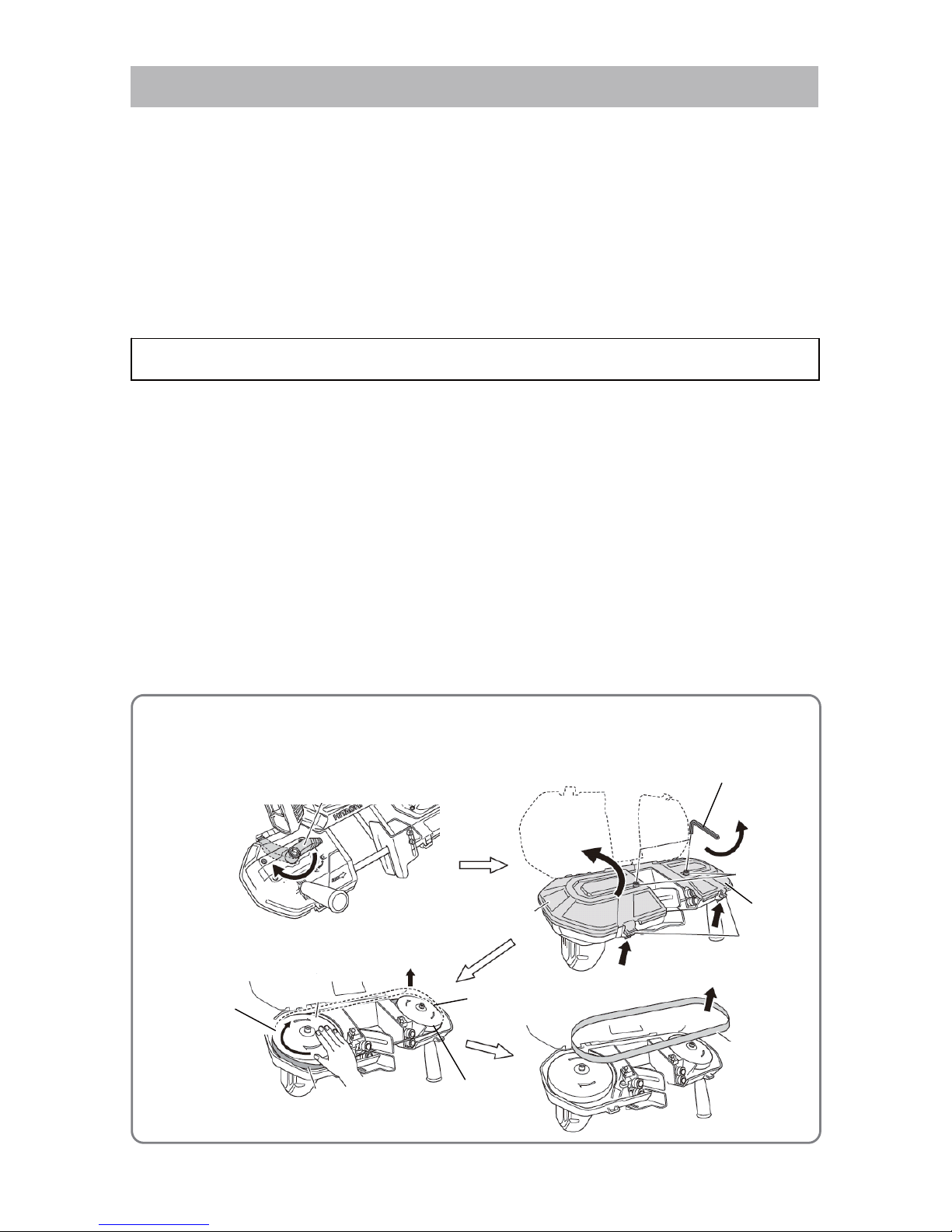
1. Removal of the band saw blade
NOTE: Wear leather gloves before handling the band saw blade to protect your hands from injury
caused by sharp cutting edges. Carefully remove the band saw blade from the main body in
a slow manner to avoid personal injury caused by suddenly ejected band saw blade.
(1) Gently turn the Tension Lever [33] to loosen as shown in the figure below.
(2) Loosen the two Bolts M5 x 16 [80] with the Hex. Bar Wrench 4 mm [501].
NOTE: The Bolt M5 x 16 [80] is retained by the O-ring [77].
(3) Push the claws of Blade Pulley Cover (A) [74] and Blade Pulley Cover (B) [73] to open them.
(4) Slowly turn Blade Pulley (A) [72] or Blade Pulley (B) [71] by hand until the Band Saw Blade [66] comes
out from the top edges of the blade pulleys. Then remove the Band Saw Blade [66].
Disassembly
[33]
Loosen
Claws
[74]
[73]
[72]
[71]
[66]
Top edge of the
blade pulley
The band saw
blade comes out.
REPAIR GUIDE
[501]
[80]
[66]
-2-
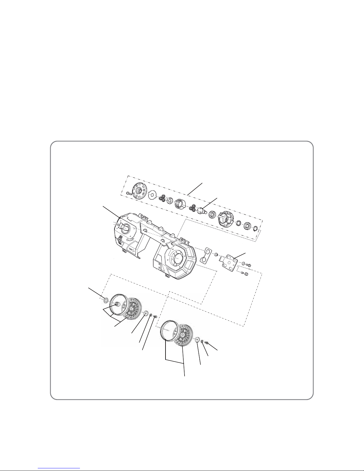
• Removal of blade pulleys (A) and (B) and blade pulley rubbers
2. Removal of blade pulley (A) and blade pulley rubber
(1) Loosen the Bolt M6 x 16 [65] and remove the Spring W a sher M6 [31], Washer (A) [64] and Blade Pulley
(A) [72] from Pulley Shaft (A) [23].
(2) Remove the Blade Pulley Rubber [70] from Blade Pulley (A) [72].
3. Removal of blade pulley (B) and blade pulley rubber
(1) Loosen the Bolt M6 x 16 [65] and remove the Spring W a sher M6 [31], Washer (A) [64] and Blade Pulley
(B) [71] from the Slide Plate [45].
NOTE: Be careful not to lose the Flat Washer [63] that might be attached to the side of the Blade
Pulley (B) [71] when removing Blade Pulley (B) [71].
(2) Remove the Blade Pulley Rubber [70] from Blade Pulley (B) [71].
NOTE: The Needle Bearing [69] is press-fitted in Blade Pulley (B) [71]. Replace the Needle
Bearing [69] with new one if it is damaged.
[65]
[31]
[64]
[72]
[70]
[64]
[31]
[65]
[71]
[70]
[63]
[23]
[45]
[40]
[69]
[28]
-3-
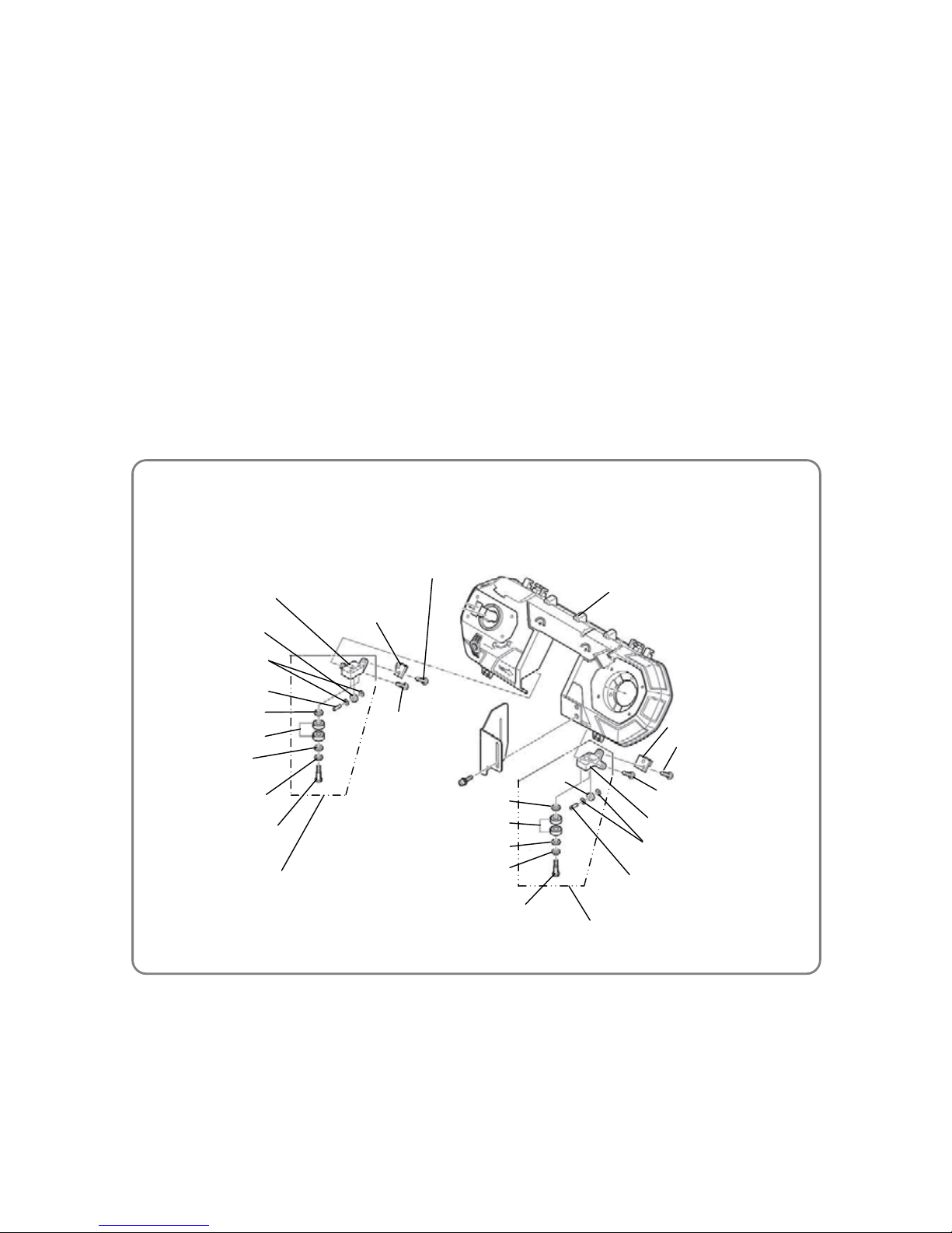
• Disassembly of bearing holder (A) ass'y and bearing holder (B) ass’y
4. Disassembly of bearing holder (A) ass'y
(1) Loosen the Screw D4 x 16 [8] and the Screw D4 x 20 [76]. Remove Cover Holder (A) [79] and Bearing
Holder (A) Ass'y [61] from t he Frame [40].
(2) Loosen the two Bearing Pins (B) [55] with a flat-blade screwdriver and remove the two Spring Washers
M6 [54], two Bolt Washers M6 [53], four Ball Bearings 606VV [52] and two Washers M5 [51] from
Bearing Holder (A) [62].
(3) Remove the Bearing Pin [56], two Bolt Wa shers M4 [57] and Roller 604VV [58] from Bearing Holder (A)
[62].
5. Disassembly of bearing holder (B) ass'y
(1) Loosen the Screw D4 x 16 [8] and Screw D4 x 20 [76]. Remove Cover Holder (B) [75] and Bearing
Holder (B) Ass'y [49] from t he Frame [40].
(2) Loosen two Bearing Pins (B) [55] with a flat-blade screwdriver and remove the two Spring Washers M6
[54], two Bolt Washers M6 [53], four Ball Bearings 606VV [52] and two Washers M5 [51] from Bearing
Holder (B) [50].
(3) Remove the Bearing Pin [56], two Bolt Wa shers M4 [57] and Roller 604VV [58] from Bearing Holder (B)
[50].
[40]
[62]
[61]
[55]
[54]
[53]
[52]
[51]
[49]
[55]
[50]
[54]
[53]
[52]
[51]
[56]
[57]
[58]
[75]
[8]
[76]
[79]
[8]
[76]
[58]
[57]
[56]
-4-
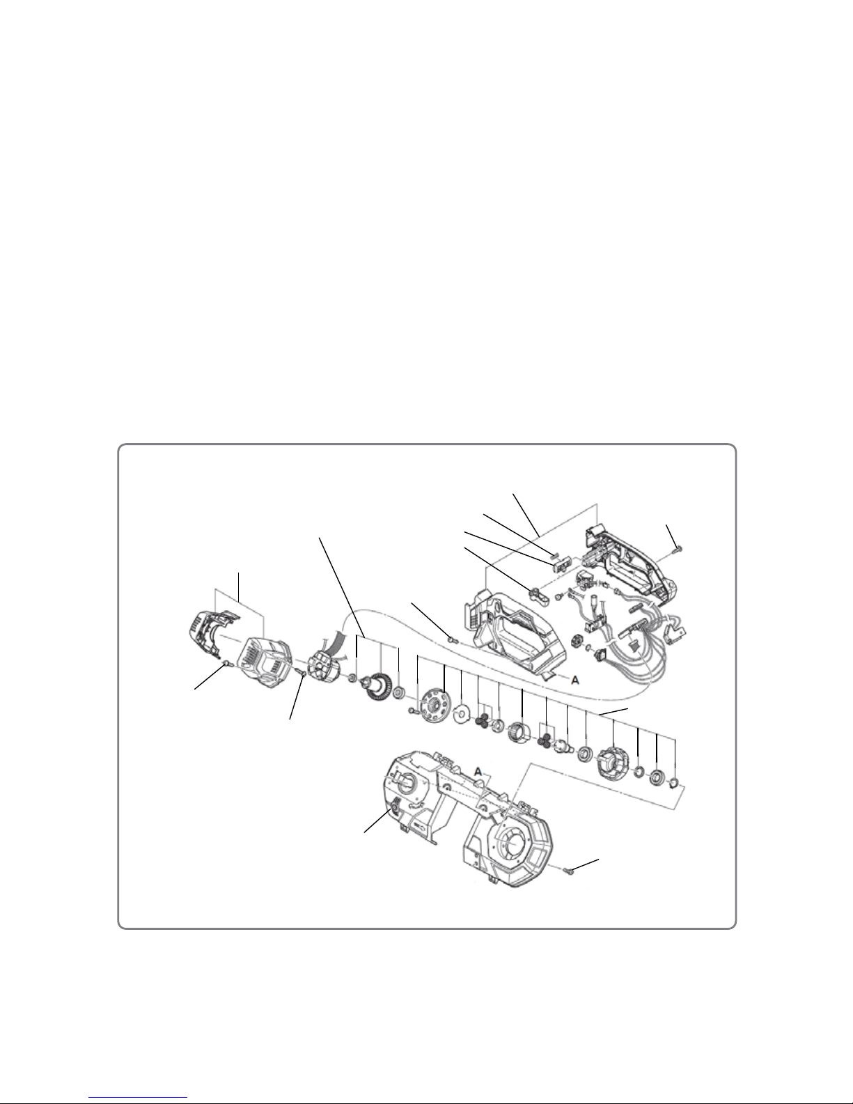
• Disassembly of the handle set and housing set
6. Removal of blade pulley covers (A) and (B)
(1) Remove the two Retaining Rings (E-type) for D3 Shaft [68] with long-nose pliers and pull out the two
Pins D4 [67] from the Frame [40].
(2) Remove Blade Pulley Cover (A) [74] and Blade Pulley Cover (B) [73] from the Frame [40].
(3) Remove the O-rings [77] from Blade Pulley Cover (A) [74] and Blade Pulley Cover (B) [73]. Remove
the Bolt M5 x 16 [80] and Washer M5 [78].
7. Disassembly of the handle set
(1) Loosen and remove the two Screws D4 x 16 [8] at the front of the main body.
(2) Turn the main body upside down. Loosen and remove the eight Screws D4 x 16 [8] and remove the
Handle Set [2] from the Frame [40]. Then disassemble the Handle Set [2].
NOTE: Be careful not to lose the internal p art s (especially the S pring [5] attached to the Knob [6])
when disassembling the Handle Set [2].
8. Disassembly of the housing set
(1) After removal of Blade Pulley (A) [72], loosen and remove the three Screws D4 x 16 [8].
(2) Turn the main body upside down. Loosen and remove the four Screws D4 x 20 [29] and remove the
Housing Set [12] from the Frame [40].
(3) Loosen and remove the four Screws D3 x 20 [35]. Then disassemble the Housing Set [12].
[40]
[2]
[3]
[5]
[6]
[12]
[29]
[28]
[14]
[35]
[8]
[8]
[8]
-5-
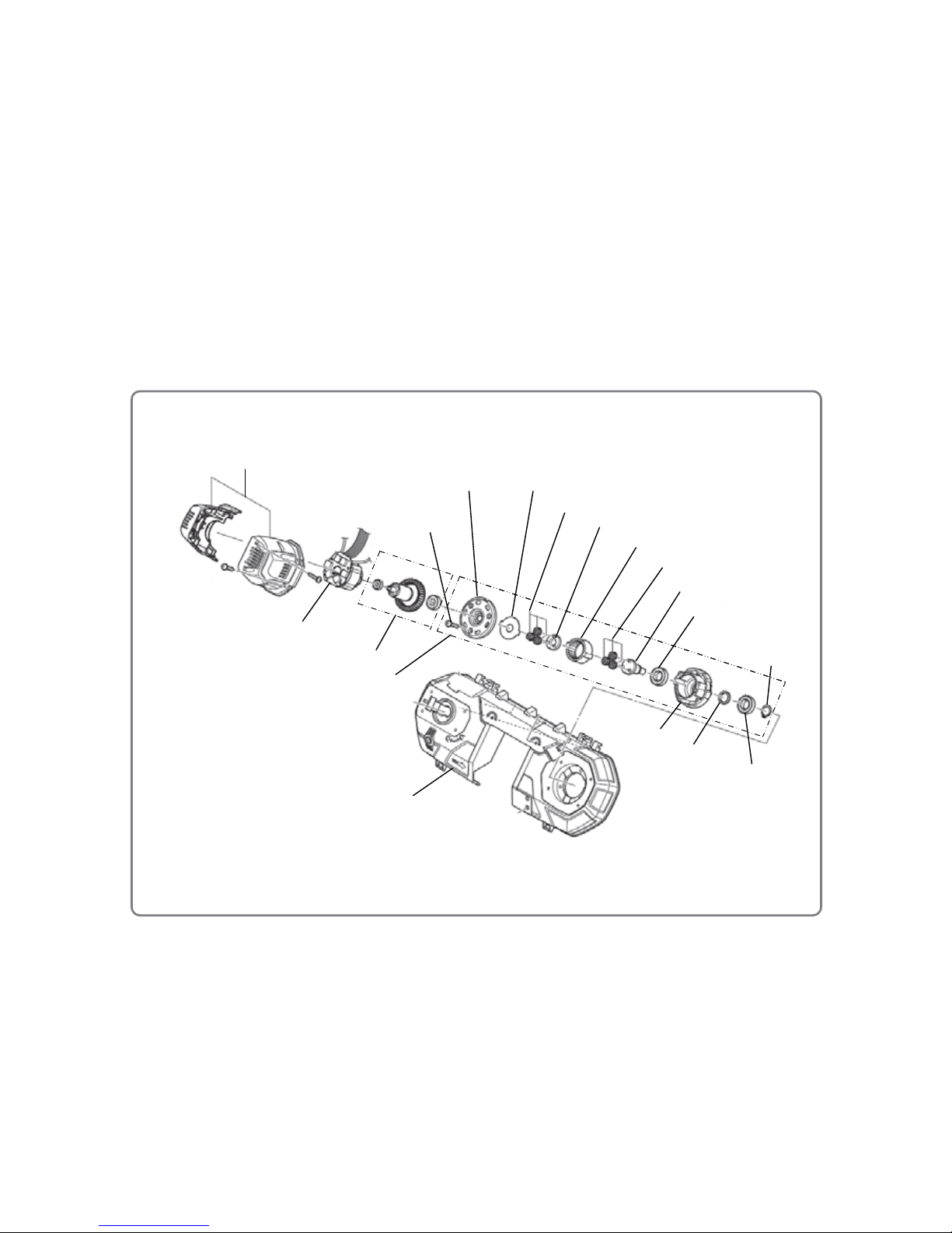
• Disassembly of the rotor pinion set and gear box ass'y
9. Disassembly of the rotor pinion set and gear box ass'y
(1) After disassembly of the Hou sing Set [12], remove the Stator FET PCB Ass'y [13], Rotor Pinion Set [14]
and the Gear Box Ass'y [28] from the Housing Set [12].
(2) Pull out the Rotor Pinion Set [14] from the Gear Box Ass'y [28] and then pull out the Rotor Pinion Set
[14] from the stator of the Stator FET PCB [13].
(3) Loosen the three Screws D4 x 16 [17] inside the Gear Box Ass'y [28] and remove the Gear Case Cover
[18].
(4) Remove the Lock Washer [19], three gears of Planet Gear (A) Set [20], Pinion (B) [21], three gears of
Planet Gear (A) [20] and Ring Gear [22] from the Gear Case [25].
(5) Remove the Retaining Ring for D15 Shaft [27] from Pulley Shaf t (A) [23] by using a retaining ring puller.
(6) Push Pulley Shaft (A) [23] on the retaining ring side to remove it together with the Ball Bearing 6902VV
[24] (on the gear chamber side) and Ring [26] from the Gear Case [25].
(7) Push the Ball Bearing 6902VV [24] (on the retaining ring side) on the gear chamber side of the Gear
Case [25] to remove it.
[12]
[40]
[13]
[14]
[28]
[17]
[18]
[25]
[19]
[20]
[21]
[20]
[22]
[27]
[23]
[24]
[24]
[26]
 Loading...