

Page 1
C 7U • C 8U
Circular Saw
Kreissäge
Scie circulaire
Sega circolare
Cirkelzaagmachine
Sierra circular
Handling instructions
Bedienungsanleitung
Mode d’emploi
Istruzioni per l’uso
Gebruiksaanwijzing
Instrucciones de manejo
Read through carefully and understand these instructions before use.
Diese Anleitung vor Benutzung des Werkzeugs sorgfältig durchlesen und verstehen.
Lire soigneusement et bien assimiler ces instructions avant usage.
Prima dell’uso leggere attentamente e comprendere queste istruzioni.
Deze gebruiksaanwijzing s.v.p. voor gebruik zorgvuldig doorlezen.
Leer cuidadosamente y comprender estas instrucciones antes del uso.
C 7U
Page 2
1
12
34
(A)
4
(B)
5
1
2
3
4
6
5
2
7
8
9
0
2
Max. 3mm
Mas. 3mm
Max. 3mm
Mas. 3mm
2
6
9
Page 3
2
6
(A)
6
(B)
78
910
H
4
I
K
L
B
A
C
E
F
G
2
8
A
8
J
D
*
C7U C8U
J
43 38
Page 4
3
English
Deutsch Farçais
1
2
3
4
5
6
7
8
9
0
A
B
C
D
E
F
G
H
I
J
K
L
M
Lumber Schnittholz Bois
Base Grundplatte Base
Workbench Werkbank Etabli
Saw blade Sägeblatt Lame de la scie
Handle Handgriff Poignée
Knob Stellknopf Bouton
Riving knife Spaltkeil Lame fendue
Hexagonal-head bolt Sechskantkopfschraube Boulon á tête hexagonale
Wing-bolt Fügelschraube Boulon-papillon
Guide Führung Guide
Premarked line Versetzt-Markierung Ligne de repère
Front scale when not inclined Frontskala wenn nicht geneigt Echelle avant quand non incliné
Front scale at 45˚ incline Frontskala bei 45˚ -Neigung Echelle avant quand incliné à 45°
Lock lever Sperrhebel Levier de blocage
Box wrench Steckschlüssel Clef à béquille
Washer (B) Unterlegscheibe (B) Rondelle (B)
Washer (A) Unterlegscheibe (A) Rondelle (A)
Spindle Achse Arbre
Wear limit Verschließgrenze Limite d’usure
No. of carbon brush Nr. der Kohlebürste No. du balai en carbone
Square Winkel Equerre
Slotted set screw Schaftschraube Vis sans fin
Dust collector Staubsauger Collecteur á poussière
11
M
Page 5

4
Italiano
Nederlands Español
1
2
3
4
5
6
7
8
9
0
A
B
C
D
E
F
G
H
I
J
K
L
M
Legno Zaaghout Madera útil
Base Basisplaat Base
Banco di lavoro Werkbank Banco de trabajo
Lame della sega Zaagblad Cuchilla de sierra
Mano Handgreep Mango
Manopola Knop Perilla
Coltello Splijtwig Cuchilla hendidora
Bullone esagonale Zeskantige bout Perno de cabeza exagonal
Bullone a farfalla Vleugelmoer Perno de mariposa
Guida Aanslagplaat Guía
Traccia del taglio Markeerlijn Línea de trazado
Scala frontale non inclinata
Voorste schaal bij
Escala frontal sin inclinación
niet hellend zaagblad
Scala frontale inclinata a 45˚
Voorste schaal bij Escala frontal con 45° de
hellend zaagblad (45°) inclinación
Leva di bloccaggio Palhefboom Palanca de cierre
Chiave fissa a collare Steeksleutel Llave anular
Rondella (B) Onderlegschijf (B) Arandela (B)
Rondella (A) Onderlegschijf (A) Arandela (A)
Asse As Husilio
Limite di usura Slijtagegrens Límite de uso
N. della spazzola di carbone Nr. van de koolborstel No. de carbón de contacto
Squadra Windelhaak Escuadra
Vite senza fine Koploze schroef Vástago
Raccoglipolvere Stof-verzamelaar Colector de polvo
Page 6
5
Symbols
The following show
symbols used for the
machine. Be sure that
you understand their
meaning before use.
Symbole
Die folgenden Symbole
werden für diese
Maschine verwendet.
Achten Sie darauf, diese
vor der Verwendung zu
verstehen.
Read instruction
manual.
Bedienungsanleitung
lesen.
Wear safety glasses.
Gehörschutz tragen.
Wear hearing protection
Gehörschutz tragen.
Lees de handleiding.
Draag een
veiligheidsbril.
Lea el manual de
instrucciones.
Use gafas de seguridad.
Draag
gehoorbescherming.
Utilice protecciones
auriculares.
Symbolen
Hieronder staan
symbolen afgebeeld die
van toepassing zijn op
deze machine. U moet
de betekenis hiervan
begrijpen voor gebruik.
Símbolos
A continuación se
muestran los símbolos
usados para la máquina.
Asegúrese de
comprender su
significado antes del
uso.
Symboles
Les symboles suivants
sont utilisés pour l’outil.
Bien se familiariser avec
leur signification avant
d’utiliser l’outil.
Lire le mode d’emploi.
Leggere il manuale di
istruzioni.
Porter des lunettes de
sécurité.
Indossare occhialoni di
sicurezza.
Porter des protections
anti-bruit.
Indossare i dispositivi di
protezione acustica
Simboli
Di seguito mostriamo i
simboli usati per la
macchina. Assicurarsi di
comprenderne il
significato prima
dell’uso.
Page 7

6
English
GENERAL OPERATIONAL PRECAUTIONS
WARNING! When using electric tools, basic safety
precautions should always be followed to reduce the risk
of fire, electric shock and personal injury, including the
following.
Read all these instructions before operating this product
and save these instructions.
For safe operations:
1. Keep work area clean. Cluttered areas and benches
invite injuries.
2. Consider work area environment. Do not expose
power tools to rain. Do not use power tools in damp
or wet locations. Keep work area well lit.
Do not use power tools where there is risk to cause
fire or explosion.
3. Guard against electric shock. Avoid body contact
with earthed or grounded surfaces. (e.g. pipes,
radiators, ranges, refrigerators).
4. Keep children away. Do not let visitors touch the
tool or extension cord. All visitors should be kept
away from work area.
5. Store idle tools. When not in use, tools should be
stored in a dry, high or locked up place, out of reach
of children.
6. Do not force the tool. It will do the job better and
safer at the rate for which it was intended.
7. Use the right tool. Do not force small tools or
attachments to do the job of a heavy duty tool. Do
not use tools for purposes not intended; for example,
do not use circular saw to cut tree limbs or logs.
8. Dress properly. Do not wear loose clothing or
jewellery, they can be caught in moving parts.
Rubber gloves and non-skid footwear are
recommended when working outdoors. Wear
protecting hair covering to contain long hair.
9. Use eye protection. Also use face or dust mask if
the cutting operation is dusty.
10. Connect dust extraction equipment.
If devices are provided for the connection of dust
extraction and collection facilities ensure these are
connected and properly used.
11. Do not abuse the cord. Never carry the tool by the
cord or yank it to disconnect it from the receptacle.
Keep the cord away from heat, oil and sharp edges.
12. Secure work. Use clamps or a vise to hold the work.
It is safer than using your hand and it frees both
hands to operate tool.
13. Do not overreach. Keep proper footing and balance
at all times.
14. Maintain tools with care. Keep cutting tools sharp
and clean for better and safer performance. Follow
instructions for lubrication and changing
accessories. Inspect tool cords periodically and if
damaged, have it repaired by authorized service
center. Inspect extension cords periodically and
replace, if damaged. Keep handles dry, clean, and
free from oil and grease.
15. Disconnect tools. When not in use, before servicing,
and when changing accessories such as blades, bits
and cutters.
16. Remove adjusting keys and wrenches. Form the
habit of checking to see that keys and adjusting
wrenches are removed from the tool before turning
it on.
17. Avoid unintentional starting. Do not carry a pluggedin tool with a finger on the switch. Ensure switch is
off when plugging in.
18. Use outdoor extension leads. When tool is used
outdoors, use only extension cords intended for
outdoor use.
19. Stay alert. Watch what you are doing. Use common
sense. Do not operate tool when you are tired.
20. Check damaged parts. Before further use of the tool,
a guard or other part that is damaged should be
carefully checked to determine that it will operate
properly and perform its intended function. Check
for alignment of moving parts, free running of
moving parts, breakage of parts, mounting and any
other conditions that may affect its operation. A
guard or other part that is damaged should be
properly repaired or replaced by an authorized
service center unless otherwise indicated in this
handling instructions. Have defective switches
replaced by an authorized service center. Do not use
the tool if the switch does not turn it on and off.
21. Warning
The use of any accessory or attachment, other than
those recommended in this handling instructions,
may present a risk of personal injury.
22. Have your tool repaired by a qualified person.
This electric tool is in accordance with the relevant
safety requirements. Repairs should only be carried
out by qualified persons using original spare parts.
Otherwise this may result in considerable danger
to the user.
PRECAUTIONS ON USING CIRCULAR SAW
1. Do not use saw blades which are deformed or
cracked.
2. Do not use saw blades made of high speed steel.
3. Do not use saw blades which do not comply with
the characteristics specified in these instructions.
4. Do not stop the saw blades by lateral pressure on
the disc.
5. Always keep the saw blades sharp.
6. Ensure that the safety cover moves smoothly and
freely.
7. Never use the circular saw with its safety cover fixed
in the open position.
8. Ensure that the retraction mechanism of the guard
system operates correctly.
9. The saw blades body must be thinner than the riving
knife and the width of cut, or kerf (with teeth set)
must be greater than the thickness of the riving knife.
10. Never operate the circular saw with the saw blade
turned upward or to the side.
11. Ensure that the material is free of foreign matters
such as nails.
12. The riving knife should always be used except when
plunging in the middle of the workpiece.
13. For model C7U, the saw blades range should be
from 185mm to 170mm. For model C8U, the saw
blades range should be from 210mm to 190mm.
Page 8

7
English
STANDARD ACCESSORIES
(1) Saw Blade (mounted on tool) ................................. 1
Dia. 185 mm ................ C7U
Dia. 210 mm ................ C8U
(2) Box Wrench ............................................................... 1
(3) Guide .......................................................................... 1
(4) Wing-bolt ................................................................... 1
Standard accessories are subject to change without
notice.
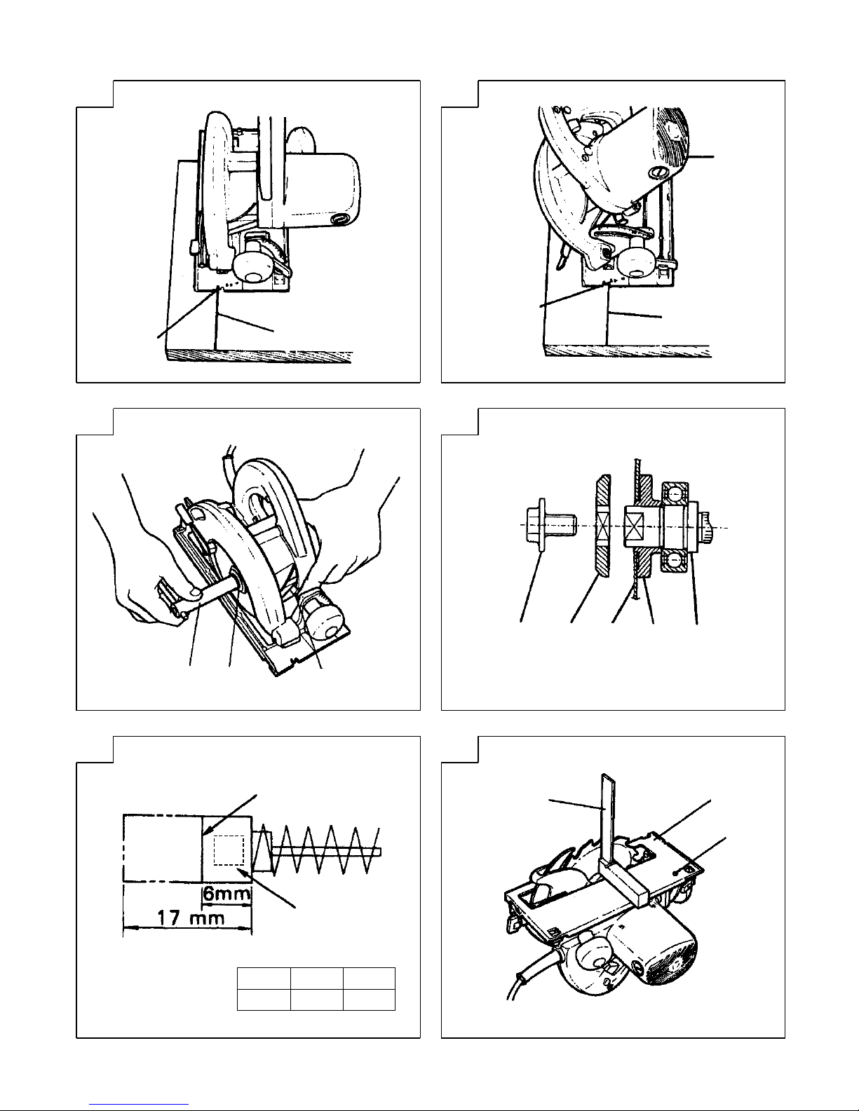
OPTIONAL ACCESSORIES (sold separately)
(1) Dust Collector Set (D) ......................C7U
Dust Collector Set (E) ...................... C8U
Connect the suction hose to collect saw dust with the
vacuum cleaner (see Fig. 11).
(2) Washer (A) ... for 16
mm (Hole dia. of saw blade)
(C7U, C8U)
... for 20 mm (Hole dia. of saw blade)
(C7U)
... for 30 mm (Hole dia. of saw blade)
(C7U, C8U)
Optional accessories are subject to change without notice.
APPLICATION
Cutting various types of wood.
PRIOR TO OPERATION
1. Power source
Ensure that the power source to be utilized conforms
to the power requirements specified on the product
nameplate.
2. Power switch
Ensure that the power switch is in the OFF position. If
the plug is connected to a receptacle while the power
switch is in the ON position, the power tool will start
operating immediately, which could cause a serious
accident.
3. Extension cord
When the work area is removed from the power
source, use an extension cord of sufficient thickness
and rated capacity. The extension cord should be kept
as short as practicable.
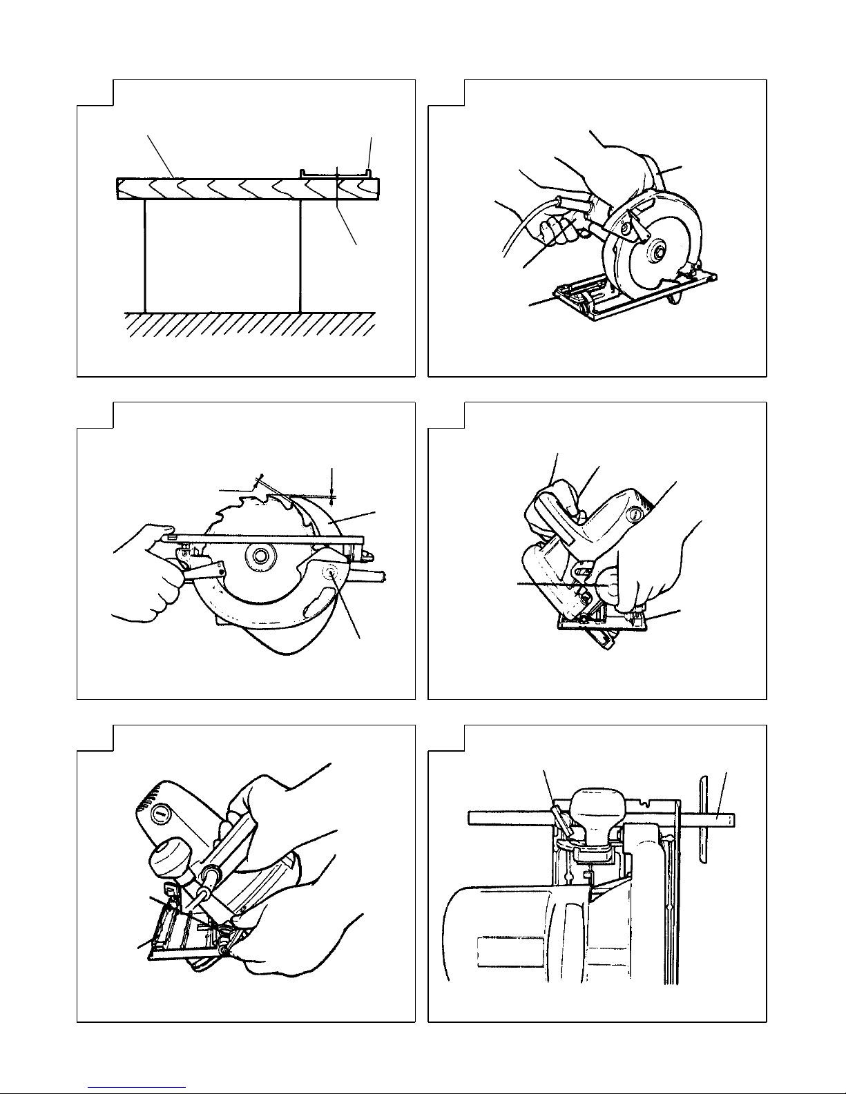
4. Prepare a wooden workbench (Fig. 1)
Since the saw blade will extend beyond the lower
surface of the lumber, place the lumber on a
workbench when cutting. If a square block is utilized
as a workbench, select level ground to ensure it is
properly stabilized. An unstable workbench will result
in hazardous operation.
SPECIFICATIONS
CAUTION
To avoid possible accident, always ensure that the portion
of lumber remaining after cutting is securely anchored
or held in position.
ADJUSTING THE SAW PRIOR TO USE
1. Adjusting the cutting depth
As shown in Fig. 2, hold the handle with one hand
while loosening the knob with the other.
The cutting depth can be adjusted by moving the base
to the desired position. In such manner adjust the
cutting depth and then securely retighten the knob.
2. Adjusting the riving knife
Loosen the hexagonal – head bolt used to clamp the
riving knife, adjust the riving knife to the position
shown in Fig. 3 and securely retighten the bolt. After
adjustment, ensure that riving knife moves in
accordance with the adjusted cutting depth.
3. Adjusting the angle of inclination
As shown in Fig. 4 (A), Fig. 4 (B) by loosening the
knob on the incline gauge and the wing-bolt on the
base, the saw blade may be inclined to a maximum
angle of 45° in relation to the base. After having
completed the adjustment, reconfirm that the knob
and the wing bolt are firmly tightened.
4. Regulating the guide (Fig. 5)
The cutting position can be regulated by moving the
guide to the left or right after loosening its wingbolt.
The guide may be mounted on either the right or left
side of the tool.
CUTTING PROCEDURES
1. Place the saw body (base) on the lumber, and align
the marked off line with the saw blade by use of the
front scale. When the saw blade is not inclined, the
right-hand side is the reference (Fig. 6 (A)); when the
saw blade is inclined (45°), the left-hand side marked
“45” on the base) is the reference (Fig. 6 (B)).
2. Ensure that the switch is turned to the ON position
before the saw blade comes in contact with the
lumber. The switch is turned ON when the trigger is
squeezed; and OFF when the trigger is released.
3. Moving the saw straight at a constant speed will
produce optimum cutting.
CAUTIONS
䡬 Before starting to saw, ensure that the saw blade has
reached full speed revolution.
䡬 Should the saw blade be stopped or made an
abnormal noise during operation, turn off the switch
immediately.
䡬 Always take care in preventing the power cord from
coming near the revolving saw blade.
* Be sure to check the nameplate on product as it is subject to change by areas.
Model C7U C8U
Voltage (by areas)*
(110V, 220V, 230V, 240V)
Cutting Depth 90° 65 mm 75 mm
45° 47 mm 57 mm
Power
Input*
1150W* 1400W*
No-Load Speed
5000 min
–1
5000 min
–1
Weight (without cord) 4.0 kg 5.6 kg
Page 9

8
English
MOUNTING AND DISMOUNTING THE SAW
BLADE
CAUTION
To avoid serious accident, ensure the switch is in the OFF
position, and the power source is disconnected.
1. Dismounting the saw blade
(1) Set the cutting volume at maximum, and place the
Circular Saw as shown in Fig. 7.
(2) Depress the lock lever, lock the spindle, and remove
the hexagonal-head bolt with the box wrench.
(3) While holding the safety cover lever to keep the safety
cover fully retracted into the saw cover, remove the
saw blade.
2. Mounting the Saw Blade:
(1) Thoroughly remove any sawdust which has
accumulated on the spindle, bolt and washers.
(2) As shown in Fig. 8, the side of Washer (A) with a
projected center the same diameter as the inner
diameter of the saw blade and the concave side of
Washer (B) must be fitted to the saw blade sides.
* Washer (A) is supplied for 3 types of saw blades
with the hole diameters of 16 mm, 20 mm and 30
mm. (When buying the Circular Saw, one type of
washer (A) is spplied.)
In case the hole diameter of your saw blade does
not correspond to that of washer (A), please
contact the shop where you purchased the Circular
Saw.
(3) To assure proper rotation direction of the saw blade,
the arrow direction on the saw blade must coincide
with the arrow direction on the saw cover.
(4) Using the fingers, tighten the hexagonal-head bolt
retaining the saw blade as much as possible. Then
depress the lock lever, lock the spindle, and
thoroughly tighten the bolt.
CAUTION
After having attached the saw blade, reconfirm that the
lock lever is firmly secured in the prescribed position.
MAINTENANCE AND INSPECTION
1. Inspecting the saw blade:
Since use of a dull saw blade will degrade efficiency
and cause possible motor malfunction, sharpen or
replace the saw blade as soon as abrasion is noted.
2. Inspecting the mounting screws:
Regularly inspect all mounting screws and ensure that
they are properly tightened. Should any of the screws
be loose, retighten them immediately. Failure to do
so could result in serious hazard.
3. Inspecting the carbon brushes (Fig. 9)
The motor employs carbon brushes which are
consumable parts. Since an excessively worn carbon
brush can result in motor trouble, replace the carbon
brushes with new ones having the same carbon brush
No. shown in the figure when it becomes worn to or
near the “wear limit”. In addition, always keep carbon
brushes clean and ensue that they slide freely within
the brush holders.
4. Replacing carbon brushes:
Disassemble the brush caps with a slotted-head
screwdriver. The carbon brushes can then be easily
removed.
5. Maintenance of the motor
The motor unit winding is the very “heart” of the
power tool.
Exercise due care to ensure the winding does not
become damaged and/or wet with oil or water.
6. Adjusting the base and saw blade to maintain
perpendicularity:
The angle between the base and the saw blade has
been adjusted to 90°, however should this
perpendicularity be lost for some reason, adjust in
the following manner:
(1) Turn the base face up (Fig. 10) and loosen the knob
and wing-bolt (Fig. 4 (A), Fig. 4 (B)).
(2) Apply a square to the base and the saw blade and
turning the slotted set screw with a slotted-head
screwdriver, shift the position of the base to produce
the desired right angle.
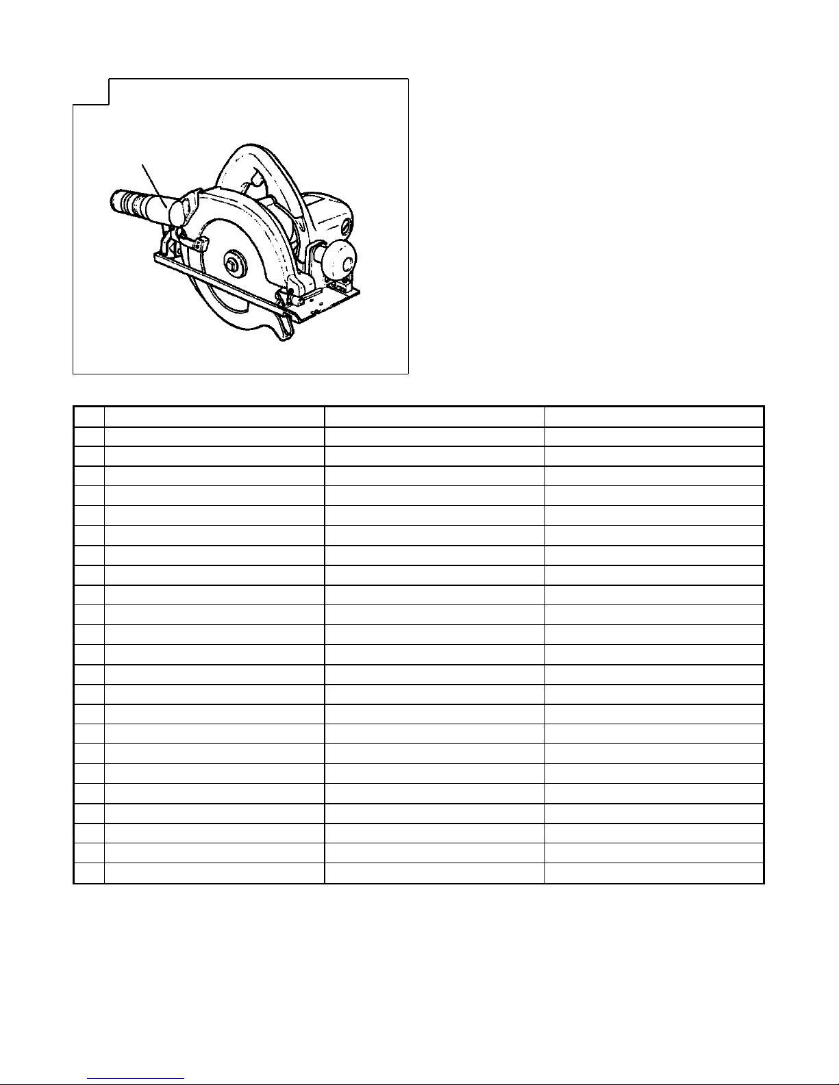
7. Service parts list
A: Item No.
B: Code No.
C: No. Used
D: Remarks
CAUTION
Repair, modification and inspection of Hitachi Power
Tools must be carried out by an Hitachi Authorized
Service Center.
This Parts List will be helpful if presented with the
tool to the Hitachi Authorized Service Center when
requesting repair or other maintenance.
In the operation and maintenance of power tools, the
safety regulations and standards prescribed in each
country must be observed.
MODIFICATIONS
Hitachi Power Tools are constantly being improved
and modified to incorporate the latest technological
advancements.
Accordingly, some parts (i.e. code numbers and/or
design) may be changed without prior notice.
NOTE
Due to HITACHI’s continuing program of research and
development, the specifications herein are subject to
change without prior notice.
IMPORTANT
Correct connection of the plug
The wires of the main lead are coloured in accordance
with the following code:
Blue: – Neutral
Brown: – Live
As the colours of the wires in the main lead of this tool
may not correspond with the coloured markings
identifying the terminals in your plug proceed as follows:
The wire coloured blue must be connected to the terminal
marked with the letter N or coloured black.
The wire coloured brown must be connected to the
terminal marked with the letter L or coloured red.
Neither core must be connected to the earth terminal.
NOTE
This requirement is provided according to BRITISH
STANDARD 2769: 1984.
Therefore, the letter code and colour code may not be
applicable to other markets except The United Kingdom.
Page 10

9
English
Information concerning airborne noise and vibration
The measured values were determined according to
EN50144.
The typical A-weighted sound pressure level: 95 dB (A)
The typical A-weighted sound power level: 108 dB (A)
Wear ear protection.
The typical weighted root mean square acceleration value
does not exceed 2.5 m/s2.
䢇 Information about power supply system of nominal
voltage 230 V~
Under unfavorable mains conditions, this power tool may
cause
transient voltage drops or interfering voltage
fluctuations
.
This power tool is intended for the connection to a power
supply system with a maximum permissible system
impedance Z
MAX
of 0.47 (C7U), 0.40 (C8U) Ohm at the
interface point (power service box) of the user's supply.
The user has to ensure that this power tool is connected
only to a power supply system which fulfills the
requirement above.
If necessary, the user can ask the public power supply
company for the system impedance at the interface point.
Page 11

10
Deutsch
ALLGEMEINE VORSICHTSMASSNAHMEN
WARNUNG! Bei der Verwendung von Elektrowerkzeugen
müssen immer die grundlegenden Vorsichtsmaßnahmen
befolgt werden, um das Risiko von Feuer, elektrischem
Schlag und persönlicher Verletzung und den
nachfolgenden Punkten zu vermeiden.
Lesen Sie diese Anweisungen völlig, bevor Sie dieses
Erzeugnis verwenden, und bewahren Sie diese
Anweisungen auf.
Für sicheren Betrieb:
1. Der Arbeitsplatz sollte sauber gehalten werden.
Unaufgeräumte Arbeitsplätze und Werkbänke
erhöhen die Unfallgefahr.
2. Die Betriebsbedingungen beachten.
Elektrowerkzeuge sollten nicht dem Regen
ausgesetzt werden.
Ebenfalls sollten Sie nicht an feuchten oder nassen
Plätzen gebraucht werden.
Der Arbeitsplatz sollte gut beleuchtet sein.
Verwenden Sie Elektrowerkzeuge nicht an Orten, an
denen die Gefahr von Feuer oder Explosion besteht.
3. Schutzmaß nahmen gegen elektrische Schläge
treffen. Darauf achten, daß das Gehäuse nicht in
Kontakt mit geerdeten Flachen kommt, z. (z.B. Rohre,
Radiatoren, Elektroherde, Kühlschränke).
4. Kinder sollten vom Gerät ferngehalten werden.
Vermeiden, daß andere Personen mit dem
Werkzeung oder Verlängerungskabel in Kontakt
kommen.
5. Nicht benutzte Werkzeuge sollten sicher aufbewahrt
werden. Sie sollten an einem trockenen und
verschließbaren Ort aufbewahrt werden, damit
Kinder sie nicht in die Hände bekommen.
6. Werkzeuge sollten nicht mit übermäßiger Gewalt
verwendet werden. Ihre Leistung ist besser und
sicherer, wenn sie mit der vorgeschriebenen
Geschwindigkeit verwendet werden.
7. Nur die korrekten Werkzeuge verwenden. Niemals
ein kleineres Werkzeug oder Zusatzgerat für
Arbeiten verwenden, die Hochleistungsgerate
erfordern. Nur Werkzeuge verwenden, die dem
Verwendungszweck entsprechen, d.h. niemals eine
Kreissäge zum Sägen von Ästen oder
Baumstämmen verwenden.
8. Die richtige Kleidung tragen. Keine lose Kleidung
oder Schmuck tragen, da sich lose Kleidungsstücke
in den bewegenden Teilen verfangen kònnen. Bei
Arbeiten im Freien sollten Gummihandschuhe und
rutschfeste Schuhe getragen werden.
9. Es sollte eine Sicherheitsbrille getragen werden. Bei
Arbeiten mit Staubentwicklung sollte eine
Gesichtsoder Staubmaske getragen werden.
10. Schließen Sie eine Staubabsaugvorrichtung an.
Wenn Vorrichtungen für den Anschluß von
Staubabsaug- und -sammelvorrichtungen
vorhanden sind, so stellen Sie sicher, daß diese
angeschlossen sind und richtig verwendet werden.
11. Niemals das Kabel mißbrauchen. Ein Werkzeug
niemals am Kabel tragen oder bei Abtrennung von
der Steckdose das Kabel harausreißen. Das Kabel
sollte gegen Hitze, Öl und scharfe Kanten geschützt
werden.
12. Den Arbeitsplatz gut absichern. Zwingen oder einen
Schraubstock zur Befestigung des Werkstücks
verwenden. Das ist sicherer als die Benutzung der
Hände und macht beide Hände zur Bedienung des
Werkzeugs frei.
13. Sich niemals weit überbeugen. Immer einen festen
Stand und ein sicheres Gleichgewicht bewahren.
14. Die Werkzeuge sollten sorgfältig behandelt werden.
Für einen einwandfreien und sicheren Betrieb sollten
sie stets scharf sein und saubergehalten werden. Die
Anleitungen für schmierung und Austausch des
Zuehörs unbedingt einhalten. Die Kabel der Geräte
regelmäßig überprüfen und bei Beschädigung durch
eine autorisierte Kundendienststelle reparieren
lassen.
Ebenfalls die Verlägerungskabel regelmäßig
überprüfen und bei Beschadigung auswechseln.
Die Handgriffe sollten stets trocken und sauber sein,
sowie keine Ol- oder Schmierfett stellen aufweisen.
15. Werkzeuge vom Netz trennen, wenn sie nicht
benutzt werden, vor Wartungsarbeiten und beim
Austausch von Zubehörteilen wie z.B. Blätter, Bohrer
und Messer.
16. Alle Stellkeile und Schraubenschlüssel entfernen.
Vor Einschaltung des Gerätes darauf achten, daß
alle Stellkeile und Schraubenschlüssel entfernt
worden sind.
17. Ein unbeabsichtigtes Einschalten sollte vermieden
werden. Niemals ein angeschlossenes Werkzeug mit
dem Finger am Schalter tragen. Vor Anschluß
überprüfen, ob das Gerät ausgeschaltet ist.
18. Im Freien ein Verlängerungskabel verwenden. Nur
ein Verlängerungskabel verwenden, das für die
Verwendung im Freien markiert ist.
19. Den Arbeitsvorgang immer unter Kontrolle haben.
Das Gerät niemals in einem abgespannten Zustand
verwenden.
20. Beschädigte Teile überprüfen. Vor Benutzung des
Werkzeugs sollten beschädigte Teile oder
Schutzvorrichtungen sorgfältig überprüft werden,
um festzustellen, ob sie einwandfrei funktionieren
und die vorgesehene Funktion erfüllen, Ausrichtung,
Verbindungen sowie Anbringung sich bewegender
Teile überprüfen. Ebenfalls uberprufen, ob Teile
gebrochen sind. Teile oder Schutzvorrichtungen, die
beschädigt sind, sollten, wenn in dieser
Bedienungsanleitung nichts anderes erwähnt ist,
durch eine autorisierte Kundendienststelle ausge
wechselt oder repariert werden. Dasselbe gilt für
defekte Schalter.
Wenn sich das Werkzeug nicht mit dem Schalter
einoder ausschalten läßt, sollte das Werkzeug nicht
verwendet werden.
21. Warnung
Die Verwendung von anderem Zubehör oder
anderen Zusätzen als in dieser Bedienungsanleitung
empfohlen kann das Risiko einer Körperverletzung
einschließen.
22. Lassen Sie Ihr Werkzeug durch qualifiziertes Personal
reparieren. Dieses Elektrowerkzeug entspricht den
zutreffenden Sicherheitsanforderungen. Reparaturen
sollten nur von qualifiziertem Personal unter
Verwendung von Originalersatzteilen durchgeführt
werden, da sonst beträchtliche Gefahr für den
Benutzer auftreten kann.
VORSICHTSMASSNAHMEN BEI DER
BENUTZUNG DER KREISSÄGE
1. Nicht verbogene oder gerissene Sägeblätter
verwenden.
2. Nicht Sägeblätter aus getempertem Stahl
verwenden.
3. Nicht Sägeblätter verwenden, die nicht mit den in
dieser Anweisung gegebenen Regeln
übereinstimmen.
4. Nicht die Sägeblätter durch seitlichen Druck auf die
Scheibe stoppen.
5. Die Sägeblätter immer scharf halten.
6. Die Schutzhaube muß sich leicht und frei bewegen.
7. Die Kreissäge nie benutzen, wenn die Schutzhaube
in offener Position arretiert ist.
8. Immer sicherstellen, daß der Rückzugmechanismus
des Schutzsystems richtig arbeitet.
Page 12

11
Deutsch
9. Die Sägblätter müssen dünner sein als der Spaltkeil
und die Breite des Schnittes, der Kerbschnitt (mit
eingesetzten Zähnen) muß größer sein als die Stärke
des Spaltkeils.
10. Die Kreissäge nie mit schrägstehendem oder seitlich
stehendem Sägeblatt einsetzen.
TECHNISCHE DATEN
STANDARDZUBEHÖR
(1) Sägeblatt (am Werkzeug befestigt) ........................ 1
Durchmesser 185 mm .............. C7U
Durchmesser 210 mm .............. C8U
(2) Steckschlüssel ........................................................... 1
(3) Parallelanschlag ........................................................ 1
(4) Flügelschraube .......................................................... 1
Das Standardzubehör kann ohne vorherige
Bekanntmachung jederzeit geändert werden.
SONDERZUBEHÖR (separat zu beziehen)
(1) Staubfangsatz (D) ......................................... C7U
Staubfangsatz (E) .......................................... C8U
Schließen Sie den Saugschlauch zum Absaugen von
Staub an dem Staubsauger an (siehe Abb. 11).
(2) Unterlegscheibe (A)
...... für 16 mm (Lochdurch messern des Sägeblattes)
(C7U, C8U)
...... für 20 mm (Lochdurch messern des Sägeblattes)
(C7U)
...... für 30 mm (Lochdurch messern des Sägeblattes)
(C7U, C8U)
Das Sonderzubehör kann ohne vorherige
Bekanntmachung jederzeit geändert werden.
ANWENDUNG
Schneiden verschiedener Holzarten.
VOR INBETRIEBNAHME
1. Netzspannung
Prüfen, daß die zu verwendende Netzspannung der
Angabe auf dem Typenschild entspricht.
2. Netzschalter
Prüfen, daß der Netzschalter auf “AUS” steht. Wenn
der Stecker an das Netz angeschlossen wird, während
der Schalter auf “EIN” steht, beginnt das Werkzeug
sofort zu laufen, was gefährlich ist.
3. Verlängerungskabel
Wenn der Arbeitsbereich nicht in der Nähe des
Netzanschlusses liegt, ist ein Verlängerungskabel
ausreichenden Querschnitts und ausreichender
Nennleistung zu verwenden. Das Verlängerungskabel
sollte so kurz wie möglich gehalten werden.
4. Schaffung einer hölzernen Werkbank (Abb. 1)
Da das Sägeblatt über die Unterkante des
Schnittholzes hinausragt, wird das Schnittholz beim
Schneiden auf eine Werkbank gelegt. Wenn ein
Holzklotz als Untergestell verwendet wird, ist ein
ebener Untergrund zu wählen, damit dieser fest liegt.
Ein nichtstabiles Untergestell ist gefährlich.
ACHTUNG
Um einen möglichen Unfall zu vermeiden, ist immer
darauf zu achten, daß der nach dem Schneiden
verbleibende Teil des geschnittenen Holzes gut verankert
ist oder in Position gehalten wird.
EINSTELLUNG VOR DEM SCHNEIDEN
1. Einstellen der Schnittiefe
Mit der einen Hand den Stellknopf lösen und dabei,
wie in Abb. 2 dargestellt, mit der anderen Hand das
Werkzeug am Handgriff halten. Die Kerbentiefe kann
durch Ausrichten der Auflage in die gewünschte
Position eingestellt werden. Die Schnittiefe auf diese
Weise einstellen und anschließend den Stellknopf
wieder festziehen.
2. Einstellen des Spaltkeils
Die Sechskantmutter, mit der der Spaltkeil
festgeklemmt ist, wird gelockert, der Spaltkeil in die
in Abb. 3 gezeigte Position gebracht und die Mutter
fest angezogen. Nach der Einstellung ist zu prüfen,
daß sich der Spaltkeil entsprechend der eingestellten
Schnittiefe bewegt.
3. Einstellen des Schrägwinkels
Durch Lösen der Flügelschrauben der Schräglehre
kann, wie in Abb. 4 (A) und Abb. 4 (B) dargestellt, das
Sägeblatt bis zu maximal 45° zur Grundplatte gekippt
werden. Nach der Einstellung prüfen, ob der
Stellknopf und die Flügelschrauben fest angezogen
sind.
Modell C7U C8U
Spannung (je nach Gebiet)* (110V, 220V, 230V, 240V)
Schnittiefe
90° 65 mm 75 mm
45° 47 mm 57 mm
Leistungsaufnahme* 1150W* 1400W*
Leeraufdrehzahl 5000 min
–1
5000 min
–1
Gewicht (ohne Kabel) 4,0 kg 5,6 kg
*Vergessen Sie nicht, die Produktangaben auf dem Typenschild zu überprüfen, da sich diese je nach Verkaufsgebiet
ändern.
11. Immer darauf achten, daß das Werkstück keine
fremden Gegenstände wie Nägel enthält.
12. Der Spaltkeil soll immer verwendet werden,
ausgenommen wenn in die Mitte des Werkstücks
gesenkt wird.
13. Für Modell C7U soll der Sägeblattbereich von 185
mm bis 170 mm reichen.
Für Modell C8U soll der Sägeblattbereich von 210
mm bis 190 mm reichen.
Page 13

12
Deutsch
4. Einstellung des Parallelanschlags (Abb. 5)
Die Schniedposition kann durch Verstellen des
Parallelanschlags nach rechts oder links nach
Losdrehen der Flügelschraube verstellt werden. Der
Parallelanschlag kann an der rechten oder an der
linken Seite des Werkzeugs angebracht sein.
SCHNEIDEVERFAHREN
1. Das Sägegehäuse (die Grundplatte) wird auf das
Schnittholz gesetzt und das Sägeblatt mit der
angezeichneten Linie mit Hilfe der vorderen Skala
ausgerichtet. Wenn das Sägeblatt nicht geneigt ist,
ist die rechte Seite zu benutzen (Abb. 6 (A)), wenn
das Sägeblatt geneigt ist (45°), ist die linke Seite zu
benutzen (Abb. 6 (B)).
2. Es ist darauf zu achten, daß der Schalter auf “EIN”
geschaltet ist, ehe das Sägeblatt mit dem Schnittholz
in Berührung kommt. Der Schalter wird eingeschaltet,
wenn der Drücker eingedrückt wird und ausgeschaltet,
wenn der Drücker losgelassen wird.
3. Um einen sauberen Schnitt zu erzielen, das Sägeblatt
mit gleichbleibender Geschwindigkeit nach vorn
bewegen.
ACHTUNG
䡬 Ehe mit dem Sägen begonnen wird, muß das
Sägeblatt die volle Umdrehungsgeschwindigkeit
erricht haben.
䡬 Bleibt das Sägeblatt hängen oder macht es ein
ungewöhnliches Geräusch während des Schneidens,
ist der Schalter sofort auszuschalten.
䡬 Das Anschlußkabel darf niemals in die Nähe des
laufenden Sägeblattes kommen.
ANBRINGEN UND ENTFERNEN DES
SÄGEBLATTES
ACHTUNG
Als Vorbeugemaßnahme gegen Unfälle ist darauf zu
achten, daß der Schalter auf “AUS” steht und der
Netzanschluß unterbrochen ist.
1. Ausbauen des Sägeblattes
(1) Die Grundplatte auf maximale Schnittiefe einstellen
und die Kreissäge wie in Abb. 7 gezeigt ausrichten.
(2) Den Sicherungshebel herunterdrücken, die Achse
verriegeln und die Sechskantkopfschraube mit dem
Steckschlüssel festziehen.
(3) Der Hebel des Schutzdeckels wird festgehalten, so daß
der Schutzdeckel ganz in den Sägeschutz geklappt ist,
dann wird das Sägeblatt herausgenommen.
2. Einbauen des Sägeblattes
(1) Sä gemehl von Achse und Unterlegscheiben
abwischen.
(2) Gemäß Abb. 8 muß die Seite der Unterlegscheibe (A)
mit einem vorstehenden Mittelstück mit demselben
Durchmesser wie der Innendurchmesser des
Sä geblattes und die konkave Seite der
Unterlegscheibe (B) an beiden Seiten des Sägeblattes
angebracht werden.
* Im Lieferunfang ist eine Unteriegscheibe (A) für
die 3 Sägeblattypen mit den Lochdurchmessern
16 mm, 20 mm und 30 mm enthalten.
(Beim Kauf der Kreissäge wird ein
Unterlegscheibentyp (A) mitgeliefert).
Falls der Lochdurchmesser Ihres Sägeblattes nicht
der Unterlegscheibengröße (A) entspricht, wenden
Sie sich bitte an den Fachhandel, bei dem die
Kreissäge gekauft wurde.
(3) Das Sägeblatt so montieren, daß der Pfeil auf dem
Sägeblatt auf den Pfeil auf dem Sägeblattdeckel
ausgerichtet ist.
(4) Die das Sägeblatt haltende Sechskantkopfschraube
von Hand so fest wie möglich anziehen. Anschließend
den Sicherungshebel herunterdrücken, die Achse
verriegeln und die Schraube fest anziehen.
VORSICHT
Nach dem Anbringen des neuen Sägeblattes sich
vergewissern, daß der Sperrhebel in die vorgeschriebene
Position gestellt ist.
WARTUNG UND INSPEKTION
1. Inspektion des Sägeblattes:
Da durch ein stumpfes Sägeblatt die Leistung
abnimmt und ein mögliches Versagen des Motors
verursacht wird, muß das Sägeblatt geschärft oder
ersetzt werden, sobald Verschleiß festgestellt wird.
2. Inspektion der Befestigungsschrauben:
Alle Befestigungsschrauben werden regelmäßig
inspiziert und geprüft, ob sie gut angezogen sind.
Wenn sich eine der Schrauben lockert, muß sie sofort
wieder angezogen werden. Geschieht das nicht, kann
das zu erheblichen Gefahren führen.
3. Inspektion der Kohlebürsten: (Abb. 9)
Im Motor sind Kohlebürsten verwendet, die
Verbrauchsteile sind. Übermaß ig abgenutzte
Kohlenbürsten führen zu Motor, problemen.
Deshalb wird eine Kohlebürste durch eine neue
ersetzt, die dieselbe Nummber trägt wie auf der
Abbildung gezeigt, wenn sie teilweise oder ganz
verbraucht ist. Darüber hinaus mü ssen die
Kohlebürsten immer sauber gehalten werden und
müssen sich in der Halterung frei bewegen können.
4. Austausch einer Kohlebürste:
Der Bürstendeckel wird mit einem Steckschlüssel
abmontiert. Dann kann die Kohlebürste leicht entfernt
werden.
5. Wartung des Motors:
Die Motorwicklung ist das “Herz” des
Elektrowerkzeugs. Daher ist besonders sorgfältig
darauf zu achten, daß die Wicklung nicht beschädigt
wird und/oder mit Öl oder Wasser in Berührung
kommt.
6. Einstellen der Rechtwinkligkeit zwischen Auflage und
Sägeblatt:
Ursprünglich wurde der Winkel zwischen Sägeblatt
und Auflage auf einen Winkel von 90° eingestellt.
Geht die Rechtwinkligkeit jedoch verloren, in
folgender Reihenfolge berichtigen:
(1) Die Grundplatte nach oben weisend umdrehen (Abb.
10) und anschließend den Stllknopf und die
Flügelschraube lösen (Abb. 4 (A), Abb. 4 (B)).
(2) Einen Winkel an Auflage und Sägeblatt anlegen und
die Schaftschraube mit einem Treiber drehen, um so
die Auflage zu verschieben. Auflage und Sägeblatt so
einstellen, daeine Rechtwinkligkeit hergestellt wird.
7. Liste der Wartungsteile
A: Punkt Nr.
B: Code Nr.
C: Verwendete Anzahl
D: Bemerkungen
Page 14

13
Deutsch
ACHTUNG
Reparatur, Modifikation und Inspektion von HitachiElektrowerkzeugen müssen durch ein autorisiertes
Hitachi-Kundendienstzentrum durchgeführt werden.
Diese Teileliste ist hilfreich, wenn sie dem
autorisierten Hitachi-Kundendienstzentrum
zusammen mit dem Werkzeug für Reparatur oder
Wartung ausgehändigt wird.
Bei Betrieb und Wartung von Elektrowerkzeugen
müssen die Sicherheitsvorschriften und Normen
beachtet werden.
MODIFIKATIONEN
Hitachi-Elektrowerkzeuge werden fortwährend
verbessert und modifiziert, um die neuesten
technischen Fortschritte einzubauen.
Dementsprechend ist es möglich, daß einige Teile (z.B.
Codenummern bzw. Entwurf) ohne vorherige
Benachrichtigung geändert werden.
ANMERKUNG
Aufgrund des ständigen Forschungs- und
Entwicklungsprogramms von HITACHI sind Änderungen
der hierin gemachten technischen Angaben nicht
ausgeschlossen.
Information über Betriebslärm und Vibration
Die Meßwerte wurden entsprechend EN50144 bestimmt.
Der typische A-gewichtete Schalldruckt ist 95 dB (A).
Der typische A-gewichtete Schalleistungspegel ist 108 dB
(A).
Bei der Arbeit immer einen Ohrenschutz tragen.
Der typische gewichtete Effektiv-Beschleunigungswert
überschreitet nicht 2,5 m/s2.
䢇 Informationen zum Stromversorgungssystem mit
einer Nennspannung von 230 V oder mehr
Unter ungünstigen Netzbedingungen kann dieses
Elektrowerkzeug
vorübergehenden Spannungsabfall
oder
störende Spannungsschwankungen
verursachen.
Dieses Elektrowerkzeug ist vorgesehen für den Anschluss
an ein Stromversorgungssystem mit einer maximal
zulässigen Systemimpedanz Z
MAX
von 0,47 (C7U) 0,40
(C8U) Ohm an der Schnittstelle (Anschlusskasten) des
Benutzers.
Der Benutzer muss sicherstellen, dass dieses
Elektrowerkzeug nur an ein Stromversorgungssystem
angeschlossen wird, das die obige Anforderung erfüllt.
Wenn erforderlich, kann sich der Benutzer für die
Systemimpedanz an der Schnittstelle an die öffentliche
Stromversorgungsgesellschaft wenden.
Page 15

14
Français
PRECAUTIONS GENERALES DE TRAVAIL
ATTENTION! Lors de l’utilisation d’un outillage électrique,
les précautions de base doivent être respectées de
manière à réduire les risques d’incendie, de secousse
électrique et de blessure corporelle, y compris les
précautions suivantes.
Lire ces instructions avant d’utiliser le produit et conserver
ces instructions pour référence.
Pour assurer un fonctionnement sûr:
1. Maintenir l’aire de travail propre. Des ateliers ou des
établis en désordre risquent de provoquer des
accidents.
2. Tenir compte de l’environnement de l’aire de tra vail.
Ne pas exposer les outils électriques à la pluie.
Ne pas les utiliser dans des endroits humides.
Travailler dans un endroit bien éclairé.
Ne pas utiliser d’outillage électrique s’il existe un
risque d’incendie ou d’explosion.
3. Protection contre une décharge électrique. Eviter
tout contact corporel avec des surfaces de mise à la
terre telles que les tuyaux, radiateurs, cuisinières et
réfrigérateurs.
4. Tenir les enfants éloignés. Ne pas laisser les visiteurs
toucher l’outil ou son cordon d’alimentation. Il est
préférable de tenir les visiteurs à l’écart de l’aire de
travail.
5. Ranger les outils non utilisés. Quand on ne les utilise
pas, il est recommandé de ranger les outils dans un
endroit sec, verrouillé ou hors de portée des enfants.
6. Ne pas forcer l’outil. Il fonctionnera mieux et plus
sûrement à la vitesse pour laquelle il a été con cu.
7. Utiliser l’outil approprié. Ne pas essayer de faire avec
un petit outil le travail prevu pour un outil plus
important. Toujours utiliser l’outil adéquat; par
exemple, ne pas se servir d’une scie circulaire pour
couper des branches d’arbres ou des billots de bois.
8. Porter des vêtements appropriés. Ne pas mettre de
vêtements flottants ou de bijoux qui risquent d’être
pris dans les pièces mobiles. Si l’on travaille à
l’extérieur, il est recommandé de porter des gants
de caoutchouc et des chaussures à semelles
antidérapantes. Veiller à s’attacher les cheveux ou
à mettre un bonnet si on a les cheveux longs.
9. Porter des lunettes protectrices. Mettre un masque
si l’opération de coupe crée de la poussière.
10. Relier l’équipement d’extraction de poussière.
Si des dispositifs sont prévus pour le raccordement
d’installations d’extraction et de collection de
poussière, s’assurer qu’ils sont correctement
raccordés et utilisés.
11. Prendre soin du fil. Ne jamais transporter l’outil en
le tenant par le fil et ne pas le débrancher en tirant
sur le fil d’un coup sec. Tenir le fil à l’abri de la
chaleur, l’éloigner de l’huile ou de bords tranchants.
12. Fixer fermement la piêce à travailler. Utiliser des
agrafes ou un étau pour la maintenir, C’est plus sûr
que d’utiliser ses mains et cela les libêre pour faire
fonctionner l’outil.
13. Ne pas présumer de ses forces. Essayer de garder
son équilibre en toute circonstance.
14. Entretenir les outils avec soin. Les conserver bien
aiguisés et les nettoyer afin d’en obtenir les
meilleures performances et de pouvoir les utiliser
sans danger. Suivre les instructions pour le
graissage et le changement des accessoires. Vérifier
régulièrement les fils et cordons et s’ils sont
endommagés, les faire réparer par une personne
compétente. Vérifier régulièrement les rallonges et
les remplacer si elles sont endommagées. Veiller à
ce que les poignées soient toujours sèches et
propres, sans huile ni graisse.
15. Debrancher les outils lorsqu’on ne les utilise pas, avant
toute opération d’entretien et lors du changement
d’accessoire; comme par exemple quand on change
les lames, les forets, le fraises, etc.
16. Retirer les clés de réglage. Prendre l’habitude de
toujours vérifier que les clés de réglage sont bien
retirées de l’appareil avant de le mettre en marche.
17. Eviter toute mise en marche accidentelle. Ne pas
transporter l’outil branché avec un doigt sur
l’interrupteur. S’assurer que l’interrupteur est sur
la position d’arrêt quand on branche l’outil.
18. Utilisation de rallonges à l’extérieur. Quand on
utilise l’outil à l’extérieur, ne se servir que des
rallonges prévues pour l’extérieur et portant une
marque distinctive.
19. Soyez vigilant. Regardez bien ce que vous faites.
Faites appel à votre bon sens. N’utilisez pas l’outil
quand vous êtes fatigué.
20. Vérifier les pièces endommagées. Avant d’utiliser
davantage l’outil, vérifier attentivement toute pièce
endommagée afin de déterminer si l’outil peut
fonctionner correctement et effectuer le travail pour
lequel il est prévu. Vérifier l’alignement et la flexion
des piêces mobiles, la cassure des pièces, le
montage et toute autre condition risquant d’affecter
le bon fonctionnement de l’outil. Un protecteur ou
toute autre pièce endommagée devra être
correctement réparé ou remplacé par un service
d’entretien autorisé, sauf autre indication dans ce
mode d’emploi. Faire remplacer les interrupteurs
défectueux par un service d’entretien autorisé. Ne
pas utiliser l’outil si l’interrupteur ne permet pas de
le mettre en marche ou de l’arrêter.
21. Précaution
L’utilisation d’un accessoire ou dispositif annexe
autre que ceux conseillés dans ce mode d’emploi
peut entraîner un risque de blessure corporelle.
22. Confier la réparation d’un outil à un technicien
qualifié. Cet outil électrique a été conçu
conformément aux règles de sécurité en usage. Les
réparations doivent être effectuées par du personnel
qualifié utilisant des pièces d’origine. Dans le cas
contraire, l’utilisateur s’expose à des risques graves.
PRECAUTIONS POUR L’UTILISATION DE LA
SCIE CIRCULAIRE
1. Ne pas utiliser de lames déformées ou fendues.
2. Ne pas utiliser de lames en acier á coupe rapide.
3. Ne pas utiliser de lames ne correspondant pas aux
caractéristiques spécifiées dans ces instructions.
4. Ne pas arrêter les lames de la scie par pression
latérale sur le disque.
5. Conserver toujours les lames aiguisées.
6. S’assurer que le capot de sécurité déplace sans
heurts et librement.
7. Ne jamais utiliser la scie circulaire avec son capot
de sécurité fixé en position ouverte.
8. S’assurer que le mécanisme de rétraction du
système de protection fonctionne correctement.
9. Les lames de la scie doivent être plus minces que la
lame fendue et la largeur de la coupe, ou de l’entaille
(avec un jeu de dents) doit être plus importante que
l’épaisseur de la lame fendue.
10. Ne jamais utiliser la scie circulaire avec la lame
tournée vers le haut ou sur le côté.
11. Vérifier que la pièce á couper est dépourvue de corps
étrangers comme des clous.
12. La lame fendue doit toujours être utiliée sauf quand
la scie attaque le milieu de la piéce de travail.
13. Pour le modèle C7U, la plage de tailles des lames
de la scie va de 185 mm à 170 mm. Pour le modèle
C8U, la plage de tailles des lames de la scie va de
210 mm à 190 mm.
Page 16

15
Français
ACCESSOIRES STANDARD
(1)
Lame de scie (montée sur l’outil)
................................ 1
Diam. 185 mm ................ C7U
Diam. 210 mm ................ C8U
(2) Clef à béquille ........................................................... 1
(3) Pièce de guidage ...................................................... 1
(4) Boulon-papillon ......................................................... 1
Les accessoires standard sont sujets à changement sans
préavis.
ACCESSOIRES EN OPTION (Vendus
séparément)
(1) Ensemble de collecteur à poussière (D) .......... C7U
Ensemble de collecteur à poussière (E) ........... C8U
Connecter le tuyau de l’aspirateur (voir la Fig. 11).
(2) Rondelle (A)
...... pour 16 mm (diam. d’orifice de la lame de scie)
(C7U, C8U)
...... pour 20 mm (diam. d’orifice de la lame de scie)
(C7U)
...... pour 30 mm (diam. d’orifice de la lame de scie)
(C7U, C8U)
Les accessoires en option sont sujets à changement sans
préavis.
APPLICATION
La coupe du bois.
AVANT LA MISE EN MARCHE
1. Source de puissance
S’assurer que la source de puissance à utiliser
correspond à la puissance indiquée sur la plaque
signalétique du produit.
2. Interrupteur de puissance
S’assurer que l’interrupteur de puissance est en position
ARRET. Si la fiche est branchée alors que l’interrupteur
est sur MARCHE, l’outil démarre immédiatement et peut
provoquer un grave accident.
3. Fil de rallonge
Lorsque la zone de travail est éloignée de la source
de puissance, utiliser un fil de rallonge d’une épaisseur
suffisante et d’une capacité nominale suffisante. Le
fil de rallonge doit être aussi court que possible.
4. Préparation d’un support en bois (Fig. 1)
Pour que la lame dépassera la surface inférieure du
morceau de bois, placer le morceau de bois sur un
support pour la coupe. Si vous utilisez un bloc carré,
choisissez un sol plat pour être sûr qu’il repose de
manière stable. Un support instable peut entraîner un
fonctionnement dangereux.
ATTENTION
Afin d’éviter un possible accident, s’assurer toujours que
la portion de bois restant après la coupe est bien ancrée
ou maintenue en place.
REGLAGE AVANT LE TRAVAIL
1. Réglage de la profondeur de coupe:
Desserrer le bouton d’une main tout en tenant la
poignée de l’autre, comme illustré à la Fig. 2. Il est
possible d’ajuster la profondeur de la fente en
déplaçant la base sur la position souhaitée. Régler de
cette manière la profondeur de coupe, puis bien
resserrer le bouton.
2. Réglage du couteau:
Desserrer le bouton à tête hexagonale utilisé pour fixer
le couteau, régler ce dernier dans la position de la
Fig. 3, et resserrer le boulon. Après réglage, vérifier
que le couteau se déplace conformément à la
profondeur de coupe réglée.
3. Réglade de l’angle d’inclinaison:
Comme illustré aux Fig. 4 (A) et 4 (B), le fait de
desserrer le bouton sur la jauge inclinée et le boulonpapillon sur la base permet de faire basculer la lame
de la scie jusqu’à 45° maximum par rapport à la base.
Lorsque le réglage est termin vérifier que le bouton
et le bouton-papillon sont serrés à fond.
4. Réglage de la pièce de guidage. (Fig. 5)
La position de coupe peut être réglée en déplaçant la
pièce de guidage vers la gauche ou la droite après
avoir desserré son boulon à oreilles. La pièce de
guidage peut être montée soit du côté gauche soit du
côté droit de l’outil.
PROCEDURES DE COUPAGE
1. Placer le corps de la scie (la base) sur le bois, et aligner
la ligne de repérage de la lame sur le bois en utilisant
l’échelle avant.
Lorsque la lame n’est pas inclinée, le côté droit sert
de référence (Fig. 6 (A)); lorsque la lame est inclinée
(45°), le côté gauche sert de référence. (Fig. 6 (B)).
2. S’assurer que l’interrupteur est en position MARCHE
lorsque la lame de la scie entre en contact avec le
bois. L’interrupteur est en position MARCHE lorsqu’on
appuie sur la détente et en position ARRET lorsqu’on
relâche la détente.
3. Un déplacement droit de la scie à vitesse constante
assure une coupe optimale.
SPECIFICATIONS
Modèle C7U C8U
Tension (par zone)* (110V, 220V, 230V, 240V)
Profondeur de coupe
90° 65 mm 75 mm
45° 47 mm 57 mm
Puissance* 1150W* 1400W*
Vitesse hors charge 5000 min
–1
5000 min
–1
Poids (sans fil) 4,0 kg 5,6 kg
*Assurez-vous de vérifier la plaque signalétique sur le produit qui peut changer suivant les régions.
Page 17

16
Français
ATTENTION
䡬 Avant de commencer de scier, s’assurer que la lame
a atteint sa pleine vitesse.
䡬 Si la lame s’arrête ou fait un bruit anormal pendant le
fonctionnement, couper aussitôt l’interrupteur.
䡬 Veiller toujours à ce que le fil électrique n’approche
pas de la lame en rotation.
MONTAGE ET DEMONTAGE DE LA LAME
ATTENTION
Pour éviter un grave accident, s’assurer que l’interrupteur
est en position ARRET et que la source de puissance est
débranchée.
1. Dépose de la lame de la scie:
(1) Régler le volume de coupe au maximum, et placer la
scie circulaire suivant la Fig. 7.
(2) Agir sur le levier de la goupille, verrouiller l’arbre et
enlever le boulon à tête hexagonale á l’aide de la clé.
(3) Retirer la lame de la scie en tenant le levier du capot
de sécurité de manière à maintenir le capot de sécurité
entièrement dans le capot de la scie.
2. Mise en place de la lame de scie:
(1) Enlever toute sciure présente sur l’arbre et les
rondelles.
(2) Suivant la Fig. 8, le côté de la rondelle (A) qui a une
partie centrale avancée du même diamètre que le
diamètre intérieur de la lame et le côté concave de la
rondelle (B) doivent être fixés aux côtés de la lame de
la scie.
* La rondelle (A) est fournie pour les 3 types de lame
de scie de diamètre d’orifice de 16 mm, 20 mm et
30 mm (lors de l’achat de la scie circulaire, un type
de rondelle (A) est fourni).
Si le diamète d’orifice de la lame de scie ne
correspond pas à la rondelle (A), consulter le
vendeur de la scie circulaire.
(3) Monter la scie de telle sorte que sa flèche soit alignée
avec celle prévue sur le couvercle de scie.
(4) Serrer autant que possible avec les doigts le boulon
d’épaulement à t ête hexagonale fixant la lame de scie.
Appuyer ensuite sur le levier de verrouillage,
verrouiller la tige et bien serrer le boulon.
ATTENTION
Lorsque la lame de la scie est montée, vérifier que le levier
de blocage est bien fixé dans la position indiquée.
ENTRETIEN ET CONTROLE
1. Contrôle de la lame:
Comme une lame émoussée diminue l’efficacité et
peut provoquer un mauvais fonctionnement, aiguiser
et remplacer la lame dès que des traces d’abrasion
sont visibles.
2. Contrôle des vis de montage:
Vérifier régulièrement les vis de montage et s’assurer
qu’elles sont correctement serré es. Resserrer
immédiatement toute vis desserrée. Sinon, il y a
danger sérieux.
3. Contrôle des balais en carbone: (Fig. 9)
Le moteur utilise des balais en carbone qui sont des
pièces qui s’usent. Comme un balai en carbone trop
usé peut détériorer le moteur, le remplacer par un
nouveau du même No. que celui montré à la figure
quand il est usé ou à la limite d’usure. En outre,
toujours tenir les balais propres et veiller à ce qu’ils
coulisent librement dans les supports.
4. Remplacement d’un balai en carbone:
Démonter le capuchon du balai avec un tournevis à
petite tête. Le balai en carbone peut se retirer
facilement.
5. Entretien du moteur:
Le bobinage de l’ensemble moteur est le “coeur”
même de l’outil électro-portatif. Veiller soigneusement
à ce que ce bobinage ne soit pas endommagé et/ou
mouillé par de l’huile ou de l’eau.
6. Réglage de l’équerre entre la base et la lame de scie:
L’angle formé par la lame de scie et la base de la
machine a été réglé en usine pour rester à 90˚; si cet
angle est modifié régler comme suit:
(1) Placer la base vers le haut (Fig. 10) et desserrer le
bouton et le boulon-papillon (Fig. 4 (A), FIg. 4 (B)).
(2) Placer une équerre entre la base et la lame de scie
et tourner la vis sans fin à l’aide d’un tournevis (–)
de façon à modifier l’angle de la base, régler la base
et la lame, de sorte qu’elles forment entre elles un
angle droit parfait.
7. Liste des pièces de rechange
A: No. élément
B: No. code
C: No. utilisé
D: Remarques
ATTENTION
Les réparations, modifications et inspections des
outils électriques Hitachi doivent être confiées à un
service après-vente Hitachi agréé.
Il sera utile de présenter cette liste de pièces au service
après-vente Hitachi agréé lorsqu’on apporte un outil
nécessitant des réparations ou tout autre entretien.
Lors de l’utilisation et de l’entretien d’un outil
électrique, respecter les règlements et les normes de
sécurité en vigueur dans le pays en question.
MODIFICATIONS
Les outils électriques Hitachi sont constamment
améliorés et modifiés afin d’incorporer les tous
derniers progrès technologiques.
En conséquence, il est possible que certaines pièces
(c.-à-d. no. de code et/ou dessin) soient modifiées sans
avis préalable.
NOTE
Par suite du programme permanent de recherche et de
développement HITACHI, ces spécifications peuvent faire
l’objet de modifications sans avis préalable.
Ce produit est conforme aux prescriptions 76/889/CEE et
82/499/CEE. Référence VDE 5008.6-2660-1092
Page 18

17
Français
Au sujet du bruit et des vibrations
Les valeurs mesurées ont été déterminées en fonction
de la norme EN50144.
Le niveau de pression acoustique pondérée A type est
de 95 dB (A).
Le niveau de puissance sonore pondérée A type est de
108 dB (A).
Porter un casque de protection.
L’accélération quadratique pondérée typique n’excède
pas 2,5 m/s2.
䢇 Information relative au système d’alimentation à
tension nominale de 230 V~
Dans des conditions défavorables du secteur, cet outil
électrique peut provoquer
des chutes de tension
transitoires
ou
des fluctuations de tension parasites
.
Cet outil électrique est conçu pour être raccordé à un
système d’alimentation avec impédance système
maximale admissible Z-
MAX
de 0,47 (C7U) 0,40 (C8U)
ohm au point d’interface (coffret de branchement
d’alimentation) de l’alimentation de l’utilisateur.
L’utilisateur doit s’assurer que cet outil électrique est
raccordé uniquement à un système d’alimentation qui
remplit l’exigence ci-dessus.
Si nécessaire, l’utilisateur peut demander à la compagnie
d’électricité publique quelle est l’impédance système au
point d’interface.
Page 19

18
Italiano
PRECAUZIONI GENERALI
ATTENZIONE!
Quando si usano elettroutensili, bisogna sempre seguire
le precauzioni basilari di sicurezza per ridurre il rischio di
incendi, scosse elettriche e lesioni alle persone, tra cui
quanto segue.
Leggere tutte queste istruzioni prima di usare questo
prodotto e conservare le istruzioni.
Per un funzionamento sicuro:
1. Mantenere sempre pulita l’area dove si lavora.
Un’area di lavoro sempre pulita aiuta ad evitare
incidenti.
2. Tenere nella dovuta considerazione le condizioni
dell’ ambiente di lavoro.
Non esporre gli elettroutensili alla pioggia.
Non usare gli elettroutensili in luoghi molto umidi
o bagnati.
Mantenere ben illuminata l’area di lavoro.
Non usare elettroutentsili dove ci sia il rischio di
causare incendi o esplosioni.
3. Fare attenzione alle scosse elettriche. Evitare il
contatto del corpo con superfici collegate a terra
(p.es. tubi, caloriferi, fornelli, frigoriferi)
4. Tenere lontano i bambini. Non permettere che
persone estranee ai lavori tocchino gli elettrouten
sili o i cavi della corrente elettrica. Le persone non
addette al lavoro non dovrebbero nemmeno
avvicinarvisi.
5. Riporre gli elettroutensili non usati in luogo adatto.
Quando non utilizzati, gli elettroutensili vanno tenuti
in un luogo asciutto, chiusi a chiave o in alto, fuori
dalla portata dei bambini.
6. Non forzare mai gli elettroutensili. Qualsiasi lavoro
viene eseguito meglio e più velocemente alla
velocità per la quale l’elettroutensile è stato
formulato.
7. Scegliere sempre l’utensile elettrico adatto. Non
forzare un piccolo elettroutensile o un accessorio a
fare un lavoro di un utensile o accessorio più grande.
Non usare gli elettroutensili per dei lavori per i quali
non sono stati formulati (non usare, per esempio,
una sega circolare per tagliare grossi tronchi).
8. Vestirsi in modo adatto. Non portare abiti larghi o
gioielli, che potrebbero impigliarsi nelle parti in
movimento degli elettroutensili. Lavorando all'ester-no, si raccomanda l’uso di guanti di gomma e
di scarpe antisdrucciolo. Chi porta capelli lunghi
dovrebbe utilizzare un’apposita cuffia protettiva.
9. Usare occhiali protettivi. Esegundo dei lavori di
taglio che producono molta polvere, usare anche
una mascherina antipolvere.
10. Collegare apparecchiature di rimozione della
polvere. Se sono forniti dispositivi per il
collegamento di apparecchiature di rimozione e
raccolta della polvere, assicurarsi che siano collegati
e usati correttamente.
11. Non maltrattare il cavo della corrente elettrica. Non
trasportare gli elettroutensili prendendoli per il cavo
della corrente e non scollegarli dalla presa in tal
modo. Tenere il cavo della corrente lontano dal
calore, olio ed oggetti taglienti.
12. Lavorare su oggetti fermi. Fissare saldamente
l’oggetto in una morsa. Èpiù sicuro che non
tenendolo fermo con le mani, che restano libere per
maneggiare l’elettroutensile.
13. Non squilibrare il corpo durante l’esecuzione di un
lavoro. Stare sempre su due piedi, in equilibrio
stabile.
14. Trattare gli utensili elettrici con cura. Tenerli sempre
puliti ed affilati per un funzionamento migliore e più
sicuro. Seguire le istruzioni date per la lubrificazione
e la sostituzione degli accessori. Controllare
periodicamente le condizioni del cavo della corrente.
Se dovesse essere rovinato, farlo sostituire presso
un Centro Assistenza. Non usare cavi di
prolungamento rovinati. Mantenere le impugnature
sempre pulite, libere soprattutto da olio e grasso.
15. Quando non si usa, prima di eseguire una qualsiasi
operazione di manutenzione e prima di
intraprendere qualsiasi sostituzione di accessori
(lama, punte, ecc.), scollegare sempre
l’elettroutensile.
16. Togliere sempre le chiavi di regolazione dall’attrezzo.
E’buona abitudine controllare siste maticamente che
nessuna chiave di regolazione sia più attaccata
all’elettroutensile, prima di metterlo in funzione.
17. Evitare che l’elettroutensile possa inavvertitamente
essere messo in funzione. Non trasportare gli elet
troutensili mantenendo il dito sull’interruttore,
mentre sono collegati alla rete. Prima di collegarli,
controllare che l’interruttore sia in posizione di
spento.
18. Fare uso di cavi di prolungamento per esterni. In
questo caso, controllare che il cavo sia adatto per
l’uso all’esterno.
19. Stare sempre attenti. Guardare sempre nel punto
in cui si esegue il lavoro. Non usare utensili elettrici
se si è stanchi.
20. Controllare qualsiasi parte che sembra danneggiata.
Prima di riprendere l’uso degli elettroutensili,
controllare attentamente che la parte
apparentemente danneggiata possa ancora essere
usata in modo da assolvere la sua funzione.
Controllare che le parti mobili siano nella loro
posizione corretta, che nessun pezzo sia rotto, che
tutti i pezzi siano montati correttamente, e
controllare altri punti importanti per il
funzionamento dell’ utensile elettrico. Qualsiasi
pezzo danneggiato deve essere ripa rato o sostituito
da un Centro Assistenza autorizzato, a meno che
dettagliate istruzioni in proposito siano date nel
presente manuale.
Non usare l’elettroutensile se non può e acceso o
spento per mezzo del suo interruttore.
21. Attenzione
L’uso di qualsiasi accessorio o attacco diverso da
quelli citati nel presente manuale di istruzioni può
presentare il rischio di lesioni alle persone.
22. Far riparare l’elettroutensile da personale qualificato.
Questo elettroutensile è in conformità con le relative
norme di sicurezza. Le riparazioni devono essere
eseguite solo da personale qualificato usando
ricambi originali, altrimenti ne possono derivare
considerevoli rischi per l’utilizzatore.
PRECAUZIONI PERL’USO DELLA SEGA
CIRCOLARE
1. Non usare lame deformate o rotte.
2. Non usare lame di acciaio rapido.
3. Non usare lame non conformate alle caratteristiche
specificate in queste istruzioni.
4. Non fermare le lame della sega mediante pressione
laterale sul disco.
5. Tenere sempre affilate le lame.
6. Assicurarsi che il coperchio di sicurezza si muova
senza resistenza e liberamente.
7. Non usare MAI la sega circolare con il coperchio di
sicurezza fissato in posizione aperta.
8. Assicurarsi che tutti i meccanismi di ritrazione del
sistema di protezione fnzionino correttamente.
9. Le lame della sega devono essere più fini del coltello
e la larghezza del taglio, o dell’incisione (con il set
dentellato), deve essere maggiore dello spessore del
coltello.
Page 20

19
Italiano
10. Non impiegare MAI la sega circolare con la lama
girata verso l’alto o lateralmente.
11. Assicurarsi che l’oggetto da lavorare sia privo di
corpi estranei, come per esempio chiodi.
Modello C7U C8U
Voltagio (per zona)* (110V, 220V, 230V, 240V)
Profonditá di taglio 90° 65 mm 75 mm
45° 47 mm 57 mm
Potenza assorbita* 1150W* 1400W*
Velocitá senza carico 5000 min
–1
5000 min
–1
Peso (senza il cavo) 4,0 kg 5,6 kg
ACCESSORI STANDARD
(1) Lama (montata sull’utesile) ..................................... 1
Diam. 185 mm ............. C7U
Diam. 210 mm ............. C8U
(2) Chiave fissa a collare ............................................... 1
(3) Guida .......................................................................... 1
(4) Bullone a farfalla ...................................................... 1
Gli accessori standard possono essere cambiamento
senza preavviso.
ACCESSORI OPZIONALI (venduti a parte)
(1) Completo raccoglipolvere (D) ........ C7U
Completo raccoglipolvere (E) .........C8U
Collegare il tubo aspirante in modo da raccogliere la
segatura con l’aspirapolvere (vedere la Fig. 11).
(2) Rondella (A)
..... per 16 mm (dia. foro lama sega) (C7U, C8U)
..... per 20 mm (dia. foro lama sega) (C7U)
..... per 30 mm (dia. foro lama sega) (C7U, C8U)
Gli accessori opzionali possono essere cambiamento
senza preavviso.
IMPIEGHI
Taglio di vari tipi di legno.
PRIMA DELL’USO
1. Alimentazione
Assicurarsi che la rete di alimentazione che si vuole
usare sia compatibile con le caratteristiche relative
all’alimentazione di corrente specificate nella piastrina
dell’apparecchio.
2. Interruttore di corrente
Mettere l’interruttore in posizione SPENTO. Se la spina
è infilata in una presa mentre l’interruttore è acceso,
l’utensile elettrico si mette immediatamente in moto,
facilitando il verificarsi di incidenti gravi.
3. Prolunga del cavo
Quando l’ambiente di lavoro è lontano da una presa
di corrente, usare una prolunga del cavo di sufficiente
spessore e di prestazione adeguata. La prolunga deve
essere più corta possibile.
4. Preparazione di un branco di lavoro di legno (Fig. 1)
Poichè la lama oltrepassa la superficie inferiore del
legno da tagliare, mettere il legno su un banco di
lavoro quando si effettua il taglio.
Se si usa un blocco quadrato come banco di lavoro,
scegliere un suolo livellato al fine di assicurare la sua
necessaria stabilitá. Un piano di lavoro instabile
comporta un funzionamento pericoloso.
ATTENZIONE
Al fine di evitare eventuali incidenti, fare sempre in modo
che la parte di legno che resta dopo il taglio sia ben
ancorata o tenuta in posizione.
REGOLAZIONI PRIMA DEL TAGLIO
1. Regolazione della profonditá di taglio
Allentare la manopola con una mano, tenendo l’altra
mano sull’impugnatura, come mostrato in Fig. 2. La
profondità della fessura può essere regolata
spostando la base sulla posizione desiderata. Regolare
la profonditá di taglio, quindi riserrare a fondo la
manopola.
2. Regolazione del coltello separatore
Allentare il bullone a testa esagonale usato per fissare
il coltello separatore; regolare il coltello separatore
nella posizione indicata nella Fig. 3. e riserrare bene il
bullone. Dopo la regolazione, accertarsi che il coltello
separatore si muova secondo la profonditá di taglio
che è stata imposta.
3. Regolazione dell’angolo di inclinazione:
Come mostrato in Fig. 4 (A), 4 (B), allentando la
manopola della scala curva e il bullone a farfalla della
base, è possibile inclinare la lama della sega fino ad un
massimo di 45° rispetto alla base. Una volta completata
la regolazione, controllare di nuovo che la monopola e
il bullone a farfalla siano serrati bene.
4. Regolazione della guida (Fig. 5)
La posizione del taglio puó essere regolata spostando
verso sinistra o verso destra la guida, dopo aver
allentato il relativo galletto. La guida puó essere
montata sia sul lato destro sia su quello sinistro
dell’utensile.
CARATTERISTICHE
*Accertatevi di aver controllato bene la piastrína perchè essa varia da zona a zona.
12. Il coltello dovrebbe essere sempre usato eccetto
quando si preme nel mezzo del pezzo di lavoro.
13. Per il modello C7U, le lame della sega possono
variare da 185 mm a 170 mm.
Per il modello C8U, le lame della sega possono
variare da 210 mm a 190 mm.
Page 21

20
Italiano
PROCEDURE PER IL TAGLIO
1. Mettere il corpo della sega (base) sul legno e allineare
la traccia del taglio con la lama usando la scala
frontale.
Quando la lama non è inclinata, il riferimento è il lato
destro (Fig. 6 (A)); quando la sega è inclinata (45°), il
riferimento è il lato sinistro (Fig. 6 (B))
2. Fare in modo che l’interruttore sia in posizione ON prima
che la sega venga a contatto con il legno. L’interruttore
è in posizione ON quando il grilletto è premuto ed in
posizione OFF quando esso è rilasciato.
3. Si ottiene un ottimo taglio quando la sega si muove
diritta, a velocitá costante.
ATTENZIONE
䡬 Prima di iniziare a segare, assicurarsi che la lama abbia
raggiunto la piena velocitá di rotazione.
䡬 Nel caso che la lama si arresti o faccia un rumore
eccessivo durante il funzionamento, spegnere
immediatamente l’interruttore.
䡬 Fare sempre attenzione ad evitare che il cavo di
alimentazione vada vicino alla lama ruotante.
MONTAGGIO E RIMOZIONE DELLA LAMA
ATTENZIONE
Per evitare gravi incidenti, assicurarsi che l’interruttore
sia in posizione OFF e che il cavo sia staccato dalla presa.
1. Rimozione della lama circolare
(1) Mettere al massimo la regolazione della profonditá
del taglio e porre la sega circolare come indicato nella
Fig. 7.
(2) Abbassare la leva di bloccaggio, serrare il perno e
rimuovere il bullone a testa esagonale con la chiave
fissa a collare.
(3) Tenendo la leva del carter di sicurezza in modo che
quest’ultimo sia in posizione completamente arretrata,
togliere la lama.
2. Montaggio della lama circolare
(1) Ripulire dalla polvere di segatura asse, bullone e
rondelle.
(2) Come indicato nella Fig. 8, il lato della rondella (A)
che presenta la parte centrale sporgente, con il
diametro uguale al diametro interno della lama, ed il
lato concavo della rondella (B) devono appoggiare sui
due lati della lama.
* La rondella (A) è in dotazione per 3 tipi di lama
con diametri foro di 16 mm, 20 mm e 30 mm.
(Quando si acquista una sega circolare viene
fornito un tipo di rondella (A)).
Se il diametro foro della lama utilizzata non
corrisponde alla rondella (A), contattare il negozio
presso cui è stata acquistata la sega circolare.
(3) Montare la lama circolare in modo che la freccia sulla
lama circolare sia allineata con la freccia sul carter
della sega.
(4) Serrare il piú strettamente possibile con le dita il
bullone a testa esagonale che fermano la lama
circolare. Quindi premere la leva di bloccaggio,
bloccare l’alberino e serrare saldamente il bullone.
ATTENZIONE
Dopo aver attaccato la lama della sega, controllare di
nuovo che la leva di bloccaggio sia bloccata fermamente
nella posizione prescritta.
MANUTENZIONE E CONTROLLI
1. Controllo della lama
Poiché l’uso di lame logose diminuisce l’efficacia e
causa eventuali disfunzioni del motore, affilare o
sostituire la lama non appena si nota la sua usura.
2. Controllo delle viti di tenuta:
Controllare regolarmente tutte le viti di tenuta e
assicurarsi che siano esclusivamente serrate. Nel caso
che una di queste viti dovesse allentarsi riserrarla
immediatamente. Se si non ottiene di farlo, si puó
causare un grave incidente.
3. Controllo delle spazzole di carbone (Fig. 9)
Il motore impiega spazzole di carbone che sono
materiali di consumo. Poichè una spazzola di carbone
troppo larga può creare fastidi al motore, sostituire la
spazzola con una dello stesso numero indicato nella
figura quando essa è logora fino al limite del
regolamento e quasi.
Tenere inoltre sempre pulite le spazzole di carbone e
fare in modo che esse scorrano liberamente
nell’interno del portaspazzola.
4. Sostituzione di una spazzola di carbone:
Togliere la capsula della spazzola con un cacciavite a
taglio. La spazzola puó cosí essere agevolmente
rimossa.
5. Manutenzione del motore:
L’avvolgimento del motore il vero e proprio “cuore”
degli attezzi elettrici. Fare attenzione a non
danneggiare l’avvolgimento e/o non bagnarlo con olio
o acqua.
6. Quadratura della base e della lama circolare
L’angolo tra la lama circolare e la base viene
originariamente regolato a 90°. Nel caso che col tempo
la quadratura venga meno eseguire la regolazione nel
modo seguente:
(1) Con la base rivolta verso l’alto, Fig. 10, allentare la
manopola e il bullone a farfalla, (Fig. 4 (A), Fig. 4 (B)).
(2) Con una squadra appoggiata tra la base e la lama
circolare, al fine di spostare la base, ruotare la vite
senza fine con un cacciavite a testa piatta. Regolare
l’angolo tra la base e la lama circolare in modo da
ottenere la quadratura.
7. Lista dei pezzi di ricambio
A: N. voce
B: N. codice
C: N. uso
D: Note
CAUTELA
Riparazioni, modifiche e ispezioni di utensili elettrici
Hitachi devono essere eseguite da un centro
assistenza Hitachi autorizzato.
Questa lista dei pezzi torna utile se viene presentata
con l’utensile al centro assistenza Hitachi autorizzato
quando si richiedono riparazioni o altri interventi di
manutenzione.
Nell’uso e nella manutenzione degli utensili elettrici
devono essere osservate le normative di sicurezza e i
criteri prescritti in ciascun paese.
MODIFICHE
Gli utensili elettrici Hitachi vengono continuamente
migliorati e modificati per includere le più recenti
innovazioni tecnologiche.
Di conseguenza, alcuni pezzi (p.es. numero di codice
e/o design) possono essere modificati senza
preavviso.
Page 22

21
Italiano
NOTA
A causa del continuo programma di recerca e sviluppo
della HITACHI, le caratteristiche riportate in questo foglio
sono soggette a cambiamenti senza preventiva
comunicazione.
Informazioni riguardanti i rumori trasmessi dall’aria e le
vibrazioni
I valori misurati sono stati determinati in conformitá a
EN50144.
Il livello di pressione sonora pesato A tipico è di 95 dB
(A).
Il livello di potenza sonora pesato A tipico é di 108 dB
(A).
Indossare protezioni per le orecchie.
Il valore tipico di accelerazione quadrata media a radice
pesata non supera 2,5 m/s2.
䢇 Informazioni sui sistemi di alimentazione a tensione
nominale di 230 V~
In condizioni di alimentazione sfavorevoli, questo utensile
elettrico può causare
cadute di tensione transitorie
o
fluttuazioni di tensione di interferenza
.
Questo utensile elettrico è inteso per il collegamento ad
un sistema di alimentazione con un’impedenza massima
permessa di sistema Z
MAX
di 0,47 (C7U) 0,40 (C8U) Ohm
al punto di interfaccia (scatola di alimentazione) della
fonte di alimentazione dell’utilizzatore.
L’utilizzatore deve assicurarsi che questo utensile elettrico
sia collegato solo ad un sistema di alimentazione che
soddisfa il requisito sopra citato.
Se necessario, l’utilizzatore può contattare l’ente elettrico
locale riguardo l’impedenza di sistema al punto di
interfaccia.
Page 23

22
Nederlands
ALGEMENE VOORZORGMAATREGELEN
WAARSCHUWING! Bij gebruik van elektrisch
gereedschap moet u altijd de normale basisvoorzorgen
voor de veiligheid in acht nemen om de kans op brand,
elektrische schokken en letsel te verminderen. Let tevens
op de volgende punten.
Lees al de aanwijzingen door alvorens het gereedschap
in gebruik te nemen. Bewaar deze aanwijzingen.
Voor een veilige werking:
1. Houd de plaats waar gewerkt wordt schoon. Niet
opgeruimde werkplaatsen en werkbanken verhogen
het gevaar van ongelukken.
2. Kies een geschikte omgeving om te werken. Stel
electrisch gereedschap niet aan regen bloot. Gebruik
electrisch gereedschap niet op vochtige of natte
plaatsen.
Zorg dat de werkplaats goed verlicht is.
Gebruik elektrisch gereedschap niet op plaatsen
waar brand- of explosiegevaar is.
3. Vermijd een electrische schok. Let er daarom op dat
er geen contact is met geaarde oppervlakken zoals
pijpen, radiators, keukenfornuis of ijskast.
4. Houd kinderen uit de buurt. Laat bezoekers het
gereedschap of snoer niet aanraken. Alle bezoekers
moeten een veilige afstand tot de werkplaats
aanhouden.
5. Ruim overbodig gereedschap op. Gereedschap dat
niet gebruikt wordt moet op een droge, hooggelegen
of af te sluiten plaats buiten het bereik van kinderen
opgeborgen worden.
6. Forceer het gereedschap niet. Het levert een betere
en veiligere prestatie op de snelheid waarvoor zij
werd ontworpen.
7. Gebruik het juiste gereedschap. Gebruik een klein
gereedschap of hulpstuk niet voor werkzaamheden
waarvoor een apparaat met groot vermogen vereist
is. Gebruik het gereedschap niet voor doeleinden
waarvoor dit niet bestemd is (bijvoorbeeld gebruik
van de cirkelzaag voor het zagen van bomen).
8. Draag de juiste kleding. Draag geen loszittende
kleren of armbanden e.d. daar deze in de bewegende
delen verstrikt kunnen raken. Bij het werken
buitenshuis wordt het gebruik van rubber
handschoenen en stevige, niet glijdende schoenen
aanbevolen.
9. Draag een veiligheidsbril. Ontstaat er veel stof
tijdens het werken, draag dan eveneens een
gezichtsbeschermer en/of stofmasker.
10. Sluit apparatuur voor het verzamelen van stof aan.
Indien apparatuur voor het verzamelen van stof is
bijgeleverd, moet u deze apparatuur op de vereiste
wijze verbinden en gebruiken zoals wordt
beschreven.
11. Behandel het snoer voorzichtig. Draag het gereed
schap nooit door dit bij het snoer vast te houden.
Bescherm het snoer tegen hitte, olie en scherpe
hoeken.
12. Neem de uiterste veiligheid in acht. Gebruik
klemmen of een bankschroef om het werkstuk vast
te zetten. Hierdoor heeft u uw handen vrij om het
gereedschap te bedienen.
13. Buig u nooit te ver naar voren. Kies een goede plaats
en behoud altijd uw evenwicht.
14. Behandel het gereedschap voorzichtig. Zorg ervoor
dat het gereedschap scherp en schoon is zodat een
goed en veilig prestatievermogen wordt verkregen.
Volg de gebruiksaanwijzing voor het smeren en het
verwisselen van toebehoren.
Inspecteer de snoeren regelmatig op beschadiging
en laat deze zonodig door een erkend servicecenter
repareren. Controleer de verlengsnoeren ook
regelmatig en vervang deze bij beschadiging. Houd
alle handgrepen droog en schoon en vrij van olie
en vet.
15. Trek de stekker uit het stopcontact als het gereed
schap niet wordt gebruikt en ook bij
onderhoudsbeurten, het verwisselen van
toebehoren zoals bladen, boren, messen e.d.
16. Verwijder sleutels en moersleutels. Maak er een
gewoonte van voor het inschakelen te controleren
of alle sleutels en moersleutels verwijderd zijn.
17. Schakel het gereedschap niet onverwacht in. Draag
geen aangesloten gereedschap met de vinger op de
schakelaar. Controleer altijd of het gereedschap
uitgeschakeld staat alvorens dit aan te sluiten.
18. Bij het werken buitenshuis dient een verlengsnoer
te worden gebruikt. Gebruik dan alleen
verlengsnoeren die geschikt zijn voor het werken
buitenshuis en desbetreffend gemerkt zijn.
19. Let altijd goed op tijdens het werken. Kijk uit wat u
doet en gebruik het gereedschap niet als u moe bent.
20. Bij beschadiging van een van de onderdelen dient
dit nauwkeurig te worden nagekeken en gerepa
reerd alvorens het gereedschap opnieuw in gebruik
wordt genomen. Let erop dat het betreffende on
derdeel zijn functie goed vervult. Controleer of de
bewegende delen goed zijn gemonteerd en vrij
kunnen bewegen. Dit om een foutief functioneren
van het gereedschap te voorkomen. Bij de
beschadiging van een onderdeel dient de reparatie
altijd te worden overgelaten aan een erkend ser vicecenter, tenzij in deze gebruiksaanwijzing an ders
wordt voorgeschreven. Laat ook defekte schakelaars
vervangen door een erkend service-center. Gebruik
het gereedschap niet als de aan/uit-schakelaar niet
werkt.
21. Waarschuwing
Het gebruik van toebehoren of verlengstukken
waarvan het gebruik niet in deze gebruiksaanwijzing
is aangegeven, veroorzaakt mogelijk letsel.
22. Laat het elektrisch gereedschap door een vakman
repararen.
Dit elektrisch gereedschap voldoet aan de vereiste
eisen voor de veiligheid. Voorkom mogelijk zeer
ernstige ongelukken en laat derhalve reparatie over
aan een erkend vakman die de originele reserveonderdelen gebruikt.
VOORZORGSMAATREGELEN BETREFFENDE
HET GEBRUIK VAN DE CIRKELZAAGMACHINE
1. Gebruik geen zaagbladen die vervormd of verbogen
zijn, of waarin barsten en/of scheurtjes zitten.
2. Gebruik geen HSS-zaagbladen (verhard staal).
3. Gebruik geen zaagbladen waarvan de
eigenschappen niet overeenkomen met die
omschreven in deze instrukties.
4. Zorg dat, tijdens het zagen, het zaagblad niet tot
stilstand komt door teveel zijwaartse druk.
5. Zorg ervoor dat het zaagblad steeds scherp is.
6. De beschermkap moet gemakkelijk en vrij te
bewegen zijn.
7. Gebruik de cirkelzaag nooit wanneer de
beschermkap in de geopende stand vergrendeld is.
8. Controleer of het terugspring-mechanisme van de
veiligheidskap naar behoren funktioneert.
9. Het zaagblad zelf moet dunner zijn dan de splijtwig;
maar de breedte van de insnijding, d.w.z. de opening
gemaakt door de zaagtanden, moet groter zijn dan
de dikte van de splijtwig.
10. De cirkelzaag nooit inzetten met schuinstaand of
zijdelings staand zaagblad.
11. Let er steeds op, dat het werkstuk geen vreemde
voorwerpen, zoals b.v. spijkers, bevat.
12. Gewoonlijk dient altijd de splijtwig gebruikt te
worden, behalve wanneer u begint te zagen in het
midden van het werkstuk.
Page 24

23
Nederlands
13. Voor het model C7U is het toegestane bereik van
de zaagbladen van 170 mm tot 185 mm.
Voor het model C8U is het toegestane bereik van
de zaagbladen van 190 mm tot 210 mm.
Model C7U C8U
Voltage (verschillend van gebied tot gebied)*
(110V, 220V, 230V, 240V)
Zaagdiepte
90° 65 mm 75 mm
45° 47 mm 57 mm
Opgenomen vermogen* 1150W* 1400W*
Toerental onbelast 5000 min
–1
5000 min
–1
Gewicht (zonder kabel) 4,0 kg 5,6 kg
STANDAARD TOEBEHOREN
(1) Zaagblad (bevestigd aan het gereedschap) .......... 1
Diam. 185 mm ............. C7U
Diam. 210 mm ............. C8U
(2) Steeksleutel ................................................................ 1
(3) Parallelgeleider .......................................................... 1
(4) Vleugelmoer .............................................................. 1
De standaard toebehoren kunnen zonder aankondiging
op ieder moment worden veranderd.
EXTRA TOEBEHOREN (los te verkrijgen)
(1) Stof-verzamelset (D) ....................... C7U
Stof-verzamelset (E) ....................... C8U
Sluit de afzuigslang aan om het zaagsel met behulp
van de stofzuiger op te zuigen. (Zie Afb. 11)
(2) Onderlegschijf (A)
..... voor 16 mm (Diameter van gat van zaagblad)
(C7U, C8U)
..... voor 20 mm (Diameter van gat van zaagblad)
(C7U)
..... voor 30 mm (Diameter van gat van zaagblad)
(C7U, C8U)
De extra toebehoren kunnen zonder aankondiging op
ieder moment worden veranderd.
TOEPASSINGEN
Het zagen van verschillende houtsoorten.
VOOR HET BEGIN VAN HET WERK
1. Netspanning
Controleren of de netspanning overeenkomt met de
opgave op het naamplaatje.
2. Netschakelaar
Controleren of de netschakelaar op “UIT” staat.
Wanneer de stekker op het net aangesloten is, terwijl
de schakelaar op “AAN” staat, begint het gereedschap
onmiddellijk te draaien, hetwelk ernstig gevaar
betekent.
3. Verlengsnoer
Wanneer het werkterrein niet in de buurt van een
stopcontact ligt, dan moet men gebruik maken van
een verlengsnoer, dat voldoende dwarsprofiel en
voldoende nominaal vermogen heeft. Het
verlengsnoer moet zo kort mogelijk gehouden
worden.
4. Het in gereedheid brengen van een houten werkbank
(Afb.1)
Aangezien het zaagblad boven de onderkant van het
zaaghout uitsteekt, legt men bij het zagen het zaaghout
op een werkbank. Wanneer men van een houtblok als
onderstel gebruik maakt, moet men daarvoor een
vlakke ondergrond uitkiezen, zodat het ook werkelijk
stabiel is. Een onstabiele ondergrond is gevaarlijk.
LET OP
Om eventuele ongelukken te vermijden, moet men er
steeds op letten, dat het na eht zagen overgebleven
gedeelte van het gezaagde hout goed vastligt of op de
plaats gehouden wordt.
INSTELLEN VAN HET GEREEDSCHAP VOOR
GEBRUIK
1. Instellen van de zaagdiepte:
Draai de knop met uw hand los en houd met de andere
hand de handgreep vast zoals aangegeven in Afb. 2.
De zaagdiepte kan nu ingesteld worden door de
basisplaat in de gewenste stand te zetten. Als u de
juiste zaagdiepte heeft ingesteld, kunt u de knop weer
vastdraaien. Draai de knop vervolgens stevig vast.
2. Het instellen van de splijtwig:
De zeskantige schroef, die met de splijtwig
vastgeklemd is, wordt losgemaakt, de splijtwig wordt
in de in Afb. 3 aangeduidde stand gebracht en de moer
wordt vastgedraaid. Na het instellen moet er
gecontroleerd worden, of de splijtwig zich beweegt
volgens de ingestelde zaagdiepte.
3. Instellen van de hoek voor verstekzagen
Op Afb. 4 (A) en 4 (B) is te zien hoe u het zaagblad ten
opzichte van de basisplaat maximaal 45° kunt
verdrraaien, door de knop op de schuine plaat en de
vleugelmoer aan de basis los te draaien. Na het maken
van de instellingen, dient u nogmaals te controleren
of de knop en de vleugelmoer stevig zijn vastgedraaid.
4. Het instellen van de parallelgeleider (Afb. 5)
De zaagstand kan door het verstellen van de
parallelgeleider naar rechts of links na het los draaien
van de vleugelmoer verzet worden.
TECHNISCHE GEGEVENS
*Kontroleer het naamplaatje op het apparaat daar het apparaat afhankelijk van het gebied waar het verkocht wordt
gewijzigd kan worden.
Page 25

24
Nederlands
De parallelgeleider kan aan de rechter of aan de
linkerkant van het gereedschap zijn aangebracht.
ZAGEN
1. De zaagkast (de basisplaat) wordt op het werkstuk
gezet en het zaagblad met de markeerlijn met behulp
van de voorste schaal gericht. Indien het zaagblad niet
hellend is, moet de rechterkant gebruikt worden (Afb.
6 (A)), is het zaagblad hellend (45°), dan moet de
linkerkant (Afb. 6 (B)) gebruikt worden.
2. Er moet op gelet worden, dat de schakelaar op “AAN”
staat, voordat het zaagblad met het zaaghout in
aanraking komt. De schakelaar wordt ingeschakeld,
wanneer de knop ingedrukt wordt en uitgeschakeld,
wanneer de knop losgelaten wordt.
3. Wanneer de zaag met gelijkmatige snelheid in rechte
lijn bewogen wordt, dan is het resultaat optimaal.
LET OP
䡬 Voordat men begint te zagen, moet het zaagblad de
volle draaisnelheid bereikt hebben.
䡬 Blijft het zaagblad hangen of het maakt een ongewoon
geluid, dan moet de schakelaar onmiddellijk
uitgeschakeld worden.
䡬 Het snoer mag nooit in de buurt van het draaiende
zaagblad komen.
HET AANBRENGEN EN VERWIJDEREN VAN
HET ZAAGBLAD
LET OP
Als preventieve maatregel tegen ongelukken moet er op
gelet worden, dat de schakelaar op “UIT” staat en de
stekker uit het stopcontact is.
1. Verwijderen van het zaagblad
(1) Stel, met de basisplaat, de zaag in op zijn maximale
zaagdiepte en houd de zaag zoals aangegeven in Afb.
7.
(2) Druk de borghendel in, vergrendel de as en draai de
moer met de zeskantige kop los met de bijgeleverde
moersleutel.
(3) De hendel van het beschermdeksel wordt
vastgehouden, zodat het beschermdeksel geheel in
de zaagbeveiliging geklapt is, daarna neemt men het
zaagblad eruit.
2. Monteren van het zaagblad
(1) Verwijder het stof dat zich aan de as en
onderlegschijven opgehoopt heeft.
(2) Zoals getoond in Afb. 8 moet de kant van de
onderlegschijf (A) met een naar voren staand
middenstuk met dezelfde diameter als de
binnendiameter van het zaagblad en de holle kant van
de onderlegschijf (B) aan beide kanten van het
zaagblad aangebracht worden.
* Sluitring (A) is voor 3 typen zaagbladen die een
gat met een diameter van 16 mm, 20 mm en 30
mm hebben bijgeleverd. (Bij aankoop van de
cirkelzaagmachine is slechts één sluitring (A)
bijgeleverd.)
Raadpleeg de plaats waar u de cirkelzaagmachine
heeft gekocht indien het gat van het zaagblad
een afwijkende diameter heeft en sluitring (A)
niet geschikt is.
(3) Monteer het zaagblad zodaning dat de pijl op het
zaagblad in dezelfde richting wijst als de pijl op de
zaagbeveiliging.
(4) Draai de moer met de zeskantige kop waarmee het
zaagblad vastgeklemd zit met de hand vast. Druk de
borghendel in, vergrendel de as en zet de moer goed
vast.
LET OP
Na het monteren van het zaagblaad dient u nogmaals te
controleren of de borghendel stevig is vastgezet in de
voorgeschreven stand.
ONDERHOUD EN INSPECTIE
1. Inspectie van het zaagblad:
Aangezien het perstatievermogen verminderd wordt
door een bot zaagblad en hierdoor een mogelijke
weigering van de motor veroorzaakt kan worden,
moet een bot zaagblad meteen vervangen worden
zodra de slijtage vastgesteld wordt.
2. Inspectie van de bevestigingsschroef:
Alle bevestigingsschroeven worden regelmatig
geinspecteerd en gecontroleerd of zij juist
aangedraaid zijn. Wanneer één van de schroeven
losraakt, dan moet deze onmiddellijk opnieuw
aangedraaid worden. Gebeurt dat niet, dan kan dat
tot aanzienlijke gevaren leiden.
3. Inspectie van de koolborstels (Afb. 9)
Bij de motor zijn koolborstels gebruikt, die onderhevig
zijn aan slijtage. Buitengewoon versleten koolborstels
leiden tot problemen bij de motor. Dientengevolge
dienen de koolborstels vervangen te worden met
borstels die hetzelfde nummer hebben als de
afbeelding aantoont, wanneer de koolborstel
versleten, of bijna versleten is. Bovendien moeten de
koolborstels altijd schoon zijn en zich in vrij de
borstelhouders bewegen kunnen.
4. Het wisselen van de koolborstel:
Men demonteert de borsteldeksel met een
steeksleutel. Men kan de koolborstel dan gemakkelijk
verwijderen.
5. Onderhoud van de motor
De motorwikkeling is het “hert” van het electrishce
gereedschap. Er moet daarom bijzonder zorgvuldig
op gelet worden, dat de wikkeling niet beschadigd en/
of met olie of water bevochtigd wordt.
6. Afstellen van de hoek tussen basisplaat en zaagblad:
Bij het verlaten van de fabriek is deze hoek optimaal
afgesteld op 90°. Ga op de volgende wijze te werk als
deze hoek opnieuw dient te worden afgesteld:
(1) Draai de machine zodat de basisplaat naar boven is
gericht, Afb. 10, en maak de knop en de vleugelbout
los. (Afb. 4 (A) en 4 (B))
(2) Druk een winkelhaak tegen de basisplaat en het
zaagblad en verdraai de koploze schroef met een
schroevedraaier voor het verschuiven van de
basisplaat. Stel zodanig af dat de basisplaat en het
zaagblad recht op elkaar staan.
7. Lijst vervangingsonderdelen
A: Ond.nr.
B: Codenr.
C: Gebr.nr.
D: Opm.
LET OP
Reparatie, modificatie en inspectie van Hitachi
elektrisch gereedschap dient te worden uitgevoerd
door een erkend Hitachi Service-centrum.
Page 26

25
Nederlands
Deze Onderdelenlijst komt van pas wanneer u deze
samen met het gereedschap aanbiedt bij het erkende
Hitachi Service-centrum wanneer u om reparatie of
ander onderhoud verzoekt.
Bij gebruik en onderhoud van elektrisch gereedschap
dienen de in het land waar u zich bevindt geldende
veiligheidsregelgeving en veiligheidsstandaarden
stipt te worden opgevolgd.
MODIFICATIES
Hitachi elektrisch gereedschap wordt voortdurend
verbeterd en gewijzigd teneinde gebruik te kunnen
maken van de nieuwste technische ontwikkelingen.
Daarom is mogelijk dat sommige onderdelen (zoals
codenummers en/of ontwerp) zonder voorafgaande
kennisgeving gewijzigd worden.
AANTEKENING
Op grond van het voortdurende research-en
ontwikkelingsprogramma van HITACHI zijn
veranderingen van de hierin genoemde technische
opgaven voorbehouden.
Informatie betreffende luchtgeluid en trillingen
De gemeten waarden zijn verkregen overeenkomstig
EN50144.
Het doorsnee A-gewogen geluiddruknivo is 95 dB (A).
Het standaard A-gewogen geluiddruknivo: 108 dB (A).
Draag gehoorbescherming.
De doorsnee gewogen effektieve acceleratiewaarde is
gelijk aan of minder dan 2,5 m/s2.
䢇 Informatie over stroombronsysteem met een
nominaal voltage van 230V~
Bij ongunstige omstandigheden kan dit elektrische
gereedschap
stootspanning
of
storende
voltagefluctuaties
veroorzaken.
Dit elektrische gereedschap dient te worden aangesloten
op een stroombron met een maximale toelaatbare
systeemimpedantie Z-
max
van 0,47 (C7U) 0,40 (C8U) Ohm
bij het aansluitpunt (stroomvoorzieningskastje) van de
gebruikerstoevoer.
De gebruiker dient zich ervan te verzekeren dat dit
elektrische gereedschap uitsluitend wordt verbonden met
een stroombronsysteem dat aan de hierboven
beschreven vereiste voldoet.
Indien nodig, kan de gebruiker het plaatselijke
elektriciteitsbedrijf raadplegen aangaande de
systeemimpedantie bij het aansluitpunt.
Page 27

26
Español
PRECAUCION ES GENERAL ES PARA
OPERACIÓN
¡ADVERTENCIA! Cuando utilice herramientas eléctricas,
tome las medidas de seguridad básicas para reducir el
riesgo de incendios, descargas eléctricas, y lesiones,
incluyendo lo siguiente. Lea todas todas estas
instrucciones antes de utilizar este producto y guárdelas.
Para realiza roperaciones seguras:
1. Mantener el área de trabajo limpia, áreas y bancos
de trabajo desordenados son causa de daños
personales.
2. Considerar el medio ambiente del área de trabajo.
No exponer las herramientas eléctricas a la lluvia.
No usar herramientas eléctricas en lugares mojados
o húmedos. Mantener el área de trabajo bien
iluminada.
No utilice herramientas eléctricas cuando exista el
riesgo de incendios o de explosión.
3. Protegerse contra descargas eléctricas. Evitar el
contacto del cuerpo con las superficies puestas a
tierra. (p. ej., tubos, radiadores, hornos de
microondas, o refrigeradores.)
4. Mantener a los niños alejados. No dejar que los
visitantes toquen las herramientas ni los cables de
extensión. Todos los visitantes deberán mantenerse
alejados del área de trabajo.
5. Guardar las herramientas que no se usen y ponerlos
en lugares secos, altos o cerrados, fuera del alcance
de los niños.
6. No forzar las herramientas, éstas trabajarán más y
con mayor seguridad cuando cumplan con las
especificaciones para las cuales fueron diseñadas.
7. Usar las herramientas apropiadas. No forzar
pequeñas herramientas o accesorios a realizar el
trabajo de herramientas de mayor potencia. No
utilizar herramientas para otros propósitos para los
cuales no fueron diseñadas, por ejemplo, no utilizar
sierras circulares para cortar ramas de árboles o
troncos.
8. Vestir apropiadamente. No ponerse ropas que
queden flojas ni tampoco joyas. Estas podrian
quedar atrapadas en las partes móviles de las
herramientas. Cuando se trabaje en exteriores, se
recomienda el uso de guantes de goma y calzado
que no resbale.
9. Usar gafas de protección. Usar también mascarillas
contra el polvo si las condiciones de corte fuesen
polvorientas.
10. Conecte un equipo colector de polvo.
Si existen dispositivos para la conexión de equipos
de extracción y recolección de polvo, cerciórese de
queéstos estén conectados adecuadamente, y de
utilizarlos en la forma correcta.
11. Cuidar del cable. Nunca lleve las herramientas
colgando del cable, tampoco tire del cable para
efectuar la desconexión de las herramientas.
Mantener el cable alejado del calor, aceite y bordes
agudos.
12. Asegurar la pieza de trabajo usando para ello
abrazaderas o un tornillo. Esto es más seguro que
usar las manos, ademas, ambas manos quedan
libres para operar la herramienta.
13. No extenderse excesivamente para efectuar un
trabajo. Mantener en todo momento un buen
balance y base de apoyo.
14. Mantener cuidadosamente las herramientas.Tener
las siempre limpias y afiladas para obtener un mejor
rendimiento y un funcionamiento más seguro.
Seguir siempre las instrucciones para la lubricación
y el cambio de accesorios. Inspeccionar
periódicamente los cables de las herramientas y si
estuviesen danãdos, hacer que los reparen técnicos
ó expertos. Inspeccionar periodicamente los cables
de extensión y cambiarlos si estuviesen da ñados.
Mantener los mangos secos, limpios, y libres de
aceite y grasa.
15. Desconectar las herramientas cuando no se usen,
antes de repararlas, y cuando se cambien accesorios
como por ejemplo, cuchillas, brocas, cortadores, etc.
16. Quitar las cuñas y las llaves de tuercas.
Acostumbrarse a comprobar si se han quitado las
cuñas y las llaves de tuercas antes de poner las
harramientas en funcionamiento.
17. Evitar puestas en funcionamiento sin fin alguno. No
llevar las herramientas con los dedos en los
inerruptores mientras que éstas cestán conectadas.
Cuando se conecten las herramientas, cerciorarse
de que los interruptores esten en la posición de
desconectados.
18. Para usos en exteriores usar cables de extensión.
Cuando las herramientas vayan a ser usadas en
exteriores, usar solamente cables de extensión
diseñados para tal propósito.
19. Estar siempre alerta y poner atención a lo que se
está haciendo, usar el sentido común y no operar
con la herramienta cuando se esté cansado.
20. Comprobar las piezas dañadas. Antes de seguir con
el funcionamiento de las herramientas, las piezas
que estén dañadas deberán comprobarse
cuidadosamente para determinar si pueden
funcionar apropiadamente y cumplir con la función
para las que fueron diseñadas. Comprobar el
alineamiento y agarrotamiento de piezas móviles,
rotura de piezas, montura, y cualiquier otra anomalia
que pudiese afectar al rendimiento de la
herramienta. Cualquier pieza que estuviese dañada
deberá repararse apropiadamente o cambiarse en
un centro de reparaciones autorizado, al menos que
se indique, lo contrario en este manual de
instrucciones. Procurar que los interruptores
defectuosos los cambie un centro de reparaciones
autorizado.
No usar las herramientas si sus interruptores no
funcionasen apropiadamente.
21. Advertencia
La utilización de cualquier accesorio o aditivo no
recomendado en este manual de instrucciones
puede conducir al riesgo de lesiones.
22. En caso de avería, haga que su herramienta sea
reparada por un técnico cualificado.
Esta herramienta eléctrica está de acuerfdo con los
requisitos de seguridad pertinentes. Las
reparaciones solamente deberán realizarlas técnicos
cualificadosutilizando piezas de repuesto originales.
De lo contrario, el usuario podría lesionarse.
PRECAUCIONES AL UTILIZAR LA SIERRA
CIRCULAR
1. No utilice cuchillas deformadas o rajadas.
2. No emplee cuchillas de acero de alta velocidad.
3. No emplee cuchillas que no estén de acuerdo con
las caracteristicas especificadas en estas
instrucciones.
4. No pare las cuchillas de sierra mediante presión
lateral sobre el disco.
5. Mantener siempre las cuchillas afiladas.
6. Asegurarse de que la cubierta de seguridad se
mueva suave y libremente.
7. Nunca usar la sierra circular con su cubierta de
seguridad fijada en la posición abierta.
8. Cerciórese de que todos los mecanismos de
retracción del sistema de protección funcionen
correctamente.
Page 28

27
Español
Modelo C7U C8U
Voltaje (por áreas)* (110V, 220V, 230V, 240V)
Profundidad de corte
90° 65 mm 75 mm
45° 47 mm 57 mm
Acometida* 1150W* 1400W*
Velocidad de marcha en vacío
5000 min
–1
5000 min
–1
Peso (sin cable)
4,0 kg 5,6 kg
ESPECIFICACIONES
*Verificar indefectiblemente los datos de la placa de características de la máquina, pués varian de acuerdo al país de
destino.
9. Las cuchillas de sierra deberán ser más finas que la
cuchilla hendidora y la anchura de corte (con el
juego de dientes) deberá ser superior al grosor de
la cuchilla hendidora.
10. Nunca accionar la sierra circular con la cuchilla
vuelta hacia arriba o hacia un lado.
11. Asegurarse de que la pieza de trabajo esté libre de
cuerpos extraãos tales como clavos.
12. La cuchilla hendidora deberá emplearse siempre
excepto para realizar un corte en medio de la pieza
de trabajo.
13. Para el modelo C7U, las cuchillas de sierra deberán
ser de 185 mm a 170 mm.
Para el modelo C8U, las cuchillas de sierra deberán
ser de 210 mm a 190 mm.
ACCESORIOS NORMALES
(1) Cuchilla de sierra (montada en la herramienta) .. 1
Diá. 185 mm ................ C7U
Diá. 210 mm ................ C8U
(2) Llave anular ............................................................... 1
(3) Guía ........................................................................... 1
(4) Perno de mariposa ................................................... 1
Los accesorios normales están sujetos a cambio sin
previo aviso.
ACCESORIOS FACULTATIVOS (de venta por
separado)
(1) Juego colector de polvo (D) ........... C7U
Juego colector de polvo (E) ............ C8U
Conecte la manguera de succión para colectar el serrin
a la aspiradora (consulte la Fig. 11).
(2) Arandela (A)
...... para 16 mm (Diá. del orificio interior de la cuchilla
de sierra) (C7U, C8U)
...... para 20 mm (Diá. del orificio interior de la cuchilla
de sierra) (C7U)
...... para 30 mm (Diá. del orificio interior de la cuchilla
de sierra) (C7U, C8U)
Los accesorios de facultativos están sujetos a cambio sin
pervio aviso.
APLICACIONES
Cortar diversos tipos de madera.
ANTES DE LA PUESTA EN MARCHA
1. Alimentación
Asegurarse de que la alimentación de red que ha de
ser utilizada responda a las exigencias de corriente
especificadas en la placa de características del
producto.
2. Conmutador de alimentación
Asegurarse de que el conmutador de alimentación
esté en la posición OFF (desconectado). Si la clavija
está conectada en la caja del enchufe mientras el
conmutador de alimentación esté en pocisión ON
(conectado) las herramientas eléctricas empezarán a
trabajar inmediatamente, provocando un serio
accidente.
3. Cable de prolongación
Cuando está alejada el área de trabajo de la red de
alimentación, usar un cable de prolongación de un
grosor y potencia nominal suficiente. El cable de
prolongación debe ser mantenido lo más corto
posible.
4. Preparar un banco de trabajo de madera (Fig. 1)
Como la cuchilla sobresale debajo de la superficie
inferior de la madera útil, situar la madera útil encima
de un banco de trabajo al cortar. Si se usa un bloque
cuadrado como banco de trabajo, seleccionar un
fondo liso para asegurar que sea estable. Un banco
de trabajo inestable tendrá como resultado una
operación peligrosa.
PRECAUCION
Para evitar posibles accidentes, asegurarse siempre de
que la parte de la madera útil restante después de haberla
cortado, quede sujetado firmemente y mantenido en su
posición.
AJUSTE ANTES DE CORTAR
1. Ajuste de la propundidad de corte:
Aflojar la perilla con una mano al mismo tiempo que
sujeta el mango con la otra, de la forma mostrada en
la Fig. 2. La profundidad de corte podrá ajustarse
moviendo la base hasta la posición deseada. Ajustar
la profundidad de corte y apretar firmemente la perilla.
2. Ajustar la cuchilla partidora:
Soltar el perno de cabeza hexagonal para tensar la
cuchilla partidora, ajustar la cuchilla partidora a la
posición como muestra en la Fig. 3 y volver a apretar
firmemente con el perno. Trás ajustamiento
asegurarse de que la cuchilla partidora se mueva de
acuerdo con la profundidad de corte ajustada.
Page 29

28
Español
3. Ajuste del ángulo de inclinación:
Como se muestra en la Fig. 4 (A) y en la Fig. 4 (B),
aflojando la perilla del calibrador de inclinación y el
perno de mariposa de la base, la cuchilla podrá
inclinarse hasta un máximo de 45° grados con
respecto a la base. Después de haber completado el
ajuste, vuelva a confirmar que la perilla y el perno de
mariposa estén firmemente apretados.
4. Para regular la guía (Fig. 5)
La posición de corte puede ser regulada moviendo la
guía a la izquierda o a la derecha después de afojar
su pasador de palomilla. La guía puede ser montada
en el lado derecho o izquierdo del aparato.
PROCEDIMIENTO DE CORTE
1. Situar el curerpo de la sierra (base) en la madera útil
y alinear la linea de demarcación con la cuchilla,
usando la escala delantera. Cuando la cuchilla no está
inclinada al lado de la mano derecha es la referencia
(Fig. 6 (A)). Cuando la cuchilla está inclinada a 45°
grados el lado de la mano izquierda (marcado con
˝
45˝ en la base) es la referencia (Fig. 6 (B)).
2. Asegurarse de que el conmutador esté girado a la
posición ON (conectado) antes de que la cuchilla entre
en contacto con la madera útil. Cuando el conmutador
se apreta está puesto en ON (conectado) y cuando se
vuelve a apretar queda en OFF (desconectado) el
pulsador está soltado.
3. Cuando la sierra se mueva todo a la derecha con una
velocidad constante producirá un corte efectivo.
PRECAUCIONES
䡬 Antes de empezar a serrar, asegurarse de que la
cuchilla haya alcanzado la plena velocidad de giro.
䡬 En caso de que la cuchilla se parara o hiciera un ruido
anormal durante la operación, desconectar el
conmutador inmediatamente.
䡬 Siempre prestar atención para evitar que el cable se
acerque a la cuchilla que gira.
MONTAR Y DESMONTAR LA CUCHILLA
PRECAUCION
Para evitar accidentes graves asegurarse de que el
conmutador está la posición OFF (desconectado) y la
acometida de red también esté desconectada.
1. Desmontaje de la cuchilla:
(1) Poner el volumen de corte al máximo y situar la cierra
circular como se muestra en Fig. 7.
(2) Presionar la palanca de cierre, asegurar el husillo y
quitar el perno de cabeza hexagonal.
(3) Mientras se sujeta la palanca de la cubierta de
seguridad para retraer completamente la cubierta de
seguridad dentro de la cubierta de la sierra, quitar la
cuchilla de sierra.
2. Colocación de la cuchilla:
(1) Limpiar el polvo del husillo, perno y aandelas.
(2) Como muestrala Fig. 8, el lado de la arandela (A) con
un control sobresaliente del mismo diámetro que el
diámetro interior de la cuchilla de sierra y el lado
cóncavo de arandela (B), tienen que ser montados a
los lados de la cuchilla de sierra.
* La arandela (A) se suministra para 3 tipos de
cuchillas de sierra de orificios interiores de 16, 20
y 30 mm.
(Cuando compre una sierra circular, se le
suministrará un tipo de arandela (A).)
En caso de que el orificio interior de su chchilla de
sierra no corresponda con el de la arandela (A),
póngase en contacto con el establecimiento en el
que haya adquirido la sierra circular.
(3) Montar la cuchilla de forma que la flecha marcada
quede alineada con la flecha de la cubierta.
(4) Apretar el perno de tope de cabeza he xagonal de
retención con la mano tan firmemente como sea
posible. Luego presionar la palanca de cierre, trabar
el husillo y apretar firmemente el perno.
PRECAUCIÓN
Después de haber instalado la cuchilla de sierra, vuelva
a confirmar que la palanca de cierre esté firmemente
asegurada en la posición indicada.
MANTENIMIENTO E INSPECCIÓN
1. Inspeccionar la cuchilla:
Como el uso de una cuchilla desgastada disminuye
la eficiencia y origina posible funcionamiento
defectuoso del motor, afilar o reemplazar la cuchilla
tan pronto como se note el desgaste.
2. Inspeccionar los tornillos de montaje:
Regularmente inspeccionar todos los tornillos de
montaje y asegurarse de que estén apretados
firmemente. Si cualquier tornillo estuviera suelto,
volver a apretarlo inmediatamente. El no hacer esto
provocaría un riesgo serio.
3. Inspección de escobillas de carbón: (Fig. 9)
El motor emplea carbones de contacto que son partes
consumibles. Como un carbón de contacto
excesivamente desgastado podría dar problemas al
motor, reemplazar el carbón de contacto por uno
nuevo, que tenga el mismo número mostrado en la
figura, cuando se haya desgastado o esté cerca del
límite de uso. Adicionalmente, mantener siempre los
carbones de contacto limpios y asegurarse de que
corran libremente dentro de los sujetadores de
carbón.
4. Reemplazar el carbón de contacto:
Quitar la cápsula de carbón con un destornillador con
cabeza pequeña. El carbón de contacto se deja luego
se quiat facilmente.
5. Mantenimiento de motor:
La unidad de bobinado del motor es el verdadero
“corazón” de las herramientas eléctricas. Prestar el
mayor cuidado a asegurarse de que el bobinado no
se dañe y/o se humedezca con aceite o agua.
6. Ajuste de la perpendicularidad entre la base y la
cuchilla:
El ángulo entre la cuchilla y cuchilla y la base, está
ajustadooriginalmente de forma que se mantenga a
90°, pero si se pierde tal ajuste, ajustarlo de la forma
siguiente:
(1) Estando la base encarada hacia arriba, (Fig. 10) afloja
la perilla y el perno de mariposa. (Fig. 4 (A), Fig. 4 (B))
(2) Cuando aplique una escuadra a la base y apoyándola
sobre la cuchilla, girar el tornillo sin cabeza con un
destornillador (–) para despazar la base, y ajustar la
base y la cuchilla de forma que queden en ángulo
recto entre sí.
Page 30

29
Español
7. Lista de repuestos
A: N°. ítem
B: N°. código
C: N°. usado
D: Observaciones
PRECAUCIÓN
La reparación, modificación e inspección de las
herramientas eléctricas Hitachi deben ser realizadas
por un Centro de Servicio Autorizado de Hitachi.
Esta lista de repuestos será de utilidad si es
presentada junto con la herramienta al Centro de
Servicio Autorizado de Hitachi, para solicitar la
reparación o cualquier otro tipo de mantenimiento.
En el manejo y el mantenimiento de las herramientas
eléctricas, se deberán observar las normas y
reglamentos vigentes en cada país.
MODIFICACIONES
Hitachi Power Tools introduce constantemente
mejoras y modificaciones para incorporar los últimos
avances tecnológicos.
Por consiguiente, algunas partes (por ejemplo,
números de códigos y/o diseño) pueden ser
modificadas sin previo aviso.
OBSERVACIÓN
Debido al programa continuo de investigación y
desarrollo de HITACHI estas especificaciones están
sujetas a cambio sin previo aviso.
Información sobre el ruido propagado por el aire y
vibración
Los valores medidos fueron determinados de acuerdo
con EN50144.
El nivel de presión acústica de ponderación A típico es
de 95 dB (A).
Nivel de potencia acústica de ponderación A típico: 108
dB (A).
Utilice protectores para los oídos.
El valor de aceleración de ponderación media cuadrática
típico no sobrepasa 2,5 m/s2.
䢇 Información acerca del sistema de la fuente de
alimentación con una tensión nominal de 230V ~
Bajo condiciones transitorias de tensión, esta herramienta
eléctrica puede producir
caídas transitorias de tensión
o
fluctuaciones perturbadoras de tensión.
Esta herramienta eléctrica tiene por objeto conectarse a
una fuente de alimentación con una impedancia de
sistema máxima permisible Z
MAX
de 0,47 (C7U) 0,40
(C8U) Ohm en el punto interfacial (caja de servicio de
alimentación) del suministro de energía del usuario.
El usuario debe cerciorarse de que esta herramienta
eléctrica sea conectada únicamente a un sistema de
suministro de energía que cumpla con el requerimiento
de arriba.
Si es necesario, el usuario puede preguntar a la empresa
de suministro de alimentación cuál es la impedancia del
sistema en el punto interfacial.
Page 31

30
Page 32

31
ABC D
1 961-729 1
2 949-794 1 M6×20
3 302-993 1 “1, 2, 38”
4 302-988 1
5 302-433 1
6 961-807 1
7 600-3VV 1 6003VVCMPS2S
8 303-512 1
9 302-991 1
10 302-435 1
11 990-430 2 M4×10
12 1 302-476 1 D30
12 2 302-443 1 D16
12 3 302-444 1 D20
13A 1 302-412 1 185MM-D30
13A 2 302-410 1 185MM-D16
13A 3 302-411 1 185MM-D20
14 302-423 1
15 302-427 1 M8×15.5
16 302-458 2
17 676-531 1 P-7
18 949-433 2 M8
19 302-460 1 M8
20 992-013 2 M5×14
21 302-464 1
22 986-662 1 M4×10
23 997-234 3 M5×35
24 ———— 1
25 301-653 3 M4×20
26 1 302-472 1 “39, 40”
26 2 302-471 1 “39, 40” “SIN,
FRA, SUI”
26 3 302-473 1 “39, 40” “AUT”
27 1 302-470 1
27 2 963-756Z 1 “FRA, SUI”
27 3 302-477 1 “SIN”
28 930-039 1
29 981-373 1
30 1 930-804 2
30 2 980-063 2 “SIN”
31 1 340-201C 1 110V
31 2 340-301E 1 220V
31 3 340-201F 1 230V-240V
32 302-989 1
C7U
ABC D
33 608-VVM 1
608VVMC2EPS2L
35 1 360-188C 1 110V
35 2 360-188E 1 220V
35 3 360-188F 1 230V-240V
36 302-453 1
37 600-1VV 1 6001VVCMPS2L
38 958-130 1
39 938-477 2 M5×8
40 1 958-900 2
40 2 981-586 2 “AUT”
41 999-043 2
42 1 954-161 2
42 2 961-781 2 “AUT”
43 992-810 2
44 981-373 2
45 1 953-327 1 D8.8
45 2 938-051 1 D10.1
46 ———— 1
47 960-266 1
48 984-750 2 D4×16
49 959-140 1
50 983-866 1
51 993-853 1
52 961-501 2 D5×60
53 302-455 1
54 949-686 1 D6×40
55A 305-541 1
56 302-468 1 M8×10
57 301-806 1 M6×15
58 302-457 1
59 302-469 1 M6×6
60 302-990 1 “16, 18, 58, 61,
62, 67, 68”
61 949-425 1 M6
62 302-459 1 M6×17
63A 305-724 1
64 303-837 2
65 959-140 2
66 307-631 1
67 308-479 1
68 308-480 1 D6×16
501 302-758 1
502A 302-478 1
Page 33

32
ABC D
1 982-027 1 HK1010
2 303-875 1
3 303-876 1
4 303-797 2 M6×14
5 600-3VV 1 6003VVCMPS2S
6 961-807 1
7 303-880 1
8 304-010 1
9 302-435 1
10 990-430 2 M4×10
11 1 302-476 1 D30
11 2 302-443 1 D16
11 3 303-365 1 D25
12 1 303-886 1 210MM-D30
12 2 303-358 1 210MM-D16
12 3 303-359 1 210MM-D25
13 302-423 1
14 302-427 1 M8×15.5
15 302-464 1
16 986-662 1 M4×10
17 303-883 1 M5×45
18 ———— 1
19 1 303-884 1 “31, 33”
19 2 303-88/5 1 “31, 33” “FRA”
20 937-623 2
21 1 340-232J 1 110V “20”
21 2 340-236K 1 220V
21 3 340-232H 1 240V
22 303-878 1
23 600-0VV 1 6000VVCMPS2S
24 1 360-217C 1 110V
24 2 360-217CE 1 220V
24 3 360-217F 1 240V
25 303-877 1
26 620-1VV 1 6201VVCMPS2S
27 302-432 1
28 303-882 1 “1, 27, 29, 30”
29 961-729 1
30 949-794 1 M6×20
31 938-477 2 M5×8
32 301-653 3 D4×20
33 983-362 2
34 999-038 2
C8U
ABC D
35 961-781 2
36 1 958-049Z 1 D8.2
36 2 940-778 1 D10.7
37 ———— 1
38 981-373 2
39 960-266 1
40 984-750 2 D4×16
41 960-251 2 D5×65
42 302-458 2
43 676-531 1 P-7
44 303-801 1
45 303-800 1 M8
46 959-146 1
47 961-820 2
48 1 930-039 1
48 2 994-273 1 “SUI”
49 1 981-533Z 1
49 2 981-810Z 1 “FRA”
50 303-795 1
51 949-433 1 M8
52 949-884 1 D8×50
53A 303-881 1
54A 961-794 1 M8×12
55 301-806 1 M6×15
56 302-457 1 M8×30
57 302-469 1 M6×6
58 303-879 1 “42, 51, 56,59,
60, 63, 64”
59 949-425 1 M6
60 302-438 1 M6×20
61 303-932 1
62 307-632 1
63A 308-481 1
64 308-480 1 D6×16
501 303-887 1
502A 302-478 1 13MM
Page 34

33
Page 35

34
English
Italiano
GUARANTEE CERTIFICATE
1 Model No.
2 Serial No.
3 Date of Purchase
4 Customer Name and Address
5 Dealer Name and Address
(Please stamp dealer name and address)
Français Español
Deutsch
Nederlands
CERTIFICATO DI GARANZIA
1 Modello
2 N° di serie
3 Data di acquisto
4 Nome e indirizzo dell'acquirente
5 Nome e indirizzo del rivenditore
(Si prega di apporre il timbro con questi
dati)
GARANTIESCHEIN
1 Modell-Nr.
2 Serien-Nr.
3 Kaufdaturn
4 Name und Anschrift des Kunden
5 Name und Anschrift des Händlers
(Bitte mit Namen und Anschrift des
Handlers abstempeln)
GARANTIEBEWIJS
1 Modelnummer
2 Serienummer
3 Datum van aankoop
4 Naam en adres van de gebruiker
5 Naam en adres van de handelaar
(Stempel a.u.b. naam en adres vande de
handelaar)
CERTIFICAT DE GARANTIE
1 No. de modèle
2 No de série
3 Date d'achat
4 Nom et adresse du client
5 Nom et adresse du revendeur
(Cachet portant le nom et l'adresse du
revendeur)
CERTIFICADO DE GARANTIA
1 Nùmero de modelo
2 Mùmero de serie
3 Fecha de adquisición
4 Nombre y dirección del cliente
5 Nombre y dirección del distribudor
(Se ruega poner el sellú del distribudor
con su nombre y dirección)
✄
Page 36

35
1
2
3
4
5
✄
Page 37

36
Page 38

210
Code No. C99046573
Printed in Malaysia
Hitachi Power Tools Europe GmbH
Siemensring 34, 47877 Willich, F. R. Germany
Hitachi Koki Co., Ltd.
Shinagawa Intercity Tower A, 15-1, Konan 2-chome,
Minato-ku, Tokyo, Japan
Italiano
DICHIARAZIONE DI CONFORMITÀ CE
Si dichiara sotto nostra responsabilità che questo
prodotto è conforme agli standard o ai documenti
standardizzati EN50144, HD400, EN55014-1, EN550142, EN61000-3-2, EN61000-3-3 e/o EN61000-3-11
conforme alle direttive 73/23/CEE, 89/336/CEE e/o 98/
37/CE del concilio.
Questa dichiarazione è applicabile ai prodotti cui sono
applicati i marchi CE.
Nederlands
EC VERKLARING VAN CONFORMITEIT
Wij verklaren onder eigen verantwoordelijkheid dat dit
produkt conform de richtlijnen of gestandardiseerde
documenten EN50144, HD400, EN55014-1, EN55014-2,
EN61000-3-2, EN61000-3-3 en/of EN61000-3-11 voldoet
aan de eisen van EEG Bepalingen 73/23/EEG, 89/336/
EEG en/of 98/37/EC.
Deze verklaring is van toepassing op produkten
voorzien van de CE-markeringen.
Español
DECLARACIÓN DE CONFORMIDAD DE LA CE
Declaramos bajo nuestra única responsabilidad que
este producto está de acuerdo con las normas o con
los documentos de normalización EN50144, HD400,
EN55014-1, EN55014-2, EN61000-3-2, EN61000-3-3 y/o
EN61000-3-11, según indican las Directrices del Consejo
73/23/CEE, 89/336/CEE y/o 98/37/CE.
Esta declaración se aplica a los productos con marcas
de la CE.
English
EC DECLARATION OF CONFORMITY
We declare under our sole responsibility that this
product is in conformity with standards or standardized
documents EN50144, HD400, EN55014-1, EN55014-2,
EN61000-3-2, EN61000-3-3 and/or EN61000-3-11 in
accordance with Council Directives 73/23/EEC, 89/336/
EEC and/or 98/37/EC.
This declaration is applicable to the product affixed CE
marking.
Deutsch
ERKLÄRUNG ZUR KONFORMITÄT MIT CE-REGELN
Wir erklären mit alleiniger Verantwortung, daß dieses
Produkt den Standards oder standardisierten
Dokumenten EN50144, HD400, EN55014-1, EN55014-2,
EN61000-3-2, EN61000-3-3 und/oder EN61000-3-11 in
Übereinstimmung mit den Direktiven des Europarats
73/23/EWG, 89/336/EWG und/order 98/37/CE entspricht.
Diese Erklärung gilt für Produkte, die die CE-Markierung
tragen.
Français
DECLARATION DE CONFORMITE CE
Nous déclarons sous notre seule et entière responsabilité que ce produit est conforme aux normes ou
documents normalisés EN50144, HD400, EN55014-1,
EN55014-2, EN61000-3-2, EN61000-3-3 et/ou EN610003-11 en accord avec les Directives 73/23/CEE, 89/336/
CEE et/ou 98/37/CE du Conseil.
Cette déclaration s’applique aux produits désignés CE.
31. 1. 1995
Y. Hirano (EMO)
 Loading...