

Page 1
SLIDE COMPOUND SAW
PANEELSÄGE
SCIE A ONGLET RADIALE
TRONCATRICE PORTATILE
AFKORTZAAGMACHINE MET
TELESCOPISCH ZAAGARM
TRONZADORA RADIAL ABATIBLE
C 8FS
Read through carefully and understand these instructions before use.
Diese Anleitung vor Benutzung des Werkzeugs sorgfältig durchlesen und verstehen.
Lire soigneusement et bien assimiler ces instructions avant usage.
Prima dell’uso leggere attentamente e comprendere queste istruzioni.
Deze gebruiksaanwijzing s.v.p. voor gebruik zorgvuldig doorlezen.
Leer cuidadosamente y comprender estas instrucciones antes del uso.
Handling instructions
Bedienungsanleitung
Mode d’emploi
Istruzioni per l’uso
Gebruiksaanwijzing
Instrucciones de manejo
Page 2
1
2
3
5
7
4
6
8
1
Page 3
9
11
10
2
Page 4

English Deutsch Français
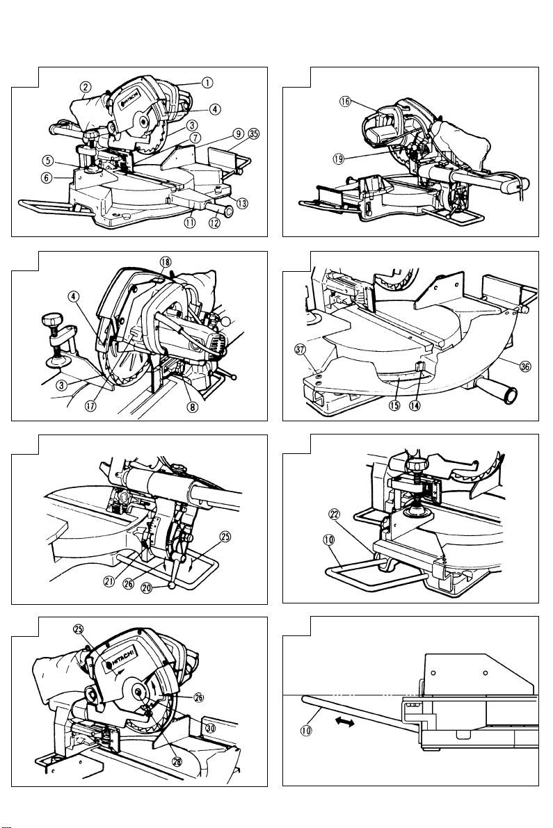
q Handle Griff Poignée
w Dust Bag Staubbeutel
e Safety Cover Sicherheitsabdeckung Capot de sécurité
r Sub Cover Unterabdeckung Capot secondaire
t Vise Assembly Schraubstocksatz Ensemble d’étau
10 mm Knob Bolt 10-mm-Knopfschraube Boulon de 10 mm
y
(for vise Fix) (für Schraubstockbefestigung) (pour la fixation de l’étau)
u Guard Schutz Protection
8 mm Knob Bolt 8-mm-Knopfschraube Boulon de 8 mm
i
(for Guard Fix) (für Schutzbefestigung)
o Fence Gitter Guide
!0 Holder (Optional Accessory) Halter (Sonderzubehör) Support (accessoire en option)
!1 Turntable Drehbühne Plaque tournante
!2 Side Handle Seitengriff Poignée latérale
!3 Base Grundplatte Socle
!4 Indicator Anzeiger Indicateur
!5 Miter Scale Gehrungsskala Graduation à onglet
!6 Trigger Switch Auslöserschalter Interrupteur à détente
!7 Spindle Lock Spindelhebel Verrou en fuseau
!8 Lock Lever Sperrhebel Levier de verrouillage
!9 Locking Pin Verriegelungsstift Goupille de verrouillage
@0 Clamp Lever Klemmhebel Levier de serrage
@1 Indicator Anzeige Indicateur
6 mm Knob Bolt 6-mm-Knopfschraube 6mm Vis moletée de fixation
@2
(for Holder Fix) (zur Befestigung des Halters) de support
@3 Base Holder Grundplattenhalter Porte-socle
@4 6 mm Bolt 6-mm-Schraube Boulon 6 mm
@5 Loosen Lockern Desserrer
@6 Tighten Anziehen Serrer
@7 Saw Blade Sägeblatt Lame de la scìe
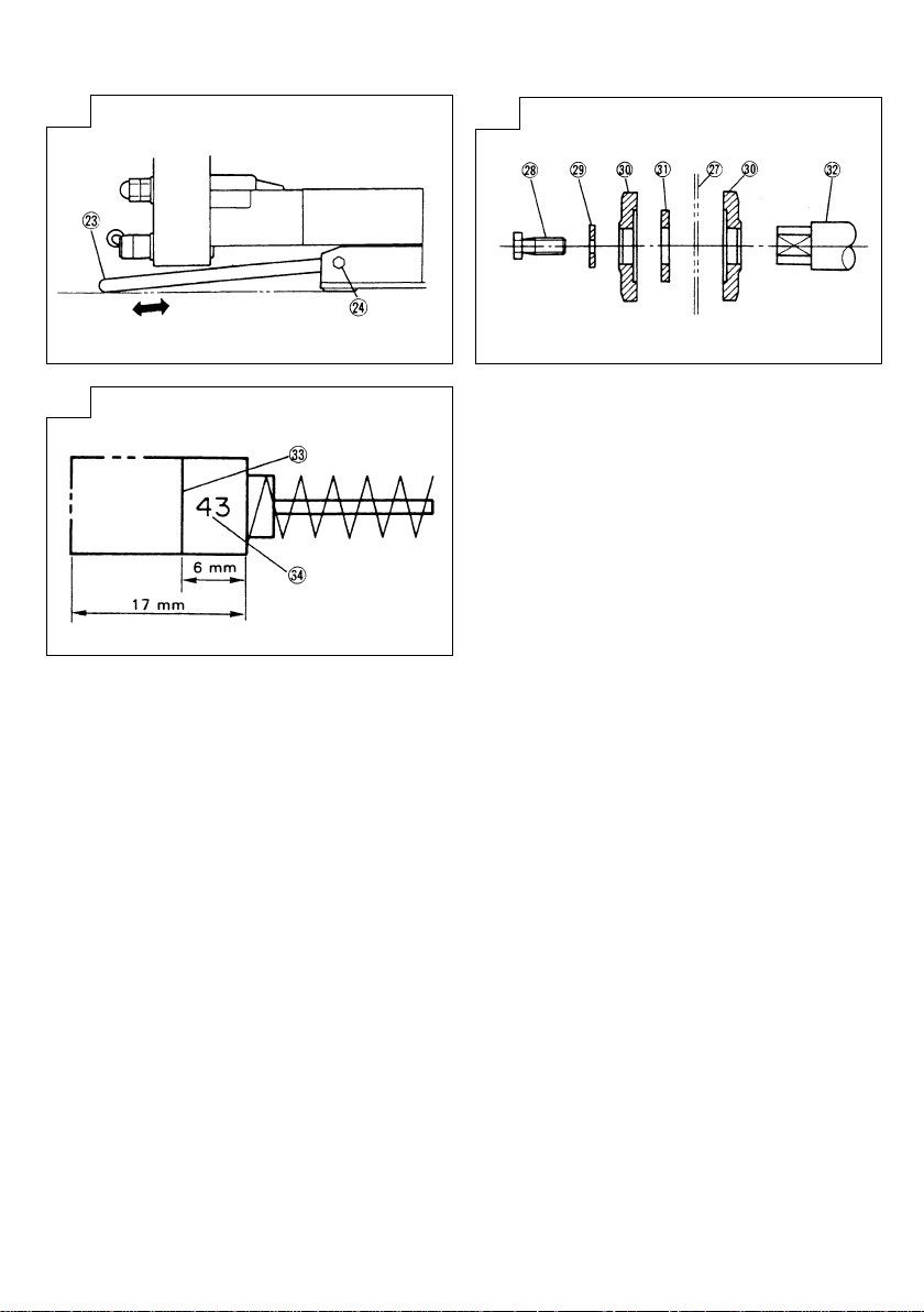
@8 Bolt Schraube Boulon
@9 Washer Unterlegscheibe Rondelle
#0 Washer (C) Unterlegscheibe (C) Rondelle (C)
#1 Collar (A) Kragen (A) Couronne (A)
#2 Spindle Spindel Arbre
#3 Wear limit line Verschleißgrenze Repère de limite d’usure
#4 No. of carbon brush Nr. der Kohlebürste N° du balai carbone
#5 Stopper (Optional Accessory) Anschlag (Sonderzubehör) Butée (accessoire en option)
#6 Sub Table Hilfstisch Plaque secondaire
#7 8 mm Flat Screw 8-mm-Flachkopfschraube Vis à tête de plate de 8 mm
Bacquet de réception des copeaux
(pour la fixation de la protection)
3
Page 5

Italiano Nederlands Español
q Manico Greep Empuñaradura
w Raccoglipolvere Stofzak Bolsa para el polvo
e Coperchio di sicurezza Veiligheidskap Cubierta de seguridad
r Sottocoperchio Hulpkap Cubierta secundaria
t Gruppo morsa Bankschroef
Bullone a manopola da 10 mm 10 mm bout Perno de perilla
y
(per il fissaggio della morsa)
u Schermo protettivo Bescherming Protector
Bullone a manopola da 8 mm 8 mm bout Perno de perilla de 8 mm
i
(per il fissaggio dello schermo protettivo)
o Guida di appoggio Geleider Protrección
!0 Supporto (accessorio opzionale) Houder (optioneel toebehoren) Soporte (Accesorio opcional)
!1 Piatto girevole Draaitafel Plataforma
!2 Manico laterale Zijgreep Asa lateral
!3 Base Basis Base
!4 Indicatore Indicator Indicador
!5 Scala ad angolo Verstekzaagschaal Escala de ingletes
!6 Interruttore a grilletto Startschakelaar Gatillo
!7 Fermo dell’alberino Spilvergrendeling Seguro del eje
!8 Leva di blocco Vergrendelhendel Palanca inmovilizadora
!9 Perno di blocco Vergrendelpen Pasador de bloqueo
@0 Leva morsetto Klemhendel Palanca de fijación
@1 Indicatore Indicator Indicador
6 mm Bullone a manopola 6 mm bout 6 mm Perno de perilla
@2
(per fissare il supporto) (voor bevestigen houder) (de fijación del soporte)
@3 Portabase Basishouder Soporte de la base
@4 Bullone da 6 mm 6 mm bout Perno de 6 mm
@5 Allentare Losdraaien Soltar
@6 Serrare Vastdraaien Apretar
@7 Lama della sega Zaagblad Cuchilla de sierra
@8 Bullone Schroef Perno
@9 Rondella Sluitring Arandela
#0 Rondella (C) Sluitring (C) Arandela (C)
#1 Collare (A) Kraag (A) Collar (A)
#2 Alberino Spil Eje
#3 Riga di limite usura Slijtagegrens Línea de límite de desgaste
#4 N. della spazzola di carbone Nr. van de koolborstel Núm. de escobilla de carbón
#5 Fermo (accessorio opzionale) Aanslag (optioneel toebehoren) Retén (Accesorio opcional)
#6 Tavola secondaria Sub-tafel Mesa secundaria
#7 Vite piatta da 8 mm 8 mm schroef met platte kop
(voor vergrendelen van de klembeugel)
(voor vergrendelen van) (para fijación del protector)
Conjunto del tornillo de carpintero
(para fijación del tornillo)
Tornillo de cabeza plana de 8 mm
4
Page 6

English
GENERAL OPERATIONAL PRECAUTIONS
WARNING!
When using power tools basic safety precautions should
always be followed to reduce the risk of fire, electric shock
and personal injury, including the following.
Read all these instructions before attempting to operate
this product and save these instructions.
1. Keep work area clean. Cluttered areas and benches
invite injuries.
2. Consider work area environment. Do not expose
power tools to rain. Do not use power tools in
damp or wet locations. Keep work area well lit.
Do not use tools in the presence of flammable
liquids or gases.
Power tools produce sparks during operation. They
also spark when switching ON/OFF. Never use
power tools in dangerous sites containing lacquer,
paint, benzine, thinner, gasoline, gases, adhesive
agents, and other materials which are combustible
or explosive.
3. Guard against electric shock. Avoid body contact
with earthed or grounded surfaces. For example;
pipes, radiators, refrigerator enclosures.
4. Keep other persons away. Do not let persons,
especially children, not involved in the work touch
the tool or the extension cord and keep them
away from the work area.
5. Store idle tools. When not in use, tools should
be stored in a dry locked-up place, out of reach
of children.
6. Do not force the tool. It will do the job better and
safer at the rate for which it was intended.
7. Use the right tool. Do not force small tools to do
the job of a heavy duty tool. Do not use tools
for purposes not intended; for example do not use
circular saws to cut tree limbs or logs.
8. Dress properly. Do not wear loose clothing or
jewelry. They can be caught in moving parts. Nonskid footwear is recommended when working
outdoors. Wear protective hair covering to contain
long hair.
9. Use protective equipment. Use safety glasses. Use
face or dust mask if cutting operations create dust.
10. Connect dust extraction equipment.
If device are provided for the connection of dust
extraction and collecting equipment, ensure these
are connected and properly used.
11. Do not abuse the cord. Never yank the cord to
disconnect it from the receptacle. Keep the cord
away from heat, oil and sharp edges.
12. Secure work. Where possible use clamps or a vise
to hold the work. It is safer than using your hand.
13. Do not overreach. Keep proper footing and balance
at all times.
14. Maintain tools with care. Keep cutting tools sharp
and clean for better and safer performance. Follow
instructions for lubricating and changing
accessories. Inspect tool cords periodically and if
damaged have them repaired by an authorized
service facility. Inspect extension cords periodically
and replace if damaged. Keep handles dry, clean
and free from oil and grease.
15. Disconnect tools. When not in use, before servicing
and when changing accessories such as blades,
bits and cutters, disconnect tools from the power
supply.
16. Remove adjusting keys and wrenches. Form the
habit of checking to see that keys and adjusting
wrenches are removed from the tool before turning
it on.
17. Avoid unintentional starting. Do not carry pluggedin tool with finger on switch. Ensure switch is in
“off” position when plugging in.
5
18. Use outdoor extension leads. When the tool is
used outdoors, use only extension cords intended
for outdoor use and so marked.
19. Stay alert. Watch what you are doing. Use common
sense. Do not operate the tool when you are tired.
20. Check damaged parts. Before further use of tool,
it should be carefully checked to determine that
it will operate properly and perform its intended
function. Check for alignment of moving parts,
binding of moving parts, breakage of parts,
mounting and any other conditions that may affect
its operation. A guard or other part that is damaged
should be properly repaired or replaced by an
authorized service center unless otherwise
indicated in this handling instructions. Have
defective switches replaced by an authorized
service center. Do not use the tool if the switch
does not turn it on and off.
21. Do not use power tools for applications other than
those specified in the handling instructions.
22. Warning
The use of any accessory or attachment other
than one recommended in this handling
instructions or the HITACHI catalog may present
a risk of personal injury.
23. Repairing must be done only by authorized service
facility. Manufacturer is not responsible for any
damages and injuries due to the repair by the
unauthorized persons as well as the mishandling
of the tool.
24. Have your tool repaired by a qualified person.
This power tool complies with the relevant safety
rules. Repairs should only be carried out by
qualified persons using original spare parts,
otherwise this may result in considerable danger
to the user.
25. To ensure the designed operational integrity of
power tools, do not remove installed covers or
screws.
26. Do not touch movable parts or accessories unless
the power source has been disconnected.
27. Use your tool at lower input than specified on the
nameplate; otherwise, the finish may be spoiled
and working efficiency reduced due to motor
overload.
28. Do not wipe plastic parts with solvent. Solvents
such as gasoline, thinner, benzine, carbon
tetrachloride, alcohol, may damage and crack
plastic parts. Do not wipe them with such solvent.
Clean plastic parts with a soft cloth lightly
dampened with soapy water.
29. Use only original HITACHI replacement parts.
30. This tool should only be disassembled for
replacement of carbon brushes.
31. The exploded assembly drawing on this handling
instructions should be used only for authorized
service facility.
PRECAUTION FOR SLIDE COMPOUND SAW
1. Never use the slide compound saw with its safety
cover locked in the open position.
2. Ensure that the safety cover moves smoothly.
3. Do not use the saw without guards in position.
4. Always keep the saw blade sharp.
5. Do not use saw blades which are damaged or
deformed.
6. Use only saw blades recommended by HITACHI.
7. Select saw blades in relation to the material to
be cut.
8. Never operate the slide compound saw with the
saw blade turned upward or to the side.
9. Ensure that the workpiece is free of foreign matter
such as nails.
Page 7

English
10. Replace table insert when worn.
11. Do not use the saw to cut other than aluminium,
wood or similar materials.
12. Connect slide compound saw to a dust collecting
device when sawing.
13. Take care when slotting.
14. When transporting or carrying the tool, do not
grasp the holder. Grasp the handle instead of the
holder.
15. Start cutting only after motor revolution reaches
maximum speed.
16. Promptly cut OFF the switch when abnormality
observed.
17. Shut off power and wait for saw balde to stop
before servicing or adjusting tool.
18. During slide cutting operation, the saw must be
pushed and slided away from the operater.
19. During a miter or bevel cut the blade should not
be lifted until it has stopped rotation completely.
SPECIFICATIONS
Max. Cutting
Capacity
Height x Width
Saw Blade Diameter 216mm
Miter Cutting Angle Right and left 0° – 57°
Bevel Cutting Angle Left 0° – 47°
Input 920W*
No-Load Speed 5000/min
Machine Dimensions (Width × Depth × Height) 660mm × 1150mm × 465mm
Weight (Net) 25 kg
* Be sure to check the nameplate on product as it is subject to change by areas.
STANDARD ACCESSORIES
(1) 216 mm TCT Saw blade (mounted on tool) ..... 1
(2) Dust bag .................................................................... 1
(3) 10 mm Box wrench ................................................ 1
(4) Vise Assembly .......................................................... 1
(For England, France, Italy, Singapore)
(5) Sub Table (with four M8 flat screws) ................. 1
(For England, France)
Standard accessories are subject to change without
notice.
Standard accessories are subject to change by areas.
OPTIONAL ACCESSORIES (SOLD SEPARATELY)
(1) Guide Assembly
Optional accessories are subject to change without
notice.
0° 65mm × 305mm
Miter 45° 65mm × 220mm
Bevel 45° 45mm × 305mm
Miter + Bevel 45° 45mm × 220mm
2. Power switch
Ensure that the power switch is in the OFF position. If
the plug is conencted to a receptacle while the trigger
switch is in the ON position, the power tool will start
operating immediately, inviting serious accident.
3. Extention cord
When the work area is removed from the power
source, use an extension cord of sufficient thickness
and rated capacity. The extension cord should be kept
as short as practicable.
4. When the tool is shipped, its movable parts are locked
by the locking pin. Move the handle a little and remove
the locking pin by pulling it as illustrated in Fig. 2.
5. Attach the dust bag to the main unit (Fig. 1).
6. Assembly of sub table.
Assembling the sub table using the four 8 mm flat
screws (Fig. 4).
ADJUSTING THE POWER TOOL PRIOR TO USE
APPLICATION
䡬 Cutting various types of wood.
UNPACKING
䡬 Carefully unpack the power tool and all related items
(standard accessories).
䡬 Check carefully to make certain all related items
(standard accessories) are present.
PRIOR TO OPERATION
1. Power source
Ensure that the power source to be utilized conforms
to the power requirements specified on the product
nameplate.
CAUTION
Make all necessary adjustments before inserting the plug
in the power source.
1. Check to see that the safety cover operates smoothly.
(1) When push down the handle while holding down the
lever, check that the safety cover revolves smoothly
(Fig. 3).
(2) Next, check that the safety cover returns to the original
position when the handle is raised.
2. Saw blade height adjustment (Fig. 2).
The main unit has as standard equipment a saw blade
with an outer diameter of 216 mm and adjustable
cutting depth. Follow the steps outlined below of
adjustment when using a saw-blade with an outer
diameter which is greater than 216 mm.
6
Page 8

English
(1) Use the 8 mm depth adjustment bolt on the gear case
for adjustments. Turning the 8 mm depth adjustment
bolt to the left increases the cutting depth (Fig. 2).
CAUTION
Ensure the height is adjusted securely so that the saw
blade does not contact the turntable.
PRACTICAL APPLICATIONS
CAUTION
䡬 It is dangerous to remove or install the wrokpiece
while the saw blade is turning.
䡬 When sawing, clean off the shavings from the
turntable.
䡬 If the shavings accumulate too much, the saw blad
from the cutting material will be exposed. Never
subject your hand or anything else to go near the
exposed blade.
1. Tightly secure the material by vise assembly to be
cut so that it does not move during cutting.
2. Switch operation.
Pulling the trigger turns the switch on. Releasing the
trigger turns the switch off.
3. Base holder adjustment (Fig. 9).
Loosen the 6 mm bolt with the supplied 10 mm box
wrench. Adjust the base holder until its bottom surface
contacts the bench or the floor surface.
4. Cutting a groove on the guard.
Holder (A) has a guard (see Fig. 1) into which a groove
must be cut. Loosen the 8 mm knob bolt to retract the
guard slightly.
After placing a suitable wooden piece to sit on the
fence and the table surfaces, fix it with the vise. After
the switch has been turned on and the saw blade has
reached maximum speed, slowly lower the handle to
cut a groove on the guard.
CAUTION
Do not cut the groove too quickly; otherwise the guard
might become damaged.
5. Adjusting the guard (Fig. 3).
(1) In the case of cutting at a right angle or bevel cutting:
Loosen the 8 mm knob bolt, bring the guard lightly in
contact with the materials to be cut and secure. Align
the ink line with the saw blade groove on the guard
and begin operations.
(2) In the case of miter cutting or miter cutting plus bevel
cutting.
Loosen the 8 mm knob bolt, move the guard to the
back, making sure that it is not sticking out from the
fence surface.
6. Cutting operation
(1) After turning on the switch and checking that the saw
blade is rotating at maximum speed, slowly push
down the handle while holding down the lever and
bring the equipment in the vicinity of the material to
be cut.
(2) When the saw blade contacts the workpiece, push the
handle down gradually to produce cutting.
(3) When the cutting (or desired cutting-in) has been
completed, raise the handle up to the retract position.
(4) Turn the tool OFF after each cutting operation is
completed, and allow the saw blade to come to a
complete stop before preparing for the next operation.
7
CAUTION
䡬 Increased pressure on the handle does not
necessarily mean faster cutting of the workpiece.
On the contrary, too much force may result in
overload of the motor and/or decreased cutting
efficiency.
䡬 Ensure the switch is turned OFF and the plug is
removed from the power outlet when work has
been completed.
7. Miter cutting procedure (Fig. 4).
(1) Loosen the side handle and adjust the turntable until
the indicator aligns with the desired setting on the
miter scale.
(2) Re-tighten the side handle to secure the turntable in
the desired position.
(3) The miter scale indicates both the cutting angle on
the angle scale and the gradient on the grade scale.
(4) The gradient angle fellows the ratio of the vertical
height versus the bottom length of the workpiece.
(5) Therefore, to cut a workpiece at a grade of 2/10, set
the indicator to position 2/10.
NOTE
䡬 Positive stops are at right and left angles 0˚, 15˚,
22.5˚, 30˚, and 45˚ to the center.
䡬 Check that the miter scale and the tip of the
indicator are properly aligned.
䡬 Operation of the saw with the miter scale and
indicator out of alignment, or with the side handle
not properly tightened, will result in poor cutting
precision.
8. Bevel cutting procedure (Fig. 5).
(1) Loosen the clamp lever and bevel the saw blade to
the left.
(2) Adjust the bevel angle to the desired setting while
watching the scale and indicator, then secure the
clamp lever.
(3) Perform cutting as deseribed in 5.
CAUTION
䡬 During an bevel cut, it will create a condition where
the piece cut off will come to rest on the saw blade.
䡬 If the handle is raised while the saw blade is still
rotating, the cut-off piece may become jammed
against the saw blade causing fragments to scatter
about dangerously.
9. Compound cutting
Compound cutting can be performed by following the
instructions in 7 and 8 above. At a bevel of 45° and a
miter angle of 45°.
WARNING
䡬 Always secure the workpiece with the right hand
side for compound cutting.
䡬 Never rotate the turntable to the right for
compound cutting, because the saw blade might
then contact the clamp or vise that secures the
workpiece, and cause personal injury or damage.
10. Cutting long materials
When cutting long materials, use an auxiliary platform
which is the same height as the holder and base of
the special auxiliary equipment. Insert the holder in
the hole on the right and left side of the base and
secure (Fig. 6).
Adjust the holder upon inserting so that it is the same
height as the base (Fig. 8).
After adjusting the height of the holder use the
securing knob bolt to secure the holder.
Page 9

English
CAUTION
䡬 When transporting or carrying the tool, do not
grasp the holder.
䡬 There is the danger of the holder slipping out of
the base. Grasp the handle instead of the holder.
MOUNTING AND DISMOUNTING SAW BLADE
WARNING
To prevent an accident or personal injury, always turn off
the trigger switch and disconnect the power plug from
the receptacle before removing or installing a blade.
1. Mounting the saw blade (Fig. 7 and Fig. 10).
(1) Press in spindle lock and loosen bolt with 10 mm box
wrench. Since the bolt is left-hand threaded, loosen
by turning it to the right.
NOTE
If the spindle lock cannot be easily pressed in to lock
the saw blade spindle, turn the bolt with 10 mm box
wrench while applying pressure on the spindle lock.
The saw blade spindle is locked when the spindle lock
is pressed inward.
(2) Remove the bolt and washer (C) and collar (A).
(3) Before mounting the saw blade, carefully clean and
re-install the collar (A). The collar (A) has an outside
diameter of 30 mm as shown in Fig. 10.
(4) Lift the safety cover and sub cover and mount the saw
balde.
WARNING
When mounting the saw blade, confirm that the
rotation indicator mark on the saw blade and the
rotation direction of the saw are properly matched.
(5) Thoroughly clean washer (C) and the bolt, and install
them onto the saw blade spindle.
(6) Press in the spindle lock and tighten the bolt by turning
it to the left by 10 mm box wrench as in Fig. 3 and Fig.
7.
CAUTION
䡬 Confirm that the spindle lock has returned to the
retract position after installing or removing the saw
blade.
䡬 Tighten the bolt so it does not come loose during
operation.
䡬 Confirm that the bolt has been properly tightened
before the power tool is started.
2. Dismounting the saw blade
Dismount the saw blade by reversing the mounting
procedures described in paragraph 1 above.
The saw blade can easily be removed after lifting the
safety covers.
CAUTION
䡬 Never attempt to install saw blades larger than
216 mm in diameter. Always install saw blades that
are 216 mm in diameter or less.
2. Inspecting the mounting screws
Regularly inspect all mounting screws and ensure that
they are properly tightened. Should any of the screws
be loose, re-tighten them immediately. Failure to do
so could result in serious hazard.
3. Inspecting the carbon brushes (Fig. 11).
The motor employs carbon brushes which are
consumable parts. Since an excessively worn carbon
brush could result in motor trouble, replace a carbon
brush with a new one when it becomes worn to or
near the “wear limit”. In addition, always keep carbon
brushes clean and ensure that they slide freely within
the brush holders.
4. Replacing a carbon brushes
Disassemble the brush cap with a minus-head
screwdriver. The carbon brushes can then be easily
removed.
5. Maintenance of the motor
The motor unit winding is the very “heart” of the
power tool. Exercise due care to ensure the winding
does not become damaged and/or wet with oil or
water.
6. Lubrication
Lubricate the following sliding surfaces once a month
to keep the power tool in good operating condition
for a long time.
Use of machine oil is recommended.
Oil supply points:
* Rotary portion of hinge
* Rotary portion of vise assembly
* Sliding portion of slide pipe (A) and slide pipe (B)
7. Cleaning
Periodically remove chips and other waste material
from the surface of the power tool with a damp, soapy
cloth. To avoid a malfunction of the motor, protect it
from contact with oil or water.
NOTE
Due to HITACHI’s continuing program of research and
development the specifications herein are subject to
change without prior notice.
MAINTENANCE AND INSPECTION
WARNING
To avoid an accident or personal injury, always confirm
the trigger switch is turned OFF and that the power plug
has been disconnected from the receptacle before
performing any maintenance or inspection of this tool.
1. Inspecting the saw blade
Since use of a dull saw blade will degrade efficiency
and cause possible motor malfunction, sharpen or
replace the saw blade as soon as abrasion is noted.
8
Page 10

Deutsch
VORSICHTSHINWEISE FÜR ALLGEMEINE
BEDIENUNG
WARNUNG!
Bei Verwendung von Elektrowerkzeugen sollten die
grundlegenden Sicherheitsmaßnahmen immer befolgt
werden, um das Risiko von Feuer, elektrischem Schlag
und Körperverletzung zu verringern. Dies schließt die
folgenden Punkte ein.
Lesen Sie alle Anweisungen durch, bevor Sie versuchen,
das Erzeugnis zu bedienen, und heben Sie diese
Anweisungen auf.
1. Der Arbeitsplatz sollte sauber gehalten werden.
Unaufgeräumte Arbeitsplätze und Werkbänke
erhöhen die Unfallgefahr.
2. Die Umgebung des Arbeitsplatzes berücksichtigen.
Elektrowerkzeuge sollten nicht Regen ausgesetzt
werden und auch nicht an feuchten oder nassen
Stellen eingesetzt werden. Der Arbeitsplatz sollte
gut beleuchtet sein.
Das Werkzeug nicht bei Anwesenheit von leicht
entzündlichen Flüssigkeiten oder Gasen
verwenden.
Elektrowerkzeuge erzeugen beim Betrieb und beim
Ein- und Ausschalten Funken. Elektrowerkzeuge
niemals an Orten verwenden, an denen sich Lack,
Farbe, Benzin, Verdünnungsmittel, Gase,
Klebemittel und sonstige brennbare oder explosive
Materialien befinden.
3. Schutzmaßnahmen gegen elektrische Schläge
treffen. Körperkontakt mit geerdeten Flächen wie
Rohre, Heizungen und Kühlschränke vermeiden.
4. Andere Personen vom Werkzeug fernhalten. Keine
anderen Personen, besonders Kinder, die nicht
mit der Arbeit in Zusammenhang stehen, das
Werkzeug oder das Verlängerungskabel berühren
lassen und andere Personen nicht in den
Arbeitsbereich lassen.
5. Nicht verwendete Werkzeuge sicher lagern. Nicht
verwendete Werkzeuge an einem trockenen,
abgeschlossenen Platz außerhalb der Reichweite
von Kindern lagern.
6. Werkzeuge nicht mit Gewalt anwenden. Das
Werkzeug arbeitet bei der vorgesehenen
Geschwindigkeit besser und sicherer.
7. Immer das richtige Werkzeug verwenden. Nicht
ein kleines Werkzeug für Arbeit verwenden, die
ein Hochleistungswerkzeug erfordert. Werkzeuge
nicht für Arbeiten verwenden, für die sie nicht
vorgesehen sind: z.B. nicht eine Kreissäge zum
Sägen von Ästen oder Baumstämmen verwenden.
8. Die richtige Kleidung tragen. Keine lose Kleidung
oder Schmuck tragen, da diese sich an sich
bewegenden Teilen verfangen können. Für Arbeit
im Freien werden rutschfeste Schuhe empfohlen.
Bei langem Haar eine Haarabdeckung verwenden.
9. Schutzausrüstung verwenden. Eine
Sicherheitsbrille tragen. Wenn Schneidarbeit Staub
erzeugt, eine Gesichts- oder Staubmaske tragen.
10. Staubabsaugausrüstung anschließen.
Wenn ein Anschluß für Staubabsaug- und
Sammelausrüstung vorgesehen ist, diese
Ausrüstung anschließen und richtig verwenden.
11. Niemals das Kabel mißbrauchen. Beim
Herausziehen aus der Steckdose nicht am Kabel
ziehen. Das Kabel nicht Hitze, Öl oder scharfen
Kanten aussetzen.
12. Das Werkstück sichern. Wenn möglich, Zwingen
oder einen Schraubstock zum Halten des
Werkstücks verwenden. Dies ist sicherer als Halten
mit der Hand.
13. Nicht zu weit vorbeugen. Immer einen festen Stand
und gute Balance bewahren.
9
14. Werkzeuge sorgfältig warten. Schneidwerkzeuge
für besseren und sichereren Betrieb immer scharf
und sauber halten. Die Anweisungen für Schmieren
und Auswechseln von Zubehör befolgen. Die
Werkzeugkabel regelmäßig inspizieren und sie bei
Beschädigung durch autorisierte
Wartungseinrichtungen reparieren lassen.
Verlängerungskabel periodisch inspizieren und sie
bei Beschädigung austauschen. Handgriffe sauber,
trocken und frei von Öl oder Fett halten.
15. Werkzeuge vom Netz trennen, wenn sie nicht
verwendet werden und vor Wartung bzw. vor dem
Auswechseln von Zubehörteilen wie Sägeblätter,
Bohrer usw.
16. Einstellschlüssel und Schraubenschlüssel
entfernen. Vor dem Einschalten des Werkzeugs
immer überprüfen, daß Einstellschlüssel und
Schraubenschlüssel entfernt worden sind.
17. Ungewollten Start vermeiden. Angeschlossenes
Werkzeug nicht mit dem Finger am Schalter tragen.
Vor dem Anschluß sicherstellen, daß das Werkzeug
ausgeschaltet ist.
18. Bei Verwendung im Freien ein angemessenes
Verlängerungskabel verwenden. Bei Verwendung
im Freien nur ein für Verwendung im Freien
vorgesehenes und entsprechend markiertes
Verlängerungskabel verwenden.
19. Wachsam bleiben. Aufpassen und gesunden
Menschenverstand verwenden. Das Werkzeug nicht
in ermüdetem Zustand verwenden.
20. Beschädigte Teile überprüfen. Vor
Weiterverwendung des Werkzeugs sorgfältig
überprüfen, daß es richtig funktioniert und seine
vorgesehene Funktion erfüllt. Auf Ausrichtung und
Klemmen von sich bewegenden Teilen, Bruch von
Teilen, Anbringung und sonstige Zustände, die
den Betrieb beeinträchtigen können, überprüfen.
Beschädigte Teile oder Schutzvorrichtungen sollten
durch ein autorisiertes Wartungszentrum
ausgewechselt werden, wenn nicht in dieser
Bedienungsanleitung anders angegeben. Defekte
Schalter in einem autorisierten Wartungszentrum
auswechseln lassen. Das Werkzeug nicht
verwenden, wenn es nicht mit dem Schalter einund ausgeschaltet werden kann.
21. Elektrowerkzeuge nur für die in der
Bedienungsanleitung angeführten Anwendungen
verwenden.
22. Warnung
Verwendung von nicht in dieser
Bedienungsanleitung oder im Hitachi-Katalog
angeführtem Zubehör oder Sonderzubehör kann
zum Risiko von Körperverletzungen führen.
23. Reparaturen dürfen nur durch autorisierte
Wartungseinrichtungen durchgeführt werden. Der
Hersteller ist nicht verantwortlich für
Beschädigungen oder Verletzungen, die durch
Reparatur durch nicht autorisierte Personen oder
durch Mißbrauch des Werkzeugs verursacht
werden.
24. Das Werkzeug nur durch qualifiziertes Personal
reparieren lassen. Dieses Elektrowerkzeug
entspricht den zutreffenden Sicherheitsvorschriften.
Reparaturen sollten nur durch qualifiziertes
Personal mit Originalersatzteilen durchgeführt
werden, da der Benutzer sonst beträchtlichen
Gefahren ausgesetzt werden kann.
25. Zur Sicherstellung der Betriebsintegrität von
Elektrowerkzeugen niemals installierte
Abdeckungen oder Schrauben entfernen.
26. Bewegliche Teile und Zubehör nur berühren, wenn
das Werkzeug nicht an die Stromversorgung
angeschlossen ist.
27. Das Werkzeug mit einer geringeren
Leistungsaufnahme als auf dem Typenschild
Page 11

Deutsch
angezeigt verwenden, da sonst durch Überlastung
die Qualität der bearbeiteten Oberfläche bzw. der
Wirkungsgrad beeinträchtigt werden kann.
28. Plastikteile nicht mit Lösungsmittel abwischen.
Lö sungsmittel wie Benzin, Verdünner,
Kohlenstofftetrachlorid oder Alkohol können
Plastikmaterial beschädigen oder Risse
verursachen. Nie mit Lösungsmittel abwischen.
Plastikteile mit einem mit Seifenwasser
angefeuchteten weichen Lappen reinigen.
29. Nur Originalersatzteile von Hitachi verwenden.
30. Dieses Werkzeug sollte nur zum Auswechseln der
Kohlebürsten zerlegt werden.
31. Die Explosionszeichnung in dieser
Bedienungsanleitung ist nur für autorisierte
Wartungseinrichtungen gedacht.
VORSICHTSHINWEISE FÜR BENUTZUNG DER
HANDKREISSÄGE
1. Die Handkreissäge niemals mit der
Schutzabdeckung in offener Position verriegelt
verwenden.
2. Sicherstellen, daß sich die Schutzabdeckung glatt
bewegt.
3. Die Säge nicht ohne angebrachten Schutz
verwenden.
4. Das Sägeblatt immer scharf halten.
5. Keine beschädigten oder verformten Sägeblätter
verwenden.
6. Nur von Hitachi empfohlene Sägeblätter
verwenden.
7. Sägeblätter entsprechend dem zu sägenden
Material auswählen.
8. Niemals die Handkreissäge mit dem Sägeblatt
nach oben oder zur Seite hin verwenden.
9. Sicherstellen, daß das Werkstück keine Nägel oder
sonstigen Fremdmaterialien enthält.
10. Den Tischeinschub ersetzen, wenn er abgenutzt
ist.
11. Die Säge nur zum Schneiden von Aluminium, Holz
oder ähnlichen Materialien verwenden.
12. Die Handkreissäge beim Sägen an einen
Staubsammler anschließen.
13. Beim Schlitzen Vorsicht walten lassen.
14. Das Werkzeug beim Tragen oder Transport nicht
an der Bodenplatte, sondern am Handgriff halten.
15. Erst mit dem Sägen beginnen, wenn das Werkzeug
die maximale Drehzahl erreicht hat.
16. Den Schalter sofort ausschalten, wenn eine Störung
bemerkt wird.
17. Vor Wartung oder Einstellung des Werkzeugs
immer die Stromversorgung ausschalten und
warten, bis das Sägeblatt angehalten hat.
18. Beim Sägen muß die Säge von der Bedienung
weg geschoben werden.
19. Bei Gehrungs- oder Schrägschnitten das Sägeblatt
erst anheben, nachdem es vollkommen angehalten
hat.
TECHNISCHE DATEN
Maximale Schneidleistung
Höhe × Breite
Gehrung + Schrägschnitt 45° 45mm × 220mm
Sägeblatt durch messer 216mm
Gehrungsschnittwinkel Rechts und links 0° bis 57°
Schrägschnittwinkel Rechts und links 0° bis 47°
Leistungsaufnahme 920W*
Leerlaufdrehzahl 5000/min
Maschinenabmessungen (Breite × Tiefe × Höhe) 660mm × 1150mm × 465mm
Gewicht (netto) 25 kg
* Überprüfen Sie die Angaben auf dem Typenschild, da sich diese je nach dem Verkaufsgebiet ändern.
0° 65mm × 305mm
Gehrung 45° 65mm × 220mm
Schrägschnitt 45° 45mm × 305mm
STANDARDZUBEHÖR
(1) 216 mm TCT-Sägeblatt
(am Werkzeug angebracht) .................................... 1
(2) Staubbeutel ................................................................ 1
(3) 10 mm Steckschlüssel ............................................. 1
(4) Schraubstocksatz ....................................................... 1
(Für England, Frankreich, Italien und Singapur)
(5) Hilfstisch (mit vier M8-Flachkopfschrauben) ....... 1
(Für England und Frankreich)
Änderungen des Standardzubehörs bleiben jederzeit
vorbehalten.
Das Standardzubehör kann sich je nach dem Bereich
ändern.
SONDERZUBEHÖR (SEPARAT ZU BEZIEHEN)
(1) Führungsbaugruppe ................................................. 1
Änderungen des Sonderzubehörs bleiben jederzeit
vorbehalten.
ANWENDUNG
䡬 Schneiden verschiedener Holzarten.
AUSPACKEN
䡬 Das Elektrowerkzeug und alle Teile (Standardzubehör)
sorgfältig auspacken.
䡬 Sicherstellen, daß alle Teile (Standardzubehör)
vorhanden sind.
10
Page 12

Deutsch
VOR DER VERWENDUNG
1. Stromversorgung
Sicherstellen, daß die zu verwendende
Stromversorgung den Angaben auf dem Typenschild
entspricht.
2. Netzschalter
Sicherstellen, daß der Netzschalter ausgeschaltet ist.
Wenn der Stecker bei eingeschaltetem Schalter an
eine Steckdose angeschlossen wird, fängt das
Elektrowerkzeug sofort an zu laufen, und es kann zu
einem schweren Unfall kommen.
3. Verlängerungskabel
Bei Arbeit entfernt von einer Steckdose ein
Verlängerungskabel ausreichender Dicke und
Nennkapazität verwenden. Das Verlängerungskabel so
kurz wie möglich halten.
4. Beim Versand des Werkzeugs sind die beweglichen
Teile durch einen Verriegelungsstift verriegelt. Den
Handgriff etwas bewegen und den Verriegelungsstift
wie in Abb. 2 gezeigt herausziehen.
5. Den Staubbeutel am Gerät anbringen. (Abb. 1)
6. Hilfstischmontage
Den Hilfstisch mit den vier 8 mm Flachkopfschrauben
anbringen. (Abb.4)
EINSTELLUNG DES ELEKTROWERKZEUGS VOR
DER VERWENDUNG
VORSICHT
Alle Einstellungen vor Anschluß des Steckers an die
Steckdose durchführen.
1. Sicherstellen, daß die Schutzabdeckung glatt
funktioniert.
(1) Überprüfen, daß sich die Schutzabdeckung glatt dreht,
wenn der Handgriff gedrückt wird, während der Hebel
gedrückt gehalten wird. (Abb. 3).
(2) Dann überprüfen, daß die Schutzabdeckung in die
Ausgangsstellung zurückkehrt, wenn der Handgriff
angehoben wird.
2. Einstellen der Sägeblatthöhe (Abb. 2)
Das Werkzeug hat als Standardzubehör ein Sägeblatt
mit einem Durchmesser von 216 mm und Einstellung
der Schneidtiefe. Die nachfolgend angeführten
Schritte zur Einstellung befolgen, wenn ein Sägeblatt
mit einem Durchmesser von weniger als 216 mm
verwendet wird.
(1) Die 8-mm-Tiefeneinstellschraube am
Getriebegehäuse zur Einstellung verwenden. Durch
Drehen der 8-mm-Tiefeneinstellschraube nach links
wird die Schneidtiefe größer. (Abb. 2)
VORSICHT
Sicherstellen, daß die Höhe sicher eingestellt ist, so
daß das Sägeblatt nicht mit dem Drehtisch in
Berührung kommt.
PRAKTISCHE ANWENDUNGEN
VORSICHT
䡬 Es ist gefährlich, das Werkstück anzubringen oder zu
entfernen, während sich das Sägeblatt dreht.
䡬 Beim Sägen die Sägespäne vom Drehtisch entfernen.
䡬 Wenn sich zu viele Sägespäne ansammeln, steht das
Sägeblatt aus dem zu sägenden Material heraus.
11
Niemals die Hände oder Gegenstände in die Nähe des
freiliegenden Sägeblattes bringen.
1. Das zu schneidende Material mit dem
Schraubstocksatz fest einspannen, damit es sich beim
Sägen nicht bewegt.
2. Schalterbedienung
Durch Ziehen am Auslöser wird der Schalter
eingeschaltet. Durch Loslassen des Auslösers wird der
Schalter ausgeschaltet.
3. Grundplatteneinstellung (Abb. 9)
Die 6-mm-Schraube mit dem mitgelieferten 10-mmSteckschlüssel lösen. Die Grundplatte so einstellen,
daß die untere Oberfläche die Werkbank oder den
Boden berührt. Nach der Einstellung die 6-mmSchraube fest anziehen.
4. Schneiden einer Nut am Schutz
Der Halter (A) hat einen Schutz (siehe Abb. 1), in den
eine Nut geschnitten werden muß. Die 8-mmKnopfschraube etwas lösen, um den Schutz etwas
einziehen.
Ein passendes Stück Holz auf die Führung und die
Tischoberfläche legen und mit dem Schraubstock
einspannen.
Wenn das Sägeblatt nach Einschalten des Schalters
die maximale Drehzahl erreicht hat, den Handgriff
langsam absenken, um eine Nut in den Schutz zu
schneiden.
ACHTUNG
Die Nut nicht zu schnell schneiden, da sonst der Schutz
beschädigt werden kann.
5. Einstellen des Schutzes (Abb. 3)
(1) Bei Sägen im rechten Winkel oder beim Schrägschnitt:
Die 8-mm-Knopfschraube lösen, den Schutz leicht in
Kontakt mit dem zu schneidenden Material bringen
und dann festziehen. Die Tintenlinie auf die
Sägeblattnut im Schutz ausrichten und mit dem
Betrieb beginnen.
(2) Bei Gehrungssä gen oder Gehrungssägen plus
Schrägschnitt: Die 8-mm-Knopfschraube lösen, den
Schutz nach hinten bewegen, und sicherstellen, daß
er nicht über die Oberfläche der Führung hervorsteht.
6. Sägebetrieb
(1) Den Schalter einschalten, überprüfen, daß sich das
Sägeblatt mit maximaler Drehzahl dreht, und dann
langsam den Handgriff nach unten drücken, während
der Hebel gehalten wird, und die Säge in die Nähe
des zu sägenden Materials bringen.
(2) Wenn das Sägeblatt in Kontakt mit dem zu
schneidenen Material kommt, den Handgriff
allmählich nach unten drücken, um zu sägen.
(3) Wenn der gewünschte Sägeschnitt (oder Einschnitt)
gemacht worden ist, den Handgriff in die
Einzugposition zurückbringen.
(4) Das Werkzeug nach jedem Schnitt ausschalten und
das Sägeblatt zum Stillstand kommen lassen, bevor
der nächste Betrieb vorbereitet wird.
VORSICHT
䡬 Stärkerer Druck auf den Handgriff bedeutet nicht
unbedingt schnelleres Schneiden des Werkstücks.
Zu viel Kraft kann ganz im Gegenteil Überlastung
des Motors und/oder verringerte Schneidleistung
verursachen.
䡬 Am Ende der Arbeit immer sicherstellen, daß der
Schalter ausgeschaltet und der Stecker aus der
Steckdose gezogen ist.
Page 13

Deutsch
7. Gehrungssägen (Abb. 4)
(1) Den Seitengriff lösen und den Drehtisch so einstellen,
daß die Gehrungsskala den gewünschten
Gehrungswinkel anzeigt.
(2) Den Seitengriff wieder anziehen, um den Drehtisch
in der gewünschten Stellung zu sichern.
(3) Die Gehrungsskala zeigt den Schneidwinkel auf
der Winkelskala und den Gradienten auf der
Gradientenskala an.
(4) Der Gradient entspricht dem Verhältnis der
Werkstückhöhe zur Bodenlänge.
(5) Stellen Sie deshalb zum Schneiden eines Werkstücks
im Verhältnis 2/10 die Anzeige auf 2/10.
Hinweise
䡬 Positive Anschläge sind rechts und links an den
Winkeln 0°, 15°, 22,5°, 30° und 45° zur Mitte
vorhanden.
䡬 Sicherstellen, daß die Gehrungsskala und die
Zeigerspitze richtig auf einander ausgerichtet sind.
䡬 Betrieb der Säge mit schlechter Ausrichtung von
Gehrungsskala und Anzeige oder mit nicht fest
angezogenem Seitengriff verursacht schlechte
Sägegenauigkeit.
8. Schrägschneiden (Abb.5)
(1) Den Klemmhebel lösen und das Sägeblatt nach links
kippen.
(2) Den Schrägschnittwinkel unter Beobachtung der Skala
und der Anzeige auf den gewünschten Wert einstellen
und den Klemmhebel fest anziehen.
(3) Sägen wie in Punkt 5 beschrieben durchführen.
VORSICHT
䡬 Beim Schrägschnitt kommt es dazu, daß das
abgeschnittene Stück auf dem Sägeblatt liegt.
䡬 Wenn der Handgriff angehoben wird, während
sich das Sägeblatt noch dreht, kann das
abgeschnittene Stück gegen das Sägeblatt
gedrückt werden, und Splitter können in
gefährlicher Weise weggeschleudert werden.
9. Verbundschneiden
Verbundschneiden kann durch befolgen der
Anweisungen in den obigen Punkten 7 und 8
durchgeführt werden. Sägen mit einem
Neigungswinkel von 45° und einem Gehrungswinkel
von 45°.
WARNUNG
䡬 Bei Verbundschneiden immer das Werkstück mit
der rechten Hand halten.
䡬 Bei Verbundschneiden niemals den Drehtisch nach
rechts drehen, da sonst das Sägeblatt in Kontakt
mit der Zwinge oder dem Schraubstock kommen
kann, womit das Werkstück festgeklemmt ist, und
dies kann zu Körperverletzungen oder
Sachschäden führen.
10. Sägen von langen Materialien
Beim Sägen von langem Material einen Hilfstisch mit
der gleichen Höhe wie der Halter und die Basis des
Sonderzubehörs verwenden. Den Halter in das Loch
an der linken und rechten Seite der Basis einschieben
und ihn sichern. (Abb. 6)
Den Halter beim Einschieben so einstellen, daß er die
gleiche Höhe wie die Basis hat. (Abb. 8)
Nach Einstellen der Höhe des Halters den Halter mit
der Knopfschraube sichern.
VORSICHT
䡬 Den Halter nicht für Transport oder Tragen des
Werkzeugs verwenden.
䡬 Halten Sie das Werkzeug am Handgriff, da die
Gefahr besteht, daß der Halter aus der Grundplatte
herausrutscht.
ANBRINGEN UND ENTFERNEN DES
SÄGEBLATTESE
WARNUNG
Zur Verhütung von Unfällen und Körperverletzungen
immer erst den Schalter ausschalten und den Stecker aus
der Steckdose ziehen, bevor ein Sägeblatt entfernt oder
angebracht wird.
1. Anbringen des Sägeblattes (Abb. 7 und Abb. 10)
(1) Die Spindelverriegelung eindrücken und die Schraube
mit dem 10-mm-Steckschlüssel lösen. Da die
Schraube ein Linksgewinde hat, muß sie durch
Rechtsdrehung gelöst werden.
HINWEIS
Wenn die Spindelverriegelung zur Verriegelung der
Sägeblattespindel nicht einfach eingedrückt werden
kann, die Schraube mit dem 10-mm-Steckschlüssel
drehen, während die Spindelverriegelung nach innen
gedrückt wird. Wenn die Spindelverriegelung nach
innen gedrückt ist, so ist die Sägeblattespindel
verriegelt.
(2) Die Schraube, die Beilegscheibe (C) und die Hülse (A)
entfernen.
(3) Vor dem Anbringen des Sägeblattes die Hülse (A)
sorgfältig reinigen und sie wieder anbringen. Die
Hülse (A) hat wie in Abb. 10 gezeigt einen
Außendurchmesser von 30 mm.
(4) Die Schutzabdeckung und die Hilfsabdeckung
anheben und das Sägeblatt anbringen.
WARNUNG
Beim Anbringen des Sägeblattes sicherstellen, daß
die Drehrichtungsanzeige auf dem Sägeblatt mit der
Drehrichtung des Werkzeugs übereinstimmt.
(5) Die Beilegscheibe (C) und die Schraube gründlich
reinigen und sie auf der Sägeblattespindel anbringen.
(6) Die Spindelverriegelung eindrücken und die Schraube
wie in Abb. 3 und Abb. 7 gezeigt durch Linksdrehen
mit dem 10-mm-Steckschlüssel anziehen.
VORSICHT
䡬 Nach Installieren oder Entfernen des Sägeblattes
sicherstellen, daß die Spindelverriegelung wieder
zurückgezogen worden ist.
䡬 Die Schraube so fest anziehen, daß sie sich beim
Betrieb nicht lockert.
䡬 Vor dem Einschalten des Werkzeugs sicherstellen,
daß die Schraube richtig angezogen worden ist.
2. Ausbauen des Sägeblattes
Das Sägeblatt in umgekehrter Reihenfolge des im
obigen Punkt 1 beschriebenen Einbaus entfernen.
Nach Anheben der Schutzabdeckungen kann das
Sägeblatt einfach entfernt werden.
VORSICHT
䡬 Niemals versuchen, ein Sägeblatt mit einem
größeren Durchmesser als 216 mm zu installieren.
Immer nur Sägeblätter mit einem Durchmesser
von 216 mm oder weniger installieren.
12
Page 14

Deutsch
WARTUNG UND INSPEKTION
WARNUNG
Zur Verhütung von Unfällen und Körperverletzungen
immer erst den Schalter ausschalten und den Stecker aus
der Steckdose ziehen, bevor Wartung oder Inspektion
dieses Werkzeugs durchgeführt wird.
1. Inspektion des Sägeblattes
Da Verwendung eines stumpfen Sägeblattes die
Schnittleistung verringert und zu Fehlfunktion des
Motors führen kann, das Sägeblatt schärfen oder
auswechseln, wenn Abnutzung festgestellt wird.
2. Inspektion der Befestigungsschrauben
Alle Befestigungsschrauben regelmäßig inspizieren
und sicherstellen, daß sie richtig angezogen sind.
Sollten sich Schrauben gelockert haben, sind diese
sofort wieder fest anzuziehen, da es sonst zu schweren
Unfällen kommen kann.
3. Inspektion der Kohlebürsten (Abb. 11)
Der Motor verwendet Kohlebürsten, die
Verschleißteile sind. Da übermäßig abgenutzte
Kohlebürsten Motorstörungen verursachen können, sollten
Kohlebürsten ausgewechselt werden, wenn sie bis zur
Verschleißgrenze oder nahe daran abgenutzt worden
sind. Die Kohlebürsten immer sauber halten und
sicherstellen, daß sie frei in den Bürstenhaltern gleiten
können.
4. Auswechseln von Kohlebürsten
Die Bürstenkappe mit einem flachen Schraubenzieher
entfernen. Dann kann die Kohlebürste einfach entfernt
werden.
5. Wartung des Motors
Die Motorwicklung ist das “Herz” des Werkzeugs.
Immer darauf achten, daß die Wicklung nicht
beschädigt wird und daß sie nicht durch Wasser oder
Öl angefeuchtet wird.
6. Schmierung
Die folgenden gleitenden Oberflächen einmal im
Monat schmieren, um das Elektrowerkzeug lange Zeit
in gutem Betriebszustand zu halten.
Die Verwendung von Maschinenöl wird empfohlen.
Zu schmierende Punkte:
* Drehteil des Scharniers
* Drehteil des Schraubstocks
* Gleitende Teile von Gleitrohr (A) und Gleitrohr (B)
7. Reinigung
Sägespäne und sonstige Abfälle regelmäßig mit
einem mit Seifenwasser angefeuchteten Lappen
entfernen. Den Motor zur Verhütung von Störungen
vor Kontakt mit Öl oder Wasser schützen.
HINWEIS
Aufgrund des ständigen Forschungs- und
Entwicklungsprogramms von HITACHI bleiben
Änderungen der hierin gemachten technischen Angaben
vorbehalten.
13
Page 15

Français
PRÉCAUTIONS GÉNÉRALES DE TRAVAIL
AVERTISSEMENT!
Pour éviter tout risque de feu, de choc électrique et de
blessure pendant l’utilisation d’un outil électrique,
toujours observer des consignes de sécurité de base, et
notamment les suivantes.
Lire tout ce mode d’emploi avant de faire fonctionner
l’outil, et le conserver.
1. Maintenir l’aire de travail propre. Des ateliers ou
des établis en désordre risquent de provoquer des
accidents.
2. Tenir compte de l’environnement de l’aire de
travail.
Ne pas exposer les outils électriques à la pluie.
Ne pas les utiliser dans des endroits humides.
Travailler dans un endroit bien éclairé.
Ne pas utiliser cet outil à proximité de liquides
ou de gaz inflammables.
Les outils électriques produisent des étincelles
lors de leur utilisation. Des étincelles se produisent
également quand on les met sous/hors tension.
Ne jamais utiliser d’outil électrique dans des
endroits dangereux contenant de la laque, de la
peinture, de la benzine, du solvant, de l’essence,
des gaz, des produits adhésifs et d’autres produits
combustibles ou explosifs.
3. Protection contre une décharge électrique. Eviter
tout contact corporel avec des surfaces de mise
à la terre telles que tuyaux, radiateurs, cuisinières,
réfrigérateurs.
4. Ne laisser personne pénétrer dans l’aire de travail.
5. Ranger les outils non utilisés. Quand on ne les
utilise pas, il est recommandé de ranger les outils
dans un endroit sec, verrouillé ou hors de portée
des enfants.
6. Ne pas forcer l’outil. Il fonctionnera mieux et plus
sûrement à la vitesse pour laquelle il a été conçu.
7. Utiliser l’outil qui convient. Ne pas utiliser de force
des outils de petite dimension pour effectuer le
travail d’un outil à grand rendement. Ne pas utiliser
les outils pour un usage pour lequel ils ne sont
pas conçus, par exemple ne pas utiliser une scie
circulaire pour couper des branches d’arbre ou
des billots de bois.
8. Porter des vêtements appropriés. Ne pas porter
de vêtements lâches ni de bijoux. Ils pourraient
se coincer dans les pièces en rotation. Il est
recommandé de porter des chaussures antidérapantes quand on travaille à l’extérieur. Porter
un couvre-chef qui recouvre les cheveux longs.
9. Utiliser un équipement de protection. Porter des
lunettes de protection. Porter un masque ou un
masque anti-poussière si le travail doit produire
de la poussière.
10. S’il existe des accessoires à raccorder pour
l’extraction et le ramassage de la poussière, bien
les raccorder et les utiliser correctement.
11. Ne pas maltraiter les cordons. Ne jamais tirer
violemment sur le cordon pour le débrancher de
la prise. Eloigner le cordon de la chaleur, des
graisses et des surfaces tranchantes.
12. Fixer la pièce. Chaque fois que cela est possible,
utiliser des dispositifs de serrage ou un étau pour
tenir la pièce. Cela sera plus sûr que de tenir la
pièce à la main.
13. Ne pas trop se pencher. Garder une bonne assise
et un bon équilibre à tout moment.
14. Entretenir les outils avec soin. Maintenir les outils
de coupe aiguisés et propres pour optimiser le
travail et la sécurité. Suivre les instructions de
graissage et de remplacement des accessoires.
Vérifier périodiquement les cordons d’outil et les
faire réparer par un centre de réparation agréé
s’ils sont endommagés. Vérifier périodiquement
les cordons de rallonge et les faire remplacer s’ils
sont endommagés. Maintenir les poignées sèches
et propres, et enlever toute graisse et toute huile
dessus.
15. Débrancher les outils. Lorsqu’on ne s’en sert pas,
avant un entretien et lors du remplacement des
accessoires, comme les lames, forets et couteaux,
débrancher les outils de la source d’alimentation.
16. Retirer les clavettes de réglage et les clés. Prendre
l’habitude de vérifier si les clés et les clavettes
de réglage sont bien retirées de l’outil avant de
le mettre en marche.
17. Eviter toute mise en marche inopinée. Ne pas
transporter l’outil avec le doigt sur l’interrupteur
lorsqu’il est branché. Bien vérifier que l’interrupteur
est à la position “off” avant de brancher l’outil.
18. Utiliser des cordons de rallonge pour l’extérieur.
Si l’outil doit être utilisé dehors, utiliser
exclusivement des cordons de rallonge conçus
pour un usage extérieur et marqués à cet effet.
19. Rester sur ses gardes. Bien faire attention à ce
que l’on fait. Faire preuve de bon sens. Ne pas
utiliser l’outil lorsqu’on est fatigué.
20. Remplacer les pièces endommagées. Avant de
continuer à utiliser l’outil, l’inspecter attentivement
pour voir si l’outil pourra fonctionner correctement
et effectuer le travail pour lequel il est conçu.
Vérifier l’alignement et le couplage des pièces
mobiles, la présence de pièces cassées, le montage
et toute autre condition susceptible d’affecter le
bon fonctionnement. Si une protection ou une
pièce est endommagée, la faire réparer ou
remplacer par un centre de réparation agréé, sauf
spécification contraire dans ce mode d’emploi.
Faire remplacer les interrupteurs défectueux par
un centre de réparation agréé. Ne pas utiliser
l’outil si l’interrupteur ne fonctionne pas.
21. Utiliser les outils électriques exclusivement pour
les applications spécifiées dans le mode d’emploi.
22. Avertissement
Pour éviter tout risque de blessure, utiliser
exclusivement les accessoires et les fixations
recommandés dans ce mode d’emploi ou dans le
catalogue HITACHI.
23. S’assurer de l’intégrité de fonctionnement des
outils électriques; ne pas en retirer les capots ou
vis montés.
24. Faire réparer l’outil exclusivement par un centre
de réparation agréé. Cet outil électrique respecte
les consignes de sécurité appropriées. Les
réparations devront être effectuées exclusivement
par un personnel qualifié et avec des pièces de
rechange d’origine, faute de quoi l’outil risque de
présenter un danger considérable pour l’utilisateur.
25. Utiliser l’outil à une puissance inférieure à celle
indiquée sur la plaque d’identification; autrement
on risque d’endommager la finition et de réduire
la capacité de travail en raison d’une surcharge
du moteur.
26. Ne pas essuyer les pièces en plastique avec du
solvant.
Les solvants contenant des ingrédients abrasifs
comme l’essence, le diluant, la benzine, le
tétrachlorure de carbone, l’alcool, l’amoniaque et
l’huile ne doivent pas être utilisés pour le nettoyage
des pièces en plastique qui risqueraient des dégâts
divers tels que des fissures. Nettoyer les pièces
en plastique avec un linge doux légèrement
humecté d’eau savonneuse.
27. N’utiliser que des pièces de rechange HITACHI
d’origine.
14
Page 16

Français
28. Cet outil ne doit être démonté que lors du
remplacement des balais carbone.
29. La vue é clatée contenue dans ce manuel
d’instructions doit être utilisée seulement dans un
centre de réparation agréé.
30. Cet outil ne devra être démonté que pour le
remplacement des balais carbone.
31. La vue d’ensemble explosée de ce mode d’emploi
est exclusivement réservée au centre de réparation
agréé.
PRÉCAUTIONS POUR LA SCIE À ONGLET
RADIALE
1. Ne jamais utiliser la scie à onglet radiale avec son
capot de sécurité ouvert.
2. S’assurer que le capot de sécurité se meut sans
à-coups.
3. Ne pas utiliser la scie sans ses protections.
4. La lame doit toujours être aiguisée.
5. Ne pas utiliser des lames de scie endommagées
ou déformées.
6. Utiliser exclusivement les lames de scie
recommandées par HITACHI.
7. Sélectionner les lames en fonction du matériau
à découper.
8. Ne jamais utiliser la scie à onglet radiale avec la
lame de coupe tournée vers le haut ou
latéralement.
9. S’assurer que le pièce à couper est débarrassée
de tout corps étranger, comme des clous, par
exemple.
10. Remplacer l’insertion du plateau lorsqu’elle est
usée.
11. Ne pas utiliser la lame de scie pour découper
autre chose que de l’aluminium, du bois ou autres
matériaux similaires.
12. Raccorder la lame à onglet radiale à un dispositif
de ramassage des copeaux pendant un sciage.
13. Faire attention lors de la taille d’encoches.
14. Lors du transport de l’outil, ne pas le saisir par
le support, mais plutôt par la poignée.
15. Commencer à couper uniquement après que le
moteur a atteint la rotation maximum.
16. Quand une anomalie est décelée, commuter
immédiatement l’interrupteur d’alimentation sur
OFF.
17. Couper l’alimentation et attendre que la lame de
coupe se soit arrêtée avant de procéder à
l’entretien ou au réglage de la scie.
18. Pendant la coupe, pousser la scie tout en la
glissant loin de soi.
19. Lors de la dé coupe d’un onglet ou d’un
chanfreinage, ne pas soulever la lame tant que
la rotation n’a pas complètement cessé.
CARACTÉRISTIQUES
Capacité de coupe
maximale
Hauteur × Largeur
Angulaire + Biseau 45° 45mm × 220mm
Diamètre de lame de scie 216mm
Angle de coupe d’onglet Droit et gauche 0° – 57°
Angle de chanfreinage Gauche 0° – 47°
Entrée 920W*
Vitesse sans charge 5000/min
Dimensions de l’outil (Largeur × Profondeur × Hauteur) 660mm × 1150mm × 465mm
Poids (net) 25 kg
* Bien vérifier la plaque signalétique se trouvant sur l’outil, car elle peut changer suivant les régions.
0° 65mm × 305mm
Angulaire 45° 65mm × 220mm
Biseau 45° 45mm × 305mm
ACCESSOIRES STANDARD
(1) Lame de scie de 261 mm TCT
(montée sur l’outil) .................................................. 1
(2) Baquet de réception des copeaux ........................ 1
(3) Clé à écrous de 10 mm ........................................ 1
(4) Ensemble d’étau ....................................................... 1
(Pour l’Angleterre, la France, l’Italie et Singapour)
(5) Plaque secondaire
(avec quatre vis à tête plate M8) ........................ 1
(Pour l’Angleterre et la France)
Les accessoires standard sont sujets à modification sans
préavis.
Les accessoires standard sont sujets à changement selon
les régions.
15
ACCESSOIRES EN OPTION (VENDUS
SÉPAR ÉMENT)
(1) Ensemble de guide
Les accessoires en option sont sujets à modification
sans préavis.
UTILISATION
䡬 Coupe de divers types de bois.
DÉBALLAGE
䡬 Déballer soigneusement l’outil ainsi que tous les
articles qui l’accompagnent (accessoires standard).
䡬 Vérifier attentivement qu’il ne manque aucun article
(accessoires standard).
Page 17

Français
AVANT L’UTILISATION
1. Alimentation
S’assurer que la source d’alimentation correspond aux
normes spécifiées sur la plaque signalétique de l’outil.
2. Interrupteur d’alimentation
S’assurer que l’interrupteur d’alimentation est bien à
la position OFF. Si l’on branche le cordon
d’alimentation dans une prise secteur alors que
l’interrupteur d’alimentation est sur la position ON,
l’outil se mettra immédiatement en marche, ce qui
pourrait provoquer un grave accident.
3. Câble de rallonge
Si l’aire de travail est éloignée de la source
d’alimentation, utiliser un câble de rallonge d’une
épaisseur suffisante et de la capacité nominale. Le
câble de rallonge devra être le plus court possible.
4. Si l’outil doit être expédié, immobiliser les pièces
mobiles à l’aide de la goupille de verrouillage.
Déplacer légèrement la poignée et enlever la goupille
de verrouillage en la tirant, comme illustré sur la Fig.
2.
5. Fixer le baquet de réception des copeaux sur la scie
(Fig. 1).
6. Ensemble de plaque secondaire.
Monter la plaque secondaire à l’aide des quatre vis à
tête plate de 8 mm (Fig. 4).
RÉGLAGE DE LA PUISSANCE DE L’OUTIL
AVANT L’UTILISATION
ATTENTION
Effectuer tous les réglages nécessaires avant de brancher
la fiche du cordon d’alimentation dans la prise électrique.
1. Vérifier le fonctionnement du capot de sécurité.
(1) Vérifier si le capot de sécurité pivote en douceur quand
on pousse la poignée vers le bas tout en appuyant
sur le levier. (Fig. 3)
(2) Puis, vérifier si le capot de sécurité revient bien sur sa
position d’origine quand on relève la poignée.
2. Réglage de la hauteur de la lame de scie (Fig. 2)
L’outil est fourni avec une lame de scie d’un diamètre
extérieur de 216 mm, sa profondeur de coupe étant
réglable. Pour le réglage à effectuer avec une lame
d’un diamètre extérieur supérieur à 216 mm, procéder
de la manière indiquée ci-après.
(1) Les réglages s’effectuent avec le boulon de réglage
de profondeur de 8 mm sur le réducteur. Tourner le
boulon de réglage sur la gauche pour augmenter la
profondeur de coupe. (Fig. 2)
ATTENTION
S’assurer que la hauteur a été soigneusement ajustée
pour que la lame de scie n’entre pas en contact avec
la plaque tournante.
APPLICATIONS PRATIQUES
ATTENTION
䡬 Il serait très dangereux d’installer ou d’ôter la pièce
pendant que la scie fonctionne.
䡬 Pour scier, retirer les copeaux de la plaque tournante.
䡬 Si l’accumulation de copeaux est excessive, la lame
sera découverte en raison du bourrage. Ne jamais
approcher la main ni aucun objet de la lame ainsi
exposée.
1. Immobiliser parfaitement la pièce à découper dans
l’ensemble d’étau pour qu’elle ne risque pas de
bouger pendant le sciage.
2. Utilisation de l’interrupteur
L’alimentation électrique est commandée par la
détente: appuyer pour mettre en marche, et relâcher
pour arrêter.
3. Réglage du porte-socle (Fig. 9)
Desserrer la vis moletée de 6 mm avec la clé à écrou
de 10 mm fournie. Régler le porte-socle de façon que
sa surface touche l’établi ou la surface du plancher.
Après le réglage, bien serrer la vis moletée de 6 mm.
4. Découpe d’une rainure dans la protection
Le support (A) possède une protection (voir Fig. 1)
dans laquelle il faudra découper une rainure.
Desserrer la vis moletée de 8 mm de façon à ce que la
protection rentre légèrement. Puis, placer un morceau
de bois approprié sur la surface du guide et de la
plaque et le fixer dans l’ensemble d’étau. Enclencher
l’interrupteur et attendre que la lame atteigne son
plein régime, puis abaisser lentement la poignée pour
découper une rainure dans la protection.
ATTENTION
Ne pas découper la rainure trop rapidement; l’on
pourrait endommager la protection.
5. Réglage de la protection (Fig. 3)
(1) Dans le cas d’une coupe à angle droit ou d’une coupe
en biseau: Desserrer la vis moletée de 8 mm, amener
la protection légèrement en contact avec le matériau
à découper et fixer. Aligner la ligne tracée avec la
rainure de la lame de scie sur la protection et
commencer le sciage.
(2) Dans le cas d’une coupe angulaire ou d’une coupe
angulaire + coupe en biseau
Desserrer la vis moletée de 8 mm et déplacer la protection vers l’arrière en s’assurant qu’elle ne dépasse
pas de la surface du guide.
6. Opération de coupe
(1) Après avoir enclenché l’interrupteur et vérifié que la
lame de scie tourne à plein régime, abaisser lentement
la poignée en exerçant une pression continue sur le
levier et approcher la scie de la pièce à découper.
(2) Lorsque la lame entre en contact avec la pièce,
abaisser progressivement la poignée pour effectuer
la coupe.
(3) Lorsque l’opération de coupe (ou de découpe
intérieure) est terminée, relever la poignée à sa
position d’origine.
(4) Mettre l’outil hors tension (OFF) à la fin de chaque
opération de coupe et attendre que la lame de scie
s’arrête complètement avant de se préparer à
effectuer l’opération suivante.
ATTENTION
䡬 Une pression excessive sur la poignée n’entraîne
pas une opération de coupe plus rapide. Au
contraire, cette force peut provoquer une
surcharge du moteur et/ou une réduction des
performances de coupe.
䡬 Bien mettre l’interrupteur sur la position OFF et
débrancher la fiche de la prise secteur lorsque les
opérations de coupe sont complètement
terminées.
7. Procédure de coupe angulaire (Fig. 4)
(1) Desserrer la poignée latérale et régler la plaque
tournante jusqu’à ce que l’indicateur s’aligne sur la
valeur souhaitée sur l’échelle d’onglet.
16
Page 18

Français
(2) Resserrer la poignée latérale pour fixer la plaque
tournante à la position voulue.
(3) L’échelle d’onglet indique à la fois l’angle de coupe
sur l’échelle d’angle et le degré d’inclinaison sur
l’échelle de degré.
(4) Le degré d’inclinaison suit le rapport de la hauteur
verticale sur la longueur inférieure de la pièce à
découper.
(5) Par conséquent, pour découper une pièce à 2/10,
régler l’indicateur sur la position voulue.
REMARQUE
䡬 Les crans positifs sont réglés aux angles gauche
et droit de 0°, 15°, 22,5°, 30° et 45° par rapport au
centre.
䡬 Vérifier que l’échelle d’onglet et la pointe de
l’indicateur sont correctement alignées.
䡬 Si l’on utilise la scie alors que l’échelle d’onglet et
l’indicateur ne sont pas alignés, la coupe perdra
de sa précision.
8. Procédure de coupe en biseau. (Fig. 5)
(1) Desserrer le levier de serrage et incliner la lame de
scie vers la gauche.
(2) Régler l’angle de chanfreinage à la valeur voulue en
observant l’échelle et l’indicateur, et fixer le levier de
serrage.
(3) Effectuer la coupe comme décrit à l’étape 5.
ATTENTION
䡬 Une coupe en biseau provoque le contact de la
pièce à découper avec la lame de scie.
䡬 Si l’on soulève la poignée alors que la lame de
scie tourne toujours, la pièce découpée risque de
se trouver coincée contre la lame et de disperser
des copeaux en tous sens, ce qui serait dangereux.
9. Coupe composée
La coupe composée s’effectue en suivant les
explications 7 et 8 ci-dessus, à un angle de
chanfreinage de 45° et à un angle d’onglet de 45°.
AVERTISSEMENT
䡬 Toujours tenir la pièce à découper du côté droit.
䡬 Ne jamais faire tourner la plaque tournante sur la
droite lors d’une coupe composée, car la lame de
scie pourrait entrer en contact avec le levier de
serrage ou l’ensemble d’étau qui fixe la pièce et
provoquer des blessures ou des dommages.
10. Coupe de pièces longues
Lors de la coupe de pièces longues, utiliser une plateforme supplémentaire de la même hauteur que le
support et le socle de l’appareil auxiliaire spécial.
Insérer le support dans l’orifice situé à droite et à
gauche du socle et fixer (Fig. 6).
Lors de l’introduction du support, régler de manière
à ce que sa hauteur soit identique à celle du socle
(Fig. 8).
Après avoir réglé la hauteur du support, le fixer avec
la vis moletée de fixation.
ATTENTION
䡬 Ne pas transporter ni porter la scie en la tenant
par le support.
䡬 Le support risquerait de se dégager du socle. Il
est préférable de tenir la poignée du support.
MONTAGE ET DÉMONTAGE DE LA LAME DE
SCIE
AVERTISSEMENT
Pour éviter tout risque d’accident ou de blessure, toujours
couper l’interrupteur à détente et débrancher la fiche
d’alimentation de la prise secteur avant de monter ou de
démonter la lame.
1. Mise en place de la lame de scie (Fig. 7 et Fig. 10)
(1) Appuyer sur le verrou en fuseau et desserrer le boulon
à l’aide de la clé à écrou de 10 mm. Le boulon étant
fileté à gauche, desserrer en tournant vers la droite.
REMARQUE
Si le verrou en fuseau ne se verrouille pas facilement
dans l’axe de la lame, tourner le boulon avec la clé à
écrou tout en poussant sur le verrou.
L’axe de la lame est verrouillé lorsque le verrou en
fuseau est enfoncé.
(2) Déposer le boulon et sa rondelle (C) et le collier (A).
(3) Avant d’installer la lame de scie, nettoyer
soigneusement le collier (A) et le remettre en place.
Le collier (A) possède un diamètre extérieur de 30 mm,
comme illustré à la Fig. 10.
(4) Soulever le capot de sécurité et le capot secondaire,
puis mettre la lame de scie en place.
AVERTISSEMENT
Lors de la mise en place de la lame de scie, veiller à
ce que le repère de rotation de la lame corresponde
au sens de rotation de la scie.
(5) Nettoyer à fond la rondelle (C) et le boulon, puis les
installer sur l’axe de montage de la lame de scie.
(6) Appuyer sur le verrou en fuseau et serrer le boulon
en le tournant vers la gauche avec la clé à écrou de 10
mm, comme illustré à la Fig. 3 et à la Fig. 7.
ATTENTION
䡬 Veiller à ce que le verrou en fuseau se replace à la
position rétractée après avoir installé ou déposé
la lame de scie.
䡬 Serrer le boulon de façon qu’il ne puisse pas se
desserrer pendant le fonctionnement.
䡬 Vérifier que le boulon est correctement serré avant
de mettre l’outil en marche.
2. Démontage de la lame de scie
Démonter la lame de scie en procédant dans l’ordre
inverse du montage décrit au paragraphe 1 ci-dessus.
On peut facilement enlever la lame de scie en
soulevant les capots de sécurité.
ATTENTION
䡬 Ne jamais tenter d’utiliser des lames de scie d’un
diamètre supérieur à 216 mm. Toujours installer
des lames d’un diamètre égal ou inférieur à 216
mm.
ENTRETIEN ET VÉRIFICATION
AVERTISSEMENT
Pour éviter tout risque d’accident ou de blessure, toujours
vérifier que l’interrupteur à détente est sur la position
OFF et que la fiche d’alimentation est débranchée de la
prise secteur avant d’effectuer un entretien ou une
vérification.
1. Vérification de la lame.
L’utilisation d’une lame émoussée réduira l’efficacité
et provoquera peut-être un mauvais fonctionnement
17
Page 19

du moteur. Par conséquent, aiguiser la lame ou la
remplacer dès que des signes d’usure apparaissent.
2. Vérification des vis de montage.
Vérifier régulièrement les vis de montage et s’assurer
qu’elles sont bien serrées. Au cas où une vis serait
desserrée, la resserrer immédiatement, car une telle
négligence pourrait provoquer un grave accident.
3. Vérification des balais carbone (Fig. 11).
Le moteur est muni de balais carbone, qui sont des
pièces qui s’usent. Etant donné qu’un balai carbone
trop usé peut être la cause d’un mauvais
fonctionnement du moteur, remplacer ce balai
carbone par un neuf lorsqu’il commence à s’user ou
que l’usure a atteint la “limite d’usure”. De plus,
toujours conserver les balais carbone propres et
s’assurer qu’ils bougent librement dans leur support.
4. Remplacement des balais carbone
Démonter le capot du balai à l’aide d’un tournevis à
tête plate. Les balais carbones s’enlèvent alors en
toute facilité.
5. Entretien du moteur.
Le bobinage du moteur est véritablement le “cœur”
de cet outil. Dès lors, l’entretenir régulièrement pour
s’assurer que le bobinage ne subit pas de dommages
et/ou est mouillé par de l’huile ou de l’eau.
6. Graissage
Graisser les surfaces de frottement suivantes une fois
par mois pour maintenir l’outil en bon état de
fonctionnement pendant longtemps.
Il est recommandé d’utiliser de l’huile de machine.
Points de graissage :
* Section rotative de la charnière
* Section rotative de l’ensemble d’étau
* Section coulissante du tube de coulissage (A) et du
tube de coulissage (B)
7. Nettoyage
Retirer périodiquement les copeaux et autres déchets
de la surface de l’outil avec un chiffon humide et
savonneux. Pour éviter tout mauvais fonctionnement,
protéger l’outil de tout contact avec de l’huile ou de
l’eau.
Français
REMARQUE
En raison du programme de recherche et de développment
permanent de HITACHI, les spécifications de ce mode
d’emploi sont sujettes à modifications sans préavis.
18
Page 20

Italiano
PRECAZIONI GENERALI PER IL
FUNZIONAMENTO
AVVERTIMENTO!
Quando si usano utensili elettrici, osservare sempre le
precauzioni basilari di sicurezza per ridurre il rischio di
incendi, scosse elettriche e lesioni alle persone, incluso
quanto segue.
Leggere tutte queste istruzioni prima di tentare di usare
il prodotto e conservare le istruzioni.
1. Tenere pulita l’area di lavoro. Aree e banchi
disordinati sono spesso causa di ferite.
2. Considerare l’ambiente dell’area di lavoro. Non
esporre gli utensili elettrici alla pioggia. Non usare
utensili elettrici in luoghi umidi o bagnati. Tenere
l’area di lavoro ben illuminata.
Non usare gli utensili in presenza di liquidi o gas
infiammabili.
Gli utensili elettrici producono scintille durante il
funzionamento e quando vengono accesi e spenti.
Non usare mai utensili elettrici in luoghi pericolosi
che contengono smalti, vernici, benzene,
acquaragia, benzina, gas, agenti adesivi e altri
materiali che sono combustibili o esplosivi.
3. Proteggersi dalle scosse elettriche. Evitare il
contatto del corpo con superfici collegate a terra
o a massa. Per esempio: tubi, caloriferi, contenitori
di frigoriferi.
4. Tenere lontane le altre persone. Evitare che altre
persone, in particolare bambini, non coinvolte nel
lavoro tocchino l’utensile o la prolunga e tenerle
lontane dall’area di lavoro.
5. Riporre gli utensili non usati. Quando non sono
utilizzati, gli utensili devono essere riposti in un
luogo asciutto e chiuso a chiave, fuori della portata
dei bambini.
6. Non forzare l’utensile. Funziona meglio e in modo
più sicuro alla velocità per cui è stato progettato.
7. Usare l’utensile appropriato. Non forzare un
utensile piccolo per un lavoro che richiede un
utensile più robusto. Non usare gli utensili per
scopi per cui non sono intesi. Per esempio, non
usare una sega circolare per tagliare rami o tronchi.
8. Vestirsi in modo appropriato. Non indossare abiti
sciolti o gioielleria, che potrebbero essere presi
dalle parti in movimento. Si consiglia di impiegare
calzature antiscivolo quando si lavora in esterni.
Usare un copritesta protettivo se si hanno i capelli
lunghi.
9. Usare elementi protettivi. Usare occhialoni di
sicurezza. Usare una mascherina per il volto o una
mascherina parapolvere se le operazioni di taglio
producono polvere.
10. Collegare l’apparecchiatura di rimozione della
polvere. Se l’utensile impiegato è dotato del
necessario per il collegamento di apparecchiature
di rimozione e raccolta della polvere, assicurarsi
che queste siano collegate e usate correttamente.
11. Non abusare il cavo. Non strattonarlo per
scollegare la spina dalla presa. Proteggerlo da
calore, olio e bordi taglienti.
12. Fissare il pezzo da lavorare. Per quanto possibile
usare morse o torchi per trattenere il pezzo. Questo
è molto più sicuro che usare una mano.
13. Non sbilanciarsi. Appoggiare bene i piedi e
mantenere sempre un buon equilibrio.
14. Conservare gli utensili con cura. Tenere affilati e
puliti gli utensili di taglio per prestazioni migliori
e più sicure. Seguire le istruzioni per la
lubrificazione e la sostituzione degli accessori.
Ispezionare periodicamente i cavi degli utensili e
se sono danneggiati farli sostituire presso un centro
assistenza autorizzato. Ispezionare periodicamente
19
i cavi di prolunga e sostituirli se sono danneggiati.
Tenere le impugnature asciutte, pulite e prive di
olio e grassi.
15. Scollegare gli utensili. Quando non se ne fa uso,
prima di aggiustarli o quando si cambiano gli
accessori, come lame, punte, taglierine, scollegare
gli utensili dalla presa di corrente.
16. Rimuovere le chiavette e chiavi di regolazione.
Farsi l’abitudine di controllare che chiavette e
chiavi di regolazione siano state rimosse
dall’utensile prima di accenderlo.
17. Evitare avviamenti accidentali. Non trasportare
l’utensile collegato alla presa di corrente tenendo
un dito sul grilletto. Assicurarsi che il grilletto sia
sulla posizione di spegnimento prima di collegare
l’utensile alla presa di corrente.
18. Usare prolunghe per uso in esterni. Quando si usa
l’utensile in esterni, usare solo prolunghe create
per l’uso in esterni e con le relative indicazioni.
19. Stare attenti. Fare attenzione a cosa si sta facendo.
usare buon senso. Non usare l’utensile quando
si è stanchi.
20. Controllare le parti danneggiate. Prima di
continuare l’uso dell’utensile, controllare
accuratamente che possa funzionare correttamente
ed eseguire la funzione per cui è stato progettato.
Controllare che le parti mobili siano allineate
correttamente, che le parti mobili siano fissate
correttamente, che non ci siano parti rotte, che
sia montato correttamente e che non ci siano altre
condizioni che possano ostacolarne il
funzionamento. Protezioni o altre parti danneggiate
devono essere riparate o sostituite presso un centro
assistenza autorizzato, se non altrimenti indicato
in queste istruzioni per l’uso. Far sostituire gli
interruttori difettosi da un centro assistenza
autorizzato. Non usare l’utensile se l’interruttore
non lo accende e spegne.
21. Non usare utensili elettrici per applicazioni diverse
da quelle specificate nelle istruzioni per l’uso.
22. Avvertimento :
L’uso di qualsiasi accessorio o applicazione diversi
da quelli consigliati in queste istruzioni per l’uso
o nel catalogo HITACHI presenta il rischio di lesioni
alle persone.
23. Le riparazioni devono essere eseguite solo presso
un centro assistenza autorizzato. Il fabbricante non
è responsabile per qualsiasi danno o ferite dovute
a riparazioni eseguite da persone non autorizzate
nonché da un uso improprio dell’utensile.
24. Fare riparare l’utensile da personale qualificato.
Questo utensile elettrico è conforme alle norme
di sicurezza in materia. Le riparazioni devono essere
eseguite solo da persone qualificate usando pezzi
di ricambio originali, altrimenti ne potrebbe
risultare considerevole pericolo per l’utilizzatore.
25. Per assicurare l’integrità operativa progettata per
gli utensili elettrici, non rimuovere alcuna copertura
o vite.
26. Non toccare le parti mobili o gli accessori se non
quando la fonte di alimentazione è stata scollegata.
27. Usare l’utensile ad un ingresso inferiore a quello
specificato sulla piastrina, altrimenti la finitura
può essere rovinata e l’efficienza di lavoro può
essere ridotta a causa del sovraccarico del motore.
28. Non pulire le parti in plastica con solvente. I
solventi come benzina, acquaragia, benzene,
tetracloruro di carbonio, alcool, possono
danneggiare e incrinare le parti in plastica. Non
passarle con tali solventi. Pulire le parti in plastica
con un panno morbido leggermente inumidito
con acqua saponata.
29. Usare solo pezzi di ricambio originali HITACHI.
30. Questo utensile deve essere smontato solo per la
sostituzione delle spazzole di carbone.
Page 21

Italiano
31. Il diagramma in vista esplosa in queste istruzioni
per l’uso deve essere usato solo dal centro
assistenza autorizzato.
PRECAUZIONI PER LA TRONCATRICE
PORTATILE
1. Non usare mai la troncatrice portatile con il
coperchio di sicurezza bloccato in posizione aperta.
2. Assicurarsi che il coperchio di sicurezza si muova
bene.
3. Non usare la sega senza le protezioni in posizione.
4. Tenere sempre affilata la lama della sega.
5. Non usare lame sega danneggiate o deformate.
6. Usare solo lame sega raccomandate da HITACHI.
7. Selezionare la lama della sega in base al materiale
da tagliare.
8. Non usare mai la troncatrice portatile con la lama
della sega girata verso l’alto o verso il lato.
9. Assicurarsi che il pezzo da lavorare sia privo di
oggetti estranei come chiodi.
10. Sostituire l’inserto tavola quando è usurato.
11. Non usare la sega per tagliare materiali diversi
da alluminio, legno e simili.
12. Collegare la troncatrice portatile ad un dispositivo
di raccolta polvere durante la segatura.
13. Fare attenzione durante la fessurazione.
14. Quando si trasporta l’utensile, non afferrare il
sostegno. Tenere invece l’inpugnatura.
15. Iniziare a tagliare solo dopo che i giri del motore
hanno raggiunto la velocità massima.
16. Spegnere immediatamente se si notano anomalie.
17. Spegnere l’utensile e attendere che la lama della
sega si fermi prima di cambiare o aggiustare
l’utensile.
18. Durante l’operazione di taglio in scorrimento, la
sega deve essere spinta e fatta scorrere in
allontanamento dall’operatore.
19. Durante il taglio angolare o obliquo, la lama non
deve essere sollevata fino a che ha cessato
completamente la rotazione.
DATI TECNICI
Capacità di taglio massima
Altezza
×
Larghezza
Angolo + Obliquo 45° 45mm × 220mm
Diametro lama sega 216mm
Angolazione di taglio angolare Destra e sinistra 0° – 57°
Angolazione di taglio obliquo Sinistra 0° – 47°
Ingresso 920 W*
Velocità senza carico 5000/min
Dimensioni macchina (Larghezza
Peso (netto) 25 kg
* Assicurarsi di controllare la piastrina sul prodotto perché differisce a seconda delle zone.
0° 65mm × 305mm
Angolo 45° 65mm × 220mm
Obliquo 45° 45mm × 305mm
×
Profondità
×
Altezza
)
660mm × 1150mm × 465mm
ACCESSORI STANDARD
(1) Lama sega TCT da 216 mm
(montata sull’utensile) ............................................. 1
(2) Sacca per la polvere ............................................... 1
(3) Chiave chiusa da 10 mm ....................................... 1
(4) Gruppo morsa .......................................................... 1
(Per Inghilterra, Francia, Italia, Singapore)
(5) Tavola inferiore (con quattro viti piatte M8) ..... 1
(Per Inghilterra, Francia)
Gli accessori standard sono soggetti a modifiche senza
preavviso.
Gli accessori standard sono soggetti a variazioni a
seconda delle aree.
ACCESSORI OPZIONALI (VENDUTI
SEPARATAMENTE)
(1) Gruppo guide
Gli accessori opzionali sono soggetti a modifiche
senza preavviso.
APPLICAZIONI
䡬 Taglio di vari tipi di legno.
DISIMBALLAGGIO
䡬 Disimballare attentamente l’utensile elettrico e tutti i
pezzi in dotazione (accessori standard).
䡬 Controllare attentamente che tutti i pezzi in dotazione
(accessori standard) siano presenti.
PRIMA DELL’USO
1. Fonte di alimentazione
Assicurarsi che la fonte di alimentazione da impiegare
sia conforme ai requisiti di alimentazione riportati
sulla piastrina del nome.
2. Interruttore di accensione
Assicurarsi che l’interruttore sia sulla posizione OFF.
Se la spina viene collegata ad una presa di corrente
mentre il grilletto è nella posizione ON, l’utensile inizia
a funzionare immediatamente, creando il rischio di
seri incidenti.
20
Page 22

Italiano
3. Prolunga
Se l’area di lavoro è lontana dalla presa di corrente,
usare una prolunga di spessore e capacità sufficiente.
La prolunga deve essere il più corta possibile.
4. Quando l’utensile esce dalla fabbrica, le parti mobili
sono bloccate dal perno di blocco. Spostare
leggermente l’impugnatura per rimuovere il perno di
blocco come illustrato nella Fig.2.
5. Applicare la sacca per la polvere all’utensile. (Fig.1)
6. Montare la tavola inferiore.
Montare la tavola inferiore usando le quattro viti piatte
da 8 mm. (Fig.4)
PREPARAZIONE DELL’UTENSILE PRIMA
DELL’USO
ATTENZIONE
Eseguire tutte le modifiche necessarie prima di inserire
la spina nella presa di corrente.
1. Controllare che il coperchio di sicurezza si muova
bene.
(1) Quando si spinge in basso l’impugnatura tenendo
premuta la leva, controllare che il coperchio di
sicurezza giri bene. (Fig.3)
(2) Controllare poi che il coperchio di sicurezza torni alla
posizione originale quando si alza l’impugnatura.
2. Regolazione dell’altezza della lama della sega (Fig.2)
L’utensile ha come accessorio standard una lama sega
da 216 mm di diametro esterno e con profondità di
taglio regolabile. Seguire i punti descritti sotto per la
regolazione quando si usa una lama sega con
diametro esterno superiore a 216 mm.
(1) Usare il bullone di regolazione profondità da 8 mm
sulla scatola ingranaggi per le regolazioni. Girando il
bullone di regolazione profondità da 8 mm verso
sinistra si aumenta la profondità di taglio. (Fig.2)
ATTENZIONE
Assicurarsi che l’altezza sia regolata sicuramente in
modo che la lama della sega non tocchi il piatto
girevole.
APPLICAZIONI PRATICHE
ATTENZIONE
䡬 È pericoloso rimuovere o installare il pezzo di lavoro
mentre la lama della sega sta girando.
䡬 Durante la segatura, elimininare i trucioli dal piatto
girevole.
䡬 Se si accumulano troppi trucioli, la lama della sega
viene esposta dal materiale da tagliare. Non
permettere mai che le mani o qualsiasi altra cosa si
avvicinino alla lama esposta.
1. Fissare saldamente il materiale da tagliare con il
gruppo morsa in modo che non si sposti durante il
taglio.
2. Accendere l’utensile.
Tirando il grilletto l’utensile si accende. Rilasciando il
grilletto l’utensile si spegne.
3. Regolazione del portabase (Fig.9)
Allentare il bullone da 6 mm con la chiave chiusa in
dotazione. Regolare il portabase in modo che la sua
superficie inferiore sia in contatto con il tavolo di
lavoro o il pavimento.
4. Taglio di una scanalatura sulla protezione
Il supporto (A) ha una protezione (vedere Fig.1) in cui
va tagliata una scanalatura. Allentare il bullone
manopola da 8 mm per ritrarre leggermente la
protezione.
Dopo aver collocato un pezzo di legno adatto sulla
barriera e la superficie del tavolo, fissarlo con una
morsa. Dopo che si è acceso l’utensile e la lama della
sega ha raggiunto la velocità massima, abbassare
lentamente l’impugnatura per tagliare la scanalatura
sulla protezione.
ATTENZIONE
Non tagliare la scanalatura troppo rapidamente
altrimenti la protezione potrebbe essere danneggiata.
5. Regolazione della protezione (Fig. 3)
(1) Nel caso di tagli ad angolo retto o tagli obliqui:
Allentare il bullone a manopola da 8 mm, portare la
protezione leggermente in contatto con il materiale
da tagliare e fissare. Allineare la linea inchiostrata con
la scanalatura della lama sega sulla protezione e
iniziare l’operazione.
(2) Nel caso di tagli angolari o tagli angolari più tagli
obliqui:
Allentare il bullone a manopola da 8 mm e spostare
indietro la protezione, assicurandosi che non fuoriesca
dalla superficie della barriera.
6. Operazione di taglio
(1) Dopo aver girato l’interruttore e aver controllato che
la lama della sega giri alla velocità massima,
abbassare lentamente la maniglia tenendo premuta
la leva e portare l’apparecchio vicino al materiale da
tagliare.
(2) Quando la lama della sega viene a contatto con il
pezzo premere leggermente la maniglia verso il basso
per produrre il taglio.
(3) Quando il taglio (o l’intaglio desiderato) è stato
completato, alzare la maniglia alla posizione ritratta.
(4) Spegnere l’utensile dopo ciascuna operazione di taglio
e aspettare che la lama della sega si fermi
completamente prima di passare all’operazione
successiva.
ATTENZIONE
䡬 Una maggiore pressione sulla maniglia non
significa un taglio più rapido del pezzo. Invece
troppa forza può risultare in un sovraccarico del
motore e/o una riduzione dell’efficienza.
䡬 Assicurarsi che l’interruttore sia spento e che la
spina sia stata rimossa dalla presa di corrente
quando si completa il lavoro.
7. Procedimento di taglio angolare (Fig. 4)
(1) Allentare la maniglia laterale e regolare il piatto
girevole fino a che l’indicatore si allinea con il valore
desiderato sulla scala angolare.
(2) Ristringere la maniglia laterale per fissare il piatto
girevole in posizione.
(3) La scala angolare indica sia l’angolo di taglio sulla
scala angolare che il gradiente sulla scala gradi.
(4) L’angolo gradiente segue il rapporto di altezza verticale
veso lunghezza inferiore del pezzo.
(5) Quindi per tagliare un pezzo a 2/10, regolare
l’indicatore su posizione.
NOTA
䡬 Arresti positivi sono a destra e sinistra agli angoli
0°, 15°, 22,5°, 30° e 45° al centro.
21
Page 23

Italiano
䡬 Controllare che la scala angolare e la punta degli
indicatori siano allineati correttamente.
䡬 Operazioni della sega con la scala angolare e
l’indicatore non allineati o con la maniglia laterale
non ben serrata, risultano in una precisione di
taglio scadente.
8. Procedimento di taglio obliquo (Fig. 5)
(1) Allentare la leva di morsa e inclinare la lama della
sega verso sinistra.
(2) Regolare l’angolo obliquo sul valore desiderato
osservando la scala e l’indicatore e fissare la leva di
morsa.
(3) Eseguire il taglio come descritto in 5.
ATTENZIONE
䡬 Durante un taglio obliquo, si crea una condizione
in cui il pezzo tagliato via si appoggia alla lama
della sega.
䡬 Se la maniglia viene sollevata mentre la lama della
sega sta ancora ruotando, il pezzo tagliato può
incastrarsi contro la lama causando il lancio di
frammenti pericolosi.
9. Taglio composto
Il taglio composto può essere eseguito seguendo le
istruzioni ai punti 7 e 8 sopra. Ad un obliquo di 45° e
un angolare di 45°.
ATTENZIONE
䡬 Fissare sempre il pezzo sul lato destro per il taglio
composto.
䡬 Non ruotare mai il piatto girevole verso destra per
il taglio composto, perché la lama della sega
potrebbe venire in contatto con la morsa o il
torchio che trattiene il pezzo e causare lesioni o
danni.
10. Taglio di materiali lunghi
Quando si tagliano materiali lunghi, usare una
piattaforma ausiliaria che sia della stessa altezza del
fermo e della base dell’apparecchiatura ausiliare
speciale. Inserire il fermo nel foro sul lato destro e
sinistro della base e fissare (Fig. 6).
Regolare il fermo dopo l’inserimento in modo che sia
altezza della base. (Fig.8)
Dopo aver regolato l’altezza del fermo suare il bullone
a manopola di trattenimento per fissare il fermo.
ATTENZIONE
䡬 Quando si trasporta l’utensile non afferrare il
fermo.
䡬 C’è il pericolo che il fermo scivoli fuori dalla base.
Afferrare la maniglia invece del fermo.
MONTAGGIO E SMONTAGGIO DELLA LAMA
DELLA SEGA
AVVERTIMENTO
Per evitare incidenti o lesioni, spegnere sempre il grilletto
e scollegare la spina del cavo dalla presa di corrente prima
di rimuovere o installare una lama.
1. Montaggio della lama della sega (Fig. 7 e Fig. 10)
(1) Premere il blocco dell’alberino e allentare il bullone
con la chiave chiusa. Poiché il bullone è a filettatura
sinistra, allentarlo girandolo verso destra.
NOTA
Se non è possibile premere facilmente il blocco
alberino per bloccare l’alberino della lama della sega,
girare il bullone con la chiave chiusa applicando
pressione al blocco dell’alberino.
L’alberino della lama della sega è bloccato quando il
blocco dell’alberino è premuto in dentro.
(2) Rimuovere il bullone, la rondella (C) e il collare (A).
(3) Prima di montare la lama della sega, pulire
attentamente e reinstallare il collare (A). Il collare (A)
ha un diametro esterno di 30 mm come indicato nella
Fig. 10.
(4) Sollevare il coperchio di sicurezza e il sottocoperchio
e montare la lama della sega.
AVVERTIMENTO
Quando si monta la lama della sega, verificare che il
segno di indicatore di rotazione sulla lama della sega
e la direzione di rotazione della sega siano corretti.
(5) Pulire accuratamente la rondella (C) e il bullone e
installarli sull’alberino della lama della sega.
(6) Premere il blocco dell’alberino e serrare il bullone
girando verso sinistra con la chiave chiusa da 10 mm
come mostrato nella Fig. 3 e Fig. 7.
ATTENZIONE
䡬 Verificare che il blocco dell’alberino sia tornato alla
posizione ritratta dopo l’installazione o la
rimozione della lama della sega.
䡬 Serrare il bullone in modo che non si allenti
durante l’operazione.
䡬 Verificare che il bullone sia stato serrato
correttamente prima di avviare l’utensile.
2. Smontaggio della lama della sega
Smontare la lama della sega, seguendo all’inverso il
procedimento di montaggio descritto al paragrafo 1.
sopra.
La lama della sega può essere rimossa facilmente
dopo aver sollevato i coperchi di sicurezza.
ATTENZIONE
䡬 Non tentare mai di installare lame sega di diametro
superiore a 216 mm. Installare sempre lame sega
di 216 mm o meno di diametro.
MANUTENZIONE E ISPEZIONE
AVVERTIMENTO
Per evitare incidenti o lesioni, verificare sempre che il
grilletto sia spento e che la spina del cavo sia scollegata
dalla presa di corrente prima di eseguire manutenzione
o ispezione di questo utensile.
1. Ispezione della lama della sega
Poiché l’uso di una lama non affilata riduce l’efficienza
e causa possibili malfunzionamenti del motore,
affilare o sostituire la lama della sega quando si
notano abrasioni.
2. Ispezione delle viti di montaggio
Ispezionare regolarmente tutte le viti di montaggio e
assicurarsi che siano ben serrate. Se una vite fosse
allentata, serrarla immediatamente. Altrimenti ne
potrebbero derivare seri pericoli. (Fig. 11)
3. Ispezione delle spazzole di carbone
Il motore impiega spazzole di carbone che sono parti
consumabili. Poiché una spazzola di carbone
eccessivamente usurata può risultare in problemi al
motore, sostituire la spazzola di carbone con una
nuova quando diventa usurata o troppo vicina al
“limite di usura”. Inoltre tenere sempre pulite le
spazzole di carbone e assicurarsi che scorrano
liberamente nei portaspazzole.
4. Sostituzione delle spazzole di carbone
Smontare il coprispazzola con un cacciavite a lama
piatta. Le spazzole di carbone possono essere rimosse
facilmente.
22
Page 24

Italiano
5. Manutenzione del motore
L’avvolgimento dell’unità motore è il “cuore”
dell’utensile. Fare la massima attenzione a che
l’avvolgimento non si danneggiato e/o bagnato con
olio o acqua.
6. Lubrificazione
Lubrificare le seguenti parti scorrevoli una volta al
mese per mantenere l’utensile in buone condizioni di
funzionamento per lungo tempo.
Si raccomanda di usare olio da macchina.
Punti da lubrificare:
* Parte rotante del cardine
* Parte rotante del gruppo morsa
* Parte scorrevole del tubo scorrevole (A) e del tubo
scorrevole (B)
7. Pulizia
Rimuovere periodicamente trucioli e altri rifiuti dalla
superficie dell’utensile con un panno umido
insaponato. per evitare malfunzionamenti del motore,
proteggerlo dal contatto con olio o acqua.
NOTA
A causa del programma HITACHI di continua ricerca e
miglioramento, le specifiche qui riportate sono sosggette
a modifiche senza preavviso.
23
Page 25

Nederlands
ALGEMENE VOORZORGEN VOOR GEBRUIK
WAARSCHUWING
De standaardvoorzorgen voor de veiligheid, waaronder
de hierna beschreven voorzorgen, moeten bij gebruik van
elektrisch gereedschap altijd worden opgevolgd zodat de
kans op brand, elektrische schokken, ongelukken en letsel
wordt verminderd.
Lees al deze aanwijzingen zorgvuldig door alvorens dit
gereedschap te gebruiken. Bewaar deze aanwijzingen.
1. Houd de werkomgeving schoon. Veel rommel,
voorwerpen die niet nodig zijn, etc. veroorzaken
vaak ongelukken.
2. Zorg voor een goede werkomgeving. Stel elektrisch
gereedschap niet aan regen en vocht bloot.
Gebruik elektrisch gereedschap niet op vochtige
of natte plaatsen. Zorg dat de werkomgeving goed
is verlicht.
Gebruik elektrisch gereedschap niet in de buurt
van ontvlambare stoffen of gas.
Elektrisch gereedschap produceert vonken tijdens
gebruik. Er word tevens mogelijk een vonk
opgewekt wanneer het gereedschap wordt in- of
uitgeschakeld. Gebruik elektrisch gereedschap
nooit in gevaarlijke ruimten waar lak, verf, benzine,
thinner, petroleum, gas, lijm en andere brandbare
of ontplofbare materialen aanwezig zijn.
3. Bescherm het gereedschap tegen elektrische
schokken. Vermijd lichamelijk contact met geaarde
oppervlakken, zoals leidingen, radiatoren, behuizing
van koelkasten, etc.
4. Let goed op dat andere personen die niet aan de
werkzaamheden deelnemen het gereedschap of
de verlengsnoeren niet aanraken en zorg dat ze
uit de buurt blijven. Let vooral goed op kleine
kinderen!
5. Laat gereedschap niet slingeren wanneer u het
niet gebruikt. Berg het gereedschap op een droge,
hoge plaats op waar kleine kinderen er beslist niet
bij kunnen.
6. Forceer het gereedschap tijdens gebruik niet. De
klus zal beter en veiliger worden uitgevoerd
wanneer u het gereedschap met het aangegeven
vermogen gebruikt.
7. Gebruik het geschikte gereedschap voor een klus.
Gebruik geen klein gereedschap voor een klus
waarvoor u eigenlijk zwaar gereedschap moet
gebruiken. Gebruik gereedschap uitsluitend voor
het doel waarvoor het gereedschap is ontworpen.
Gebruik bijvoorbeeld geen cirkelzaagmachine voor
het zagen van houtstronken of houtblokken.
8. Draag de juiste kleding. Draag geen wijde,
loshangende kleding of sierraden. Loshangende
materialen kunnen namelijk in de draaiende of
bewegende delen van het gereedschap verstrikt
raken met alle gevolgen van dien. Draag bij
voorkeur anti-slip schoenen bij klussen buitenshuis
zodat u niet gemakkelijk zult uitglijden. Draag een
pet of dergelijke indien u lang haar heeft.
9. Gebruik een veiligheidsbril. Gebruik tevens een
masker of stofkap indien bij het zagen veel stof
of zaagsel vrijkomt.
10. Gebruik apparatuur voor het verzamelen van stof.
Controleer dat apparatuur voor het afvoeren en
verzamelen van stof goed is aangesloten en juist
wordt gebruikt indien deze apparatuur is
bijgeleverd.
11. Wees voorzichtig met het snoer. Trek niet aan het
snoer maar gebruik de stekker om het snoer met
een stopcontact te verbinden of ervan te
ontkoppelen.
Houd het snoer uit de buurt van hitte, olie en
scherpe randen of oppervlakken.
12. Zet de klus goed vast. Gebruik indien mogelijk
klemmen of een bankschroef om de klus vast te
zetten. Dit is namelijk veel veiliger dan wanneer
u het te bewerken materiaal met de hand
vasthoudt.
13. Werk binnen uw macht. Zorg dat u ten alle tijden
stevig staat en goed in balans bent.
14. Onderhoud gereedschap goed. Houd gereedschap
voor het zagen of snijden goed scherp en schoon
voor een efficiëntere en veiligere werking. Volg
de aanwijzingen voor het smeren en vervangen
van toebehoren. Inspecteer de snoeren van het
gereedschap regelmatig en laat door een erkende
onderhoudsfaciliteit vervangen indien een snoer
is beschadigd. Inspecteer verlengsnoeren
regelmatig en vervang indien beschadigd. Zorg
dat hendels en grepen droog, schoon en vrij van
olie en vet zijn.
15. Ontkoppel gereedschap direct na gebruik. Trek de
stekker van het snoer uit het stopcontact wanneer
u het gereedschap niet meer gebruikt, alvorens
onderhoud en alvorens het verwisselen of
vervangen van toebehoren zoals zaagbladen,
boorstukken en snijders.
16. Verwijder stelsleutels en andere sleutels. Maak er
een gewoonte van om te controleren dat sleutels
van het gereedschap zijn verwijderd alvorens een
klus uit te voeren.
17. Voorkom dat gereedschap per ongeluk start. Draag
gereedschap dat op een spanningsbron is
aangesloten bijvoorbeeld niet met uw vinger op
de startschakelaar. Controleer dat de
startschakelaar in de “uit-stand” is gesteld alvorens
het gereedschap aan te sluiten.
18. Gebruik van verlengsnoeren buitenshuis. Wanneer
u het gereedschap buitenshuis wilt gebruiken, dient
u uitsluitend verlengsnoeren te gebruiken die voor
buitenshuis geschikt zijn en dusdanig zijn
gemarkeerd.
19. Blijf altijd opletten. Kijk naar wat u doet. Wees
verstandig. Gebruik gereedschap niet wanneer u
moe bent of gedronken heeft.
20. Controleer of bepaalde delen beschadigd zijn.
Alvorens gebruik van gereedschap moet u het
zorgvuldig controleren. Kijk of het juist functioneert,
niet beschadigd is en de werking normaal is.
Controleer de uitlijning van bewegende
onderdelen, de verbindingen van onderdelen,
beschadiging van onderdelen, bevestigingen en
andere condities die voor de werking belangrijk
zijn. Een beschadigde bescherming, kap of ander
deel moet alvorens gebruik door een erkende
onderhoudsfaciliteit worden gerepareerd of
vervangen tenzij anders in deze gebruiksaanwijzing
vermeld. Laat defecte schakelaars door een erkende
onderhoudsfaciliteit vervangen. Gebruik het
gereedschap beslist niet indien de startschakelaar
het gereedschap niet meer in- en uitschakelt.
21. Gebruik elektrisch gereedschap niet voor andere
doeleinden dan in de gebruiksaanwijzing
beschreven.
22. Waarschuwing:
Het gebruik van andere toebehoren of
bevestigingen dan in deze gebruiksaanwijzing of
de HITACHI catalogus aangegeven, veroorzaakt
mogelijk ernstige ongelukken en letsel.
23. Laat reparatie uitsluitend door een erkende
onderhoudsfaciliteit uitvoeren. De fabrikant is niet
verantwoordelijk voor beschadigingen en letsel
veroorzaakt door een onjuiste reparatie door een
niet-erkende instantie of een onjuist gebruik van
het gereedschap.
24. Laat het gereedschap repareren door een erkend
vakman. Dit elektrisch gereedschap voldoet aan
de vereiste veiligheidsreglementen. Reparatie mag
24
Page 26

Nederlands
uitsluitend door een erkend vakman en met de
gespecificeerde oorspronkelijke onderdelen worden
uitgevoerd ten einde ernstig letsel en ongelukken
te voorkomen.
25. Voor een veilige werking van elektrisch
gereedschap mogen de geplaatste afdekkingen,
kappen en schroeven nooit worden verwijderd.
26. Raak beweegbare onderdelen of toebehoren niet
direct aan tenzij het netsnoer van het gereedschap
is ontkoppeld.
27. Gebruik het gereedschap met een lager
ingangsvermogen dan op het naamplaatje
aangegeven; de afwerking zou anders kunnen
worden aangetast en de efficiëntie worden
verminderd door een overbelaste motor.
28. Reinig plastic onderdelen nooit met oplosmiddelen.
Oplosmiddelen als bijvoorbeeld benzine, thinner,
petroleum, koolstof tetrachloride en alcohol kunnen
de plastic onderdelen beschadigen of veroorzaken
barsten. Veeg plastic onderdelen dus nooit met
doeken die met deze middelen zijn bevochtigd af.
Reinig plastic onderdelen met een zachte doek die
licht met een oplossing van water en een neutraal
schoonmaakmiddel is bevochtigd.
29. Gebruik uitsluitend de gespecificeerde
oorspronkelijke HITACHI onderdelen voor het
vervangen van onderdelen.
30. Dit gereedschap mag uitsluitend worden
gedemonteerd voor het vervangen van de
koolborstels.
31. De gedetailleerde tekeningen van de montage in
deze gebruiksaanwijzing dienen uitsluitend voor
gebruik door een erkende onderhoudsfaciliteit.
VOORZORGEN VOOR DE
CIRKELZAAGMACHINE
1. Gebruik de cirkelzaagmachine nooit met de
veiligheidskap in de “open-stand” vergrendeld.
2. Controleer dat de veiligheidskap soepelt beweegt.
3. Gebruik de cirkelzaagmachine niet zonder de
beschermingen in positie geplaatst.
4. Zorg dat het zaagblad altijd scherp is.
5. Gebruik geen beschadigde of vervormde
zaagbladen.
6. Gebruik uitsluitend de door HITACHI aanbevolen
zaagbladen.
7. Kies de juiste zaagbladen voor het materiaal dat
u wilt zagen.
8. Gebruik de cirkelzaagmachine nooit met het
zaagblad omhoog of naar de zijkant gekanteld.
9. Controleer dat er geen andere voorwerpen, zoals
spijkers en schroeven in het te bewerken materiaal
zijn.
10. Vervang de tafel-uitsparingen indien versleten.
11. Gebruik de cirkelzaagmachine niet voor andere
materialen dan hout, bijvoorbeeld aluminium, ijzer
en dergelijke materialen.
12. Sluit een stofverzamelaar op de cirkelzaagmachine
aan alvorens het zagen.
13. Wees voorzichtig bij het afschuinen of afsteken
van materialen.
14. Bij het verplaatsen of dragen van het gereedschap
moet u niet de houder of schakelaar gebruiken.
Houd het gereedschap niet aan de houder maar
aan de greep vast.
15. Start het zagen pas nadat het motortoerental op
de maximale snelheid is.
16. Schakel het gereedschap direct UIT met de
schakelaar indien de werking niet normaal lijkt.
17. Schakel de spanning uit en wacht totdat het
zaagblad geheel is gestopt alvorens onderhoud uit
te voeren of afstellingen te maken.
18. Tijdens het zagen met een schuifbeweging moet
u de zaagmachine van u af drukken. Trek de
zaagmachine beslist niet naar u toe.
19. Tijdens verstekzagen of afschuinen mag het
zaagblad niet omhoog worden gebracht voordat
het draaien geheel is gestopt.
SPECIFICATIES
Maximale zaagcapaciteit
Hoogte x breedte
Verstekzagen+afschuinen 45° 45mm × 220mm
Diameter zaagblad 216mm
Zaaghoek verstekzagen Rechts en links 0° – 57°
Zaaghoek afschuinen Links 0° – 47°
Ingangsvermogen 920Watt*
Onbelaste snelheid 5000/minuut
Afmetingen cirkelzaagmachine (breedte × diepte × hoogte)
Gewicht (netto) 25 kg
*Controleer de waarde op het naamplaatje van de cirkelzaagmachine daar het vermogen per gebied mogelijk
verschillend is.
STANDAARDTOEBEHOREN
(1) 216 mm TCT zaagblad
(op gereedschap bevestigd) ................................... 1
(2) Stofzak ........................................................................ 1
(3) 10 mm naafbussleutel ............................................. 1
(4) Bankschroefmontage ................................................ 1
(Voor Engeland, Frankrijk, Italiâ, Singapore)
25
0° 65mm × 305mm
Verstekzagen 45° 65mm × 220mm
Afschuinen 45° 45mm × 305mm
660mm × 1150mm × 465mm
(5) Sub-tafel
(met vier M8 schroeven met platte kop) ........... 1
(Voor Engeland, Frankrijk)
Standaardtoebehoren zijn zonder voorafgaande
kennisgeving wijzigbaar.
Standaard accessoires kunnen per gebied verschillen.
Page 27

Nederlands
OPTIONELE TOEBEHOREN (LOS
VERKRIJGBAAR)
(1) Geleidermontage
Optionele toebehoren zijn zonder voorafgaande
kennisgeving wijzigbaar.
TOEPASSING
䡬 Zagen van diverse soorten hout.
UITPAKKEN
䡬 Pak het elektrische gereedschap en de bijgeleverde
toebehoren (standaardtoebehoren) voorzichtig uit.
䡬 Controleer dat alle bijgeleverde standaardtoebehoren
aanwezig zijn.
LVORENS GEBRUIK
1. Spanningsbron
Controleer dat de te gebruiken spanningsbron aan de
spanningsvereisten die op het naamplaatje zijn
aangegeven voldoet.
2. Spanningsschakelaar
Controleer dat de spanningsschakelaar (oftewel
startschakelaar) in de uit-stand (OFF) is gedrukt. Indien
u de stekker van het netsnoer in een stopcontact steekt
met deze schakelaar op ON gedrukt, zal het elektrische
gereedschap direct in werking treden en mogelijk
ernstig letsel of ongelukken veroorzaken.
3. Verlengsnoer
Gebruik een verlengsnoer dat dik genoeg is en de
aanbevolen capaciteit heeft indien er geen stopcontact
in de buurt van de uit te voeren klus is. Houd het
verlengsnoer zo kort als mogelijk.
4. Alvorens het transporteren van het elektrische
gereedschap moeten de beweegbare onderdelen
vergrendeld worden door de vergrendelpen. Verplaats
de greep ietwat en verwijder de vergrendelpen zoals
in Afb. 2 wordt getoond.
5. Bevestig de stofzak aan het gereedschap. (Afb. 1)
6. Monteren van de sub-tafel
Monteer de sub-tafel met de vier 8 mm schroeven
met platte kop. (Afb. 4)
AFSTELLEN VAN HET ELEKTRISCH
GEREEDSCHAP ALVORENS GEBRUIK
LET OP
Maak alle nodige afstellingen alvorens de stekker van het
netsnoer in een stopcontact te steken.
1. Controleer dat de veiligheidskap soepel beweegt.
(1) Druk de greep omlaag terwijl u de hendel ingedrukt
houdt en controleer dat de veiligheidskap soepel
draait. (Afb. 3)
(2) Controleer vervolgens dat de veiligheidskap soepel
naar de oorspronkelijke stand terug gaat wanneer u
de hendel omhoog drukt.
2. Instellen van de hoogte van het zaagblad. (Afb. 2)
Bij het gereedschap is een zaagblad met een
buitendiameter van 216 mm en een instelbare
zaagdiepte standaard bijgeleverd. Voer de hieronder
beschreven stappen voor het instellen van een
zaagblad met een kleinere buitendiameter dan 216
mm uit indien u een dergelijke zaagblad wilt
gebruiken.
(1) Gebruik de diepte-instelbout op de behuizing voor het
instellen. Draai de diepte-instelbout naar links om de
zaagdiepte te verhogen. (Afb. 2)
LET OP
Controleer dat de hoogte juist is ingesteld zodat het
zaagblad geen contact met de draaitafel maakt.
PRACTISCHE TOEPASSINGEN
LET OP
䡬 Het is uitermate gevaarlijk om onderdelen te
verwijderen of te installeren wanneer het zaagblad
nog draait.
䡬 Verwijder zaagsel van de draaitafel tijdens het zagen.
䡬 Indien er te veel zaagsel is opgehoopt, zal het zaagblad
van het te zagen materiaal te zien zijn. Houd uw hand
uit de buurt van het blad.
1. Zet de te zagen klus goed vast met een bankschroef
zodat het tijdens het zagen niet kan verplaatsen.
2. Bediening van de schakelaar
De werking wordt gestart door de startschakelaar in
te drukken. Laat de schakelaar los om de werking te
stoppen.
3. Instellen van de basishouder (Afb. 9)
Los de 6 mm bout met de bijgeleverde 10 mm
naafbussleutel. Stel de basishouder in zodat de
onderkant contact met de werkbank of het oppervlak
van de vloer maakt. Draai de 6 mm bout na het
instellen goed vast
4. Snijden van een groef in de bescherming.
Houder (A) heeft een bescherming (zie Afb. 1) waarin
een groef moet worden gesneden.
Los de 8 mm bout om de bescherming iets in te
trekken.
Plaats een geschikt stuk hout op de aanslag en het
tafeloppervlak en bevestig vervolgens met een
bankschroef.
Start de werking en wacht totdat het zaagblad de
maximale snelheid heeft bereikt. Verlaag vervolgens
de greep om een groef in de bescherming te maken.
LET OP
Snijd de groef niet te snel daar anders de bescherming
mogelijk wordt beschadigd.
5. Afstellen van de bescherming (Afb.3)
(1) Voor het zagen in een rechte hoek of afschuinen:
Los de 8 mm bout, zorg dat de bescherming licht
contact met het te zagen materiaal maakt en zet vast.
Breng de inktstreep in lijn met de zaagbladgroef op
de bescherming en start de werkzaamheden.
(2) Voor verstekzagen of verstekzagen en afschuinen
Los de 8 mm bout, verplaats de bescherming naar
achteren en controleer dat deze niet uit het oppervlak
van de aanslag steekt.
6. Zagen
(1) Na het inschakelen en controleren dat het zaagblad
op maximale snelheid draait, moet u de greep
langzaam omlaag drukken terwijl u de hendel
ingedrukt houdt en het gereedschap vervolgens in de
buurt van het te zagen materiaal brengen..
(2) Druk de greep geleidelijk omlaag om te zagen zodra
het zaagblad contact met het te zagen materiaal maakt.
(3) Druk de hendel omhoog naar de ingetrokken stand
26
Page 28

Nederlands
wanneer het zagen (of de gewenste insnijding) is
voltooid.
(4) Schakel het gereedschap uit (OFF) nadat een klus is
uitgevoerd (of de gewenste insnijding is gemaakt),
en wacht totdat het zaagblad geheel is gestopt
alvorens andere werkzaamheden uit te voeren.
LET OP
䡬 Harder drukken op de greep betekent niet dat de
klus sneller wordt uitgevoerd. Te hard drukken
veroorzaakt juist vaak een overbelaste motor en/
of een lagere efficiëntie qua zagen.
䡬 Controleer dat de werking is gestopt en de stekker
van het netsnoer uit het stopcontact is getrokken
nadat een klus is uitgevoerd.
7. Verstekzagen (Afb. 4)
(1) Los de zijgreep en stel de draaitafel in zodat de
indicator in lijn is met de gewenste instelling op de
verstekzaagschaal.
(2) Draai de zijgreep weer vast om de draaitafel in de
gewenste stand vast te zetten.
(3) De verstekzaagschaal toont zowel de zaaghoek op de
hoekschaal en het aantal graden op de gradenschaal.
(4) De hoek in graden verwijst naar de verhouding van
de verticale hoogte tot de lengte van de onderkant
van de klus.
(5) Derhalve voor het zagen van een klus met 2/10 moet
u de indicator in deze stand stellen.
OPMERKINGEN
䡬 Positieve stops zijn bij de rechter- en linkerhoeken
0°, 15°, 22,5°, 30° en 45° tot het midden.
䡬 Controleer dat de versterkzaagschaal en het
bovenuiteinde van de indicator juist in lijn zijn.
䡬 Gebruik met de verstekzaagschaal en indicator
niet in lijn of met de zijhendel niet juist
vastgedraaid resulteert in een onnauwkeurigheid.
8. Afschuinen (Afb. 5)
(1) Los de klemhendel en kantel het zaagblad naar links.
(2) Stel de hoek voor het afschuinen als gewenst in terwijl
u de schaal en indicator bekijkt. Draai de klemhendel
vervolgens vast.
(3) Voer het zagen uit zoals in 5 beschreven.
LET OP
䡬 Tijdens het afschuinen is er een moment waarbij
het afgezaagde gedeelte op het zaagblad rust.
䡬 Indien de greep omhoog wordt gebracht wanneer
het zaagblad nog draait, zal het afgezaagde
gedeelte mogelijk vast tegen het zaagblad komen
te zitten waardoor kleine deeltjes met mogelijk
gevaar in het rond springen.
9. Combinatie-zagen
Combinatie-zagen is mogelijk door de aanwijzingen
van de hierboven beschreven stappen 7 en 8 uit te
voeren voor het verstekzagen met een hoek van 45°
en afschuinen met een hoek van 45°.
WAARSCHUWING
䡬 Zet de klus altijd voor het combinatie-zagen aan
de rechterkant vast.
䡬 Draai de draaitafel niet voor het combinatie-zagen
naar rechts, daar het zaagblad anders mogelijk
contact met de klem of bankschroef maakt
waarmee de klus wordt vastgezet wat mogelijk in
letsel of beschadiging resulteert.
10. Zagen van lange materialen
Bij het zagen van lange materialen moet u een extra
plateau of platvorm gebruiken met dezelfde hoogte
27
als de houder en basis van de speciale hulpapparatuur.
Steek de houder in het gat aan de rechter- en linkerkant
van de basis en zet vast. (Afb. 6)
Stel de houder na het insteken zodanig in dat de
hoogte hetzelfde als de basis is. (Afb. 8)
Na het instellen van de hoogte van de houder moet u
de houder vastzetten met de vergrendelbout.
LET OP
䡬 Houd het gereedschap voor het verplaatsen of
dragen niet aan de houder vast.
䡬 De houder kan namelijk uit de basis schieten. Houd
de greep in plaats van de houder vast.
BEVESTIGEN EN VERWIJDEREN VAN HET
ZAAGBLAD
WAARSCHUWING
Voorkom ongelukken en letsel en schakel het gereedschap
derhalve altijd uit en trek de stekker van het netsnoer uit
het stopcontact alvorens een zaagblad te bevestigen of
te verwijderen.
1. Bevestigen van het zaagblad. (Afb. 7 en 10)
(1) Druk de spilvergrendeling in en los de bout met de 10
mm naafbussleutel. De bout heeft een linkse
schroefdraad en wordt derhalve losgedraaid door naar
rechts te draaien.
OPMERKING
Wanneer u de spilvergrendeling niet gemakkelijk kunt
indrukken om de zaagbladspil te vergrendelen, moet
u de bout met de 10 mm naafbussleutel draaien terwijl
u druk op de spilvergrendeling uitoefent.
De zaagbladspil is vergrendeld wanneer de
spilvergrendeling naar binnen wordt gedrukt.
(2) Verwijder de bout en sluitring (C) en kraag (A).
(3) Alvorens het bevestigen van het zaagblad moet u
kraag (A) goed reinigen en terugplaatsen. Kraag (A)
heeft een buitendiameter van 30 mm zoals u in Afb.
10 ziet.
(4) Druk de veiligheidskap en hulpkap omhoog en
bevestig het zaagblad.
WAARSCHUWING
Bij het bevestigen van het zaagblad moet u
controleren dat de draai-indicatiemarkering op het
zaagblad en de draairichting van de zaag juist
overeenkomen.
(5) Reinig sluitring (C) en de bout en plaats deze op de
zaagbladspil.
(6) Druk de spilvergrendeling naar binnen en draai de
bout vast door deze met de 10 mm naafbussleutel
naar links te draaien zoals u in Afb. 3 en 7.
LET OP
䡬 Controleer dat de spilvergrendeling tot de
ingetrokken stand is teruggekeerd na het
bevestigen of verwijderen van het zaagblad.
䡬 Draai de bout goed vast zodat deze tijdens de
werking van het gereedschap niet los kan schieten.
䡬 Controleer dat de bout goed is vastgedraaid
alvorens de werking van het elektrische
gereedschap te starten.
2. Verwijderen van het zaagblad
Verwijder het zaagblad door de handelingen voor het
bevestigen uit de voorgaande paragraaf 1 in
omgekeerde volgorde uit te voeren.
U kunt het zaagblad gemakkelijk verwijderen nadat
de veiligheidskappen omhoog zijn gedrukt.
Page 29

Nederlands
LET OP
䡬 Probeer geen zaagbladen met een grotere
diameter dan 216 mm te bevestigen. Gebruik
uitsluitend zaagbladen met een diameter van
maximaal 216 mm.
ONDERHOUD EN INSPECTIE
WAARSCHUWING
Voorkom ongelukken en letsel en controleer derhalve
altijd dat het gereedschap met de startschakelaar is
uitgeschakeld (OFF) en de stekker van het netsnoer uit
het stopcontact is getrokken alvorens onderhoud uit te
voeren of het gereedschap te inspecteren.
1. Inspecteren van het zaagblad
De efficiëntie wordt verminderd en de motor
functioneert mogelijk niet juist bij gebruik van botte
zaagbladen. Slijp of vervang daarom een zaagblad
zodra het bot is.
2. Inspecteren van de bevestigingsschroeven
Inspecteer alle schroeven regelmatig en controleer dat
ze goed zijn vastgedraaid. Draai losse schroeven direct
vast. Dit nalaten kan namelijk ernstige ongelukken
veroorzaken.
3. Inspecteren van de koolborstels (Afb. 11)
De motor gebruikt koolborstels die een beperkte
levensduur hebben. Gebruik van zeer versleten
koolborstels veroorzaakt mogelijk problemen met de
motor. Vervang daarom een koolborstel direct indien
tot of nabij de “slijtagegrens” versleten. Houd
koolborstels daarbij altijd schoon en controleer dat
ze vrijelijk binnen de koolborstelhouders kunnen
schuiven.
4. Vervangen van koolborstels
Demonteer de borstelkap met een schroevendraaier
met negatieve kop. De koolborstel kan vervolgens
gemakkelijk worden verwijderd.
5. Onderhoud van de motor
De motorspoelwikkel is het “hart” van het elektrische
gereedschap. Wees voorzichtig zodat de spoel niet
wordt beschadigd en/of in aanraking met olie of water
komt.
6. Smeren
Smeer de volgende oppervlakken éénmaal per maand
zodat het elektrische gereedschap langdurig uitermate
goed blijft functioneren.
Gebruik bij voorkeur machine-olie.
Te smeren punten:
* Draaiende gedeelte van scharnier
* Draaiende gedeelte van bankschroef
* Schuivende gedeelte van schuifstang (A) en
schuifstang (B)
7. Reinigen
Verwijder deeltjes en ander afval of verontreiniging
van tijd tot tijd met een met water en een neutraal
schoonmaakmiddel bevochtigde doek van het
elektrische gereedschap. Voorkom een onjuiste
werking van de motor en zorg derhalve dat de motor
niet in contact komt met water of olie.
OPMERKING
HITACHI volgt continu een research-en
ontwikkelingsprogramma. De hier gegeven specificaties
zijn derhalve zonder voorafgaande kennisgeving
wijzigbaar.
28
Page 30

Español
PRECAUCIONES GENERALES PARA LA
OPERACIÓN
ADVERTENCIA
Cuando utilice herramientas eléctricas, tenga siempre en
cuenta las precauciones básicas siguientes para reducir
el riesgo de incendios, descargas eléctricas, y lesiones.
Antes de utilizar este producto, lea este manual de
instrucciones, y guárdelo para futuras referencias.
1. Mantenga el área de trabajo limpia. Las áreas y
lo bancos de trabajo desordenados pueden
conducir a lesiones.
2. Tenga en consideración el medio ambiente del
área de trabajo. No exponga las herramientas
eléctricas a la lluvia. No utilice herramientas
eléctricas en lugares mojados ni húmedos.
Mantenga el área de trabajo bien iluminada.
No utilice herramientas eléctricas donde haya
líquidos o gases inflamables.
Las herramientas eléctricas producen chispas
durante la operación. También las producen al
conectar/desconectar su alimentación. No utilice
nunca herramientas eléctricas en lugares
peligrosos en los que haya laca, pintura, bencina,
diluidor de pintura, gasolina, gases, agentes
adhesivos, ni otros materiales combustibles ni
explosivos.
3. Protéjase contra descargas eléctricas. Evite el
contacto del cuerpo con superficies conectadas a
masa o a tierra. Por ejemplo, tubos, radiadores,
cocinas eléctricas, refrigeradores, etc.
4. Mantenga alejadas a otras personas. No deje que
otras personas, especialmente niños, que no
tengan nada que ver con el trabajo toque la
herramienta ni el cable prolongador, y manténgalas
alejadas del área de trabajo.
5. Guarde las herramientas que no utilice. Cuando
no se utilicen, las herramientas deberán guardarse
en un lugar cerrado, fuera del alcance de los
niños.
6. No fuerce las herramientas eléctricas. Éstas
trabajarán mejor y con mayor seguridad si se
utilizan dentro de los límites especificados.
7. Utilice la herramienta correcta. No utilice a la
fuerza herramientas pequeñas para realizar trabajos
pesados. No utilice herramientas para fines para
los que no fueron diseñadas: por ejemplo, no
utilice una sierra circular para cortar ramas ni
troncos de árboles.
8. Vístase apropiadamente. No se ponga ropas que
le queden flojas ni brazaletes, collares, etc., ya que
podrían quedar atrapados en las partes móviles
de las herramientas. Para trabajar en exteriores
se recomienda utilizar calzado antideslizable.
9. Utilice un equipo de protección. Utilice gafas de
protectoras. Si en la operación puede crearse
polvo, utilice una mascarilla contra el mismo.
10. Conecte un equipo extractor de polvo.
Si la herramienta dispone de conexión para un
equipo de extracción y recolección de polvo,
cerciórese de conectar y utilizar adecuadamente
el equipo.
11. No fuerce el cable. No tire nunca del cable para
desconectarlo del tomacorriente de la red.
Mantenga el cable alejado del calor, aceite, y
bordes afilados.
12. Asegure la pieza de trabajo. Cuando sea posible,
utilice abrazaderas o un tornillo de carpintero para
sujetarla. Esto es más seguro que utilizar las
manos .
13. No sobrepase su alcance. Mantenga en todo
momento un buen equilibrio.
29
14. Mantenga cuidadosamente las herramientas.
Téngalas siempre afiladas y limpias para obtener
el máximo rendimiento y seguridad. Siga las
instrucciones de lubricación y cambio de
accesorios. Inspeccione periódicamente los cables
y, si están dañados, haga que sean reemplazados
en un centro de reparaciones autorizado.
Inspeccione periódicamente los cable
prolongadores y, si están dañados, reemplácelos.
Mantenga las empuñaduras secas, limpias, y
exentas de aceite y grasa.
15. Desconecte las herramientas. Cuando no vaya a
utilizar las herramientas, antes de repararlas, o
antes de cambiarles acceso rios, como cuchillas,
brocas, cortadores, etc., desconéctelas de la fuente
de alimentación.
16. Quite las cuñas y llaves de ajuste. Habitúese a
a comprobar si las cuñas y llaves de ajuste se
han quitado antes de poner la herramienta en
funcionamiento.
17. Evite poner en funcionamiento la herramienta sin
fin alguno. No lleve la herramienta con el dedo
en el interruptor. Cerciórese de que el interruptor
de la herramienta esté “abierto” antes de
enchufarla en un tomacorriente de la red.
18. Utilice cables prolongadores para exteriores.
Cuando utilice la herramienta en exteriores, utilice
siempre cables prolongadores diseñados, y
marcados, para tal fin.
19. Esté siempre alerta. Preste atención a lo que esté
haciendo. Utilice el sentido común. No utilice la
herramienta cuando esté cansado.
20. Compruebe las piezas dañadas. Antes de seguir
utilizando la herramienta, deberá comprobarla
cuidadosamente para determinar si funciona
adecuadamente. Compruebe la alineación de las
piezas móviles, su agarrotamiento, rotura, montaje,
y cualquier otra condición que pueda afectar su
operación. Si cualquier protector o pieza está
dañado, habrá que reparar o reemplazarlo en un
centro de reparaciones autorizado, a menos que
se indique otra cosa en el manual de instrucciones.
Haga que los interruptores defectuosos sean
cambiados en un centro de reparaciones
autorizado. No utilice la herramienta si el
interruptor de alimentación no funciona.
21. No utilice las herramientas eléctricas para
aplicaciones que no estén especificadas en este
manual de instrucciones.
22. Advertencia
La utilización de cualquier accesorio o recambio
que no esté recomendado en este manual de
instrucciones o en catálogo de HITACHI puede
suponer el riesgo de lesiones.
23. La reparación deberá realizarse en un centro de
reparaciones autorizado. El fabricante no se hará
responsable de ningún daño ni lesión debido a
la reparación realizada por personas no
autorizadas, ni a la mala utilización de la
herramienta.
24. Haga que su herramienta sea reparada por una
persona cualificada. Esta herramienta eléctrica
cumple las normas de seguridad pertinentes. Las
reparaciones solamente deberán realizarlas
personas cualificadas utilizando piezas de repuesto
originales, ya que de lo contrario el usuario podría
sufrir lesiones graves.
25. Para asegurar la integridad operacional de las
herramientas eléctricas, no quite las cubiertas ni
los tornillos instalados.
26. No toque las piezas ni los accesorios móviles a
no ser que haya desconectado la alimentación.
27. Utilice su herramienta con una tensión de entrada
inferior a la especificada en la placa de
características, ya que de lo contrario el acabado
Page 31

Español
podría estropearse y la eficacia de trabajo podría
reducirse debido a la sobrecarga del motor.
28. No limpie las partes de plástico con disolvente.
Los disolventes, tales como gasolina, diluidor de
pintura, bencina, tetracloruro de carbono, y alcohol,
podrían dañar y rajar tales partes de plástico. No
las limpie con tales disolventes. Límpielas con un
paño suave ligeramente humedecido en agua
jabonosa.
29. Utilice solamente piezas de repuesto originales de
HITACHI.
30. Esta herramienta solamente deberá desmontarse
para cambiar las escobillas.
31. El despiece ofrecido en este manual de
instrucciones solamente deberá ser utilizado por
personal de reparación autorizado.
PRECAUCIONES PARA LA TRONZADORA
RADIAL ABATIBLE
1. No utilice nunca la tronzadora radial abatible con
su cubierta de seguridad bloqueada en posición
de abierta.
2. Cerciórese de que la cubierta de seguridad se
mueva suavemente.
3. No utilice la tronzadora sin los protectores en su
posición.
4. Mantenga siempre la cuchilla de la sierra afilada.
5. No utilice cuchillas de sierra dañadas ni
deformadas.
6. Utilice solamente cuchillas de sierra recomendadas
por HITACHI.
7. Seleccione las cuchillas de sierra de acuerdo con
el material que vaya a cortar.
8. No utilice nunca la tronzadora con la cuchilla de
sierra hacia arriba ni hacia un lado.
9. Cerciórese de que la pieza de trabajo esté libre
de materias extrañas, como clavos.
10. Reemplace el separador de la mesa cuando se
desgaste.
11. No utilice la tronzadora para cortar materiales
que no sean aluminio, madera, u otros similares.
12. Conecte la tronzadora al dispositivo colector de
polvo cuando la utilice.
13. Tenga cuidado cuando ranure.
14. Para transportar o trasladar la herramienta, no la
sujete por el soporte. En vez del soporte, utilice
la empuñadura.
15. Comience a cortar solamente después de que el
motor haya alcanzado la velocidad máxima.
16. Si observa alguna anormalidad, ponga
inmediatamente en OFF el interruptor.
17. Antes de realizar el trabajo de mantenimiento o
de ajustar la herramienta, desconecte la
alimentación y espere hasta que la cuchilla se
haya parado.
18. Durante la operación de corte longitudinal, la
tronzadora deberá empujar y deslizarse en sentido
contrario al del operador.
19. Durante el corte de un inglete o un bisel, la
cuchilla no deberá levantarse hasta que la rotación
haya cesado completamente.
ESPECIFICACIONES
Capacidad máxima
de corte
Altura x anchura
Diámetro de la cuchilla de sierra 216mm
Ángulo de corte de ingletes Derecha e izquierda 0° – 57°
Ángulo de corte en bisel Izquierda 0° – 47°
Entrada 920W*
Velocidad sin carga 5000/min
Dimensiones de la herramienta (anchura × fondo × altura)
Peso (neto) 25 kg
*Cerciórese de comprobar la placa de características del producto, ya que éstas pueden variar de acuerdo con el lugar
de destino.
0° 65mm × 305mm
Angular 45° 65mm × 220mm
Bisel 45° 45mm × 305mm
Angular + Bisel 45° 45mm × 220mm
660mm × 1150mm × 465mm
ACCESORIOS ESTÁNDAR
(1) Cuchilla de sierra TCT de 216 mm
(montada en la herramienta) ................................. 1
(2) Bolsa para el polvo ................................................. 1
(3) Llave de tubo de 10 mm ...................................... 1
(4) Conjunto de tornillo de carpintero ....................... 1
(Para Inglaterra, Francia, Italia, Singapur)
(5) Mesa secundaria
(con cuatro tornillos de cabeza plana M8) ........ 1
(Para Inglaterra, Francia)
Los accesorios estándar están sujetos a cambio sin previo
aviso.
Los accesorios estándar están sujetos a cambios según
las zonas.
ACCESORIOS OPCIONALES
(1) Conjunto de guía
Los accesorios opcionales están sujetos a cambio sin
previo aviso.
APLICACIÓN
䡬 Corte de varios tipos de madera.
DESEMBALAJE
䡬 Desembale cuidadosamente la herramienta eléctrica
y todos los ítemes relacionados (accesorios estándar).
30
Page 32

Español
䡬 Compruebe cuidadosamente si ha recibido todos los
ítemes relacionados (accesorios estándar).
ANTES DE LA OPERACIÓN
1. Fuente de alimentación
Cerciórese de que la fuente de alimentación que vaya
a utilizar cumpla los requisitos indicados en la placa
de características.
2. Interruptor de alimentación
Cerciórese de que el interruptor de alimentación esté
en la posición OFF. Si enchufase el cable de
alimentación en un tomacorriente de la red con el
interruptor en ON, la herramienta eléctrica comenzaría
a funcionar inmediatamente, lo que podría provocar
serios accidentes.
3. Cable prolongador
Cuando el área de trabajo esté alejada de la fuente de
alimentación, utilice un cable prolongador de
suficiente grosor y con la capacidad nominal. El cable
prolongador deberá mantenerse lo más corto posible.
4. Pasador de bloqueo
Este herramienta se envía con las partes móviles
inmovilizadas con el pasador de bloqueo. Mueva un
poco la empuñadura y extraiga el pasador de bloqueo
tirando de él como se ilustra en la Fig. 2.
5. Coloque la bolsa para el polvo en la unidad principal.
(Fig. 1)
6. Mesa secundaria
Ensamble la mesa secundaria utilizando los cuatro
tornillos de cabeza plana de 8 mm. (Fig. 4)
AJUSTE DE LA HERRAMIENTA ELÉCTRICA
ANTES DE UTILIZARLA
PRECAUCIÓN
Realice todos los ajustes necesarios antes de insertar el
enchufe en un tomacorriente de la red.
1. Compruebe si la cubierta de seguridad se mueve
suavemente.
(1) Empujando hacia abajo la empuñadura con la palanca
sujetada hacia abajo, compruebe si la cubierta de
seguridad gira suavemente. (Fig. 3)
(2) A continuación, compruebe si la cubierta de seguridad
vuelve a su posición original cuando levante el asa.
2. Ajuste la altura de la hoja de sierra. (Fig. 2).
La unidad principal tiene como equipo estándar una
hoja de sierra con un diámetro exterior de 216 mm,
con una profundidad de corte ajustable. Para utilizar
una hoja de sierra de más de 216 mm de diámetro,
siga los pasos indicados a continuación a fin de
realizar el ajuste.
(1) Para aumentar la profundidad de corte, gire el perno
de ajuste de 8 mm de la profundidad de la caja de
engranajes hacia la izquierda. (Fig. 2)
PRECAUCIÓN
Cerciórese de que la altura haya quedado ajustada
con seguridad para que la hoja de sierra no entre en
contacto con la plataforma.
APLICACIONES PRÁCTICAS
PRECAUCIONES
䡬 Es muy peligroso extraer o colocar maderas mientras
la sierra esté girando.
31
䡬 Cuando sierre, limpie las virutas de la plataforma.
䡬 Si se acumulasen demasiadas virutas, la hoja de sierra
quedaría al descubierto del material que estuviese
serrando. No acerque nunca su mano ni ninguna otra
cosa a la hoja de sierra al descubierto.
1. Apriete con seguridad el material que desee cortar
utilizando un conjunto de tornillo de carpintero para
que no se mueva durante la operación de corta.
2. Accione el interruptor.
Al apretar el gatillo, el interruptor se cerrará. Cuando
lo suelte, se abrirá.
3. Ajuste el soporte de la base. (Fig. 9)
Afloje el perno de 6 mm con la llave de cubo de 10
mm suministrada. Ajuste el soporte de la base hasta
que su superficie inferior entre en contacto con el
banco o la superficie del piso.
4. Corte una ranura en el protector.
El soporte (A) posee un protector (consulte la Fig. 1)
en el que habrá que cortar una ranura.
Afloje el perno de perilla de 8 mm para retraer
ligeramente el protector.
Después de haber colocado una pieza de madera
adecuada en las superficies de la escuadra de guía y
la mesa, fíjela con el tornillo de carpintero.
Después de haber cerrado el interruptor y de que la
cuchilla haya alcanzado la velocidad máxima, baje
lentamente la empuñadura para cortar una ranura en
el protector.
PRECATIÓN
No ranure demasiado rápidamente ya que de lo
contrario podría dañar el protector.
5. Ajuste el protector. (Fig. 3)
(1) En el caso de cortar en ángulo recto o en bisel.
Afloje el perno de perilla de 8 mm. acerque
ligeramente el protector al material que desee cortar,
y vuelva a apretarlo.
Alinee la línea de tinta con la ranura de la hoja de
sierra del protector e inicie las operaciones.
(2) En el caso de corte angular, o corte angular más corte
en bisel. Afloje el perno de perilla de 8 mm y aleje el
protector, cerciorándose de que no sobresalga de la
superficie de protección.
6. Operación de corte
(1) Después de haber cerrado el interruptor y de haber
comprobado que la hoja de sierra está girando a la
velocidad máxima, empuje lentamente hacia abajo
la empuñadura manteniendo hacia abajo la palanca,
y aproxime la herramienta al material que desee
cortar.
(2) Cuando la hoja de sierra entre en contacto con la
madera, empuje gradualmente hacia abajo la
empuñadura para iniciar el corte.
(3) Cuando haya finalizado el corte (o la incisión deseada),
levante la empuñadura hasta la posición retraída.
(4) Después de finalizar cada operación de corte,
desconecte la alimentación de la herramienta, y deje
que la hoja de sierra se pare completamente antes de
iniciar la siguiente operación de corte.
PRECAUCIONES
䡬 El aumento de la presión sobre la empuñadura
no significará necesariamente mayor velocidad de
corte. Por el contrario, demasiada presión puede
resultar en sobrecarga del motor y/o en reducción
de la eficacia de corte.
䡬 Una vez finalizado el trabajo de corte, cerciórese
de poner en OFF el interruptor de alimentación de
Page 33

Español
la herramienta y de desenchufar el cable de
alimentación.
7. Procedimiento de corte de ingletes (Fig. 4)
(1) Afloje la empuñadura lateral y ajuste la plataforma
hasta que el indicador quede alineado con el valor
deseado de la escala de ángulo de biselado.
(2) Vuelva a apretar la empuñadura para asegurar la
plataforma en la posición deseada.
(3) La escala de ingletes indica tanto el ángulo de corte
como la escala de ángulos, y la inclinación en la escala
graduada.
(4) El ángulo de inclinación sigue la proporción de la
altura vertical en relación con la longitud del fondo
de la pieza de trabajo.
(5) Por lo tanto, para cortar una pieza a 2/10, ajuste el
indicador de posición en la posición mostrada.
NOTAS
䡬 Las paradas positivas están a ángulos a derecha e
izquierda de 0°, 15°, 22,5°, 30°, y 45° del centro.
䡬 Compruebe si la escala de corte en ingletes y la
punta del indicador están adecuadamente
alineados.
䡬 La operación con la escala de corte en ingletes y
el indicador mal alineados, o con la empuñadura
mal apretada, resultará en un corte con poca
precisión.
8. Procedimiento de corte en bisel (Fig. 5).
(1) Afloje la empuñadura lateral y ajuste la plataforma
hasta que el indicador quede alineado con el valor
deseado de la escala de ángulo de biselado.
(2) Vuelva a apretar la empuñadura para asegurar la
plataforma en la posición deseada.
(3) Realice el corte como se ha descrito en 5.
PRECAUCIONES
䡬 Durante un corte en bisel, se producirá una
condición en la que la pieza cortada descansará
sobre la hoja de sierra.
䡬 Si levanta la empuñadura mientras la hoja de
sierra esté girando, la pieza de corte puede quedar
atascada en dicha hoja haciendo que salten
fragmentos peligrosos.
9. Corte compuesto
El corte compuesto podrá realizarse siguiendo las
instrucciones de 7 y 8 anteriores, con un bisel de 45°
y un inglete de 45°.
ADVERTENCIAS
䡬 Para el corte compuesto asegure siempre la pieza
de trabajo por la parte derecha.
䡬 Para el corte compuesto, no gire nunca la
plataforma hacia la derecha porque la hoja de
sierra podría entrar en contacto con la abrazadera
o el tornillo de carpintero que asegura tal pieza, y
causar lesiones o daños.
10. Corte de materiales largos
Cuando corte materiales largos, utilice una plataforma
auxiliar de la misma altura que el soporte y la base
del equipo auxiliar especial. Inserte el soporte en el
orificio de las partes derecha e izquierda de la base y
asegúrelo. (Fig. 6)
Ajuste el soporte después de haberlo insertado de
forma que quede a la misma altura que la base. (Fig.
8).
Después de haber ajustado la altura del soporte, utilice
el perno de perilla para asegurar dicho soporte.
PRECAUCIONES
䡬 Cuando transporte o traslade la herramienta, no
la sujete por el soporte.
䡬 Existe el peligro de que el soporte se deslice y
salga de la base. En vez del soporte, utilice la
empuñadura.
MONTAJE Y DESMONTAJE DE LA HOJA DE
SIERRA
ADVERTENCIA
Para evitar accidentes o lesiones, antes de montar o
desmontar una hoja de sierra ponga en OFF el disparador
y desenchufe el cable de alimentación del tomacorriente
de la red.
1. Montaje de la hoja de sierra (Figs. 7 y 10)
(1) Presione el seguro del eje y afloje el perno con una
llave de cubo. Como el perno está roscado hacia la
izquierda, aflójelo girándolo hacia la derecha.
NOTA
Si el seguro del eje no puede presionarse fácilmente
para bloquear el eje, gírelo con la llave de cubo
presionándolo.
El eje de la cuchilla de sierra quedará bloqueado
cuando presione hacia adentro el seguro del eje.
(2) Extraiga el perno y la arandela (C) , y el collar (A).
(3) Antes de montar la hoja de sierra, limpie
cuidadosamente y reinstale el collar (A). El collar (A)
posee un diámetro exterior de 30 mm, como se
muestra en la Fig. 10 .
(4) Levante la cubierta de seguridad y la cubierta
secundaria, y monte la hoja de sierra.
ADVERTENCIA
Cuando monte la hoja de sierra, confirme que la marca
del indicador de rotación de dicha hoja de sierra y el
sentido de rotación de la misma coincidan
adecuadamente.
(5) Limpie bien la arandela (C) y el perno, e instálelos en
el eje de la cuchilla de sierra.
(6) Presione el seguro del eje hacia adentro, y apriete el
perno de 10 mm girándolo hacia la izquierda con la
llave de cubo como se muestra en las Figs. 3 y 7 .
PRECAUCIONES
䡬 Cuando monte o desmonte la hoja de sierra,
confirme que el seguro del eje haya vuelto a su
posición de retraído.
䡬 Apriete el perno de forma que no se afloje durante
la operación.
䡬 Antes de poner en funcionamiento la herramienta,
confirme que el perno haya quedado
adecuadamente apretado.
2. Desmontaje de la hoja de sierra
Desmonte la hoja de sierra siguiendo en orden inverso
los procedimientos de montaje descritos en el párrafo
1 anterior.
La hoja de sierra podrá desmontarse fácilmente
después de haber levantado las cubiertas de
seguridad.
32
Page 34

Español
PRECAUCIÓN
䡬 No intente instalar nunca hojas de sierra de más
de 216 mm de diámetro. Instale solamente hojas
de sierra de 216 mm o menos de diámetro.
MANTENIMIENTO E INSPECCIÓN
ADVERTENCIA
Para evitar accidentes o lesiones, antes de realizar el
mantenimiento o la inspección de esta herramienta,
ponga en OFF el disparador y desenchufe el cable de
alimentación del tomacorriente de la red.
1. Inspección de la hoja de sierra
Como la utilización de una hoja de sierra mellada
reducirá la eficacia de corte, y puede hacer que el
motor funcione mal, afile o reemplace dicha hoja
cuando observe que esté gastada.
2. Inspección de los tornillos de montaje
Inspeccione regularmente los tornillos de montaje y
cerciórese de que estén correctamente apretados. Si
hay alguno flojo, apriételo inmediatamente. Si no lo
hiciese, se podría producir accidentes graves.
3. Inspección de las escobillas. (Fig. 11)
El motor utiliza escobillas de carbón, que son piezas
consumibles. Como unas escobillas excesivamente
gastadas podrían averiar el motor, reemplácelas
cuando lleguen al “límite de desgaste”. Además,
manténgalas siempre limpias y asegúrese de que se
deslicen libremente dentro de sus portaescobillas.
4. Reemplazo de las escobillas de carbón
Extraiga las tapas de las escobillas con un
destornillador de punta plana. Después de esto, las
escobillas de carbón podrán extraerse fácilmente.
5. Mantenimiento del motor
El bobinado del motor es el “corazón” de las
herramientas eléctricas. Tenga cuidado para que
dicho bobinado no se dañe ni humedezca con agua o
aceite.
6. Lubricación
Lubrique las piezas deslizantes siguientes una vez al
mes a fin de mantener la herramienta eléctrica en
buenas condiciones de funcionamiento durante
mucho tiempo.
Puntos de lubricación:
* Parte giratoria de la bisagra
* Parte giratoria del conjunto del tornillo de carpintero
* Parte deslizable del tubo deslizable (A) y del tubo
deslizable (B)
7. Limpieza
Elimine periódicamente las virutas y demás materiales
sobrantes de la superficie de la herramienta eléctrica
con un paño humedecido en agua jabonosa. Para
evitar el mal funcionamiento del motor, evite que entre
en contacto con el agua y con el aceite.
NOTA
Debido al programa de investigación y desarrollo
continuos de HITACHI, las especificaciones indicadas
aquí pueden estar sometidas a cambios sin previo aviso.
33
Page 35

912
Code No. H993015-84N
Printed in Japan
 Loading...