

MODEL C 8FB2
1. PRECAUTIONS IN DISASSEMBLY AND REASSEMBLY:
Points requiring particular attention in disassembly and reassembly are described below. The circled numbers in
the descriptions correspond to the item numbers in the Parts List and exploded assembly diagrams.
[CAUTION] Prior to attempting disassembly (including replacement of the saw blade), ensure that the
machine is turned OFF and the plug is disconnected from the power source.
1-1. Disassembly:
A. Disassembly of the Turn Table and Base Sections:
Tools Required:
Plus Head Screwdriver
•
19 mm (3/4") Wrench
•
13 mm (.512") Wrench
•
Roll Pin Remover
•
Wooden or Plastic Hammer
•
Pliers
•
10 mm (.394") Box Wrench (standard accessory)
•
--- 1 ---
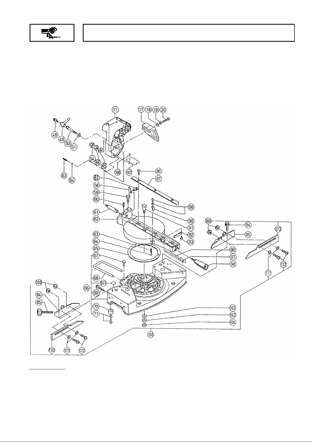
(1) Remove the M8 x 30 Machine Screw [20], and take off the Guard [17].
(2) Loosen the Clamp Lever [49], remove the M6 x 12 Machine Screw (w/washer and spring washer) [48], and
turn the left hand threaded M10 Bolt [50] clockwise to remove it from the Turn Table [62]. Then, remove the
M12 Cap Nut [54] and M12 Nut [46] from the Holder Shaft [61], disassemble Holder (A) [11], Spring (C) [63],
and Steel Ball [64] from the Holder Shaft [61]. At this time, the saw blade and slide sections are disassembled
from the Turn Table [62] together with Holder (A) [11].
(3) Remove the four M8 x 35 Bolts [94] (w/washers and spring washers), and disassemble Fence (A) [95] and
Fence (B) [84].
(4) Remove the M12 Nut [103] and the M12 Lock Nut [104], and disassemble the Turn Table [62] from the Base
Assembly [66].
(5) Disassemble the Side Handle [98], extract the D7 E-Type Retaining Ring [97], and extract the Shaft [96].
(6) The rear indicator [58], two Table Inserts [87], front Indicator [90] and Spacer [92] can be disassembled from
the Turn Table [62] by removing their retaining screws.
(7) The Holder [68] and five Base Rubbers [70] can be disassembled from the Base Assembly [66] by removing
their retaining bolts and screws.
B. Disassembly of the Hinge Shaft and Spring Section.
Tools Required
3 mm (.118") Hex. Bar Wrench
•
4 mm (.157") Hex. Bar Wrench
•
19 mm (3/4") Wrench
•
Wooden or Plastic Hammer
•
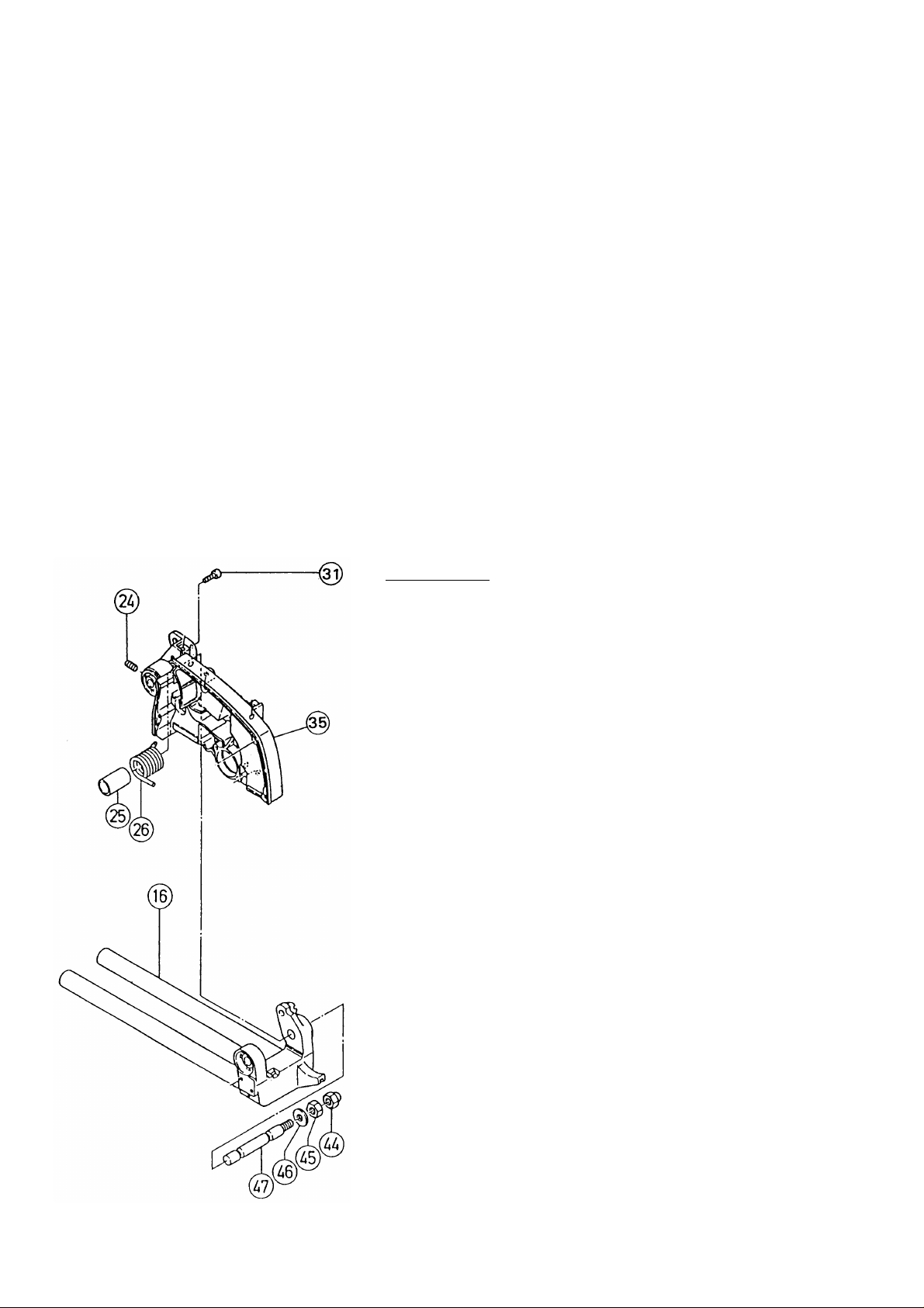
(2) Remove the two M6 x 16 Set screws [24] and the M5 x 10
Socket Bolt [31] from the Gear Case Assembly [35].
[CAUTION]
As the M5 x 10 Socket Bolt [31] acts as a stopper for the
Gear Case Assembly [35], be very careful to prevent the
Gear Case Assembly [35] from springing upward
suddenly when the bolt is removed.
(2) Remove the M12 Cap Nut [44] and the M12 Nut [45], and tap
gently on the end of the Hinge Shaft [47] with a wooden or
plastic hammer to extract it while supporting the Gear Case
Assembly [35]. At this time, the Gear Case Assembly [35]
can be taken off, and the Spring [26] and Sleeve [25] can be
removed.
--- 2 ---
C. Disassembly of the Holder (A), Hinge, Ball Bush, Bushes, and Related Parts:
Tools Required
Roll Pin Remover
•
Wooden or Plastic Hammer
•
Plus Head Screwdriver
•
4 mm (.157") Hex. Bar Wrench.
•
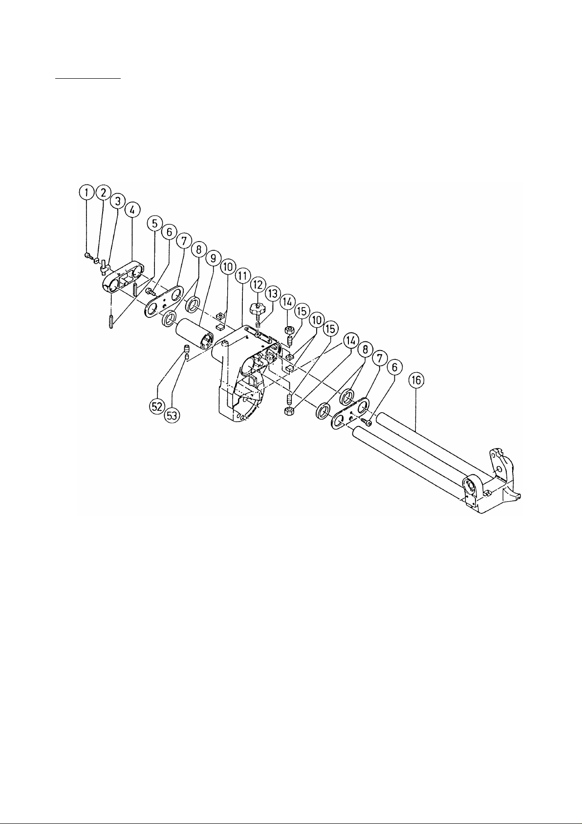
(1) Apply an appropriate roll pin remover to the end of each of the two D6 x 40 Roll Pins [5], and tap them gently
inward with a wooden or plastic hammer to disengage them. Then use the wooden or plastic hammer to
lightly tap the Support [4] outward to remove it from Slide Pipes (A) and (B). Next, loosen the M8 Knob Bolt
[12], and slide the Hinge [16] to extract it from Holder (A) [11].
(2) Remove the two M5 x 12 Machine Screws [6] which fix the two Packing Covers [7] to Holder (A) [11], and
remove the Packing Covers [7] and the four Felts [8]. Then, loosen the M8 x 8 Set Screw [52], and tap gently
on the Ball Brush [9] to remove it from Holder (A) [11].
(3) Finally, take out the four Brushes [10].
(When reassembling the four Bushes, please refer carefully to the instructions and precautuions listed in
Paragra 1-5-(4), Assembly of the Bushes.)
--- 3 ---
D. Disassembly of the Saw Cover, Safety Cover, Spindle Assembly, and Washers (C):
Tools Required
Plus Head Screwdriver
•
10 mm (.393") Box Wrench (standard accessory)
•
Wooden or Plastic Hammer
•
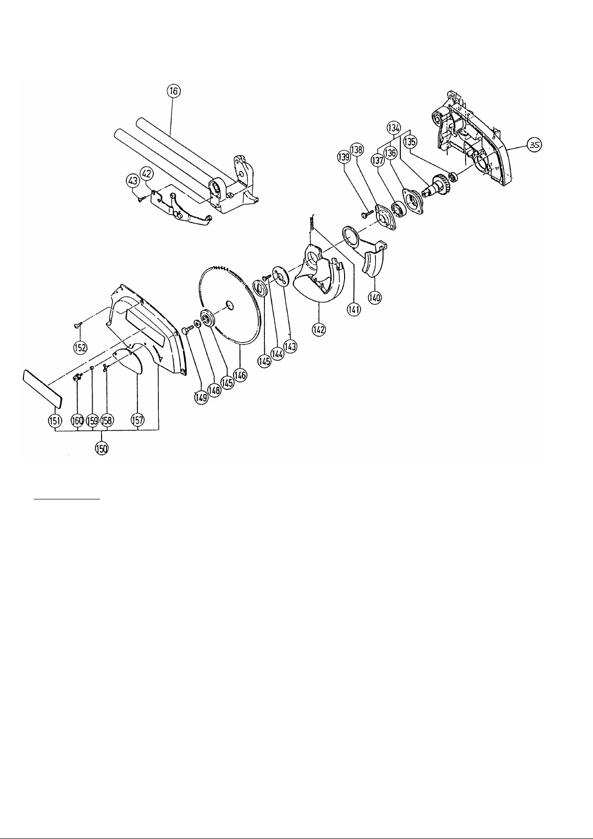
(1) Remove the four M5 x 10 Flat Head Screws [152], and take off the Saw Cover Assembly [150].
(2) Remove the M6 x 16 Flat Head Screw [43], and disassemble the Ring [42] from the Hinge [16].
(3) With the 10 mm (.393") Box Wrench, remove the M7 LH Bolt [149] and take off Washer (C) [145], the TCT
Saw Blade [146], and the inner Washer (C) [145] in the order.
(4) Remove the two M4 x 12 Flat Head Screws [144], and take off the Cover [143] and Safety Cover [142],
Return Spring [141] and Sub Cover [140].
(5) Remove the two M5 x 35 Flat Head Screws [139], and disassemble the Cover Holder [138] from the Gear
Case Assembly [35]. Then lightly tap on the end surface of the Gear Case Assembly [35] with the wooden or
plastic hammer to loosen and remove the Spindle Ass'y [134].
--- 4 ---
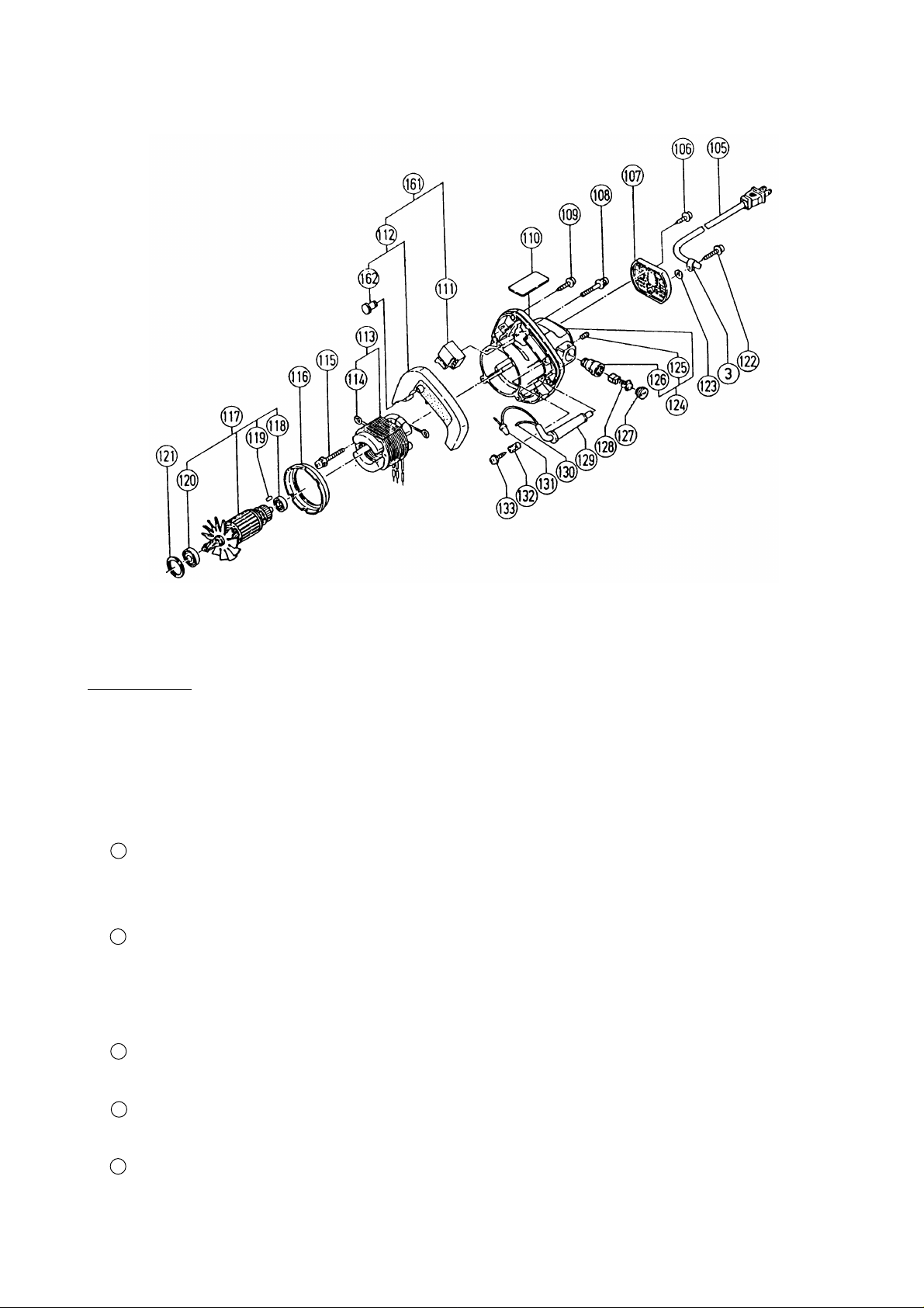
E. Disassembly of the Housing Assembly, Switch, Armature Assembly, and Stator Assembly:
Tools Required
Minus Screwdriver
•
Plus Head Screwdriver
•
Nippers
•
Wooden or Plastic Hammer
•
(1) Disassembly of the Armature:
1 Remove the Brush Caps [127], and take out the Carbon Brushes [128]. Then, remove the three M5 x 50
Machine Screws (w/washer and spring washer) [108]. The Housing Assembly [124] together with the
Handler Cover Assembly [112] can then be disassembled from the Gear Case Assembly [35].
2 Extract the Armature Assembly [117] from the Housing Assembly [124].
(2) Remove the three D4 x 25 Tapping Screws [109], and take off the Handle Cover Assembly [112]. The Switch
[111] can be removed after disconnecting the leadwires from the Stator Assembly [113] and Cord [105].
(3) Disassembly of the Stator Assembly:
1 Remove the D4 x 20 Tapping Screw [106] (w/washer) and the D4 x 25 Tapping Screw [122] (w/washer),
and disassembling the Tail Cover [107] from the Housing Assembly [124].
2 From the Brush Holders [126], disconnect the Brush Terminals [114] of the Stator Assembly [113]. Then,
cut off the single leadwire from the Stator Assembly [113] at the Connector [131] with the nippers.
3 Remove the two M5 x 60 Machine Screws [115] (w/washer and spring washer) which fix the Stator
Assembly [113], and then tap lightly on the Gear Case Assembly [35] mounting surface of the Housing
Assembly [124] with a wooden or plastic hammer to loosen and remove the Stator Assembly [113].
--- 5 ---
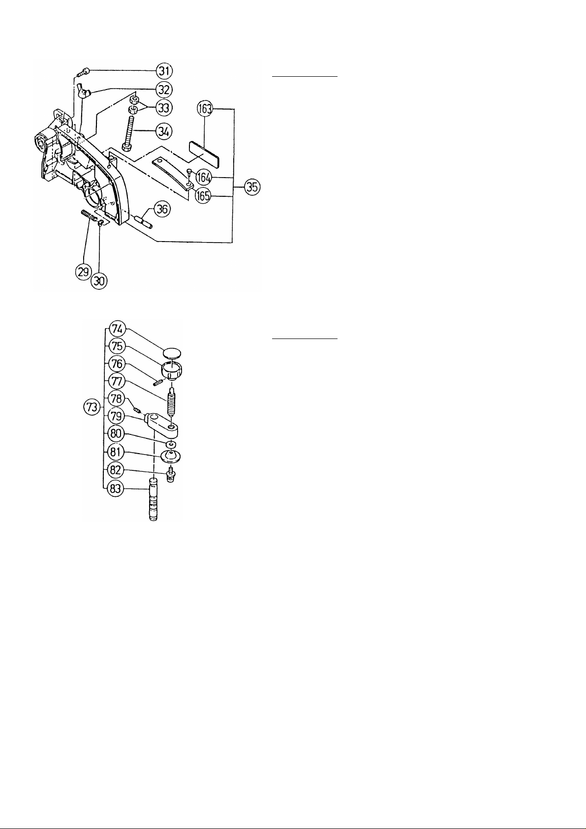
F. Disassembly of the Stopper Pin:
G. Disassembly of the Vise Assembly:
Tools Required
Pliers
•
(1) First take off the Safety Cover [142], and Return Spring
[141] by following the disassembly procedures in
Paragraph 1-1-D.
(2) With the pliers, extract the D7 E-Type Retaining Ring
[30], and disassemble the Stopper Pin [36] and the
Spring [29].
Tools Required
4 mm (.157") Hex. Bar Wrench
•
Roll Pin Remover
•
Plus Head Screwdriver
•
(1) Remove the M8 x 16 Set Screw [78], and extract the
Vise Shaft [83] from the Screw Holder [79].
(2) Finally, remove the D4 x 25 Roll Pin [76] and the
M6 x 10 Machine Screw (w/washer and spring washer)
[82], and take off the Knob [75] and the Vise Plate [81].
1-2. Reassembly
Reassembly can be accomplished by following the disassembly procedures in reverse. However, special
attention should be given to the following items.
(1) Prior to reassembly, measure the insulation resistance of the Armature Assembly, Stator Assembly, Switch and
other electrical components with a 500V DC Megohm Tester, and confirm that the insulation resistance of each
part is more than 5 MΩ. If the insulation resistance of any component is less than 5 MΩ, that component must
be replaced with a new one.
(2) If the M12 Nut [45] and M12 Cap Nut [44] of the Hinge Shaft [47] are fastened too tightly, it will interfere with
the smooth movement of the Gear Case Assembly [35]; if they are fastened too loosely, there will be
excessively play and vibration between the Gear Case Assembly [35] and the Hinge [16] which will result in
uneven and inefficient cutting. Carefully adjust the M12 Nut [45] and M12 Cap Nut [44] so that the Gear Case
Assembly [35] moves smoothly without excessive play or vibration.
(3) If the M12 Nut [55] and M12 Cap Nut [54], Spring (C) [63], and Steel Ball [64] of Holder Shaft [61] are
fastened tightly, it will interfere with the smooth movement of Holder (A) [11], and will result in ineffcient
believing of the saw blade. Carefully adjust the M12 Nut [55] and M12 Cap Nut [54] so that the Holder (A)
[11] slides smoothly without excessive play or vibration.
--- 6 ---
 Loading...