

Page 1
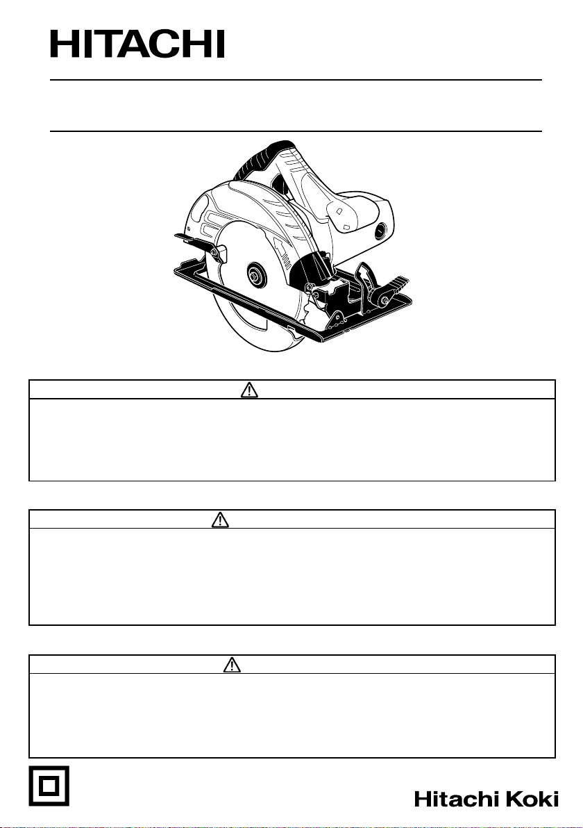
Model Circular saw
Modèle Scie circulaire
Modelo Sierra circular
C 7ST
SAFETY INSTRUCTIONS AND INSTRUCTION MANUAL
WARNING
IMPROPER OR UNSAFE use of this power tool can result in death or serious bodily
injury!
This manual contains important information about product safety. Please read and
understand this manual BEFORE operating the power tool. Please keep this manual
available for other users and owners before they use the power tool. This manual should
be stored in safe place.
INSTRUCTIONS DE SECURITE ET MODE D’EMPLOI
AVERTISSEMENT
Une utilisation INCORRECTE OU DANGEREUSE de cet outil motorisé peut entraîner la
mort ou de sérieuses blessures corporelles!
Ce mode d’emploi contient d’importantes informations à propos de la sécurité de ce
produit. Prière de lire et de comprendre ce mode d’emploi AVANT d’utiliser l’outil
motorisé. Garder ce mode d’emploi à la disponibilité des autres utilisateurs et propriétaires
avant qu’ils utilisent l’outil motorisé. Ce mode d’emploi doit être conservé dans un
endroit sûr.
INSTRUCCIONES DE SEGURIDAD Y MANUAL DE INSTRUCCIONES
ADVERTENCIA
¡La utilización INAPROPIADA O PELIGROSA de esta herramienta eléctrica puede
resultar en lesiones de gravedad o la muerte!
Este manual contiene información importante sobre la seguridad del producto. Lea y
comprenda este manual ANTES de utilizar la herramienta eléctrica. Guarde este manual
para que puedan leerlo otras personas antes de utilizar la herramienta eléctrica. Este
manual debe ser guardado en un lugar seguro.
DOUBLE INSULATION
DOUBLE ISOLATION
AISLAMIENTO DOBLE
Page 2

English
IMPORTANT SAFETY INFORMATION .............. 3
MEANINGS OF SIGNAL WORDS ...................... 3
MEANINGS OF SYMBOLS ................................. 3
SAFETY .................................................................... 3
GENERAL POWER TOOL SAFETY
WARNINGS .................................................... 3
SPECIFIC SAFETY RULES AND SYMBOLS ....... 4
DOUBLE INSULATION FOR SAFER
OPERATION ................................................... 8
FUNCTIONAL DESCRIPTION .................................... 9
NAME OF PARTS .................................................. 9
SPECIFICATIONS .................................................. 9
CONTENTS
Page
ASSEMBLY AND OPERATION ............................... 10
APPLICATIONS ................................................... 10
PRIOR TO OPERATION ....................................... 10
ADJUSTING THE SAW PRIOR TO USE ............. 11
CUTTING PROCEDURES .................................... 13
MOUNTING AND DISMOUNTING THE
SAW BLADE ................................................. 14
MAINTENANCE AND INSPECTION ....................... 16
ACCESSORIES ......................................................... 18
STANDARD ACCESSORIES ............................... 18
OPTIONAL ACCESSORIES ................................. 18
PARTS LIST .............................................................. 53
Page
Français
INFORMATIONS IMPORTANTES
DE SÉCURITÉ ............................................... 19
SIGNIFICATION DES MOTS
D’AVERTISSEMENT .................................... 19
SIGNIFICATION DES SYMBOLES ...................... 19
SECURITE ................................................................ 19
AVERTISSEMENTS DE SÉCURITÉ GÉNÉRAUX
CONCERNANT LES OUTILS ÉLECTRIQUES ..
RÈGLES DE SÉCURITÉ SPÉCIFIQUES ET
SYMBOLES .................................................. 21
DOUBLE ISOLATION POUR UN
FONCTIONNEMENT PLUS SUR ................. 25
DESCRIPTION FONCTIONNELLE ........................... 26
NOM DES PARTIES ............................................ 26
SPECIFICATIONS ................................................ 26
TABLE DES MATIERES
Page
Español
INFORMACIÓN IMPORTANTE SOBRE
SEGURIDAD ................................................. 36
SIGNIFICADO DE LAS PALABRAS DE
SEÑALIZACIÓN ............................................ 36
SIGNIFICADO DE SÍMBOLOS ............................ 36
SEGURIDAD ............................................................. 36
ADVERTENCIAS DE SEGURIDAD GENERAL
DE LA HERRAMIENTA ELÉCTRICA ............ 36
NORMAS Y SÍMBOLOS ESPECÍFICOS DE
SEGURIDAD ................................................. 38
AISLAMIENTO DOBLE PARA OFRECER UNA
OPERACIÓN MÁS SEGURA ........................ 42
DESCRIPCIÓN FUNCIONAL .................................... 43
NOMENCLATURA ............................................... 43
ESPECIFICACIONES ............................................ 43
Página
19
ÍNDICE
ASSEMBLAGE ET FONCTIONNEMENT ................ 27
APPLICATIONS ................................................... 27
AVANT L’UTILISATION ...................................... 27
RÉGLAGE DE LA SCIE AVANT
L’UTILISATION ............................................. 28
PROCEDURES DE COUPE .................................. 30
MONTAGE ET DÉMONTAGE DE LA LAME DE
SCIE .............................................................. 31
ENTRETIEN ET INSPECTION .................................. 33
ACCESOIRES ........................................................... 35
ACCESSOIRES STANDARD ............................... 35
ACCESSOIRES EN OPTION ................................ 35
LISTE DES PIECES ................................................... 53
MONTAJE Y OPERACIÓN ...................................... 44
APLICACIONES ................................................... 44
ANTES DE LA OPERACIÓN ................................ 44
AJUSTE DE LA SIERRA ANTES DE
UTILIZARLA .................................................. 45
PROCEDIMIENTOS DE CORTE .......................... 47
MONTAJE Y DESMONTAJE DE LA
CUCHILLA DE LA SIERRA ........................... 48
MANTENIMIENTO E INSPECCIÓN ........................ 50
ACCESORIOS ........................................................... 52
ACCESORIOS ESTÁNDAR ................................. 52
ACCESORIOS OPCIONALES .............................. 52
LISTA DE PIEZAS .................................................... 53
Page
Página
2
Page 3
English
IMPORTANT SAFETY INFORMATION
Read and understand all of the safety precautions, warnings and operating instructions in the Instruction Manual
before operating or maintaining this power tool.
Most accidents that result from power tool operation and maintenance are caused by the failure to observe basic
safety rules or precautions. An accident can often be avoided by recognizing a potentially hazardous situation
before it occurs, and by observing appropriate safety procedures.
Basic safety precautions are outlined in the “SAFETY” section of this Instruction Manual and in the sections which
contain the operation and maintenance instructions.
Hazards that must be avoided to prevent bodily injury or machine damage are identified by WARNINGS on the
power tool and in this Instruction Manual.
NEVER use this power tool in a manner that has not been specifically recommended by HITACHI.
MEANINGS OF SIGNAL WORDS
WARNING indicates a potentially hazardous situations which, if ignored, could result in death or serious injury.
CAUTION indicates a potentially hazardous situations which, if not avoided, may result in minor or moderate
injury, or may cause machine damage.
NOTE emphasizes essential information.
MEANINGS OF SYMBOLS
Symbols
WARNING
The following show symbols used for the machine. Be sure that you understand their meaning before use.
Read all safety warnings and all instructions.
Failure to follow the warnings and instructions
may result in electric shock, fire and/or serious
injury.
Always wear eye protection.
Always wear hearing protection.
SAFETY
GENERAL POWER TOOL SAFETY WARNINGS
WARNING:
Read all safety warnings and all instructions.
Failure to follow the warnings and instructions may result in electric shock, fire and/or serious injury.
Save all warnings and instructions for future reference.
The term “power tool” in the warnings refers to your mains-operated (corded) power tool or battery-operated
(cordless) power tool.
1) Work area safety
a) Keep work area clean and well lit.
Cluttered or dark areas invite accidents.
b) Do not operate power tools in explosive
atmospheres, such as in the presence of
flammable liquids, gases or dust.
Power tools create sparks which may ignite
the dust or fumes.
c) Keep children and bystanders away while
operating a power tool.
Distractions can cause you to lose control.
2) Electrical safety
a) Power tool plugs must match the outlet.
Never modify the plug in any way.
Do not use any adapter plugs with earthed
(grounded) power tools.
Unmodified plugs and matching outlets will
reduce risk of electric shock.
b) Avoid body contact with earthed or grounded
surfaces such as pipes, radiators, ranges and
refrigerators.
3
Page 4

English
There is an increased risk of electric shock if
your body is earthed or grounded.
c) Do not expose power tools to rain or wet
conditions.
Water entering a power tool will increase the
risk of electric shock.
d) Do not abuse the cord. Never use the cord for
carrying, pulling or unplugging the power tool.
Keep cord away from heat, oil, sharp edges
or moving parts.
Damaged or entangled cords increase the risk
of electric shock.
e) When operating a power tool outdoors, use
an extension cord suitable for outdoor use.
Use of a cord suitable for outdoor use reduces
the risk of electric shock.
f) If operating a power tool in a damp location
is unavoidable, use a residual current device
(RCD) protected supply.
Use of an RCD reduces the risk of electric shock.
3) Personal safety
a) Stay alert, watch what you are doing and use
common sense when operating a power tool.
Do not use a power tool while you are tired
or under the influence of drugs, alcohol or
medication.
A moment of inattention while operating power
tools may result in serious personal injury.
b) Use personal protective equipment. Always
wear eye protection.
Protective equipment such as dust mask, nonskid safety shoes, hard hat, or hearing
protection used for appropriate conditions
will reduce personal injuries.
c) Prevent unintentional starting. Ensure the
switch is in the off-position before connecting
to power source and/or battery pack, picking
up or carrying the tool.
Carrying power tools with your finger on the
switch or energising power tools that have
the switch on invites accidents.
d) Remove any adjusting key or wrench before
turning the power tool on.
A wrench or a key left attached to a rotating part
of the power tool may result in personal injury.
e) Do not overreach. Keep proper footing and
balance at all times.
This enables better control of the power tool
in unexpected situations.
f) Dress properly. Do not wear loose clothing
or jewellery. Keep your hair, clothing and
gloves away from moving parts.
Loose clothes, jewellery or long hair can be
caught in moving parts.
g) If devices are provided for the connection of
dust extraction and collection facilities, ensure
these are connected and properly used.
Use of dust collection can reduce dust-related
hazards.
4
4) Power tool use and care
a) Do not force the power tool. Use the correct
power tool for your application.
The correct power tool will do the job better
and safer at the rate for which it was designed.
b) Do not use the power tool if the switch does
not turn it on and off.
Any power tool that cannot be controlled with
the switch is dangerous and must be repaired.
c) Disconnect the plug from the power source
and/or the battery pack from the power tool
before making any adjustments, changing
accessories, or storing power tools.
Such preventive safety measures reduce the
risk of starting the power tool accidentally.
d) Store idle power tools out of the reach of
children and do not allow persons unfamiliar
with the power tool or these instructions to
operate the power tool.
Power tools are dangerous in the hands of
untrained users.
e) Maintain power tools. Check for
misalignment or binding of moving parts,
breakage of parts and any other condition
that may affect the power tool’s operation.
If damaged, have the power tool repaired
before use.
Many accidents are caused by poorly
maintained power tools.
f) Keep cutting tools sharp and clean.
Properly maintained cutting tools with sharp
cutting edges are less likely to bind and are
easier to control.
g) Use the power tool, accessories and tool bits
etc. in accordance with these instructions,
taking into account the working conditions
and the work to be performed.
Use of the power tool for operations different
from those intended could result in a
hazardous situation.
5) Service
a) Have your power tool serviced by a qualified
repair person using only identical
replacement parts.
This will ensure that the safety of the power
tool is maintained.
SPECIFIC SAFETY RULES AND SYMBOLS
1. DANGER: Keep hands away from cutting area
and the blade. Keep your second hand on auxiliary
handle, or motor housing.
If both hands are holding the saw, they cannot be
cut by the blade.
2. Do not reach underneath the workpiece.
The guard cannot protect you from the blade below
the workpiece.
Page 5
English
3. Adjust the cutting depth to the thickness of the
workpiece.
Less than a full tooth of the blade teeth should be
visible below the workpiece.
4. NEVER hold piece being cut in your hands or
across your leg. Secure the workpiece to a stable
platform.
It is important to support the work properly to
minimize body exposure, blade binding, or loss of
control.
5. Hold power tool by insulated gripping surfaces
when performing an operation where the cutting
tool may contact hidden wiring or its own cord.
Contact with a “live” wire will also make exposed
metal parts of the power tool “live” and shock the
operator.
6. When ripping always use a rip fence or straight
edge guide.
This improves the accuracy of cut and reduces the
chance of blade binding.
7. Always use blades with correct size and shape
(diamond versus round) arbour holes.
Blades that do not match the mounting hardware
of the saw will run eccentrically, causing loss of
control.
8. Never use damaged or incorrect blade washers
or bolt.
11. When blade is binding, or when interrupting a cut
for any reason, release the trigger and hold the
saw motionless in the material until the blade
comes to a complete stop. Never attempt to
remove the saw from the work or pull the saw
backward while the blade is in motion or
KICKBACK may occur.
Investigate and take corrective actions to eliminate
the cause of blade binding.
12. When restarting a saw in the workpiece, center
the saw blade in the kerf and check that saw teeth
are not engaged into the material.
If saw blade is binding, it may walk up or KICKBACK
from the workpiece as the saw is restarted.
13. Support large panels to minimize the risk of blade
pinching and KICKBACK.
Large panels tend to sag under their own weight.
Supports must be placed under the panel on both
sides, near the line of cut and near the edge of the
panel as shown in Fig. 1.
To minimize the risk of blade pinching and
kickback. When cutting operation requires the
resting of the saw on the work piece, the saw shall
be rested on the larger portion and the smaller
piece cut off.
The blade washers and bolt were specially
designed for your saw, for optimum performance
and safety of operation.
9. Causes and Operator Prevention of Kickback:
Kickback is a sudden reaction to a pinched, bound
or misaligned saw blade, causing an uncontrolled
saw to lift up and out of the workpiece toward the
operator.
When the blade is pinched or bound tightly by the
kerf closing down, the blade stalls and the motor
reaction drives the unit rapidly back toward the
operator.
If the blade becomes twisted or misaligned in the
cut, the teeth at the back edge of the blade can dig
into the top surface of the wood causing the blade
to climb out of the kerf and jump back toward the
operator.
Kickback is the result of saw misuse and/or
incorrect operating procedures or conditions and
can be avoided by taking proper precautions as
given below:
10. Maintain a firm grip with both hands on the saw
and position your arms to resist kickback forces.
Position your body to either side of the blade, but
not in line with the blade.
KICKBACK could cause the saw to jump
backwards, but kickback forces can be controlled
by the operator, if proper precautions are taken.
14. Do not use dull or damaged blades.
Unsharpened or improperly set blades produce
narrow kerf causing excessive friction, blade
binding and KICKBACK.
15. Blade depth and bevel adjusting locking levers
must be tight and secure before making cut.
If blade adjustment shifts while cutting, it may
cause binding and KICKBACK.
To avoid kickback, do support board
or panel near the cut.
Fig. 1
Don't support board or panel away
from the cut.
Fig. 2
5
Page 6

English
16. Use extra caution when making a “Plunge Cut”
into existing walls or other blind areas.
The protruding blade may cut objects that can
cause KICKBACK.
NEVER place your hand or fingers behind the saw.
If kickback occurs, the saw could easily jump
backwards over your hand, possibly causing
Operate with proper hand support, proper
workpiece support, and supply cord routing away
from the work area.
WARNING: It is important to support the work
piece properly and to hold the saw firmly to prevent
loss of control which could cause personal injury.
Fig. 4 illustrates typical hand support of the saw.
severe injury.
Fig. 3
17. Check lower guard for proper closing before each
use. Do not operate the saw if lower guard does
not move freely and close instantly. Never clamp
or tie the lower guard into the open position.
If saw is accidentally dropped, lower guard may
be bent.
Raise the lower guard with the Retracting Handle
and make sure it moves freely and does not touch
the blade or any other part, in all angles and depths
of cut.
18. Check the operation of the lower guard spring. If
the guard and the spring are not operating
properly, they must be serviced before use.
Lower guard may operate sluggishly due to
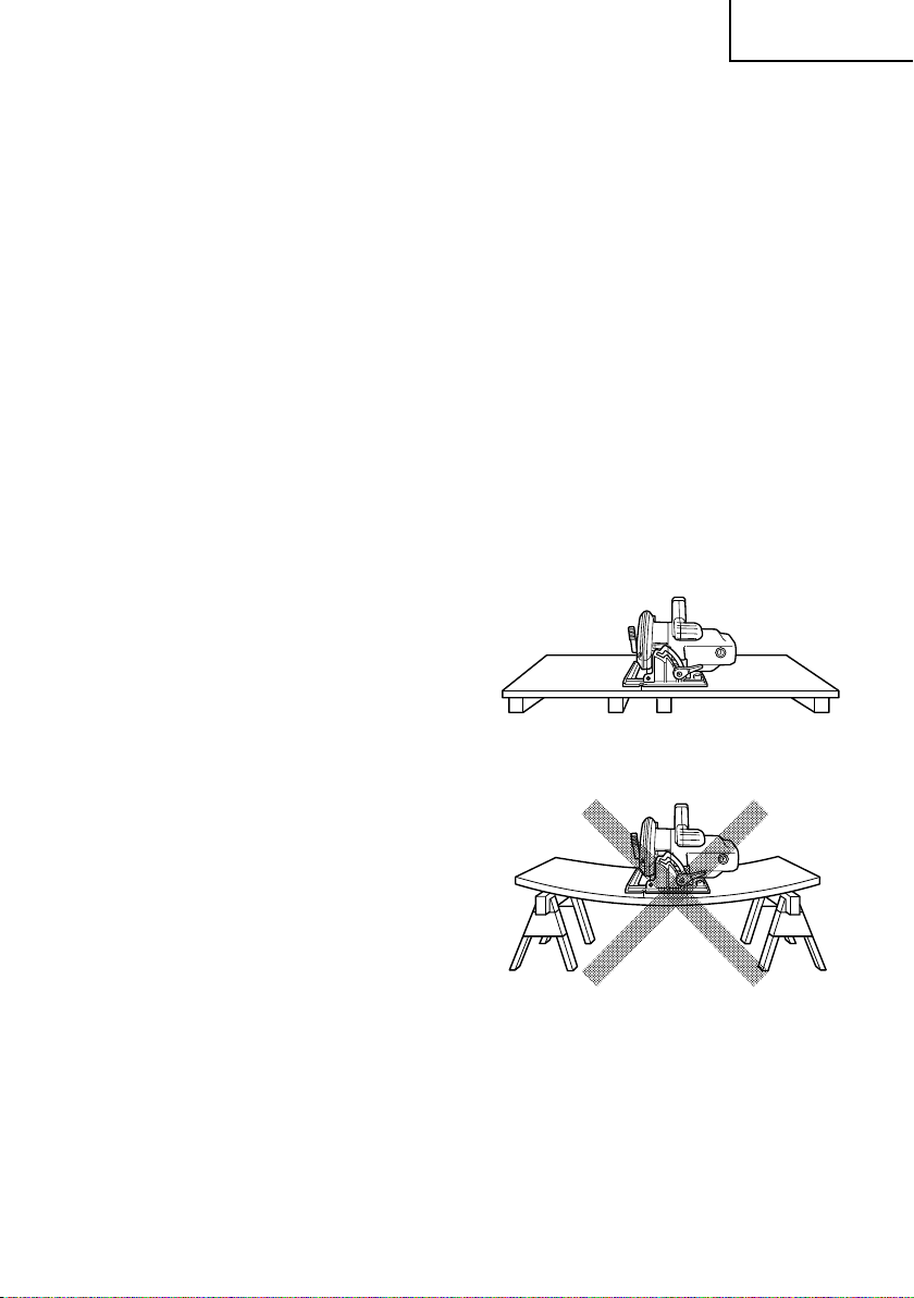
24. Place the wider portion of the saw base on that
part of the work piece which is solidly supported,
not on the section that will fall off when the cut is
made.
As examples, Fig. 5 illustrates the RIGHT way to
cut off the end of board, and Fig. 6 the WRONG
way. If the work piece is short or small, clamp it
down.
DON’T TRY TO HOLD SHORT PLACES BY HAND!
damaged parts, gummy deposits, or a build-up of
debris.
19. Lower guard should be retracted manually only
for special cuts such as “Plunge Cuts” and
“Compound Cuts.” Raise lower guard by
Retracting Handle and as soon as blade enters the
material, the lower guard must be released.
For all other sawing, the lower guard should
operate automatically.
20. Always observe that the lower guard is covering
the blade before placing saw down on bench or
floor.
An unprotected, coasting blade will cause the saw
to walk backwards, cutting whatever is in its path.
Be aware of the time it takes for the blade to stop
after switch is released.
21. Adjustments. Before cutting be sure depth and
bevel adjustments are tight.
22. Avoid cutting nails. Inspect for and remove all nails
from work piece before cutting.
23. When operating the saw, keep the cord away from
the cutting area and position it so that it will not
be caught on the workpiece during the cutting
operation.
6
A TYPICAL ILLUSTRATION OF
PROPER HAND SUPPORT
WORKPIECE SUPPORT,
AND SUPPLY CORD ROUTING.
Fig. 4
Fig. 5
Fig. 6
Page 7

English
25. Never attempt to saw with the circular saw held
upside down in a vise.
This is extremely dangerous and can lead to
serious accidents. (Fig. 7)
34. Do not run the saw while carrying it at your side.
35. Keep all screws, bolts and covers tightly in place.
Keep all screws, bolts, and plates tightly mounted.
Check their condition periodically.
36. Do not use power tools if the plastic housing or
handle is cracked.
Cracks in the tool’s housing or handle can lead to
electric shock. Such tools should not be used until
repaired.
37. Blades and accessories must be securely mounted
to the tool.
Prevent potential injuries to yourself or others.
Blades, cutting implements and accessories which
have been mounted to the tool should be secure
and tight.
38. Never use a tool which is defective or operating
abnormally.
Fig. 7
26. Before setting the tool down after completing a
cut, be sure that the lower (telescoping) guard has
closed and the blade has come to a complete stop.
27. Never touch moving parts.
Never place your hands, fingers or other body
parts near the tool’s moving parts.
28. Never operate without all guards in place.
Never operate this tool without all guards or safety
features in place and in proper working order. If
maintenance or servicing requires the removal of
a guard or safety feature, be sure to replace the
guard or safety feature before resuming operation
of the tool.
29. Use right tool.
Don’t force small tool or attachment to do the job
of a heavy-duty tool.
Don’t use tool for purpose not intended —for
example— don’t use circular saw for cutting tree
limbs or logs.
30. Never use a power tool for applications other than
those specified.
Never use a power tool for applications other than
If the tool appears to be operating unusually,
making strange noises, or otherwise appears
defective, stop using it immediately and arrange
for repairs by a Hitachi authorized service center.
39. Carefully handle power tools.
Should a power tool be dropped or struck against
hard materials inadvertently, it may be deformed,
cracked, or damaged.
40. Do not wipe plastic parts with solvent.
Solvents such as gasoline, thinner benzine, carbon
tetrachloride, and alcohol may damage and crack
plastic parts. Do not wipe them with such solvents.
Wipe plastic parts with a soft cloth lightly
dampened with soapy water and dried thoroughly.
41. Never wear gloves made of material liable to roll
up such as cotton, wool, cloth or string, etc.
42. Definitions for symbols.
V ............ volts
Hz .......... hertz
A ............ amperes
no .......... no load speed
---/min ... revolutions per minute
those specified in the Instruction Manual.
31. Handle tool correctly.
Operate the tool according to the instructions
provided herein. Do not drop or throw the tool.
Never allow the tool to be operated by children,
individuals unfamiliar with its operation or
unauthorized personnel.
32. Keep motor air vent clean.
The tool’s motor air vent must be kept clean so
that air can freely flow at all times. Check for dust
build-up frequently.
33. Operate power tools at the rated voltage.
Operate the power tool at voltages specified on
their nameplates.
If using the power tool at a higher voltage than
the rated voltage, it will result in abnormally fast
motor revolution and may damage the unit and
burn out the motor.
......... Class II Construction
.......... alternating or direct current
7
Page 8

English
䡬
DOUBLE INSULATION FOR SAFER
OPERATION
To ensure safer operation of this power tool, HITACHI
has adopted a double insulation design. “Double
insulation” means that two physically separated
insulation systems have been used to insulate the
electrically conductive materials connected to the power
supply from the outer frame handled by the operator.
Therefore, either the symbol “ ” or the words “Double
insulation” appear on the power tool or on the nameplate.
Although this system has no external grounding, you
must still follow the normal electrical safety precautions
given in this Instruction Manual, including not using the
power tool in wet environments.
To keep the double insulation system effective, follow
these precautions:
Only HITACHI AUTHORIZED SERVICE CENTER
should disassemble or assemble this power tool,
and only genuine HITACHI replacement parts
should be installed.
䡬
Clean the exterior of the power tool only with a
soft cloth moistened with soapy water, and dry
thoroughly.
Never use solvents, gasoline or thinners on plastic
components; otherwise the plastic may dissolve.
SAVE THESE INSTRUCTIONS
AND
MAKE THEM AVAILABLE TO OTHER USERS
AND
OWNERS OF THIS TOOL!
8
Page 9

English
FUNCTIONAL DESCRIPTION
NOTE:
The information contained in this Instruction Manual is designed to assist you in the
safe operation and maintenance of the power tool.
NEVER operate, or attempt any maintenance on the tool unless you have first read and
understood all safety instructions contained in this manual.
Some illustrations in this Instruction Manual may show details or attachments that differ
from those on your own power tool.
NAME OF PARTS
Handle
Blade Cover
Lever
(Retracting
Handle)
Base
Saw Blade
Lower Guard
Switch
Gear Cover
Lock Lever
Lever (A)
Fig. 8
SPECIFICATIONS
Motor Single-Phase, Series Commutator Motor
Power Source Single-Phase 120V AC 60Hz, 120V DC
Max. Cutting Depth 2-7/16" (62mm)
Current 15 A
No-Load Speed 6,000/min.
Weight (without cord) 9.5 lbs (4.3 kg)
9
Page 10
English
ASSEMBLY AND OPERATION
APPLICATIONS
䡬 Cutting Various types of wood.
PRIOR TO OPERATION
1. Power source
Ensure that the power source to be utilized conforms to the power source requirements
specified on the product nameplate.
2. Power switch
Ensure that the switch is in the OFF position. If the plug is connected to a receptacle
while the switch is in the ON position, the power tool will start operating immediately
and can cause serious injury.
3. Extension cord
When the work area is far away from the power source, use an extension cord of sufficient
thickness and rated capacity. The extension cord should be kept as short as practicable.
WARNING: Damaged cord must be replaced or repaired.
4. Check the receptacle
If the receptacle only loosely accepts the plug, the receptacle must be repaired. Contact
a licensed electrician to make appropriate repairs.
If such a faulty receptacle is used, it may cause overheating, resulting in a serious hazard.
5. Confirming condition of the environment:
Confirm that the work site is placed under appropriate conditions conforming to
prescribed precautions.
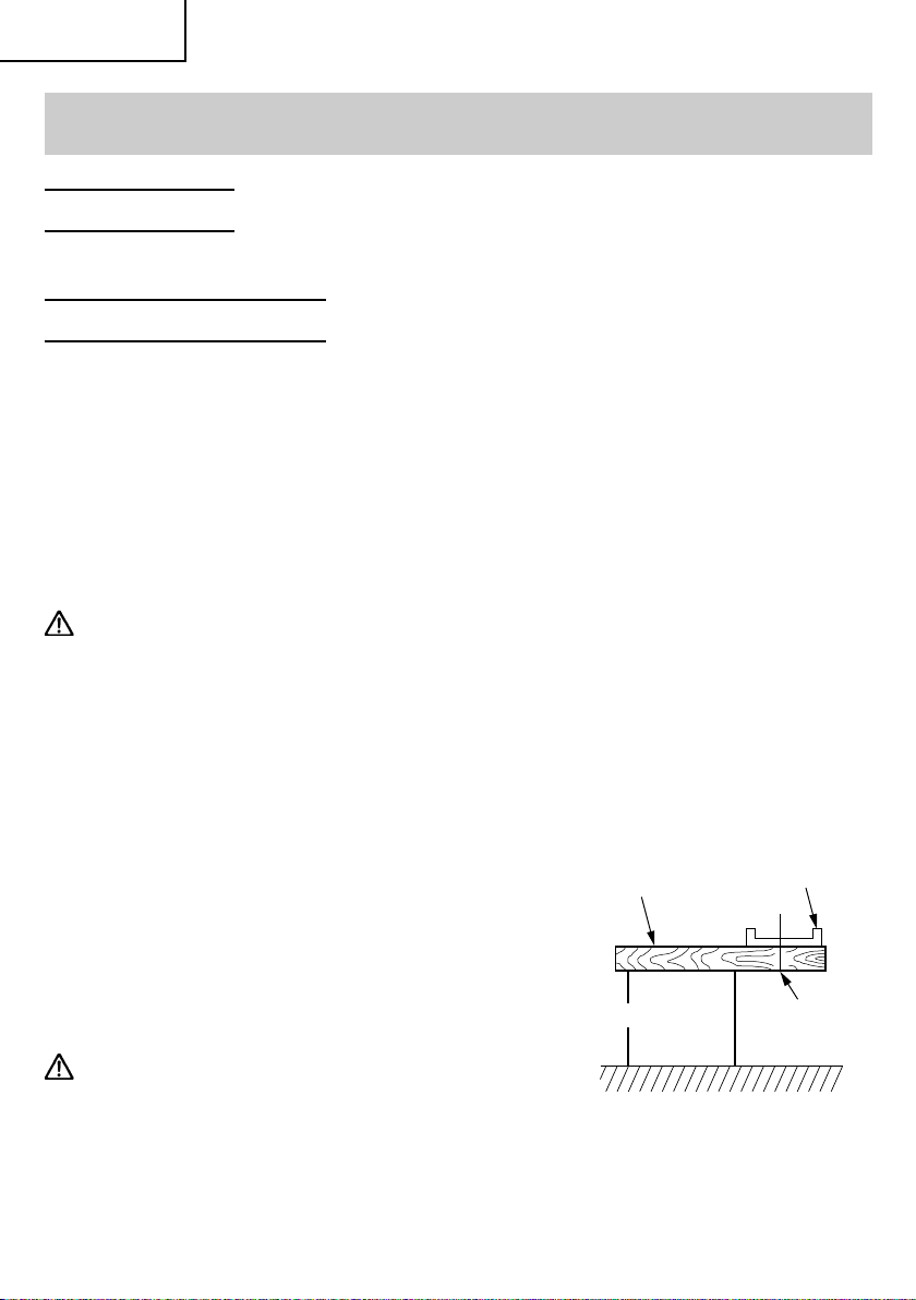
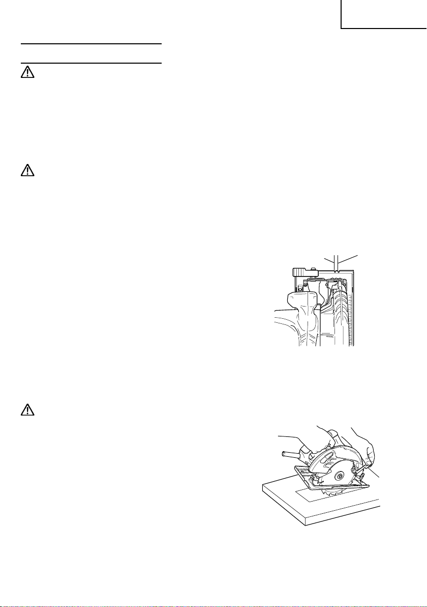
6. Prepare a wooden workbench (Fig. 9)
Since the saw blade will extend beyond the
lower surface of the work piece, place the work
piece on a workbench when cutting. If a square
block is utilized as a workbench, select level
ground to ensure it is properly stabilized. An
unstable workbench will result in hazardous
operation.
CAUTION:
To avoid possible accident, always ensure that
the portion of work piece remaining after
cutting is securely anchored or held in position.
10
Work piece
Workbench
Saw Blade
Fig. 9
Base
Page 11

English
7. Check if lever (A) is tightened.
If the lever (A) to adjust cutting depth (Fig. 10) and angle of inclination (Fig. 11) are
loose, injury can result. Make sure that they are tightened securely.
8. Check performance of lower guard
WARNING: Make absolutely sure that the safety cover is not fixed. Also, check and
see if it can move smoothly. If the saw blade is kept exposed injury can result.
The lower guard (refer to Fig. 8) serves to protect your body from coming into contact with
the saw blade. Make absolutely certain that the cover smoothly performs to cover the saw
blade. If the lower guard should not move smoothly, never use it without repairing it.
In such a case, get in touch with the store where you bought the circular saw or the
HITACHI Authorized Service Center for necessary repair.
9. Eye protection
When you use the tool, make certain that you wear eye protection.
10. Check if saw blade is tightened
Refer to [mounting and dismounting the saw blade] in Page 14, and make sure that the
flange bolt is tightened securely.
ADJUSTING THE SAW PRIOR TO USE
WARNING:
To avoid serious accidents, ensure the switch
is in OFF position, and disconnect the plug from
the receptacle.
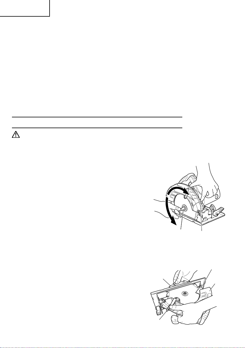
1. Adjusting the cutting depth (Fig. 10)
WARNING:
If the lever (A) is loose, injury can result. Tighten
it securely after adjustment.
To adjust cutting depth, loosen the lever (A)
and, while holding the base with one hand,
move the main body up and down to obtain
the prescribed cutting depth. After adjusting to
the prescribed cutting depth, tighten the lever
(A) securely.
Tighten
Lever (A)
Loosen
Base
Fig. 10
11
Page 12

English
2. Adjusting the angle of inclination
WARNING:
If the lever (A) is loose, injury can result. Tighten
it securely after adjustment.
You can incline saw blade from 0˚ to a maximun
angle of 45˚ in relation to the base.
As shown in Fig. 11 by loosing the lever (A) on
the bevel scale, the saw blade may be inclined
to an angle of 45˚ in relation to the base.
Always ensure that the lever (A) is thoroughly
tightened after making the desired adjustment.
3. Regulating the guide (Rip fence) (Fig. 12,
13)
........................................ Optional Accessory
Install the wing bolt (B) and lock spring on the
base. Insert the guide into the base, move it
left and right and adjust the cutting position.
Tighten the wing bolt (B) and fix the guide. The
guide can be installed either from the left or
the right side of the main body.
Lever (A)
0˚ – 45˚
Fig. 11
Wing
Bolt (B)
Lock
Spring
Base
Fig. 12
Wing Bolt (B), Lock Spring
Base
Guide
(Rip Fence)
Fig. 13
12
Page 13
English
CUTTING PROCEDURES
WARNING:
● Never touch the moving parts.
● Should the saw blade be stopped or make an abnormal noise during operation, turn
off the switch immediately.
● Don't remove circular saw from work piece during a cut while the saw blade is moving.
● Wear eye protection.
● Avoid cutting any material like metal, etc., that give off sparks.
● Do not use any abrasive wheels.
CAUTION:
● Always take care in preventing the power cord from coming near the revolving saw
blade.
● Before starting to saw, ensure that the saw blade has reached full speed revolution.
1. Place the saw body (base) on the work piece,
and as in Fig. 14 align the intended line of cut
with the saw blade, using the notch at the front
of the base. This relationship of base to work
pieces should remain unchanged regardless of
the inclination of the base.
2. The switch should be turned to the ON position
before the saw blade comes into contact with
the work piece. The switch is turned ON when
the trigger is pulled by one’s finger, and is
turned OFF when the trigger is released.
3. Moving the saw straight at a constant speed
will produce optimum cutting.
When
Inclined 45°
Fig. 14
When not
Inclined
[POCKET CUTTING]
WARNING:
● To avoid serious accident, ensure the switch
is OFF position, and disconnect the plug from
the receptacle before any adjustment.
● Never tie or wedge the lower guard in a raised
position.
1. Mark the desired cutting area clearly with lines
all side. (See Fig. 15)
2. Set depth adjustment according to material to
be cut.
3. Push the lever all the way back so the blade is
exposed as shown in Fig. 15.
4. Tilt saw forward and align the notch (Fig. 14)
with the pre-marked guide line.
Lever
Fig. 15
13
Page 14
English
5. Release the lever. When the lower guard contacts the work piece surface, it will be in
proper position to open freely when cutting is commencend.
6. Holding the saw in position, with the blade not contacting the work piece surface, pull
the trigger.
7. After the saw has reached full speed, gradually lower rear end of the saw until its base
rests on the work surface.
8. Advance saw along the cutting line up to the corner.
9. Release trigger and allow blade to stop completely before withdrawing the blade from
the work piece.
䡩 Never under any circumstances pull the saw backwards while the blade is in motion, as
kickback may result.
10. Use a jig saw or hand saw to cut the corners out clean.
11. When starting each new cut, repeat as above.
MOUNTING AND DISMOUNTING THE SAW BLADE
WARNING: To avoid serious accident ensure the switch is in the OFF position, and
disconnect the plug from the receptacle.
1. Dismounting the saw blade
(1) Set the cutting volume at maximum, and place
the Circular Saw as shown in Fig. 16.
(2) Depress the lock lever, lock the spindle, and
remove the hexagonal-flange bolt and
washer(B) with the wrench.
(3) While holding the lever to keep the lower guard
fully retracted into the blade cover, remove the
saw blade. (Fig. 17)
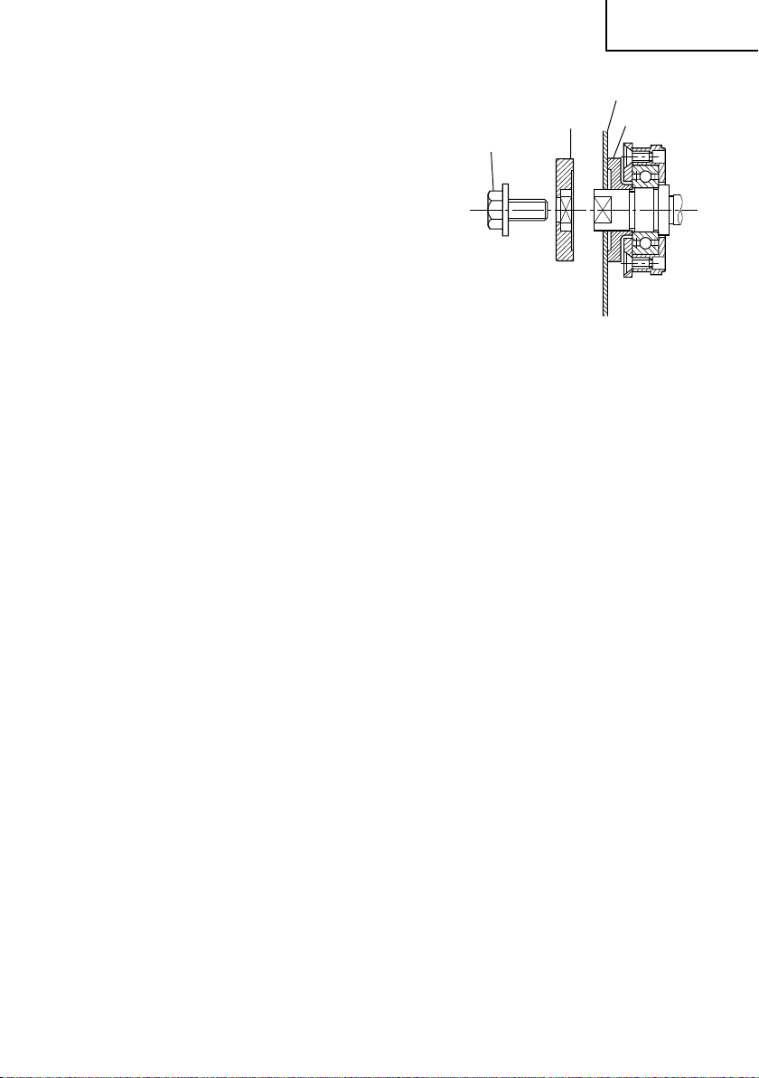
2. Mounting the saw blade
(1) Thoroughly remove any sawdust which has
accumulated on the spindle, bolt and washers.
(2) For mounting saw blade, the concave sides of
both washers (A) and (B) must be fitted to the
saw blade sides. Mount the saw blade on the
spindle, and finally affix washer (B) (See Fig.
18)
(3) To assure proper rotation direction of the saw
blade, the arrow direction on the saw blade
must coincide with the arrow direction on the
blade cover.
Tighten
Loosen
Saw Blade
Wrench
Fig. 16
Lock Lever
Lower Guard
Blade
Cover
Lever
14
Fig. 17
Page 15
English
(4) Using the fingers, tighten the hexagonal bolt
retaining the saw blade as much as possible.
Then depress the lock lever, lock the spindle,
and thoroughly tighten the bolt.
(5) Confirm that the lock lever is in the original
position.
Hexagonal
Flange Bolt
Washer (B)
Fig. 18
Saw Blade
Washer (A)
15
Page 16

English
MAINTENANCE AND INSPECTION
WARNING: To avoid serious accident, ensure the switch is in the OFF position and
disconnect the plug from the receptacle during maintenance and
inspection.
1. Inspecting the saw blade:
Since use of a dull saw blade will degrade efficiency and cause possible motor
malfunction, sharpen or replace the saw blade as soon as abrasion is noted.
CAUTION:
If a dull saw blade is used, reactive force is increased during cutting operation. Avoid
the use of the dull saw blade without repair.
2. Check the screws
Loose screws are dangerous. Regularly inspect them and make sure they are tight.
CAUTION: Using this power tool with loosened screws is extremely dangerous.
3. Inspecting the carbon brushes (Fig. 19)
The motor employs carbon brushes which are
consumable parts. Replace the carbon brush
with a new one when it becomes worn to its
wear limit. Always keep carbon brushes clean
and ensure that they slide freely within the
brush holders.
CAUTION:
Using this circular saw with a carbon brush which is worn in excess of the wear limit will
damge the motor.
0.67"
(17mm)
Fig. 19
Wear limit
43
0.24"(6mm)
No. of carbon
brush
NOTE: Use HITACHI carbon brush No. 43 indicated in Fig. 19.
4. Replacing carbon brushes:
Remove the brush caps with a slotted-head
screwdriver. The carbon brushes can then be
easily removed. (Fig. 20)
5. Performance checkup and maintenance of
lower guard
Keep the
performance at all times. Be sure to make
prompt repair in case of any malfunction.
16
lower guard
in good shape for smooth
Brush Cap
Slotted-head
Screwdriver
Fig. 20
Page 17

English
6. Adjusting the base and saw blade to
maintain perpendicularity
The angle between the base and the saw blade
has been adjusted to 90°, however should this
perpendicularity be lost for some reason,
adjust in the following manner.
1) urn the base face up (Fig. 21) and loosen the
ing bolt.
pply a square to the base and the saw blade
2)
nd, turning the screw with screwdriver, shift
he position of the base to produce the desired
ight angle.
(Fig. 22)
Square
Base
Fig. 21
Screw
Fig. 22
7. Service parts list
CAUTION:
Repair, modification and inspection of Hitachi Power Tools must be carried out by an
Hitachi Authorized Service Center.
This Parts List will be helpful if presented with the tool to the Hitachi Authorized Service
Center when requesting repair or other maintenance. In the operation and maintenance
of power tools, the safety regulations and standards prescribed in each country must
be observed.
MODIFICATIONS:
Hitachi Power Tools are constantly being improved and modified to incorporate the latest
technological advancements.
Accordingly, some parts (i.e. code numbers and/or design) may be changed without prior
notice.
17
Page 18

English
ACCESSORIES
WARNING: Accessories for this power tool are mentioned in this Instruction Manual.
The use of any other attachment or accessory can be dangerous and
could cause injury or mechanical damage.
NOTE:
Accessories are subject to change without any obligation on the part of the HITACHI.
STANDARD ACCESSORIES
(1) Saw Blade ........................................................................................................................... 1
External Diam Hole Diam. Code No.
7-1/4" (185mm) 5/8" (15.9mm) 320843
(2) Wrench (Code No. 940543) ................................................................................................ 1
OPTIONAL ACCESSORIES.......sold separately
(1) Guide (Code No. 302691) (Includes (2) and (3).)
(2) Wing Bolt (B) (Code No. 307898)
(3) Lock Spring (Code No. 941056)
NOTE:
Specifications are subject to change without any obligation on the part of the HITACHI.
18
Page 19

Français
INFORMATIONS IMPORTANTES DE SÉCURITÉ
Lire et comprendre toutes les précautions de sécurité, les avertissements et les instructions de fonctionnement
dans ce mode d’emploi avant d’utiliser ou d’entretenir cet outil motorisé.
La plupart des accidents causés lors de l’utilisation ou de l’entretien de l’outil motorisé proviennent d’un non
respect des règles ou précautions de base de sécurité. Un accident peut la plupart du temps être évité si l’on
reconnaît une situation de danger potentiel avant qu’elle ne se produise, et en observant les procédures de sécurité
appropriées.
Les précautions de base de sécurité sont mises en évidence dans la section “SECURITE” de ce mode d’emploi et
dans les sections qui contiennent les instructions de fonctionnement et d’entretien.
Les dangers qui doivent être évités pour prévenir des blessures corporelles ou un endommagement de la machine
sont identifiés par AVERTISSEMENTS sur l’outil motorisé et dans ce mode d’emploi.
NE JAMAIS utiliser cet outil motorisé d’une manière qui n’est pas spécifiquement recommandée par HITACHI.
SIGNIFICATION DES MOTS D’AVERTISSEMENT
AVERTISSEMENT indique des situations potentiellement dangereuses qui, si elles sont ignorées, pourraient
entraîner la mort ou de sérieuses blessures.
PRECAUTION indique des situations dangereuses potentilles qui, si elles ne sont pas évitées, peuvent entraîner
de mineures et légères blessures ou endommager la machine.
REMARQUE met en relief des informations essentielles.
SIGNIFICATION DES SYMBOLES
Symboles
AVERTISSEMENT
Les symboles suivants sont utilisés pour l’outil. Bien se familiariser avec leur signification avant d’utiliser l’outil.
Lire tous les avertissements de sécurité et
toutes les instructions.
Tout manquement à observer ces
avertissements et instructions peut engendrer
des chocs électriques, des incendies et/ou des
blessures graves.
Toujours porter des verres de protection.
Porter des protections anti-bruit en
permanence.
SECURITE
AVERTISSEMENTS DE SÉCURITÉ GÉNÉRAUX CONCERNANT LES OUTILS ÉLECTRIQUES
AVERTISSEMENT:
Lire tous les avertissements de sécurité et toutes les instructions
Tout manquement à observer ces avertissements et instructions peut engendrer des chocs électriques, des
incendies et/ou des blessures graves.
Conservez tous les avertissements et toutes les instructions pour vous y référer ultérieurement.
Le terme "outil électrique", utilisé dans les avertissements, se réfère aux outils électriques (câblé) ou aux
outils à piles (sans fil).
1) Sécurité de l’aire de travail
a) Maintenir l’aire de travail propre et bien
éclairée.
Les endroits encombrés ou sombres sont
propices aux accidents.
b) Ne pas utiliser d’outils électriques en présence
de liquides, gaz ou poussière inflammables,
au risque de provoquer une explosion.
Les outils électriques créent des étincelles
susceptibles d’enflammer la poussière.
19
Page 20

Français
c) Ne pas laisser les enfants et les visiteurs
s’approcher de vous lorsque vous utiliser un
outil électrique.
Les distractions peuvent faire perdre le
contrôle.
2) Sécurité électrique
a) Les prises de l’outil électrique doivent
correspondre à la prise secteur.
Ne jamais modifier la prise.
Ne pas utiliser d’adaptateurs avec les outils
électriques mis à la masse.
Les prises non modifiées et les prises secteurs
correspondantes réduisent les risques de
choc électrique.
b) Eviter tout contact avec les surfaces mises à
la masse telles que les tuyaux, radiateurs,
bandes et réfrigérateurs.
Le risque de choc électrique est accru en cas
de mise à la masse du corps.
c) Ne pas exposer les outils électriques à la pluie
ou à des conditions humides.
Si l’eau pénètre dans l’outil, cela augmente
les risques de choc électrique.
d) Ne pas utiliser le cordon à tort. Ne jamais
utiliser le cordon pour transporter ou
débrancher l’outil électrique.
Maintenir le cordon loin de la chaleur, de
l’huile, des bords pointus ou des pièces
mobiles.
Les cordons endommagés ou usés
augmentent les risques de choc électrique.
e) En cas d’utilisation d’un outil électrique à
l’extérieur, utiliser un cordon de rallonge
adapté à un usage extérieur.
L’utilisation d’un cordon adapté à l’usage
extérieur réduit les risques de choc électrique.
f) Si vous devez utiliser un outil électrique dans
un endroit humide, utilisez une alimentation
protégée contre les courants résiduels.
L’utilisation d’un dispositif de protection
contre les courants résiduels réduit le risque
de choc électrique.
3) Sécurité personnelle
a) Restez alerte, regarder ce que vous faites et
usez de votre bon sens en utilisant un outil
électrique.
Ne pas utiliser d’outil électrique si vous êtes
sous l’influence de drogues, d’alcool ou de
médicaments.
Pendant l’utilisation d’outils électrique, un
instant d’inattention peut entraîner des
blessures graves.
b) Utiliser un équipement de protection
individuelle. Toujours porter des verres de
protection.
L’utilisation d’équipements de protection tels
que les masques anti-poussière, les
chaussures de sécurité anti-dérapantes, les
casques ou les protections auditives dans des
conditions appropriées réduisent les risques
de blessures.
c) Empêcher les démarrages intempestifs.
Veiller à ce que l’interrupteur soit en position
d’arrêt avant de brancher à une source
d’alimentation et/ou une batterie, de
ramasser l’outil au sol ou de le transporter.
Transporter les outils électriques avec le doigt
sur l’interrupteur ou brancher les outils
électriques avec l’interrupteur en position de
marche peut entraîner des accidents.
d) Retirer toute clé de sécurité ou clé avant de
mettre l’outil électrique en marche.
Laisser une clé ou une clé de sécurité sur une
partie mobile de l’outil électrique peut
engendrer des blessures.
e) Ne pas trop se pencher. Toujours garder une
bonne assise et un bon équilibre pendant le
travail.
Cela permet un meilleur contrôle de l’outil
électrique dans des situations imprévisibles.
f) Porter des vêtements adéquats. Ne pas
porter de vêtements amples ni de bijoux.
Maintenir les cheveux, les vêtements et les
gants loin des pièces mobiles.
Les vêtements amples ou les cheveux longs
peuvent se prendre dans les pièces mobiles.
g) En cas de dispositifs destinés au
raccordement d’installations d’extraction et
de recueil de la poussière, veiller à ce qu’ils
soient correctement raccordés et utilisés.
L’utilisation d’un dispositif de collecte de la
poussière peut réduire les dangers associés à
la poussière.
4) Utilisation et entretien d’un outil électrique
a) Ne pas forcer sur l’outil électrique. Utiliser
l’outil électrique adapté à vos travaux.
Le bon outil électrique fera le travail mieux et
en toute sécurité au régime pour lequel il a
été conçu.
b) Ne pas utiliser l’outil électrique si
l’interrupteur ne le met pas en position de
marche et d’arrêt.
Tout outil ne pouvant être contrôlé par
l’interrupteur est dangereux et doit être
réparé.
c) Débrancher la prise ou retirer la batterie avant
de procéder à des réglages, au remplacement
des accessoires ou au stockage des outils
électriques.
Ces mesures préventives de sécurité
réduisent les risques de démarrage accidentel
de l’outil électrique.
20
Page 21

Français
d) Stockez les outils électriques inutilisés hors
de la portée des enfants et ne pas laisser des
personnes non familiarisées avec l’outil ou
ces instructions utiliser l’outil électrique.
Les outils électriques sont dangereux entre
les mains d’utilisateurs non habilités.
e) Entretenir les outils électriques. Vérifier
l’absence de mauvais alignement ou d’arrêt,
d’endommagement de pièces ou toute autre
condition susceptible d’affecter l’opération
de l’outil.
Si l’outil est endommagé, le faire réparer
avant utilisation.
De nombreux accidents sont dus à des outils
mal entretenus.
f) Maintenir les outils coupants aiguisés et
propres.
Des outils coupants bien entretenus avec des
bords aiguisés sont moins susceptibles de se
coincer et plus simples à contrôler.
g) Utiliser l’outil électrique, les accessoires et
les mèches de l’outil, etc. conformément à
ces instructions en tenant compte des
conditions d’utilisation et du travail à réaliser.
L’utilisation de l’outil électrique pour des
opérations différentes de celles pour lesquelles
il a été conçu est dangereuse.
5) Service
a) Faire entretenir l’outil électrique par un
technicien habilité à l’aide de pièces de
rechange identiques exclusivement.
Cela garantira le maintien de la sécurité de
l’outil électrique.
5. Tenir l’outil électrique par les surfaces d’accroche
en effectuant une coupe où l’outil pourrait entrer
en contact avec un câble caché ou son propre
cordon.
Le contact avec un câble conducteur rendra
également les parties métalliques exposées de
l’outil électrique conductrices et provoquera un
choc électrique à l’opérateur.
6. En cas de coupe de fil, utiliser un guide pour coupe
de fil ou un guide à angle droit.
Cela améliore l’exactitude de la coupe et réduit les
risques de voilage de la lame.
7. Toujours utiliser des lames de la taille et de la
forme (diamantée ou ronde) des trous de l’arbre.
Les lames ne correspondant pas au matériel de
montage de la scie fonctionneront de manière
excentrée, ce qui provoquera une perte de
contrôle.
8. Ne jamais utiliser de rondelles ou de boulons
endommagés ou inadéquats.
Les rondelles et les boulons de lame ont été
spécialement conçus pour cette scie, pour une
performance optimale et une fiabilité de
fonctionnement.
9. Causes des retours de lame et protection de
l’opérateur:
Le retour est une réaction soudaine d’une lame
pincée, voilée ou mal alignée qui provoque
l’élévation et la sortie d’une scie non contrôlée de
la pièce vers l’opérateur.
Lorsque la lame est pincée ou voilée fermement
par l’entaille qui se referme, la lame s’arrête et la
réaction du moteur provoque le retour rapide de
l’unité vers l’opérateur.
RÈGLES DE SÉCURITÉ SPÉCIFIQUES ET
SYMBOLES
1. DANGER: Ne pas approcher les mains de la
zone de coupe ni de la lame. Mettre la seconde
main sur la poignée auxiliaire ou sur le carter
moteur.
Si les deux mains tiennent la lame, elles risquent
d’être coupées par la lame.
2. Ne pas aller sous la pièce.
Le protecteur ne peut pas vous protéger contre la
lame en dessous de la pièce.
3. Régler la profondeur de coupe à l’épaisseur de la
pièce.
Moins d’une dent pleine des dents de la lame doit
être visible en dessous de la pièce.
4. Ne jamais tenir la pièce en découpage dans les
mains ou entre les jambes. Fixer la pièce à une
plateforme stable.
Si la lame se tord ou est mal alignée pendant la
coupe, les dents du bord arrière de la lame peut
s’encastrer dans la surface supérieure du bois, ce
qui provoquerait la sortie de la lame de l’entaille
et son retour vers l’opérateur.
Le retour est du à une mauvaise utilisation et/ou à
des procédures d’utilisation incorrectes de la scie
et peut être évité en prenant les précautions
adéquates indiquées ci-dessous.
10. Maintenez la scie fermement avec les deux mains
et positionner les bras de manière à résister aux
forces de retour. Positionner le corps sur l’un des
côtés de la lame mais pas dans la trajectoire de
cette dernière.
Le retour peut faire projeter la scie en arrière mais
les forces de retour peuvent être maîtrisées par
l’opérateur si les précautions nécessaires sont
prises.
Il est important de correctement supporter la pièce
pour réduire l’exposition du corps, le voilage de la
lame ou la perte de contrôle.
21
Page 22

Français
11. Si la lame est voilée, ou si la coupe est interrompue
pour une raison ou pour un autre, relâcher la
gâchette et tenir la scie sans bouger dans le
matériau jusqu’à ce que la lame arrive à un arrêt
complet. Ne jamais tenter de retirer la scie du
matériau ni tirer la scie vers l’arrière si la lame
tourne ou qu’il risque de se produire un RETOUR
DE LAME.
Rechercher la cause du voilage de la lame et
corriger le problème.
12. Lorsqu’on remet la scie en marche alors que la
lame est enfoncée dans la pièce, centrer la lame
sur le plateau de découpe et vérifier que les dents
ne sont pas engagées dans le matériau.
Si la lame de scie est coincée, elle risque de se
relever ou de provoquer un RETOUR DE LAME au
redémarrage.
13. Soutenir les panneaux volumineux de façon à
réduire les risques de pincement de la lame et de
RETOUR DE LAME.
Les panneaux volumineux ont tendance à plier
14. Ne pas utiliser de lames voilées ou endommagées.
Une lame non affûtée ou incorrectement montée
engendrera des traits de scie étroits, provoquant
une friction excessive, un voilage de lame et un
RETOUR DE LAME.
15. Les leviers de verrouillage de la profondeur de
lame et de l’angle de biseau doivent être bien
serrés et vissés à fond avant la coupe.
Si l’on modifie le réglage de la lame pendant la
coupe, cela risque de coincer la lame et de
provoquer un RETOUR DE LAME.
16. Faire très attention en effectuant une coupe en
enfilade dans des murs existants ou autres zones
de visibilité nulle.
couper des objets, ce qui risque de provoquer un
RETOUR DE LAME.
NE JAMAIS passer la main ou les doigts derrière
la scie. S’il se produit un retour de lame, la scie
pourrait facilement sauter brusquement en arrière
sur la main et provoquer des blessures graves.
sous leur propre poids. Il faudra placer les supports
sous le panneau, des deux côtés du panneau, près
de la ligne de coupe et près du bord du panneau
comme indiqué sur la Fig. 1.
Pour réduire tout risque de pincement de la lame
ou de retour de lame. Lorsqu’une opération de
coupe nécessite que la scie repose sur la pièce,
poser la scie sur le morceau le plus grand et couper
le petit morceau.
17. Vérifier que le protecteur inférieur est
correctement fermé avant chaque utilisation. Ne
pas utiliser la scie si le protecteur ne se déplace
pas librement et ne se ferme pas instantanément.
Ne jamais clamper ou attacher le protecteur
inférieur en position ouverte.
Pour éviter tout retour de lame,
soutenir la planche ou le panneau
près de la ligne de coupe.
Fig. 1
En cas de chute accidentelle de la scie, le protecteur
inférieur peut se tordre.
Elever le protecteur inférieur avec la poignée de
rétractation et veiller à ce qu’il se déplace librement
et ne touche pas la lame ou toute autre partie, dans
tous les angles et profondeurs de coupe.
18. Vérifier le fonctionnement du ressort du
protecteur inférieur. Si le protecteur et le ressort
ne fonctionnent pas correctement, ils doivent être
réparés avant utilisation.
Le protecteur inférieur peut fonctionner doucement
à cause des parties endommagées, des dépôts
caoutchouteux ou de l’accumulation de débris.
19. Le protecteur inférieur ne doit être rétracté
Ne pas soutenir la planche ou
le panneau loin de la ligne de coupe.
Fig. 2
manuellement que pour les coupes spéciales telles
que les coupes en enfilade et les coupes en
chanfrein composé. Elever le protecteur inférieur
en rétractant la poignée et, dès que la lame pénètre
le matériel, relâcher le protecteur inférieur.
Pour toutes les autres opérations de sciage, le
protecteur inférieur doit fonctionner
automatiquement.
22
Fig. 3
Page 23

20. Toujours veiller à ce que le protecteur inférieur
recouvre la lame avant de placer la scie sur l’établi
ou sur le sol.
Une lame glissante et non protégée peut
provoquer son fonctionnement en arrière, ce qui
coupera tout ce qui trouve dans sa trajectoire.
Faire attention au temps que cela prend pour que
la lame s’arrête après avoir appuyé sur
l’interrupteur.
21. Reglages. Avant de couper, bien vérifier que les
réglages de profondeur et de biseau sont solides.
22. Eviter de couper des clous. Avant de couper,
vérifier s’il y a des clous dans le matériau et les
retirer le cas échéant.
23. Lors du fonctionnement de la scie, tenir le cordon
éloigné de la zone de coupe et le placer de façon
qu’il ne soit pas pris dans la pièce pendant
l’opération de coupe.
Utiliser un support de main approprié, un support
de pièce approprié, et acheminer le cordon loin de
la zone de travail.
AVERTISSEMENT: Il est important de soutenir la
pièce correctement et de tenir solidement la scie
pour éviter toute perte de contrôle pouvant
entraîner des blessures physiques. La Fig. 4 donne
un exemple type de soutien manuel de la scie.
25. Ne jamais tenter de scier avec la scie circulaire
dirigée vers le bas dans un étau.
Ceci serait extrêmement dangereux et pourrait
entraîner de graves accidents. (Fig. 7)
Français
Fig. 5
Fig. 6
EXEMPLE TYPE DE SOUTIEN MANUEL
DE LA SCIE ET, SOUTIEN LA PIÈCE ET
D’ACHEMINEMENT DU CORDON.
24. Placer la section large de l’embase de la scie sur
la section de la pièce qui est fermement soutenue,
et non sur la section qui va tomber après la coupe.
A titre d’exemples, la Fig. 5 montre la façon
CORRECTE de couper l’extrémité de la planche, et
la Fig. 6 montre la façon INCORRECTE. Si la pièce
est trop courte ou trop petite, la fixer.
NE PAS ESSAYER DE TENIR LES SECTIONS
COURTES À LA MAIN!
Fig. 4
26. Avant de poser l’outil par terre une fois la coupe
terminée, bien s’assurer que la garde inférieure
(télescopique) s’est refermée et que la lame est
complètement arrêtée.
27. Ne jamais toucher les parties mobiles.
Ne jamais placer ses mains, ses doigts ou toute
autre partie de son corps près des parties mobiles
de l’outil.
Fig. 7
23
Page 24

Français
28. Ne jamais utiliser l’outil sans que tous les
dispositifs de sécurité ne soient en place.
Ne jamais faire fonctionner cet outil sans que tous
les dispositifs et caractéristiques de sécurité ne
soient en place et en état de fonctionnement. Si
un entretien ou une réparation nécessite le retrait
d’un dispositif ou d’une caractéristique de sécurité,
s’assurer de bien remettre en place le dispositif
ou la caractéristique de sécurité avant de
recommencer à utiliser l’outil.
29. Utiliser l’outil correct
Ne pas forcer sur un petit outil ou accessoire pour
faire le travail d’un outil de grande puissance.
Ne pas utiliser un outil pour un usage pour lequel
il n’a pas été prévu: par exemple, ne pas utiliser
une scie circulaire pour couper des branches
d’arbre ou des bûches.
30. Ne jamais utiliser un outil motorisé pour des
applications autres que celles spécifiées.
Ne jamais utiliser un outil motorisé pour des
applications autres que celles spécifiées dans le
mode d’emploi.
31. Manipuler l’outil correctement
Utiliser l’outil de la façon indiquée dans ce mode
d’emploi. Ne pas laisser tomber ou lancer l’outil.
Ne jamais permettre que l’outil soit utilisé par des
enfants, des personnes non familiarisées avec son
fonctionnement ou un personnel non autorisé.
32. Garder propres les Events d’air du moteur
Les évents d’air du moteur doivent être maintenus
propres de façon que l’air puisse circuler librement
38. Ne jamais utiliser un outil défectueux ou qui
fonctionne anormalement.
Si l’outil n’a pas l’air de fonctionner normalement,
fait des bruits étranges ou sans cela paraît
défectueux, arrêter de l’utiliser immédiatement et
le faire réparer par un centre de service Hitachi
autorisé.
39. Manipuler l’outil motorisé avec précaution.
Si un outil motorisé tombe ou frappe un matériau
dur accidentellement, il risque d’être déformé,
fendu ou endommagé.
40. Ne pas essuyer les parties en plastique avec du
solvant.
Les solvants comme l’essence, les diluants, la
benzine, le tétrachlorure de carbone et l’alcool
peuvent endommager et fissurer les parties en
plastique. Ne pas les essuyer avec de tels solvants.
Essuyer les parties en plastique avec un chiffon
doux légèrement imbibé d’une solution d’eau
savonneuse et sécher minutieusement.
41. Ne jamais porter de gants faits d’un matériau
susceptible de se rouler, comme du coton, de la
laine, du drap ou de la ficelle, etc.
42. Définition des symboles.
V ............ volts
Hz .......... hertz
A ............ ampères
no .......... vitesse sans charge
---/min ... tours par minute
tout le temps. Vérifier les accumulations de
poussière fréquemment.
33. Utiliser l’outil motorisE A la tension nominale.
Utiliser l’outil motorisé à la tension spécifiée sur
sa plaque signalétique.
Si l’on utilise l’outil motorisé avec une tension
supérieure à la tension nominale, il en résultera
une rotation anormalement trop rapide du moteur
et cela risque d’endommager l’outil et le moteur
risque de griller.
34. Ne pas transporter la scie a la main avec la lame
qui tourne.
35. Maintenir toutes les vis, tous les boulons et les
couvercles fermement en place.
Maintenir toutes les vis, tous les boulons et les
couvercles fermement montés. Vérifier leurs
conditions périodiquement.
36. Ne pas utiliser les outils motorisés si le revêtement
de plastique ou la poignée est fendu.
Des fentes dans le revêtement ou la poignée
peuvent entraîner une électrocution. De tels outils
ne doivent pas être utilisés avant d’être réparé.
37. Les lames et les accessoires doivent être
fermement montés sur l’outil.
Eviter les blessures potentielles personnelles et
aux autres. Les lames, les instruments de coupe
et les accessoires qui ont été montés sur l’outil
doivent être fixés et serrés fermement.
24
......... Construction de classe II
.......... courant continu ou direct
Page 25

䡬
DOUBLE ISOLATION POUR UN
FONCTIONNEMENT PLUS SUR
Pour assurer un fonctionnement plus sûr de cet outil
motorisé, HITACHI a adopté une conception à double
insolation. “Double isolation” signifie que deux systèmes
d’isolation physiquement séparés ont été utilisés pour
isoler les matériaux conducteurs d’électricité connectés
à l’outil motorisé à partir du cadre extérieur manipulé
par l’utilisateur. C’est pourquoi, le symbole “ ” ou les
mots “Double insulation” (double isolation) apparaissent
sur l’outil motorisé ou sur la plaque signalétique.
Bien que ce système n’ait pas de mise à terre extérieure,
il est quand même nécessaire de suivre les précautions
de sécurité électrique données dans ce mode d’emploi,
y-compris de ne pas utiliser l’outil motorisé dans un
environnement humide.
Pour garder le système de double isolation effectif,
suivre ces précautions:
Seuls les CENTRES DE SERVICE AUTORISES
HITACHI peuvent démonter et remonter cet outil
motorisé et uniquement des pièces de rechange
HITACHI garanties d’origine doivent être utilisées.
䡬
Nettoyer l’extérieur de l’outil motorisé uniquement
avec un chiffon doux légèrement imbibé d’une
solution savonneuse et essuyer minutieusement.
Ne jamais utiliser des solvants, de l’essence ou des
diluants sur les parties en plastique; sinon le
plastique risquerait de se dissoudre.
CONSERVER CES INSTRUCTIONS
Français
ET
LES METTRE A LA DISPOSITION DES AUTRES UTILISATEURS
ET
PROPRIETAIRES DE CET OUTIL!
25
Page 26

Français
DESCRIPTION FONCTIONNELLE
REMARQUE:
Les informations contenues dans ce mode d’emploi sont conçues pour assister
l’utilisateur dans une utilisation sans danger et un entretien de l’outil motorisé.
NE JAMAIS utiliser ni entreprendre une révision de l’outil sans avoir d’abord lu et compris
toutes les instructions de sécurité contenues dans ce manuel.
Certaines illustrations dans ce mode d’emploi peuvent montrer des détails ou des
accessoires différents de ceux de l’outil motorisé utilisé.
NOM DES PARTIES
Poignée
Carter de lame
Levier
(Poignée de retrait)
Socle
Lame de la scie
Protection inférieure
Interrupteur
Couvercle du pignon
Levier de blocage
Levier (A)
Fig. 8
SPECIFICATIONS
Moteur Moteur série monophasé à collecteur
Source d’alimentation Secteur, 120V 60Hz, monophasé, 120V DC
Profondeur max. de coupe 2-7/16" (62mm)
Curant 15 A
Vitesse sans charge 6,000/min.
Poids 9.5 lbs (4.3 kg)
26
Page 27

Français
ASSEMBLAGE ET FONCTIONNEMENT
APPLICATIONS
䡬 Coupe de divers types de bois.
AVANT L’UTILISATION
1. Source d’alimentation
S’assurer que la source d’alimentation qui doit être utilisée est conforme à la source
d’alimentation requise spécifiée sur la plaque signalétique du produit.
2. Interrupteur d’alimentation
S’assurer que l’interrupteur est sur la position OFF (arrêt). Si la fiche est connectée sur
une prise alors que l’interrupteur est sur la position ON (marche), l’outil motorisé
démarrera immédiatement risquant de causer de sérieuses blessures.
3. Cordon prolongateur
Quand la zone de travail est éloignée de la source d’alimentation, utiliser un cordon
prolongateur d’épaisseur et de capacité nominale suffisante. Le cordon prolongateur
doit être aussi court que possible.
AVERTISSEMENT: Tout cordon endommagé devra être remplacé ou réparé.
4. Vérifier la prise
Si la prise reçoit la fiche avec beaucoup de jeu, elle doit être réparée. Contacter un
électricien licencié pour réaliser les réparations nécessaires.
Si une telle prise défectueuse est utilisée, elle peut causer une surchauffe entraînant
des dangers sérieux.
5. Vérification des conditions d’environnement
Vérifier que l’état de l’aire de travail est conforme aux précautions.
6. Préparer un établi de travail en bois (Fig. 9).
La lame de scie se déplaçant au-delà de la
surface inférieure du matériau, placer le
matériau sur un établi en bois pour effectuer la
coupe. Si l’on utilise un bloc carré comme établi
de travail, sélectionner un sol de niveau pour
bien stabiliser le travail. Un établi de travail
instable risque de rendre le travail dangereux.
PRECAUTION:
Pour éviter tout risque d’accident, toujours
s’assurer que la section du matériau qui reste
après la coupe est solidement ancrée ou
maintenue en place.
Matériau
Etabli de travail
Fig. 9
Socle
Lame de scie
27
Page 28

Français
7. Vérifier si le levier (A) est bien serré.
Si le levier (A) de réglage de la profondeur de coupe (Fig. 10) et de l’angle de
biseau (Fig. 11) est desserré, cela risque d’entraîner des blessures. Bien
s’assurer qu’il est serré à fond.
8. Vérifier le bon fonctionnement du protection inférieure
AVERTISSEMENT: Il faudra impérativement vérifier que le carter de sécurité n’est
pas fixé. Par ailleurs, vérifier également qu’il se déplace en douceur. Si la lame de scie
reste exposée, il y a risque de blessure.
La protection inférieure (voir Fig. 8) sert à protéger le corps de l’opérateur de tout contact
avec la lame de scie. Vérifier impérativement que le
façon que la lame de scie soit toujours couverte. Si le
pas en douceur, ne jamais utiliser l’outil sans avoir réparé le carter.
Dans ce cas, contacter le magasin où l’on a acheté la scie circulaire ou un service aprèsvente HITACHI agréé pour le faire réparer.
protection inférieure
protection inférieure
9. Lunettes de protection
Lorsqu’on utilise l’outil, bien porter des lunettes de protection.
10. Vérifier si la lame est serrée
Voir [Montage et demontage de la lame de scie] à la page 31, et vérifier si le boulon à
bride est bien serré à fond.
fonctionne de
ne fonctionne
RÉGLAGE DE LA SCIE AVANT L’UTILISATION
AVERTISSEMENT :
Pour éviter tout risque d’accident grave,
s’assurer que l’interrupteur est à la position
OFF et débrancher la fiche de la prise secteur.
1. Réglage de la profondeur de coupe (Fig. 10)
AVERTISSEMENT:
Si le levier (A) est lâche, il y a risque de blessure.
Le serrer à fond après le réglage.
Pour régler la profondeur de coupe, desserrer
le levier (A) et, tout en tenant le socle d’une
main, déplacer l’outil principal vers le haut ou
vers le bas de façon à obtenir la profondeur de
coupe spécifiée. Après avoir réglé la profondeur
de coupe spécifiée, resserrer le levier (A) à fond.
28
Serrer
Levier (A)
Desserrer
Socle
Fig. 10
Page 29

2. Réglage de l’angle d’inclinaison
Français
AVERTISSEMENT:
Si le levier (A) est lâche, il y a risque de blessure.
Le serrer à fond après le réglage.
Il est possible d’incliner la lame de 0° à un angle
maximum de 45° par rapport au socle.
Comme indiqué sur la Fig. 11, en desserrant le
levier (A) de l’échelle d’angle de biseau, il est
possible d’incliner la lame de scie à un angle
de 45° par rapport au socle.
Toujours veiller à bien resserrer le levier (A)
après avoir réglé l’angle.
3.
Réglage du guide (garde de refente) (Fig. 12, 13)
.................................. Accessoire en option
Installer le boulon à ailettes (B) et verrouiller le
ressort sur le socle. Insérer le guide dans le
socle, le déplacer vers la gauche et vers la droite
et régler la position de coupe. Serrer le boulon
à ailettes (B) et fixer le guide. Il est possible
d'installer le guide sur le côté gauche ou sur le
côté droit du corps de l'outil.
Levier (A)
0˚ – 45˚
Fig. 11
Boulon à
ailettes (B)
Ressort de
verrouillage
Socle
Fig. 12
Boulon à ailettes (B), ressort
de verrouillage
Socle
Guide
(garde de
refente)
Fig. 13
29
Page 30

Français
PROCEDURES DE COUPE
AVERTISSEMENT
● Ne jamais toucher les pièces mobiles.
● Si la lame s’arrête ou qu’elle fait un bruit anormal pendant le fonctionnement, couper
immédiatement l’interrupteur.
● Ne pas enlever la lame de la pièce pendant la coupe alors que la lame tourne.
● Porter des lunettes de protection.
● Ne pas scier de matériaux, comme du métal, etc. susceptibles de projeter des étincelles.
● Ne pas utiliser de roues abrasives.
PRECAUTION :
● Toujours veiller à ce que le cordon d’alimentation n’approche pas de la lame de scie en
rotation.
● Avant de commencer à scier, s’assurer que la lame de scie a bien atteint sa vitesse de
régime.
Placer le corps (socle) de la scie sur le matériau,
1.
et, comme indiqué à la Fig. 14, aligner la ligne
de coupe en pointillé sur la lame de scie, en
utilisant l’encoche gravée à l’avant du socle. Ce
rapport entre le socle et le matériau ne devra
pas changer quelle que soit l’inclinaison du
socle.
2. Mettre l’interrupteur sur la position ON avant
que la lame de scie n’entre en contact avec le
matériau. L’interrupteur s’allume lorsqu’on tire
la gâchette avec le doigt, et il s’éteint lorsqu’on
relâche la gâchette.
3. Pour obtenir un rendement de coupe maximal,
déplacer la scie en droite ligne et à vitesse
constante.
Inclinaison à 45°
Fig. 14
Pas
d’inclinaison
30
Page 31

Français
[COUPE DE POCHES]
AVERTISSEMENT :
● Pour éviter tout risque d’accident grave, s’assurer que l’interrupteur est à la position
OFF et débrancher la fiche de la prise secteur avant tout réglage.
● Ne jamais attacher ni caler la protection inférieure en position relevée.
1.
Marquer bien lisiblement la section à couper
avec des lignes sur tous les côtés. (Voir Fig. 15)
2. Régler la profondeur de coupe en fonction du
matériau à couper.
3. Pousser le levier à fond vers l’arrière jusqu’à
ce que la lame soit exposée, comme indiqué à
la Fig. 15.
4. Incliner la scie vers l’avant et aligner l’encoche
(Fig. 14) sur la ligne de guidage pré-marquée.
Relâcher le levier. Lorsque la protection
5.
inférieure entre en contact avec la surface de la
pièce, elle sera dans la bonne position pour
s’ouvrir librement lorsqu’on commencera à
couper.
6. Tout en tenant la scie dans cette position, et alors que la lame n’est pas en contact avec
la surface de la pièce, tirer sur la gâchette.
7. Lorsque la scie a atteint sa vitesse de régime, abaisser progressivement l’extrémité
arrière de la scie jusqu’à ce que le socle repose sur la surface de la pièce.
8. Avancer la scie le long de la ligne de coupe jusqu’au coin.
9. Relâcher la gâchette et attendre que la lame se soit complètement arrêtée avant de
retirer la lame de la pièce.
䡩 En aucun cas on ne tirera la lame vers l’arrière pendant qu’elle tourne, car cela pourrait
provoquer un retour de lame.
10. Utiliser une scie sauteuse ou une scie à main pour parfaire la coupe des coins.
11. Chaque fois qu’on commence une nouvelle coupe, recommencer les opérations cidessus.
Fig. 15
Levier
31
Page 32

Français
MONTAGE ET DEMONTAGE DE LA LAME DE SCIE
AVERTISSEMENT: Pour éviter tout risque d’accident grave, s’assurer que
l’interrupteur est à la position OFF et débrancher la fiche de
la prise secteur avant tout réglage.
1. Démontage de la lame
(1) Régler le volume de coupe au maximum, et
placer la scie circulaire comme indiqué à la Fig.
16.
(2) Appuyer sur le levier de verrouillage,
verrouiller l’arbre, et retirer le boulon à bride
hexagonale et la rondelle (B) à l’aide de la clé.
(3) Tout en tenant le levier pour maintenir la
protection inférieure complètement rentrée
dans le carter de lame, retirer la lame de scie.
(Fig. 17)
2. Montage de la lame
(1) Bien retirer toute la sciure qui s’est accumulée
sur l’axe, le boulon et les rondelles.
(2) Pour monter la lame, les côtés concaves des
deux rondelles (A) et (B) doivent rentrer dans
les côtés de la lame. Monter la lame sur l’axe,
puis fixer la rondelle (B). (Voir Fig. 18)
(3) Pour s’assurer que la lame tourne dans le bon
sens, il faut que la flèche de la lame soit dirigée
dans le même sens que celle du carter de lame.
Avec les doigts, serrer le boulon hexagonal qui
(4)
fixe la lame de scie au maximum. Puis, appuyer
sur le levier de verrouillage, verrouiller l’axe et
serrer le boulon à fond.
(5) Vérifier que le levier de verrouillage se trouve
sur sa position d’origine.
Serrer
Desserrer
Lame de
la scie
Levier
Clé
Fig. 16
Fig. 17
Levier de
verrouillage
Protection
inférieure
Carter du
lame
Lame de scie
Boulon à
bride
hexagonal
32
Rondelle
(B)
Fig. 18
Rondelle (A)
Page 33

Français
0.24"(6mm)
43
0.67"
(17mm)
ENTRETIEN ET INSPECTION
AVERTISSEMENT:Pour éviter tout risque d’accident grave, s’assurer que
l’interrupteur est à la position OFF et débrancher la fiche de
la prise secteur.
1. Inspection de la lame de scie
L’utilisation d’une lame émoussée affectant le rendement et risquant de provoquer un
mauvais fonctionnement du moteur, affûter ou remplacer la lame dès que l’on constate
une abrasion.
PRECAUTION:
Avec une lame émoussée, la force de réaction augmente pendant la coupe. Eviter
d’utiliser une lame émoussée sans la réparer.
2. Vérifier les vis.
Des vis mal serrées sont dangereuses. Les inspecter régulièrement et vérifier qu’elles
sont serrées à fond.
PRECAUTION:
Il serait extrêmement dangereux d’utiliser cet outil électrique avec des vis mal serrées.
3. Inspection des balais en carbone (Fig. 19)
Le moteur utilise des balais en carbone qui sont
des pièces qui s'usent. Remplacer un balai en
carbone par un nouveau quand il est usé
jusqu'à sa limite d'usure. Toujours garder
propres les balais en carbone et s'assurer qu'ils
glissent librement à l'intérieur des porte-balais.
PRECAUTION:
Utiliser la scie circulaire avec un balai en
carbone qui est usé au-delà de la limite d'usure
endommagera le moteur.
REMARQUE: Utiliser le balai en carbone HITACHI
No. 43 indiqué sur la Fig. 19.
4. Remplacement d'un balai en carbone:
Retirer le couvercle du balai avec un tournevis
à tête plate. Le balai en carbone peut être alors
facilement retiré. (Fig. 20)
Couvercle du
balai
Limite d'usure
No. du balai
en carbone
Fig. 19
Tournevis à
tête plate
Fig. 20
33
Page 34

Français
5. Vérification des performances et entretien
du protection inférieure
Maintenir le protection inférieure en bon état
pour garantir constamment des performances
régulières. Faire immédiatement réparer l’outil
en cas de mauvais fonctionnement.
6. Réglage du socle et de la lame de scie en
vue de la perpendicularité
L’angle formé par le socle et la lame de scie a
été réglé en usine sur 90°; si cette
perpendicularité se trouve perturbée pour une
raison ou pour une autre, la régler en procédant
comme suit.
(1) Retourner le socle (Fig. 21) et desserrer le
boulon à ailettes.
(2) Placer une équerre entre la base et la lame de
scie et tourner la vis à l’aide d’un tournevis de
façon à modifier l’angle de la base, régler la
base et la lame, de sorte qu’elles forment entre
elles un angle droit parfait. (Fig. 22)
Equerre
Socle
Fig. 21
Vis
Fig. 22
7. Liste des pièces de rechange
PRECAUCION:
Les réparations, modifications et inspections des outils électriques Hitachi doivent être
confiées à un service après-vente Hitachi agréé.
Il sera utile de présenter cette liste de pièces au service après-vente Hitachi agréé
lorsqu’on apporte un outil nécessitant des réparations ou tout autre entretien.
Lors de l’utilisation et de l’entretien d’un outil électrique, respecter les règlements et
les normes de sécurité en vigueur dans le pays en question.
MODIFICATIONS:
Les outils électriques Hitachi sont constamment améliorés et modifiés afin d’incorporer les
tous derniers progrès technologiques.
En conséquence, il est possible que certaines pièces (c.-à-d. no. de code et/ou dessin) soient
modifiées sans avis préalable.
34
Page 35

Français
ACCESSOIRES
AVERTISSEMENT: Les accessoires pour cet outil motorisé sont mentionnés dans
ce mode d’emploi.
L’utilisation de toute autre fixation ou accessoire peut être
dangereux et causer des blessures ou des dommages
mécaniques.
REMARQUE:
Les accessoires sont sujets à changement sans obligation de la part de HITACHI.
ACCESSOIRES STANDARD
(1) Lame de la scie ................................................................................................................... 1
Dia. Externe Dia. d'orifice No. de code
7-1/4" (185mm) 5/8" (15.9mm) 320843
(2) Clé (No. de code 940543) ................................................................................................... 1
ACCESSOIRES EN OPTION.....vendus séparément
(1) Guide (No. de code 302691) (Incluye (2) y (3).)
(2) Boulon-papillon (B) (No. de code 307898)
(3) Ressort de verrouillage (No. de code 941056)
REMARQUE:
Les spécifications sont sujettes à modification sans aucune obligation de la part de HITACHI.
35
Page 36

Español
INFORMACIÓN IMPORTANTE SOBRE SEGURIDAD
Antes de utilizar o de realizar cualquier trabajo de mantenimiento de esta herramienta eléctrica, lea y comprenda
todas las precauciones de seguridad, advertencias e instrucciones de funcionamiento de este Manual de
instrucciones.
La mayoría de los accidentes producidos en la operación y el mantenimiento de una herramienta eléctrica se
deben a la falta de observación de las normas o precauciones de seguridad. Los accidentes normalmente podrán
evitarse reconociendo una situación potencialmente peligrosa a tiempo y siguiendo los procedimientos de
seguridad apropiados.
Las precauciones básicas de seguridad se describen en la sección “SEGURIDAD” de este Manual de instrucciones
y en las secciones que contienen las instrucciones de operación y mantenimiento.
Para evitar lesiones o el daño de la herramienta eléctrica, los riesgos están identificados con ADVERTENCIAS en
dicha herramienta y en este Manual de instrucciones.
No utilice NUNCA esta herramienta eléctrica de ninguna forma que no esté específicamente recomendada por
HITACHI.
SIGNIFICADO DE LAS PALABRAS DE SEÑALIZACIÓN
ADVERTENCIA indica situaciones potencialmente peligrosas que, si se ignoran, pueden resultar en la muerte o
en lesiones de gravedad.
PRECAUCIÓN indica situaciones potencialmente peligrosas que, de no evitarse, pueden resultar en lesiones
menores o moderadas, o causar daños en la herramienta eléctrica.
NOTA acentúa información esencial.
SIGNIFICADO DE SÍMBOLOS
Símbolos
ADVERTENCIA
A continuación se muestran los símbolos usados para la máquina. Asegúrese de comprender su significado
antes del uso.
Lea todas las instrucciones y advertencias de
seguridad.
Si no se siguen las advertencias e
instrucciones, podría producirse una descarga
eléctrica, un incendio y/o daños graves.
Utilice siempre una protección ocular.
Utilice siempre una protección ocular.
SEGURIDAD
ADVERTENCIAS DE SEGURIDAD GENERAL DE LA HERRAMIENTA ELÉCTRICA
ADVERTENCIA:
Lea todas las instrucciones y todas las advertencias de seguridad.
Si no se siguen las advertencias e instrucciones, podría producirse una descarga eléctrica, un incendio y/o
daños graves.
Guarde todas las advertencias e instrucciones para futura referencia.
El término “herramienta eléctrica” en las advertencias hace referencia a la herramienta eléctrica que funciona
con la red de suministro (con cable) o a la herramienta eléctrica que funciona con pilas (sin cable).
CONSERVE ESTAS INSTRUCCIONES
1) Seguridad en el área de trabajo
a) Mantenga la zona de trabajo limpia y bien
iluminada.
36
Las zonas desordenadas o oscuras pueden
provocar accidentes.
Page 37

Español
b) No utilice las herramientas eléctricas en
entornos explosivos como, por ejemplo, en
presencia de líquidos inflamables, gases o
polvo.
Las herramientas eléctricas crean chispas que
pueden hacer que el polvo desprenda humo.
c) Mantenga a los niños y transeúntes alejados
cuando utilice una herramienta eléctrica.
Las distracciones pueden hacer que pierda el
control.
2) Seguridad eléctrica
a) Los enchufes de las herramientas eléctricas
tienen que ser adecuados a la toma de
corriente.
No modifique el enchufe.
No utilice enchufes adaptadores con
herramientas eléctricas conectadas a tierra.
Si no se modifican los enchufes y se utilizan
tomas de corriente adecuadas se reducirá el
riesgo de descarga eléctrica.
b) Evite el contacto corporal con superficies
conectadas a tierra como tuberías, radiadores
y frigoríficos.
Hay mayor riesgo de descarga eléctrica si su
cuerpo está en contacto con el suelo.
c) No exponga las herramientas eléctricas a la
lluvia o a la humedad.
La entrada de agua en una herramienta eléctrica
aumentará el riesgo de descarga eléctrica.
d) No utilice el cable incorrectamente. No utilice
el cable para transportar, tirar de la
herramienta eléctrica o desenchufarla.
Mantenga el cable alejado del calor, del
aceite, de bordes afilados o piezas móviles.
Los cables dañados o enredados aumentan
el riesgo de descarga eléctrica.
e) Cuando utilice una herramienta eléctrica al
aire libre, utilice un cable prolongador
adecuado para utilizarse al aire libre.
La utilización de un cable adecuado para usarse
al aire libre reduce el riesgo de descarga eléctrica.
f) Si no se puede evitar el uso de una
herramienta eléctrica en un lugar húmedo,
utilice un suministro protegido mediante un
dispositivo de corriente residual (RCD).
El uso de un RCD reduce el riesgo de descarga
eléctrica.
3) Seguridad personal
a) Esté atento, preste atención a lo que hace y
utilice el sentido común cuando utilice una
herramienta eléctrica.
No utilice una herramienta eléctrica cuando
esté cansado o esté bajo la influencia de
drogas, alcohol o medicación.
La distracción momentánea cuando utiliza
herramientas eléctricas puede dar lugar a
importantes daños personales.
b) Utilice un equipo de protección. Utilice
siempre una protección ocular.
El equipo de protección como máscara para
el polvo, zapatos de seguridad antideslizantes,
casco o protección para oídos utilizado para
condiciones adecuadas reducirá los daños
personales.
c) Evite un inicio involuntario. Asegúrese de que
el interruptor está en “off” antes de conectar
la herramienta a una fuente de alimentación
y/o batería, cogerla o transportarla.
El transporte de herramientas eléctricas con
el dedo en el interruptor o el encendido de
herramientas eléctricas con el interruptor
encendido puede provocar accidentes.
d) Retire las llaves de ajuste antes de encender
la herramienta eléctrica.
Si se deja una llave en una pieza giratoria de
la herramienta eléctrica podrían producirse
daños personales.
e) No se extralimite. Mantenga un equilibrio
adecuado en todo momento.
Esto permite un mayor control de la herramienta
eléctrica en situaciones inesperadas.
f) Vístase adecuadamente. No lleve prendas
sueltas o joyas. Mantenga el pelo, la ropa y
los guantes alejados de las piezas móviles.
La ropa suelta, las joyas y el pelo largo
pueden pillarse en las piezas móviles.
g) Si se proporcionan dispositivos para la
conexión de extracción de polvo e instalaciones
de recogida, asegúrese de que están
conectados y se utilizan adecuadamente.
La utilización de un sistema de recogida de
polvo puede reducir los riesgos relacionados
con el polvo.
4) Utilización y mantenimiento de las herramientas
eléctricas
a) No fuerce la herramienta eléctrica. Utilice la
herramienta eléctrica correcta para su
aplicación.
La herramienta eléctrica correcta trabajará
mejor y de forma más segura si se utiliza a la
velocidad para la que fue diseñada.
b) No utilice la herramienta eléctrica si el
interruptor no la enciende y apaga.
Las herramientas eléctricas que no pueden
controlarse con el interruptor son peligrosas
y deben repararse.
c) Antes de hacer ajustes, cambiar accesorios
o almacenar las herramientas eléctricas,
desconecte el enchufe de la fuente eléctrica
y/o las baterías de la herramienta.
Estas medidas de seguridad preventivas
reducen el riesgo de que la herramienta
eléctrica se ponga en marcha accidentalmente.
37
Page 38

Español
d) Guarde las herramientas eléctricas que no se
utilicen para que no las cojan los niños y no
permita que utilicen las herramientas
eléctricas personas no familiarizadas con las
mismas o con estas instrucciones.
Las herramientas eléctricas son peligrosas si
son utilizadas por usuarios sin formación.
e) Mantenimiento de las herramientas
eléctricas. Compruebe si las piezas móviles
están mal alineadas o unidas, si hay alguna
pieza rota u otra condición que pudiera
afectar al funcionamiento de las herramientas
eléctricas.
Si la herramienta eléctrica está dañada,
llévela a reparar antes de utilizarla.
Se producen muchos accidentes por no
realizar un mantenimiento correcto de las
herramientas eléctricas.
f) Mantenga las herramientas de corte afiladas
y limpias.
Las herramientas de corte correctamente
mantenidas con los bordes de corte afilados
son más fáciles de controlar.
g) Utilice la herramienta eléctrica, los accesorios
y las brocas de la herramienta, etc. de
acuerdo con estas instrucciones, teniendo en
cuenta las condiciones laborales y el trabajo
que se va a realizar.
La utilización de la herramienta eléctrica para
operaciones diferentes a pretendidas podría
dar lugar a una situación peligrosa.
5) Revisión
a) Lleve su herramienta a que la revise un
experto cualificado que utilice sólo piezas de
repuesto idénticas.
Esto garantizará el mantenimiento de la
seguridad de la herramienta eléctrica.
Es importante que apoye la pieza de trabajo de
forma adecuada para evitar que su cuerpo quede
expuesto a la sierra, que la hoja se quede atascada
o que se pierda el control.
5. Sujete la herramienta eléctrica por las superficies
de sujeción aisladas cuando realice una operación
en la que la herramienta de corte puede entrar en
contacto con cables ocultos o con su propio cable.
El contacto con un cable “cargado” cargará las
piezas metálicas de la herramienta eléctrica y
provocará una descarga al operador.
6. Cuando realice un corte al hilo, utilice siempre un
tope-guía o una guía de borde recto.
Esto mejorará la precisión del corte y reducirá las
posibilidades de que se atasque la hoja.
7. Utilice siempre hojas con orificios de árbol con el
tamaño y la forma correctos (rombo frente a
círculo).
Las hojas que no coincidan con los componentes
de montaje de la sierra no funcionarán
correctamente y pueden provocar una pérdida de
control.
8. No utilice nunca arandelas o pernos de hoja
dañados o inadecuados.
Las arandelas y los pernos de la hoja han sido
diseñados especialmente para dicha hoja, con el
fin de garantizar un rendimiento y seguridad
óptimos.
9. Causas del contragolpe y protección del operador:
El retroceso es una reacción repentina de la sierra
cuando la hoja se engancha, se atasca o está mal
alineada, lo cual provoca la pérdida de control de
la sierra, que se elevará y se saldrá de la pieza de
trabajo hacia el operador.
Cuando la hoja se engancha o se atasca por el
cierre de la vía, la hoja se detiene y la reacción del
motor hace que la unidad retroceda rápidamente
hacia el operador.
NORMAS Y SÍMBOLOS ESPECÍFICOS DE
SEGURIDAD
1. PELIGRO: Mantenga las manos alejadas de área
de corte y de la cuchilla. Coloque su otra mano en
el asa auxiliar o en la carcasa del motor.
Si sujeta la sierra con ambas manos, no se herirá
con la cuchilla.
2. No se coloque debajo de la pieza de trabajo.
El protector no puede protegerle de la hoja debajo
de la pieza de trabajo.
3. Ajuste la profundidad de corte al grosor de la pieza
de trabajo.
Debajo de la pieza de trabajo sólo debe quedar
visible menos de un diente completo de la hoja.
4. No sujete nunca la pieza que está cortando con
las manos o sobre una pierna. Fije la pieza de
trabajo a una plataforma estable.
Si la hoja se tuerce o pierde la alineación durante
el corte, los dientes del borde posterior de la hoja
pueden clavarse en la superficie superior de la
madera y hacer que la hoja se salga de la vía y
vuelva hacia el operador.
El retroceso es el resultado de un mal uso de la
sierra y/o unos procedimientos o condiciones de
funcionamiento incorrectos y se puede evitar
tomando las precauciones adecuadas que se
indican a continuación.
10. Sujete la sierra firmemente con las dos manos y
coloque los brazos de tal forma que resistan las
fuerzas de retroceso. Coloque el cuerpo a uno de
los lados de la hoja, no en línea con ésta.
El retroceso podría hacer que la sierra salte hacia
atrás, pero las fuerzas de retroceso pueden ser
controladas por el operador, si se toman las
precauciones adecuadas.
38
Page 39

Español
11. Cuando la cuchilla se pegue, o cuando interrumpa
el corte por cualquier razón, suelte el interruptor
y sujete la sierra sin moverla en el material hasta
que la cuchilla se haya parado completamente. No
intente nunca retirar la sierra de la pieza de trabajo
ni de devolverla hacia atrás mientras la cuchilla
esté en movimiento, ya que podría producirse el
CONTRAGOLPE.
Investigue las causas y tome medidas correctivas
para eliminar el agarrotamiento de la cuchilla.
12. Cuando vuelva a poner en funcionamiento la sierra
en la pieza de trabajo, centre la cuchilla de la sierra
en el corte, y compruebe que los dientes de la
sierra no estén engranados en el material.
Si la cuchilla de la sierra estuviese agarrotada,
podría moverse hacia arriba y producir el
CONTRAGOLPE de la pieza de trabajo al volver a
poner en funcionamiento la sierra.
13. Sujete los paneles grandes para reducir el riesgo
de que la cuchilla se cale y se produzca el
CONTRAGOLPE.
14. No utilice hojas melladas o dañadas.
Las cuchillas mal afiladas o ajustadas podrían
producir un corte que produjese excesiva fricción,
agarrotamiento de la cuchilla, y CONTRAGOLPE.
15. Las palancas de bloqueo del ajuste de profundidad
y de biselado deberán apretarse con seguridad
antes de realizar el corte.
Si el ajuste de la hoja se desplazase durante el
corte, podría producirse el agarrotamiento y el
CONTRAGOLPE.
16. Tenga especial cuidado cuando realice un “Corte
profundo” en paredes existentes o en otras áreas
ciegas.
La cuchilla podría cortar objetos que podrían
producir el CONTRAGOLPE.
No coloque nunca su mano o dedos detrás de la
sierra. Si se produce el contragolpe, la sierra podría
saltar hacia atrás sobre su mano, y producir
lesiones de gravedad.
Los paneles grandes tienden a pandearse por su
propio peso. Se deberán colocar soportes debajo
del panel, en ambos lados, cerca de la línea de
corte y próximo al borde del panel, tal como se
observa en la Fig.1.
Para reducir al mínimo el riesgo de que la cuchilla
se cale y se produzca el contragolpe. Cuando la
operación de corte requiere apoyar la sierra sobre
la pieza de trabajo, apóyela sobre la parte más
grande y corte la pieza más pequeña.
17. Compruebe que el protector inferior se cierra
correctamente antes de cada uso. No utilice la sierra
si el protector inferior no se mueve libremente o se
cierra de forma instantánea. No sujete ni ate el
protector inferior en la posición de apertura.
Si la sierra se cae de forma accidental, el protector
inferior se puede doblar.
Levante el protector inferior con el mango retráctil
Para evitar el contragolpe, apoye la tabla
o el panel cerca del lugar de corte.
Fig. 1
y asegúrese de que se mueve libremente y no toca
la hoja ni ninguna otra pieza, en todos los ángulos
y profundidades de corte.
18. Compruebe el funcionamiento del resorte del
protector inferior. Si el protector y el resorte no
funcionan correctamente, deben ser reparados
antes de usar la sierra.
El protector inferior puede funcionar lentamente
porque hay alguna pieza dañada, hay restos de
pegamento o existe una acumulación de residuos.
19. El protector inferior sólo se debe retraer
manualmente para realizar cortes especiales,
como, por ejemplo, “Punteados” y “Cortes
No apoye la tabla o el panel lejos
del lugar de corte.
Fig. 2
compuestos”. Levante el protector inferior
retrayendo el mango y libere el protector inferior
en cuanto la hoja entre en contacto con el material.
Para el resto de cortes, el protector debería
funcionar automáticamente.
Fig. 3
39
Page 40

Español
20. Compruebe siempre que el protector inferior cubre
la hoja antes de colocar la sierra sobre un banco o
sobre el suelo.
El deslizamiento de la hoja sin protección puede
hacer que la sierra se desplace hacia atrás y corte
lo que encuentre a su paso.
Tenga en cuenta el tiempo que tarda la hoja en
detenerse después de accionar el interruptor.
21. Ajustes. Antes de ajustar, asegúrese de que los
ajustes de profundidad y biselado estén bien
hechos.
22. Evite cortar clavos. Antes de cortar, inspeccione
la pieza de trabajo y quite todos los clavos que
ésta pueda tener.
23. Cuando opere la sierra, mantenga el cordón
alejado del área de corte, y posiciónelo de manera
que no quede atrapado en la pieza de trabajo
durante la operación de corte.
Trabaje con un soporte de mano apropiado, un
soporte de pieza de trabajo apropiado, y procure
encaminar el cordón de manera que quede alejado
del área de trabajo.
ADVERTENCIA: Es importante apoyar
correctamente la pieza que vaya a ser cortada y
sujetar firmemente la sierra para impedir perder
su control y evitar lesiones graves. La figura 4
muestra la sujeción típica de la sierra.
25. No intente nunca cortar colocando la sierra circular
de manera invertida sobre un banco de trabajo.
Esto es sumamente peligroso y puede producir
accidentes de gravedad. (Fig.7)
Fig. 5
Fig. 6
UNA ILUSTRACIÓN TÍPICA DE LA
SUJECIÓN DE LA SIERRA, APOYO DE
LA PIEZA DE TRABAJO Y COLOLACIÓN
DEL CABLE DE ALIMENTACIÓN.
24. Coloque la parte más ancha de la base de la sierra
sobre la parte de la pieza de trabajo que está
firmemente soportada, y no sobre la sección que
cae al finalizar el corte.
Como ejemplos, en la Figura 5 se muestra la
manera CORRECTA de cortar el extremo de una
tabla, y en la Fig. 6, la manera INCORRECTA. Si la
pieza de trabajo es demasiado corta o pequeña,
Fig. 4
26. Antes de bajar la herramienta después de finalizar
un corte, asegúrese de que el protector inferior
(telescopizante) se haya cerrado y que la hoja esté
completamente detenida.
27. No toque nunca las piezas móviles.
No coloque nunca sus manos, dedos, ni demás
partes del cuerpo cerca de las piezas móviles de la
herramienta.
fíjela.
¡NO INTENTE SUJETAR PARTES CORTAS CON LA
MANO!
40
Fig. 7
Page 41

Español
28. No utilice nunca la herramienta sin los protectores
colocados en su lugar.
No utilice nunca esta herramienta sin los
protectores de seguridad correctamente
instalados. Si el trabajo de mantenimiento o de
reparación requiere el desmontaje de un protector
de seguridad, cerciórese de volver a instalarlo
antes de utilizar la herramienta.
29. Utilice la herramienta correcta.
No fuerce herramientas ni accesorios pequeños
para realizar un trabajo pesado.
No utilice las herramientas para fines no
proyectados, por ejemplo, no utilice una sierra
circular para cortar ramas o lenos.
30. No utilice nunca una herramienta eléctrica para
aplicaciones que no sean las especificadas.
No utilice nunca una herramienta eléctrica para
aplicaciones no especificadas en este Manual de
instrucciones.
31. Maneje correctamente la herramienta.
Maneje la herramienta de acuerdo con las
instrucciones ofrecidas aquí. No deje caer ni tire
la herramienta. No permita nunca que los niños
ni otras personas no autorizadas ni familiarizadas
con la operación de la herramienta utilicen ésta.
32. Mantenga limpio el conducto de ventilación del
motor.
El conducto de ventilación del motor limpio para
que el aire pueda circular libremente en todo
momento. Compruebe frecuentemente y limpie
el polvo acumulado.
33. Utilice las herramientas eléctricas con la tensión
de alimentación nominal.
38. No utilice nunca una herramienta defectuosa o que
funcione anormalmente.
Si la herramienta parece que funciona
anormalmente, produciendo ruidos extraños, etc.,
deje inmediatamente de utilizarla y solicite su
arreglo a un centro de servicio autorizado por
Hitachi.
39. Maneje con cuidado las herramientas eléctricas.
Si una herramienta eléctrica se ha caído o ha
chocado inadvertidamente contra materiales
duros, es posible que se haya deformado, rajado,
o dañado.
40. No limpie las partes de plástico con disolvente.
Los disolventes, como gasolina, diluidor de
pintura, bencina, tetracloruro de carbono, y alcohol
pueden dañar o rajar las partes de plástico. No
las limpie con tales disolventes.
Limpie las partes de plástico con un paño suave
ligeramente humedecido en agua jabonosa y
después séquelas bien.
41. No utilice NUNCA guantes de un material que
pueda enrollarse, como algodón, lana, tela o
cordel, etc.
42. Definiciones para las magnitudes utilizadas en esta
herramienta
V ............ tensión electrica
Hz .......... hertzios
A ............ amperios
no .......... velocidad sin carga
---/min ... revoluciones por minuto
Utilice las herramientas eléctricas con las tensiones
indicadas en sus placas de características.
La utilización e una herramienta eléctrica con una
tensión superior a la nominal podría resultar en
revoluciones anormalmente altas del motor, en el
daño de la herramienta, y en la quemadura del
motor.
34. No haga funcionar la sierra mientras la lleve hacia
su lado.
35. Mantenga todos los tornillos, pernos, y cubiertas
firmemente fijados en su lugar.
Mantenga todos los tornillos, pernos, y cubiertas
firmemente montados. Compruebe periódicamente
su condición.
36. No utilice herramientas eléctricas si la carcasa o
la empuñadura de plástico está rajada.
Las rajas en la carcasa o en la empuñadura de
plástico pueden conducir a descargas eléctricas.
Tales herramientas no deberán utilizarse mientras
no se hayan reparado.
37. Las cuchillas y los accesorios deberán montarse
con seguridad en la herramienta.
Evite lesiones personales y de otras personas. Las
cuchillas, los accesorios de corte, y demás
accesorios montados en la herramienta deberán
fijarse con seguridad.
......... Construcción de clase II
.......... corriente alterna o directa
41
Page 42

Español
䡬
AISLAMIENTO DOBLE PARA OFRECER
UNA OPERACIÓN MÁS SEGURA
Para garantizar una operación más segura de esta
herramienta eléctrica, HITACHI ha adoptado un diseño
de aislamiento doble. “Aislamiento doble” significa que
se han utilizado dos sistemas de aislamiento físicamente
separados para aislar los materiales eléctricamente
conductores conectados a la fuente de alimentación del
bastidor exterior manejado por el operador. Por lo tanto,
en la herramienta eléctrica o en su placa de
características aparecen el símbolo “ ” o las palabras
“Double insulation” (aislamiento doble).
Aunque este sistema no posee puesta a tierra externa,
usted deberá seguir las precauciones sobre seguridad
eléctrica ofrecidas en este Manual de instrucciones,
incluyendo la no utilización de la herramienta eléctrica
en ambientes húmedos.
Para mantener efectivo el sistema de aislamiento doble,
tenga en cuenta las precauciones siguientes:
Esta herramienta eléctrica solamente deberá
desensamblar y ensamblarla un CENTRO DE
REPARACIONES AUTORIZADO POR HITACHI, y
solamente deberán utilizarse con ella piezas de
reemplazo genuinas de HITACHI.
䡬
Limpie el exterior de la herramienta eléctrica
solamente con un paño suave humedecido en
agua jabonosa, y después séquela bien.
No utilice disolventes, gasolina, ni diluidor de
pintura para limpiar las partes de plástico, ya que
podría disolverlas.
¡GUARDE ESTAS INSTRUCCIONES
Y
PÓNGALAS A DISPOSICIÓN DE OTROS USUARIOS
Y
PROPIETARIOS DE ESTA HERRAMIENTA!
42
Page 43

Español
DESCRIPCIÓN FUNCTIONAL
NOTA:
La información contenida en este Manual de instrucciones ha sido diseñada para ayudarle
a utilizar con seguridad y mantener esta herramienta eléctrica.
NUNCA haga funcionar ni efectúe el mantenimiento de la herramienta antes de leer y
comprender todas las instrucciones de seguridad contenidas en este manual.
Algunas ilustraciones de este Manual de Instrucciones pueden mostrar detalles o
accesorios diferentes a los de la propia herramienta eléctrica.
NOMENCLATURA
Cubierta de la
Mango
cuchilla
Palanca
(Asa de retracción)
Base
Cuchilla de la sierra
Cubierta de protección
inferior
Interruptor
Cubierta de engranajes
Palanca de bloqueo
Palanca (A)
Fig. 8
ESPECIFICACIONES
Motor Motor conmutador en serie monofásico
Fuente de alimentación 120 V c.a., 60 Hz, monofásica, 120 V c.d.
Profundidad máx. de corte 2-7/16" (62 mm)
Corriente 15 A
Velocidad de marcha en veciío 6 000/min
Peso 9,5 libras (4,3 kg)
43
Page 44

Español
MONTAJE Y OPERACIÓN
APLICACIONES
䡬 Corte de varios tipos de madera.
ANTES DE LA OPERACIÓN
1. Fuente de alimentación
Cerciórese de que la fuente de alimentación que vaya a utilizar cumpla los requisitos
indicados en la placa de características del producto.
2. Interruptor de alimentación
Cerciórese de que el interruptor de alimentación esté en la posición OFF. Si enchufase
el cable de alimentación en un tomacorriente de la red con el interruptor en ON, la
herramienta eléctrica comenzaría a funcionar inmediatamente, lo que podría provocar
lesiones serias.
3. Cable prolongador
Cuando el área de trabajo esté alejada de la fuente de alimentación, utilice un cable
prolongador de suficiente grosor y con la capacidad nominal. El cable prolongador
deberá mantenerse lo más corto posible.
ADVERTENCIA: Si un cable esta dañado deberá reemplazar o repararse.
4. Comprobación del tomacorriente
Si el enchufe del cable de alimentación queda flojo en el tomacorriente, habrá que
reparar éste. Póngase en contacto con un electricista cualificado para que realice las
reparaciones adecuadas.
Si utilizase un tomacorriente en este estado, podría producirse recalentamiento, lo que
supondría un riesgo serio.
5. Confirme las condiciones del medio ambiente.
Condirme que el lugar de trabajo esté en las condiciones apropiadas de acuerdo con las
precauciones descritas.
6. Prepare un banco de trabajo de madera (Fig. 9).
Como la cuchilla de la sierra sobresaldrá de la
superficie inferior de la madera de trabajo,
coloque ésta sobre un banco de trabajo para
cortarla. Si, como banco de trabajo, utiliza un
madero cuadrangular, tenga en cuenta el nivel
del suelo para asegurar que quede
adecuadamente estabilizado.
Un banco de trabajo inestable resultaría en una
operación peligrosa.
PRECAUCIÓN:
Para evitar accidentes, asegúrese siempre de que la parte de la pieza de trabajo que
queda después del corte esté firmemente fijada.
44
Madera
Banco de trabajo
Fig. 9
Base
Cuchilla de la
sierra
Page 45

Español
7. Verifique que la palanca (A) se encuentre apretada.
La flojedad de la palanca (A) para ajustar la profundidad de corte (Fig.10) y el
ángulo de inclinación (Fig.11) puede producir lesiones. Asegúrese de que se
encuentren firmemente apretadas.
8. Compruebe el funcionamiento de la cubierta de protección inferior.
ADVERTENCIA:
La cubierta de protección inferior (consulte la Fig.8) sirve para evitar que su cuerpo
entre en contacto con la cuchilla de la sierra. Cerciórese de que la cubierta de protección
inferior funcione correctamente para cubrir la cuchilla de la sierra. Si la cubierta de
protección inferior no se mueve suavemente, no utilice la sierra sin haberla reparado.
Cuando necesite repararla, póngase en contacto con el establecimiento en el que haya
adquirido la sierra circular o con un centro de servicio autorizado por HITACHI.
Cerciórese de que la cubierta protectora no esté trabada. Además,
compruebe si se mueve suavemente. Si la cuchilla de la sierra
estuviese expuesta, podrían producirse lesiones.
9. Protección para los ojos
Cuando utiliza la herramienta, asegúrese de utilizar protección para los ojos.
10. Verifique que la cuchilla de la sierra esté apretada
Consulte [Montaje y desmontaje de la cuchilla de la sierra] en la página 48, y asegúrese
de que el perno de brida esté firmemente apretado.
AJUSTE DE LA SIERRA ANTES DE UTILIZARLA
ADVERTENCIA:
Para evitar accidentes de gravedad, asegúrese
de que el interruptor esté en la posición OFF, y
desconecte el enchufe del tomacorriente.
1. Ajuste de la profundidad de corte (Fig. 10)
Aflojar
ADVERTENCIA:
Si la palanca (A) estuviese floja, se podrían
producir lesiones. Apriétela firmemente
después del ajuste.
Para ajustar la profundidad de corte, afloje la
palanca (A) y, mientras sujeta la base con una
mano, mueva el cuerpo principal hacia arriba
y abajo para obtener la profundidad de corte
prescrita. Después de ajustar a la profundidad
de corte prescrita, apriete firmemente la
palanca (A).
Apriete
Palanca (A)
Base
Fig. 10
45
Page 46

Español
2. Ajuste del ángulo de inclinación
ADVERTENCIA:
Si la palanca (A) estuviese floja, se podrían
producir lesiones. Apriétela firmemente
después del ajuste.
La cuchilla de la sierra se puede inclinar desde
0° hasta un ángulo máximo de 45° con respecto
a la base.
Tal como se muestra en la Fig.11, aflojando la
palanca (A) de la escala de bisel, es posible
inclinar la cuchilla de la sierra hasta un ángulo
de 45° con respecto a la base.
Después de realizar el ajuste deseado, siempre
asegúrese de comprobar que la palanca (A) se
encuentre completamente apretada.
3. Regulación de la guía (Guía de corte) (Fig.
12, 13)
........................................... Accesorio opcional
Instale el perno de aletas (B) y el resorte de
seguridad sobre la base. Inserte la guía en la
base, muévala hacia la izquierda y la derecha y
ajuste la posición de corte. Apriete el perno de
aletas (B) y fije la guía. La guía puede ser instada
desde ambos lados, izquierdo y derecho del
cuerpo principal.
Palanca (A)
0˚ – 45˚
Fig. 11
Perno de
aletas
(B)
Resorte de
seguridad
Base
Fig. 12
Perno de aletas (B),
Resorte de seguridad
Base
Guía
(Guía de
corte)
Fig. 13
46
Page 47

Español
PROCEDIMIENTOS DE CORTE
ADVERTENCIA:
● No toque nunca las partes móviles.
● Si la cuchilla de la sierra se para o produce un ruido anormal durante la operación,
ponga inmediatamente el interruptor en OFF.
● No extraiga la sierra de la pieza de trabajo durante la operación de corte mientras la
cuchilla de la sierra esté girando.
● Utilice protección para los ojos.
● Evite cortar materiales como metal, etc., que puedan producir chispas.
● No utilice ninguna rueda abrasiva.
PRECAUCIÓN:
● Tenga siempre cuidado para impedir que el cable de alimentación se acerque a la
cuchilla de la sierra mientras ésta está girando.
● Antes de poner en funcionamiento la sierra, asegúrese de que su cuchilla haya alcanzado
la velocidad de giro máxima.
1.
Ponga el cuerpo de la sierra (base) en la
madera, y, como se muestra en la Fig. 14, alinee
la línea de corte con la cuchilla de la sierra,
utilizando la ranura de la parte delantera de la
base. Esta relación entre base y madera deberá
permanecer inalterada independientemente de
la inclinación de la base.
2.
El interruptor deberá ponerse en la posición ON
antes de que la cuchilla de la sierra entre en
contacto con la madera. El interruptor se pone
en ON cuando se aprieta el gatillo con un dedo,
y se pone en OFF cuando se suelta el gatillo.
3.
El mejor corte se logrará moviendo la sierra en
línea recta y a una velocidad constante.
Con inclinación de 45º
Fig. 14
Sin
inclinación
47
Page 48

Español
[CORTE DE INTERIORES]
ADVERTENCIA:
● Para evitar accidentes de gravedad, asegúrese de que el interruptor esté en la posición
OFF, y extraiga el enchufe del tomacorriente antes de realizar cualquier ajuste.
● Nunca ate ni acuñe la cubierta de protección inferior en posición elevada.
1. Marque claramente el área de corte deseada
con líneas en todos los lados. (Consulte la Fig.
15.)
2. Ajuste la profundidad según el material que
vaya a cortar.
3. Empuje la palanca completamente hacia atrás
para que la cuchilla quede expuesta como se
muestra en la Fig. 15.
Incline la sierra hacia adelante y alinee la ranura
4.
(Fig. 14) con la línea guía premarcada.
5.
Suelte la palanca. Cuando la cubierta de
protección inferior entre en contacto con la
superficie de la pieza de trabajo, ésta estará en
la posición apropiada para abrirse libremente
cuando comience el corte.
6. Sujetando la sierra en posición, con la cuchilla sin contactar la superficie de la pieza de
trabajo, apriete el gatillo.
7. Tras alcanzar la sierra la máxima velocidad, baje poco a poco la parte trasera de la
sierra hasta que su base se apoye en la superficie de trabajo.
8. Avance la sierra a lo largo de la línea de corte hasta llegar a la esquina.
9. Suelte el gatillo y deje que la cuchilla se pare completamente antes de retirar la cuchilla
de la pieza de trabajo.
䡩 Nunca, bajo ninguna circunstancia, tire de la sierra hacia atrás mientras se mueva la
cuchilla, porque podrá producirse contragolpe.
10. Utilice una sierra de vaivén o una sierra manual para cortar las esquinas.
11. Cuando empiece cada corte nuevo, repita el procedimiento de arriba.
Fig. 15
Palanca
48
Page 49

MONTAJE Y DESMONTAJE DE LA CUCHILLA DE LA SIERRA
ADVERTENCIA:
Para evitar accidentes de gravedad, asegúrese de que el interruptor esté en la posición
OFF, y extraiga el enchufe del tomacorriente antes de realizar cualquier ajuste.
1. Desmontaje de la cuchilla de la sierra
(1) Ajuste el volumen de corte al máximo, y
coloque la sierra circular como se muestra en
la Fig.16.
(2) Presione la palanca de bloqueo, bloquee el
husillo, y quite el perno de brida hexagonal y
la arandela (B) con la llave.
(3) Mientras sujeta la palanca para mantener la
cubierta de protección inferior completamente
retractada dentro de la cubierta de la cuchilla,
retire la cuchilla de la sierra. (Fig.17)
2. Montaje de la cuchilla de la sierra
(1) Quite completamente las virutas que se hayan
acumulado en el husillo, perno y arandela.
(2)
Para montar la cuchilla de la sierra, los lados
cóncavos de ambas arandelas, (A) y (B),
deberán colocarse en los lados de la cuchilla
de la sierra. Monte la cuchilla de la sierra en el
husillo y fije finalmente la arandela (B)
(consulte la Fig. 18).
(3) Para asegurar una dirección de giro apropiada
de la cuchilla de sierra, la dirección de la flecha
de la cuchilla de la sierra deberá coincidir con
la dirección de la flecha de la cubierta de la
cuchilla.
(4) Utilizando los dedos, apriete todo lo posible
el perno hexagonal que retiene la cuchilla de
la sierra. Y luego presione la palanca de
bloqueo, bloquee el husillo y apriete a fondo
el perno.
(5) Confirme que la palanca de bloqueo esté en
la posición original.
Apriete
Aflojar
Cuchilla de
la sierra
Palanca
Perno de
brida de
cabeza
hexagonal
Llave
Fig. 16
Arandela
(B)
Palanca de
bloqueo
Fig. 17
Cuchilla de la sierra
Cubierta de
protección
inferior
Arandela (A)
Español
Cubierta
de la
sierra
Fig. 18
49
Page 50

Español
0.24"(6mm)
43
0.67"
(17mm)
MANTENIMIENTO E INSPECCIÓN
ADVERTENCIA: Para evitar accidentes de gravedad, asegúrese de que el
interruptor esté en la posición OFF, y extraiga el enchufe del
tomacorriente.
1. Inspección de la cuchilla de la sierra
Como la utilización de una cuchilla de la sierra mellada degradaría la eficacia y podría
causar el mal funcionamiento del motor, afile o reemplácela en cuento note su abrasión.
PRECAUCIÓN:
Si utiliza una cuchilla de la sierra mellada, la fuerza reactiva aumentará durante la
operación de corte. Evite utilizar hojas de sierra melladas, sin reparar.
2. Comprobación de los tornillos
Los tornillos son peligrosos. Inspecciónelos regularmente y cerciórese de que estén
bien apretados.
PRECAUCIÓN:
La utilización de una herramienta eléctrica con tornillos flojos es extremadamente
peligrosa.
3. Inspección de la escobillas (Fig. 19)
El motor utiliza escobillas de carbón, que son
piezas fungibles. Reemplace las escobillas por
otras nuevas cuando se hayan desgastado
hasta su límite. Mantenga siempre limpias las
escobillas para asegurar que se deslicen
libremente dentro de los portaescobillas.
PRECAUCIÓN:
La utilización de esa sierra circular con escobillas desgastadas más allá del límite dañará
el motor.
Límite de desgaste
Núm. de
escobilla
Fig. 19
NOTA: Utilice las escobillas HITACHI Núm. 43
indicadas en la Fig. 19.
4. Reemplazo de las escobillas
Quite la tapa de la escobilla con un
destornillador para cabeza ranurada. La
escobilla podrá extraerse fácilmente. (Fig. 20)
50
Tapa de la
escobilla
Destornillador
para cabeza
ranurada
Fig. 20
Page 51

Español
5. Comprobación del funcionamiento y
mantenimiento de la cubierta de
protección inferior
Mantenga la cubierta de protección inferior en
buenas condiciones para que funcione bien en
todo momento.
En caso de mal funcionamiento, repárela
inmediatamente.
6. Ajuste de la base y la cuchilla de la sierra
para mantener la perpendicularidad
El ángulo entre la base y la cuchilla de la sierra
ha sido ajustado a 90°. Sin embargo, si esta
perpendicularidad se pierde por cualquier
razón, ajústela de la forma siguiente.
(1) Gire la cara de la base hacia arriba (Fig.21), y
afloje la perno de aletas.
(2) Cuando aplique una escuadra a la base y
apoyándola sobre la cuchilla, girar el tornillo
con un destornillador para despazar la base, y
ajustar la base y la cuchilla de forma que
queden en ángulo recto entre sí. (Fig.22)
Escuadra
Base
Fig. 21
Tornillo
Fig. 22
7. Lista de repuestos
PRECAUTION:
La reparación, modificación e inspección de las herramientas eléctricas Hitachi deben
ser realizadas por un Centro de Servicio Autorizado de Hitachi.
Esta lista de repuestos será de utilidad si es presentada junto con la heramienta al
Centro de Servicio Autorizado de Hitachi para solicitar la reparación o cualquier otro
tipo de mantenimiento.
En el manejo y el mantenimiento de las herramientas eléctricas, se deberán observar
las normas y reglamentos vigentes en cada país.
MODIFICACIONES:
Hitachi Power Tools introduce constantemente mejoras y modificaciones para incorporar
los últimos avances tecnológicos.
Por consiguiente, algunas partes (por ejemplo, números de códigos y/o diseño) pueden
ser modificadas sin previo aviso.
51
Page 52

Español
ACCESSOIRES
ADVERTENCIA: Los accesorios para esta herramienta eléctrica se mencionan en
este Manual de instrucciones.
La utilización de otros accesorios puede resultar peligrosa y
causar lesiones o daños mecánicos.
NOTA:
Las especificaciones están sujetas a cambio sin ninguna obligación por parte de HITACHI.
ACCESORIOS ESTÁNDAR
(1) Cuchilla de la sierra ............................................................................................................1
Diá externo Diá del orificio Núm. de código
7-1/4" (185 mm) 5/8" (15,9 mm) 320843
(2) Llave para tuercas (Núm de código 940543) .................................................................... 1
ACCESORIOS OPCIONALES.......de venta por separado
(1) Guía (Núm de código 302691) (Comprend (2) et (3).)
(2) Perno de ajetas (B) (Núm de código 307898)
(3) Resorte de seguridad (Núm de código 941056)
NOTA:
Las especificationes están sujetas a cambio sin ninguna obligación por parte de HITACHI.
52
Page 53

2
1
Part Name Q’TY
44 HANDLE COVER 1
No.
Item
Part Name Q’TY
1METAL 1
No.
Item
TAPPING SCREW
45 GRIP COVER 1
46 TERMINAL 2
47 CORD CLIP 1
2
14
×
SEAL LOCK FLAT
HD. SCREW M5
2 SPINDLE AND GEAR SET 1
3 BEARING HOLDER 1
4
16
×
(W/FLANGE) D4
48
50 CORD ARMOR 1
51 CORD 1
53 WASHER 2
5 BALL BEARING 6003VVCMPS2L 1
6 BUSHING 1
7 RETURN SPRING 1
8 LOWER GUARD 1
12 1
×
54 MACHINE SCREW M4
9 BEARING COVER 1
14 1
×
50 1
×
55 NUT M4 1
56 BOLT (SQUARE) M6 1
57 ROLL PIN D6
59 LEVER (A) 2
58A MACHINE SCREW M6
60A LOCK NUT 1
2
15.5 1
×
10
×
SEAL LOCK FLAT
HD. SCREW M4
10
11 WASHER (A) 1
12 TCT SAW BLADE 185MM 1
13 WASHER (B) 1
14 BOLT (W/FLANGE) M8
MACHINE SCREW
SEAL LOCK SCREW
61 BASE (A) 1
62 BASE ASS’Y 1
63 LOCK NUT 1
64 WASHER M6 1
65 SPRING WASHER M6 1
2
12
×
(W/WASHERS) M4
16 LEVER 1
17 BALL BEARING 608VVC2PS2L 1
15
18 WASHER (A) 1
19 TERMINAL M4.0 2
14
×
(W/SP. WASHERS) M6
66
501 CASE 1
502 BOX WRENCH 10MM 1
6
20
×
(W/FLANGE) D4
TAPPING SCREW
20 STATOR ASS’Y 1
21 FAN GUIDE 1
22 ARMATURE ASS’Y 1
23 LOCK LEVER 1
24
25 FLOW GUIDE (B) 1
20 1
×
26 GEAR COVER 1
27 FLOW GUIDE (A) 1
28 CUSHION 1
29 FLAT HD. SCREW M6
3
65 2
×
MACHINE SCREW
30 BALL BEARING 6001VVCMPS2L 1
31 RUBBER RING 1
33 HEX. HD. TAPPING SCREW D5
34 BRUSH TERMINAL 2
35 NAME PLATE 1
32A BOLT (SQUARE) M6 1
36
1
12 2
×
50
×
(W/WASHERS) M5
37 HEX. SOCKET SET SCREW M5
38 HOUSING ASS’Y 1
39 BRUSH HOLDER 2
40 CARBON BRUSH 2
41 BRUSH CAP 2
42 SWITCH 1
12
×
(W/FLANGE) D4
TAPPING SCREW
43
53
Page 54

54
Page 55

55
Page 56

WARNING:
Some dust created by power sanding, sawing, grinding, drilling, and other construction activities contains chemicals known to the State of California to cause cancer,
birth defects or other reproductive harm. Some examples of these chemicals are:
● Lead from lead-based paints,
● Crystalline silica from bricks and cement and other masonry products, and
● Arsenic and chromium from chemically-treated lumber.
Your risk from these exposures varies, depending on how often you do this type
of work. To reduce your exposure to these chemicals: work in a well ventilated area,
and work with approved safety equipment, such as those dust masks that are specially
designed to filter out microscopic particles.
AVERTISSEMENT:
La poussière résultant d'un ponçage, d'un sciage, d'un meulage, d'un perçage ou de toute
autre activité de construction renferme des produits chimiques qui sont connus par l'Etat
de Californie pour causer des cancers, des défauts de naissance et autres anomalies de
reproduction. Nous énumérons ci-dessus certains de ces produits chimiques:
● Plomb des peintres à base de plomb,
● Silice cristalline des briques et du ciment et autres matériaux de maçonnerie, et
● Arsenic et chrome du bois d'oeuvre traité chimiquement.
Le risque d'exposition à ces substances varie en fonction de la fréquence d'exécution
de ce genre de travail. Pour réduire l'exposition à ces produits chimiques, travailler
dans un lieu bien ventilé, et porter un équipement de protection agréé, par exemple
un masque anti-poussière spécialement conçu pour filter les particules microscopiques.
ADVERTENCIA:
Algunos polvos creados por el lijado mecánico, el aserrado, el esmerilado, el taladrado
y otras actividades de construcción contienen sustancias químicas conocidas por le
Estado de California como agentes cancerígenos, defectos congénitos y otros daños
reproductores. Algunos ejemplos de estas sustancias químicas son:
● El plomo de las pinturas a base de plomo,
● El sílice cristalino de los ladrillos y cemento y otros productos de mampostería, y
● El arsénico y el cromo de la madera tratada químicamente.
El riesgo resultante de la exposición varía según la frecuencia con que se realiza este
tipo de trabajo. Para reducir la exposicíon a esta sustancias químicas: trabaje en un lugar
bien ventilado y realice el trabajo utilizando el equipamiento apropiado, tal como las
máscaras para el polvo especialmente diseñados para eliminar las partículas minúsculas.
Issued by
Hitachi Koki Co., Ltd.
Shinagawa Intercity Tower A, 15-1, Konan 2-chome,
Hitachi Power Tools de Mexico, S. A. de C. V
Minato-ku, Tokyo 108-6020, Japan
Distributed by
Hitachi Koki U.S.A., Ltd.
3950 Steve Reynolds Blvd.
Norcross, GA 30093
Hitachi Koki Canada Co.
450 Export Blvd. Unit B,
Mississauga ON L5T 2A4
Francisco Petrarca No. 239 Local A
Col. Chapultepec Morales C. P. 11570
Mexico, D. F.
Code No. C99194863 F
Printed in China
104
 Loading...