

Page 1

CAUTION: Before servicing this chassis, it is important that the service technician read the “Safety Precaution”
and “Safety Notice” in this Service Manual.
SAFETY NOTICE
USE ISOLATION TRANSFORMER WHEN SERVICING
Components having special characteristics are identified by a ! on the schematics and on the parts list in this
service data and its supplements and bulletins. Before servicing the chassis, it is important that the service
technician read and follow the “Safety Precautions” and “Safety Notice” in this Service Manual.
* For continued X-radiation protection, replace picture tube with original type or approved equivalent type.
SPECIFICATIONS AND PARTS ARE SUBJECT TO CHANGE FOR IMPROVEMENT
CONTENTS
SAFETY NOTICE···························································································· 2
SAFETY PRECAUTIONS··················································································· 3
TECHNICAL CAUTIONS···················································································· 6
SPECIFICATIONS···························································································· 7
CIRCUIT PROTECTION····················································································· 7
GENERAL INFORMATION·················································································· 8
CAUTIONS WHEN CONNECTING/DISCONNECTING THE HV CONNECTOR······················· 10
SERVICE ADJUSTMENTS················································································· 11
TROUBLE SHOOTING······················································································ 51
PROTECTION CIRCUIT BLOCK DIAGRAM······························································ 55
EXPLODED VIEW··························································································· 56
REPLACEMENT PARTS LIST·············································································· 60
BLOCK DIAGRAM··························································································· 96
BASIC CIRCUIT DIAGRAM················································································· 97
PRINTED CIRCUIT BOARD················································································· 112
WIRING DIAGRAM···························································································120
SERVICE MANUAL
MODEL: C43-FD5000 C50-FD5000
MULTI SYSTEM
DP3M CHASSIS
PROJECTION COLOR TELEVISION
Dec 2
003
P7
966139
A
CODE: FH-0302E
Page 2

2
SAFETY NOTICE
USE ISOLATION TRANSFORMER WHEN SERVICING
For continued X-Radiation protection, replace picture tube with original type or HITACHI approved
equivalent type.
This Service Manual is intended for qualified service technicians, it is not meant for the casual
do-it-yourself. Qualified technicians have the necessary test equipment and tools, and have been
trained to properly and safely repair complex products such as those covered by this manual.
Improper performed repairs can adversely affect the safety and reliability of the product and may void
warranty. If you are not qualified to perform the repair of this product properly and safely, you should
not risk trying to do so and refer the repair to a qualified service technician.
WARNING
When servicing or handling circuit boards and other components that contain lead in solder, avoid
unprotected skin contact with solder. Also, when soldering does not inhale any smoke or fumes
produced.
Page 3
3
SAFETY PRECAUTIONS
1. Before returning an instrument to the customer,
always make a safety check of the entire instrument,
including but not limited to the following items:
a) Be sure that no built-in protective devices are
defective and/or have been deleted during servicing.
(1) Protective shields are provided on this chassis to
protect both the technician and the customer.
Correctly replace all missing protective shields,
including any removal for servicing convenience.
(2) When reinstalling the chassis and/or other
assembly in the cabinet, be sure to put back in place
all protective devices, including but not limited to
nonmetallic control knobs, insulating fish-paper,
adjustment and compartment covers shields, and
isolation resistor/capacitor networks. Do not operate
this instrument or permit it to be operated
without all protective devices correctly installed
and functioning. Service technician who
disregard safety features or fail to perform safety
checks may be liable for any resulting damage.
b) Be sure that there are no cabinet openings through
which an adult or child might be able to insert their
fingers and contact a hazardous voltage. Such
openings include, but are not limited to
(1) spacing between the picture tube and cabinet
mask,
(2) excessively wide cabinet ventilation slots, and
(3) an improperly fitted and/or incorrectly secured
cabinet back cover.
c) Antenna Cold Check - With the instrument AC plug
source, connect an electrical jumper across the two
AC plug prongs. Place the instrument AC switch in
the ON position. Connect one lead of an ammeter to
the AC plug prongs tied together and touch the other
ohmmeter lead to each tuner antenna input,
exposed terminal screw and, if applicable, to the
coaxial connector in sequence. If the measured
resistance is less than 4.0 megohm or greater than
10 megohm, an abnormality exists that must be
corrected before the instrument is returned to the
customer. Repeat this test with the instrument AC
switch in the OFF position.
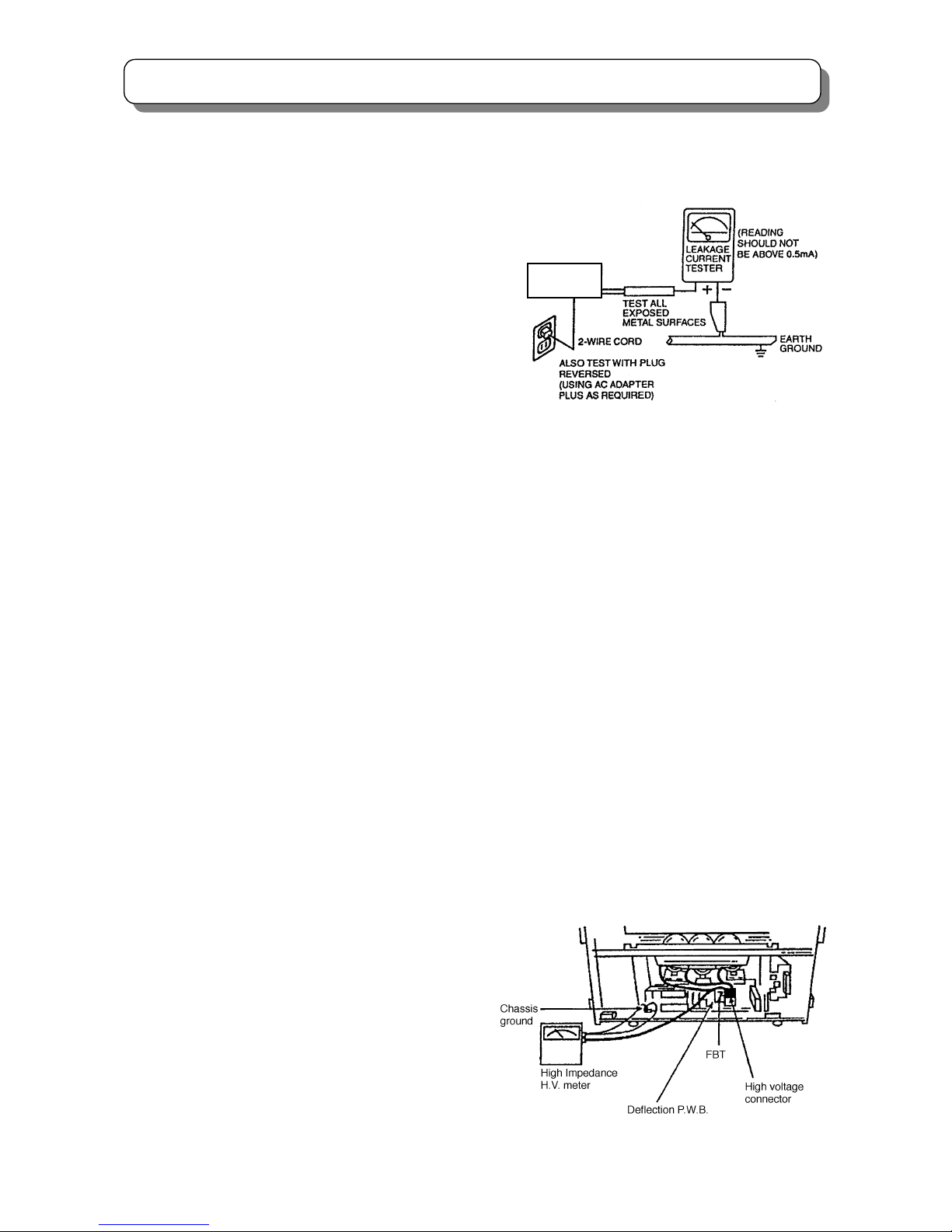
d) Leakage Current Hot Check - With the instrument
completely reassembled, plug the AC line cord
directly into a 220V outlet. (Do not use an isolation
transformer during this test.) Use a leakage current
tester or a metering system with the instrument AC
switch first in the ON position and then in the OFF
position, measure from a known earth ground (metal
water-pipe, conduit, etc.), to all exposed metal parts
of the instrument (antennas, handle bracket, metal
cabinet, screw heads, metallic overlays, control
shafts, etc.), especially any exposed metal parts that
offer an electrical return path to the chassis. Any
current measured must not exceed 0.7 milliamps.
Reverse the instrument power cord plug in the outlet
and repeat test. (See the following connection
diagram)
AC Leakage Test
ANY MEASUREMENTS NOT WITHIN THE LIMITS
SPECIFIED HEREIN INDICATE A POTENTIAL
SHOCK HAZARD THAT MUST BE ELIMINATED
BEFORE RETURNING THE INSTRUMENT TO THE
CUSTOMER OR BEFORE CONNECTING THE
ANTENNA OR ACCESSORIES
e) High Voltage - This receiver is provided with a hold
down clearly indicating that voltage has increased in
excess of a predetermined value. Comply with all
notes described in this Service Manual regarding
this hold down circuit when servicing, so that this
hold down circuit may correctly be operated.
f) Service Warning - With maximum contrast,
operating high voltage in this receiver is lower than
31.0kV. In case if any component having influence
on high voltage is replaced, confirm that the high
voltage with maximum contrast is lower than 31.6kV.
To measure H.V use a high impedance H.V. meter.
Connect (-) to chassis earth and (+) to the CRT
anode button. (See the following connection
diagram).
Note: Must turn power switch off before the connection
to the anode button is made.
(TH01)
INSTRUMENT
UNDER TEST
Page 4
4
SAFETY PRECAUTIONS
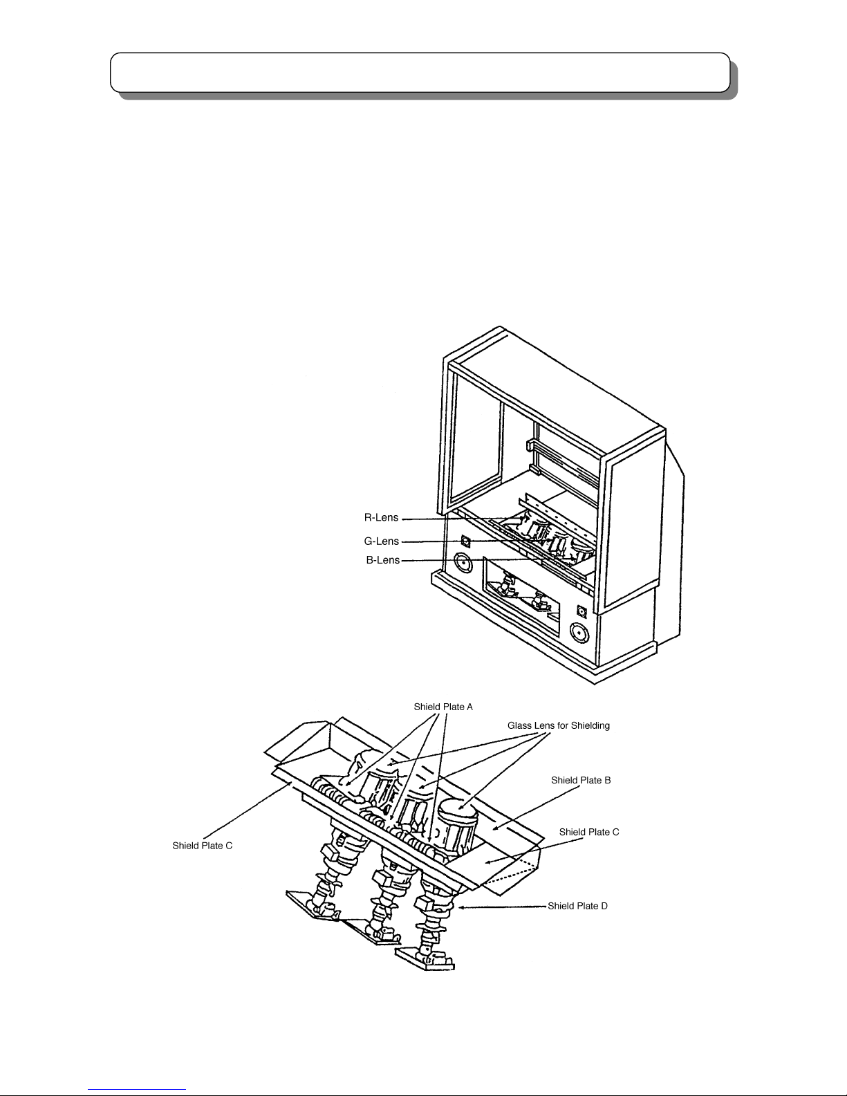
Fig. 1 X-ray shield plates
g) X-radiation (TUBE) -The primary source of
X-radiation in this receiver is the picture tube. The tube
utilized for the above mentioned function in this
chassis is specially constructed to limit X-radiation
emissions.
For continued X-radiation protection, the replacement
tube must be the same type as the original. HITACHI
approved type.
When troubleshooting and making test measurements
in a receiver with a problem of excessive high voltage,
avoid being unnecessarily close to the picture tube
and the high voltage component.
Do not operate the chassis longer than is necessary
to locate the cause of excessive voltage.
h) X-radiation Shield -This receiver is provided with
X-ray shield plates for protection against X-radiation.
Do not remove X-ray shield plates A, B, C, or D
shown in Fig.1 unnecessarily, when troubleshooting
and/or making test measurements.
To prevent X-radiation, after replacement of picture
tube and lens, confirm these components to be fixed
correctly to bracket and cabinet, and not to be taken
off easily.
Page 5

5
SAFETY PRECAUTIONS
2. Read and comply with all caution and safety-related
notes on or inside the receiver cabinet, on the
receiver chassis, or on the picture tube.
3. Design Alteration Warning - Do not alter or add to
the mechanical or electrical design of this TV receiver.
Design alterations and additions, including but not
limited to circuit modifications and the addition of
items such as auxiliary audio and/or video output
connectors, might alter the safety characteristics of
this receiver and create a hazard to the user. Any
design alterations or additions may void the
manufacturer’s warranty and may make you, the
servicer, responsible for personal injury or property
damage resulting therefrom.
4. Picture Tube Implosion Protection Warning - The
picture tube in this receiver employs integral
implosion protection. For continued implosion
protection, replace the picture tube only with one of
the same type number. Do not remove, install, or
otherwise handle the picture tube in any manner
without first putting on shatterproof goggles equipped
with side shields. People not so equipped must be
kept safely away while picture tubes are handled.
Keep the picture tube away from your body. Do not
handle the picture tube by its neck.
5. Hot Chassis Warning
a) Some TV receiver chassis are electrically connected
directly to one conductor of the AC power cord and
may be safely serviced without an isolation
transformer only if the AC power plug is inserted so
that the chassis is connected to the ground side of the
AC power source. Confirm that the AC power plug is
inserted correctly with an AC voltmeter by measuring
between the chassis and a known earth ground. If a
voltage reading in excess of 1.0V is obtained, remove
and reinsert the AC power plug in the opposite polarity
and again measure the voltage potential between the
chassis and a known earth ground.
b) Some TV receiver chassis normally have 85V AC
(RMS) between chassis and earth ground regardless
of the AC plug polarity. These chassis can be safely
serviced only with an isolation transformer inserted in
the power line between the receiver and the AC power
source, for both personnel and test equipment
protection.
c) Some TV receiver chassis have a secondary ground
system in addition to the main chassis ground. This
secondary ground system is not isolated from the AC
power line. The two ground systems are electrically
separated by insulating material that must not be
defeated or altered.
6. Observe original lead dress. Take extra care to assure
correct lead dress (the AC supply, high voltage and
antenna wiring) in the following areas:
a) Near sharp edges
b) Near thermally hot parts
Be sure that leads and components do not touch
thermally hot parts. Always inspect in all areas for
pinched, out-of -plate, or frayed wiring; Do not
change spacing between components and the printed
circuit board; Check AC power cord for damage.
7. Components, parts, and/or wiring that appear to have
overheated or are otherwise damaged should be
replaced with components, parts or wiring that meet
original specifications. Additionally, determine the
cause of overheating and/or damage and, if
necessary, take corrective action to remove any
potential safety hazard.
8. PRODUCT SAFETY NOTICE - Many TV electrical
and mechanical parts have special safety-related
characteristics some of which are often not evident
from visual inspection, nor can the protection they
give necessarily be obtained by replacing them with
components rated for higher voltage, wattage, etc.
Parts that have special safety characteristics are
identified by a
! in the replacement parts list. Use of
substitute replacement that does not have the same
safety characteristics as the recommended
replacement part in the parts list might create shock,
fire, and/or other hazards. Product safety is under
review continuously and new instructions are issued
whenever appropriate. For the latest information,
always consult the appropriate current service
literature. A subscription to, or additional copies of
service literature may be obtained at a nominal
charge from manufacturer.
Page 6

6
TECHNICAL CAUTIONS
High Voltage limiter circuit operation check
1. Turn off TV and delete Resistor RH19(82KΩ)in the PWB .Add jig A to the RH19 position in the PWB,set 50 KΩ
VR fully clockwise(maximum resistance).
2. Set the AC input to 242V AC and turn on TV.
3. Confirm test pattern on PRT is a usable picture,then slowly adjust 50 KΩVR until the picture disappears and TV
shuts down.
4. When the limiter circuit is operating properly, High Voltage will be less than 36.8KV at 1.6mA when TV shuts down.
5. Turn off TV immediately after checking High Voltage limiter circuit operation. Unplug TV for one minute to reset
shutdown circuit. Remove the jig A,and the
n add resistor RH19(82KΩ)to the P.W.B.
Fig.2 High Voltage limiter circuit operation check
FBT
TH01
Jig A
50 KΩ VR
33KΩ
Connect Jig A to P.W.B between RH19.
Deflection/Convergence P.W.B
FBT
RH19
50 KΩ VR
33KΩ
RH17
Page 7
7
7
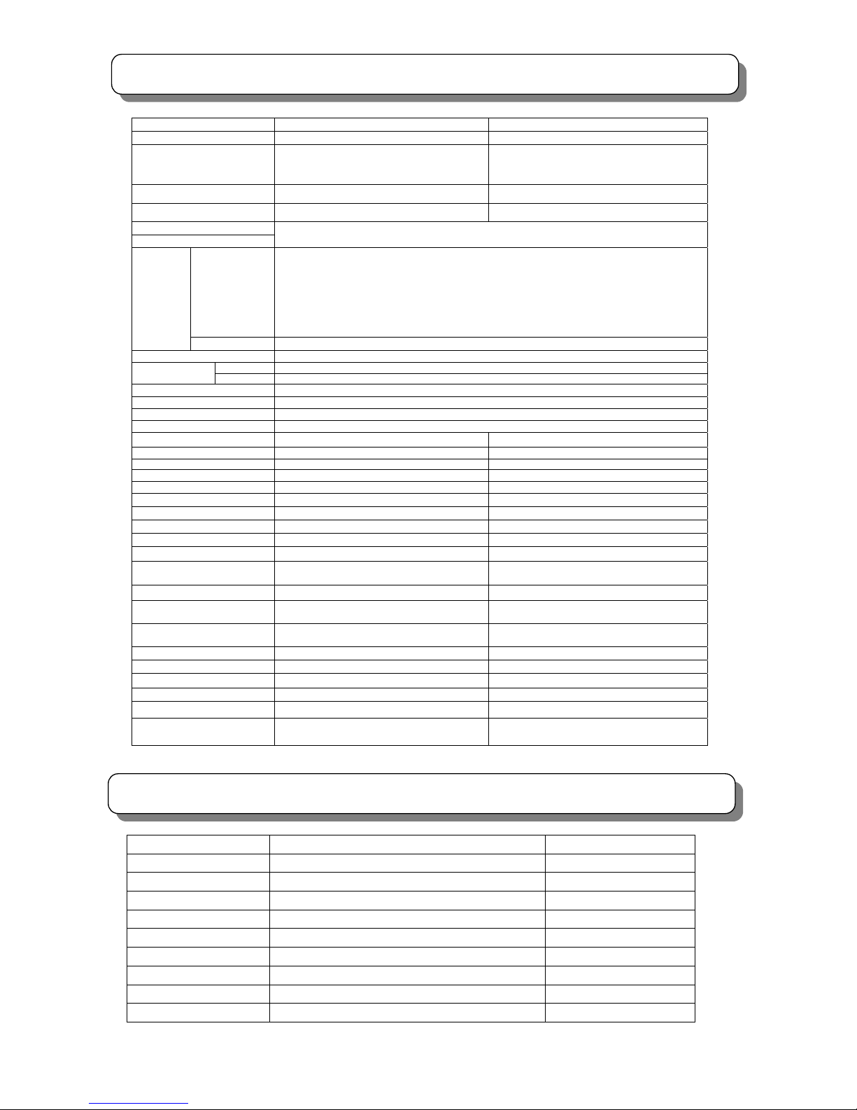
SPECIFICATIONS
CIRCUIT PROTECTION
Fuse (or Device) Circuit Protected Physical Location
F9C1 (T6.3AL/250V) Main Primary Fuse Power PWB
F903 (T3.15AL/250V) Primary Fuse Power PWB
E901 7A Fuse Protector Over Current Protector (Audio +38.5V Power Supply) Power PWB
E902 7A Fuse Protector Over Current Protector (SW +10V Power Supply) Power PWB
E903 4A Fuse Protector Over Current Protector (SW +220V Power Supply) Power PWB
E904 10 A Fuse Protector Over Current Protector (SW +28V Power Supply) Power PWB
E905 10A Fuse Protector Over Current Protector (SW -28V Power Supply) Power PWB
E906 0.5A Fuse Protector Over Current Protector (+B Error AMP) Power PWB
E907 3A Fuse Protector Over Current Protector (+B Power Supply) Power PWB
Model
C43-FD5000 C50-FD5000
Screen size
109cm 127cm
Cathode Ray Tube
R: P16LXL00RFA(C)
G: P16LXL00HHA(C)
B: P16LXL00BMB(C)
R: P16LXL00RFA(C)
G: P16LXL00HHA(C)
B: P16LXL00BMB(C)
Lens HSA SCB
Anode voltage 30.7KV 30.7KV
Power supply
Power consumption
Refer to the values as indicated on the rating label pasted at the back of the TV set.
PAL B.G/I/D.K
SECAM B.G/D.K
NTSC 50
M/NTSC
NTSC3.58-5.5/6.0/6.5
NTSC4.43-5.5/6.0/6.5
RF/VIDEO
PAL/SECAM 60
Reception
system
COMPONENT 525i/525p/625i/625p/750p/1125i
Frequency range 44MHz-863 MHz
VHF Not less than 250uVReception
sens
itivity
U
HF Not l
ess
than
350u
V
Antenna input impedance 75 Ohm non balance type
Speaker
Φ12×2 、Φ5×2
Sound output
20 W×2
Comb filter 3L(PAL)/3D(NTSC)
Digital convergence Yes Yes
Magic focus Yes Yes
Perfect volume Yes Yes
NICAM/A2 Yes Yes
BBE Yes Yes
SRS Yes Yes
P i n P Yes Yes
Tel e t ext Ye s Yes
S-VIDEO input
1 ( side),2(back
)1(
side),2 (back)
VIDEO input 1 (side),4(back) 1 (side),4(back)
Component input
(Y, PB/CB, PR/CR)
2 (back) 2 (back)
AUDIO (L, R) input 1 (side),4(back) 1 (side),4(back)
VIDEO output
(
MONITOR OUT)
1(back) 1(back)
AUDIO(L,R)output
(MONITOR OUT)
1(back) 1(back)
Headphone output jack 2 (side) 2 (side)
Variable audio (L、R) output
1(back) 1(back)
Shielding Yes Yes
Memory card slot No No
Weight 55Kg 62.5Kg
Dimension (mm)
(width×depth×height)
969 ㎜×534 ㎜×1237 ㎜ 111 9 ㎜×535 ㎜×1362 ㎜
Page 8
8
GENERAL INFORMATION
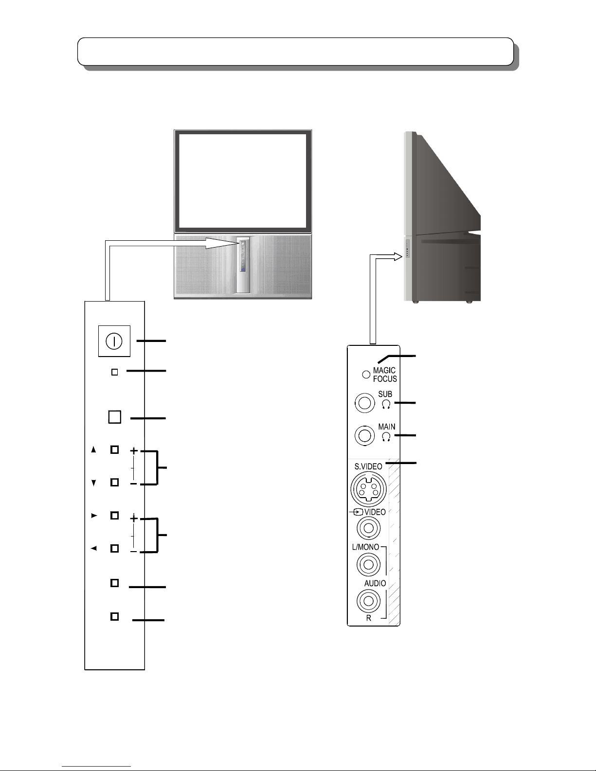
Control panel and side panel
POWER
PROGRAM
VOLUME
TV/VIDEO
MENU/RETURN
Power ON/OFF switch
Power/ standby indicator
Remote control sensor
PROGRAM UP/DOWN buttons (When
the menu appears on the screen, press
PROGRAM UP/DOWN buttons to
select the menu up and down.)
VOLUME UP/DOWN buttons (When the
menu appears on the screen, press
VOLUME UP/DOWN buttons to select
the menu right and left.)
MENU/RETURN button
TV/VIDEO selector
POWER
5
I
P
T
U
N
Main headphone jack
Sub headphone jack
Magic focus button
Side panel input jacks
(For AV5 input)
Page 9
9
GENERAL INFORMATION
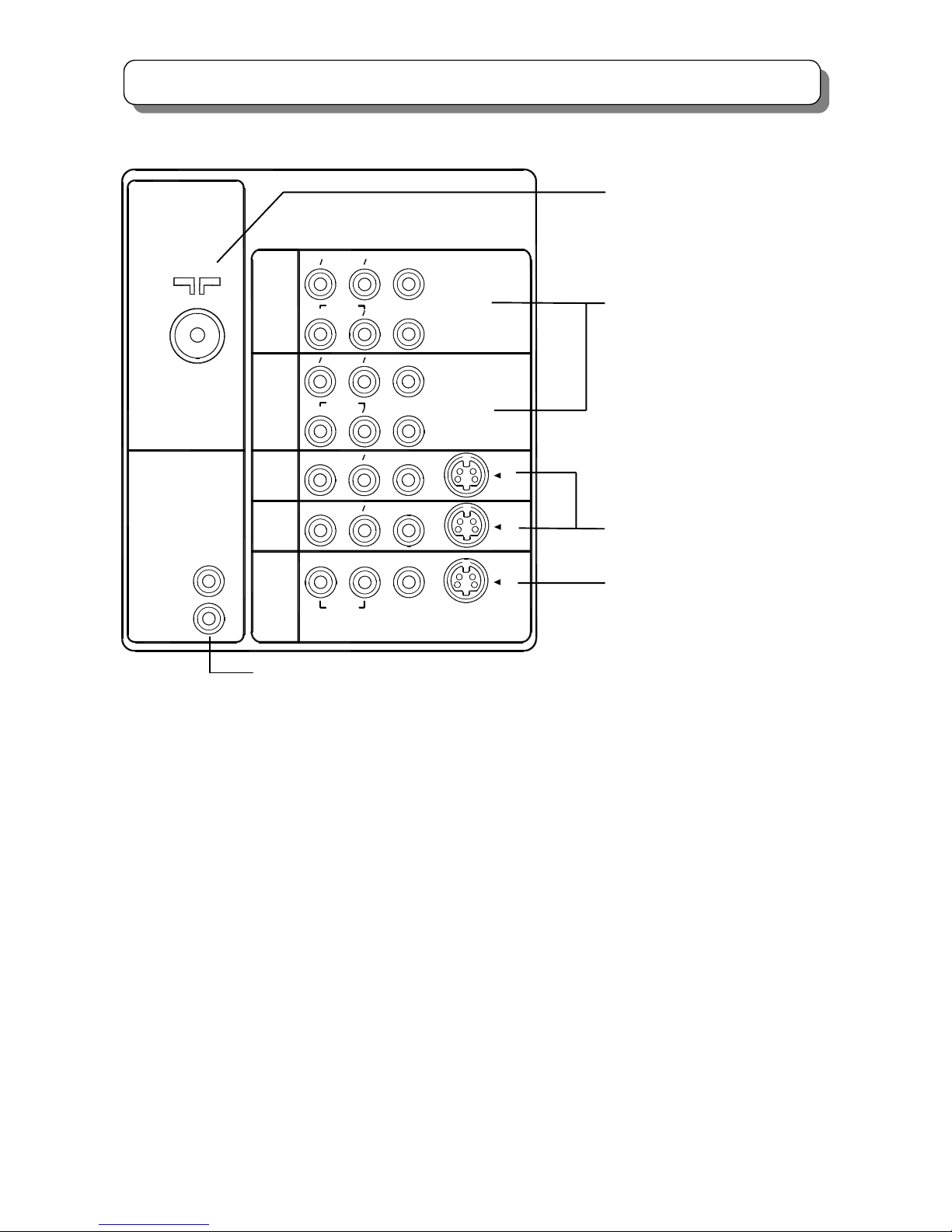
REAR PANEL
AUDIO OUT
MONITOR
R
L
OUT
AUDIO
R
LVIDEO
S-VIDEO
VARIABLE
R
(MONO)
L
INPUT 4
INPUT 3
R
L
(MONO)
INPUT 2
L
R
AUDIO
(MONO)
VIDEO S-VIDEO
VIDEO
S-VIDEO
VIDEO
B
C
INPUT 1
P
C
RR
BP
C
AUDIO
R
(MONO)
L
C
P
RR
PB
Y
VIDEO
Y
B
Variable Audio output terminals
A
ntenna terminal
Monitor output terminals
A
udio/Video input & Component
in
p
ut terminals 1,2
A
udio/Video input terminals 3,4
Page 10
10
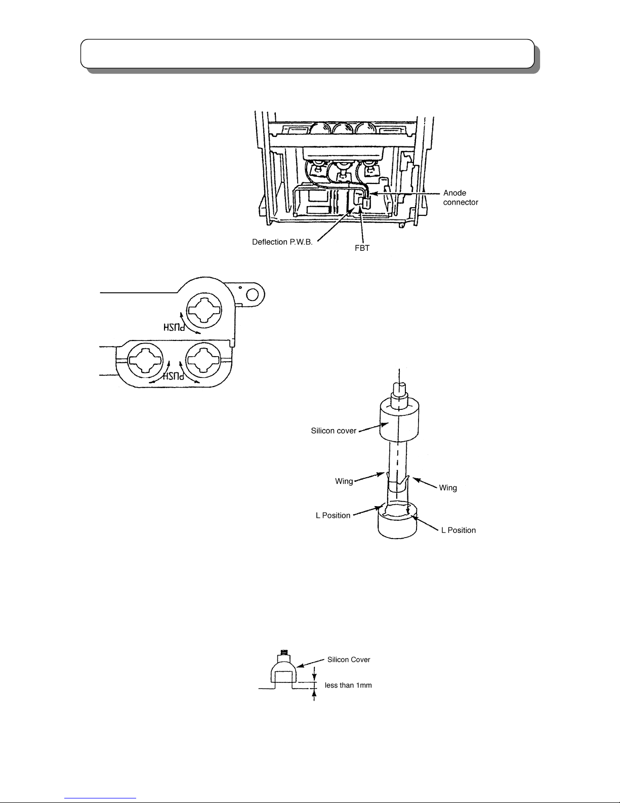
CAUTIONS WHEN CONNECTING/DISCONNECTING THE HV CONNECTOR
O
O
L L
L
Perform the following when the
HV connector (anode connector)
is removed or inserted for PRT
replacement, etc.
During Insertion
1. Please refer to direction for insertion as shown in Fig. 4 (L position). Insert connector until “CLICK” sound is heard.
2. Make sure the connector is pressed right in, so that it has a good contact with the spring.
3. Confirm the contact by pulling the connector slightly. (Don’t pull hard because it may damage the connector).
4. Cover the high voltage output by carefully pushing silicon cover onto it. (Don’t turn the connector).
(REMARK)
1. Make sure the silicon cover is
covering the high voltage output.
During Removal
1. Roll out silicon cover from FBT’s contact area slowly.
2. While turning the connector about 90 degrees following the
arrow (from L position to O position), push the connecto
r
slightly towards the case. (Fig .3)
3. Remove the connector slowly by pulling it away from the
case.
Fig. 3 Remove the anode connector
Fig. 4 Insert the anode connector
Page 11

11
SERVICE ADJUSTMENTS
SERVICE ADJUSTMENT ITEMS
1.ASSEMBLED P.W.B ADJUSTMENT……………………………………………………… (12)
1.1 MEMORY INITIALIZE…………………………………………………………………… (12)
1.2 MAIN AGC ADJUSTMENT………………………………………………………………
(12)
1.3 SUB AGC ADJUSTMENT………………………………………………………………..(13)
2.FINAL ASSEMBLY ADJUSTMENT…………………………………………………………(13)
2.1 CUT OFF ADJUSTMENT……………………………………………………………….. (13)
2.2 RASTER TILT ADJUSTMENT…………………………………………………………..(14)
2.3 DCU PHASE DATA SETTING………………………………………………………….. (14)
2.4 BEAM ALIGNMENT…………………………..…………………………………………..(15)
2.5 RASTER POSITION ADJUSTMENT………..………………………………………….(16)
2.6 SIDE PIN DISTORTION ADJUSTMENT………..……………………………………...(17)
2.7 VERTICAL SIZE ADJUSTMENT………..………………………………………………(18)
2.8 HORIZONTAL SIZE ADJUSTMENT………..…………………………………………. (19)
2.9 TRAPEZOID DISTORTION ADJUSTMENT………..………………………………….
(20)
2.10 BEAM FORM ADJUSTMENT………..………………………………………………...(21)
2.11 LENS FOCUS ADJUSTMENT………..………………………………………………..(21)
2.12 STATIC FOCUS ADJUSTMENT………..……………………………………………..(24)
2.13 DYNAMIC FOCUS CHECK………..…………………………………………………..
(24)
2.14 DIGITAL CONVERGENCE ADJUSTMENT………..………………………………...(25)
2.15 SCANNING AREA CHECK………..…………….…………………………………... ..(34)
2.16 BLUE DEFOCUS ADJUSTMENT………..…………………………………………... (36)
2.17 WHITE BALANCE ADJUSTMENT………..………………………………………..... (36)
2.17.1 CHECK CUT OFF ADJUSTMENT………..……………………………….…..
(36)
2.17.2 WHITE BALANCE ADJUSTMENT………..…………………………………...(36)
2.18 SUB BRIGHTNESS ADJUSTMENT………..………………………………………...
(38)
2.19 SUB PICTURE WHITE BALANCE ADJUSTMENT………..………………………..
(39)
2.20 TINT ADJUSTMENT………..………………………………..……………………….. .(39)
2.21 MAGIC FOCUS INITIALIZE………..…………………………………..………….…..
(40)
2.21.1 MAGIC FOCUS INITIALIZE………..……………………………………….…. (40)
2.21.2 CONVERGENCE ERRORS………..…………………….…………….……... (41)
3. ADJUSTMENT POINT………..…………………………………..………………………....
(42)
3.1 PRT CABINET LOCATIONS…………..…..………………………………………..…..
(42)
3.2 FOCUS PACK………..……………………………………………………………….…..
(42)
3.3 MAIN P.W.B. ………..…………………………………….………………………….…..
(43)
4. SERVICE MENU………..……………………………………………………….…………....(49)
4.1 ADJUSTMENT PROCEDURE………..…………………………………………….….. (49)
4.2 SERVICE MENU………..…………………………………………………………….…..(49)
Page 12
12
SERVICE ADJUSTMENTS
● Before performing SERVICE ADJUSTMENTS, please refer to the item “TROUBLE SHOOTING”.
1. ASSEMBLED P.W.B ADJUSTMENT
1.1 MEMORY INITIALIZE
Adjustment Procedure by R/C Jig.
(1) Select item No.612 (set2) in service menu, press and hold the [RECALL] key on the remote handset until the
OSD background changes to yellow. (It takes about 3 seconds.)
(2) Wait until the OSD background color becomes normal, this means initialize is completed and each settings
become factory preset condition.
Do not unplug the outlet or perform any key operation until the initialize is completed.
Note: Other method for memory initialize: Link the PRST① and PRST② for longer than 3 seconds.
(3) Change initial-setting values according to the INITIAL-SETTING CHANGE TABLE.
(4) After set the above items in service menu, set to SHIPMENT by following method.
Select
item (set1) in service menu, press the [ENTER] key or [MUTE] key on the remote handset.
(5)
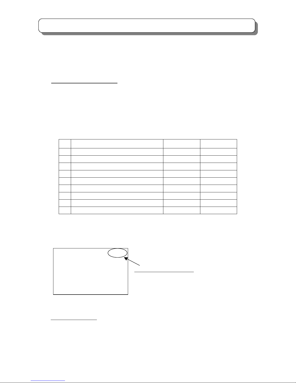
Check the setting state displayed on the upper right of a service menu.
1.2 MAIN AGC ADJUSTMENT
Adjustment Preparation
(1) To prevent circuit temperature drift, the set must apply heat run for more then 10 minutes.
(2) Check the RF signal frequency and level accuracy. (e.g. 623.25MHz, -50dBm)
(3) Confirm the function of antenna attenuation is set to OFF.
N
o. Data V203-007-898C-000112100
Color:PAL Sound:6.5
0: 0
1: 1
2: 0
3: 0
The state of Model Select setting
From the left to the 1st figure:The state of Model Select1
…
From the left to the 9th figure:The state of Model Select9
Items
C43-FD5000 C50-FD5000
1
Model Select1:ASPECT
0 0
2
Model Select2:HD
0 0
3
Model Select3:MULTI_PICTURE
0 0
4
Model Select4:DESTINATION
1 1
5
Model Select5:LANGUAGE
1 1
6
Model Select6:SOUND_SYS/COLOR_SYS
2 2
7
Model Select7:TEXT
1 1
8
Model Select8:PHOTO_MC
0 0
9
Model Select9:LIGHT
0 0
Page 13
13
SERVICE ADJUSTMENTS
Adjustment Procedure
(1) Receive ch27 China or ch40 CCIR. (623.25MHz, -50dBm) in service mode.
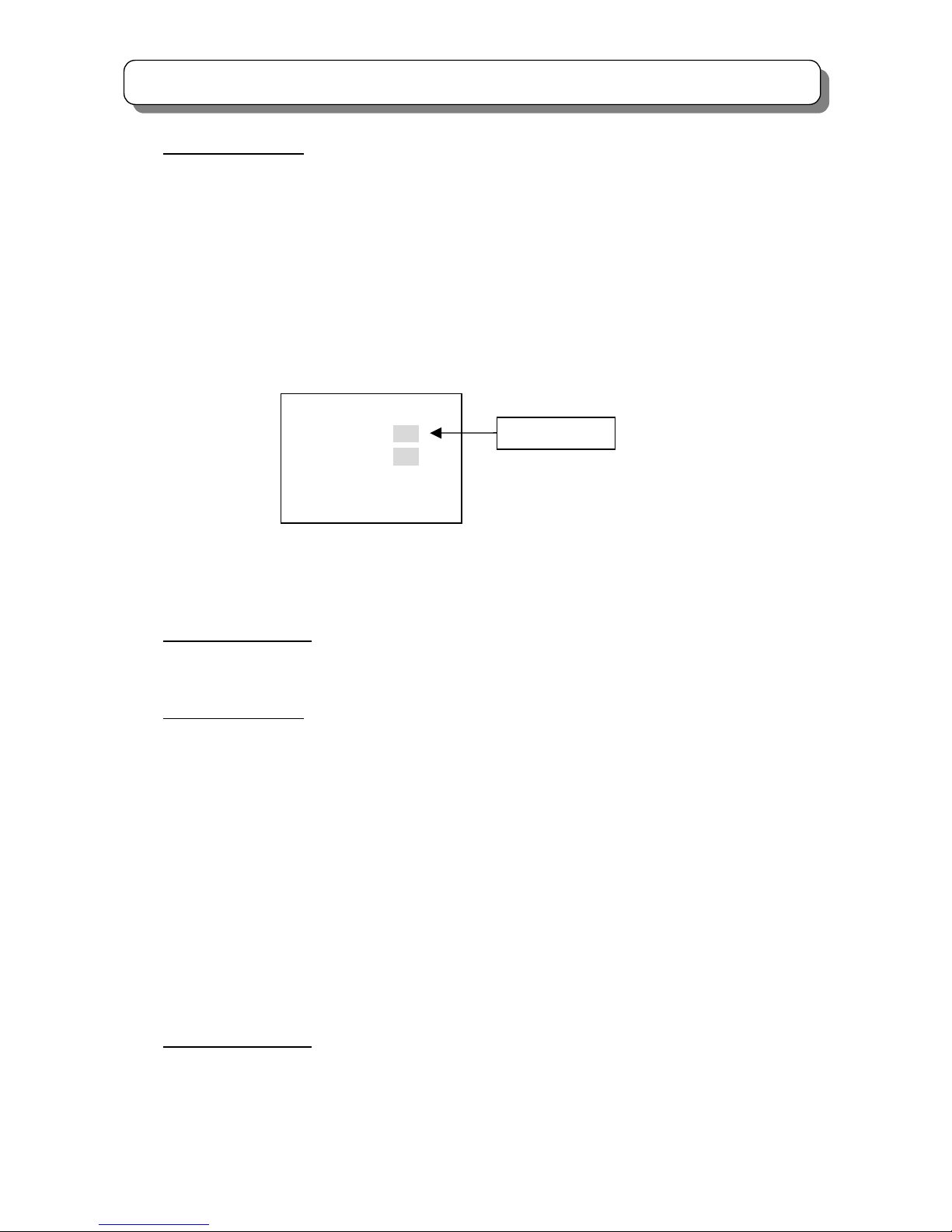
(2) Select item No.11 in service menu by [▲] or [▼] key.
(3-1) When the value of AGC (NO.11 in service menu) is 235 or less than 235.
(3-1-1) Push [►] key of remote control and set AGC value becomes 235 or greater than 235.
(3-1-2) Push the "MUTE" button of remote control, and then AGC adjustment is completed.
(3-2) When the value of AGC (NO.11 in service menu) is 235 or greater than 235.
(3-2-1) Set the value of AGC by [◄] key of remote control to smaller than 235.
(3-2-2) Then push [►] key of remote control and set the AGC value again to greater than and as close as 235.
(3-2-3) Push the "MUTE" button of remote control, and then AGC adjustment is completed.
1.3 SUB AGC ADJUSTMENT
Adjustment Preparation
(1) To prevent circuit temperature drift, the set must be warmed up before alignment longer than 10 minutes.
(2) Check the RF signal frequency and level accuracy. (e.g. 623.25MHz, -50dBm)
Adjustment Procedure
(1) Press [PIP] button to display sub picture, and receive the signal, ch27 China or ch40 CCIR (623.25MHz,
-50dBm) in adjustment mode.
(2) Select item No.12 in service menu by [▲] or [▼] key.
(3-1) When the value of AGC (NO.12 in service menu) is 235 or less than 235.
(3-1-1) Push [►] key of remote control and set AGC value becomes 235 or greater than 235.
(3-1-2) Push the "MUTE" button of remote control, and then AGC adjustment is completed.
(3-2) When the value of AGC (NO.12 in service menu) is 235 or greater than 235.
(3-2-1) Set the value of AGC by [◄] key of remote control to smaller than 235.
(3-2-2) Then push [►] key of remote control and set the AGC value again to greater than and as close as 235.
(3-2-3) Push the "MUTE" button of remote control, and then SUB AGC adjustment is completed.
2. FINAL ASSEMBLY ADJUSTMENT
2.1 CUT OFF ADJUSTMENT
Adjustment Preparation
(1) Pre-set (turn counterclockwise to the end) the screen VR (R, G and B) on FOCUS PACK. Then pre-heat the
set.
(2) Confirm item No. 47、48 and 49 are set to 127 in service menu.
No. V0XX
11 34 235
12 54 234
13 64
14 32
Value of AGC
Page 14
14
SERVICE ADJUSTMENTS
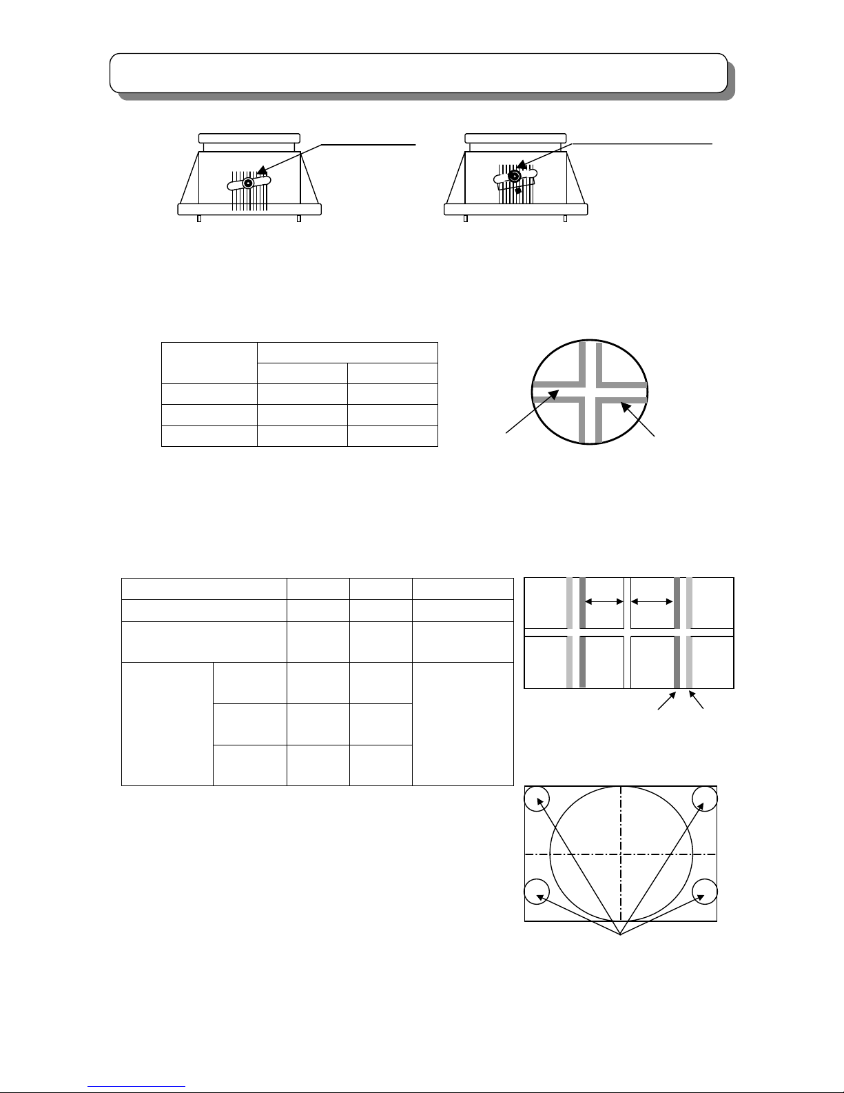
L
L
1
Adjustment Procedure
(1) Enter “SERVICE MENU” and select item No.10. Press [►] key to enter CUT OFF adjustment mode.
(2) Turn screen VR (R, G and B) clockwise gradually until each horizontal line (R, G or B) begins to appear.
(3) Press [◄] key to return normal mode.
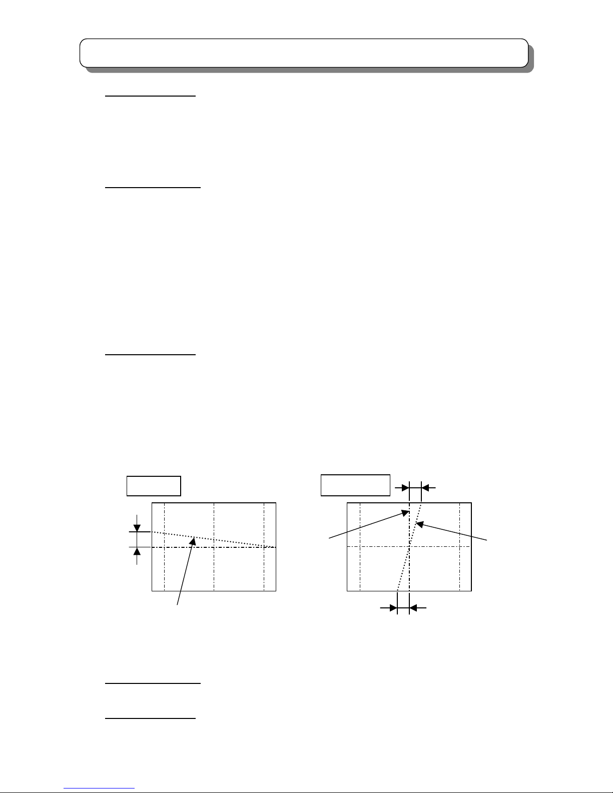
2.2 RASTER TILT ADJUSTMENT
Adjustment Preparation
(1) Face the set East or West.
(2) Receive the NTSC cross-hatch signal.
(3) Contrast should be set maximum and the other controls should be set center.
(4) The lens focus should be coarsely adjusted.
(5) The electrical focus should be coarsely adjusted.
(6) The digital convergence should not be corrected.
(7) Turn the Main power switch off.
(8) Press and hold the “SERVICE ONLY” switch on CONVERGENCE/FOCUS P.W.B. and switch on the Main
power.
Adjustment Procedure
(1) Apply covers to the R and B lenses or short the TS (2P SUB MINI Connector) on R and B on CPT P.W.B. to
project only green beam.
(2) Turn the G deflection yoke and adjust the Vertical raster inclination. (Fig. 5)
(3) Remove the cover of R or B lens and display blue light and green light together on the screen.
(4) Turn the deflection yoke of R or B and adjust the inclination of R or B light with reference to the green light as
shown on Fig. 6.
(5) After the adjustment, fix the screw of each DY with a torque of 1.18 Nm (12kgfcm).
2.3 DCU PHASE DATA SETTING
Adjustment Preparation
(1) Complete cut off adjustment.
Adjustment Procedure
(1) Receive any PAL signal and Set to 100HZ mode. (RF or VIDEO)
L2
L1, L2≦±2mm
R or B
G
L≦±2mm
Vertical center axis of cross-hatch signal
Fig. 5 Raster inclination (G)
Fig. 6 Raster inclination (R or B)
Page 15
15
SERVICE ADJUSTMENTS
(2) Contrast should be set center and the other controls should be set standard.
(3) Push the “SERVICE ONLY” switch on the CONVERGENCE P.W.B. to set the digital convergence unit to the
adjustment mode.
(4) Phase set
1) Press the [ REVEAL] key on R/C to display the green cross-hatch pattern.
2) Press the [ CHⅠ /Ⅱ ] key to recall the phase DATA on screen.
PAL 100i mode PAL 50p mode NTSC 60p mode
3) If phase data is not same as above, change the DATA by using the following R/C keys.
Press [4] or [6] key to adjust the PH-H
Press [2] or [5] key to adjust the PH-V
Press [◄] or [►] key to adjust the CR-H
Press [▲] or [▼] key to adjust the CR-V
4) Press the [REVEAL] key to exit from phase mode.
5) Press [INDEX] key on R/C twice to write the data into ROM.
6) Push the “SERVICE ONLY” switch on the CONVER P.W.B. twice to exit from adjustment mode of the
digital convergence unit.
(4) Change to PAL50p mode (Set DCU the PAL50p mode) and repeat procedure (2)-(3) for PAL50p mode.
(5) Change to NTSC mode (Set DCU to the NTSC mode) and repeat procedure (2)-(3) for NTSC mode.
2.4 BEAM ALIGNMENT
Preparation for adjustment
(1) Pre-heat 30 minutes or more before the adjustment.
(2) The static convergence data should be cleared.
(3) Raster inclination should be adjusted. Optical focus should be coarsely adjusted.
(4) Contrast should be set MAX and the other control should be set Center.
(5) Receive the NTSC cross-hatch pattern signal or Dot pattern signal.
(6) Discharge static charge from metallic parts on PRT NECK by using Short-clip-JIG.
Adjustment procedure
(1) Green (G) tube alignment: Short-circuit 2P sub-mini connectors on the red ( R ) and blue (B) CPT P.W.B.s and
project the only green beam.
(2) Set the G tube beam alignment magnet to the cancel state as shown on right.
PHASE MODE: 1
PH-H: E7
PH-V: 0C
CR-H: 35
CR-V: 1C
PHASE MODE: 6
PH-H: DD
PH-V: 07
CR-H: 33
CR-
V
: 14
PHASE MODE: 5
PH-H: E7
PH-V: 16
CR-H: 35
CR-
V
: 1C
Page 16
16
SERVICE ADJUSTMENTS
(3) Turn the static focus VR*
1
for Green fully counterclockwise and check the cross-hatch center position on the
screen.
Note : Halo state
(4) Turn the static focus VR*
1
for Green fully clockwise.
(5) Turn 2 sheets of the alignment magnet in either direction and move the cross-hatch center to the position
where is checked in step (3).
(6) Turn the static focus VR*
1
for Green and check if the picture position moves or not.
(7) Repeat steps (2) to (6) until the picture position does not move during step (6)
(8) In the same manner, adjust the Red ( VR )*
2
and the Blue (VR)*3 tube alignments.
(9) Fix the beam alignment magnet with white paint after the alignment is completed.
VR*
1
VR*
2
Static Focus VR is on focus pack UFPK
VR*3
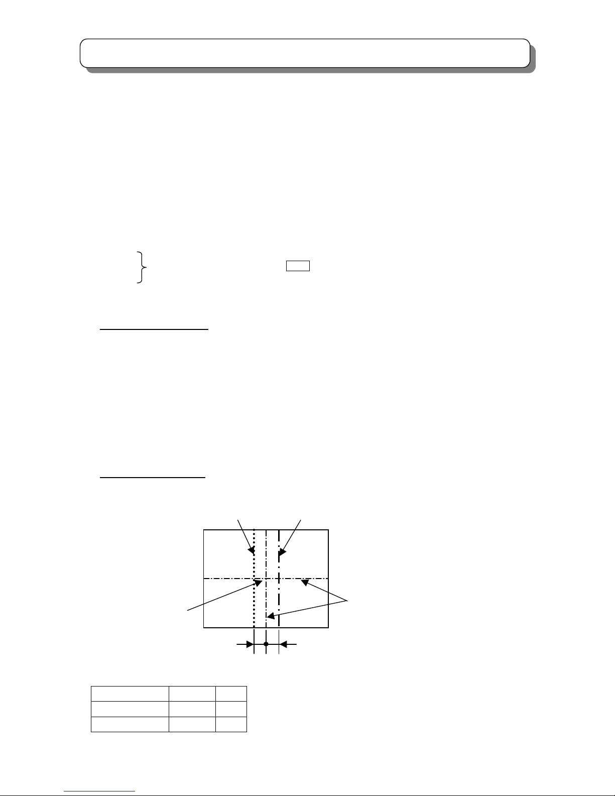
2.5 RASTER POSITION ADJUSTMENT
Preparation for adjustment
(1) Place the set facing east or west.
(2) Receive the NTSC Hitachi circle pattern signal. (Set the NTSC mode)
(3) Contrast control should be set Maximum and the other controls should be set Center.
(4) The raster inclination and beam alignment should be adjusted.
The lens focus and electric focus adjustment should be coarsely adjusted.
(5) The convergence should be uncorrected state.
(6) Turn the Main power SW off.
(7) Press and hold the “SERVICE ONLY” SW. on CONV./FOCUS P.W.B. and switch on the Main power.
(8) Press “SERVICE ONLY” SW again to display the DCU’s cross-hatch pattern.
Adjustment procedure
(1) Turn the centering magnets for R, G and B to get the center point of the cross-hatch position
within specification as shown below.
R B
Geometric center of the screen
G
[Horizontal direction] Unit:mm
R: L
1
to the left from the geometric center of the screen,L1±2mm
B: L
2
to the right from the geometric center of the screen,L2±2mm
G: To geometric center of screen.
4:3 L1 L
2
43” 20 30
50” 20 30
L
2
L1
Page 17
17
SERVICE ADJUSTMENTS
[Vertical direction]
Both of the distance between the central horizontal line of R, B and the geometric center of the screen should be
within ±2mm.
(2) After the adjustment is completed, fix the R, G and B centering magnets using white paint.
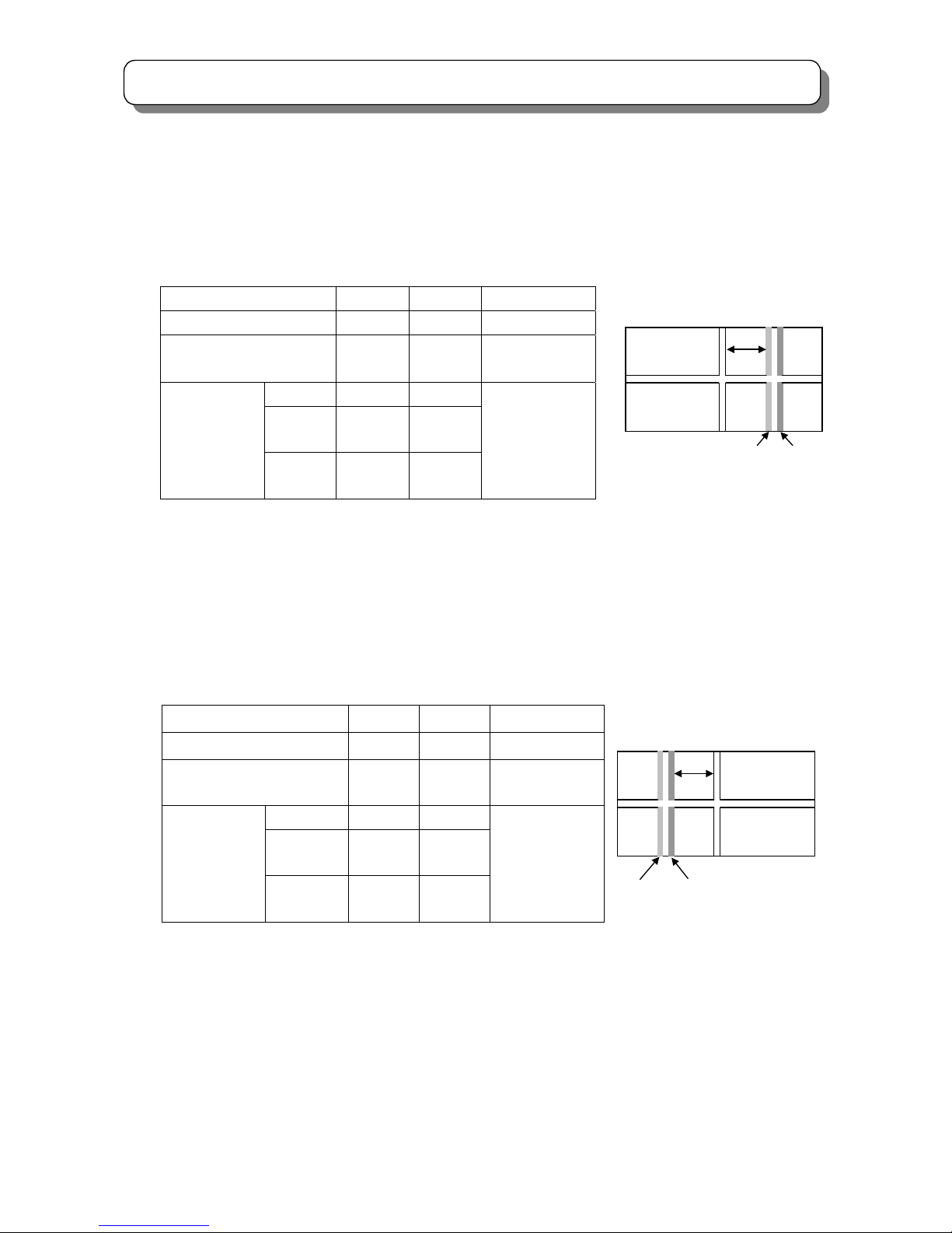
2.6 SIDE PIN DISTORTION ADJUSTMENT
Adjustment Preparation
(1) VIDEO control should be set to Factory Preset condition.
(2) Place the set facing east.
(3) DCU ROM CHECK should be completed.
Adjustment Procedure
PAL 100i MODE I2C No.15
(1) Input any PAL signal.
(2) Press [MENU] key.
(3) Choose FUNCTION and SCAN, and set to 100Hz mode.
(4) Press [MENU] key twice to exit from FUNCTION.
(5) Press and hold the SERVICE ONLY SW. on CONV./FOCUS P.W.B. and press [MUTE] key of Hands
-et. Green DCU cross-hatch are appeared with Conv. Data cleared.
(6) Press the [TV/VIDEO] button on the control panel, then SERVICE MENU appears.
(7) Choose SIDE PIN (EW parabola) item by using Handset up/down cursor key.
(8) Adjust SIDE PIN as following by using Handset left/right cursor key.
(9) Press [MUTE] key of handset to write the adjusted data.
(10) After adjustment, press SERVICE ONLY SW. to exit from SERVICE mode.
PAL 50Hz PROGRESSIVE MODE I
2
C No.19
(1) Input any PAL signal.
(2) Press [MENU] key.
(3) Choose FUNCTION and SCAN, and set to Progressive mode.
(4) Press [MENU] key to exit from FUNCTION.
(5) Adjust the same items as (5)-(10) of setting PAL 100i MODE.
NTSC 60Hz PROGRESSIVE MODE I
2
C No.23
(1) Input any NTSC signal.
(2) Adjust the same items as (5)-(10) of setting PAL 100i MODE.
Edge of vertical DCU cross-hatch line
should be straight condition.
Note: If it’s impossible to adjust the
straight line, set a little pin condition.
Page 18
18
SERVICE ADJUSTMENTS
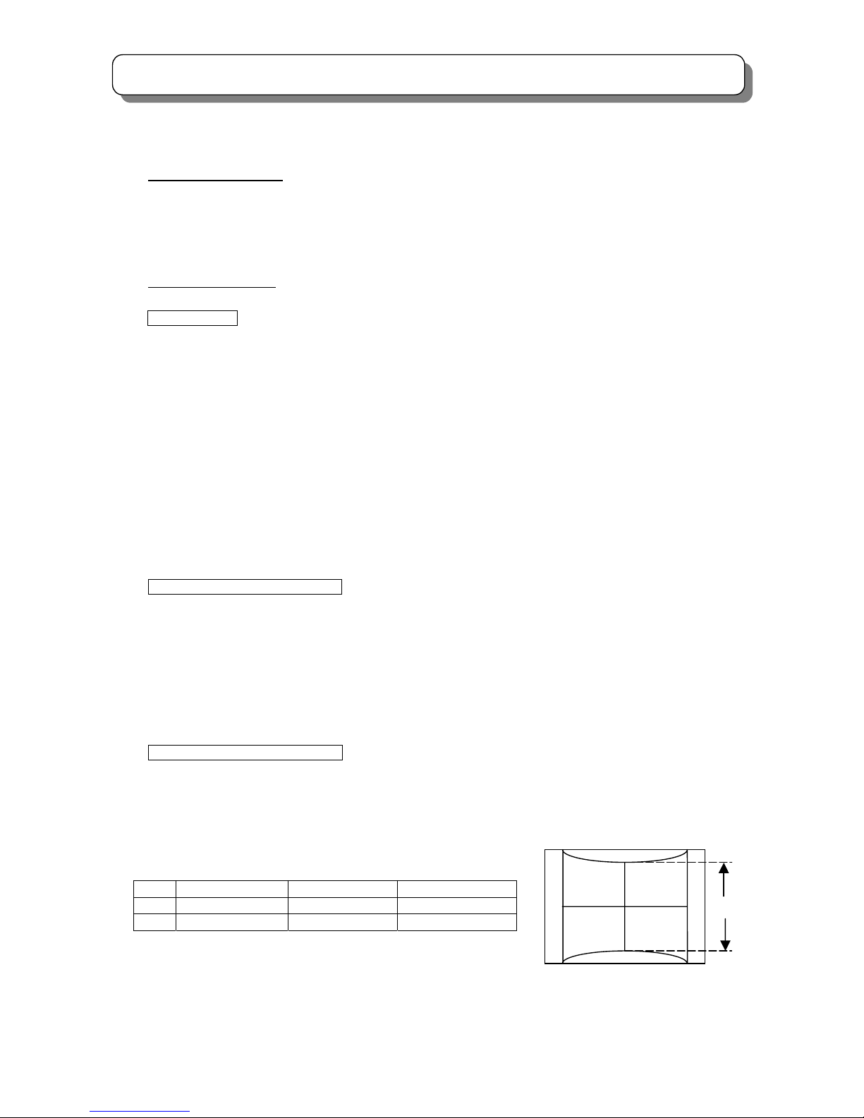
2.7 VERTICAL SIZE ADJUSTMENT
Adjustment Preparation
(1) VIDEO control should be set to Factory Preset condition.
(2) DCU ROM CHECK should be completed.
(3) Place the set facing east.
Adjustment Procedure
PAL 100i MODE I
2
C No.13
(1) Input any PAL signal.
(2) Press [MENU] key.
(3) Choose FUNCTION and SCAN, and set to 100Hz mode.
(4) Press [MENU] key to exit from FUNCTION.
(5) Press and hold the SERVICE ONLY SW. on CONV./FOCUS P.W.B. and [MUTE] key of Handset.
Green DCU cross-hatch are appeared with Conv. Data cleared.
(6) Press the input selector, then SERVICE MENU appears.
(7) Choose V.SIZE (amplitude) item by using Handset up/down cursor key.
(8) Adjust V.SIZE (amplitude) as following by using Handset left/right cursor key.
So that the distance between the topmost horizontal line and the bottommost horizontal line of DCU’s
cross-hatch pattern is L.
(9) Press [MUTE] key of handset to write the data.
(10) After adjustment, press SERVICE ONLY SW. for exit from SERVICE mode.
PAL 50Hz PROGRESSIVE MODE I
2
C No.17
(1) Input any PAL signal.
(2) Press [MENU] key.
(3) Choose FUNCTION and SCAN, and set to Progressive mode.
(4) Press [MENU] key to exit from FUNCTION.
(5) Adjust the same items as (5)-(10) of setting PAL 100i MODE.
NTSC 60Hz PROGRESSIVE MODE I
2
C No.21
(1) Input any NTSC signal.
(2) Adjust the same items as (5)-(10) of setting PAL 100i MODE.
Unit: mm Tolerance: ±5mm
L PAL 100i mode PAL 50p mode NTSC 60p mode
43” 525 525 560
50” 610 610 650
L
The distance between the topmost
horizontal line and the bottommost
horizontal line
Page 19
19
SERVICE ADJUSTMENTS
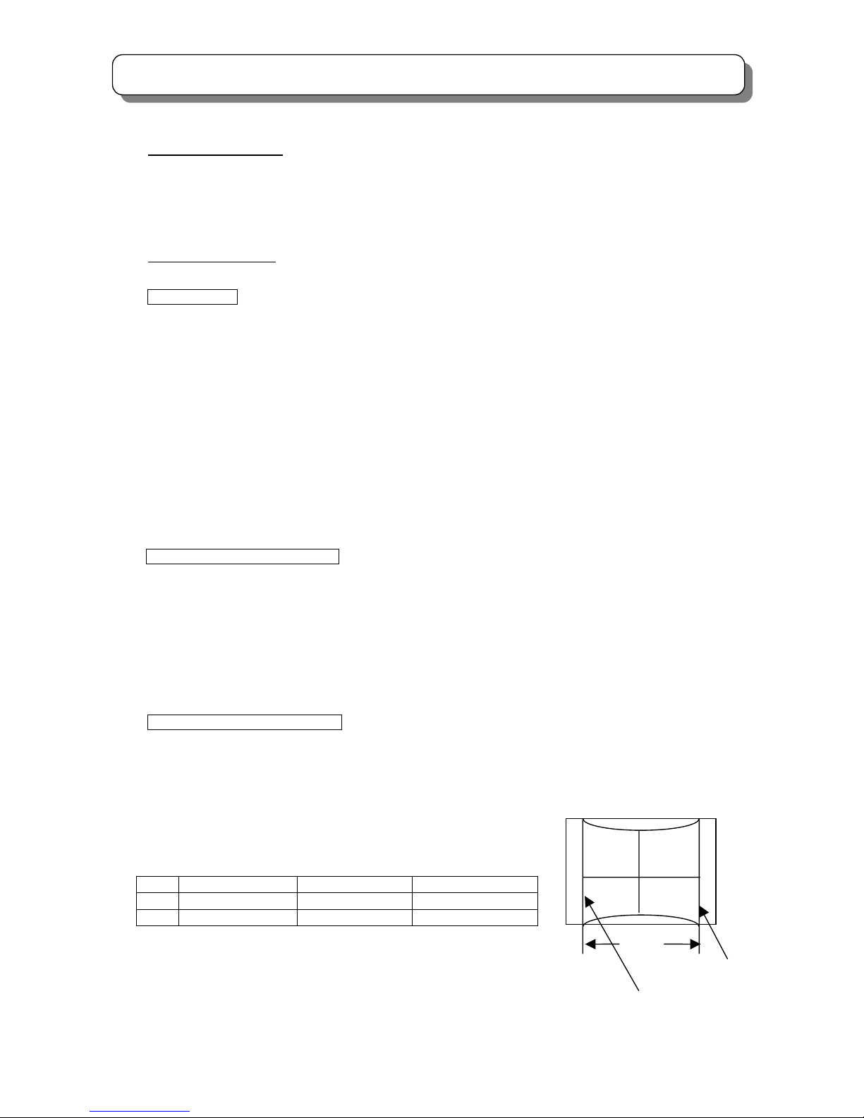
2.8 HORIZONTAL SIZE ADJUSTMENT
Adjustment Preparation
(1) VIDEO control should be set to Factory Preset condition.
(2) DCU ROM CHECK should be completed.
(3) Place the set facing east.
Adjustment Procedure
PAL 100i MODE I
2
C No.14
(1) Input any PAL signal.
(2) Press [MENU] key.
(3) Choose FUNCTION and SCAN, and set to 100Hz mode.
(4) Press [MENU] key twice to exit from FUNCTION.
(5) Press and hold the SERVICE ONLY SW. on CONV./FOCUS P.W.B. and [MUTE] key of Handset.
Green DCU cross-hatch are appeared with Conv. Data cleared.
(6) Press the input selector, then SERVICE MENU appears.
(7) Choose H.SIZE (EW SIZE) item by using Handset up/down cursor key.
(8) Adjust H.SIZE (EW SIZE) as following by using Handset left/right cursor key.
So that the distance between the left vertical line and the right vertical line of DCU’s cross-hatch
pattern is L.
(9) Press “MUTE” key of handset to write the data.
(10) After adjustment, press SERVICE ONLY SW. for exit from SERVICE mode.
PAL 50Hz PROGRESSIVE MODE I
2
C No. 18
(1) Input any PAL signal.
(2) Press [MENU] key.
(3) Choose FUNCTION and SCAN, and set to Progressive mode.
(4) Press [MENU] key to exit from FUNCTION.
(5) Adjust the same items as (5)-(10) of setting PAL 100i MODE.
NTSC 60Hz PROGRESSIVE MODE I
2
C No.22
(1) Input any NTSC signal.
(2) Adjust the same items as (5)-(10) of setting PAL 100i MODE.
Unit: mm Tolerance: ±5mm
L PAL 100i MODE PAL 50p MODE NTSC 60p MODE
43” 830 830 830
50” 965 965 965
L
The left line
The right line
Page 20
20
SERVICE ADJUSTMENTS
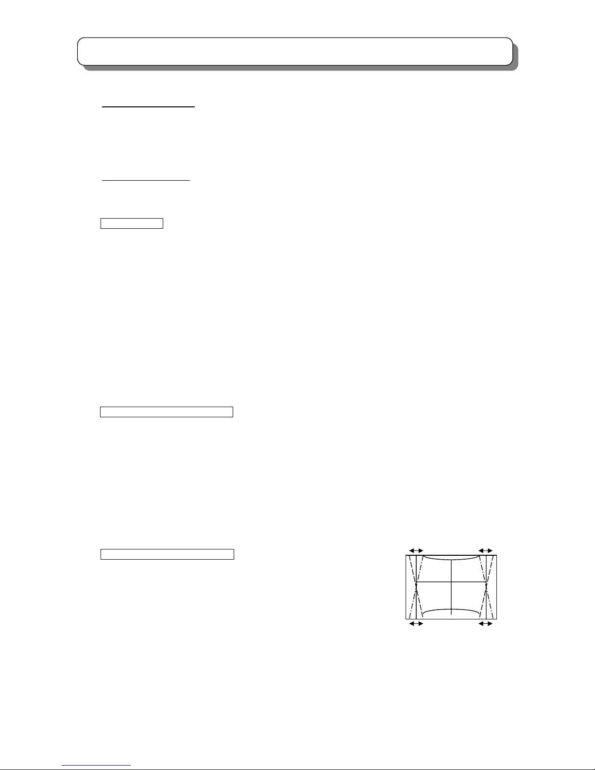
2.9 TRAPEZOID DISTORTION ADJUSTMENT
Adjustment Preparation
(1) VIDEO control should be set to Factory Preset condition.
(2) HORIZONTAL SIZE adjustment should be completed.
(3) Place the set facing east.
Adjustment Procedure
PAL 100i MODE I
2
C No.16
(1) Input any PAL signal.
(2) Press [MENU] key.
(3) Choose FUNCTION and SCAN, and set to 100i mode.
(4) Press [MENU] key twice to exit from FUNCTION.
(5) Press and hold the SERVICE ONLY SW. on CONV./FOCUS P.W.B. and [MUTE] key of Handset.
Green DCU cross-hatch are appeared with Conv. Data cleared.
(6) Press the input selector, then SERVICE MENU appears.
(7) Choose TRAPEZOID item by using Handset up/down cursor key.
(8) Adjust TRAPEZOID as following by using Handset left/right cursor key.
(9) Press “MUTE” key of handset to write the data.
(10) After adjustment, press SERVICE ONLY SW. for exit from SERVICE mode.
PAL 50Hz PROGRESSIVE MODE I
2
C No.20
(1) Input any PAL signal.
(2) Press [MENU] key.
(3) Choose FUNCTION and SCAN, and set to 50P mode.
(4) Press [MENU] key to exit from FUNCTION.
(5) Adjust the same items as (5)-(10) of setting PAL 100i MODE.
NTSC 60Hz PROGRESSIVE MODE I
2
C No.24
(1) Input any NTSC signal.
(2) Adjust the same items as (5)-(10) of setting PAL 100i MODE.
Vertical Screen frame line & edge
of vertical DCU cross-hatch line
should be parallel condition.
Page 21
21
SERVICE ADJUSTMENTS
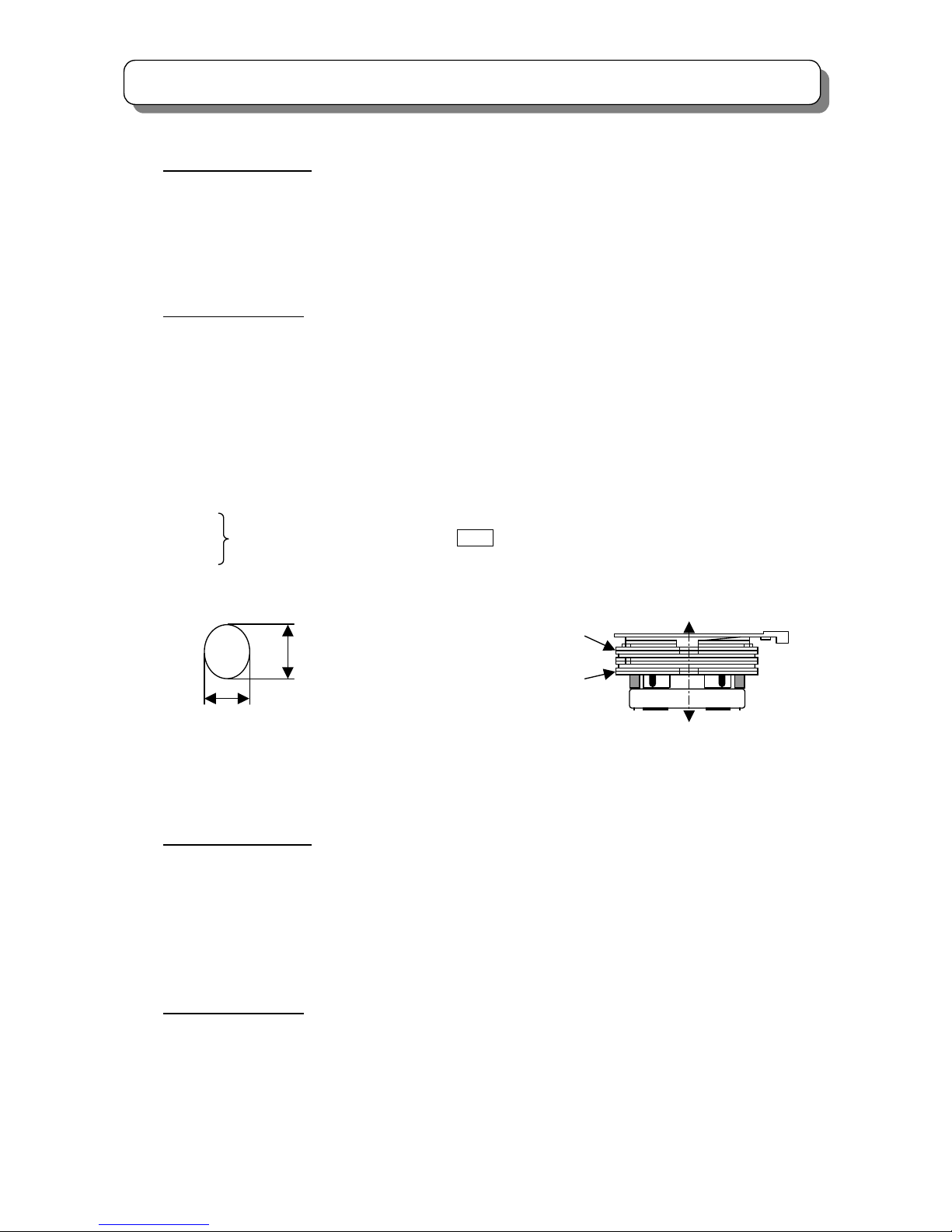
2.10 BEAM FORM ADJUSTMENT
Adjustment Preparation
(1) The beam alignment should have been completed.
(2) The raster inclination, centering, horizontal and vertical size adjustments should be completed. Optical focus
should be coarsely adjusted.
(3) VIDEO control should be set to Factory Preset condition. (Contrast: Max;other item: Center)
(4) Input the dot signal.
Adjustment Procedure
(1) Green PRT beam shape adjustment. Short-circuit 2P sub-mini connectors on Red and Blue CPT P.W.Bs. to
project only the green beam.
(2) Turn the green static VR
*1
fully clockwise.
Note : Blooming
(3) Make the dot at the screen center a true circle using the 4-pole magnet shown below.
(4) Repeat the procedure for the Red
*2
and Blue*3 PRT beam shapes
(5) After complete the adjustment, return R, G and B static VRs to the best focus point.
(6) After complete the beam alignment, fix the beam alignment magnet with white paint.
*1
*2 Static Focus VR is on FOCUS PACK UFPK
*3
2.11 LENS FOCUS ADJUSTMENT
Adjustment Preparation
(1) The orientation of PTV set is arbitrary, west, east, north and south.
(2) Centering DY inclination should be adjusted.
(3) Electrical focus adjustment should have been completed.
(4) Drive VR location adjustment should have been completed.(Red : 12 0’clock, Green : 1~2 0’clock)
(5) Receive the NTSC cross-hatch signal.
Contrast control should be set Center and Brightness control should be set minimum.
Adjustment Procedure
(1) Loosen the fixing screws or wing nuts on the lens cylinder so that the lens cylinder can be turned. (Be careful
not to loosen too much). After completing steps (4), (5), (6) below, tighten the fixing screws or wing nuts for
each lens with a torque of 0.67N.m(7Kgfcm) ~1.18N.m(12Kgfcm). (Do not turn the lens cylinder after tighten
the screws and wing nuts. Also do not over tighten the screw, otherwise the lens might be tilted or the screw
might be broken).
a
b
True circle specification
Specification : 0.9~1.1
True circle Form Ratio: a/b
PRT surface side
PRT E. gun side
4-pole beam shape
correction magnet
2-pole beam alignment
magnet
Page 22
22
SERVICE ADJUSTMENTS
Lens sass Lens sass
TYPE 1 TYPE 2
(2) Apply covers to colors of R, G and B lenses so as to project a single color beam on the screen and adjust in
sequence. (The adjustment order of R, G and B is only an example.)
(3) If the lens adjustment knob is turned clockwise (viewed from the front), the color aberration changes as
follows:
(4) In the case of G lens.
Set to the point where the chromatic aberration switches from blue to red. If the chromatic aberration
appearing all over the screen is not the same, observe the vertical bright line and adjust lens focus as specified
in table below. When the red chromatic aberration appearing at both sides of the bright line is not equal,
observe the side with larger chromatic aberration when adjusting.
HSA
SCB UNIT
SCREEN SIZE
43” 50”
INCH
L1 and L2
(PITCHES from CENTER)
3.0 3.0
CROSS-HATCH
PITCHES
BETWEEN
L1&L2
* *
I
*
(2mmMAX) * (2mmMAX)
COLOR
ABERRATION
O
**
(2mmMAX)
**
(2mmMAX)
REFER TO
NOTE BELOW
NOTE : * Slightly reddish or no color.
** Slightly bluish or no color.
Change the signal to the circular pattern and fine-adjust. Observe
the corners of the screen, especially the numbers in the small circle
when adjusting. If the focus performance at the screen center
exceeds the lower limit, it is acceptable.
NOTE1:
Since the G light is very important for picture quality and performance. Pay special attention in its adjustment. Be
careful not to touch the lens with your fingers when adjusting.
Color aberration
Cross-Hatch
Change of color aberration
Short focus Long focus
RED LENS Orange Scarlet
GREEN LENS Blue Red
BLUE LENS Purple Green
L1 L2
I O
Small circle of circle pattern
(NOTE 1)
Fixing screws
(NOTE 2)
Fixing Wing nuts
Page 23
23
SERVICE ADJUSTMENTS
(5) In the case of R lens.
Set the position where the chromatic aberration changes from red to crimson as shown below. Observe
the vertical bright line and adjust lens focus where the crimson or red chromatic aberration slightly
appears inside and crimson or red outside (reference value: 1~3mm) at the point specified in the table
below. Change the signal and fine-adjust in the same way as the G lens.
OPTICAL FOCUSING ADJUSTMENT RED
LENS HSA SCB UNIT
SCREEN SIZE
43” 50”
INCH
PITCHES from CENTER
6.0 7.0
CROSS-HATCH
PITCHES
SIDE
* *
I
*
(2mmMAX)* (2mmMAX)
COLOR
ABERRATION
O
**
(2mmMAX)
**
(2mmMAX)
REFER TO
NOTE BELOW
NOTE: * Slightly reddish or no color ** Slightly crimson or no color
NOTE 2: Adjust to the position such that Red and crimson is optimum.
(6) In the case of B lens.
Set the position where the chromatic aberration changes from purple to green as shown below.
Observe the vertical bright line and adjust lens focus where the purple or green chromatic aberration
slightly appears inside and purple or green outside (reference value: 1~3mm) at the point specified in the
table below. Change the signal and fine-adjust in the same way as the G lens.
LENS HSA SCB UNIT
SCREEN SIZE
43” 50”
INCH
PITCHES from CENTER
6.0 5.0
CROSS-HATCH
PITCHES
SIDE
* *
I
*
(2.0mmMAX)* (2.5mmMAX)
COLOR
ABERRATION
O
**
(2.0mmMAX)
**
(2.5mmMAX)
REFER TO
NOTE BELOW
NOTE: * Slightly purple or no color ** Slightly green or no color
NOTE 3: Setting to the center between purple and green is optimum.
(7) After all colors have been adjusted, display all colors with the cross-hatch pattern signal and compare the
focus (optical focus) performance with the limit sample set.
(8) Then, select the circular pattern signal and compare the focus (optical focus) performances of each color
and all colors together with the limit sample set.
(9) If the focus performance is worse than the limit sample set, re-adjust step (1) to (6).
L
I
O
L
I
O
Page 24

24
SERVICE ADJUSTMENTS
2.12 STATIC FOCUS ADJUSTMENT
Adjustment Preparation
(1) The raster inclination, centering, horizontal/vertical amplitude and optical/electrical focus and beam alignment
should be adjusted.
(2) The digital focus data should be cleared.
(3) Contrast control should be set maximum and brightness control should be set center.
(4) Receive the Hitachi circular pattern signal G24-CH.
(5) Apply covers to the others then adjusting lenses and project only single color on the screen.
Adjustment Procedure
(1) Red static focus adjustment: Vary the static focus VR on Focus pack (UFPK) (for red) so that the right edge of
Hitachi mark on the circular pattern is the clearest. Check that the focus does not get conspicuously worse at
other check point on the cross-hatch signal.
(2) Blue static focus adjustment: Vary the static focus VR on Focus pack (UFPK) (for blue) so that the Hitachi
mark on the circular pattern is the clearest. Check that the focus does not get conspicuously worse at all
edges of the cross-hatch signal.
(3) Green static focus adjustment: Vary the static focus VR on Focus pack (UFPK) (for green) so that the Hitachi
mark on the circular pattern center is t the clearest. Check that the focus does not get conspicuously worse at
the checking point on the periphery of picture and the cross-hatch signal.
Remarks
Checking point for the periphery of picture
2.13 DYNAMIC FOCUS CHECK
Preparation for Check
(1) The raster inclination, centering, horizontal/vertical amplitude and optical/electrical focus and beam alignment
should have been adjusted.
(2) The static convergence data should be cleared.
(3) Contrast control should be set maximum and brightness control should be set center.
(4) Receive the cross-hatch pattern signal.
Checking Procedure
(1) Short-circuit the sub mini connectors of Red (R) and Blue (B) on the CPT P.W.B. and project the Green (G)
color.
(2) Turn the static focus VR for Green (G) so that the picture center is just in focus.
(3) Check that the focus does not get conspicuously worse at all edges of the picture.
Checking point
Page 25
25
SERVICE ADJUSTMENTS
Checking points for horizontal direction:
Checking points for vertical direction:
Static focus VR for green is VR on Focus pack (UFPK).
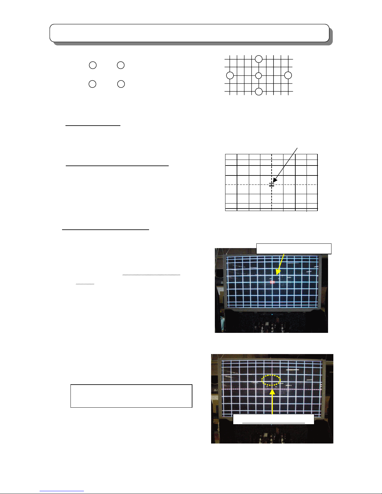
2.14 DIGITAL CONVERGENCE ADJUSTMENT
Preparation for Check
(1) Place the set facing east or west.
(2) Pre-heat 20 minutes or more before the adjustment.
(3) The horizontal/vertical amplitude should have been adjusted.
How to adjust by using remote controller
(1) Receive any PAL signal. (RF or VIDEO)
(2) Turn the set on and set it in PAL 100i mode.
(3) Push the “SERVICE ONLY” switch on the
CONVERGENCE/FOCUS P.W.B. to set digital convergence
unit to the adjustment mode.
* Adjustment Point Marker ON/OFF
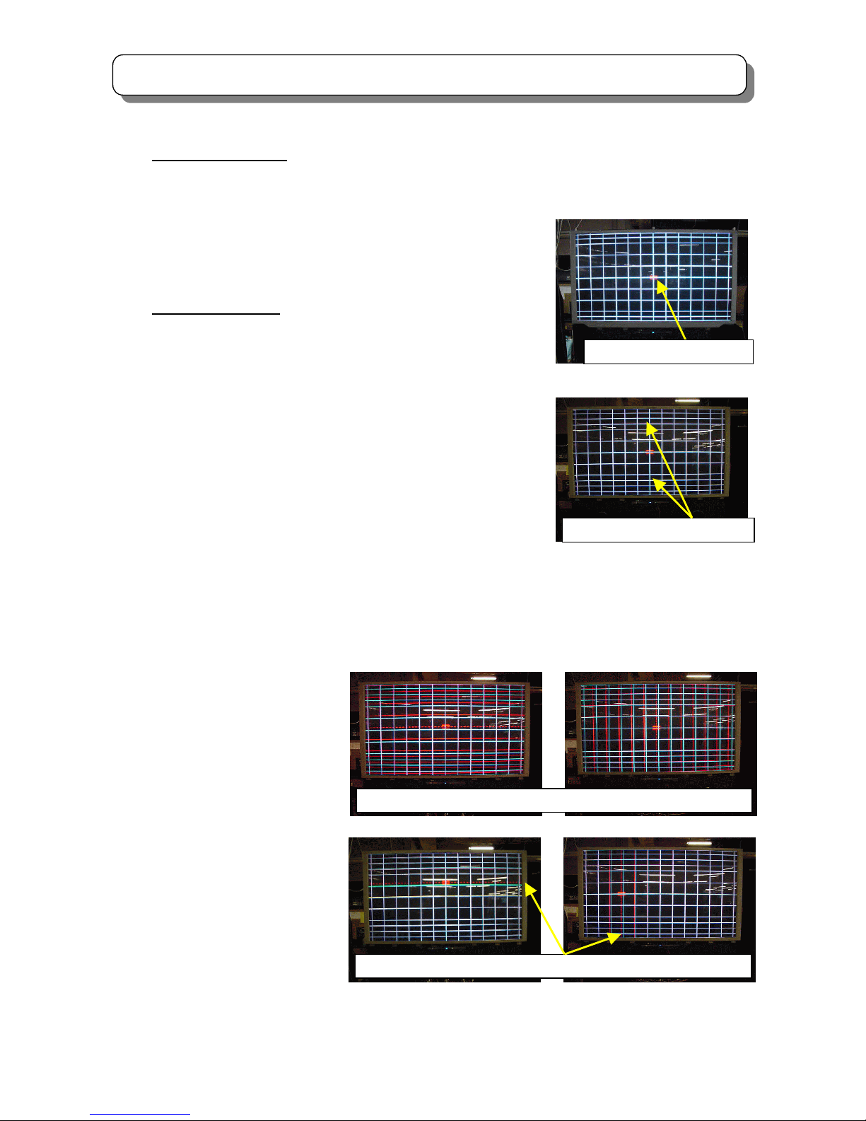
This function can improve view of adjustment point at CONVERGENCE adjustment mode.
a) Press Service Switch on Def/Conv. PWB to set to
CONVERGENCE adjustment mode, then display
Normal Crosshatch with "Adjustment Point
marker". (Fig.1)
b) Press [TV/TEXT] key on R/C, then display only
Normal Crosshatch, without "Adjustment Point
Marker". (Fig.2)
Adjustment Point is indicated as broken line
crossing.
c) Press [TV/TEXT] key on R/C again, then display
Normal Crosshatch with "Adjustment Point
Marker" again. (Fig.1)
(4) Phase Adjustment
See page 43, 27. DCU PHASE
(4) Phase Adjustment
See item “DCU PHASE DATA SETTING”.
3 9
6
12
C
3
9
6
12
A
djustment mode
A
djustment point
Maker is NOT displayed
Fig.1
Adj
ustment Point Marker
A
nd repeat procedure b) ~ c) by each press
[TV/TEXT] key on R/C.
Fig.2
Page 26

26
SERVICE ADJUSTMENTS
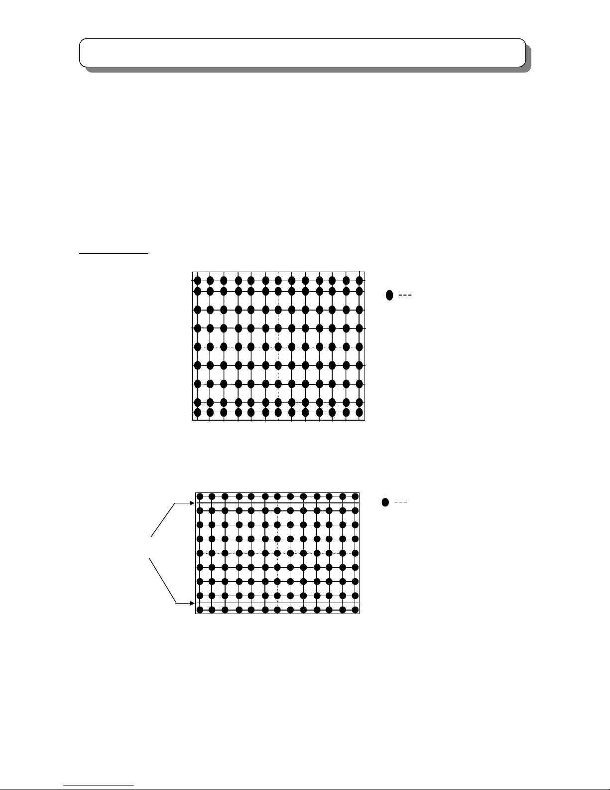
(5) Fine adjustment.
Adjustment points are 117 points. (H: 13 points x V: 9 points)
Adjustment points can be moved using [2], [4], [5], [6] keys. For better
result, adjust convergence from center to outside of the screen.
(6) Green convergence adjustment.
Press [▼/ CH down] key on R/C to select green convergence mode.
Adjust green cross-hatch line, using [▲], [▼], [◄], [►] (cursor) key.
(7) Red convergence adjustment.
Press [0] key on R/C to select red convergence mode. Adjust each red
line to green cross-hatch line, using [▲], [▼], [◄], [►] (cursor) key.
(8) Blue convergence adjustment.
Press [▲/ CH up] key on R/C to select blue convergence mode.
Adjust each blue line to green cross-hatch line, using [▲], [▼], [◄], [►]
(cursor) key.
(9) Calculation *
After complete convergence adjustment, press [MODE] key on R/C and the calculation mode starts. The
operation time takes about 2 seconds and no picture appears during this operation. This operation fills
convergence data between each adjustment points.
Check the mis-convergence; refer to
(Mis-convergence check)
. If you find mis-convergence more than this specification, adjust convergence
again.
(10) Write data to ROM
Press [INDEX] key on R/C.
First press, “ROM WRITE?” is displayed.
Second press, Data starts to write to ROM, this takes about 3 seconds and no picture appears during this
operation. If green dot pattern appears, writing operation has succeeded. Press [MUTE] key to return to the
adjustment mode. If red dot pattern appears, writing operation has failed. Replace digital convergence unit
and re-adjust. Push the “SERVICE ONLY” switch again to finish the adjustment.
* Step (9) ‘Calculation’ process can be omitted by pressing [MODE] key, because step (10) ‘ Write data to ROM’
process includes calculation process as well.
ROM WRITE by pressing [INDEX] key twice: ① Calculation process
② Writing data to ROM
(11) The digital convergence has 3 modes includes NTSC/60p , PAL/50p , PAL/100i. Change the other mode and
adjust again step (1) to (11) again.
NOTES:
(1) [CH Ⅰ/Ⅱ ] button……Cross-hatch/Video mode
Press [CH Ⅰ/Ⅱ ] 5 times to display external signal.
Press [CH Ⅰ/Ⅱ ] 5 times again to return to DCU internal cross-hatch.
(2) [MENU] button……….Remove color mode
Press [MENU] to switch between all colors displayed or adjustment color and Green only.
Press [0] then press [MENU], Red and Green displayed (Blue removed)
Press [▲/ CH UP] then press [MENU], Blue and Green displayed (Red removed)
Press [▼/ CH DOWN] then press [MENU], Only Green displayed
A
djustment point
Page 27
27
SERVICE ADJUSTMENTS
* Explanation of "Conv. For Outside Signal" function
(a) Press the “SERVICE ONLY” switch on DEF/Conv PWB, then
display "Normal Crosshatch". (Fig.1)
(b) Press [MENU] key on R/C, then display "Red + Green
Crosshatch with Red Marker" or "Green Crosshatch with
Green Marker" or "Blue + Green Crosshatch with Blue
Marker". (Fig.2)
(c) Press [MENU] key on R/C again, then display "Normal
Crosshatch" on Main Picture". (Fig.3)
(d) Press [MENU] key on R/C again, then display "Cross Marker
+ Box Marker " on Main Picture". (Fig.4)
(e) Press [MENU] key on R/C again, then display "only Box
Marker on Main Picture". (Fig.5)
(f) Press [MENU] key on R/C again, then display "Normal
Crosshatch" again. (Fig.1)
And repeat procedure (b) ~ (f) by each press [MENU] key on
R/C.
Fig.3
Marke
r
Fig.5 Fig.4
Marke
r
Marke
r
Fig.2
Fig.1
Marker (Adjustment point)
Marker
Page 28
28
SERVICE ADJUSTMENTS
(3) [SUB] button…raster position adjust
Adjustment preparation
a) Position adjustment...This will move an entire color. Use this adjustment to match colors at the center of
the screen.
b) Use the buttons below to switch color to adjust:
[▼/ CH down] : Green
[0]: Red
[▲/ CH up] : Blue
Adjustment procedure
a) Press the [SUB] button. Extra horizontal lines appear to confirm
raster position mode.
b) Use the cursor buttons to adjust position.
c) Press [SUB] again to exit from raster position mode.
Notes
: 1) Other functions cannot be accessed during the raster
position adjustment mode; Press [SUB] to exit from raster
position mode, and confirm extra horizontal lines are
disappeared.
2) Press [MENU] to switch between all colors displayed
or adjustment color and Green only.
*Convergence Data Adjustment Method
This function can adjust convergence data of all of one line (or all of screen) at the same time in
CONVERGENCE adjustment mode.
a) Press the “SERVICE ONLY” switch on DEF/Conv PWB to set to CONVERGENCE adjustment mode,
and then display Normal Crosshatch with Adjustment Point Marker. (Fig.1)
b) Press [SUB] key on R/C,
then the extra horizontal
lines appeared as set to
RATER POSITION
ADJUSTMENT MODE.
(Fig.2)
1) If Adjustment Point is
on center, by press
cursor key ([↑ ], [ ← ],
[↓], [→]) on R/C, then
Convergence Data of
all of screen are
exchanged at the same
time.
ex) Fig.3 (Fig.4) : By press [↑] ([←]) key on R/C, move up (left) RED convergence data of all of
screen.
Fig.2
Extra Horizontal line is added
Fig.4 Fig.3
Convergence Data (RED) of all of screen is exchanged.
Fig.6 Fig.5
Convergence Data (RED) of all of line is exchanged.
Fig.1
Adjustment Point Marker
Page 29
29
SERVICE ADJUSTMENTS
2) If the Adjustment point is not on center, by press cursor key on R/C, then Convergence Data of all of
one line include existing Adjustment Point Marker are exchanged at the same time.
ex) Fig.5 (Fig.6) : By press [↑] ([←]) key on R/C, move up
(left) RED convergence data of all of horizontal (vertical)
line include existing Adjustment Point Marker.
c) Press [SUB] key on R/C again to exit RATER POSITION ADJUSTMENT MODE.
Adjustment point
NOTE: PAL mode can be confirmed by extra horizontal lines.
A
djustment point
9 x 13 = 117 point
A
djustment point (NTSC 60p mode)
Extra horizontal line
A
djustment point
9 x 13 = 117 point
A
djustment point (PAL 50p,PAL 100i mode)
Page 30
30
SERVICE ADJUSTMENTS
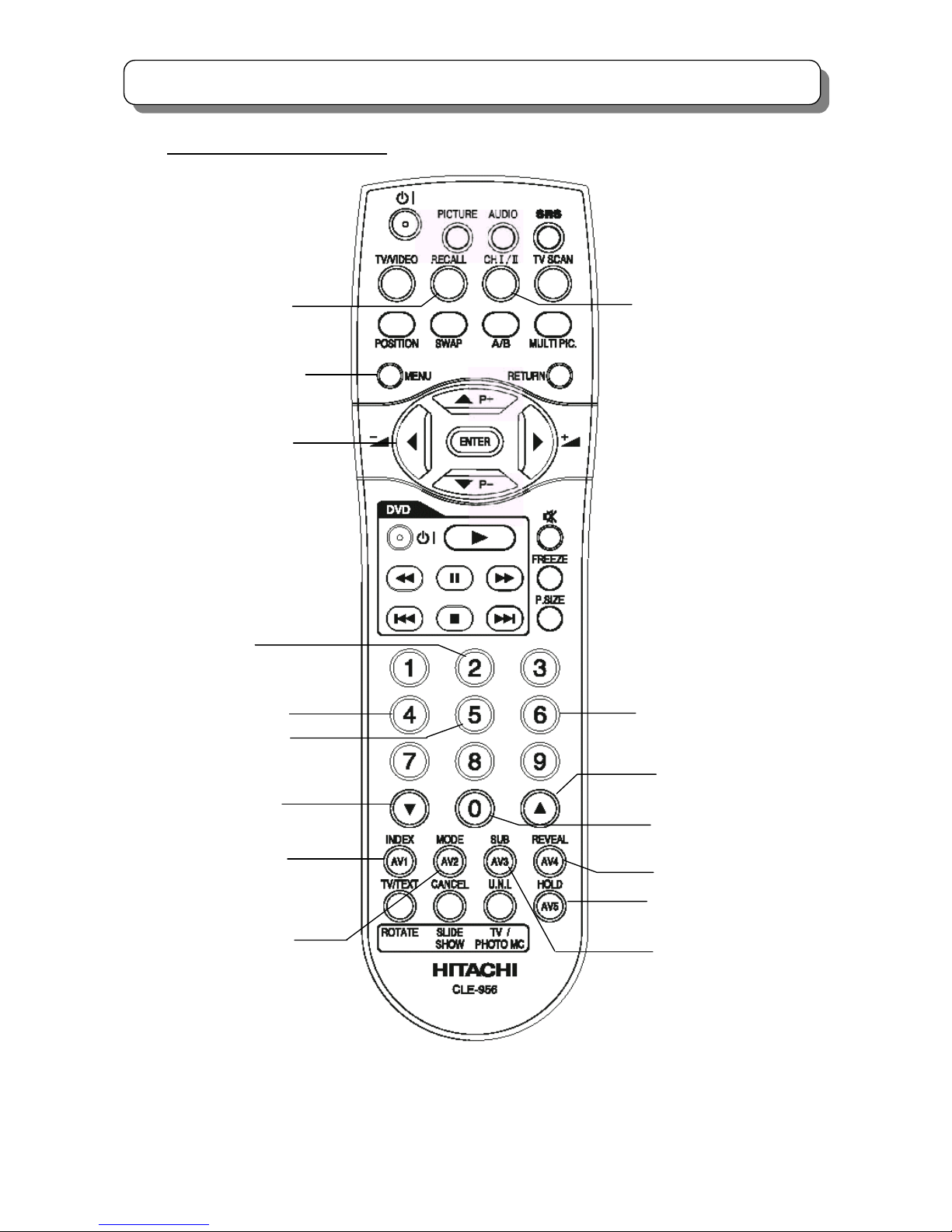
Digital convergence remote control
CURSOR UP
CURSOR LEFT
CURSOR DOWN
GREEN (3x3 ADJ.*)
REMOVE COLOR
A
DJUSTMENT
ROM WRITE
CURSOR RIGHT
RASTER POSITION
CALCULATION
INITIALIZE
PHASE
ROM READ
CROSSHATCH /
VIDEO MODE
BLUE (13×9 Fine ADJ.)
RED (5×7 ADJ.
)
NOTE: 3×3 Adjustment mode can be selected only after DCU uncorrected state.
(DCU uncorrected state: With the Power off, PRESS AND HOLD the Service Only button, then press the Powe
r
On/Off button at the same time until power is applied… Release Both.)
Page 31

31
SERVICE ADJUSTMENTS
Specification of digital convergence cross-hatch
4:3 NTSC 60p MODE
43” DIGITAL CONVERGENCE CROSSHATCH
50”
DIGITAL CONVERGENCE CROSSHATCH
UNIT:mm
876
10.2 10.2
2.0
73.3 83.9 83.9 73.3
2.0
654
71.3 71.3
83.9
71.3 71.3 71.3 71.3 71.3 71.3 71.3 71.3 71.3 71.3
83.9 83.9 83.9
UNIT:mm
1020
12.0 12.0
2.4
85.5 97.7 97.7 85.5
2.4
762
83.0 83.0
97.7
83.0 83.0 83.0 83.0 83.0 83.0 83.0 83.0 83.0 83.0
97.7 97.7 97.7
Page 32

32
SERVICE ADJUSTMENTS
4:3 PAL 100i MODE
43”
DIGITAL CONVERGENCE CROSSHATCH
50”
DIGITAL CONVERGENCE CROSSHATCH
UNIT:mm
876
5.0
78.1
9.6
654
78.1
3.0 3.0
72.5 72.5
72.5 72.5 72.5 72.5 72.5 72.5 72.5 72.5 72.5 72.5
78.1 78.1 78.1
9.6
5.0
78.1
78.1 78.1
UNIT:mm
1020
5.8
91.0
11.2
762
91.0
3.6 3.6
84.4 84.4
84.4
91.0 91.0 91.0
11.2
5.8
91.0
91.0 91.0
84.484.484.484.484.484.484.484.484.4
Page 33

33
SERVICE ADJUSTMENTS
4:3 PAL 50p MODE
43”
DIGITAL CONVERGENCE CROSSHATCH
50”
DIGITAL CONVERGENCE CROSSHATCH
UNIT:mm
1020
5.8
91.0
11.2
762
91.0
3.6 3.6
84.4 84.4
84.4
91.0 91.0 91.0
11.2
5.8
91.0
91.0 91.0
84.484.484.484.484.484.484.484.484.4
UNIT:mm
876
5.0
78.1
9.6
654
78.1
3.0 3.0
72.5 72.5
72.5 72.5 72.5 72.5 72.5 72.5 72.5 72.5 72.5 72.5
78.1 78.1 78.1
9.6
5.0
78.1
78.1 78.1
Page 34

34
SERVICE ADJUSTMENTS
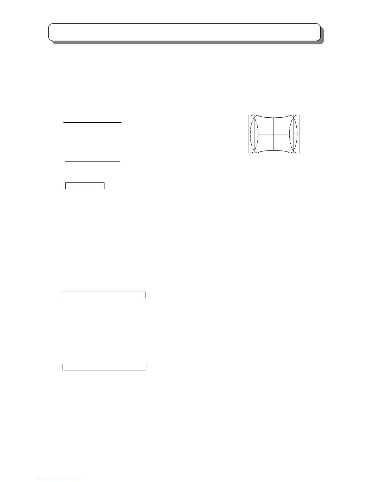
2.15 SCANNING AREA CHECK
Checking condition
(1) Digital convergence adjustment should be completed.(PA L、NTSC)
(2) Receive the Hitachi circle pattern signal. (PAL 、NTSC)
(3) Contrast and Brightness should be set Factory Preset condition.
(Contrast : max Other controls : Center position)
(4) Check that the scanning area matches with the next drawing.
(5) The digital convergence has 3 modes. Change the other mode then check again.
(6) Check the horizontal center position. If the center is shifted, readjust to center position.
*Service menu No.70 : Horizontal position for PAL 100i mode.
No.71 : Horizontal position for PAL 50p mode.
No.72 : Horizontal position for NTSC 60p mode.
Page 35

35
SERVICE ADJUSTMENTS
Inner edge of the circle
H size marker
0.7~2
Outer edge of the circle
H size marker
0.7~2
53
35
Top and bottom of the circle is between outer edge and inner edge.
PAL 100i/PAL 50p/NTSC MODE
Page 36

36
SERVICE ADJUSTMENTS
2.16 BLUE DEFOCUS ADJUSTMENT
Adjustment Preparation
(1) Optical and electrical focus adjustment should be completed.
(2) The convergence adjustment should be completed.
(3) VIDEO control should be set to Factory Preset condition. (Contrast: maximum; Other items: center)
Adjustment Procedure
(1) Input cross-hatch signal to VIDEO or RF input.
(2) Turn the B FOCUS VR fully clockwise.
(3) If blue does not satisfy specification as shown in the table below, adjust it by turning the B FOCUS VR
counterclockwise.
Blue Defocus Luminance
CHASSIS DP3M UNIT
Screen size 43” 50” INCH
Blue out of specification 1.5 1.5 mm
Note: The view point should be limited to the center of the screen for this adjustment. (FOB 0.0)
2.17 WHITE BALANCE ADJUSTMENT
2.17.1 CHECK CUT OFF ADJUSTMENT
Adjustment Preparation
(1) Pre heat-run should be completed.
Adjustment Procedure
(1) Go to “SERVICE item No.10” and press [►] key to enter CUT OFF adjustment mode by using JIG R/C.
(2) Check that each line just appears.
(3) If some of lines are brighter or darker than others, apply CUT OFF adjustment again.
(4) Press [◄] key to return normal mode.
2.17.2 WHITE BALANCE ADJUSTMENT
Adjustment Preparation
(1) Pre-heat 20 minutes or more before the adjustment.
(2) VIDEO control should be set to Factory Preset condition. (Contrast: maximum; others: center)
(3) Color temp. : COOL
(4) Signal: High Light white balance adjustment: WHOLE WHITE 100 IRE
Low Light white balance adjustment: WHOLE WHITE 25 IRE
Blue out of specification
High brightness white balance Low brightness white balance
Service mode Item No. Service mode Item No.
Red : (R DRV) 45 Red : (R cut OFF) 47
Green: (G DRV) 46 Green: (G cut OFF) 48
Blue : (B cut OFF) 49
Sub Brightness should be adjusted roughly
before adjust the white balance.
Page 37

37
SERVICE ADJUSTMENTS
※ COMPONENT INPUT (input Y signal to “Y” terminal of AV1& insert a connector without signal to the
“P
R”
terminal of AV1)should be used in order to reduce digital noise.
※ Use signal without color burst. If it is not possible, use PAL signal and turn off comb filter in User Menu.
(5) BLUE defocus adjustment should be finished.
(6) The vertical incident illumination on the screen should be 20 lux or less.
Adjustment procedure
A) High Light W/B adjustment:
(1) Receive signal for High Light white balance adjustment.
(2) Adjust the white balance to 14000K+0MPCD (X, Y) = (0.266,0.270) at the screen center by using JIG R/C.
Use item No. 45 (R DRV) to adjust X, item No. 46 (G DRV) to adjust Y.
B) Low Light W/B adjustment
(1) Receive signal for Low Light white balance adjustment.
(2) Adjust the white balance to (X, Y) = (0.266,0.270) by using R/C. Use item No.47 (R CUT OFF) to adjust X,
item No.49 (B CUT OFF) to adjust X &Y. Do not change the item No.48 (G CUT OFF) setting.
C) Repeat A & B two or three times.
(Press [MUTE] button on the R/C when adjustment has completed.)
White balance adjustment flowchart
FINISH
Cut off Adj
Sub Brightness Adj (roughly)
If Bluish
Check
Low light W/B
Adjust Low light W/B
Adjust High light W/B
sub brightness Adj
START
Repeat two or three times, until no
adjustment is needed
Check
Low light W/B
High light W/B
Sub brightness
If NG
If OK
BLUE defocus Adj
Page 38

38
SERVICE ADJUSTMENTS
2.18 SUB BRIGHTNESS ADJUSTMENT
Adjustment Preparation
(1) Pre-heat 20 minutes or more before the adjustment.
(2) Receive the color bar signal.
(3) The vertical incident illumination on the screen should be 20 lux or less.
Adjustment Procedure
(1) Go to “Sub Brightness (item No. 44)” in adjustment mode by using JIG R/C.
(2) Adjust Sub brightness following the specification as shown below by using JIG. R/C.
(3) Press [MUTE] key on R/C to write the data into ROM.
REMARKS
Observe the TV SET screen directly by eye; Do not use a mirror.
Adjustment specification: Within ± 0.3 step
Quality control specification: Within ± 0.5 step
Note: During the SUB-BRIGHTNESS adjustment mode, TV Micron IC changes the CONTRAST and the COLOR
controls to Minimum, but the other controls are not changed automatically.
Make sure that the other controls are set center.
CHASSIS Sink to black Slightly for black
DP3M A0 A1
Note: Actual procedure, set A1 portion to black (same level as A0 portion) and reduce 6 steps to set A1 portion
slightly brighter.
A0 A1 A2A3A4A5A6A7A8A
9
A10
Page 39

39
SERVICE ADJUSTMENTS
2.19 SUB PICTURE WHITE BALANCE ADJUSTMENT
Adjustment Procedure
(1) Observe P852 on the CPT P.W.B. and change the SUB CONTRAST (Item No. 61) of service mode by
using jig R/C and adjust so that the amplitude of the sub-picture is the same as that of the main-picture.
(shown on below)
(2) Press [MUTE] key to write the data.
* Adjustment specification : ±1V
* Quality control specification : ±3V
* Wave form of P852 = Cathode
(Sub picture level compared with main picture level)
* Perform this adjustment after the white balance and sub-brightness adjustments of the main picture are
completed.
* White balance 14000K±0 MPCD (Color coordinates: x=0.266 y=0.270)
2.20 TINT ADJUSTMENT
(1) Preparation
Pre heat run should be finished.
(2) Input window pattern signal like below to the AV3 and AV4.
1H
CATHODE WAVE FORM
WHITE (CATHODE VOLTAGE)
MAIN PICTURE
1/2H
1/2V
INT Y = 0%
EXT Y = 0%
INT C = 100%
EXT C = 100%
INT C = -90°
EXT C = +90°
Page 40

40
SERVICE ADJUSTMENTS
(3) Enter to split mode and display AV3 and AV4.
(4) Enter to service mode.
(5) Observe “B” cathode and adjust the INT level and EXT level.
Item 64 for main, item 65 for sub.
Press [MUTE] key on R/C to write the data into ROM.
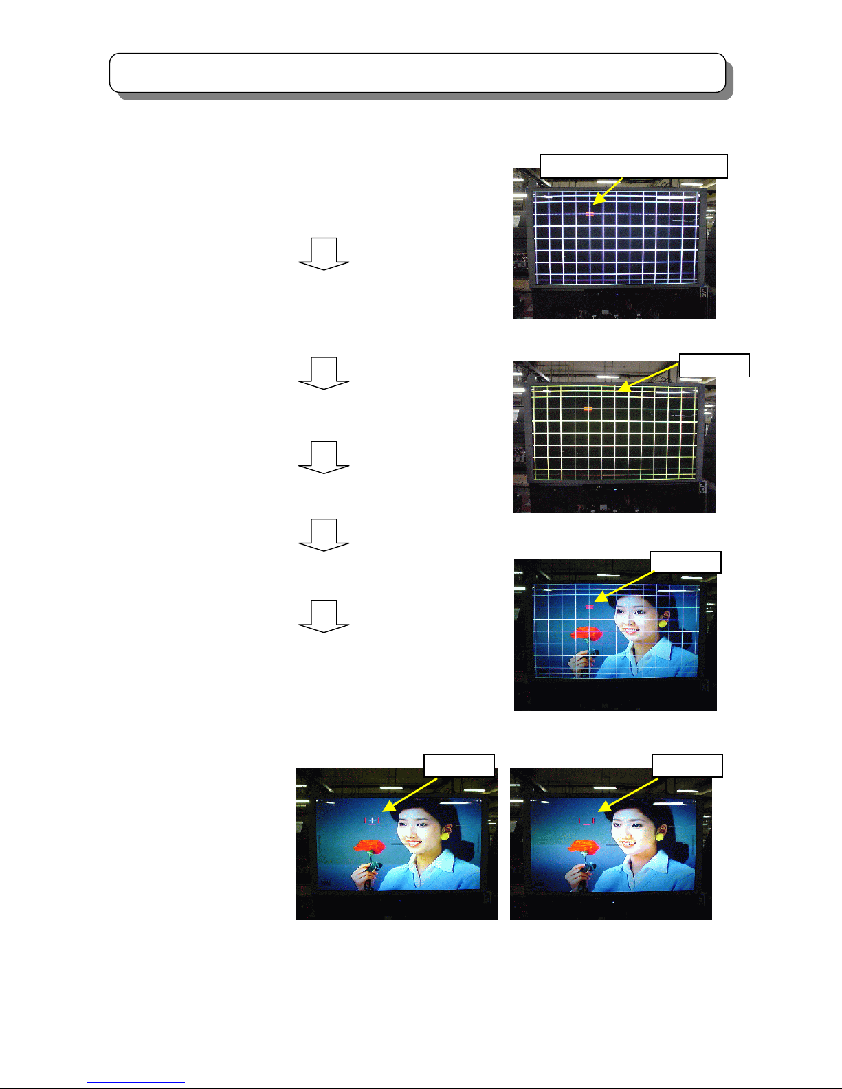
2.21 MAGIC FOCUS INITIALIZE
2.21.1 MAGIC FOCUS INITIALIZE
Adjustment Preparation
(1) Receive the PAL cross-hatch or PAL circle pattern signal and set 100Hz mode.
(2) Digital convergence adjustment should be completed.
Adjustment Procedure
(1) Press the R/C Jig. command (Jig code: 509E) to start initialize operation.
(2) Several windows appear during this operation. It takes about 45 seconds by green dots appear after
initialize operation is completed.
(3) Check that green dots appear.
(4) Turn the power switch off.
(5) Change the PAL 50p mode and repeat the procedure (1) - (3) for PAL50p mode.
(6) Change the signal to NTSC circle pattern and repeat the procedure (1) - (3) for the NTSC 60p mode.
Initialize operation
OSD: PAL 100i mode *INITIAL:1*
PAL 50P mode *INITIAL:5*
NTSC 60P mode *INITIAL:6*
NOTE: The digital convergence has 3 modes NTSC 60p, PAL 100i, PAL 50p.
Therefore this adjustment needs 3 modes.
REMARKS Another way to start the initialize operation:
(1) Press ”SERVICE ONLY” SW on CONVER/FOCUS P.W.B. to set DCU the adjustment mode.
(2) Press [INDEX] key on R/C. Then “ROM WRITE?” message is displayed to confirm the ROM writing.
(3) Press [ RECALL ] key on R/C to cancel the ROM writing and start initialization.
It takes about 45 seconds by green dots appear after initialization is completed.
(4) Check that green dots appear.
*INITIAL: 6*
Page 41

41
SERVICE ADJUSTMENTS
Note: If any error message (red) appears, refer to “CONVERGENCE ERRORS”.
CONVERGENCE ERRORS
If there is an error while performing INITIALIZE or MAGIC FOCUS, error code or message appears on the
screen as shown on the following table.
When MAGIC FOCUS operates: Error code (‘GREEN’) appears for about 1 second in bottom right corner, and
then returns to RF or video signal.
When INITIALIZE operates: Error message (RED) appears all the time.
REMARKS *1) Relation of sensor No. and screen position as shown below:
Error
Code
Error Massage Contents Countermeasure/ Check method
1 VF ERROR ! EEPROM Write Error
2
CONNECT1 !
No.01234567
OVER FLOW !
No.01234567 *1
Connection Check Error
(Pattern is not detected)
3
A/D LEVEL !
No.01234567
OVER FLOW !
No.01234567 *1
Calibration Error
(Small difference between
High and Low brightness)
Replace the DCU
Darken outside light
Check the placement of the sensor Is pattern hitting
to sensor?
Check connection and solder bridge of sensor
Replace the sensor
Sensor connector check
Sensor P.W.B. check
Adjustment check (H/V size, centering)
4 OVER FLOW !
Data over flow Error
(Saturation of corr. Dada)
5
Convergence
error(The number of
adjustment times is
more than setting.)
Convergence Error
(The number of ADJ. Times
is more than setting.)
Check the placement of the sensor
Adjustment check
(H/V size, centering)
Convergence AMP circuit check
6 LOOP COUNT ! Not use
7 OPERATION ! Make setup data error Same as error code 4
8 CHECK SUM ! Deferent SRAM-EEPROM Replace the DCU
9
CONNECT2 !
No.01234567 *1
Connect data set error(ADJ.
Parameter PORT80-87 Is
Wrong setting)
Same as error code 2
10 NOISE ! Sensor noise error
Input strong field strength signal
Check the wire dressing of connector between
sensor and DCU.
11 SYNC ! H BLK, V BLK error
Input strong field strength signal
Input standard signal NTSC or PAL
0 1 2
6 5 4
7 3
On screen
(View from front side)
sensor No. 0-7
Page 42

42
SERVICE ADJUSTMENTS
3. ADJUSTMENT POINT
3.1 PRT CABINET LOCATIONS
FRONT
3.2 FOCUS PACK
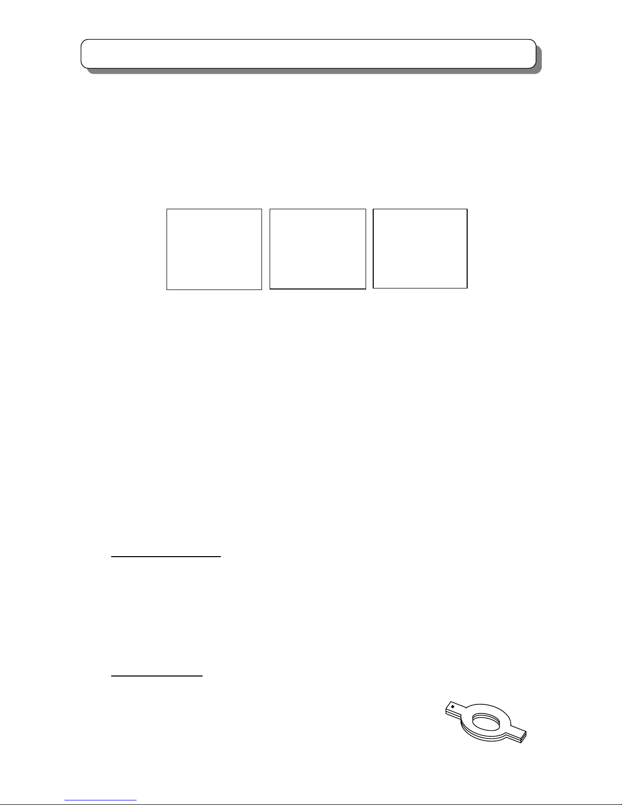
(4) 4-POLE MAGNET FOR BEAM FORM ADJUSTMENT
(5) BEAM ALIGNMENT MAGNET
(6) FOCUS PACK
(1) CENTERING MAGNET FOR RED PRT
(2) CENTERING MAGNET FOR GREEN PRT
(3) CENTERING MAGNET FOR BLUE PRT
R G B
FOCUS PACK
SCREEN GREEN
SCREEN BLUE
FOCUS BLUE
SCREEN RED
FOCUS GREEN
FOCUS RED
1 4 3
2
5
46
5
Page 43

43
SERVICE ADJUSTMENTS
3.3 MAIN P.W.B.
(1) SIGNAL P.W.B.
PSC
PH12P
PBS
VH12P
PAS1
EH10P
PFSH2
EH2P
PFSH1
PH10P
PFS
EH13P
PRST
PH2P
PJIG
EH7P
I501
I001
TERMINAL
PWB
(PIP)
U401
FLEX
CONTROL
SUB SIGNAL
PWB
U301
U302
Main
Tune
r
Sub
Tune
r
Look down view
Page 44

44
SERVICE ADJUSTMENTS
(2) SIGNAL SUB P.W.B.
IG02
IS02
IS01
IT01
IQ01
IG01
Look down view
Page 45

45
SERVICE ADJUSTMENTS
REAR VIEW
(3) DEFLECTION/CONVERGENCE P.W.B.
Look down view
DIGITAL
CONVERGENCE
“SERVICE ONLY” switch
SK01
DF1
I601
MB MG MR
Q701
IK04
IK05
TH01
QH01
Q777
PAD J
XA6P
D708
RH17
SUB DEF. PWB
Q712
Page 46

46
SERVICE ADJUSTMENTS
(4) CPT/CONTROL/LED P.W.B.
(5) CONTROL P.W.B.
(6) LED P.W.B.
P852
(Cathode)
P851
E851
GND
GREEN
3 1
P802
(
Cathode
)
P801
E801
GND
RED
3 1
P8A1
E8
A
GND
BLUE
3 1
P8A2
(Cathode)
CPT P.W.B.
(16:9 MODEL)
MENU
VOL-DOWN
CH-UP
VOL-UP
CH-DOWN
IR RECEIVER
PPL1
PCC1
PFS
POWER LED(BLUE)
PHOTO MC LED(GREEN)
TV/VIDEO
CONTROL P.W.B.
PLL2
BLUE LED
LED P.W.B.
Page 47

47
SERVICE ADJUSTMENTS
(5) AV INPUT P.W.B.
(6) AC SW P.W.B.
(7) AutoPower P.W.B ( Only for 191,982)
INPUT 5
S
MAIN
HEAD PHONE
L R V
SUB
HEAD PHONE
MAGIC
F
OCUS
PF1
PCC2
PFN
PCIA
PCIB
I9X1
R9XB
R9XA
R9XD
R9XC
Q9X1
PPX2
PPX1
Page 48

48
SERVICE ADJUSTMENTS
(8) DP3M POWER P.W.B.
IAA1
PPS1 PPS3 PPS4 PPS5 PPS6
PSP
PPD3
PPD1
PPD4 PPD1
PPC1
D901
S901
D956
Audio
E903
+220V
U901
I901
F9C1
FUSE
F903
FUSE
T901
Switching Transformer
D955
SW+5.5V
D913
SBY+5V
D912
Main
Power
I902
ACK
I903
FB
D932
+B
E907
+B
E906
+B Reg
E905
-28V
E901
Audio
E904
+28V
EAG1
Audio-GND
PPC2
Stand-by
Module
Main Power SW
Back Cover Side
(Green)
(Green)
(Green)
(Green)
(Red)
E902
+10V
PPS2
PPD2
PC1
PC2
China Model
onl
y
Page 49

49
SERVICE ADJUSTMENTS
4. SERVICE MENU
4.1 ADJUSTMENT PROCEDURE
(1) Receive signal on main picture, then turn off the main power.
(2) Press and hold the [TV/VIDEO] button on Control Panel and then Power ON to access service
adjustment mode. (Hold the [TV/VIDEO] button until service menu appears.)
(3) Adjust required items by the following table. Select item by [▲] or [▼] button on remote handset and
adjust by [►] or [◄] button.
(4) Press [MUTE] button to memorize the value.
4.2 SERVICE MENU(V203)
4.21 Below items are for service adjustment (Don’t change other items except for below.)
FACTORY ADJ. ADJUSTMENT DETAILS
No.
CODE MODE ITEM MODE
ADJ.
RANGE
INITIAL
DATA
IC
0 00 1 CH_PRESET - 0~2 0 -
1 01 1 Model Identification 1:ASPECT - 0~1 0 -
2 02 1 Model Identification 2:HD - 0~1 0 -
3 03 1 Model Identification 3:MULTI PICTURE - 0~1 0 -
4 04 1 Model Identification 4:Destination - 0~2 0 -
5 05 1 Model Identification 5:OSD Language - 0~2 0 -
6 06 1
Model Identification 6 : SOUND_SYSTEM /
COLOR_SYSTEM
- 0~5 0 -
7 07 1 Model Identification 7:TEXT - 0~8 0 -
8 08 1 Model Identification 8:MC - 0~1 0 -
9 09 1 Model Identification 9:LIGHT - 0~1 0 -
10 0A 1 CUT_OFF ADJ. - 0~1 0 -
11 0B 1 AGC ADJ. MAIN 0~255 75 CXA1875
12 0C 1 AGC ADJ. SUB 0~255 120 CXA1875
13 0D 1 V_SIZE Deflection Mode 1 0~127 38 TA1317AN
14 0E 1 H_SIZE Deflection Mode 1 0~127 53 TA1317AN
15 0F 1 Parabola Modification Deflection Mode 1 0~63 25 TA1317AN
16 10 1 Side Pin Symmetry Modification Deflection Mode 1 0~127 66 TA1317AN
17 11 1 V SIZE Deflection Mode 2 0~127 24 TA1317AN
18 12 1 H SIZE Deflection Mode 2 0~127 53 TA1317AN
19 13 1 Parabola Modification Deflection Mode 2 0~63 26 TA1317AN
20 14 1 Side Pin Symmetry Modification Deflection Mode 2 0~127 65 TA1317AN
21 15 1 V SIZE Deflection Mode 3/5 0~127 23 TA1317AN
22 16 1 H SIZE Deflection Mode 3/5 0~127 33 TA1317AN
23 17 1 Parabola Modification Deflection Mode 3/5 0~63 24 TA1317AN
24 18 1 Side Pin Symmetry Modification Deflection Mode 3/5 0~127 62 TA1317AN
25 19 1 V SIZE Deflection Mode 4 0~127 0 TA1317AN
26 1A 1 H SIZE Deflection Mode 4 0~127 6 TA1317AN
27 1B 1 Parabola Modification Deflection Mode 4 0~63 20 TA1317AN
28 1C 1 Side Pin Symmetry Modification Deflection Mode 4 0~127 47 TA1317AN
44 2C 1 SUB BRIGHTNESS TEXT 以外 0~255 127 TA1360AN
45 2D 1 R_DRIVE COOL 0~127 63 TA1360AN
46 2E 1 G_DRIVE COOL 0~127 63 TA1360AN
47 2F 1 R_CUT_OFF COOL 0~255 127 TA1360AN
48 30 1 G_CUT_OFF COOL 0~255 127 TA1360AN
49 31 1 B_CUT_OFF COOL 0~255 127 TA1360AN
61 3D 1 SUB_CONTRAST SUB 0~15 10 TB1274
64 40 1 TINT MAIN 0~63 32 TB1274
65 41 1 TINT SUB 0~63 32 TB1274
70 46 1 HORIZONTAL_POSITION Deflection Mode 1 0~127 80 TA1360AN
71 47 1 HORIZONTAL_POSITION Deflection Mode 2 0~127 79 TA1360AN
72 48 1 HORIZONTAL_POSITION Deflection Mode 3 0~127 70 TA1360AN
73 49 1 HORIZONTAL_POSITION Deflection Mode 4 0~127 71 TA1360AN
74 4A 1 HORIZONTAL_POSITION Deflection Mode 5 0~127 71 TA1360AN
611 - - SET1 Factory preset condition - - -
612 - - SET2 EEPROM data initialize - - -
Page 50

50
SERVICE ADJUSTMENTS
4.21 Below items should be reset then start to adjust if you change E2PROM(I003)
No. ITEM MODE Initialize C43- FD5000 C50- FD5000
102 SHARPNESS Center AV 48 60 60
147 APACON_PEAK_FREQ PAL 2 1 1
149 APACON_PEAK_FREQ Component 0 1 1
150 APCON_PEAK_FREQ HD 0 1 1
179 Y_DETAIL_CONTROL PAL 8 12 12
180 Y_DETAIL_CONTROL NTSC 10 12 12
182 Y_DETAIL_CONTROL 1080i_50/1080i/60/720p/MC 13 11 11
310 MAIN_YNR_PASSAGE_LEVEL -
1 0 0
357 Y_V_H_ENHANCE_GAIN Composite Video
10 6 6
359 Y_V_H_ENHANCE_GAIN 1080i_50/1080i/60/720p/MC 5 2 2
※Press MUTE key to save if you change data.
Page 51

51
TROUBLE SHOOTING
Check
Is Power LED
(D913,Green)
“ON”?
Is click sound
of Relay(S901)
heard?
Does Red LED
(D912) “ON”,”BLINK”
or “OFF”?
1. Turn OFF the power SW.
2. Wait for 3 seconds.
3. Turn ON again after several
seconds,and observe
green LEDs carefully.
Are 4 Green LEDs
turned OFF at the
same t ime ?
PWB connecter
(PPS5) open.
SW+115V line
E907, D932,
D925, Q777,
QH01, Q701,
TH01, T701
etc.
SW+28V line
E904, D922,
etc.
SW+5.5V line
D955, I905,
etc.
Audio line
D956, E901,
D915, IAA1,
etc.
U901, D902,
etc.
SBY+5V line
I009, I001,
etc.
E907,
etc.
Check Chec k
Check
Check
No
Raster
Is Voltage at
pin(4) of I901
14V-20V?
Has Fuse F903
blown?
D911, R906,
R907, C911
I901, D901,
R902
YES
YES
YES
YES
OFF
YES
NO
NO
BLINK
YES
NO
Is base Voltage
Of Q709 normal?
Does raster
Appear with (6) and (5)
Of PPD4 shorted?
Are Voltages
At both ends of T702
(primary side)
normal?
I501 pin(37)
-H out,
I503 pin(31)
-DEF Hvcc
etc.
T702, R748,
R730
etc.
Q777, QH01,
T701, TH01
etc.
NONO
NO
YES
YES
Is Voltage
at pin(16) of I001
3.3V?
Is Voltage
at pin(59) of I001
“H”?
YES
Q027, Q028,
PPS3, Q902
S901
etc.
Is Voltage
at pin(7) of I001
“AC CLOCK in”?
Check
Check
Check
Check
Check
Check
Check
Check
I901, D911,
D910, R908,
R909, R910
R911
Replace F903
Check
ON
I001
Check
YES
NO
YES
Check
I009, I001
NO NO
NO
NO
Is Power LED
(D913,Green)
“ON”?
Q903, Q904,
etc.
YES
Check
Find LED(s) that is
Turned dark or OFF
Earlier than the others.
Q001, Q002,
I902, D906
etc.
Check
NO
TROUBLE SHOOTING
1. No raster and no power (How to check LED’s Diagnosis)
(Power Supply PWB)
(Power Supply PWB) (Signal PWB)
(Signal PWB) (Signal PWB)
(Deflection PWB)
(Deflection PWB)
(Power Supply PWB)
(Power Supply PWB)
(Power Supply PWB)
(Power Supply PWB)
(Power Supply PWB)
(Power Supply PWB)
Page 52

52
TROUBLE SHOOTING
OK
NG
NG
NG
A
All Color
2. Convergence not be corrected
Convergence not be corrected
DCU CHANGE
Green
Red
Blue
OK
OK
What color has shifted?
Which has shifted,
VERTICAL line or
HORIZONTAL line?
Which has shifted,
VERTICAL line or
HORIZONTAL line?
Which has shifted,
VERTICAL line or
HORIZONTAL line?
HORIZONTAL
line
CHECK & CHANGE
RK41/RK42 (RH)
IK04 (CY Amp)
VERTICAL
line
CHECK & CHANGE
RK45/RK46 (RV)
IK04 (CY Amp)
HORIZONTAL
line
CHECK & CHANGE
RK57/RK58 (GH)
IK04 (CY Amp)
VERTICAL
line
CHECK & CHANGE
RK61/RK62 (GV)
IK05 (CY Amp)
HORIZONTAL
line
CHECK & CHANGE
RK49/RK50 (BH)
IK05 (CY Amp)
VERTICAL
line
CHECK & CHANGE
RK53/RK54 (BV)
IK05 (CY Amp)
DCU out CHECK
KK56/LK06 (RH)…(*1)
KK55/LK05 (RV)…(*2)
DCU out CHECK
KK54/LK04 (GH)…(*1)
KK53/LK03 (GV)…(*2)
DCU out CHECK
KK52/LK02 (BH)…(*1)
KK51/LK01 (BV)…(*2)
Page 53

53
TROUBLE SHOOTING
NG
NG
OK
A
OK
CHECK
RK41,42,45,46,57,58,61,62,49,50,
53,54
CY Amp (IK04,05),
CHECK
DEFLECTION circuit
CHECK
IK01
SW +6.3V line
QK01
CHECK DCU input ;
LK07 (H.BLK)
…(*3)
LK08
(
V.B LK
)
…(*4
)
CHECK DCU input ;
is Voltage at K273/LK10
(K274/LK09) 5V? (-5V?)
Vp-p=2~5V
GND
(*1)
NTSC 60Hz 16.7ms
PAL 100Hz 10.0ms
PAL 50Hz 20.0ms
GND
(*2)
Vp-p=2~5V
NTSC 60Hz 16.7ms
PAL 100Hz 10.0ms
PAL 50Hz 20.0ms
GND
*
NTSC 60Hz 29.6μs
PAL 100Hz 32.0μs
PAL 50Hz 32.0μs
4~5V
5
μ
s
GND
*
4~5V
0.8
~1.2ms
NTSC 60Hz 16.7ms
PAL 100Hz 10.0ms
PAL 50Hz 20.0ms
Page 54

54
TROUBLE SHOOTING
Trouble Shooting Guide for DP3M
No Item Changed Adjustment necessary
1 Signal PWB
White Balance/Sub-brightness.
Tuner (AGC)
Horizontal phase/Vertical phase
2
Tuner (Main/Sub),I105
AGC
3 Microprocessor (I001) No adjustment necessary
4 FC unit No adjustment necessary
5 Sub signal PWB Tint adjustment
6
Audio control/amplifier
I451 (MSP3455G)
IAA1 (TA8258H)
IA01 (NJW1160)
No adjustment necessary
7 EEPROM (I003) Memory initialize and all adjustments in service menu
8
Video chroma IC IG01,IG02(TB1274AF)
Tint adjustment
9
Deflection Control/RGB IC
I501 (TA1360)
White Balance /Sub-bright
Horizontal position (50Hz/60Hz)
10
Convergence/Deflection
Sub Deflection PWB
Horizontal /Vertical size;
Trapezoid distortion adjustment
Side pin adjustment; High voltage adjustment
Cut off (screen) adjustment; DCU phase data
Convergence adjustment (includes magic focus initialize);
Focus adjustment
11 DCU unit (UKDG)
Convergence adjustment (includes magic focus initialize)
Phase data
12 Terminal PWB; Power PWB No adjustment necessary
13 Sensor PWB Magic focus initialize
14 PRT tube White Balance
15 CPT PWB
All related lens adjustment (focus, ect)
White Balance;Convergence (includes magic focus initialize)
16 DY coil
Horizontal /Vertical size
Side pin adjustment; Trapezoid distortion adjustment
Convergence adjustment (includes magic focus initialize)
17
Deflection Control IC
IH01 (M62501P), FBT (TH01)
High voltage adjustment Horizontal adjustment
Cut off (screen) adjustment
Page 55

55
PROTECTION CIRCUIT BLOCK DIAGRAM
D932:+115V
Switching
Transformer
T901
LIVE COLD
AC Clock
I902
Feed Back
I903
RELAY
S901
Power
Module
U901
Protector
E901:7000
Rectifier
+38.5V:D919
Protector
E902:7000
Rectifier
+10V:D920
Protector
E903:4000
Rectifier
+220V:D921
Protector
E904:10K
Rectifier
+28V:D922
Regulator
+5.5V:I905
Rectifier
+115V:D925
Protector
E907:3000
Protector
E905:10K
Rectifier
-28V:D923
D955:+5.5V
D956:Audio
D913:SBY+5V
Regulator
+6.3V:I906
D954:+28V
D947:>8V
D940:<5V
D
ZD
D949:>-4V
ZD
D931:>133V
Q905:>1.8
A
Q
ZD
D957:>12V
D939:<5V
D
ZD
D941
D942:<4V
D
D952:>32V
ZD
D949:>10V
D943:<5V
D
ZD
D952:>-24V
ZD
D938:<4V
D
Voltage Control
+115V:I904
Short CCT.
Detecto
r
Over Voltage
Detector
Protect On/Off
Switch:Q903/Q904
Power On/Off
Switch:Q902
Power
On/Off
AC Clock
60Hz
Protector
E906:500
Off
On
= RED or GREEN LED
DP3M Protection Circuit Bloc
k
Dai
g
ram
(
Powe
r
Su
pp
l
y
)
AC Plug
Switching
Control
I901
Fuse
F9C1:6.3A
Var is tor
X901
AC Input
Rectifier
D901
Line Filter
L901
Rectifier
D902
Fuse
F903:3.15A
Line Filter
L926
IC Power Monitor
LED(RED):D912
Line Filter
L903
Signal:
SW+10V
Signal:
SW+5.5V
Deflection:
SW+115V
Conver:
SW-28V
uCOM:
SBY+5V
VT:
SW+35V
DCU:
SW-7V
Conver / Vert:
SW+28V
Video:
SW+220V
Heater / DCU:
SW+6.3V
Audio:
+38.5V
(40W)
DEF CCT
Protect
SIG CCT
P
r
otect
CPT CCT
Protect
R938
R940
A
utoPower
Circuit
(Only for 191,982)
Page 56

56
EXPLODED VIEW
Page 57

57
EXPLODED VIEW
Page 58

58
REPLACEMENT PARTS LIST
PRODUCT SAFETY NOTE: Components marked with a have special characteristics important to safety. Before
replacing any of these components, read carefully the PRODUCT SAFETY NOTICE of this Service Manual. Don’t
degrade the safety of the receiver through improper servicing.
NOTE: Below are parts used in C43-FD5000.
ITEM
NO.
PART NO DESCRIPTION
ITEM
NO.
PART NO DESCRIPTION
C43-FD5000 Explode view
1
NT03491A CMT43800H SCREEN FRAME ASS
17
NJ08442A DP3M CONTROL ASS
2
KR01324 FRONT SHEET
18
PH33601A 43H SIDE AV ASS
3
KR01335 FRESNEL SHEET
19
PH33613A C43-FD5000 SPEAKER GRILL ASS
4
NA67271A 43H MIRROR SUPPORT(UP)
20
4524911A HEXAGON FLANGEHEAD
5
NT03271A 47 MIR.HOLDER<L>
21
KQ02761K HSA LENS SASS RG(H)
6
NT03272A 47 MIR.HOLDER<R>
22
KQ02761K HSA LENS SASS RG(H)
7
KS06781A 43H MIRROR
23
KQ02762K HSA LENS SASS B(H)
8
QD37061A CMT43800H BACK COVER ASS
24
UE22871 HSA LENS CRT ASSY(R)
9
6231431A MIRROR SUPPORT
25
UE22872 HSA LENS CRT ASSY(G)
10
NT02501A SUB PWB SUPPORT DP1M
26
UE22873 HSA LENS CRT ASSY(B)
11
QG01651A BOTTOM COVER(DP3M_43) ASS
27
6211062A 43 HSA PRT METAL ASS
12
QG01662A 43H BOTTOM SIDE COVER ASS(L)
28
4518377A ST6*30 SCREW (PAN WASHER)
13
QG01661A 43H BOTTOM SIDE COVER ASS(R)
29
4524911A HEXAGON FLANGEHEAD
14
QG01641A CMT43800H BOTTOM ASS
15
GK01241 SP-12CM C120RB512-10
16
GK01251 SP-5CM C057FT511-11
NOTE: Below are parts used in C50-FD5000.
ITEM
NO.
PART NO DESCRIPTION
ITEM
NO.
PART NO DESCRIPTION
C50-FD5000 Explode view
1
NT03681A CMT50800H SCREEN FRAME ASS
17
NJ08442A DP3M CONTROL ASS
2
KR02762 FRONT SHT FINE 50
18
UE22961A 50H SIDE AV SUB ASS
3
KR02772 FRESNEL SHT THIN 50
19
PH33672A C50-FD5000 SPEAKER GRILL ASS
4
6210851A MIRROR METAL TOP
20
4524911A HEXAGON FLANGEHEAD
5
6210842A MIRROR SUPPORT (L)
21
KQ02271K SCB LENS SASS RG
6
6210841A MIRROR SUPPORT (R)
22
KQ02271K SCB LENS SASS RG
7
6350244A 50B-AL SURFACE MIRROR
23
KQ02272K SCB LENS SASS B
8
6030582A 50B(DP3M)COVER ASS
24
UE21331 CMT50500P LENS CRT B.ASY(R)
9
6210831A MIRROR METAL BOT
25
UE21332 CMT50500P LENS CRT B.ASY(G)
10
NT02501A SUB PWB SUPPORT DP1M
26
UE21333 CMT50500P LENS CRT B.ASY(B)
11
QG01652A BOTTOM COVER(DP3M_50) ASS
27
6211071A 50 SCB PRT METAL ASS
12
QG01672A 43H BOTTOM SIDE COVER ASS(L)
28
4518377A ST6*30 SCREW(PAN WASHER)
13
QG01671A 43H BOTTOM SIDE COVER ASS(R)
29
4524911A HEXAGON FLANGEHEAD
14
QG01641A CMT43800H BOTTOM ASS
15
GK01241 SP-12CM C120RB512-10
16
GK01251 SP-5CM C057FT511-11
Page 59

59
REPLACEMENT PARTS LIST
PRODUCT SAFETY NOTE: Components marked with a have special characteristics important to safety. Before
replacing any of these components, read carefully the PRODUCT SAFETY NOTICE of this Service Manual. Don’t
degrade the safety of the receiver through improper servicing.
ABBREVIATIONS
Capacitors…………… CD: Ceramic, PF: Polyester film, EL: Electrolytic,
PP: Polypropylene, PR: Paper, TA: Tantalum, TM: Trimmer,
MYL: Mylar
Resistors…………….. CF: Carbon film, CC: Carbon composition,
MF: Metal oxide film, VR: Variable, WW: Wire wound,
FR: Fuse resistor, MG: Metal glazed
Semiconductors…….. TR: Transistor, DI: Diode, ZD: Zener diode, VA: Varistor,
TH: Thermistor, IC: IC
Circuit Block
Second
character of
symbol No.
Circuit Block
Second
character of
symbol No.
Circuit Block
Second
character of
symbol No.
System control 0 Teletext T CPT 8
Tuner 3 Audio processing A Horizontal Deflection 7
Signal Processing 5 (SRS/BBE, AMP) Vertical Deflection 6
Audio processing 4 Power Supply 9 Dynamic Focus F
(A2/Nicam/Vol/Sw) VM E Convergence K
Terminal 2 Control M Sensor(Magic Focus) L
(Input/Output) Comb Y
ABOUT POWER CORD (E901):
SYMBOL NO. PART NO. DESCRIPTION FOR CODE
E999 7068371A CEE POWER CORD
081,192,982
E999 7068382A UK AC CORD 191
NOTE: Below are parts used in C43-FD5000 & C50-FD5000.
Page 60

60
REPLACEMENT PARTS LIST
PRODUCT SAFETY NOTE: Components marked with a have special characteristics important to safety. Before
replacing any of these components, read carefully the PRODUCT SAFETY NOTICE of this Service Manual. Don’t
degrade the safety of the receiver through improper servicing.
SYMBOL PART NO DESCRIPTION
Capacitors
C004 0800294R CEL-100M500WMFT
C005 0893179R CCC104K16-B-16CT
C006 0893193R CKM-103K250B-CNT1
C007 0800294R CEL-100M500WMFT
C010 0893179R CCC104K16-B-16CT
C011 0893104R CCC2R0C50-C-16CT
C012 0893182R CCC153K16-B-16CT1608
C013 0893232R CKM-104Z250F-CNT1608
C014 0800326R CEL-101M160WMFT
C015 0893239R CKM-103Z500F-CNT1608
C020 0893232R CKM-104Z250F-CNT1608
C021 0800326R CEL-101M160WMFT
C027 0800303R CEL-220M500WMFT
C028 0893208R CKM-102K500B-CNT1608
C029 0893232R CKM-104Z250F-CNT1608
C030 0800326R CEL-101M160WMFT
C031 AA01111R CCC105K06-B-16CT
C032 AA01101R CCC105Z10-F-16CT
C033 AA01111R CCC105K06-B-16CT
C034 AA01101R CCC105Z10-F-16CT
C035 AA01111R CCC105K06-B-16CT
C036 AA01101R CCC105Z10-F-16CT
C037 0893232R CKM-104Z250F-CNT1608
C038 0800326R CEL-101M160WMFT
C039 0800326R CEL-101M160WMFT
C040 0893232R CKM-104Z250F-CNT1608
C041 AA01101R CCC105Z10-F-16CT
C042 AA01101R CCC105Z10-F-16CT
C046 0893232R CKM-104Z250F-CNT1608
C047 0893232R CKM-104Z250F-CNT1608
C048 0893232R CKM-104Z250F-CNT1608
C049 0893232R CKM-104Z250F-CNT1608
C054 0800326R CEL-101M160WMFT
C055 0893232R CKM-104Z250F-CNT1608
C067 0800326R CEL-101M160WMFT
C068 0893232R CKM-104Z250F-CNT1608
C076 0893128R CAP 1608CHIP 150PFJCH 50V TAPE
C077 0893126R CCM-101J500CHCNT1608
C078 0893205R CKM-561K500B-CNT1
C079 0893239R CKM-103Z500F-CNT1608
C080 0800326R CEL-101M160WMFT
C081 0893232R CKM-104Z250F-CNT1608
C082 0800326R CEL-101M160WMFT
C084 0893239R CKM-103Z500F-CNT1608
C085 0893239R CKM-103Z500F-CNT1608
C088 0800365N CEL-222M6R3WMF
C089 0893239R CKM-103Z500F-CNT1608
C090 0893239R CKM-103Z500F-CNT1608
C091 0800352R CEL-471M100WMFT
C092 0893239R CKM-103Z500F-CNT1608
C093 0893239R CKM-103Z500F-CNT1608
C096 0893239R CKM-103Z500F-CNT1608
SYMBOL PART NO DESCRIPTION
C100 0893239R CKM-103Z500F-CNT1608
C101 0893239R CKM-103Z500F-CNT1608
C102 0893239R CKM-103Z500F-CNT1608
C103 0800365N CEL-222M6R3WMF
C104 0893239R CKM-103Z500F-CNT1608
C106 0893239R CKM-103Z500F-CNT1608
C108 0893126R CCM-101J500CHCNT1608
C109 0893239R CKM-103Z500F-CNT1608
C111 0800352R CEL-471M100WMFT
C112 0893239R CKM-103Z500F-CNT1608
C119 0893232R CKM-104Z250F-CNT1608
C120 0800326R CEL-101M160WMFT
C121 0893232R CKM-104Z250F-CNT1608
C122 0800294R CEL-100M500WMFT
C123 0893179R CCC104K16-B-16CT
C124 0893179R CCC104K16-B-16CT
C125 0800326R CEL-101M160WMFT
C126 0893208R CKM-102K500B-CNT1608
C401 0893232R CKM-104Z250F-CNT1608
C402 0800352R CEL-471M100WMFT
C404 0893232R CKM-104Z250F-CNT1608
C405 0800352R CEL-471M100WMFT
C407 0893232R CKM-104Z250F-CNT1608
C408 0800326R CEL-101M160WMFT
C409 0893115R CCC150J50-C-16CT
C410 0893118R CCC270J50-C-16CT
C418 0800358R CEL-102M6R3WMFT
C419 0893232R CKM-104Z250F-CNT1608
C420 0800326R CEL-101M160WMFT
C421 0893232R CKM-104Z250F-CNT1608
C422 0893232R CKM-104Z250F-CNT1608
C423 0800326R CEL-101M160WMFT
C424 0893232R CKM-104Z250F-CNT1608
C425 0893232R CKM-104Z250F-CNT1608
C426 0800326R CEL-101M160WMFT
C427 0893232R CKM-104Z250F-CNT1608
C428 AA01101R CCC105Z10-F-16CT
C429 AA01101R CCC105Z10-F-16CT
C430 0800365N CEL-222M6R3WMF
C451 0893239R CKM-103Z500F-CNT1608
C452 0893126R CCM-101J500CHCNT1608
C453 0893239R CKM-103Z500F-CNT1608
C455 0893239R CKM-103Z500F-CNT1608
C456 0800318R CEL-470M250WMFT
C459 0893122R CCM-470J500CH-CNT1608
C460 0800326R CEL-101M160WMFT
C461 0893239R CKM-103Z500F-CNT1608
C464 0800294R CEL-100M500WMFT
C465 0893232R CKM-104Z250F-CNT1608
C466 0893232R CKM-104Z250F-CNT1608
C467 0800284R CEL-3R3M500WMFT
C468 0800284R CEL-3R3M500WMFT
C469 0800326R CEL-101M160WMFT
Page 61

61
REPLACEMENT PARTS LIST
PRODUCT SAFETY NOTE: Components marked with a have special characteristics important to safety. Before
replacing any of these components, read carefully the PRODUCT SAFETY NOTICE of this Service Manual. Don’t
degrade the safety of the receiver through improper servicing.
SYMBOL PART NO DESCRIPTION
C470 0893239R CKM-103Z500F-CNT1608
C472 0893102R CCC1R0C50-C-16CT
C473 0893102R CCC1R0C50-C-16CT
C474 0893102R CCC1R0C50-C-16CT
C475 0893239R CKM-103Z500F-CNT1608
C478 0893239R CKM-103Z500F-CNT1608
C479 0893232R CKM-104Z250F-CNT1608
C480 AA01101R CCC105Z10-F-16CT
C481 0800294R CEL-100M500WMFT
C482 AA01101R CCC105Z10-F-16CT
C483 AA01101R CCC105Z10-F-16CT
C484 0800318R CEL-470M250WMFT
C485 0893239R CKM-103Z500F-CNT1608
C486 0800353R CEL-471M160WMFT
C489 0800358R CEL-102M6R3WMFT
C490 0800358R CEL-102M6R3WMFT
C491 0893232R CKM-104Z250F-CNT1608
C492 0800326R CEL-101M160WMFT
C493 0893232R CKM-104Z250F-CNT1608
C501 AA01101R CCC105Z10-F-16CT
C502 0893232R CKM-104Z250F-CNT1608
C503 0893232R CKM-104Z250F-CNT1608
C504 0800326R CEL-101M160WMFT
C505 0893179R CCC104K16-B-16CT
C506 0893179R CCC104K16-B-16CT
C507 0893179R CCC104K16-B-16CT
C508 AA01113R CCC225K06-B-16CT
C509 AA01121R CCC474K10-B-16CT
C510 AA00966R CCC4R7M06-B-20CT
C511 0800294R CEL-100M500WMFT
C512 0800294R CEL-100M500WMFT
C513 0284634R CEL-4R7M500WMFT(BP)E
C514 0893239R CKM-103Z500F-CNT1608
C515 0893232R CKM-104Z250F-CNT1608
C516 0893232R CKM-104Z250F-CNT1608
C517 0800326R CEL-101M160WMFT
C518 AA01121R CCC474K10-B-16CT
C519 AA00964R CCC2R2M06-B-20CT
C520 0893222R CKM-103K500B-CNT1608
C521 0800294R CEL-100M500WMFT
C522 0800361N CEL-102M160WMFT
C523 0893232R CKM-104Z250F-CNT1608
C524 0893222R CKM-103K500B-CNT1608
C525 0893239R CKM-103Z500F-CNT1608
C527 0893239R CKM-103Z500F-CNT1608
C528 0893232R CKM-104Z250F-CNT1608
C529 0800361N CEL-102M160WMFT
C532 AA00964R CCC2R2M06-B-20CT
C533 AA00964R CCC2R2M06-B-20CT
C534 AA00964R CCC2R2M06-B-20CT
C535 0893179R CCC104K16-B-16CT
C536 0893179R CCC104K16-B-16CT
C537 0893179R CCC104K16-B-16CT
SYMBOL PART NO DESCRIPTION
C538 0893232R CKM-104Z250F-CNT1608
C539 0800326R CEL-101M160WMFT
C540 0893179R CCC104K16-B-16CT
C541 0893179R CCC104K16-B-16CT
C542 0893179R CCC104K16-B-16CT
C543 0800326R CEL-101M160WMFT
C544 0800294R CEL-100M500WMFT
C545 0800326R CEL-101M160WMFT
C546 0800294R CEL-100M500WMFT
C547 0800359R CEL-102M100WMFT
C548 0800326R CEL-101M160WMFT
C549 0893232R CKM-104Z250F-CNT1608
C552 0893232R CKM-104Z250F-CNT1608
C553 0893239R CKM-103Z500F-CNT1608
C554 0800294R CEL-100M500WMFT
C555 0893113R CCC100D50-C-16CT
C557 0893232R CKM-104Z250F-CNT1608
C558 0800318R CEL-470M250WMFT
C560 0800326R CEL-101M160WMFT
C561 0893232R CKM-104Z250F-CNT1608
C564 0893232R CKM-104Z250F-CNT1608
C565 0893232R CKM-104Z250F-CNT1608
C568 0893232R CKM-104Z250F-CNT1608
C569 0893232R CKM-104Z250F-CNT1608
C572 0893232R CKM-104Z250F-CNT1608
C573 0893232R CKM-104Z250F-CNT1608
C576 AA01101R CCC105Z10-F-16CT
C577 0800326R CEL-101M160WMFT
C578 0800326R CEL-101M160WMFT
C579 0800326R CEL-101M160WMFT
C580 0800353R CEL-471M160WMFT
C581 0893232R CKM-104Z250F-CNT1608
C582 0800326R CEL-101M160WMFT
C583 0893232R CKM-104Z250F-CNT1608
C584 0893232R CKM-104Z250F-CNT1608
C585 0893179R CCC104K16-B-16CT
C586 0893179R CCC104K16-B-16CT
C587 0893179R CCC104K16-B-16CT
C589 0893232R CKM-104Z250F-CNT1608
C590 0800326R CEL-101M160WMFT
C591 0800353R CEL-471M160WMFT
C592 0800294R CEL-100M500WMFT
C602 0880194RA 0.1uF 50V +-5%
C603 0880194RA 0.1uF 50V +-5%
C604 0800347N CEL-331M500WMF
C605 0800329R CEL-101M500WMFT
C606 AL01162R CE-100M50-EWT YXF
C607 AL01143S CE-222M25-EMS YXE
C609 0279693R CQ-104K101MVT(AMZ)
C610 0800318R CEL-470M250WMFT
C611 0890033M CCL-681K500BMLT-050
C701 0800361N CEL-102M160WMFT
C707 0244505RA CK45B2H222KB
Page 62

62
REPLACEMENT PARTS LIST
PRODUCT SAFETY NOTE: Components marked with a have special characteristics important to safety. Before
replacing any of these components, read carefully the PRODUCT SAFETY NOTICE of this Service Manual. Don’t
degrade the safety of the receiver through improper servicing.
SYMBOL PART NO DESCRIPTION
C708 0243509RA CK45B2H471KB
C709 0890081R CKL-331K500BDFT
C710 AN01648F CQ-472J152PHF DKRG
C711 AN01655F CQ-822J152PHF DKRG
C713 AN01894F CQ-334J251PHF FHSM16
C714 AN01896F CQ-394J251PHF FHSM16
C715 0284634R CEL-4R7M500WMFT(BP)E
C717 AN01631F CQ-102J152PHF DKRG
C718 0244505RA CK45B2H222KB
C719 0244505RA CK45B2H222KB
C720 0800353R CEL-471M160WMFT
C722 0890085R CKL-681K500BDFT
C723 AN01901F CQ-564J251PHF FHS
C725 0800329R CEL-101M500WMFT
C731 AN01655F CQ-822J152PHF DKRG
C801 0890077R CKL-181K500BDFT
C802 0880044RA CQM-103K500HFT
C803 0800279R CEL-1R0M500WMFT
C804 0299622F CQ93E2J103JPF
C805 AL00031R CE-330M251EWT12.5
C807 0800352R CEL-471M100WMFT
C808 0800294R CEL-100M500WMFT
C812 AJ00559F CC-222K202YBDF
C813 AL00025R CE-2R2M251EWT6.3X11
C814 0800326R CEL-101M160WMFT
C817 0800326R CEL-101M160WMFT
C851 0890078R CKL-221K500BDFT
C852 0880044RA CQM-103K500HFT
C853 0800279R CEL-1R0M500WMFT
C854 AL00031R CE-330M251EWT12.5
C857 0800352R CEL-471M100WMFT
C858 0880194RA 0.1uF 50V +-5%
C862 AJ00559F CC-222K202YBDF
C863 AL00025R CE-2R2M251EWT6.3X11
C871 0800326R CEL-101M160WMFT
C872 0800326R CEL-101M160WMFT
C8A1 0890074R CCL-101J500SLDFT
C8A2 0880044RA CQM-103K500HFT
C8A3 0800279R CEL-1R0M500WMFT
C8A4 AL00031R CE-330M251EWT12.5
C8A7 0800352R CEL-471M100WMFT
C8A8 0880194RA 0.1uF 50V +-5%
C8A9 0800352R CEL-471M100WMFT
C8C2 AJ00559F CC-222K202YBDF
C8C3 AL00025R CE-2R2M251EWT6.3X11
C8C5 0800326R CEL-101M160WMFT
C901 AN02085S CQ-224K251PVS-LE
C902 AN02083S CQ-104K251PVS-LE
C903 AJ00176F CC-471K401B-DF10F9.5
C904 AJ00176F CC-471K401B-DF10F9.5
C905 AJ00182F 1000PF-AC250V
C906 AJ00167F CC-472M401F-DF7.5F12
C907 AJ00167F CC-472M401F-DF7.5F12
SYMBOL PART NO DESCRIPTION
C908 AL00059R CE-4R7M451EWT10X20
C909 AL02791
CE-221M451EW MXC(For 081,192)
C910 AL02791
CE-221M451EW MXC(For 081,192)
C910 AL02776
CE-821M251EW MXC(For 191,982)
C911 0800337R CAP.-ELECTRO 220UF 35V (SMG TY PE)
C912 AN01639F CQ-222J152PHF DKRG
C914 0890085R CKL-681K500BDFT
C915 0880194RA 0.1uF 50V +-5%
C917 0880198RA CQM-224J500HFT
C918 0800359R CEL-102M100WMFT
C919 0800353R CEL-471M160WMFT
C920 0880194RA 0.1uF 50V +-5%
C921 0800319R CEL-470M350WMFT
C922 0244105RA CK45B1H222KB
C923 0880044RA CQM-103K500HFT
C924 0243511RA CK45B2H681KB
C925 AL01171S CE-102M50-EWS YXF
C926 0279693R CQ-104K101MVT(AMZ)
C927 0244501RA CK45B2H102KB
C928 AL01851R CE-222M16-EWT ZL
C929 0244202RA CKL-471K202R-DL
C930 AL02323 CE-101M251EW(KMX)D16
C931 0299610F CQ93E2J102JPF
C932 0244501RA CK45B2H102KB
C933 AL01866R CE-102M35-EWT ZL
C934 0800346R CEL-331M350WMFT
C935 AL01153S CAP.ELECTR. 1000UF-M 35V
C936 AL01118S CE-222M10-EWS YXF
C937 AL01153S CAP.ELECTR. 1000UF-M 35V
C938 AL01117S CE-102M10-EWS YXF
C939 0243511RA CK45B2H681KB
C940 AL01153S CAP.ELECTR. 1000UF-M 35V
C941 0800346R CEL-331M350WMFT
C942 0244209R CK45R3D681K
C943 AL02301 CE-331M161EW (KMX)
C944 0880194RA 0.1uF 50V +-5%
C946 0800303R CEL-220M500WMFT
C947 0880194RA 0.1uF 50V +-5%
C948 0800319R CEL-470M350WMFT
C949 0800319R CEL-470M350WMFT
C950 0800299R CEL-220M160WMFT
C951 0800326R CEL-101M160WMFT
C952 0800334R CEL-221M100WMFT
C955 0244101R CK45B1H102K
C956 0244101R CK45B1H102K
C957 AL00059R CE-4R7M451EWT10X20
C961 AJ00173F CC-221K401B-DF10F8.5
C9X1 AL02776
CE-821M251EW MXC(For 191,982)
C9X3 AL00059R
CE-4R7M451EWT10X20(For 191,982)
C9X4 0800288R
CEL-4R7M500WMFT(For 191,982)
C9X5 0880053RA
CQ93M1H473KEFT(For 191,982)
C9X6 0299996F
CQ93E2J333JPF(For 191,982)
C9X7 0299622F
CQ93E2J103JPF(For 191,982)
Page 63

63
REPLACEMENT PARTS LIST
PRODUCT SAFETY NOTE: Components marked with a have special characteristics important to safety. Before
replacing any of these components, read carefully the PRODUCT SAFETY NOTICE of this Service Manual. Don’t
degrade the safety of the receiver through improper servicing.
SYMBOL PART NO DESCRIPTION
C9X8 0800353R
CEL-471M160WMFT(For 191,982)
CA01 0284638R CEL-100M160WMFT(BP)E
CA02 0893215R CCC332K50-B-16CT
CA03 0893186R CCC333K16-B-16CT1608
CA04 0893217R CKM-472K500B-CNT1608
CA05 0893232R CKM-104Z250F-CNT1608
CA07 0893221R CKM-822K500B-CNT1
CA08 AA01128R CCC334K10-B-16CT
CA09 AA00936R CCC475M10-X5R20CT
CA10 AA00936R CCC475M10-X5R20CT
CA11 AA00936R CCC475M10-X5R20CT
CA12 0800326R CEL-101M160WMFT
CA13 0893232R CKM-104Z250F-CNT1608
CA14 0284638R CEL-100M160WMFT(BP)E
CA15 0893215R CCC332K50-B-16CT
CA16 0893186R CCC333K16-B-16CT1608
CA17 0893217R CKM-472K500B-CNT1608
CA18 0893232R CKM-104Z250F-CNT1608
CA20 AA01101R CCC105Z10-F-16CT
CA21 0893184R CCC223K16-B-16CT1608
CA22 AA00936R CCC475M10-X5R20CT
CA23 AA00936R CCC475M10-X5R20CT
CA26 0800294R CEL-100M500WMFT
CA27 0800294R CEL-100M500WMFT
CA29 0800294R CEL-100M500WMFT
CA30 AA00936R CCC475M10-X5R20CT
CA33 AA00936R CCC475M10-X5R20CT
CA51 0800294R CEL-100M500WMFT
CA52 0800294R CEL-100M500WMFT
CA53 0284638R CEL-100M160WMFT(BP)E
CA54 0800294R CEL-100M500WMFT
CA55 0800294R CEL-100M500WMFT
CA56 0284638R CEL-100M160WMFT(BP)E
CA58 0893232R CKM-104Z250F-CNT1608
CA59 0800326R CEL-101M160WMFT
CAA1 0800318R CEL-470M250WMFT
CAA2 0800294R CEL-100M500WMFT
CAA3 0890087R CKL-102K500BDFT
CAA4 0800294R CEL-100M500WMFT
CAA5 0890087R CKL-102K500BDFT
CAA6 0800318R CEL-470M250WMFT
CAA7 0800328R CEL-101M350WMFT
CAA8 0880194RA 0.1uF 50V +-5%
CAA9 AL01171S CE-102M50-EWS YXF
CAC2 0800318R CEL-470M250WMFT
CAC3 0800328R CEL-101M350WMFT
CAC4 0800279R CEL-1R0M500WMFT
CAC5 0800288R CEL-4R7M500WMFT
CAC6 0880194RA 0.1uF 50V +-5%
CAC7 0880194RA 0.1uF 50V +-5%
CAC8 0284827F CEL-222M500WMFSMG 16
CAC9 0284827F CEL-222M500WMFSMG 16
CAE1 0880181RA CAP.METAL-POLY.FLM 0.01UF 50V
SYMBOL PART NO DESCRIPTION
CAE2 0880181RA CAP.METAL-POLY.FLM 0.01UF 50V
CAE3 0258616 CE04P1H2R2MF(BP)
CAE4 0258616 CE04P1H2R2MF(BP)
CE01 0800294R CEL-100M500WMFT
CE03 0244541FA CK45B2H103KF
CE04 0244541FA CK45B2H103KF
CE06 0244509RA CKL-472K501R-DLT
CE07 0800329R CEL-101M500WMFT
CE08 0800329R CEL-101M500WMFT
CE09 AL00027R CAP.-ELECTORO. 4.7UF-M 250V
CE10 0800326R CEL-101M160WMFT
CE11 0800279R CEL-1R0M500WMFT
CE12 AL00032R CAP.-ELECTORO. 47UF-M 250V
CE13 0244541FA CK45B2H103KF
CE14 0246836RA CAP.CERAMIC 18PF 500V TAPE
CE51 0800294R CEL-100M500WMFT
CE53 0244541FA CK45B2H103KF
CE54 0244541FA CK45B2H103KF
CE56 0244509RA CKL-472K501R-DLT
CE57 0800329R CEL-101M500WMFT
CE58 0800329R CEL-101M500WMFT
CE60 AL00032R CAP.-ELECTORO. 47UF-M 250V
CE61 0244541FA CK45B2H103KF
CE62 0246836RA CAP.CERAMIC 18PF 500V TAPE
CE63 AL00027R CAP.-ELECTORO. 4.7UF-M 250V
CEA1 0800294R CEL-100M500WMFT
CEA3 0244541FA CK45B2H103KF
CEA4 0244541FA CK45B2H103KF
CEA6 0244509RA CKL-472K501R-DLT
CEA7 0800329R CEL-101M500WMFT
CEA8 0800329R CEL-101M500WMFT
CEC1 AL00025R CE-2R2M251EWT6.3X11
CEC2 AL00032R CAP.-ELECTORO. 47UF-M 250V
CEC3 0244541FA CK45B2H103KF
CEC4 0246836RA CAP.CERAMIC 18PF 500V TAPE
CEC5 AL00027R CAP.-ELECTORO. 4.7UF-M 250V
CF01 AN01889F CQ-224J251PHF FHS
CF02 0800294R CEL-100M500WMFT
CF03 AJ00138R CAP. CERAMIC CK45-R3DD222K-VR
CF04 0284638R CEL-100M160WMFT(BP)E
CG01 0893232R CKM-104Z250F-CNT1608
CG02 0800317R CEL-470M160WMFT
CG03 0893239R CKM-103Z500F-CNT1608
CG04 AA01121R CCC474K10-B-16CT
CG05 0893239R CKM-103Z500F-CNT1608
CG06 0893179R CCC104K16-B-16CT
CG07 0893179R CCC104K16-B-16CT
CG08 0893179R CCC104K16-B-16CT
CG09 0800282R CEL-2R2M500WMFT
CG10 0893217R CKM-472K500B-CNT1608
CG11 0893232R CKM-104Z250F-CNT1608
CG12 0800317R CEL-470M160WMFT
CG13 0893179R CCC104K16-B-16CT
Page 64

64
REPLACEMENT PARTS LIST
PRODUCT SAFETY NOTE: Components marked with a have special characteristics important to safety. Before
replacing any of these components, read carefully the PRODUCT SAFETY NOTICE of this Service Manual. Don’t
degrade the safety of the receiver through improper servicing.
SYMBOL PART NO DESCRIPTION
CG14 0893179R CCC104K16-B-16CT
CG15 0893232R CKM-104Z250F-CNT1608
CG16 0800317R CEL-470M160WMFT
CG17 0893222R CKM-103K500B-CNT1608
CG18 0893179R CCC104K16-B-16CT
CG19 0800358R CEL-102M6R3WMFT
CG20 0893232R CKM-104Z250F-CNT1608
CG21 0893179R CCC104K16-B-16CT
CG22 0800288R CEL-4R7M500WMFT
CG23 0893179R CCC104K16-B-16CT
CG24 0893179R CCC104K16-B-16CT
CG25 0893179R CCC104K16-B-16CT
CG26 0800351R CEL-471M6R3WMFT
CG27 0893232R CKM-104Z250F-CNT1608
CG28 0893111R CAP. 1608CHIP 8PFCCH 50V TAPE
CG29 0893121R CCC390J50-C-16CT
CG30 0893239R CKM-103Z500F-CNT1608
CG31 0893239R CKM-103Z500F-CNT1608
CG32 0800317R CEL-470M160WMFT
CG33 0893239R CKM-103Z500F-CNT1608
CG34 0893232R CKM-104Z250F-CNT1608
CG35 0800317R CEL-470M160WMFT
CG36 0893179R CCC104K16-B-16CT
CG37 0800282R CEL-2R2M500WMFT
CG38 0893217R CKM-472K500B-CNT1608
CG39 0893232R CKM-104Z250F-CNT1608
CG40 0800317R CEL-470M160WMFT
CG41 0800358R CEL-102M6R3WMFT
CG42 0893232R CKM-104Z250F-CNT1608
CG43 0893179R CCC104K16-B-16CT
CG44 0800288R CEL-4R7M500WMFT
CG48 0800351R CEL-471M6R3WMFT
CG49 0893232R CKM-104Z250F-CNT1608
CG50 0893111R CAP. 1608CHIP 8PFCCH 50V TAPE
CG51 0800317R CEL-470M160WMFT
CG53 0800317R CEL-470M160WMFT
CG54 0893239R CKM-103Z500F-CNT1608
CG55 AA01121R CCC474K10-B-16CT
CG56 0893239R CKM-103Z500F-CNT1608
CG57 0893179R CCC104K16-B-16CT
CG58 0893232R CKM-104Z250F-CNT1608
CG59 0893179R CCC104K16-B-16CT
CG60 0893179R CCC104K16-B-16CT
CG61 0893179R CCC104K16-B-16CT
CG62 0893232R CKM-104Z250F-CNT1608
CG63 0893179R CCC104K16-B-16CT
CG64 0893232R CKM-104Z250F-CNT1608
CG65 0893179R CCC104K16-B-16CT
CG66 0893179R CCC104K16-B-16CT
CH01 0800326R CEL-101M160WMFT
CH02 0890078R CKL-221K500BDFT
CH03 0880044RA CQM-103K500HFT
CH05 0800294R CEL-100M500WMFT
SYMBOL PART NO DESCRIPTION
CH06 0800279R CEL-1R0M500WMFT
CH07 0880033RA CQM-152K500VFT-AMZ
CH08 0800326R CEL-101M160WMFT
CH09 0880207RA CQM-105J500HFT
CH10 0880194RA 0.1uF 50V +-5%
CH13 AN01113F CQ-122J182PHF DKRG
CH14 0279692R CQ-683K161MVT(AMZ)
CH15 0880039RA CQM-472K500HFT
CH16 AL02752 CE-391M161EW MXC
CH17 0800279R CEL-1R0M500WMFT
CH18 0880198RA CQM-224J500HFT
CH20 AN01113F CQ-122J182PHF DKRG
CH21 0279690R CQ-333K161MVT(AMZ)
CH22 0880207RA CQM-105J500HFT
CH99 0880203RA CQM-474J500HFT
CK03 0800326R CEL-101M160WMFT
CK04 0880194RA 0.1uF 50V +-5%
CK05 0800328R CEL-101M350WMFT
CK06 0880194RA 0.1uF 50V +-5%
CK07 0800326R CEL-101M160WMFT
CK08 0880194RA 0.1uF 50V +-5%
CK09 0880194RA 0.1uF 50V +-5%
CK10 0800326R CEL-101M160WMFT
CK18 0880044RA CQM-103K500HFT
CK19 0880044RA CQM-103K500HFT
CK20 0890079R CKL-271K500B-DFT
CK21 0890079R CKL-271K500B-DFT
CK22 0890079R CKL-271K500B-DFT
CK23 0890079R CKL-271K500B-DFT
CK24 0890079R CKL-271K500B-DFT
CK25 0890079R CKL-271K500B-DFT
CK27 0800355N CEL-471M350WMF
CK28 0800355N CEL-471M350WMF
CK29 0890024M
CAP.-CERAMIC 150PF-K B 50V CYLINDOR
CK30 0890024M
CAP.-CERAMIC 150PF-K B 50V CYLINDOR
CK31 0890024M
CAP.-CERAMIC 150PF-K B 50V CYLINDOR
CK32 0890024M
CAP.-CERAMIC 150PF-K B 50V CYLINDOR
CK33 0890024M
CAP.-CERAMIC 150PF-K B 50V CYLINDOR
CK34 0890024M
CAP.-CERAMIC 150PF-K B 50V CYLINDOR
CK36 0800355N CEL-471M350WMF
CK37 0800355N CEL-471M350WMF
CK43 0880044RA CQM-103K500HFT
CK51 0890024M
CAP.-CERAMIC 150PF-K B 50V CYLINDOR
CL01 0880053RA CQ93M1H473KEFT
CL02 0880053RA CQ93M1H473KEFT
CL03 0880053RA CQ93M1H473KEFT
CL04 0880053RA CQ93M1H473KEFT
CL05 0880053RA CQ93M1H473KEFT
CL06 0880053RA CQ93M1H473KEFT
CL07 0880053RA CQ93M1H473KEFT
CL08 0880053RA CQ93M1H473KEFT
CL09 0800326R CEL-101M160WMFT
CL10 0880194RA 0.1uF 50V +-5%
Page 65

65
REPLACEMENT PARTS LIST
PRODUCT SAFETY NOTE: Components marked with a have special characteristics important to safety. Before
replacing any of these components, read carefully the PRODUCT SAFETY NOTICE of this Service Manual. Don’t
degrade the safety of the receiver through improper servicing.
SYMBOL PART NO DESCRIPTION
CM01 0880207RA CQM-105J500HFT
CM02 0880044RA CQM-103K500HFT
CM03 0880044RA CQM-103K500HFT
CM04 0880044RA CQM-103K500HFT
CM05 0880207RA CQM-105J500HFT
CM06 0880057RA CQT104K50MF
CM07 0880207RA CQM-105J500HFT
CM08 0880207RA CQM-105J500HFT
CM09 0880044RA CQM-103K500HFT
CM10 0800294R CEL-100M500WMFT
CM11 0800294R CEL-100M500WMFT
CM12 0800318R CEL-470M250WMFT
CM13 0880207RA CQM-105J500HFT
CM14 0800326R CEL-101M160WMFT
CM15 0800294R CEL-100M500WMFT
CM16 0880044RA CQM-103K500HFT
CM17 0800325R CEL-101M100WMFT
CM18 0890074R CCL-101J500SLDFT
CM19 0890074R CCL-101J500SLDFT
CM20 0890074R CCL-101J500SLDFT
CM21 0890074R CCL-101J500SLDFT
CM22 0880044RA CQM-103K500HFT
CM23 0880044RA CQM-103K500HFT
CM25 0890087R CKL-102K500BDFT
CM26 0890087R CKL-102K500BDFT
CM27 0890087R CKL-102K500BDFT
CM28 0890087R CKL-102K500BDFT
CM30 0880044RA CQM-103K500HFT
CM31 0800308R CEL-330M160WMFT
CM32 0800317R CEL-470M160WMFT
CM33 0880044RA CQM-103K500HFT
CN01 0890084R CKL-561K500BDFT
CN02 0880051RA CQM-333K500HFT
CN03 0800288R CEL-4R7M500WMFT
CN04 0800279R CEL-1R0M500WMFT
CN05 0880035RA CQT222K50HF
CN06 0800326R CEL-101M160WMFT
CQ01 0800326R CEL-101M160WMFT
CQ02 AA01101R CCC105Z10-F-16CT
CQ03 AA01111R CCC105K06-B-16CT
CQ05 AA01111R CCC105K06-B-16CT
CQ06 AA01111R CCC105K06-B-16CT
CQ07 AA01111R CCC105K06-B-16CT
CQ09 AA01111R CCC105K06-B-16CT
CQ10 AA01111R CCC105K06-B-16CT
CQ11 AA01111R CCC105K06-B-16CT
CQ13 AA01111R CCC105K06-B-16CT
CQ14 AA01111R CCC105K06-B-16CT
CQ15 AA01111R CCC105K06-B-16CT
CQ17 AA01111R CCC105K06-B-16CT
CQ18 AA01111R CCC105K06-B-16CT
CQ19 AA01101R CCC105Z10-F-16CT
CQ20 0800326R CEL-101M160WMFT
SYMBOL PART NO DESCRIPTION
CQ21 AA01101R CCC105Z10-F-16CT
CQ22 0800326R CEL-101M160WMFT
CQ23 AA01101R CCC105Z10-F-16CT
CQ24 0800326R CEL-101M160WMFT
CQ34 0893115R CCC150J50-C-16CT
CQ35 0893118R CCC270J50-C-16CT
CS01 0800282R CEL-2R2M500WMFT
CS02 0800317R CEL-470M160WMFT
CS03 0893239R CKM-103Z500F-CNT1608
CS04 AA01111R CCC105K06-B-16CT
CS05 0893135R CAP 1608CHIP 470PFJCH 50V TAPE
CS06 0800279R CEL-1R0M500WMFT
CS08 0893239R CKM-103Z500F-CNT1608
CS09 0893239R CKM-103Z500F-CNT1608
CS10 0800282R CEL-2R2M500WMFT
CS11 0800326R CEL-101M160WMFT
CS12 0893239R CKM-103Z500F-CNT1608
CS13 0893232R CKM-104Z250F-CNT1608
CS14 0800325R CEL-101M100WMFT
CS15 0800282R CEL-2R2M500WMFT
CS16 0800317R CEL-470M160WMFT
CS17 0893239R CKM-103Z500F-CNT1608
CS18 AA01111R CCC105K06-B-16CT
CS19 0893135R CAP 1608CHIP 470PFJCH 50V TAPE
CS20 0800279R CEL-1R0M500WMFT
CS22 0893239R CKM-103Z500F-CNT1608
CS23 0893239R CKM-103Z500F-CNT1608
CS24 0800282R CEL-2R2M500WMFT
CS25 0800326R CEL-101M160WMFT
CS26 0893239R CKM-103Z500F-CNT1608
CS27 0893232R CKM-104Z250F-CNT1608
CS28 0800325R CEL-101M100WMFT
CS29 0800325R CEL-101M100WMFT
CS30 0893232R CKM-104Z250F-CNT1608
CS33 0893188R CCC473K16-B-16CT1608
CS34 0893188R CCC473K16-B-16CT1608
CS35 0893232R CKM-104Z250F-CNT1608
CT01 0800326R CEL-101M160WMFT
CT02 0893239R CKM-103Z500F-CNT1608
CT03 0893239R CKM-103Z500F-CNT1608
CT04 0800326R CEL-101M160WMFT
CT05 0893179R CCC104K16-B-16CT
CT07 0893179R CCC104K16-B-16CT
CT08 0893239R CKM-103Z500F-CNT1608
CT09 0800326R CEL-101M160WMFT
CT12 0893123R CCM-560J500CHCNT1608
CT13 0893123R CCM-560J500CHCNT1608
CT14 0800326R CEL-101M160WMFT
CT15 0893239R CKM-103Z500F-CNT1608
CT16 0893239R CKM-103Z500F-CNT1608
CV01 0800291R CEL-100M160WMFT
CV02 0800291R CEL-100M160WMFT
CV03 0800291R CEL-100M160WMFT
Page 66

66
REPLACEMENT PARTS LIST
PRODUCT SAFETY NOTE: Components marked with a have special characteristics important to safety. Before
replacing any of these components, read carefully the PRODUCT SAFETY NOTICE of this Service Manual. Don’t
degrade the safety of the receiver through improper servicing.
SYMBOL PART NO DESCRIPTION
CV04 0893232R CKM-104Z250F-CNT1608
CV05 0800326R CEL-101M160WMFT
CV06 0800291R CEL-100M160WMFT
CV07 0800291R CEL-100M160WMFT
CV08 0800291R CEL-100M160WMFT
CV09 0893232R CKM-104Z250F-CNT1608
CV10 0800326R CEL-101M160WMFT
CV46 0893179R CCC104K16-B-16CT
CV47 0893179R CCC104K16-B-16CT
CV48 0800326R CEL-101M160WMFT
CV49 AA01101R CCC105Z10-F-16CT
CV50 AA01111R CCC105K06-B-16CT
CV51 AA01101R CCC105Z10-F-16CT
CV52 0800291R CEL-100M160WMFT
CW19 0893232R CKM-104Z250F-CNT1608
CW20 0800326R CEL-101M160WMFT
CW21 0800352R CEL-471M100WMFT
CW22 0800352R CEL-471M100WMFT
CW23 0800294R CEL-100M500WMFT
CW24 0800294R CEL-100M500WMFT
CW25 0800294R CEL-100M500WMFT
CW26 0800294R CEL-100M500WMFT
CW28 0893232R CKM-104Z250F-CNT1608
CW30 0893232R CKM-104Z250F-CNT1608
CW31 AA01111R CCC105K06-B-16CT
CW32 0893232R CKM-104Z250F-CNT1608
CW33 AA01101R CCC105Z10-F-16CT
CW34 AA01111R CCC105K06-B-16CT
CW35 AA01101R CCC105Z10-F-16CT
CW36 AA01111R CCC105K06-B-16CT
CW37 0893232R CKM-104Z250F-CNT1608
CW38 AA01101R CCC105Z10-F-16CT
CW39 AA01111R CCC105K06-B-16CT
CW40 AA01101R CCC105Z10-F-16CT
CW41 AA01111R CCC105K06-B-16CT
CW42 AA01101R CCC105Z10-F-16CT
CW43 AA01111R CCC105K06-B-16CT
CW44 AA01101R CCC105Z10-F-16CT
CW45 AA01101R CCC105Z10-F-16CT
CW46 AA01111R CCC105K06-B-16CT
CW47 AA01101R CCC105Z10-F-16CT
CW48 0800294R CEL-100M500WMFT
CW51 0893232R CKM-104Z250F-CNT1608
CW52 0800326R CEL-101M160WMFT
CW55 AA01101R CCC105Z10-F-16CT
CW56 AA01111R CCC105K06-B-16CT
CW57 AA01101R CCC105Z10-F-16CT
CW59 0893232R CKM-104Z250F-CNT1608
CW60 AA01101R CCC105Z10-F-16CT
CW61 AA01111R CCC105K06-B-16CT
CW62 AA01101R CCC105Z10-F-16CT
CW63 AA01111R CCC105K06-B-16CT
CW64 0800326R CEL-101M160WMFT
SYMBOL PART NO DESCRIPTION
CW65 0893239R CKM-103Z500F-CNT1608
CW66 0800291R CEL-100M160WMFT
CW67 0800291R CEL-100M160WMFT
CW68 0893133R CAP 1608CHIP 330PFJCH 50V TAPE
CW70 0893122R CCM-470J500CH-CNT1608
CW72 0893232R CKM-104Z250F-CNT1608
CW73 0800326R CEL-101M160WMFT
CW74 AA01101R CCC105Z10-F-16CT
CW75 0800291R CEL-100M160WMFT
CW76 0800326R CEL-101M160WMFT
CW77 0893232R CKM-104Z250F-CNT1608
CW78 0893239R CKM-103Z500F-CNT1608
CW79 0893232R CKM-104Z250F-CNT1608
CW80 0800326R CEL-101M160WMFT
CX01 0893232R CKM-104Z250F-CNT1608
CX02 AA01111R CCC105K06-B-16CT
CX03 AA01111R CCC105K06-B-16CT
CX04 0800351R CEL-471M6R3WMFT
CX05 0893232R CKM-104Z250F-CNT1608
CX06 0893232R CKM-104Z250F-CNT1608
CX07 0800351R CEL-471M6R3WMFT
CX08 0800351R CEL-471M6R3WMFT
CX09 0800324R CEL-101M6R3WMFT
CX10 0893232R CKM-104Z250F-CNT1608
CX11 0800351R CEL-471M6R3WMFT
CX12 0800351R CEL-471M6R3WMFT
CX13 0893232R CKM-104Z250F-CNT1608
CX14 0800351R CEL-471M6R3WMFT
CX15 0800324R CEL-101M6R3WMFT
CX16 0893232R CKM-104Z250F-CNT1608
CX17 AA01111R CCC105K06-B-16CT
CX18 AA01111R CCC105K06-B-16CT
CX19 0893232R CKM-104Z250F-CNT1608
CX20 0893232R CKM-104Z250F-CNT1608
CY01 0800294R CEL-100M500WMFT
CY02 AA01101R CCC105Z10-F-16CT
CY03 0893114R CCC120J50-C-16CT
CY04 0893121R CCC390J50-C-16CT
CY05 0893114R CCC120J50-C-16CT
CY06 0284625R CEL-2R2M500WMFT(BP)E
CY07 0800282R CEL-2R2M500WMFT
CY08 AA01111R CCC105K06-B-16CT
CY09 AA01111R CCC105K06-B-16CT
CY10 0893135R CAP 1608CHIP 470PFJCH 50V TAPE
CY11 0893239R CKM-103Z500F-CNT1608
CY12 AA01101R CCC105Z10-F-16CT
CY13 0893239R CKM-103Z500F-CNT1608
CY14 0800326R CEL-101M160WMFT
CY15 AA01101R CCC105Z10-F-16CT
CY16 0893179R CCC104K16-B-16CT
CY17 0893179R CCC104K16-B-16CT
CY18 0893179R CCC104K16-B-16CT
CY19 0893179R CCC104K16-B-16CT
Page 67

67
REPLACEMENT PARTS LIST
PRODUCT SAFETY NOTE: Components marked with a have special characteristics important to safety. Before
replacing any of these components, read carefully the PRODUCT SAFETY NOTICE of this Service Manual. Don’t
degrade the safety of the receiver through improper servicing.
SYMBOL PART NO DESCRIPTION
CY20 0800294R CEL-100M500WMFT
CY21 0893179R CCC104K16-B-16CT
CY22 0893179R CCC104K16-B-16CT
CY23 0893179R CCC104K16-B-16CT
CY24 0893179R CCC104K16-B-16CT
CY25 0893232R CKM-104Z250F-CNT1608
CY26 0800326R CEL-101M160WMFT
CY27 0893232R CKM-104Z250F-CNT1608
CY28 0800294R CEL-100M500WMFT
CY29 0893232R CKM-104Z250F-CNT1608
CY30 0800294R CEL-100M500WMFT
CY31 0893117R CC73MCH1H220JR
CY32 0893117R CC73MCH1H220JR
CY35 AA01101R CCC105Z10-F-16CT
CY36 0800282R CEL-2R2M500WMFT
CY37 0893232R CKM-104Z250F-CNT1608
CY38 0800294R CEL-100M500WMFT
CY39 0893179R CCC104K16-B-16CT
CY40 0893134R CC73MCH1H391JR
CY41 0893208R CKM-102K500B-CNT1608
CY42 0893239R CKM-103Z500F-CNT1608
CY43 0800294R CEL-100M500WMFT
CY45 0800326R CEL-101M160WMFT
CY46 0893111R CAP. 1608CHIP 8PFCCH 50V TAPE
CY47 0893179R CCC104K16-B-16CT
CY48 0893239R CKM-103Z500F-CNT1608
CY50 0800326R CEL-101M160WMFT
CY57 0800317R CEL-470M160WMFT
CY58 0893239R CKM-103Z500F-CNT1608
CY60 0800291R CEL-100M160WMFT
CY62 0800317R CEL-470M160WMFT
CY63 0893239R CKM-103Z500F-CNT1608
CY65 0893239R CKM-103Z500F-CNT1608
CY73 0800351R CEL-471M6R3WMFT
CY74 0893239R CKM-103Z500F-CNT1608
CY75 0893239R CKM-103Z500F-CNT1608
CY76 0893239R CKM-103Z500F-CNT1608
CY77 0893239R CKM-103Z500F-CNT1608
CY78 0893239R CKM-103Z500F-CNT1608
CY79 0284621R CEL-R47M500WMFT(BP)E
CY80 0800326R CEL-101M160WMFT
CY81 0893239R CKM-103Z500F-CNT1608
CY82 0800353R CEL-471M160WMFT
CY83 0893239R CKM-103Z500F-CNT1608
CY84 0893126R CCM-101J500CHCNT1608
CY85 0893126R CCM-101J500CHCNT1608
CY86 0893239R CKM-103Z500F-CNT1608
CY87 0893239R CKM-103Z500F-CNT1608
CY88 0800326R CEL-101M160WMFT
CY89 0893206R CKM-681K500B-CNT1
CY90 0893179R CCC104K16-B-16CT
CY91 0893239R CKM-103Z500F-CNT1608
CY92 0893239R CKM-103Z500F-CNT1608
SYMBOL PART NO DESCRIPTION
CY93 0800317R CEL-470M160WMFT
CY94 0893239R CKM-103Z500F-CNT1608
CY96 0800291R CEL-100M160WMFT
CY98 0800317R CEL-470M160WMFT
CY99 0893239R CKM-103Z500F-CNT1608
CYA2 0893222R CKM-103K500B-CNT1608
CYA4 0800317R CEL-470M160WMFT
CYA5 0893239R CKM-103Z500F-CNT1608
CYA6 0800317R CEL-470M160WMFT
CYA7 0893114R CCC120J50-C-16CT
CYA9 0893121R CCC390J50-C-16CT
CYC0 0800351R CEL-471M6R3WMFT
CYC1 0893239R CKM-103Z500F-CNT1608
CYC2 0893239R CKM-103Z500F-CNT1608
CYC3 0893239R CKM-103Z500F-CNT1608
CYC4 0893239R CKM-103Z500F-CNT1608
CYC5 0893239R CKM-103Z500F-CNT1608
CYC6 0284621R CEL-R47M500WMFT(BP)E
CYC7 0800326R CEL-101M160WMFT
CYC8 0893239R CKM-103Z500F-CNT1608
CYC9 0800351R CEL-471M6R3WMFT
CYD0 0893239R CKM-103Z500F-CNT1608
CYD1 0893126R CCM-101J500CHCNT1608
CYD2 0893126R CCM-101J500CHCNT1608
CYD3 0893239R CKM-103Z500F-CNT1608
CYD4 0800326R CEL-101M160WMFT
CYD5 0893239R CKM-103Z500F-CNT1608
CYD6 0893179R CCC104K16-B-16CT
CYD7 0893206R CKM-681K500B-CNT1
CYD8 0893239R CKM-103Z500F-CNT1608
CYD9 0893239R CKM-103Z500F-CNT1608
CYE1 0893114R CCC120J50-C-16CT
CZ01 0880048RA CQT223K50MF
CZ02 0880207RA CQM-105J500HFT
CZ03 0880207RA CQM-105J500HFT
CZ04 0880203RA CQM-474J500HFT
CZ07 0880057RA CQT104K50MF
CZ08 0893232R CKM-104Z250F-CNT1608
CZ10 0880201RA CQM-334J500HFT
CZ11 0893239R CKM-103Z500F-CNT1608
CZ12 0800294R CEL-100M500WMFT
CZ13 0800353R CEL-471M160WMFT
CZ14 0893232R CKM-104Z250F-CNT1608
CZ16 0800317R CEL-470M160WMFT
CZ17 0800294R CEL-100M500WMFT
H453 2791762R DSS306-FZ103NB
H452 2791762R DSS306-FZ103NB
H451 2791762R DSS306-FZ103NB
Diodes
D010 2331849M HZ-12C3
D011 2331849M HZ-12C3
D012 2331849M HZ-12C3
D013 2331849M HZ-12C3
Page 68

68
REPLACEMENT PARTS LIST
PRODUCT SAFETY NOTE: Components marked with a have special characteristics important to safety. Before
replacing any of these components, read carefully the PRODUCT SAFETY NOTICE of this Service Manual. Don’t
degrade the safety of the receiver through improper servicing.
SYMBOL PART NO DESCRIPTION
D014 2331849M HZ-12C3
D015 2331849M HZ-12C3
D016 2331849M HZ-12C3
D022 2344041M 1SS254TA/1SS270TA
D024 2331827M HZ-9C1
D025 2331827M HZ-9C1
D026 2331809M HZ-6C3
D027 2339971M HZS33-1
D028 2339971M HZS33-1
D037 2344041M 1SS254TA/1SS270TA
D038 2331849M HZ-12C3
D039 2344041M 1SS254TA/1SS270TA
D040 2344041M 1SS254TA/1SS270TA
D401 CH02001M DIODE 1SR139-400
D402 CH02001M DIODE 1SR139-400
D403 CH02001M DIODE 1SR139-400
D404 CH02001M DIODE 1SR139-400
D453 2339491M AM01Z
D454 CC01651R SFPB-66
D455 2344041M 1SS254TA/1SS270TA
D501 2344041M 1SS254TA/1SS270TA
D502 2344041M 1SS254TA/1SS270TA
D503 2344041M 1SS254TA/1SS270TA
D504 2339801M HZS2B1
D505 2344041M 1SS254TA/1SS270TA
D506 2344041M 1SS254TA/1SS270TA
D507 2344041M 1SS254TA/1SS270TA
D508 2344041M 1SS254TA/1SS270TA
D509 2344041M 1SS254TA/1SS270TA
D510 2344041M 1SS254TA/1SS270TA
D511 2344041M 1SS254TA/1SS270TA
D512 2344041M 1SS254TA/1SS270TA
D513 2344041M 1SS254TA/1SS270TA
D514 2344041M 1SS254TA/1SS270TA
D515 2344041M 1SS254TA/1SS270TA
D516 2331849M HZ-12C3
D517 2344041M 1SS254TA/1SS270TA
D518 2344041M 1SS254TA/1SS270TA
D519 2344041M 1SS254TA/1SS270TA
D520 2344041M 1SS254TA/1SS270TA
D521 2344041M 1SS254TA/1SS270TA
D601 2331815M HZ-7B2
D603 CH02001M DIODE 1SR139-400
D605 CH02011M DIODE 1SR153-400 T-3
D606 2334305M RD30EB4
D607 CH02001M DIODE 1SR139-400
D608 2344041M 1SS254TA/1SS270TA
D610 2334324M RD36EB3
D611 2334315M RD33E TAPE(B4)
D701 CH02001M DIODE 1SR139-400
D706 2339882M DIO-HZS12A2 TA
D709 2344041M 1SS254TA/1SS270TA
D711 CH00041M DIODE ES1FV1 (1500V)
SYMBOL PART NO DESCRIPTION
D712 CH00041M DIODE ES1FV1 (1500V)
D713 2339802M DIO-HZS2B2 TA
D715 CH02001M DIODE 1SR139-400
D716 2334243M RD16E(B2)
D801 2344041M 1SS254TA/1SS270TA
D802 2344041M 1SS254TA/1SS270TA
D803 2344041M 1SS254TA/1SS270TA
D804 2344041M 1SS254TA/1SS270TA
D806 2344041M 1SS254TA/1SS270TA
D808 2344041M 1SS254TA/1SS270TA
D809 2344041M 1SS254TA/1SS270TA
D813 CH02001M DIODE 1SR139-400
D814 CH02001M DIODE 1SR139-400
D815 CH02001M DIODE 1SR139-400
D816 CH02001M DIODE 1SR139-400
D817 2331849M HZ-12C3
D851 2344041M 1SS254TA/1SS270TA
D852 2344041M 1SS254TA/1SS270TA
D853 2344041M 1SS254TA/1SS270TA
D854 2344041M 1SS254TA/1SS270TA
D856 2344041M 1SS254TA/1SS270TA
D858 2344041M 1SS254TA/1SS270TA
D859 2344041M 1SS254TA/1SS270TA
D860 2331849M HZ-12C3
D863 CH02001M DIODE 1SR139-400
D864 CH02001M DIODE 1SR139-400
D865 CH02001M DIODE 1SR139-400
D866 CH02001M DIODE 1SR139-400
D8A1 2344041M 1SS254TA/1SS270TA
D8A2 2344041M 1SS254TA/1SS270TA
D8A3 2344041M 1SS254TA/1SS270TA
D8A4 2344041M 1SS254TA/1SS270TA
D8A5 2344041M 1SS254TA/1SS270TA
D8A6 2344041M 1SS254TA/1SS270TA
D8A7 2344041M 1SS254TA/1SS270TA
D8C3 CH02001M DIODE 1SR139-400
D8C4 CH02001M DIODE 1SR139-400
D8C5 CH02001M DIODE 1SR139-400
D8C6 CH02001M DIODE 1SR139-400
D901 2338313 RBV-406M
D902 CH00051 SD-S1WB(A)60B
D906 CH02002M DIODE 1SR139-400
D907 CH02011M DIODE 1SR153-400 T-3
D908 CH02011M DIODE 1SR153-400 T-3
D910 2331844M HZ-12B1
D911 2334324M RD36EB3
D912 CH02671R SR3517F6T LED-RED
D913 CH02673R SM3517F6T LED-GRE
D917 2331844M HZ-12B1
D918 2344041M 1SS254TA/1SS270TA
D919 2337951S RU4Z(LF015-302)
D920 CH02751 FMN-G12S
D921 2359314G RU3C LF-A4
Page 69

69
REPLACEMENT PARTS LIST
PRODUCT SAFETY NOTE: Components marked with a have special characteristics important to safety. Before
replacing any of these components, read carefully the PRODUCT SAFETY NOTICE of this Service Manual. Don’t
degrade the safety of the receiver through improper servicing.
SYMBOL PART NO DESCRIPTION
D922 CH02751 FMN-G12S
D923 2337951S RU4Z(LF015-302)
D925 CH02731 FMUP-1056
D926 2334304M RD30EB3
D927 2331841M HZ-12A1
D928 2339961M HZS30-1 TA
D929 2344041M 1SS254TA/1SS270TA
D930 2344041M 1SS254TA/1SS270TA
D931 2339857M HZS7C1
D932 CH02673R SM3517F6T LED-GRE
D933 2344041M 1SS254TA/1SS270TA
D934 2339847M HZS6C1
D935 2344041M 1SS254TA/1SS270TA
D936 2344041M 1SS254TA/1SS270TA
D938 2344041M 1SS254TA/1SS270TA
D939 2344041M 1SS254TA/1SS270TA
D940 2344041M 1SS254TA/1SS270TA
D941 CH02001M DIODE 1SR139-400
D942 CH02001M DIODE 1SR139-400
D943 2344041M 1SS254TA/1SS270TA
D944 2344041M 1SS254TA/1SS270TA
D945 2339836M DIO-HZS5B3TA
D946 2344041M 1SS254TA/1SS270TA
D947 2339857M HZS7C1
D948 2344041M 1SS254TA/1SS270TA
D949 2339816M DIO-HZS3B3 TA
D950 2344041M 1SS254TA/1SS270TA
D951 2344041M 1SS254TA/1SS270TA
D952 2339827M HZS4C1 TA
D953 2344041M 1SS254TA/1SS270TA
D954 CH02673R SM3517F6T LED-GRE
D955 CH02673R SM3517F6T LED-GRE
D956 CH02673R SM3517F6T LED-GRE
D957 2339887M HZS12C1
D958 2344041M 1SS254TA/1SS270TA
D959 2344041M 1SS254TA/1SS270TA
D960 2339841M HZS6A1
D961 2344041M 1SS254TA/1SS270TA
D9X1 2342711M
EM2A(For 191,982)
D9X2 2342711M
EM2A(For 191,982)
D9X3 2339092M
HZS9C2L TA(For 191,982)
DA01 2331849M HZ-12C3
DA02 2331849M HZ-12C3
DA03 2344041M 1SS254TA/1SS270TA
DA04 2344041M 1SS254TA/1SS270TA
DA05 2344041M 1SS254TA/1SS270TA
DA06 2344041M 1SS254TA/1SS270TA
DA07 2344041M 1SS254TA/1SS270TA
DA51 2331771M HZ-3A1 TA
DA52 2331771M HZ-3A1 TA
DA53 2344041M 1SS254TA/1SS270TA
DA54 2344041M 1SS254TA/1SS270TA
DAA1 2344041M 1SS254TA/1SS270TA
SYMBOL PART NO DESCRIPTION
DAA2 2344041M 1SS254TA/1SS270TA
DAA3 2337341M 1SS270A
DAA4 2337341M 1SS270A
DAA5 2337341M 1SS270A
DAA6 2337341M 1SS270A
DE01 2344041M 1SS254TA/1SS270TA
DE02 2344041M 1SS254TA/1SS270TA
DE05 CH02001M DIODE 1SR139-400
DE06 CH02001M DIODE 1SR139-400
DE07 CH02001M DIODE 1SR139-400
DE08 CH02001M DIODE 1SR139-400
DE09 2344041M 1SS254TA/1SS270TA
DE10 2344041M 1SS254TA/1SS270TA
DE51 2344041M 1SS254TA/1SS270TA
DE52 2344041M 1SS254TA/1SS270TA
DE55 CH02001M DIODE 1SR139-400
DE56 CH02001M DIODE 1SR139-400
DE57 CH02001M DIODE 1SR139-400
DE58 CH02001M DIODE 1SR139-400
DE59 2344041M 1SS254TA/1SS270TA
DE60 2344041M 1SS254TA/1SS270TA
DEA1 2344041M 1SS254TA/1SS270TA
DEA2 2344041M 1SS254TA/1SS270TA
DEA5 CH02001M DIODE 1SR139-400
DEA6 CH02001M DIODE 1SR139-400
DEA7 CH02001M DIODE 1SR139-400
DEA8 CH02001M DIODE 1SR139-400
DEC0 2344041M 1SS254TA/1SS270TA
DEC9 2344041M 1SS254TA/1SS270TA
DF01 2344041M 1SS254TA/1SS270TA
DG01 CC00003R SDC-1SS355 TE-17 (T)
DG02 CC00003R SDC-1SS355 TE-17 (T)
DG03 CC00003R SDC-1SS355 TE-17 (T)
DG04 CC00003R SDC-1SS355 TE-17 (T)
DG05 CC00003R SDC-1SS355 TE-17 (T)
DG06 CC00003R SDC-1SS355 TE-17 (T)
DG07 CC00003R SDC-1SS355 TE-17 (T)
DG08 CC00003R SDC-1SS355 TE-17 (T)
DG09 CC00003R SDC-1SS355 TE-17 (T)
DG10 CC00003R SDC-1SS355 TE-17 (T)
DH01 2339834M HZS5B1TA
DH04 2339832M HZS5A2
DH05 2339882M DIO-HZS12A2 TA
DH06 2344041M 1SS254TA/1SS270TA
DH07 2359312S RU3C LF-C4
DH08 2334243M RD16E(B2)
DH09 CH00041M DIODE ES1FV1 (1500V)
DH10 CH02001M DIODE 1SR139-400
DH11 CH02001M DIODE 1SR139-400
DH13 CH00031M SD-AU02V1
DH14 2334324M RD36EB3
DH15 2335042M HZ22-2L
DH16 2334305M RD30EB4
Page 70

70
REPLACEMENT PARTS LIST
PRODUCT SAFETY NOTE: Components marked with a have special characteristics important to safety. Before
replacing any of these components, read carefully the PRODUCT SAFETY NOTICE of this Service Manual. Don’t
degrade the safety of the receiver through improper servicing.
SYMBOL PART NO DESCRIPTION
DH17 2344041M 1SS254TA/1SS270TA
DH18 2344041M 1SS254TA/1SS270TA
DK04 CH02011M
DIODE 1SR153-400 T-3(For C43-FD5000)
DK05 CH02011M
DIODE 1SR153-400 T-3(For C43-FD5000)
DK16 2334324M RD36EB3
DK17 2334324M RD36EB3
DK18 2334324M RD36EB3
DK19 2334324M RD36EB3
DK20 2334324M RD36EB3
DK21 2334324M RD36EB3
DK22 2334324M RD36EB3
DK23 2334324M RD36EB3
DK24 2334324M RD36EB3
DK25 2334324M RD36EB3
DK26 2334324M RD36EB3
DK27 2334324M RD36EB3
DK30 2331815M HZ-7B2
DK31 2331815M HZ-7B2
DK32 2331815M HZ-7B2
DK33 2331815M HZ-7B2
DK34 2331815M HZ-7B2
DK35 2331815M HZ-7B2
DK36 2331815M HZ-7B2
DK37 2331815M HZ-7B2
DK45 2331815M HZ-7B2
DK46 2331815M HZ-7B2
DK47 2331815M HZ-7B2
DK48 2331815M HZ-7B2
DK49 2331815M HZ-7B2
DK50 2331815M HZ-7B2
DK53 2331815M HZ-7B2
DK54 2339551M DIO-EK14(V1)
DK55 2339551M DIO-EK14(V1)
DK61 2331815M HZ-7B2
DK62 2331815M HZ-7B2
DK63 2331815M HZ-7B2
DK64 2331815M HZ-7B2
DK65 2331815M HZ-7B2
DK66 2331815M HZ-7B2
DK67 2331815M HZ-7B2
DK68 2331815M HZ-7B2
DK69 2331815M HZ-7B2
DK70 2331815M HZ-7B2
DK71 2331815M HZ-7B2
DK72 2331815M HZ-7B2
DK83 2334321M RD36EB
DK84 2334321M RD36EB
DK90 2344041M 1SS254TA/1SS270TA
DK91 2331154M HZ-12A/B/C
DL01 2331815M HZ-7B2
DL02 2331815M HZ-7B2
DL03 2331815M HZ-7B2
DL04 2331815M HZ-7B2
SYMBOL PART NO DESCRIPTION
DL05 2331815M HZ-7B2
DL06 2331815M HZ-7B2
DL07 2331815M HZ-7B2
DL08 2331815M HZ-7B2
DL10 2344041M 1SS254TA/1SS270TA
DL11 2344041M 1SS254TA/1SS270TA
DL12 2344041M 1SS254TA/1SS270TA
DL13 2344041M 1SS254TA/1SS270TA
DL14 2344041M 1SS254TA/1SS270TA
DL15 2344041M 1SS254TA/1SS270TA
DL16 2344041M 1SS254TA/1SS270TA
DL17 2344041M 1SS254TA/1SS270TA
DL20 2331815M HZ-7B2
DL21 2331815M HZ-7B2
DL22 2331815M HZ-7B2
DL23 2331815M HZ-7B2
DL24 2331815M HZ-7B2
DL25 2331815M HZ-7B2
DL26 2331815M HZ-7B2
DL27 2331815M HZ-7B2
DL28 2331824M HZ-9B1
DL30 2331824M HZ-9B1
DL31 2331824M HZ-9B1
DL32 2331824M HZ-9B1
DL33 2331824M HZ-9B1
DL34 2331824M HZ-9B1
DL35 2331824M HZ-9B1
DL36 2331824M HZ-9B1
DL37 2331824M HZ-9B1
DM01 CH02791 SDPB3DC0A1000
DM02 CH02791 SDPB3DC0A1000
DM03 CH02711 SLR343 BBT3F LED BLU
DM04 2339889M HZS12C3
DM05 2339889M HZS12C3
DM07 2339889M HZS12C3
DM08 2339889M HZS12C3
DM09 2339889M HZS12C3
DM10 2339889M HZS12C3
DM11 2339889M HZS12C3
DM12 2339855M HZS7B2
DM17 2344041M 1SS254TA/1SS270TA
DN01 2344041M 1SS254TA/1SS270TA
DN02 2339802M DIO-HZS2B2 TA
DN03 2344041M 1SS254TA/1SS270TA
DN06 2344041M 1SS254TA/1SS270TA
DN07 2344041M 1SS254TA/1SS270TA
DN08 2344041M 1SS254TA/1SS270TA
DN09 2344041M 1SS254TA/1SS270TA
DN10 2344041M 1SS254TA/1SS270TA
DN11 2344041M 1SS254TA/1SS270TA
DN12 2331815M HZ-7B2
DN13 2344041M 1SS254TA/1SS270TA
DW04 2331771M HZ-3A1 TA
Page 71

71
REPLACEMENT PARTS LIST
PRODUCT SAFETY NOTE: Components marked with a have special characteristics important to safety. Before
replacing any of these components, read carefully the PRODUCT SAFETY NOTICE of this Service Manual. Don’t
degrade the safety of the receiver through improper servicing.
SYMBOL PART NO DESCRIPTION
DW05 2331771M HZ-3A1 TA
DW06 2344041M 1SS254TA/1SS270TA
DW07 2339889M HZS12C3
DW08 2339889M HZS12C3
DW09 2339889M HZS12C3
DW10 2339889M HZS12C3
DW11 2339889M HZS12C3
DW12 2339889M HZS12C3
DX01 2344041M 1SS254TA/1SS270TA
DX02 2339889M HZS12C3
DX03 2339889M HZS12C3
DX04 2339843M HZS6A3
DX05 2339843M HZS6A3
DX06 2339889M HZS12C3
DX07 2339889M HZS12C3
DX08 2344041M 1SS254TA/1SS270TA
DZ01 CC00003R SDC-1SS355 TE-17 (T)
DZ04 2339882M DIO-HZS12A2 TA
DZ06 CC00003R SDC-1SS355 TE-17 (T)
Fuses
E901 AZ00109M CRXT491007
E902 AZ00109M CRXT491007
E903 AZ00107M CRXT491004
E904 AZ00421M CRXT491010T52
E905 AZ00421M CRXT491010T52
E906 AZ00101M 0.5A PROTECTOR
E907 AZ00106M 3A PROTECTOR
EAG1 AZ00102M PROTECTOR 1A
F903 FN00452 FU-3.15-ULT-5.2X2
F9C1 FN00455 FU-6.3A-ULT-5.2X2
FK01 AZ00106M
3A PROTECTOR(For C43-FD5000)
FK02 AZ00106M
3A PROTECTOR(For C43-FD5000)
Ics
I001 CK37377U MICON(M306V7MG-071FP)
I002 CK37051R BD4729G-TR
I003 CK35894R IC CAT24WC32J1
I004 CK01872R BU4053BCFV-E2
I005 CK31071R CXA1875AM
I008 CK01872R BU4053BCFV-E2
I009 CK37216R TK11133CSCL
I010 CK38491R MM74HCT245MTCX
I011 CK39301R MM1096AFFE
I401 CK37191R SI-3018LSA-TL
I402 CK37406R SI-3012KS-TL
I403 CP04232 ANALOG MONOLITHIC IC BA033T
I404 CK37212R TK11125CSCL
I451 CK37711U IC MSP3455G
I452 CK37161R SI-8050JD
I453 CK37406R SI-3012KS-TL
I501 CK38711U TA1360AFG(HIT)
I502 CK01872R BU4053BCFV-E2
I503 CP05163F IC SI-3090F
I504 CP04234 BA09T
SYMBOL PART NO DESCRIPTION
I601 CP06891 TDA8174A
I701 2362606 NJM4558D
I901 CZ01151 STR-F6656
I902 CP08261U IC H11A817B-300W
I903 CP08261U IC H11A817B-300W
I904 2381343 SE115N
I905 CP08301 STA821M
I906 CP08291 STA811M
I9X1 CP08411F
STR83145-LF501(For 191,982)
IA01 CK38621R NJW1160M-TE1
IAA1 CP08091 TA8258H
IG01 CK34951U IC TB1274AF(J)
IG02 CK34951U IC TB1274AF(J)
IH01 CP07091 M62501P
IK01 CP06081 SI-3050N
IK02 CP05011R PST994D-T
IK04 CZ01142 STK394-250
IK05 CZ01142 STK394-250
IQ01 CK34811U IC MM1519XQ
IS01 CK37781R TA1370FG
IS02 CK37781R TA1370FG
IS03 CK01172R HD74HC221FPEL
IS04 2015841R SN74HC14NS-ELL2000
IT01 CP07271U SAA5264PS/M3
IT02 CK35891R CAT24WC04J1
IW01 CK30941U IC CXA2069Q
IW02 CK01971R IC MM1113XFBE
IX01 CK31031R IC BA3530FS-E2
IX02 CK31031R IC BA3530FS-E2
IY01 CK38701U UPD64084GC-8EA-A
IY02 CK37053R BD4727G-TR
IY03 CK36591R TC9069F(ELP)
IY04 CK36591R TC9069F(ELP)
IY05 CA01301R NDC7002N
IZ01 CP07801U TA1317AN
IZ02 CK07141R BA4558F-E2
IZ03 CK38377R SI-3090KM-TL
Inductances
L001 BH00697R HC-101J-1T(FLR50)
L002 BH00697R HC-101J-1T(FLR50)
L004 BH00697R HC-101J-1T(FLR50)
L005 BH00697R HC-101J-1T(FLR50)
L006 BH00697R HC-101J-1T(FLR50)
L008 BH00697R HC-101J-1T(FLR50)
L009 BH00697R HC-101J-1T(FLR50)
L010 BH00697R HC-101J-1T(FLR50)
L014 BH00697R HC-101J-1T(FLR50)
L015 2123781RA HC-101K-1T-EL0607
L016 BH00697R HC-101J-1T(FLR50)
L017 BH00697R HC-101J-1T(FLR50)
L019 2123781RA HC-101K-1T-EL0607
L020 BH00697R HC-101J-1T(FLR50)
L026 BH00697R HC-101J-1T(FLR50)
Page 72

72
REPLACEMENT PARTS LIST
PRODUCT SAFETY NOTE: Components marked with a have special characteristics important to safety. Before
replacing any of these components, read carefully the PRODUCT SAFETY NOTICE of this Service Manual. Don’t
degrade the safety of the receiver through improper servicing.
SYMBOL PART NO DESCRIPTION
L401 BH00697R HC-101J-1T(FLR50)
L402 2123781RA HC-101K-1T-EL0607
L403 BH00697R HC-101J-1T(FLR50)
L404 BH00675R HC-2R2K-1T(FLR50)
L405 BH00677R HC-3R3K-1T(FLR50)
L451 BH00697R HC-101J-1T(FLR50)
L454 BH00697R HC-101J-1T(FLR50)
L455 BH01774A HC-101KS1-7310
L456 2123781RA HC-101K-1T-EL0607
L501 BH00697R HC-101J-1T(FLR50)
L502 BH00697R HC-101J-1T(FLR50)
L503 BH00697R HC-101J-1T(FLR50)
L504 BH00697R HC-101J-1T(FLR50)
L507 BH00697R HC-101J-1T(FLR50)
L514 2123781RA HC-101K-1T-EL0607
L601 2125803N HLL-270MRLT(LHLC06)
L602 2125803N HLL-270MRLT(LHLC06)
L704 BZ05572A LX-H.LINEARITY 14
L705 BZ05571A LX-H.LINEARITY 9U
L801 BH00679R HC-4R7K-1T(FLR50)
L803 BH00685R HC-120K-1T(FLR50)
L804 BH00683R HC-8R2K-1T(FLR50)
L805 BH00677R HC-3R3K-1T(FLR50)
L806 BH00697R HC-101J-1T(FLR50)
L851 BH00678R coil 3.9uH
L853 BH00685R HC-120K-1T(FLR50)
L854 BH00679R HC-4R7K-1T(FLR50)
L855 BH00677R HC-3R3K-1T(FLR50)
L856 BH00697R HC-101J-1T(FLR50)
L8A5 BH00676R HC-2R7K-1T(FLR50)
L8A6 BH00697R HC-101J-1T(FLR50)
L8A7 BH00671R HC-1R0K-1T(FLR50)
L909 2125797N HC-100KS1T(LHL08)
L910 2125797N HC-100KS1T(LHL08)
L911 2125811N FILT.COIL(LHL08 100UH)
L912 2125797N HC-100KS1T(LHL08)
L913 2125811N FILT.COIL(LHL08 100UH)
L914 BH01851A HC-101MS1-7312H
L915 2125797N HC-100KS1T(LHL08)
L916 BH01734A HC-101MS1-7312N
L917 2125806N FILT.COIL(LHL08 47UH)
L918 2125797N HC-100KS1T(LHL08)
L919 2125803N HLL-270MRLT(LHLC06)
L920 2125808N HC-680KS1T(LHL08)
L921 2125811N FILT.COIL(LHL08 100UH)
L922 2125808N HC-680KS1T(LHL08)
L923 2125808N HC-680KS1T(LHL08)
L924 2125806N FILT.COIL(LHL08 47UH)
L925 2125806N FILT.COIL(LHL08 47UH)
L927 2125797N HC-100KS1T(LHL08)
L9X1 2125797N
HC-100KS1T(LHL08) (For 191,982)
LA01 BH00697R HC-101J-1T(FLR50)
LA51 BH00697R HC-101J-1T(FLR50)
SYMBOL PART NO DESCRIPTION
LE07 BH00697R HC-101J-1T(FLR50)
LE57 BH00697R HC-101J-1T(FLR50)
LEA7 BH00697R HC-101J-1T(FLR50)
LG01 BH00697R HC-101J-1T(FLR50)
LG02 2123781RA HC-101K-1T-EL0607
LG03 BH00697R HC-101J-1T(FLR50)
LG04 BH00697R HC-101J-1T(FLR50)
LG05 BH00693R COIL 47UH
LG06 BH00697R HC-101J-1T(FLR50)
LG07 2123107M LAL02 220KB
LG08 BH00697R HC-101J-1T(FLR50)
LG09 2123781RA HC-101K-1T-EL0607
LG10 BH00697R HC-101J-1T(FLR50)
LG11 BH00693R COIL 47UH
LH06 2125824N HC-102JS1T(LHL08)
LL01 2125811N FILT.COIL(LHL08 100UH)
LM01 2123103M LAL02 100KB
LM02 2123103M LAL02 100KB
LM03 BH00697R HC-101J-1T(FLR50)
LM04 BH00697R HC-101J-1T(FLR50)
LQ01 BH00697R HC-101J-1T(FLR50)
LQ02 BH00697R HC-101J-1T(FLR50)
LQ03 BH00693R COIL 47UH
LQ04 BH00693R COIL 47UH
LQ05 2123096M LAL02 3R3KB
LQ06 2123415M LAL02 2R2KB
LS01 BH00697R HC-101J-1T(FLR50)
LS02 BH00697R HC-101J-1T(FLR50)
LS03 BH00697R HC-101J-1T(FLR50)
LS04 BH00697R HC-101J-1T(FLR50)
LS05 BH00693R COIL 47UH
LT01 BH00697R HC-101J-1T(FLR50)
LT02 BH00697R HC-101J-1T(FLR50)
LT03 BH00697R HC-101J-1T(FLR50)
LT04 BH00697R HC-101J-1T(FLR50)
LV01 BH00697R HC-101J-1T(FLR50)
LV02 BH00697R HC-101J-1T(FLR50)
LV03 BH00697R HC-101J-1T(FLR50)
LW12 2123415M LAL02 2R2KB
LW13 BH00697R HC-101J-1T(FLR50)
LW14 BH00697R HC-101J-1T(FLR50)
LW15 BH00697R HC-101J-1T(FLR50)
LW16 BH00697R HC-101J-1T(FLR50)
LW17 BH00697R HC-101J-1T(FLR50)
LY01 2123109M LAL02AXIAL COIL 330KB
LY02 2123109M LAL02AXIAL COIL 330KB
LY03 BH00697R HC-101J-1T(FLR50)
LY04 2123781RA HC-101K-1T-EL0607
LY05 2123781RA HC-101K-1T-EL0607
LY06 BH00697R HC-101J-1T(FLR50)
LY07 2123098M LAL024R7KB
LY08 BH00697R HC-101J-1T(FLR50)
LY09 BH00697R HC-101J-1T(FLR50)
Page 73

73
REPLACEMENT PARTS LIST
PRODUCT SAFETY NOTE: Components marked with a have special characteristics important to safety. Before
replacing any of these components, read carefully the PRODUCT SAFETY NOTICE of this Service Manual. Don’t
degrade the safety of the receiver through improper servicing.
SYMBOL PART NO DESCRIPTION
LY10 2123109M LAL02AXIAL COIL 330KB
LY12 BH00697R HC-101J-1T(FLR50)
LY13 BH00697R HC-101J-1T(FLR50)
LY14 BH00697R HC-101J-1T(FLR50)
LY15 BH00697R HC-101J-1T(FLR50)
LY16 BH00697R HC-101J-1T(FLR50)
LY18 2123109M LAL02AXIAL COIL 330KB
LY19 BH00697R HC-101J-1T(FLR50)
LY20 BH00697R HC-101J-1T(FLR50)
LY21 BH00697R HC-101J-1T(FLR50)
LY22 2123109M LAL02AXIAL COIL 330KB
LY23 BH00697R HC-101J-1T(FLR50)
LY24 BH00697R HC-101J-1T(FLR50)
LY25 BH00697R HC-101J-1T(FLR50)
LY26 BH00697R HC-101J-1T(FLR50)
LY27 2123109M LAL02AXIAL COIL 330KB
LY28 BH00697R HC-101J-1T(FLR50)
Resistances
R005 0790037R REC102J1-16C16T1608
R008 0790037R REC102J1-16C16T1608
R009 0790001R RECJUMPER-1-16C16T16
R010 0790051R REC103J1-16C16T1608
R011 0790024R REC101J1-16C16T1608
R012 0790051R REC103J1-16C16T1608
R013 0790024R REC101J1-16C16T1608
R014 0790001R RECJUMPER-1-16C16T16
R015 0790001R RECJUMPER-1-16C16T16
R016 0790055R REC223J1-16C16T1608
R017 0790001R RECJUMPER-1-16C16T16
R019 0790037R REC102J1-16C16T1608
R022 0790024R REC101J1-16C16T1608
R023 0790024R REC101J1-16C16T1608
R024 0790024R REC101J1-16C16T1608
R025 0790037R REC102J1-16C16T1608
R028 0790037R REC102J1-16C16T1608
R029 0790001R RECJUMPER-1-16C16T16
R032 0790043R REC272J1-16C16T1608
R033 0790051R REC103J1-16C16T1608
R034 0790051R REC103J1-16C16T1608
R035 0790043R REC272J1-16C16T1608
R036 0790001R RECJUMPER-1-16C16T16
R038 0790024R REC101J1-16C16T1608
R039 0790024R REC101J1-16C16T1608
R041 0790024R REC101J1-16C16T1608
R042 0790024R REC101J1-16C16T1608
R043 0790024R REC101J1-16C16T1608
R044 0790024R REC101J1-16C16T1608
R045 0790024R REC101J1-16C16T1608
R046 0790033R REC471J1-16C16T1608
R047 0790033R REC471J1-16C16T1608
R048 0790033R REC471J1-16C16T1608
R049 0790024R REC101J1-16C16T1608
R050 0790024R REC101J1-16C16T1608
SYMBOL PART NO DESCRIPTION
R051 0790037R REC102J1-16C16T1608
R053 0790051R REC103J1-16C16T1608
R055 0790055R REC223J1-16C16T1608
R056 0790055R REC223J1-16C16T1608
R057 0790051R REC103J1-16C16T1608
R060 0790052R REC123J1-16C16T1608
R061 0790052R REC123J1-16C16T1608
R066 0790037R REC102J1-16C16T1608
R067 0790037R REC102J1-16C16T1608
R068 0790001R RECJUMPER-1-16C16T16
R069 0790037R REC102J1-16C16T1608
R070 0790059R REC473J1-16C16T1608
R071 0790051R REC103J1-16C16T1608
R072 0790034R REC561J1-16C16T1608
R073 0790024R REC101J1-16C16T1608
R074 0790024R REC101J1-16C16T1608
R075 0790024R REC101J1-16C16T1608
R076 0790037R REC102J1-16C16T1608
R079 0790037R REC102J1-16C16T1608
R080 0790047R REC562J1-16C16T1608
R081 0790037R REC102J1-16C16T1608
R083 0790028R REC221J1-16C16T1608
R085 0790028R REC221J1-16C16T1608
R089 0790037R REC102J1-16C16T1608
R091 0790037R REC102J1-16C16T1608
R092 0790037R REC102J1-16C16T1608
R093 0790037R REC102J1-16C16T1608
R094 0790037R REC102J1-16C16T1608
R095 0790037R REC102J1-16C16T1608
R096 0790037R REC102J1-16C16T1608
R097 0790037R REC102J1-16C16T1608
R098 0790037R REC102J1-16C16T1608
R099 0790037R REC102J1-16C16T1608
R0A1 0790051R REC103J1-16C16T1608
R0A2 0790051R REC103J1-16C16T1608
R0A3 0790051R REC103J1-16C16T1608
R0A4 0790051R REC103J1-16C16T1608
R0A5 0790051R REC103J1-16C16T1608
R0A6 0790051R REC103J1-16C16T1608
R0A7 0790001R RECJUMPER-1-16C16T16
R0A8 0790001R RECJUMPER-1-16C16T16
R0A9 0790001R RECJUMPER-1-16C16T16
R0C0 0790001R RECJUMPER-1-16C16T16
R0C1 0790037R REC102J1-16C16T1608
R0C2 0790051R REC103J1-16C16T1608
R0C3 0790051R REC103J1-16C16T1608
R0C4 0790051R REC103J1-16C16T1608
R0C5 0790051R REC103J1-16C16T1608
R0C6 0790037R REC102J1-16C16T1608
R0C7 0790051R REC103J1-16C16T1608
R0C8 0790051R REC103J1-16C16T1608
R0C9 0790037R REC102J1-16C16T1608
R0E1 0790037R REC102J1-16C16T1608
Page 74

74
REPLACEMENT PARTS LIST
PRODUCT SAFETY NOTE: Components marked with a have special characteristics important to safety. Before
replacing any of these components, read carefully the PRODUCT SAFETY NOTICE of this Service Manual. Don’t
degrade the safety of the receiver through improper servicing.
SYMBOL PART NO DESCRIPTION
R100 0790037R REC102J1-16C16T1608
R101 0790051R REC103J1-16C16T1608
R102 0790001R RECJUMPER-1-16C16T16
R103 0790001R RECJUMPER-1-16C16T16
R104 0790001R RECJUMPER-1-16C16T16
R105 0790001R RECJUMPER-1-16C16T16
R106 0790001R RECJUMPER-1-16C16T16
R107 0790001R RECJUMPER-1-16C16T16
R111 0790037R REC102J1-16C16T1608
R113 0790028R REC221J1-16C16T1608
R115 0790024R REC101J1-16C16T1608
R116 0790024R REC101J1-16C16T1608
R117 0790037R REC102J1-16C16T1608
R118 0790037R REC102J1-16C16T1608
R119 0790037R REC102J1-16C16T1608
R122 0790037R REC102J1-16C16T1608
R123 0790051R REC103J1-16C16T1608
R124 0790051R REC103J1-16C16T1608
R125 0790047R REC562J1-16C16T1608
R126 0790037R REC102J1-16C16T1608
R127 0790037R REC102J1-16C16T1608
R128 0790037R REC102J1-16C16T1608
R129 0790037R REC102J1-16C16T1608
R130 0790037R REC102J1-16C16T1608
R131 0790038R REC122J1-16C16T1608
R135 0790001R RECJUMPER-1-16C16T16
R145 0790055R REC223J1-16C16T1608
R147 0790024R REC101J1-16C16T1608
R148 0790024R REC101J1-16C16T1608
R149 0790051R REC103J1-16C16T1608
R150 0790051R REC103J1-16C16T1608
R154 0790059R REC473J1-16C16T1608
R155 0790051R REC103J1-16C16T1608
R156 0790059R REC473J1-16C16T1608
R157 0790051R REC103J1-16C16T1608
R161 0790042R REC222J1-16C16T1608
R167 0790024R REC101J1-16C16T1608
R168 0790024R REC101J1-16C16T1608
R170 0790001R RECJUMPER-1-16C16T16
R172 0790024R REC101J1-16C16T1608
R173 0790024R REC101J1-16C16T1608
R175 0790024R REC101J1-16C16T1608
R176 0790059R REC473J1-16C16T1608
R177 0790059R REC473J1-16C16T1608
R178 0790058R REC393J1-16C16T1608
R179 0790046R REC472J1-16C16T1608
R180 0790024R REC101J1-16C16T1608
R181 0790044R REC332J1-16C16T1608
R182 0790047R REC562J1-16C16T1608
R183 0790059R REC473J1-16C16T1608
R184 0790051R REC103J1-16C16T1608
R185 0790001R RECJUMPER-1-16C16T16
R186 0790051R REC103J1-16C16T1608
SYMBOL PART NO DESCRIPTION
R187 0790057R REC333J1-16C16T1608
R188 0790037R REC102J1-16C16T1608
R189 0790044R REC332J1-16C16T1608
R190 0790024R REC101J1-16C16T1608
R191 0790059R REC473J1-16C16T1608
R192 0790059R REC473J1-16C16T1608
R193 0790058R REC393J1-16C16T1608
R194 0790046R REC472J1-16C16T1608
R195 0790024R REC101J1-16C16T1608
R196 0790059R REC473J1-16C16T1608
R197 0790059R REC473J1-16C16T1608
R198 0790046R REC472J1-16C16T1608
R199 0790024R REC101J1-16C16T1608
R202 0790051R REC103J1-16C16T1608
R203 0790059R REC473J1-16C16T1608
R204 0790051R REC103J1-16C16T1608
R205 0790001R RECJUMPER-1-16C16T16
R208 0790042R REC222J1-16C16T1608
R209 0790042R REC222J1-16C16T1608
R210 0790042R REC222J1-16C16T1608
R211 0790037R REC102J1-16C16T1608
R214 0790046R REC472J1-16C16T1608
R215 0790046R REC472J1-16C16T1608
R216 0790024R REC101J1-16C16T1608
R217 0790001R RECJUMPER-1-16C16T16
R218 0790024R REC101J1-16C16T1608
R219 0790024R REC101J1-16C16T1608
R220 0790024R REC101J1-16C16T1608
R227 0790024R REC101J1-16C16T1608
R228 0790024R REC101J1-16C16T1608
R230 0790051R REC103J1-16C16T1608
R231 0790001R RECJUMPER-1-16C16T16
R232 0790001R RECJUMPER-1-16C16T16
R240 0790055R REC223J1-16C16T1608
R241 0790055R REC223J1-16C16T1608
R279 0790037R REC102J1-16C16T1608
R285 0790059R REC473J1-16C16T1608
R286 0790001R RECJUMPER-1-16C16T16
R287 0790051R REC103J1-16C16T1608
R290 0790051R REC103J1-16C16T1608
R291 0790042R REC222J1-16C16T1608
R295 0790044R REC332J1-16C16T1608
R300 0790001R RECJUMPER-1-16C16T16
R301 0790052R REC123J1-16C16T1608
R302 0790047R REC562J1-16C16T1608
R303 0790064R REC104J1-16C16T1608
R304 0790052R REC123J1-16C16T1608
R305 0790047R REC562J1-16C16T1608
R306 0790052R REC123J1-16C16T1608
R307 0790047R REC562J1-16C16T1608
R308 0790059R REC473J1-16C16T1608
R309 0790051R REC103J1-16C16T1608
R310 0790039R REC152J1-16C16T1608
Page 75

75
REPLACEMENT PARTS LIST
PRODUCT SAFETY NOTE: Components marked with a have special characteristics important to safety. Before
replacing any of these components, read carefully the PRODUCT SAFETY NOTICE of this Service Manual. Don’t
degrade the safety of the receiver through improper servicing.
SYMBOL PART NO DESCRIPTION
R311 0790059R REC473J1-16C16T1608
R312 0790051R REC103J1-16C16T1608
R313 0790037R REC102J1-16C16T1608
R314 0790051R REC103J1-16C16T1608
R326 0790024R REC101J1-16C16T1608
R327 0790024R REC101J1-16C16T1608
R328 0790024R REC101J1-16C16T1608
R329 0790024R REC101J1-16C16T1608
R330 0790024R REC101J1-16C16T1608
R331 0790024R REC101J1-16C16T1608
R332 0790024R REC101J1-16C16T1608
R334 0790024R REC101J1-16C16T1608
R335 0790037R REC102J1-16C16T1608
R336 0790037R REC102J1-16C16T1608
R337 0790024R REC101J1-16C16T1608
R338 0790024R REC101J1-16C16T1608
R339 0790037R REC102J1-16C16T1608
R340 0790037R REC102J1-16C16T1608
R343 0790001R RECJUMPER-1-16C16T16
R351 0790001R RECJUMPER-1-16C16T16
R352 0790001R RECJUMPER-1-16C16T16
R353 0790001R RECJUMPER-1-16C16T16
R354 0790001R RECJUMPER-1-16C16T16
R355 0790001R RECJUMPER-1-16C16T16
R356 0790001R RECJUMPER-1-16C16T16
R374 0790024R REC101J1-16C16T1608
R375 0790001R RECJUMPER-1-16C16T16
R376 0790037R REC102J1-16C16T1608
R377 0790024R REC101J1-16C16T1608
R378 0790001R RECJUMPER-1-16C16T16
R379 0790045R REC392J1-16C16T1608
R381 0790001R RECJUMPER-1-16C16T16
R382 0790024R REC101J1-16C16T1608
R383 0790037R REC102J1-16C16T1608
R385 0790051R REC103J1-16C16T1608
R387 0790001R RECJUMPER-1-16C16T16
R388 0790024R REC101J1-16C16T1608
R389 0790037R REC102J1-16C16T1608
R390 0790051R REC103J1-16C16T1608
R391 0790037R REC102J1-16C16T1608
R392 0790042R REC222J1-16C16T1608
R394 0790001R RECJUMPER-1-16C16T16
R395 0790024R REC101J1-16C16T1608
R396 0790024R REC101J1-16C16T1608
R398 0790037R REC102J1-16C16T1608
R399 0790037R REC102J1-16C16T1608
R3A0 0790001R RECJUMPER-1-16C16T16
R3A1 0790001R RECJUMPER-1-16C16T16
R3A2 0790051R REC103J1-16C16T1608
R3A3 0790051R REC103J1-16C16T1608
R3A4 0790001R RECJUMPER-1-16C16T16
R3A9 0790037R REC102J1-16C16T1608
R3C0 0790051R REC103J1-16C16T1608
SYMBOL PART NO DESCRIPTION
R3C1 0790051R REC103J1-16C16T1608
R3E2 0790001R RECJUMPER-1-16C16T16
R3E3 0790045R REC392J1-16C16T1608
R3E5 0790001R RECJUMPER-1-16C16T16
R3E6 0790024R REC101J1-16C16T1608
R3E7 0790037R REC102J1-16C16T1608
R3E8 0790001R RECJUMPER-1-16C16T16
R3E9 0790001R RECJUMPER-1-16C16T16
R3F0 0790051R REC103J1-16C16T1608
R3F1 0790037R REC102J1-16C16T1608
R3F2 0790042R REC222J1-16C16T1608
R3F4 0790051R REC103J1-16C16T1608
R3F8 0790024R REC101J1-16C16T1608
R3F9 0790024R REC101J1-16C16T1608
R3H0 0790001R RECJUMPER-1-16C16T16
R3H1 0790037R REC102J1-16C16T1608
R3H2 0790037R REC102J1-16C16T1608
R3H7 0790001R RECJUMPER-1-16C16T16
R3H8 0790058R REC393J1-16C16T1608
R3J2 0790059R REC473J1-16C16T1608
R3J3 0790064R REC104J1-16C16T1608
R3J4 0790051R REC103J1-16C16T1608
R3J5 0790051R REC103J1-16C16T1608
R3J6 0790051R REC103J1-16C16T1608
R3J7 0790051R REC103J1-16C16T1608
R3J8 0790051R REC103J1-16C16T1608
R3J9 0790051R REC103J1-16C16T1608
R3K0 0790051R REC103J1-16C16T1608
R3L2 0790001R RECJUMPER-1-16C16T16
R3L8 0790043R REC272J1-16C16T1608
R3L9 0790001R RECJUMPER-1-16C16T16
R3M2 0790024R REC101J1-16C16T1608
R3M3 0790044R REC332J1-16C16T1608
R3M4 0790044R REC332J1-16C16T1608
R3M5 0790024R REC101J1-16C16T1608
R3M6 0790024R REC101J1-16C16T1608
R3N2 0790051R REC103J1-16C16T1608
R3N3 0790051R REC103J1-16C16T1608
R3N6 0790037R REC102J1-16C16T1608
R3P5 0790024R REC101J1-16C16T1608
R3P6 0790024R REC101J1-16C16T1608
R3P7 0790001R RECJUMPER-1-16C16T16
R3P8 0790001R RECJUMPER-1-16C16T16
R3P9 0790051R REC103J1-16C16T1608
R3Q0 0790051R REC103J1-16C16T1608
R3Q3 0790001R RECJUMPER-1-16C16T16
R3Q5 0790001R RECJUMPER-1-16C16T16
R3R1 0790052R REC123J1-16C16T1608
R3R2 0790001R RECJUMPER-1-16C16T16
R3R3 0790001R RECJUMPER-1-16C16T16
R3R4 0790001R RECJUMPER-1-16C16T16
R401 0790024R REC101J1-16C16T1608
R402 0790035R REC681J1-16C16T1608
Page 76

76
REPLACEMENT PARTS LIST
PRODUCT SAFETY NOTE: Components marked with a have special characteristics important to safety. Before
replacing any of these components, read carefully the PRODUCT SAFETY NOTICE of this Service Manual. Don’t
degrade the safety of the receiver through improper servicing.
SYMBOL PART NO DESCRIPTION
R403 0790028R REC221J1-16C16T1608
R404 0790024R REC101J1-16C16T1608
R405 0790024R REC101J1-16C16T1608
R406 0790024R REC101J1-16C16T1608
R407 0790031R REC331J1-16C16T1608
R408 0790031R REC331J1-16C16T1608
R409 0790033R REC471J1-16C16T1608
R410 0790021R REC560J1-16C16T1608
R411 0790021R REC560J1-16C16T1608
R412 0790021R REC560J1-16C16T1608
R414 0790021R REC560J1-16C16T1608
R415 0790021R REC560J1-16C16T1608
R416 0790021R REC560J1-16C16T1608
R418 0790001R RECJUMPER-1-16C16T16
R419 0790055R REC223J1-16C16T1608
R420 0790037R REC102J1-16C16T1608
R421 0790024R REC101J1-16C16T1608
R422 0790024R REC101J1-16C16T1608
R423 0790024R REC101J1-16C16T1608
R424 0790024R REC101J1-16C16T1608
R436 0790051R REC103J1-16C16T1608
R437 0790051R REC103J1-16C16T1608
R451 0790033R REC471J1-16C16T1608
R453 0790033R REC471J1-16C16T1608
R454 0790052R REC123J1-16C16T1608
R455 0790063R REC823J1-16C16T1608
R456 0790024R REC101J1-16C16T1608
R457 0790039R REC152J1-16C16T1608
R458 0790026R REC151J1-16C16T1608
R460 0790024R REC101J1-16C16T1608
R462 0790037R REC102J1-16C16T1608
R466 0790024R REC101J1-16C16T1608
R468 0790001R RECJUMPER-1-16C16T16
R472 0790051R REC103J1-16C16T1608
R473 0790024R REC101J1-16C16T1608
R474 0790024R REC101J1-16C16T1608
R475 0790051R REC103J1-16C16T1608
R476 0790024R REC101J1-16C16T1608
R477 0790059R REC473J1-16C16T1608
R478 0790059R REC473J1-16C16T1608
R479 0790059R REC473J1-16C16T1608
R480 0790059R REC473J1-16C16T1608
R481 0790024R REC101J1-16C16T1608
R482 0790024R REC101J1-16C16T1608
R483 0790037R REC102J1-16C16T1608
R484 0790037R REC102J1-16C16T1608
R485 0790025R REC121J1-16C16T1608
R486 0790038R REC122J1-16C16T1608
R487 0790064R REC104J1-16C16T1608
R488 0790051R REC103J1-16C16T1608
R489 0790035R REC681J1-16C16T1608
R490 AQ00229R REC223F1-16C16T1608
R494 0790055R REC223J1-16C16T1608
SYMBOL PART NO DESCRIPTION
R495 AQ00236R REC393F1-16C16T1608
R496 AQ00234R REC333F1-16C16T1608
R497 AQ00221R REC103F1-16C16T1608
R498 AQ00235R REC363F1-16C16T1608
R499 AQ00234R REC333F1-16C16T1608
R4A0 AQ00221R REC103F1-16C16T1608
R4C1 0790001R RECJUMPER-1-16C16T16
R501 0790037R REC102J1-16C16T1608
R502 0790039R REC152J1-16C16T1608
R503 0790037R REC102J1-16C16T1608
R504 0790039R REC152J1-16C16T1608
R505 0790037R REC102J1-16C16T1608
R507 0790051R REC103J1-16C16T1608
R508 0790037R REC102J1-16C16T1608
R509 0790037R REC102J1-16C16T1608
R510 0790037R REC102J1-16C16T1608
R511 0790044R REC332J1-16C16T1608
R512 0790044R REC332J1-16C16T1608
R513 0790044R REC332J1-16C16T1608
R514 0790044R REC332J1-16C16T1608
R515 0790044R REC332J1-16C16T1608
R516 0790044R REC332J1-16C16T1608
R517 0790037R REC102J1-16C16T1608
R518 0790037R REC102J1-16C16T1608
R519 0790037R REC102J1-16C16T1608
R520 0790024R REC101J1-16C16T1608
R521 0790024R REC101J1-16C16T1608
R522 0790024R REC101J1-16C16T1608
R523 0790042R REC222J1-16C16T1608
R524 0790042R REC222J1-16C16T1608
R525 0790042R REC222J1-16C16T1608
R526 0790076R REC824J1-16C16T1608
R528 0790056R REC273J1-16C16T1608
R529 0790037R REC102J1-16C16T1608
R530 0790001R RECJUMPER-1-16C16T16
R531 0790038R REC122J1-16C16T1608
R532 0790045R REC392J1-16C16T1608
R533 0790051R REC103J1-16C16T1608
R534 0790024R REC101J1-16C16T1608
R535 0790024R REC101J1-16C16T1608
R536 0790037R REC102J1-16C16T1608
R537 0790043R REC272J1-16C16T1608
R538 0790051R REC103J1-16C16T1608
R539 0790037R REC102J1-16C16T1608
R540 0790043R REC272J1-16C16T1608
R541 0790043R REC272J1-16C16T1608
R542 0790037R REC102J1-16C16T1608
R543 0790037R REC102J1-16C16T1608
R544 0790024R REC101J1-16C16T1608
R546 0790001R RECJUMPER-1-16C16T16
R547 0790024R REC101J1-16C16T1608
R548 0790024R REC101J1-16C16T1608
R549 0790024R REC101J1-16C16T1608
Page 77

77
REPLACEMENT PARTS LIST
PRODUCT SAFETY NOTE: Components marked with a have special characteristics important to safety. Before
replacing any of these components, read carefully the PRODUCT SAFETY NOTICE of this Service Manual. Don’t
degrade the safety of the receiver through improper servicing.
SYMBOL PART NO DESCRIPTION
R550 0790045R REC392J1-16C16T1608
R551 0790037R REC102J1-16C16T1608
R552 0790037R REC102J1-16C16T1608
R555 0790049R REC822J1-16C16T1608
R556 0790033R REC471J1-16C16T1608
R557 0790051R REC103J1-16C16T1608
R558 0790046R REC472J1-16C16T1608
R559 0790049R REC822J1-16C16T1608
R560 0790037R REC102J1-16C16T1608
R561 0790037R REC102J1-16C16T1608
R562 0790024R REC101J1-16C16T1608
R563 0790037R REC102J1-16C16T1608
R564 0790042R REC222J1-16C16T1608
R565 0790043R REC272J1-16C16T1608
R566 0790038R REC122J1-16C16T1608
R567 0790038R REC122J1-16C16T1608
R568 0790038R REC122J1-16C16T1608
R569 0790038R REC122J1-16C16T1608
R570 0790038R REC122J1-16C16T1608
R571 0790024R REC101J1-16C16T1608
R572 0790024R REC101J1-16C16T1608
R573 0790024R REC101J1-16C16T1608
R574 0790024R REC101J1-16C16T1608
R575 0790024R REC101J1-16C16T1608
R576 0790043R REC272J1-16C16T1608
R577 0790043R REC272J1-16C16T1608
R578 0790043R REC272J1-16C16T1608
R579 0790051R REC103J1-16C16T1608
R580 0790037R REC102J1-16C16T1608
R581 0790024R REC101J1-16C16T1608
R582 0790037R REC102J1-16C16T1608
R583 0790043R REC272J1-16C16T1608
R584 0790043R REC272J1-16C16T1608
R585 0790043R REC272J1-16C16T1608
R586 0790028R REC221J1-16C16T1608
R587 0790027R RES.CHIP 1/16W 180 OHM
R588 0790029R REC271J1-16C16T1608
R589 0790037R REC102J1-16C16T1608
R590 0790037R REC102J1-16C16T1608
R591 0790037R REC102J1-16C16T1608
R592 0790037R REC102J1-16C16T1608
R593 0790056R REC273J1-16C16T1608
R594 0790051R REC103J1-16C16T1608
R595 0790053R REC153J1-16C16T1608
R596 0790061R REC563J1-16C16T1608
R597 0790051R REC103J1-16C16T1608
R598 0790024R REC101J1-16C16T1608
R599 0790053R REC153J1-16C16T1608
R5A0 0790037R REC102J1-16C16T1608
R5A1 0790037R REC102J1-16C16T1608
R5A3 0790051R REC103J1-16C16T1608
R5A4 0790055R REC223J1-16C16T1608
R5A5 0790037R REC102J1-16C16T1608
SYMBOL PART NO DESCRIPTION
R5A6 0790059R REC473J1-16C16T1608
R5A7 0790051R REC103J1-16C16T1608
R5C5 0790001R RECJUMPER-1-16C16T16
R5C6 0790063R REC823J1-16C16T1608
R5C7 0790056R REC273J1-16C16T1608
R5C8 0790051R REC103J1-16C16T1608
R5C9 0790051R REC103J1-16C16T1608
R5E0 0790044R REC332J1-16C16T1608
R5E1 0790044R REC332J1-16C16T1608
R5E2 0790024R REC101J1-16C16T1608
R5E3 0790021R REC560J1-16C16T1608
R5E4 0790021R REC560J1-16C16T1608
R5E5 AT03864M 330 OHM 1/2W RDS50 CARBON
R5E7 0790031R REC331J1-16C16T1608
R5E8 0790059R REC473J1-16C16T1608
R5E9 0790051R REC103J1-16C16T1608
R5F0 0790024R REC101J1-16C16T1608
R5F1 0790031R REC331J1-16C16T1608
R5F2 0790024R REC101J1-16C16T1608
R5F3 0790033R REC471J1-16C16T1608
R5F4 0790024R REC101J1-16C16T1608
R5F5 AT03857M RE-101J1-02DTRDS50
R5F6 0790024R REC101J1-16C16T1608
R5G3 0790001R RECJUMPER-1-16C16T16
R5G5 0790021R REC560J1-16C16T1608
R5G6 0790052R REC123J1-16C16T1608
R5G7 0790057R REC333J1-16C16T1608
R5G8 0790025R REC121J1-16C16T1608
R5G9 0790024R REC101J1-16C16T1608
R5H6 0790001R RECJUMPER-1-16C16T16
R5H8 0790021R REC560J1-16C16T1608
R5H9 0790052R REC123J1-16C16T1608
R5J0 0790057R REC333J1-16C16T1608
R5J1 0790025R REC121J1-16C16T1608
R5J2 0790024R REC101J1-16C16T1608
R5J9 0790001R RECJUMPER-1-16C16T16
R5K1 0790021R REC560J1-16C16T1608
R5K2 0790052R REC123J1-16C16T1608
R5K3 0790057R REC333J1-16C16T1608
R5K4 0790024R REC101J1-16C16T1608
R5K5 0790024R REC101J1-16C16T1608
R5K6 0790037R REC102J1-16C16T1608
R5K7 0790037R REC102J1-16C16T1608
R5K8 0790024R REC101J1-16C16T1608
R5K9 0790037R REC102J1-16C16T1608
R5L0 0790024R REC101J1-16C16T1608
R5L1 0790024R REC101J1-16C16T1608
R5L3 0790037R REC102J1-16C16T1608
R5L4 0790024R REC101J1-16C16T1608
R5N0 0790051R REC103J1-16C16T1608
R5N1 AQ00161R RES.CHIP 1/16W 56 OHM TAPE
R5N2 AQ00203R RES.CHIP 1/16W 2.2K OHM TAPE
R5P2 0790037R REC102J1-16C16T1608
Page 78

78
REPLACEMENT PARTS LIST
PRODUCT SAFETY NOTE: Components marked with a have special characteristics important to safety. Before
replacing any of these components, read carefully the PRODUCT SAFETY NOTICE of this Service Manual. Don’t
degrade the safety of the receiver through improper servicing.
SYMBOL PART NO DESCRIPTION
R5P3 0790036R REC821J1-16C16T1608
R5Q4 0790044R REC332J1-16C16T1608
R5Q6 0790059R REC473J1-16C16T1608
R5Q8 0790059R REC473J1-16C16T1608
R5R3 0790038R REC122J1-16C16T1608
R5T1 0790024R REC101J1-16C16T1608
R5T2 0790024R REC101J1-16C16T1608
R5T3 0790024R REC101J1-16C16T1608
R5T4 0790062R REC683J1-16C16T1608
R5T5 0790043R REC272J1-16C16T1608
R5U0 0790001R RECJUMPER-1-16C16T16
R5U2 0790001R RECJUMPER-1-16C16T16
R5U5 0790001R RECJUMPER-1-16C16T16
R5U6 0790001R RECJUMPER-1-16C16T16
R602 0700041MA RD14S1J102JB
R605 0700044MA RD14S1J182JB
R606 0700048MA RD14S1J392JB
R613 0100053MA RD14S2B331JB
R614 0100053MA RD14S2B331JB
R616 0700047MA RD14S1J332JB
R617 0700051MA RD14S1J562JB
R619 AT03191S RE-1R2J0001SS
R620 AT03191S RE-1R2J0001SS
R622 0188093M RDL-1R5J1-02LT
R625 AT03251S RE-221J0001SS
R626 AT03857M RE-101J1-02DTRDS50
R627 AT03857M RE-101J1-02DTRDS50
R628 AT03857M RE-101J1-02DTRDS50
R629 AT03184S RE-R68J0001SS
R630 0700054MA RD14S1J103JB
R631 0700059MA RD14S1J273JB
R632 0700041MA RD14S1J102JB
R699 0700055MA RD14S1J123JB
R701 0100111MA RD14S2B823JB
R702 0100113MA RD14S2B104JB
R703 0700054MA RD14S1J103JB
R704 AT03857M RE-101J1-02DTRDS50
R706 AT03881M RE-562J1-02DTRDS50
R707 AT03882M RE-682J1-02DT RDS50
R708 0700067MA RD14S1J104JB
R709 0700056MA RD14S1J153JB
R714 0700039MA RD14S1J821JB
R722 0700032MA RD14S1J221JB
R723 AT03862M RE-221J1-02DT RDS50
R725 0100085MA RD14S2B682JB
R729 AT03562S RE-101J3SS
R730 AT03426S RE-821J0002SS
R731 AT01532S RE-R12J1-02NS ERG12S
R732 AT03844M 10.0 OHM 1/2W RDS50 CARBON
R735 0700033MA RD14S1J271JB
R736 0700033MA RD14S1J271JB
R737 AT03869M RE-821J1-02DT RDS50
R738 AT03588S RE-102J3SS
SYMBOL PART NO DESCRIPTION
R739 AT03251S RE-221J0001SS
R740 AT03251S RE-221J0001SS
R747 0700054MA RD14S1J103JB
R748 AT03422S RE-561J2SS
R751 0700063MA RDL-473J1-16LT
R752 0700054MA RD14S1J103JB
R755 0700063MA RDL-473J1-16LT
R756 AT03562S RE-101J3SS
R760 0147867 RW99J4C331JM
R761 0100033MA RD14S2B470JB
R802 0100035MA RD14S2B560JB
R803 0100031MA RD14S2B390JB
R804 0100017MA RD14S2B100JB
R805 0100073MA RD14S2B222JB
R806 AT00117M RD50SS 10 OHM G
R807 AT03867M 560 OHM 1/2W RDS50 CARBON
R808 0100113MA RD14S2B104JB
R809 AT03866M 470 OHM 1/2W RDS50 CARBON
R811 AT04381 RE-122J7S
R812 AT04381 RE-122J7S
R813 0100035MA RD14S2B560JB
R814 0100035MA RD14S2B560JB
R815 0113725MA RD14S2H101JB
R816 AT03906M 470KOHM 1/2W RDS50 CARBON
R821 0100073MA RD14S2B222JB
R822 0100054MA RD14S2B361JB
R823 0100065MA RD14S2B102JB
R830 0100049MA RD14S2B221JB
R831 0100075MA RD14S2B272JB
R832 0100077MA RD14S2B332JB
R852 0100035MA RD14S2B560JB
R853 0100030MA RD14S2B360JB
R854 0100017MA RD14S2B100JB
R855 0100073MA RD14S2B222JB
R856 AT00117M RD50SS 10 OHM G
R857 AT03867M 560 OHM 1/2W RDS50 CARBON
R858 0100113MA RD14S2B104JB
R859 AT03866M 470 OHM 1/2W RDS50 CARBON
R861 AT04381 RE-122J7S
R862 AT04381 RE-122J7S
R863 0100035MA RD14S2B560JB
R864 0100035MA RD14S2B560JB
R865 0113725MA RD14S2H101JB
R866 AT03906M 470KOHM 1/2W RDS50 CARBON
R869 AT03902M RE-224J1-02DT RDS50
R870 AT03902M RE-224J1-02DT RDS50
R880 0100049MA RD14S2B221JB
R881 0100075MA RD14S2B272JB
R882 0100077MA RD14S2B332JB
R883 0100089MA RD14S2B103JB
R884 0100105MA RD14S2B473JB
R8A2 0100035MA RD14S2B560JB
R8A3 0100035MA RD14S2B560JB
Page 79

79
REPLACEMENT PARTS LIST
PRODUCT SAFETY NOTE: Components marked with a have special characteristics important to safety. Before
replacing any of these components, read carefully the PRODUCT SAFETY NOTICE of this Service Manual. Don’t
degrade the safety of the receiver through improper servicing.
SYMBOL PART NO DESCRIPTION
R8A4 0100017MA RD14S2B100JB
R8A5 0100057MA RD14S2B471JB
R8A6 AT00117M RD50SS 10 OHM G
R8A7 AT03867M 560 OHM 1/2W RDS50 CARBON
R8A8 0100113MA RD14S2B104JB
R8C1 AT04381 RE-122J7S
R8C2 AT04381 RE-122J7S
R8C3 0100035MA RD14S2B560JB
R8C4 0100035MA RD14S2B560JB
R8C5 0113725MA RD14S2H101JB
R8C6 AT03906M 470KOHM 1/2W RDS50 CARBON
R8E0 0100041MA RD14S2B101JB
R8E2 0100057MA RD14S2B471JB
R8E3 0100065MA RD14S2B102JB
R8E4 0100079MA RD14S2B392JB
R8E5 0100035MA RD14S2B560JB
R8E6 0100077MA RD14S2B332JB
R8E7 0100069MA RD14S2B152JB
R8E8 0100049MA RD14S2B221JB
R8F0 0100049MA RD14S2B221JB
R8F1 0100075MA RD14S2B272JB
R8F2 0100077MA RD14S2B332JB
R901 AT03672M RE-335J1-02NT
R903 AT03676M RE-685J1-02NT RCR
R904 AT03897M
100KOHM 1/2W RDS50 CARBON(For 081,192)
R904 AT03893M
RE-473J1-02DTRDS50(For 191,982)
R905 AT04431M ASR 12 TB 560KOHM J
R906 AT03455S RE-103J0002SS
R907 AT03455S RE-103J0002SS
R908 AT03171S RE-R22J0001SS
R909 AT03171S RE-R22J0001SS
R910 AT03171S RE-R22J0001SS
R912 0700038MA RD14S1J681JB
R913 AT03844M 10.0 OHM 1/2W RDS50 CARBON
R914 0700045MA RD14S1J222JB
R916 0700047MA RD14S1J332JB
R917 AT03665M RE-105J1-02NT
R918 0700055MA RD14S1J123JB
R919 0700056MA RD14S1J153JB
R920 AT03186S RE-R82J0001SS
R921 AT03191S RE-1R2J0001SS
R922 0700043MA RD14S1J152JB
R924 0700054MA RD14S1J103JB
R925 0700041MA RD14S1J102JB
R927 0700063MA RDL-473J1-16LT
R928 0700041MA RD14S1J102JB
R929 0700032MA RD14S1J221JB
R92A 0147722A
RW99J4A3R3KM(For 081,192)
R92B 0147722A
RW99J4A3R3KM(For 081,192)
R931 AT03886M RE-153J1-02DT RDS50
R932 0700028MA RD14S1J121JB
R933 0700042MA RD14S1J122JB
R934 0700045MA RD14S1J222JB
SYMBOL PART NO DESCRIPTION
R937 0700047MA RD14S1J332JB
R938 AT03571S METAL OX. 220OHM 3W
R939 0700047MA RD14S1J332JB
R940 AT03608S RE-562J3SS
R941 AT03879M RE-472J1-02DTRDS50
R942 0700041MA RD14S1J102JB
R943 0700032MA RD14S1J221JB
R944 AT03177S RE-R39J0001SS
R946 0700054MA RD14S1J103JB
R947 0700058MA RD14S1J223JB
R948 0700054MA RD14S1J103JB
R949 0700049MA RD14S1J472JB
R950 0700036MA RD14S1J471JB
R951 0700063MA RDL-473J1-16LT
R952 AT03896M RE-823J1-02DT RDS50
R953 0700047MA RD14S1J332JB
R954 0700054MA RD14S1J103JB
R955 0700052MA RD14S1J682JB
R956 0700063MA RDL-473J1-16LT
R957 0700041MA RD14S1J102JB
R958 0700041MA RD14S1J102JB
R959 0700045MA RD14S1J222JB
R960 0700045MA RD14S1J222JB
R961 0700045MA RD14S1J222JB
R962 0700045MA RD14S1J222JB
R963 0700045MA RD14S1J222JB
R964 AT03886M RE-153J1-02DT RDS50
R965 AT03886M RE-153J1-02DT RDS50
R9C1 AT03893M
RE-473J1-02DTRDS50(For 191,982)
R9C1 AT03897M
100KOHM 1/2W RDS50 CARBON(For 081,192)
R9X1 AT03206S
RE-4R7J0001SS(For 191,982)
R9X2 AT03628S
RE-333J3SS(For 191,982)
R9X3 AT03628S
RE-333J3SS(For 191,982)
R9X4 0700043MA
RD14S1J152JB(For 191,982)
R9X5 0700041MA
RD14S1J102JB(For 191,982)
R9XA AT04372
RE-1R0K15W AKANE(For 191,982)
R9XB AT04372
RE-1R0K15W AKANE(For 191,982)
R9XC AT04372
RE-1R0K15W AKANE(For 191,982)
R9XD AT04372
RE-1R0K15W AKANE(For 191,982)
RA01 0790046R REC472J1-16C16T1608
RA03 0790037R REC102J1-16C16T1608
RA04 0790024R REC101J1-16C16T1608
RA05 0790024R REC101J1-16C16T1608
RA07 0790001R RECJUMPER-1-16C16T16
RA08 0790038R REC122J1-16C16T1608
RA09 0790038R REC122J1-16C16T1608
RA10 0790051R REC103J1-16C16T1608
RA11 0790051R REC103J1-16C16T1608
RA12 0790042R REC222J1-16C16T1608
RA13 0790042R REC222J1-16C16T1608
RA51 0790064R REC104J1-16C16T1608
RA52 0790037R REC102J1-16C16T1608
RA53 0790063R REC823J1-16C16T1608
Page 80

80
REPLACEMENT PARTS LIST
PRODUCT SAFETY NOTE: Components marked with a have special characteristics important to safety. Before
replacing any of these components, read carefully the PRODUCT SAFETY NOTICE of this Service Manual. Don’t
degrade the safety of the receiver through improper servicing.
SYMBOL PART NO DESCRIPTION
RA54 0790028R REC221J1-16C16T1608
RA55 0790046R REC472J1-16C16T1608
RA56 0790037R REC102J1-16C16T1608
RA57 0790031R REC331J1-16C16T1608
RA58 0790037R REC102J1-16C16T1608
RA59 0790024R REC101J1-16C16T1608
RA60 0790058R REC393J1-16C16T1608
RA61 0790052R REC123J1-16C16T1608
RA62 0790064R REC104J1-16C16T1608
RA63 0790037R REC102J1-16C16T1608
RA64 0790063R REC823J1-16C16T1608
RA65 0790028R REC221J1-16C16T1608
RA66 0790046R REC472J1-16C16T1608
RA67 0790037R REC102J1-16C16T1608
RA68 0790031R REC331J1-16C16T1608
RA69 0790037R REC102J1-16C16T1608
RA70 0790024R REC101J1-16C16T1608
RA71 0790058R REC393J1-16C16T1608
RA72 0790052R REC123J1-16C16T1608
RA87 0790001R RECJUMPER-1-16C16T16
RA88 0790001R RECJUMPER-1-16C16T16
RAA1 0700027MA RDL-101J1-16LT
RAA2 0700027MA RDL-101J1-16LT
RAA3 0700036MA RD14S1J471JB
RAA4 0700041MA RD14S1J102JB
RAA5 0700041MA RD14S1J102JB
RAA6 0700067MA RD14S1J104JB
RAA7 0700063MA RDL-473J1-16LT
RAA8 0700067MA RD14S1J104JB
RAA9 AT03197S RE-2R2J0001SS
RAC1 AT03197S RE-2R2J0001SS
RAC2 0700065MA RD14S1J683JB
RAC3 0700065MA RD14S1J683JB
RAC4 AT03871M 1KOHM 1/2W RDS50 CARBON
RAC5 AT03871M 1KOHM 1/2W RDS50 CARBON
RE01 0700017MA RD14S1J180JB
RE02 AT03862M RE-221J1-02DT RDS50
RE03 0700014MA RD14S1J100JB
RE04 0700014MA RD14S1J100JB
RE05 AT03844M 10.0 OHM 1/2W RDS50 CARBON
RE12 0100017MA RD14S2B100JB
RE13 0100017MA RD14S2B100JB
RE15 AT03895M RE-683J1-02DTRDS50
RE16 AT03895M RE-683J1-02DTRDS50
RE18 AT03876M 2.7KOHM 1/2W RDS50 CARBON
RE19 0100075MA RD14S2B272JB
RE20 AT03885M RE-123J1-02DT RDS50
RE21 AT03862M RE-221J1-02DT RDS50
RE22 AT03862M RE-221J1-02DT RDS50
RE23 0113686MA RNL-2R7J1-02L
RE24 0113686MA RNL-2R7J1-02L
RE25 AT03571S METAL OX. 220OHM 3W
RE27 AT03579S RE-471J3SS
SYMBOL PART NO DESCRIPTION
RE29 0100081MA RD14S2B472JB
RE31 0100089MA RD14S2B103JB
RE34 0700041MA RD14S1J102JB
RE35 AT00287S RE-2R2J3NS
RE51 0700017MA RD14S1J180JB
RE52 AT03862M RE-221J1-02DT RDS50
RE53 0700014MA RD14S1J100JB
RE54 0700014MA RD14S1J100JB
RE55 AT03844M 10.0 OHM 1/2W RDS50 CARBON
RE62 0100017MA RD14S2B100JB
RE63 0100017MA RD14S2B100JB
RE66 AT03876M 2.7KOHM 1/2W RDS50 CARBON
RE67 AT03895M RE-683J1-02DTRDS50
RE68 AT03895M RE-683J1-02DTRDS50
RE69 0100075MA RD14S2B272JB
RE70 AT03885M RE-123J1-02DT RDS50
RE71 AT03862M RE-221J1-02DT RDS50
RE72 0113686MA RNL-2R7J1-02L
RE73 AT03862M RE-221J1-02DT RDS50
RE74 0113686MA RNL-2R7J1-02L
RE75 AT03571S METAL OX. 220OHM 3W
REA1 0700017MA RD14S1J180JB
REA2 AT03862M RE-221J1-02DT RDS50
REA3 0700014MA RD14S1J100JB
REA4 0700014MA RD14S1J100JB
REA5 AT03854M 56.0 OHM 1/2W RDS50 CARBON
REC3 0100017MA RD14S2B100JB
REC4 0100017MA RD14S2B100JB
REC7 AT03876M 2.7KOHM 1/2W RDS50 CARBON
REC8 AT03895M RE-683J1-02DTRDS50
REC9 AT03895M RE-683J1-02DTRDS50
REE1 0100075MA RD14S2B272JB
REE2 AT03885M RE-123J1-02DT RDS50
REE3 AT03862M RE-221J1-02DT RDS50
REE4 0113686MA RNL-2R7J1-02L
REE5 AT03862M RE-221J1-02DT RDS50
REE6 0113686MA RNL-2R7J1-02L
REE7 AT03571S METAL OX. 220OHM 3W
REE9 0700027MA RDL-101J1-16LT
REF1 0100021MA RD14S2B150JB
REF2 AT03857M RE-101J1-02DTRDS50
REF4 0700027MA RDL-101J1-16LT
REF5 0700067MA RD14S1J104JB
REF6 0700027MA RDL-101J1-16LT
REV0 0790019R REC470J1-16C16T1608
REV1 0790019R REC470J1-16C16T1608
REV2 0790019R REC470J1-16C16T1608
REV3 0790019R REC470J1-16C16T1608
REV4 0790019R REC470J1-16C16T1608
REV5 0790019R REC470J1-16C16T1608
RF01 0700063MA RDL-473J1-16LT
RF02 AT04431M ASR 12 TB 560KOHM J
RF03 AT04431M ASR 12 TB 560KOHM J
Page 81

81
REPLACEMENT PARTS LIST
PRODUCT SAFETY NOTE: Components marked with a have special characteristics important to safety. Before
replacing any of these components, read carefully the PRODUCT SAFETY NOTICE of this Service Manual. Don’t
degrade the safety of the receiver through improper servicing.
SYMBOL PART NO DESCRIPTION
RF04 0700049MA RD14S1J472JB
RF05 0700059MA RD14S1J273JB
RF06 0700045MA RD14S1J222JB
RF07 AT03871M 1KOHM 1/2W RDS50 CARBON
RF09 AT03213S RE-8R2J0001SS
RF10 AT03213S RE-8R2J0001SS
RG01 0790024R REC101J1-16C16T1608
RG02 AQ00183R REC391F1-16C16T16
RG03 AQ00183R REC391F1-16C16T16
RG04 0790024R REC101J1-16C16T1608
RG05 0790036R REC821J1-16C16T1608
RG06 0790024R REC101J1-16C16T1608
RG07 AQ00183R REC391F1-16C16T16
RG08 AQ00183R REC391F1-16C16T16
RG09 0790024R REC101J1-16C16T1608
RG10 0790036R REC821J1-16C16T1608
RG11 0790024R REC101J1-16C16T1608
RG12 AQ00183R REC391F1-16C16T16
RG13 AQ00183R REC391F1-16C16T16
RG14 0790024R REC101J1-16C16T1608
RG15 0790036R REC821J1-16C16T1608
RG16 0790024R REC101J1-16C16T1608
RG17 0790032R REC391J1-16C16T1608
RG18 0790032R REC391J1-16C16T1608
RG19 0790034R REC561J1-16C16T1608
RG20 0790053R REC153J1-16C16T1608
RG21 0790052R REC123J1-16C16T1608
RG22 0790024R REC101J1-16C16T1608
RG23 0790001R RECJUMPER-1-16C16T16
RG24 0790032R REC391J1-16C16T1608
RG25 0790024R REC101J1-16C16T1608
RG26 0790049R REC822J1-16C16T1608
RG27 0790054R REC183J1-16C16T1608
RG28 0790051R REC103J1-16C16T1608
RG29 0790024R REC101J1-16C16T1608
RG30 0790056R REC273J1-16C16T1608
RG31 0790024R REC101J1-16C16T1608
RG32 0790001R RECJUMPER-1-16C16T16
RG33 0790024R REC101J1-16C16T1608
RG34 0790024R REC101J1-16C16T1608
RG35 0790077R RES.CHIP 1/16W 1.0M OHM
RG36 0790037R REC102J1-16C16T1608
RG37 0196079R RES.-1608CHIP 1/16W 3.0K-J TAPE
RG38 0790024R REC101J1-16C16T1608
RG39 0790048R REC682J1-16C16T1608
RG40 0790024R REC101J1-16C16T1608
RG41 0790024R REC101J1-16C16T1608
RG42 0790024R REC101J1-16C16T1608
RG43 0790043R REC272J1-16C16T1608
RG44 0790024R REC101J1-16C16T1608
RG45 0790024R REC101J1-16C16T1608
RG46 0790024R REC101J1-16C16T1608
RG47 0790024R REC101J1-16C16T1608
SYMBOL PART NO DESCRIPTION
RG48 0790024R REC101J1-16C16T1608
RG49 0790037R REC102J1-16C16T1608
RG50 0790024R REC101J1-16C16T1608
RG51 0790037R REC102J1-16C16T1608
RG52 0790024R REC101J1-16C16T1608
RG53 0790037R REC102J1-16C16T1608
RG54 0790024R REC101J1-16C16T1608
RG55 0790024R REC101J1-16C16T1608
RG56 0790024R REC101J1-16C16T1608
RG57 0790024R REC101J1-16C16T1608
RG58 AQ00183R REC391F1-16C16T16
RG59 AQ00183R REC391F1-16C16T16
RG60 0790024R REC101J1-16C16T1608
RG61 0790036R REC821J1-16C16T1608
RG62 0790024R REC101J1-16C16T1608
RG63 AQ00183R REC391F1-16C16T16
RG64 AQ00183R REC391F1-16C16T16
RG65 0790024R REC101J1-16C16T1608
RG66 0790036R REC821J1-16C16T1608
RG67 0790024R REC101J1-16C16T1608
RG68 0790056R REC273J1-16C16T1608
RG69 0790024R REC101J1-16C16T1608
RG70 0790051R REC103J1-16C16T1608
RG71 0790037R REC102J1-16C16T1608
RG72 0196079R RES.-1608CHIP 1/16W 3.0K-J TAPE
RG73 0790048R REC682J1-16C16T1608
RG74 0790024R REC101J1-16C16T1608
RG75 0790043R REC272J1-16C16T1608
RG76 0790024R REC101J1-16C16T1608
RG77 0790024R REC101J1-16C16T1608
RG78 0790024R REC101J1-16C16T1608
RG79 0790024R REC101J1-16C16T1608
RG80 0790037R REC102J1-16C16T1608
RG81 0790024R REC101J1-16C16T1608
RG82 0790037R REC102J1-16C16T1608
RG83 0790024R REC101J1-16C16T1608
RG84 0790037R REC102J1-16C16T1608
RG86 0790001R RECJUMPER-1-16C16T16
RG90 0790051R REC103J1-16C16T1608
RG92 0790001R RECJUMPER-1-16C16T16
RG93 0790051R REC103J1-16C16T1608
RG95 0790024R REC101J1-16C16T1608
RG96 0790024R REC101J1-16C16T1608
RG97 0790077R RES.CHIP 1/16W 1.0M OHM
RG98 0790037R REC102J1-16C16T1608
RG99 0790037R REC102J1-16C16T1608
RH01 0700043MA RD14S1J152JB
RH01 0790024R REC101J1-16C16T1608
RH02 0700055MA RD14S1J123JB
RH02 0790024R REC101J1-16C16T1608
RH03 0700063MA RDL-473J1-16LT
RH03 0790046R REC472J1-16C16T1608
RH04 0700062MA RD14S1J393JB
Page 82

82
REPLACEMENT PARTS LIST
PRODUCT SAFETY NOTE: Components marked with a have special characteristics important to safety. Before
replacing any of these components, read carefully the PRODUCT SAFETY NOTICE of this Service Manual. Don’t
degrade the safety of the receiver through improper servicing.
SYMBOL PART NO DESCRIPTION
RH04 0790036R REC821J1-16C16T1608
RH05 0700059MA RD14S1J273JB
RH05 0790033R REC471J1-16C16T1608
RH06 0790024R REC101J1-16C16T1608
RH07 0700047MA RD14S1J332JB
RH07 0790035R REC681J1-16C16T1608
RH08 0700045MA RD14S1J222JB
RH08 0790024R REC101J1-16C16T1608
RH09 0700055MA RD14S1J123JB
RH09 0790024R REC101J1-16C16T1608
RH10 AT03869M RE-821J1-02DT RDS50
RH10 0790046R REC472J1-16C16T1608
RH11 AT03195S RE-1R8J0001SS
RH11 0790036R REC821J1-16C16T1608
RH12 AT03195S RE-1R8J0001SS
RH12 0790033R REC471J1-16C16T1608
RH13 0100033MA RD14S2B470JB
RH13 0790024R REC101J1-16C16T1608
RH14 0700047MA RD14S1J332JB
RH14 0790035R REC681J1-16C16T1608
RH15 AT03195S RE-1R8J0001SS
RH15 0790037R REC102J1-16C16T1608
RH16 0100049MA RD14S2B221JB
RH17 AW00208 RT-6R104M1-2 RG06
RH17 0790037R REC102J1-16C16T1608
RH18 0700061MA RD14S1J333JB
RH19 0119653M RN14S2B823FB
RH20 0119639M RES.-MTL FLM 1/8W 22K-FB
RH22 0700041MA RD14S1J102JB
RH23 AT03882M RE-682J1-02DT RDS50
RH24 0119646M RN14S2B433FB
RH25 0119637M RN14S2B183FB
RH26 0700041MA RD14S1J102JB
RH27 0100098MA RD14S2B243JB
RH28 AT03892M RE-393J1-02DTRDS50
RH31 AT03291S RE-682J0001SS
RH32 0100119MA RD14S2B184JB
RH34 AT03215S RE-100J0001SS
RH36 0100119MA RD14S2B184JB
RH37 0700054MA RD14S1J103JB
RH41 0700063MA RDL-473J1-16LT
RK01 0700046MA RD14S1J272JB
RK02 0700046MA RD14S1J272JB
RK03 0700046MA RD14S1J272JB
RK04 0700046MA RD14S1J272JB
RK05 0700046MA RD14S1J272JB
RK06 0700046MA RD14S1J272JB
RK07 0700046MA RD14S1J272JB
RK08 0700046MA RD14S1J272JB
RK09 0700036MA RD14S1J471JB
RK10 0700042MA RD14S1J122JB
RK11 0700041MA RD14S1J102JB
RK12 0700041MA RD14S1J102JB
SYMBOL PART NO DESCRIPTION
RK13 0700041MA RD14S1J102JB
RK17 0700046MA RD14S1J272JB
RK18 0700047MA RD14S1J332JB
RK20 0700041MA RD14S1J102JB
RK23 0100085MA RD14S2B682JB
RK24 0700043MA RD14S1J152JB
RK25 0700041MA RD14S1J102JB
RK26 0700041MA RD14S1J102JB
RK27 0700041MA RD14S1J102JB
RK28 0700041MA RD14S1J102JB
RK29 0700041MA RD14S1J102JB
RK30 0700041MA RD14S1J102JB
RK31 0700041MA RD14S1J102JB
RK32 0700041MA RD14S1J102JB
RK33 0700041MA RD14S1J102JB
RK34 0700063MA RDL-473J1-16LT
RK35 0700063MA RDL-473J1-16LT
RK36 0700063MA RDL-473J1-16LT
RK37 0700063MA RDL-473J1-16LT
RK38 0700063MA RDL-473J1-16LT
RK39 0700063MA RDL-473J1-16LT
RK40 0700047MA RD14S1J332JB
RK41 AT03213S
RE-8R2J0001SS(For C43-FD5000)
RK41 AT03215S
RE-100J0001SS (For C50-FD5000)
RK42 AT03213S
RE-8R2J0001SS(For C43-FD5000)
RK42 AT03215S
RE-100J0001SS(For C50-FD5000)
RK43 AT03411S RE-221J0002SS
RK44 0700047MA RD14S1J332JB
RK45 AT03202S
RE-3R3J0001SS(For C43-FD5000)
RK45 AT03204S
RE-3R9J0001SS(For C50-FD5000)
RK46 AT03202S
RE-3R3J0001SS(For C43-FD5000)
RK46 AT03204S
RE-3R9J0001SS(For C50-FD5000)
RK47 AT03406S RE-151J0002SS
RK48 0700047MA RD14S1J332JB
RK49 AT03211S
RE-6R8J0001SS(For C43-FD5000)
RK49 AT03213S
RE-8R2J0001SS(For C50-FD5000)
RK50 AT03211S
RE-6R8J0001SS(For C43-FD5000)
RK50 AT03213S
RE-8R2J0001SS(For C50-FD5000)
RK51 AT03411S RE-221J0002SS
RK52 0700047MA RD14S1J332JB
RK53 AT03202S
RE-3R3J0001SS(For C43-FD5000)
RK53 AT03204S
RE-3R9J0001SS(For C50-FD5000)
RK54 AT03202S
RE-3R3J0001SS(For C43-FD5000)
RK54 AT03204S
RE-3R9J0001SS(For C50-FD5000)
RK55 AT03406S RE-151J0002SS
RK56 0700047MA RD14S1J332JB
RK57 AT03213S
RE-8R2J0001SS(For C43-FD5000)
RK57 AT03215S
RE-100J0001SS(For C50-FD5000)
RK58 AT03213S
RE-8R2J0001SS(For C43-FD5000)
RK58 AT03215S
RE-100J0001SS(For C50-FD5000)
RK59 AT03411S RE-221J0002SS
RK60 0700047MA RD14S1J332JB
RK61 AT03206S
RE-4R7J0001SS(For C43-FD5000)
Page 83

83
REPLACEMENT PARTS LIST
PRODUCT SAFETY NOTE: Components marked with a have special characteristics important to safety. Before
replacing any of these components, read carefully the PRODUCT SAFETY NOTICE of this Service Manual. Don’t
degrade the safety of the receiver through improper servicing.
SYMBOL PART NO DESCRIPTION
RK61 AT03208S
RE-5R6J0001SS(For C50-FD5000)
RK62 AT03206S
RE-4R7J0001SS(For C43-FD5000)
RK62 AT03208S
RE-5R6J0001SS(For C50-FD5000)
RK63 AT03406S RE-151J0002SS
RK64 0700054MA RD14S1J103JB
RK65 0700052MA RD14S1J682JB
RK66A 0700062MA
RD14S1J393JB(For C43-FD5000)
RK66 0700062MA
RD14S1J393JB(For C50-FD5000)
RK97 0700044MA RD14S1J182JB
RK98 0700046MA RD14S1J272JB
RL10 0100129MA RD14S2B474JB
RL11 0100129MA RD14S2B474JB
RL12 0100129MA RD14S2B474JB
RL13 0100129MA RD14S2B474JB
RL14 0100129MA RD14S2B474JB
RL15 0100129MA RD14S2B474JB
RL16 0100129MA RD14S2B474JB
RL17 0100129MA RD14S2B474JB
RL20 0100125MA
RD14S2B334JB(For C43-FD5000-191,
C43-FD5000-982)
RL20 0100131MA
RD14S2B564JB(For C43-FD5000-081,
C43-FD5000-192,For C50-FD5000-191,
C50-FD5000-982)
RL20 0100129MA
RD14S2B474JB(For C50-FD5000-081,
C50-FD5000-192)
RL21 0100113MA
RD14S2B104JB(For C43-FD5000-081,
C43-FD5000-192)
RL21 0100111MA
RD14S2B823JB(For C43-FD5000-191,
C43-FD5000-982)
RL21 0100115MA
RD14S2B124JB(For C50-FD5000)
RL22 0100125MA
RD14S2B334JB(For C43-FD5000-191,
C43-FD5000-982)
RL22 0100131MA
RD14S2B564JB(For C43-FD5000-081,
C43-FD5000-192 , C50-FD5000-191 ,
C50-FD5000-982)
RL22 0100129MA
RD14S2B474JB ( For C50-FD5000-081 ,
C50-FD5000-192)
RL23 0100121MA
RD14S2B224JB(For C43-FD5000-191 ,
C43-FD5000-982 , C50-FD5000-081 ,
C50-FD5000-192)
RL23 0100123MA
RD14S2B274JB ( For C43-FD5000-081 ,
C43-FD5000-192)
RL23 0100125MA
RD14S2B334JB(For C50-FD5000-191,
C50-FD5000-982)
RL24 0100125MA
RD14S2B334JB(For C43-FD5000-191,
C43-FD5000-982)
RL24 0100131MA
RD14S2B564JB(For C43-FD5000-081,
C43-FD5000-192 , C50-FD5000-191 ,
C50-FD5000-982)
RL24 0100129MA
RD14S2B474JB ( For C50-FD5000-081 ,
C50-FD5000-192)
RL25 0100111MA
RD14S2B823JB(For C43-FD5000-191,
C43-FD5000-982)
RL25 0100113MA
RD14S2B104JB ( For C43-FD5000-081 ,
C43-FD5000-192)
RL25 0100115MA
RD14S2B124JB(For C50-FD5000)
SYMBOL PART NO DESCRIPTION
RL26 0100125MA
RD14S2B334JB(For C43-FD5000-191,
C43-FD5000-982)
RL26 0100131MA
RD14S2B564JB(For C43-FD5000-081,
C43-FD5000-192 , C50-FD5000-191 ,
C50-FD5000-982)
RL26 0100129MA
RD14S2B474JB ( For C50-FD5000-081 ,
C50-FD5000-192)
RL27 0100121MA
RD14S2B224JB(For C43-FD5000-191,
C43-FD5000-982 , C50-FD5000-081 ,
C50-FD5000-192)
RL27 0100123MA
RD14S2B274JB ( For C43-FD5000-081 ,
C43-FD5000-192)
RL27 0100125MA
RD14S2B334JB(For C50-FD5000-191,
C50-FD5000-982)
RL30 0700027MA RDL-101J1-16LT
RL31 0700027MA RDL-101J1-16LT
RL32 0700027MA RDL-101J1-16LT
RL33 0700027MA RDL-101J1-16LT
RL34 0700027MA RDL-101J1-16LT
RL35 0700027MA RDL-101J1-16LT
RL36 0700027MA RDL-101J1-16LT
RL37 0700027MA RDL-101J1-16LT
RM01 0700027MA RDL-101J1-16LT
RM02 0700063MA RDL-473J1-16LT
RM03 0700045MA RD14S1J222JB
RM04 0100065MA RD14S2B102JB
RM05 0700063MA RDL-473J1-16LT
RM06 0700041MA RD14S1J102JB
RM07 0700043MA RD14S1J152JB
RM08 0700046MA RD14S1J272JB
RM09 0700049MA RD14S1J472JB
RM10 0700059MA RD14S1J273JB
RM11 0700054MA RD14S1J103JB
RM12 0700067MA RD14S1J104JB
RM13 AT03864M 330 OHM 1/2W RDS50 CARBON
RM14 AT03866M 470 OHM 1/2W RDS50 CARBON
RM15 0700054MA RD14S1J103JB
RM16 AT03866M 470 OHM 1/2W RDS50 CARBON
RM17 0700063MA RDL-473J1-16LT
RM18 0700063MA RDL-473J1-16LT
RM19 0700041MA RD14S1J102JB
RM20 0100041MA RD14S2B101JB
RM21 0700041MA RD14S1J102JB
RM22 0700041MA RD14S1J102JB
RM23 0700064MA RD14S1J563JB
RM24 0700045MA RD14S1J222JB
RM25 0100123MA RD14S2B274JB
RM26 0700047MA RD14S1J332JB
RM27 0700064MA RD14S1J563JB
RM28 0100123MA RD14S2B274JB
RM29 0700041MA RD14S1J102JB
RM30 0700041MA RD14S1J102JB
RM31 0100041MA RD14S2B101JB
RM32 0700054MA RD14S1J103JB
Page 84

84
REPLACEMENT PARTS LIST
PRODUCT SAFETY NOTE: Components marked with a have special characteristics important to safety. Before
replacing any of these components, read carefully the PRODUCT SAFETY NOTICE of this Service Manual. Don’t
degrade the safety of the receiver through improper servicing.
SYMBOL PART NO DESCRIPTION
RM33 0700067MA RD14S1J104JB
RM34 0700067MA RD14S1J104JB
RM35 0700041MA RD14S1J102JB
RM36 0700067MA RD14S1J104JB
RM37 0700067MA RD14S1J104JB
RM38 0700041MA RD14S1J102JB
RM39 0700054MA RD14S1J103JB
RM40 0700054MA RD14S1J103JB
RM41 0700032MA RD14S1J221JB
RM42 0700041MA RD14S1J102JB
RM43 0700041MA RD14S1J102JB
RM44 0700056MA RD14S1J153JB
RM69 0700067MA RD14S1J104JB
RM70 0700054MA RD14S1J103JB
RM71 0700067MA RD14S1J104JB
RM72 0700041MA RD14S1J102JB
RM73 0700067MA RD14S1J104JB
RN01 0700054MA RD14S1J103JB
RN02 0700057MA RD14S1J183JB
RN03 0700061MA RD14S1J333JB
RN04 0700058MA RD14S1J223JB
RN05 0700051MA RD14S1J562JB
RN06 0700041MA RD14S1J102JB
RN09 0700052MA RD14S1J682JB
RN10 0700054MA RD14S1J103JB
RN11 0700067MA RD14S1J104JB
RN12 0700041MA RD14S1J102JB
RN13 0700052MA RD14S1J682JB
RN14 0700041MA RD14S1J102JB
RN15 0700052MA RD14S1J682JB
RN16 0700041MA RD14S1J102JB
RN17 0700054MA RD14S1J103JB
RN18 0700055MA RD14S1J123JB
RN19 0700063MA RDL-473J1-16LT
RQ01 0790001R RECJUMPER-1-16C16T16
RQ02 0790001R RECJUMPER-1-16C16T16
RQ03 0790001R RECJUMPER-1-16C16T16
RQ04 0790001R RECJUMPER-1-16C16T16
RQ05 0790001R RECJUMPER-1-16C16T16
RQ06 0790001R RECJUMPER-1-16C16T16
RQ07 0790001R RECJUMPER-1-16C16T16
RQ08 0790001R RECJUMPER-1-16C16T16
RQ09 0790001R RECJUMPER-1-16C16T16
RQ12 0790001R RECJUMPER-1-16C16T16
RQ13 0790001R RECJUMPER-1-16C16T16
RQ14 0790001R RECJUMPER-1-16C16T16
RQ16 0790024R REC101J1-16C16T1608
RQ18 0790024R REC101J1-16C16T1608
RQ20 0790024R REC101J1-16C16T1608
RQ22 0790024R REC101J1-16C16T1608
RQ23 0790024R REC101J1-16C16T1608
RQ24 0790024R REC101J1-16C16T1608
RQ25 0790001R RECJUMPER-1-16C16T16
SYMBOL PART NO DESCRIPTION
RQ26 0790051R REC103J1-16C16T1608
RQ28 0790051R REC103J1-16C16T1608
RQ30 0790001R RECJUMPER-1-16C16T16
RQ34 0790001R RECJUMPER-1-16C16T16
RQ35 0790051R REC103J1-16C16T1608
RQ37 0790051R REC103J1-16C16T1608
RQ38 0790001R RECJUMPER-1-16C16T16
RQ46 0790019R REC470J1-16C16T1608
RQ47 0790037R REC102J1-16C16T1608
RQ48 0790019R REC470J1-16C16T1608
RQ49 0790037R REC102J1-16C16T1608
RQ50 0790019R REC470J1-16C16T1608
RQ51 0790037R REC102J1-16C16T1608
RQ52 0790024R REC101J1-16C16T1608
RQ53 0790033R REC471J1-16C16T1608
RQ54 0790033R REC471J1-16C16T1608
RQ55 0790024R REC101J1-16C16T1608
RQ56 0790032R REC391J1-16C16T1608
RQ57 0790019R REC470J1-16C16T1608
RQ58 0790037R REC102J1-16C16T1608
RQ59 0790019R REC470J1-16C16T1608
RQ60 0790037R REC102J1-16C16T1608
RQ62 0790019R REC470J1-16C16T1608
RQ63 0790037R REC102J1-16C16T1608
RQ64 0790024R REC101J1-16C16T1608
RQ65 0790033R REC471J1-16C16T1608
RQ66 0790033R REC471J1-16C16T1608
RQ67 0790024R REC101J1-16C16T1608
RQ68 0790032R REC391J1-16C16T1608
RQ79 0790024R REC101J1-16C16T1608
RQ80 0790036R REC821J1-16C16T1608
RQ81 0790028R REC221J1-16C16T1608
RQ83 0790024R REC101J1-16C16T1608
RQ85 0790024R REC101J1-16C16T1608
RQ86 0790019R REC470J1-16C16T1608
RQ87 0790019R REC470J1-16C16T1608
RQ88 0790019R REC470J1-16C16T1608
RQ89 0790019R REC470J1-16C16T1608
RQ90 0790019R REC470J1-16C16T1608
RQ91 0790031R REC331J1-16C16T1608
RQ92 0790019R REC470J1-16C16T1608
RQ94 0790001R RECJUMPER-1-16C16T16
RQ95 0790001R RECJUMPER-1-16C16T16
RQ96 0790001R RECJUMPER-1-16C16T16
RS01 0790033R REC471J1-16C16T1608
RS03 0790062R REC683J1-16C16T1608
RS04 0790024R REC101J1-16C16T1608
RS05 0790044R REC332J1-16C16T1608
RS06 0790046R REC472J1-16C16T1608
RS07 0790037R REC102J1-16C16T1608
RS08 0790025R REC121J1-16C16T1608
RS09 0790001R RECJUMPER-1-16C16T16
RS10 0790042R REC222J1-16C16T1608
Page 85

85
REPLACEMENT PARTS LIST
PRODUCT SAFETY NOTE: Components marked with a have special characteristics important to safety. Before
replacing any of these components, read carefully the PRODUCT SAFETY NOTICE of this Service Manual. Don’t
degrade the safety of the receiver through improper servicing.
SYMBOL PART NO DESCRIPTION
RS13 0790024R REC101J1-16C16T1608
RS14 0790024R REC101J1-16C16T1608
RS15 0790024R REC101J1-16C16T1608
RS16 0790024R REC101J1-16C16T1608
RS17 0790046R REC472J1-16C16T1608
RS18 0790037R REC102J1-16C16T1608
RS19 0790043R REC272J1-16C16T1608
RS21 0790024R REC101J1-16C16T1608
RS22 0790024R REC101J1-16C16T1608
RS23 0790046R REC472J1-16C16T1608
RS24 0790046R REC472J1-16C16T1608
RS25 0790037R REC102J1-16C16T1608
RS27 0790024R REC101J1-16C16T1608
RS28 0790024R REC101J1-16C16T1608
RS29 0790024R REC101J1-16C16T1608
RS30 0196056R RES.-1608CHIP 1/16W 360-J TAPE
RS31 0196089R RES.-1608CHIP 1/16W 7.5K-J TAPE
RS34 0790037R REC102J1-16C16T1608
RS35 0790043R REC272J1-16C16T1608
RS38 0790024R REC101J1-16C16T1608
RS39 0790024R REC101J1-16C16T1608
RS41 0790046R REC472J1-16C16T1608
RS42 0790024R REC101J1-16C16T1608
RS43 0790024R REC101J1-16C16T1608
RS44 0790024R REC101J1-16C16T1608
RS45 0790024R REC101J1-16C16T1608
RS46 0196089R RES.-1608CHIP 1/16W 7.5K-J TAPE
RS47 0196056R RES.-1608CHIP 1/16W 360-J TAPE
RS48 0790024R REC101J1-16C16T1608
RS49 0790024R REC101J1-16C16T1608
RS50 0790024R REC101J1-16C16T1608
RS51 0790037R REC102J1-16C16T1608
RS53 0790024R REC101J1-16C16T1608
RS54 0790024R REC101J1-16C16T1608
RS55 0790024R REC101J1-16C16T1608
RS56 0790024R REC101J1-16C16T1608
RS58 0790063R REC823J1-16C16T1608
RS59 0790063R REC823J1-16C16T1608
RS62 0790033R REC471J1-16C16T1608
RS64 0790062R REC683J1-16C16T1608
RS65 0790024R REC101J1-16C16T1608
RS66 0790044R REC332J1-16C16T1608
RS67 0790046R REC472J1-16C16T1608
RS68 0790037R REC102J1-16C16T1608
RS69 0790025R REC121J1-16C16T1608
RS70 0790001R RECJUMPER-1-16C16T16
RS71 0790042R REC222J1-16C16T1608
RS72 0790001R RECJUMPER-1-16C16T16
RS73 0790046R REC472J1-16C16T1608
RS74 0790024R REC101J1-16C16T1608
RS75 0790024R REC101J1-16C16T1608
RS76 0790042R REC222J1-16C16T1608
RS77 0790001R RECJUMPER-1-16C16T16
SYMBOL PART NO DESCRIPTION
RS78 0790042R REC222J1-16C16T1608
RS79 0790001R RECJUMPER-1-16C16T16
RT01 0790046R REC472J1-16C16T1608
RT02 0790046R REC472J1-16C16T1608
RT03 0790024R REC101J1-16C16T1608
RT04 0790024R REC101J1-16C16T1608
RT05 0790037R REC102J1-16C16T1608
RT07 0790037R REC102J1-16C16T1608
RT08 0790037R REC102J1-16C16T1608
RT09 0196102R RMC73M-1F243JR
RT10 0790024R REC101J1-16C16T1608
RT11 0790024R REC101J1-16C16T1608
RT12 0790035R REC681J1-16C16T1608
RT13 0790001R RECJUMPER-1-16C16T16
RT14 0790024R REC101J1-16C16T1608
RT15 0790024R REC101J1-16C16T1608
RT16 0790035R REC681J1-16C16T1608
RT17 0790001R RECJUMPER-1-16C16T16
RT18 0790024R REC101J1-16C16T1608
RT19 0790024R REC101J1-16C16T1608
RT20 0790035R REC681J1-16C16T1608
RT21 0790001R RECJUMPER-1-16C16T16
RT22 0790035R REC681J1-16C16T1608
RT23 0790077R RES.CHIP 1/16W 1.0M OHM
RT24 0790053R REC153J1-16C16T1608
RT25 0790056R REC273J1-16C16T1608
RT26 0790053R REC153J1-16C16T1608
RT27 0790056R REC273J1-16C16T1608
RT28 0790001R RECJUMPER-1-16C16T16
RT30 0790001R RECJUMPER-1-16C16T16
RT31 0790033R REC471J1-16C16T1608
RT32 0790024R REC101J1-16C16T1608
RT33 0790024R REC101J1-16C16T1608
RV01 0790001R RECJUMPER-1-16C16T16
RV02 0790001R RECJUMPER-1-16C16T16
RV03 0790001R RECJUMPER-1-16C16T16
RV11 0790001R RECJUMPER-1-16C16T16
RV12 0790001R RECJUMPER-1-16C16T16
RV13 0196039R RES 1608 CHIP 1/16W 75J TAPE
RV14 0196039R RES 1608 CHIP 1/16W 75J TAPE
RV16 0790064R REC104J1-16C16T1608
RV17 0790064R REC104J1-16C16T1608
RV18 0790057R REC333J1-16C16T1608
RV19 0790058R REC393J1-16C16T1608
RV20 0790058R REC393J1-16C16T1608
RV21 0790062R REC683J1-16C16T1608
RV22 0790024R REC101J1-16C16T1608
RV28 0790024R REC101J1-16C16T1608
RV29 0790024R REC101J1-16C16T1608
RV30 0790037R REC102J1-16C16T1608
RV31 0790037R REC102J1-16C16T1608
RV32 0790037R REC102J1-16C16T1608
RV33 0196039R RES 1608 CHIP 1/16W 75J TAPE
Page 86

86
REPLACEMENT PARTS LIST
PRODUCT SAFETY NOTE: Components marked with a have special characteristics important to safety. Before
replacing any of these components, read carefully the PRODUCT SAFETY NOTICE of this Service Manual. Don’t
degrade the safety of the receiver through improper servicing.
SYMBOL PART NO DESCRIPTION
RV34 0196039R RES 1608 CHIP 1/16W 75J TAPE
RV35 0196039R RES 1608 CHIP 1/16W 75J TAPE
RV36 0790064R REC104J1-16C16T1608
RV37 0790064R REC104J1-16C16T1608
RV38 0790057R REC333J1-16C16T1608
RV39 0790058R REC393J1-16C16T1608
RV40 0790058R REC393J1-16C16T1608
RV41 0790062R REC683J1-16C16T1608
RV42 0790024R REC101J1-16C16T1608
RV43 0790024R REC101J1-16C16T1608
RV44 0790001R RECJUMPER-1-16C16T16
RV45 AQ00183R REC391F1-16C16T16
RV46 0790001R RECJUMPER-1-16C16T16
RV47 AQ00183R REC391F1-16C16T16
RV48 0790024R REC101J1-16C16T1608
RV49 0790024R REC101J1-16C16T1608
RV50 0790037R REC102J1-16C16T1608
RV51 0790037R REC102J1-16C16T1608
RV52 0790037R REC102J1-16C16T1608
RVG4 0790024R REC101J1-16C16T1608
RVG5 0790059R REC473J1-16C16T1608
RVG6 0790059R REC473J1-16C16T1608
RVG7 0790037R REC102J1-16C16T1608
RVG8 0790051R REC103J1-16C16T1608
RVG9 0790064R REC104J1-16C16T1608
RVH0 0790064R REC104J1-16C16T1608
RVH1 0790064R REC104J1-16C16T1608
RVH2 0790064R REC104J1-16C16T1608
RVH3 0790051R REC103J1-16C16T1608
RVH4 0790001R RECJUMPER-1-16C16T16
RVH5 0790051R REC103J1-16C16T1608
RVH6 0790053R REC153J1-16C16T1608
RW01 0790037R REC102J1-16C16T1608
RW02 0790037R REC102J1-16C16T1608
RW03 0790064R REC104J1-16C16T1608
RW04 0790064R REC104J1-16C16T1608
RW05 0790064R REC104J1-16C16T1608
RW06 0790064R REC104J1-16C16T1608
RW07 0790064R REC104J1-16C16T1608
RW08 AQ00163R REC680F1-16C16T16
RW09 AQ00163R REC680F1-16C16T16
RW10 0790037R REC102J1-16C16T1608
RW11 0790037R REC102J1-16C16T1608
RW12 0790028R REC221J1-16C16T1608
RW13 0790028R REC221J1-16C16T1608
RW14 0790063R REC823J1-16C16T1608
RW15 0790046R REC472J1-16C16T1608
RW16 0790046R REC472J1-16C16T1608
RW17 0790001R RECJUMPER-1-16C16T16
RW18 0790001R RECJUMPER-1-16C16T16
RW19 0790001R RECJUMPER-1-16C16T16
RW20 0790001R RECJUMPER-1-16C16T16
RW21 0196039R RES 1608 CHIP 1/16W 75J TAPE
SYMBOL PART NO DESCRIPTION
RW22 0790069R RES.CHIP 1/16W 270K OHM
RW23 0790069R RES.CHIP 1/16W 270K OHM
RW26 0790047R REC562J1-16C16T1608
RW28 0790047R REC562J1-16C16T1608
RW29 0790024R REC101J1-16C16T1608
RW30 0790069R RES.CHIP 1/16W 270K OHM
RW31 0790069R RES.CHIP 1/16W 270K OHM
RW32 0196039R RES 1608 CHIP 1/16W 75J TAPE
RW33 0196039R RES 1608 CHIP 1/16W 75J TAPE
RW34 0196039R RES 1608 CHIP 1/16W 75J TAPE
RW35 0790024R REC101J1-16C16T1608
RW36 0790047R REC562J1-16C16T1608
RW37 0790024R REC101J1-16C16T1608
RW38 0790047R REC562J1-16C16T1608
RW39 0790024R REC101J1-16C16T1608
RW40 0790037R REC102J1-16C16T1608
RW41 0790001R RECJUMPER-1-16C16T16
RW42 0790001R RECJUMPER-1-16C16T16
RW43 0790069R RES.CHIP 1/16W 270K OHM
RW44 0790069R RES.CHIP 1/16W 270K OHM
RW45 0196039R RES 1608 CHIP 1/16W 75J TAPE
RW46 0196039R RES 1608 CHIP 1/16W 75J TAPE
RW47 0196039R RES 1608 CHIP 1/16W 75J TAPE
RW48 0790024R REC101J1-16C16T1608
RW49 0790047R REC562J1-16C16T1608
RW50 0790024R REC101J1-16C16T1608
RW51 0790047R REC562J1-16C16T1608
RW52 0790024R REC101J1-16C16T1608
RW53 0790024R REC101J1-16C16T1608
RW54 0790024R REC101J1-16C16T1608
RW55 0790024R REC101J1-16C16T1608
RW56 0790024R REC101J1-16C16T1608
RW57 0790024R REC101J1-16C16T1608
RW58 0790024R REC101J1-16C16T1608
RW59 0790024R REC101J1-16C16T1608
RW60 0790024R REC101J1-16C16T1608
RW61 0790024R REC101J1-16C16T1608
RW62 0790034R REC561J1-16C16T1608
RW63 0790034R REC561J1-16C16T1608
RW64 0790034R REC561J1-16C16T1608
RW65 0790034R REC561J1-16C16T1608
RW66 0790034R REC561J1-16C16T1608
RW67 0790034R REC561J1-16C16T1608
RW68 0790034R REC561J1-16C16T1608
RW69 0790034R REC561J1-16C16T1608
RW70 0790034R REC561J1-16C16T1608
RW71 AQ00163R REC680F1-16C16T16
RW72 0790024R REC101J1-16C16T1608
RW73 0790024R REC101J1-16C16T1608
RW74 0790024R REC101J1-16C16T1608
RW75 0790024R REC101J1-16C16T1608
RW76 0196039R RES 1608 CHIP 1/16W 75J TAPE
RW77 0790069R RES.CHIP 1/16W 270K OHM
Page 87

87
REPLACEMENT PARTS LIST
PRODUCT SAFETY NOTE: Components marked with a have special characteristics important to safety. Before
replacing any of these components, read carefully the PRODUCT SAFETY NOTICE of this Service Manual. Don’t
degrade the safety of the receiver through improper servicing.
SYMBOL PART NO DESCRIPTION
RW78 0790069R RES.CHIP 1/16W 270K OHM
RW79 0790047R REC562J1-16C16T1608
RW80 0790024R REC101J1-16C16T1608
RW81 0790047R REC562J1-16C16T1608
RW82 0790037R REC102J1-16C16T1608
RW83 0790024R REC101J1-16C16T1608
RW84 0790047R REC562J1-16C16T1608
RW85 0790024R REC101J1-16C16T1608
RW86 0790047R REC562J1-16C16T1608
RW87 0790024R REC101J1-16C16T1608
RW91 0196039R RES 1608 CHIP 1/16W 75J TAPE
RW92 0196039R RES 1608 CHIP 1/16W 75J TAPE
RW93 0790037R REC102J1-16C16T1608
RW94 0790024R REC101J1-16C16T1608
RW95 0790037R REC102J1-16C16T1608
RW96 0790024R REC101J1-16C16T1608
RW97 0790024R REC101J1-16C16T1608
RW98 0790027R RES.CHIP 1/16W 180 OHM
RW99 0790027R RES.CHIP 1/16W 180 OHM
RWA0 0790027R RES.CHIP 1/16W 180 OHM
RWA1 0790027R RES.CHIP 1/16W 180 OHM
RWA2 0790001R RECJUMPER-1-16C16T16
RWA3 0790028R REC221J1-16C16T1608
RWA4 0790024R REC101J1-16C16T1608
RWA5 0790024R REC101J1-16C16T1608
RWA6 0790037R REC102J1-16C16T1608
RWA7 0790037R REC102J1-16C16T1608
RWA8 0790024R REC101J1-16C16T1608
RWA9 0790024R REC101J1-16C16T1608
RWC0 0790024R REC101J1-16C16T1608
RWC1 0790001R RECJUMPER-1-16C16T16
RWC2 0790027R RES.CHIP 1/16W 180 OHM
RWC4 0790024R REC101J1-16C16T1608
RWC5 0790037R REC102J1-16C16T1608
RWC7 0790024R REC101J1-16C16T1608
RWC8 0790024R REC101J1-16C16T1608
RWC9 0790037R REC102J1-16C16T1608
RWD0 0790047R REC562J1-16C16T1608
RWD1 0790024R REC101J1-16C16T1608
RWD2 0790037R REC102J1-16C16T1608
RWD3 0790024R REC101J1-16C16T1608
RWD4 0790037R REC102J1-16C16T1608
RWD5 0790037R REC102J1-16C16T1608
RWD6 0790042R REC222J1-16C16T1608
RWD7 0790037R REC102J1-16C16T1608
RWD8 0790037R REC102J1-16C16T1608
RWD9 0790037R REC102J1-16C16T1608
RWE0 0790024R REC101J1-16C16T1608
RWE1 0790037R REC102J1-16C16T1608
RWE3 0790024R REC101J1-16C16T1608
RWE4 0790037R REC102J1-16C16T1608
RWE5 0790024R REC101J1-16C16T1608
RWE6 0790037R REC102J1-16C16T1608
SYMBOL PART NO DESCRIPTION
RWE7 0790001R RECJUMPER-1-16C16T16
RWE8 0790001R RECJUMPER-1-16C16T16
RWE9 0790063R REC823J1-16C16T1608
RWF0 0790001R RECJUMPER-1-16C16T16
RWF1 0790001R RECJUMPER-1-16C16T16
RWF2 0790001R RECJUMPER-1-16C16T16
RWF3 0790001R RECJUMPER-1-16C16T16
RWF4 0790001R RECJUMPER-1-16C16T16
RWF5 0790001R RECJUMPER-1-16C16T16
RWF6 0790001R RECJUMPER-1-16C16T16
RWF7 0790001R RECJUMPER-1-16C16T16
RWF8 0790001R RECJUMPER-1-16C16T16
RWF9 0790037R REC102J1-16C16T1608
RWG0 0790024R REC101J1-16C16T1608
RWG1 0790001R RECJUMPER-1-16C16T16
RWG2 0790001R RECJUMPER-1-16C16T16
RWG3 0790001R RECJUMPER-1-16C16T16
RWG4 0790001R RECJUMPER-1-16C16T16
RWG5 0790001R RECJUMPER-1-16C16T16
RWG6 0790001R RECJUMPER-1-16C16T16
RWG7 0790001R RECJUMPER-1-16C16T16
RWG8 0790001R RECJUMPER-1-16C16T16
RX01 0790024R REC101J1-16C16T1608
RX02 0790024R REC101J1-16C16T1608
RX03 0790027R RES.CHIP 1/16W 180 OHM
RX04 0790027R RES.CHIP 1/16W 180 OHM
RX05 0790037R REC102J1-16C16T1608
RX06 0790037R REC102J1-16C16T1608
RX07 0790001R RECJUMPER-1-16C16T16
RX08 0790001R RECJUMPER-1-16C16T16
RX09 0790066R REC154J1-16C16T1608
RX10 0790066R REC154J1-16C16T1608
RX11 0188114M RDL-560J1-02LT
RX12 0790059R REC473J1-16C16T1608
RX13 0790059R REC473J1-16C16T1608
RX14 0790047R REC562J1-16C16T1608
RX15 0790047R REC562J1-16C16T1608
RX16 0790047R REC562J1-16C16T1608
RX17 0790037R REC102J1-16C16T1608
RX18 0790037R REC102J1-16C16T1608
RX21 0790024R REC101J1-16C16T1608
RX24 0790037R REC102J1-16C16T1608
RX25 0790037R REC102J1-16C16T1608
RX26 0790047R REC562J1-16C16T1608
RX27 0790047R REC562J1-16C16T1608
RX28 0790047R REC562J1-16C16T1608
RX29 0790066R REC154J1-16C16T1608
RX30 0790066R REC154J1-16C16T1608
RX31 0188114M RDL-560J1-02LT
RX32 0790001R RECJUMPER-1-16C16T16
RX33 0790027R RES.CHIP 1/16W 180 OHM
RX34 0790037R REC102J1-16C16T1608
RX35 0790024R REC101J1-16C16T1608
Page 88

88
REPLACEMENT PARTS LIST
PRODUCT SAFETY NOTE: Components marked with a have special characteristics important to safety. Before
replacing any of these components, read carefully the PRODUCT SAFETY NOTICE of this Service Manual. Don’t
degrade the safety of the receiver through improper servicing.
SYMBOL PART NO DESCRIPTION
RX36 0790001R RECJUMPER-1-16C16T16
RX37 0790027R RES.CHIP 1/16W 180 OHM
RX38 0790037R REC102J1-16C16T1608
RX39 0790024R REC101J1-16C16T1608
RX40 0790059R REC473J1-16C16T1608
RX41 0790059R REC473J1-16C16T1608
RX42 0790024R REC101J1-16C16T1608
RY01 0790055R REC223J1-16C16T1608
RY02 0790056R REC273J1-16C16T1608
RY03 0790024R REC101J1-16C16T1608
RY04 0790042R REC222J1-16C16T1608
RY05 0790037R REC102J1-16C16T1608
RY06 0790027R RES.CHIP 1/16W 180 OHM
RY07 0790036R REC821J1-16C16T1608
RY08 0790044R REC332J1-16C16T1608
RY09 0790061R REC563J1-16C16T1608
RY10 0790055R REC223J1-16C16T1608
RY11 0790048R REC682J1-16C16T1608
RY12 0790041R REC182J1-16C16T1608
RY13 0790024R REC101J1-16C16T1608
RY14 0790039R REC152J1-16C16T1608
RY15 0790028R REC221J1-16C16T1608
RY16 0790068R REC224JI-16C16T1608
RY17 0790059R REC473J1-16C16T1608
RY18 0790056R REC273J1-16C16T1608
RY19 0790051R REC103J1-16C16T1608
RY20 0790019R REC470J1-16C16T1608
RY21 0790046R REC472J1-16C16T1608
RY22 0790043R REC272J1-16C16T1608
RY23 0790028R REC221J1-16C16T1608
RY24 0790001R RECJUMPER-1-16C16T16
RY25 0790024R REC101J1-16C16T1608
RY26 0790024R REC101J1-16C16T1608
RY27 0790064R REC104J1-16C16T1608
RY28 AQ00183R REC391F1-16C16T16
RY29 AQ00194R REC102F1-16C16T1608
RY32 0790047R REC562J1-16C16T1608
RY33 0790011R REC100J1-16C16T1608
RY34 0790042R REC222J1-16C16T1608
RY35 AQ00194R REC102F1-16C16T1608
RY36 AQ00194R REC102F1-16C16T1608
RY37 0790058R REC393J1-16C16T1608
RY38 0790051R REC103J1-16C16T1608
RY39 0790024R REC101J1-16C16T1608
RY40 0790037R REC102J1-16C16T1608
RY41 AQ00187R REC561F1-16C16T16
RY42 AQ00194R REC102F1-16C16T1608
RY43 0790024R REC101J1-16C16T1608
RY44 0790042R REC222J1-16C16T1608
RY45 0790011R REC100J1-16C16T1608
RY46 0790042R REC222J1-16C16T1608
RY47 0790037R REC102J1-16C16T1608
RY48 0790037R REC102J1-16C16T1608
SYMBOL PART NO DESCRIPTION
RY49 0790058R REC393J1-16C16T1608
RY50 0790051R REC103J1-16C16T1608
RY51 0790024R REC101J1-16C16T1608
RY52 0790037R REC102J1-16C16T1608
RY53 0790034R REC561J1-16C16T1608
RY54 0790044R REC332J1-16C16T1608
RY55 0790024R REC101J1-16C16T1608
RY56 0790024R REC101J1-16C16T1608
RY57 0790041R REC182J1-16C16T1608
RY58 0790041R REC182J1-16C16T1608
RY59 0790024R REC101J1-16C16T1608
RY60 0790042R REC222J1-16C16T1608
RY80 0790024R REC101J1-16C16T1608
RY81 0790036R REC821J1-16C16T1608
RY82 0790037R REC102J1-16C16T1608
RY83 0790037R REC102J1-16C16T1608
RY84 0790059R REC473J1-16C16T1608
RY85 0790055R REC223J1-16C16T1608
RY86 0790001R RECJUMPER-1-16C16T16
RY87 AQ00187R REC561F1-16C16T16
RY88 0790043R REC272J1-16C16T1608
RY89 AQ00198R REC152F1-16C16T1608
RY90 0790026R REC151J1-16C16T1608
RY92 0790035R REC681J1-16C16T1608
RY93 0790001R RECJUMPER-1-16C16T16
RY94 0790024R REC101J1-16C16T1608
RY95 0790037R REC102J1-16C16T1608
RY96 0790037R REC102J1-16C16T1608
RY97 0790059R REC473J1-16C16T1608
RY98 0790001R RECJUMPER-1-16C16T16
RY99 0790034R REC561J1-16C16T1608
RYA1 0790043R REC272J1-16C16T1608
RYA2 0790034R REC561J1-16C16T1608
RYA4 0790035R REC681J1-16C16T1608
RYA5 0790019R REC470J1-16C16T1608
RYC6 0790036R REC821J1-16C16T1608
RYC7 0790037R REC102J1-16C16T1608
RYC8 0790024R REC101J1-16C16T1608
RYC9 0790037R REC102J1-16C16T1608
RYD0 0790059R REC473J1-16C16T1608
RYD1 0790043R REC272J1-16C16T1608
RYD2 0790001R RECJUMPER-1-16C16T16
RYD3 0790055R REC223J1-16C16T1608
RYD4 AQ00187R REC561F1-16C16T16
RYD5 AQ00198R REC152F1-16C16T1608
RYD6 0790026R REC151J1-16C16T1608
RYD8 0790035R REC681J1-16C16T1608
RYD9 0790001R RECJUMPER-1-16C16T16
RYE0 0790037R REC102J1-16C16T1608
RYE1 0790031R REC331J1-16C16T1608
RYE2 0790024R REC101J1-16C16T1608
RYE3 0790024R REC101J1-16C16T1608
RYE4 0790024R REC101J1-16C16T1608
Page 89

89
REPLACEMENT PARTS LIST
PRODUCT SAFETY NOTE: Components marked with a have special characteristics important to safety. Before
replacing any of these components, read carefully the PRODUCT SAFETY NOTICE of this Service Manual. Don’t
degrade the safety of the receiver through improper servicing.
SYMBOL PART NO DESCRIPTION
RYE5 0790036R REC821J1-16C16T1608
RYE6 0790037R REC102J1-16C16T1608
RYE7 0790037R REC102J1-16C16T1608
RYE8 0790059R REC473J1-16C16T1608
RYE9 0790055R REC223J1-16C16T1608
RYF0 0790001R RECJUMPER-1-16C16T16
RYF1 0790043R REC272J1-16C16T1608
RYF2 0790034R REC561J1-16C16T1608
RYF3 0790034R REC561J1-16C16T1608
RYF5 0790035R REC681J1-16C16T1608
RYF6 0790019R REC470J1-16C16T1608
RYF7 0790056R REC273J1-16C16T1608
RYF8 0790064R REC104J1-16C16T1608
RYF9 0790001R RECJUMPER-1-16C16T16
RYG0 0790036R REC821J1-16C16T1608
RYG1 0790037R REC102J1-16C16T1608
RYG3 0790027R RES.CHIP 1/16W 180 OHM
RYG4 0790036R REC821J1-16C16T1608
RYG5 0790024R REC101J1-16C16T1608
RYG6 0790024R REC101J1-16C16T1608
RYG7 0790024R REC101J1-16C16T1608
RYG8 0790037R REC102J1-16C16T1608
RYG9 0790031R REC331J1-16C16T1608
RYH0 0790055R REC223J1-16C16T1608
RYH1 0790036R REC821J1-16C16T1608
RYH2 0790036R REC821J1-16C16T1608
RYH3 0790051R REC103J1-16C16T1608
RYH4 0790051R REC103J1-16C16T1608
RYH6 0790001R RECJUMPER-1-16C16T16
RYH7 0790001R RECJUMPER-1-16C16T16
RZ01 0790059R REC473J1-16C16T1608
RZ02 0790051R REC103J1-16C16T1608
RZ03 0790051R REC103J1-16C16T1608
RZ04 0790051R REC103J1-16C16T1608
RZ05 0790059R REC473J1-16C16T1608
RZ07 0790051R REC103J1-16C16T1608
RZ08 0790059R REC473J1-16C16T1608
RZ09 0790046R REC472J1-16C16T1608
RZ10 0790052R REC123J1-16C16T1608
RZ11 0790051R REC103J1-16C16T1608
RZ12 0790059R REC473J1-16C16T1608
RZ13 0790037R REC102J1-16C16T1608
RZ14 0790037R REC102J1-16C16T1608
RZ15 0790037R REC102J1-16C16T1608
RZ16 0790024R REC101J1-16C16T1608
RZ17 0790024R REC101J1-16C16T1608
RZ18 0790051R REC103J1-16C16T1608
RZ19 0790051R REC103J1-16C16T1608
RZ21 0790001R RECJUMPER-1-16C16T16
RZ23 0790037R REC102J1-16C16T1608
RZ24 0790037R REC102J1-16C16T1608
RZ25 0790037R REC102J1-16C16T1608
RZ26 AQ00214R REC562F1-16C16T1608
SYMBOL PART NO DESCRIPTION
RZ27 AQ00243R REC683F1-16C16T1608
RZ28 0790048R REC682J1-16C16T1608
RZ29 0196100R RES.-1608CHIP 1/16W 20K-J TAPE
RZ31 0790037R REC102J1-16C16T1608
RZ32 0790011R REC100J1-16C16T1608
RZ33 0790045R REC392J1-16C16T1608
RZ35 0790037R REC102J1-16C16T1608
RZ36 0790001R RECJUMPER-1-16C16T16
RZ37 0790046R REC472J1-16C16T1608
RZ38 0790001R RECJUMPER-1-16C16T16
RZ39 0790051R REC103J1-16C16T1608
RZ41 0790001R RECJUMPER-1-16C16T16
RZ42 0790001R RECJUMPER-1-16C16T16
RZ43 0790001R RECJUMPER-1-16C16T16
RZ44 0790053R REC153J1-16C16T1608
RZ45 0790048R REC682J1-16C16T1608
RZ49 0790051R REC103J1-16C16T1608
RZ50 0790059R REC473J1-16C16T1608
RZ51 0790059R REC473J1-16C16T1608
RZ52 0790036R REC821J1-16C16T1608
RZ53 0790054R REC183J1-16C16T1608
RZ54 0790038R REC122J1-16C16T1608
RZ55 0790051R REC103J1-16C16T1608
Transformers
T701 BT01232A PT-EE28F05US-HOT-DP3
T702 BZ03061 LX-DRIVE TRANS.-DJ81
T901 BT02241A PT-EE49F17CCCS-DP3M
TF01 BT02141A PT-EE22F06U-DP25H
TH01 BW03052 HVT HFL1735VP-RCII ASS'Y
Transistors
Q005 CA01271R TRS.CHIP 2SC5343S
Q006 CA01271R TRS.CHIP 2SC5343S
Q008 CA01271R TRS.CHIP 2SC5343S
Q009 CA01261R TRS.CHIP 2SA1980S
Q010 CA01261R TRS.CHIP 2SA1980S
Q011 CA01271R TRS.CHIP 2SC5343S
Q012 CA01261R TRS.CHIP 2SA1980S
Q013 CA01271R TRS.CHIP 2SC5343S
Q014 CA01261R TRS.CHIP 2SA1980S
Q015 CA01271R TRS.CHIP 2SC5343S
Q016 CA01261R TRS.CHIP 2SA1980S
Q017 CA01271R TRS.CHIP 2SC5343S
Q022 CA01261R TRS.CHIP 2SA1980S
Q025 CA01271R TRS.CHIP 2SC5343S
Q026 CA01271R TRS.CHIP 2SC5343S
Q027 CA01271R TRS.CHIP 2SC5343S
Q028 CA01271R TRS.CHIP 2SC5343S
Q034 CA01261R TRS.CHIP 2SA1980S
Q035 CA01261R TRS.CHIP 2SA1980S
Q036 CA01271R TRS.CHIP 2SC5343S
Q037 CA01271R TRS.CHIP 2SC5343S
Q038 CA01271R TRS.CHIP 2SC5343S
Q041 CA01261R TRS.CHIP 2SA1980S
Page 90

90
REPLACEMENT PARTS LIST
PRODUCT SAFETY NOTE: Components marked with a have special characteristics important to safety. Before
replacing any of these components, read carefully the PRODUCT SAFETY NOTICE of this Service Manual. Don’t
degrade the safety of the receiver through improper servicing.
SYMBOL PART NO DESCRIPTION
Q042 CA01271R TRS.CHIP 2SC5343S
Q045 CA01271R TRS.CHIP 2SC5343S
Q046 CA01271R TRS.CHIP 2SC5343S
Q047 CA01271R TRS.CHIP 2SC5343S
Q048 CA01271R TRS.CHIP 2SC5343S
Q052 CA01271R TRS.CHIP 2SC5343S
Q053 CA01271R TRS.CHIP 2SC5343S
Q054 CA01271R TRS.CHIP 2SC5343S
Q055 CA01271R TRS.CHIP 2SC5343S
Q056 CA01271R TRS.CHIP 2SC5343S
Q401 CA01271R TRS.CHIP 2SC5343S
Q402 CA01271R TRS.CHIP 2SC5343S
Q403 CA01271R TRS.CHIP 2SC5343S
Q404 CA01261R TRS.CHIP 2SA1980S
Q451 CA01271R TRS.CHIP 2SC5343S
Q453 CA01271R TRS.CHIP 2SC5343S
Q455 CA01271R TRS.CHIP 2SC5343S
Q456 CA01271R TRS.CHIP 2SC5343S
Q457 CA01271R TRS.CHIP 2SC5343S
Q501 CA01271R TRS.CHIP 2SC5343S
Q502 CA01261R TRS.CHIP 2SA1980S
Q503 CA01271R TRS.CHIP 2SC5343S
Q504 CA01261R TRS.CHIP 2SA1980S
Q505 CA01271R TRS.CHIP 2SC5343S
Q506 CA01271R TRS.CHIP 2SC5343S
Q507 CA01271R TRS.CHIP 2SC5343S
Q508 CA01261R TRS.CHIP 2SA1980S
Q509 CA01261R TRS.CHIP 2SA1980S
Q510 CA01261R TRS.CHIP 2SA1980S
Q511 CA01271R TRS.CHIP 2SC5343S
Q512 CA01271R TRS.CHIP 2SC5343S
Q513 CA01261R TRS.CHIP 2SA1980S
Q514 CA01271R TRS.CHIP 2SC5343S
Q515 CA01261R TRS.CHIP 2SA1980S
Q516 CA01261R TRS.CHIP 2SA1980S
Q517 CA01261R TRS.CHIP 2SA1980S
Q518 CA01271R TRS.CHIP 2SC5343S
Q519 CA01261R TRS.CHIP 2SA1980S
Q520 CA01261R TRS.CHIP 2SA1980S
Q521 CA01261R TRS.CHIP 2SA1980S
Q522 CA01271R TRS.CHIP 2SC5343S
Q523 CA01271R TRS.CHIP 2SC5343S
Q524 CA01261R TRS.CHIP 2SA1980S
Q525 CA01261R TRS.CHIP 2SA1980S
Q526 CA01271R TRS.CHIP 2SC5343S
Q527 CA01271R TRS.CHIP 2SC5343S
Q528 CA01261R TRS.CHIP 2SA1980S
Q529 CA01271R TRS.CHIP 2SC5343S
Q531 CA01271R TRS.CHIP 2SC5343S
Q532 CA01271R TRS.CHIP 2SC5343S
Q533 CA01271R TRS.CHIP 2SC5343S
Q534 CA01271R TRS.CHIP 2SC5343S
Q535 CA01261R TRS.CHIP 2SA1980S
SYMBOL PART NO DESCRIPTION
Q536 CF02771R TRS. KTA1270
Q539 CA01261R TRS.CHIP 2SA1980S
Q540 CF02771R TRS. KTA1270
Q543 CA01261R TRS.CHIP 2SA1980S
Q544 CF02771R TRS. KTA1270
Q547 CA01261R TRS.CHIP 2SA1980S
Q548 CF02771R TRS. KTA1270
Q552 CA01271R TRS.CHIP 2SC5343S
Q553 CA01271R TRS.CHIP 2SC5343S
Q554 CA01271R TRS.CHIP 2SC5343S
Q604 CF02771R TRS. KTA1270
Q701 2328102 FN521
Q703 2324321M 2SC2610-05
Q706 CF01421R KTC3198GR
Q709 2326216 2SC3116 S/T
Q712 CF01583F 2SK2771-01R-F168R
Q714 CF02781R TRS. KTC200YAT
Q777 CF02821F 2SC5778
Q801 2327471F 2SC3950H1T-CD
Q802 CF01421R KTC3198GR
Q803 2312372F TRS-2SC3942
Q804 2312773F TRS-2SA1546(2)M/L
Q805 2312372F TRS-2SC3942
Q806 2320637M 2SA673C/D
Q812 2312372F TRS-2SC3942
Q851 2327471F 2SC3950H1T-CD
Q852 CF01421R KTC3198GR
Q853 2312372F TRS-2SC3942
Q854 2312773F TRS-2SA1546(2)M/L
Q855 2312372F TRS-2SC3942
Q856 CF01421R KTC3198GR
Q862 2312372F TRS-2SC3942
Q8A1 2327471F 2SC3950H1T-CD
Q8A2 CF01421R KTC3198GR
Q8A3 2312372F TRS-2SC3942
Q8A4 2312773F TRS-2SA1546(2)M/L
Q8A5 2312372F TRS-2SC3942
Q8A6 CF02771R TRS. KTA1270
Q8A7 CF01421R KTC3198GR
Q8A8 CF01421R KTC3198GR
Q8C2 2312372F TRS-2SC3942
Q901 CF01421R KTC3198GR
Q902 CF01421R KTC3198GR
Q903 CF02771R TRS. KTA1270
Q904 CF01421R KTC3198GR
Q905 CF02281R 2SA821S TP PQ
Q906 CF02771R TRS. KTA1270
Q9X1 CF02962F
TF561S-A-LF610(For 191,982)
QA01 CA00461R STC-2SD2114K
QA02 CA00461R STC-2SD2114K
QA51 CA01271R TRS.CHIP 2SC5343S
QA52 CA01261R TRS.CHIP 2SA1980S
QA53 CA01271R TRS.CHIP 2SC5343S
Page 91

91
REPLACEMENT PARTS LIST
PRODUCT SAFETY NOTE: Components marked with a have special characteristics important to safety. Before
replacing any of these components, read carefully the PRODUCT SAFETY NOTICE of this Service Manual. Don’t
degrade the safety of the receiver through improper servicing.
SYMBOL PART NO DESCRIPTION
QA54 CA01271R TRS.CHIP 2SC5343S
QA55 CA01261R TRS.CHIP 2SA1980S
QA56 CA01271R TRS.CHIP 2SC5343S
QAA1 CF01421R KTC3198GR
QAA2 CF01421R KTC3198GR
QE01 CF01421R KTC3198GR
QE02 CF01421R KTC3198GR
QE03 CF02771R TRS. KTA1270
QE06 2315381 2SA1837
QE07 2315391 2SC4793
QE08 2326821R TRANSISTOR 2SA1371 (E/F)
QE51 CF01421R KTC3198GR
QE52 CF01421R KTC3198GR
QE53 CF02771R TRS. KTA1270
QE56 2315381 2SA1837
QE57 2315391 2SC4793
QEA1 CF01421R KTC3198GR
QEA2 CF01421R KTC3198GR
QEA3 CF02771R TRS. KTA1270
QEA6 2315381 2SA1837
QEA7 2315391 2SC4793
QEA8 2326821R TRANSISTOR 2SA1371 (E/F)
QF01 CF00821F TRS. 2SC4686A 1200V
QG01 CA01271R TRS.CHIP 2SC5343S
QG02 CA01261R TRS.CHIP 2SA1980S
QG03 CA01271R TRS.CHIP 2SC5343S
QG04 CA01261R TRS.CHIP 2SA1980S
QG05 CA01271R TRS.CHIP 2SC5343S
QG06 CA01261R TRS.CHIP 2SA1980S
QG08 CA01271R TRS.CHIP 2SC5343S
QG09 CA01271R TRS.CHIP 2SC5343S
QG10 CA01271R TRS.CHIP 2SC5343S
QG11 CA01261R TRS.CHIP 2SA1980S
QG12 CA01261R TRS.CHIP 2SA1980S
QG13 CA01261R TRS.CHIP 2SA1980S
QG14 CA01271R TRS.CHIP 2SC5343S
QG15 CA01261R TRS.CHIP 2SA1980S
QG16 CA01271R TRS.CHIP 2SC5343S
QG17 CA01261R TRS.CHIP 2SA1980S
QG18 CA01261R TRS.CHIP 2SA1980S
QG19 CA01261R TRS.CHIP 2SA1980S
QG20 CA01261R TRS.CHIP 2SA1980S
QG21 CA01271R TRS.CHIP 2SC5343S
QG22 CA01271R TRS.CHIP 2SC5343S
QG23 CA01271R TRS.CHIP 2SC5343S
QG24 CA01271R TRS.CHIP 2SC5343S
QG25 CA01271R TRS.CHIP 2SC5343S
QH01 CF01583F 2SK2771-01R-F168R
QH02 CF02781R TRS. KTC200YAT
QH04 2326811R TRANSISTOR 2SC3468 (E/F)
QK01 2312171 2SC3852
QK02 CF02771R TRS. KTA1270
QK03 CF02771R TRS. KTA1270
SYMBOL PART NO DESCRIPTION
QK05 CF01421R KTC3198GR
QK06 CF01421R KTC3198GR
QK07 CF01421R KTC3198GR
QK08 CF01421R KTC3198GR
QL10 CF02771R TRS. KTA1270
QL11 CF02771R TRS. KTA1270
QL12 CF02771R TRS. KTA1270
QL13 CF02771R TRS. KTA1270
QL14 CF02771R TRS. KTA1270
QL15 CF02771R TRS. KTA1270
QL16 CF02771R TRS. KTA1270
QL17 CF02771R TRS. KTA1270
QM01 CF01421R KTC3198GR
QM02 CF01421R KTC3198GR
QM03 CF01421R KTC3198GR
QM04 CF01421R KTC3198GR
QM05 CF01421R KTC3198GR
QM06 CF02771R TRS. KTA1270
QM07 CF02771R TRS. KTA1270
QM08 CF01421R KTC3198GR
QM10 CF01421R KTC3198GR
QM11 CF01421R KTC3198GR
QM12 CF02771R TRS. KTA1270
QM13 CF01421R KTC3198GR
QN01 CF01421R KTC3198GR
QN02 CF02771R TRS. KTA1270
QN03 CF01421R KTC3198GR
QN04 CF01421R KTC3198GR
QN05 CF01421R KTC3198GR
QN06 CF01421R KTC3198GR
QQ01 CA01261R TRS.CHIP 2SA1980S
QQ02 CA01261R TRS.CHIP 2SA1980S
QQ03 CA01261R TRS.CHIP 2SA1980S
QQ04 CA01261R TRS.CHIP 2SA1980S
QQ05 CA01271R TRS.CHIP 2SC5343S
QQ06 CA01261R TRS.CHIP 2SA1980S
QQ07 CA01261R TRS.CHIP 2SA1980S
QQ08 CA01261R TRS.CHIP 2SA1980S
QQ09 CA01261R TRS.CHIP 2SA1980S
QQ10 CA01271R TRS.CHIP 2SC5343S
QQ12 CA01271R TRS.CHIP 2SC5343S
QQ14 CA01271R TRS.CHIP 2SC5343S
QQ16 CA01261R TRS.CHIP 2SA1980S
QQ17 CA01271R TRS.CHIP 2SC5343S
QS01 CA01271R TRS.CHIP 2SC5343S
QS02 CA01261R TRS.CHIP 2SA1980S
QS03 CA01261R TRS.CHIP 2SA1980S
QS04 CA01271R TRS.CHIP 2SC5343S
QS05 CA01261R TRS.CHIP 2SA1980S
QS06 CA01261R TRS.CHIP 2SA1980S
QS07 CA01271R TRS.CHIP 2SC5343S
QS08 CA01271R TRS.CHIP 2SC5343S
QT01 CA01261R TRS.CHIP 2SA1980S
Page 92

92
REPLACEMENT PARTS LIST
PRODUCT SAFETY NOTE: Components marked with a have special characteristics important to safety. Before
replacing any of these components, read carefully the PRODUCT SAFETY NOTICE of this Service Manual. Don’t
degrade the safety of the receiver through improper servicing.
SYMBOL PART NO DESCRIPTION
QT02 CA01261R TRS.CHIP 2SA1980S
QT03 CA01261R TRS.CHIP 2SA1980S
QT04 CA01261R TRS.CHIP 2SA1980S
QV01 CA01271R TRS.CHIP 2SC5343S
QV02 CA01271R TRS.CHIP 2SC5343S
QV05 CA01271R TRS.CHIP 2SC5343S
QV06 CA01271R TRS.CHIP 2SC5343S
QV07 CA01271R TRS.CHIP 2SC5343S
QV08 CA01261R TRS.CHIP 2SA1980S
QV09 CA01261R TRS.CHIP 2SA1980S
QV10 CA01271R TRS.CHIP 2SC5343S
QV25 CA01261R TRS.CHIP 2SA1980S
QV26 CA01261R TRS.CHIP 2SA1980S
QV27 CA01271R TRS.CHIP 2SC5343S
QW01 CA01271R TRS.CHIP 2SC5343S
QW02 CA01271R TRS.CHIP 2SC5343S
QW03 CA01271R TRS.CHIP 2SC5343S
QW04 CA01271R TRS.CHIP 2SC5343S
QW05 CA01261R TRS.CHIP 2SA1980S
QW06 CA01261R TRS.CHIP 2SA1980S
QW07 CA01271R TRS.CHIP 2SC5343S
QW08 CF02781R TRS. KTC200YAT
QW09 CF02781R TRS. KTC200YAT
QW10 CF02781R TRS. KTC200YAT
QW11 CA01271R TRS.CHIP 2SC5343S
QW12 CA01271R TRS.CHIP 2SC5343S
QW13 CA01261R TRS.CHIP 2SA1980S
QW14 CA01271R TRS.CHIP 2SC5343S
QW15 CA01271R TRS.CHIP 2SC5343S
QW16 CA01271R TRS.CHIP 2SC5343S
QW17 CA01271R TRS.CHIP 2SC5343S
QW18 CA01271R TRS.CHIP 2SC5343S
QW19 CA01271R TRS.CHIP 2SC5343S
QW20 CA01271R TRS.CHIP 2SC5343S
QW21 CA01261R TRS.CHIP 2SA1980S
QW22 CA01271R TRS.CHIP 2SC5343S
QX01 CA01271R TRS.CHIP 2SC5343S
QX03 CA01271R TRS.CHIP 2SC5343S
QX05 CA01271R TRS.CHIP 2SC5343S
QX06 CA01261R TRS.CHIP 2SA1980S
QX08 CA01271R TRS.CHIP 2SC5343S
QX10 CA01271R TRS.CHIP 2SC5343S
QX11 CA01271R TRS.CHIP 2SC5343S
QX12 CA01261R TRS.CHIP 2SA1980S
QY01 CA01271R TRS.CHIP 2SC5343S
QY02 CA01261R TRS.CHIP 2SA1980S
QY03 CA01271R TRS.CHIP 2SC5343S
QY04 CA01261R TRS.CHIP 2SA1980S
QY05 CA01261R TRS.CHIP 2SA1980S
QY06 CA01271R TRS.CHIP 2SC5343S
QY07 CA01261R TRS.CHIP 2SA1980S
QY08 CA01271R TRS.CHIP 2SC5343S
QY09 CA01261R TRS.CHIP 2SA1980S
SYMBOL PART NO DESCRIPTION
QY10 CA01271R TRS.CHIP 2SC5343S
QY11 CA01261R TRS.CHIP 2SA1980S
QY12 CA01271R TRS.CHIP 2SC5343S
QY13 CA01261R TRS.CHIP 2SA1980S
QY14 CA01271R TRS.CHIP 2SC5343S
QY15 CA01261R TRS.CHIP 2SA1980S
QY20 CA01261R TRS.CHIP 2SA1980S
QY21 CA01271R TRS.CHIP 2SC5343S
QY22 CA01271R TRS.CHIP 2SC5343S
QY23 CA01271R TRS.CHIP 2SC5343S
QY31 CA01271R TRS.CHIP 2SC5343S
QY32 CA01261R TRS.CHIP 2SA1980S
QY33 CA01271R TRS.CHIP 2SC5343S
QY34 CA01261R TRS.CHIP 2SA1980S
QY35 CA01271R TRS.CHIP 2SC5343S
QY36 CA01261R TRS.CHIP 2SA1980S
QY37 CA01271R TRS.CHIP 2SC5343S
QY38 CA01261R TRS.CHIP 2SA1980S
QY41 CA01271R TRS.CHIP 2SC5343S
QY42 CA01261R TRS.CHIP 2SA1980S
QY43 CA01271R TRS.CHIP 2SC5343S
QY44 CA01261R TRS.CHIP 2SA1980S
QY45 CA01271R TRS.CHIP 2SC5343S
QY46 CA01261R TRS.CHIP 2SA1980S
QY47 CA01271R TRS.CHIP 2SC5343S
QY48 CA01261R TRS.CHIP 2SA1980S
QY49 CA01271R TRS.CHIP 2SC5343S
QY50 CA01271R TRS.CHIP 2SC5343S
QZ01 CA01271R TRS.CHIP 2SC5343S
QZ02 CA01271R TRS.CHIP 2SC5343S
QZ03 CA01271R TRS.CHIP 2SC5343S
QZ04 CA01271R TRS.CHIP 2SC5343S
QZ05 CA01271R TRS.CHIP 2SC5343S
QZ06 CA01271R TRS.CHIP 2SC5343S
QZ09 CA01271R TRS.CHIP 2SC5343S
QZ10 CA01271R TRS.CHIP 2SC5343S
Miscellaneous
#01 7910554A
INSTRUCTION MANUAL(E/A)(For 191,192)
#01 7910548A
INSTRUCTION MANUAL(E/C)(For 081,982)
#100 4890221A CASTER HOLDER ASS'Y
#180 6190201A 43A SENSER HOLDER
E10B GX00375 MAG VM COIL 2PAL-4P
E10G GX00375 MAG VM COIL 2PAL-4P
E10R GX00375 MAG VM COIL 2PAL-4P
E12B BY01793 DY-V80-7SS(0.64)CYL
E12G BY01793 DY-V80-7SS(0.64)CYL
E12R BY01793 DY-V80-7SS(0.64)CYL
E801 EY01353 PJX-CVT3248-1298T
E851 EY01353 PJX-CVT3248-1298T
E8A1 EY01353 PJX-CVT3248-1298T
EANT EY01851 PLUG PAL-RCA CHANGE PLUG
EDC1 EF03313SA CO-04C-C2R5-102-1007
EDF1 EF05941A CO-04C-N5R0-102#2,3N
Page 93

93
REPLACEMENT PARTS LIST
PRODUCT SAFETY NOTE: Components marked with a have special characteristics important to safety. Before
replacing any of these components, read carefully the PRODUCT SAFETY NOTICE of this Service Manual. Don’t
degrade the safety of the receiver through improper servicing.
SYMBOL PART NO DESCRIPTION
EDS1 EF03312SA CO-12C-C2R5-102-1007
EFN EF23703A CO-05C-C2R5-122-EH
EFS EF20972 CO-13C-C2R5-821LOCK
EFT EF22132A CO-11C-C2R5S142-XA
EGB1 2909684A CO-09B-B2R0-331-SAN
EGB2 EF08272A CO-06B-B2R5-471
EL EF22821A CO-05C-F2R5-551SM-F
EPC1 EF08553 CO-08C-C3R9-112VH-VT
EPCC EF23704A CO-06C-C2R5-122-EH
EPL 2908654A CO-03C-C2R0-121
EPX1 EF23874
C0-08C-A3R9-801-VH(For 191,982)
EPX2 EF09553
C0-03C-N3R9-821#2(For 191,982)
ER EF22841A CO-04C-F2R5-551SM-F
ERG1 2909654 CO-08B-B2R0-331-SAN
ERG2 EF08272A CO-06B-B2R5-471
ES1 7210471A
C0-09C-N2R0-282(PH) (For C43-FD5000)
ES1 EF02233A
CO-09C-N2R0-322(PH)(For C50-FD5000)
ES2 EF02242A CO-10C-N2R0-262 (PH)
ES3 EF02253A CO-06C-N2R0-152 (PH)
ESA0 FT00011 AM-30-110S
ESA1 FT00011 AM-30-110S
ESA2 FT00011 AM-30-110S
ESA3 FT00011 AM-30-110S
ESA4 FT00011 AM-30-110S
ESA5 FT00011 AM-30-110S
ESA6 FT00011 AM-30-110S
ESA7 FT00011 AM-30-110S
ESC 2973984A CO-12C-C2R5-751
ESF 2958151A CON-RE01X-X3239A901
ESP EF22801A CO-08C-C2R5-102SMXA
ETU1 EF23891 CO-01C-C0R0S201 1.7C
ETU2 EF23891 CO-01C-C0R0S201 1.7C
FE93 2721351 FUSE HOLDER
FEC1 2721351 FUSE HOLDER
G801 CJ00071R AG15PC-152FB-K2M
G802 CJ00071R AG15PC-152FB-K2M
G851 CJ00071R AG15PC-152FB-K2M
G852 CJ00071R AG15PC-152FB-K2M
G8A1 CJ00071R AG15PC-152FB-K2M
G8A2 CJ00071R AG15PC-152FB-K2M
GF01 CJ00072R AG15PC-252FB-K2M
GF02 CJ00072R AG15PC-252FB-K2M
JA01 EU01041 TAP2P PIN JACK
JM01 EU01051 TAP PIN JACK (FRONT) 3P+S
JM02 2672041 HEAD PHONE
JM03 2672041 HEAD PHONE
JX01 ES00404 JACK LAP5120-02**F
JX02 ES00404 JACK LAP5120-02**F
JX03 ES00351 PJF-US9P Y/C3P
L703 BH00228RA HC-332K-1T7608A
L901 BZ05691A LX-LINE FILER 7.5
L903 BZ04581A LINE FILTER 4.7MH 3.5A
L904 BH01342M COIL FERRITE BEADS 2.3UH
SYMBOL PART NO DESCRIPTION
L905 BH01342M COIL FERRITE BEADS 2.3UH
L906 BH01341M COIL FERRITE BEADS 0.8UH
L907 BH01341M COIL FERRITE BEADS 0.8UH
L908 BH01342M COIL FERRITE BEADS 2.3UH
L926 BZ05633A LX-LINE FILTER 10
LAA2 BH01341M COIL FERRITE BEADS 0.8UH
LAA3 BH01341M COIL FERRITE BEADS 0.8UH
LDS1 GX00405 MAG 2436-1330A CORE
LE04 BH01341M COIL FERRITE BEADS 0.8UH
LE54 BH01341M COIL FERRITE BEADS 0.8UH
LEA4 BH01341M COIL FERRITE BEADS 0.8UH
LESC GX00662 MAGK5BRC16X28X9-M2B1
LFT1 GX00661 MAG-KCF-130-MB1
LH03 BH01342M COIL FERRITE BEADS 2.3UH
LK07 BH01341M COIL FERRITE BEADS 0.8UH
LK08 BH01341M COIL FERRITE BEADS 0.8UH
LTU1 GX00662 MAGK5BRC16X28X9-M2B1
N403 MA01271A HEAT SINK TC30 H=25 TC-30
N403N 4520883 3*12 SCREW WITH WASHER
N406 3335321A GROUNDING SPRING
N504 MC00104A HEAT SINK P10 H45 19
N504N 4520883 3*12 SCREW WITH WASHER
N601 MA01601A HEAT SINK (V) DP2X
N701 MA01662A H OUT HEAT SINK DP3X CHASSIS
N803 4340676 HEATSINK A6MM
N803N 4520883 3*12 SCREW WITH WASHER
N853 4340676 HEATSINK A6MM
N853N 4520883 3*12 SCREW WITH WASHER
N8A3 4340676 HEATSINK A6MM
N8A3N 4520883 3*12 SCREW WITH WASHER
N9X1 MA01771A
HEAT SINK(AUTO POWER) (For 191,982)
NCPTB1 NJ02996A CPT SOCKET HLD 29.1
NCPTG1 NJ02996A CPT SOCKET HLD 29.1
NCPTR1 NJ02996A CPT SOCKET HLD 29.1
NE06 MA01271A HEAT SINK TC30 H=25 TC-30
NE06N 4520883 3*12 SCREW WITH WASHER
NE07 MA01271A HEAT SINK TC30 H=25 TC-30
NE07N 4520883 3*12 SCREW WITH WASHER
NE56 MA01271A HEAT SINK TC30 H=25 TC-30
NE56N 4520883 3*12 SCREW WITH WASHER
NE57 MA01271A HEAT SINK TC30 H=25 TC-30
NE57N 4520883 3*12 SCREW WITH WASHER
NEA6 MA01271A HEAT SINK TC30 H=25 TC-30
NEA6N 4520883 3*12 SCREW WITH WASHER
NEA7 MA01271A HEAT SINK TC30 H=25 TC-30
NEA7N 4520883 3*12 SCREW WITH WASHER
NF91 MA01651A POWER HEAT SINK D
NFD1 MA01271A HEAT SINK TC30 H=25 TC-30
NFD2 MA01271A HEAT SINK TC30 H=25 TC-30
NFD3 MA01271A HEAT SINK TC30 H=25 TC-30
NFI5 MA01671
HEAT SINK 3X(For 191,982)
NFIA MA01414A AUDIO HEAT SINK D
NH01 MA01592A H.V.OUT HEATSINK DP2X-2
Page 94

94
REPLACEMENT PARTS LIST
PRODUCT SAFETY NOTE: Components marked with a have special characteristics important to safety. Before
replacing any of these components, read carefully the PRODUCT SAFETY NOTICE of this Service Manual. Don’t
degrade the safety of the receiver through improper servicing.
SYMBOL PART NO DESCRIPTION
NH11 NJ07402A FBT HOLDER DP3X
NK01 MA01271A HEAT SINK TC30 H=25 TC-30
NK02 MA01271A HEAT SINK TC30 H=25 TC-30
NK05A MA01641A CONV HEAT SINK DP
NK05B MA01641A CONV HEAT SINK DP
P801 ED03173 3P BASE WITH PLUG
P802 2661756 1P PLUG PIN WITH BASE
P851 ED03173 3P BASE WITH PLUG
P852 2661756 1P PLUG PIN WITH BASE
P8A1 ED03173 3P BASE WITH PLUG
P8A2 2661756 1P PLUG PIN WITH BASE
PADJ ED00385 PLUG 6P LOCK 2.5MM JST
PBV 2661751 CP-02BP7R5V
PC1A 2674284 CP-04BP3R9V-2.3NCVH
PC1B 2674284 CP-04BP3R9V-2.3NCVH
PCB ED00385 PLUG 6P LOCK 2.5MM JST
PCC1 2902245 CP-06BP2R5H-EH
PCC2 2902245 CP-06BP2R5H-EH
PCG ED00385 PLUG 6P LOCK 2.5MM JST
PCR ED00385 PLUG 6P LOCK 2.5MM JST
PDC1 ED00383
CP-04BP2R5V 糥 A-LO
PDD1 ED03208
12P 2.5MM PITCH CONNECTOR TAC-L12X-
PDD1 ED03188 12P 2.5MM PITCH PLUG TAC-L12P-A3
PDS1 ED00392 PLUG 12P WITH LOCK
PFC1 ED01782 22P PLUG PIN
PFC2 ED01782 22P PLUG PIN
PFN 2902244 PLG-05P2R5LPWB
PFN 2902244 PLG-05P2R5LPWB
PFS ED00393 CP-13BP2R5V?XA-LO
PFS ED02832 CP-13BP2R5H-XA
PFSH1 2959059 CP-10BP2R0V(White)PH
PFSH2 2902261 PRG-02P2R5VPWB
PFT ED02829 CP-11BP2R5H?-XA
PFT ED02829 CP-11BP2R5H?-XA
PGV 2661751 CP-02BP7R5V
PJIG 2902266 PLG-07P2R5VPWB
PPC2 2661756 1P PLUG PIN WITH BASE
PPD1 ED01495U CP-09BS1R2V?UTWGX
PPD1 ED01475U CP-09BP1R2H?UTWGP
PPD2 ED01491U CP-07BS1R2VUTWGX-A1
PPD3 ED01493U CP-13BS1R2VUTWGX-A1
PPD4 ED01491U CP-07BS1R2VUTWGX-A1
PPD5 ED04012U CP-10BS2R5V?U-TUG
PPD5 ED04002U CP-10BP2R5V?U-TUG
PPL1 2675282 CP-03BP2R0H-PH
PPL2 2675282 CP-03BP2R0H-PH
PPS1 ED01475U CP-09BP1R2H?UTWGP
PPS1 ED01495U CP-09BS1R2V?UTWGX
PPS2 ED01471U CP-07BP1R2HUTWGP-A1
PPS2 ED01491U CP-07BS1R2VUTWGX-A1
PPS3 ED01473U CP-13BP1R2HUTWGP-A1
PPS3 ED01493U CP-13BS1R2VUTWGX-A1
PPS4 ED01471U CP-07BP1R2HUTWGP-A1
SYMBOL PART NO DESCRIPTION
PPS4 ED01491U CP-07BS1R2VUTWGX-A1
PPS5 ED01472U CP-11BP1R2HUTWGP-A1
PPS5 ED01492U 11P PLUG PIN
PPS6 ED01471U CP-07BP1R2HUTWGP-A1
PPS6 ED01491U CP-07BS1R2VUTWGX-A1
PRST 2959051 PIN POST (2P)
PRV 2661751 CP-02BP7R5V
PS1 2959058 CP-09BP2R0V(White)PH
PS2 2959059 CP-10BP2R0V(White)PH
PS3 2959055 CP-06BP2R0V(White)PH
PSC 2902272 PLG-12P2R5VPWB
PSC 2902272 PLG-12P2R5VPWB
PSP ED00387
CP-08BP2R5V 蚗 A-LOCK
PSS1 ED04331U CP-50BS2R5V?U-314
PSS1 ED04341U CP-50BP2R5H?U-314
PSS2 ED04331U CP-50BS2R5V?U-314
PSS2 ED04341U CP-50BP2R5H?U-314
PST1 ED04331U CP-50BS2R5V?U-314
PST1 ED04341U CP-50BP2R5H?U-314
PST2 ED04331U CP-50BS2R5V?U-314
PST2 ED04341U CP-50BP2R5H?U-314
PTSB 2902261 PRG-02P2R5VPWB
PTSG 2902261 PRG-02P2R5VPWB
PTSR 2902261 PRG-02P2R5VPWB
PVMB 2902263 CP-04BP2R5H-EH
PVMG 2902263 CP-04BP2R5H-EH
PVMR 2902263 CP-04BP2R5H-EH
S901 FJ00142 RELAY ALKS329
SK01 FE10332R SWP01N01TKSH0636BT
SM01 2634731A SPW02S02ESB91632
SM02 FE10402R SWP01S01T-SKQNAB
SM03 FE10402R SWP01S01T-SKQNAB
SM04 FE10402R SWP01S01T-SKQNAB
SM05 FE10402R SWP01S01T-SKQNAB
SM06 FE10402R SWP01S01T-SKQNAB
SM07 FE10402R SWP01S01T-SKQNAB
SM09 5765023A TACT SWITCH
TX01 EY00781 ANT SOCKET
U001 HL01873 RML CLE-956
U301 HC00562A F-E-ENGF9106G
U302 HC00573A FRONT-END ENG39615G
U401 CS00682 HC5642-ASS'Y
U401 GK01251 SP-5CM C057FT511-11
U402 GK01241 SP-12CM C120RB512-10
U403 GK01251 SP-5CM C057FT511-11
U404 GK01241 SP-12CM C120RB512-10
U901 CW00352 UPM0518SA
UFPK AZ00163 CRX F-PACK MAYLAYSIA
UKDG CS00732 HC2192-ASS'Y
W801 EK00061 PRW SCREEN LEAD 511
W802 2692463 CO-01C-N0R0-621FOCUS
W851 EK00061 PRW SCREEN LEAD 511
W852 2692463 CO-01C-N0R0-621FOCUS
Page 95

95
REPLACEMENT PARTS LIST
PRODUCT SAFETY NOTE: Components marked with a have special characteristics important to safety. Before
replacing any of these components, read carefully the PRODUCT SAFETY NOTICE of this Service Manual. Don’t
degrade the safety of the receiver through improper servicing.
SYMBOL PART NO DESCRIPTION
W8A1 EK00062 PRW SCREEN LEAD 681
W8A2 2692464 CO-01C-N0R0-821FOCUS
X001 BP01311R OSX16MHzC15PTCSTL
X451 BJ00691A FL-4R5H120SW-TCV2
X452 BP01261 OSX180X12 18.432MHz
X501 2168771 VFL-CSB503F30
X901 CJ00482 ERZV14D471
XG01 BP00891 OSCILLATOR 16.2MHz
XG02 BP00891 OSCILLATOR 16.2MHz
XS01 2168771 VFL-CSB503F30
XS02 2168771 VFL-CSB503F30
XT01 BP01221 OSX120X12HC49US12MHZ
XY01 BJ00642A FL-6R0L5R6SS
XY02 BJ00642A FL-6R0L5R6SS
XY03 BP01191 OSCILLATOR 20MHz HC-49US
XY04 BJ00711A FL-6R0L290ST-TXV
XY05 BJ00701A FL-4R0B180SWTZV
XY06 BJ00711A FL-6R0L290ST-TXV
XY07 BJ00701A FL-4R0B180SWTZV
Page 96

Page 97

Page 98

Page 99

Page 100

 Loading...