

Hitachi C47-WD8000, C50-FD8000, C57-WD8000, C43-FD8000, C43-FL8000 Service Manual

CAUTION: Before servicing this chassis, it is important that the service technician read the “Safety Precaution”
and “Safety Notice” in this Service Manual.
SAFETY NOTICE
USE ISOLATION TRANSFORMER WHEN SERVICING
Components having special characteristics are identified by a ! on the schematics and on the parts list in this
service data and its supplements and bulletins. Before servicing the chassis, it is important that the service
technician read and follow the “Safety Precautions” and “Safety Notice” in this Service Manual.
* For continued X-radiation protection, replace picture tube with original type or approved equivalent type.
SPECIFICATIONS AND PARTS ARE SUBJECT TO CHANGE FOR IMPROVEMENT
CONTENTS
SAFETY NOTICE···························································································· 2
SAFETY PRECAUTIONS···················································································· 3
CAUTIONS WHEN CONNECTING/DISCONNECTING THE HV CONNECTOR······················· 6
TECHNICAL CAUTIONS ················································································· 7
CIRCUIT PROTECTION····················································································· 7
LEAD FREE SOLDERING GUIDE ······································································· 8
SPECIFICATIONS···························································································· 9
GENERAL INFORMATION·················································································· 10
CPU PIN_FUNCTION ··· ················································································· 15
TROUBLE SHOOTING ··· ·················································································· 16
SERVICE ADJUSTMENTS ················································································ 25
EXPLODED VIEW·························································································· 81
SERVICE MENU ··························································································· 85
REPLACEMENT PARTS LIST·············································································· 86
WIRING DIAGRAM ·························································································205
CIRCUIT DIAGRAM ·······················································································210
C47-WD8000 C57-WD8000
C43-FD8000 C50-FD8000
C43-FL8000
DP5M CHASSIS
PROJECTION COLOR TELEVISION
Oct 2005
P7
966168
A
CODE : FH-0502E
MODEL:
SERVICE MANUAL

2
SAFETY NOTICE
USE ISOLATION TRANSFORMER WHEN SERVICING
For continued X-Radiation protection, replace picture tube with original type or HITACHI approved
equivalent type.
This Service Manual is intended for qualified service technicians, it is not meant for the casual
do-it-yourself. Qualified technicians have the necessary test equipment and tools, and have been
trained to properly and safely repair complex products such as those covered by this manual.
Improper performed repairs can adversely affect the safety and reliability of the product and may void
warranty. If you are not qualified to perform the repair of this product properly and safely, you should
not risk trying to do so and refer the repair to a qualified service technician.
WARNING
When servicing or handling circuit boards and other components that contain lead in solder, avoid
unprotected skin contact with solder. Also, when soldering does not inhale any smoke or fumes
produced.
3
SAFETY PRECAUTIONS
1. Before returning an instrument to the customer,
always make a safety check of the entire instrument,
including but not limited to the following items:
a) Be sure that no built-in protective devices are
defective and/or have been deleted during servicing.
(1) Protective shields are provided on this chassis to
protect both the technician and the customer.
Correctly replace all missing protective shields,
including any removal for servicing convenience.
(2) When reinstalling the chassis and/or other
assembly in the cabinet, be sure to put back in place
all protective devices, including but not limited to
nonmetallic control knobs, insulating fish-paper,
adjustment and compartment covers shields, and
isolation resistor/capacitor networks. Do not operate
this instrument or permit it to be operated
without all protective devices correctly installed
and functioning. Service technician who
disregard safety features or fail to perform safety
checks may be liable for any resulting damage.
b) Be sure that there are no cabinet openings through
which an adult or child might be able to insert their
fingers and contact a hazardous voltage. Such
openings include, but are not limited to
(1) spacing between the picture tube and cabinet
mask,
(2) excessively wide cabinet ventilation slots, and
(3) an improperly fitted and/or incorrectly secured
cabinet back cover.
c) Antenna Cold Check - With the instrument AC plug
source, connect an electrical jumper across the two
AC plug prongs. Place the instrument AC switch in
the ON position. Connect one lead of an ammeter to
the AC plug prongs tied together and touch the other
ohmmeter lead to each tuner antenna input,
exposed terminal screw and, if applicable, to the
coaxial connector in sequence. If the measured
resistance is less than 4.0 megohm or greater than
7.2 megohm, an abnormality exists that must be
corrected before the instrument is returned to the
customer. Repeat this test with the instrument AC
switch in the OFF position.
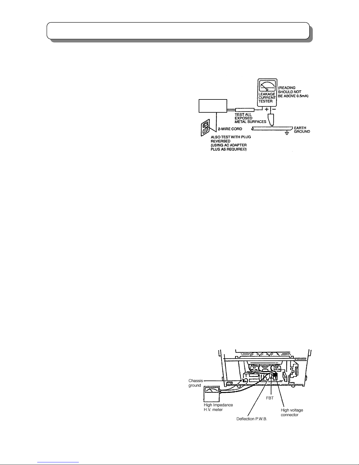
d) Leakage Current Hot Check - With the instrument
completely reassembled, plug the AC line cord
directly into a 220V outlet. (Do not use an isolation
transformer during this test.) Use a leakage current
tester or a metering system with the instrument AC
switch first in the ON position and then in the OFF
position, measure from a known earth ground (metal
water-pipe, conduit, etc.), to all exposed metal parts
of the instrument (antennas, handle bracket, metal
cabinet, screw heads, metallic overlays, control
shafts, etc.), especially any exposed metal parts that
offer an electrical return path to the chassis. Any
current measured must not exceed 0.7 milliamps.
Reverse the instrument power cord plug in the outlet
and repeat test. (See the following connection
diagram)
AC Leakage Test
ANY MEASUREMENTS NOT WITHIN THE LIMITS
SPECIFIED HEREIN INDICATE A POTENTIAL
SHOCK HAZARD THAT MUST BE ELIMINATED
BEFORE RETURNING THE INSTRUMENT TO THE
CUSTOMER OR BEFORE CONNECTING THE
ANTENNA OR ACCESSORIES
e) High Voltage - This receiver is provided with a hold
down clearly indicating that voltage has increased in
excess of a predetermined value. Comply with all
notes described in this Service Manual regarding
this hold down circuit when servicing, so that this
hold down circuit may correctly be operated.
f) Service Warning - With maximum contrast,
operating high voltage in this receiver is lower than
32kV. In case if any component having influence on
high voltage is replaced, confirm that the high
voltage with maximum contrast is lower than 32kV.
To measure H.V use a high impedance H.V. meter.
Connect (-) to chassis earth and (+) to the CRT
anode button. (See the following connection
diagram).
Note: Must turn power switch off before the connection
to the anode button is made.
(TH01)
INSTRUMENT
UNDER TEST
4
SAFETY PRECAUTIONS
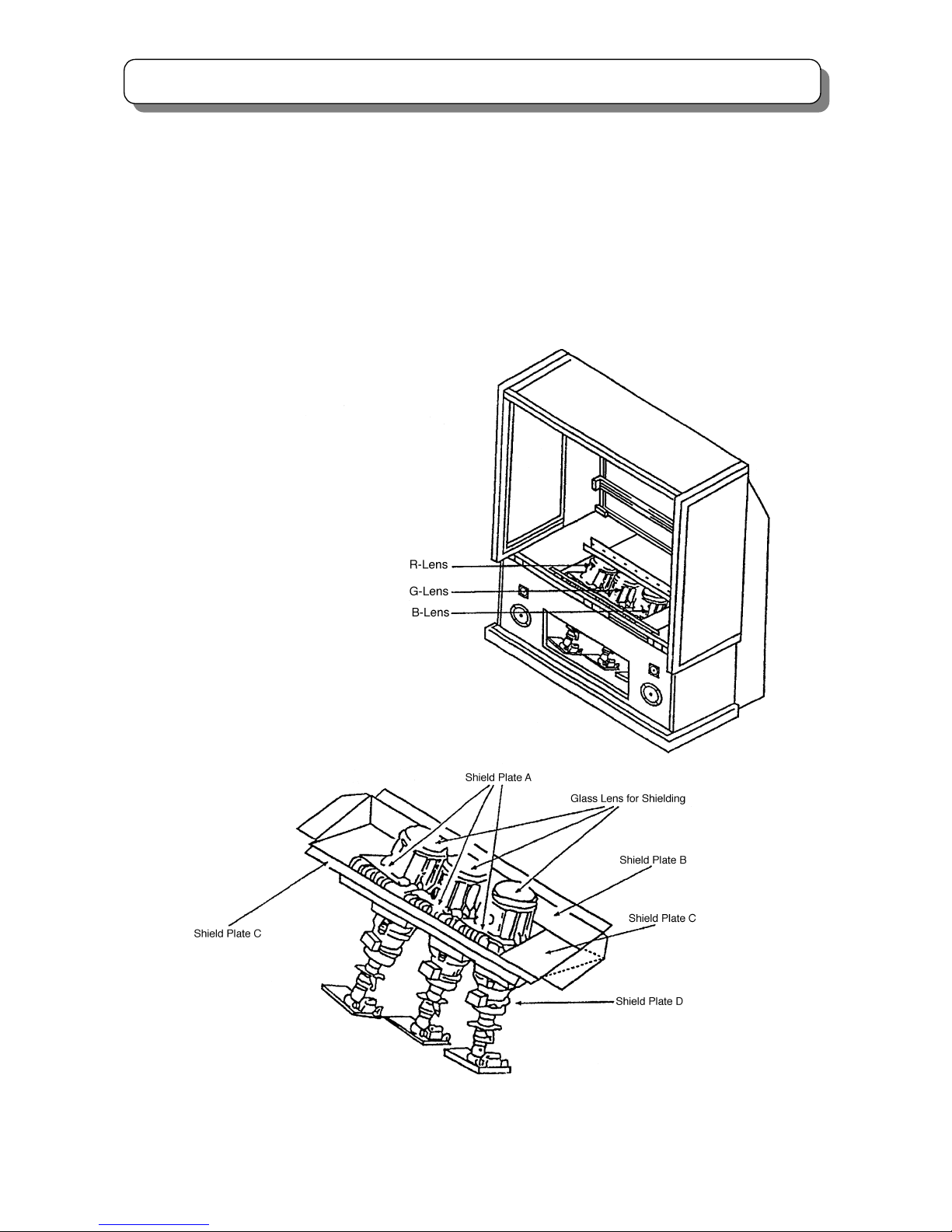
Fig. 1 X-ray shield plates
g) X-radiation (TUBE) -The primary source of
X-radiation in this receiver is the picture tube. The tube
utilized for the above mentioned function in this
chassis is specially constructed to limit X-radiation
emissions.
For continued X-radiation protection, the replacement
tube must be the same type as the original. HITACHI
approved type.
When troubleshooting and making test measurements
in a receiver with a problem of excessive high voltage,
avoid being unnecessarily close to the picture tube
and the high voltage component.
Do not operate the chassis longer than is necessary
to locate the cause of excessive voltage.
h) X-radiation Shield -This receiver is provided with
X-ray shield plates for protection against X-radiation.
Do not remove X-ray shield plates A, B, C, or D
shown in Fig.1 unnecessarily, when troubleshooting
and/or making test measurements.
To prevent X-radiation, after replacement of picture
tube and lens, confirm these components to be fixed
correctly to bracket and cabinet, and not to be taken
off easily.

5
SAFETY PRECAUTIONS
2. Read and comply with all caution and safety-related
notes on or inside the receiver cabinet, on the
receiver chassis, or on the picture tube.
3. Design Alteration Warning - Do not alter or add to
the mechanical or electrical design of this TV receiver.
Design alterations and additions, including but not
limited to circuit modifications and the addition of
items such as auxiliary audio and/or video output
connectors, might alter the safety characteristics of
this receiver and create a hazard to the user. Any
design alterations or additions may void the
manufacturer’s warranty and may make you, the
servicer, responsible for personal injury or property
damage resulting therefrom.
4. Picture Tube Implosion Protection Warning - The
picture tube in this receiver employs integral
implosion protection. For continued implosion
protection, replace the picture tube only with one of
the same type number. Do not remove, install, or
otherwise handle the picture tube in any manner
without first putting on shatterproof goggles equipped
with side shields. People not so equipped must be
kept safely away while picture tubes are handled.
Keep the picture tube away from your body. Do not
handle the picture tube by its neck.
5. Hot Chassis Warning
a) Some TV receiver chassis are electrically connected
directly to one conductor of the AC power cord and
may be safely serviced without an isolation
transformer only if the AC power plug is inserted so
that the chassis is connected to the ground side of the
AC power source. Confirm that the AC power plug is
inserted correctly with an AC voltmeter by measuring
between the chassis and a known earth ground. If a
voltage reading in excess of 1.0V is obtained, remove
and reinsert the AC power plug in the opposite polarity
and again measure the voltage potential between the
chassis and a known earth ground.
b) Some TV receiver chassis normally have 85V AC
(RMS) between chassis and earth ground regardless
of the AC plug polarity. These chassis can be safely
serviced only with an isolation transformer inserted in
the power line between the receiver and the AC power
source, for both personnel and test equipment
protection.
c) Some TV receiver chassis have a secondary ground
system in addition to the main chassis ground. This
secondary ground system is not isolated from the AC
power line. The two ground systems are electrically
separated by insulating material that must not be
defeated or altered.
6. Observe original lead dress. Take extra care to assure
correct lead dress (the AC supply, high voltage and
antenna wiring) in the following areas:
a) Near sharp edges
b) Near thermally hot parts
Be sure that leads and components do not touch
thermally hot parts. Always inspect in all areas for
pinched, out-of -plate, or frayed wiring; Do not
change spacing between components and the printed
circuit board; Check AC power cord for damage.
7. Components, parts, and/or wiring that appear to have
overheated or are otherwise damaged should be
replaced with components, parts or wiring that meet
original specifications. Additionally, determine the
cause of overheating and/or damage and, if
necessary, take corrective action to remove any
potential safety hazard.
8. PRODUCT SAFETY NOTICE - Many TV electrical
and mechanical parts have special safety-related
characteristics some of which are often not evident
from visual inspection, nor can the protection they
give necessarily be obtained by replacing them with
components rated for higher voltage, wattage, etc.
Parts that have special safety characteristics are
identified by a
! in the replacement parts list. Use of
substitute replacement that does not have the same
safety characteristics as the recommended
replacement part in the parts list might create shock,
fire, and/or other hazards. Product safety is under
review continuously and new instructions are issued
whenever appropriate. For the latest information,
always consult the appropriate current service
literature. A subscription to, or additional copies of
service literature may be obtained at a nominal
charge from manufacturer.
6
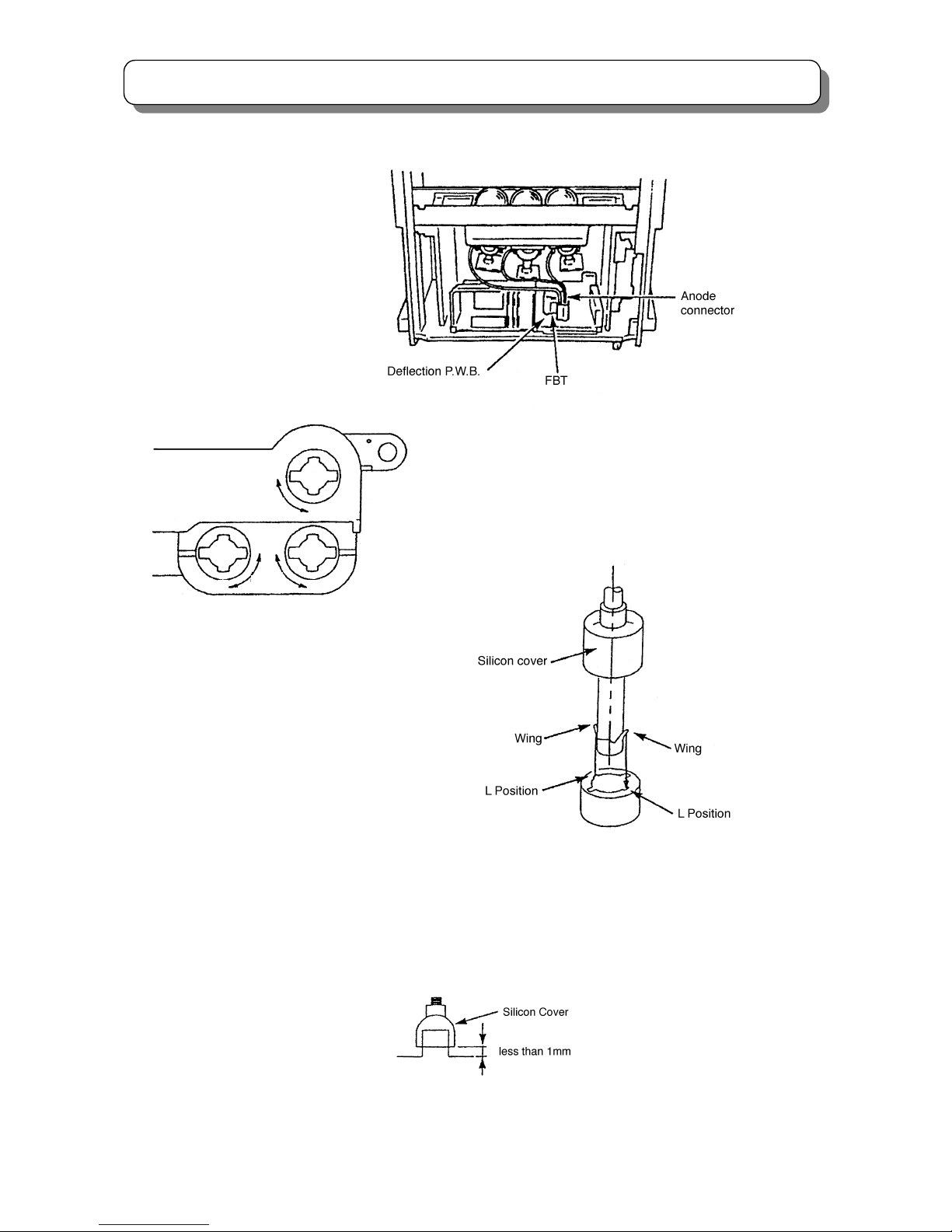
CAUTIONS WHEN CONNECTING/DISCONNECTING THE HV CONNECTOR
Perform the following when the
HV connector (anode connector)
is removed or inserted for PRT
replacement, etc.
During Insertion
1. Please refer to direction for insertion as shown in Fig. 4 (L position). Insert connector until “CLICK” sound is heard.
2. Make sure the connector is pressed right in, so that it has a good contact with the spring.
3. Confirm the contact by pulling the connector slightly. (Don’t pull hard because it may damage the connector).
4. Cover the high voltage output by carefully pushing silicon cover onto it. (Don’t turn the connector).
(REMARK)
1. Make sure the silicon cover is
covering the high voltage output.
During Removal
1. Roll out silicon cover from FBT’s contact area slowly.
2. While turning the connector about 90 degrees following the
arrow (from L position to O position), push the connecto
r
slightly towards the case. (Fig .3)
3. Remove the connector slowly by pulling it away from the
case.
Fig. 3 Remove the anode connector
Fig. 4 Insert the anode connector
O
O
L L
L
PUSH
PUSH
7
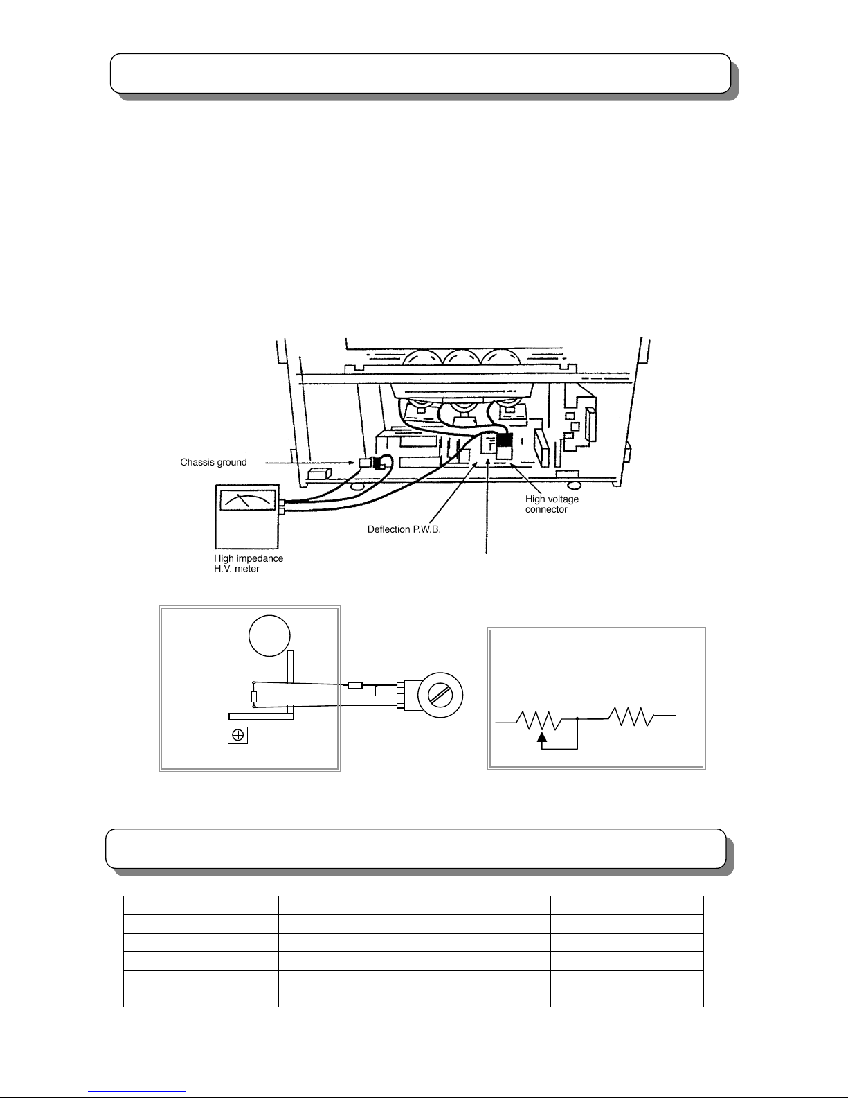
TECHNICAL CAUTIONS
High Voltage limiter circuit operation check
1. Turn off TV and delete resistor RH19 (82KΩ) in the Power/Deflection PWB, set 50KΩ VR fully clockwise(maximum
resistance).
2. Set the AC input to 220V AC and turn on TV.
3. Confirm test pattern on PRT is a usable picture, then slowly adjust 50KΩ VR until the picture disappears and TV
shuts down.
4. When the limiter circuit is operating properly, High Voltage will be less than 35.6kV(maximum brightness and
contrast).
5. Turn off TV immediately after checking High Voltage limiter circuit operation.
6.Unplug TV for one minute to reset shutdown circuit. Remove the jig A, and then add resistor RH19(82KΩ)to the PWB.
FBT
TH01
RH19
33 KΩ
50 KΩ VR
Fig.2 High Voltage limiter circuit operation check
POWER /
DEFLECTION PWB
FBT
33 KΩ
50 KΩ VR
Connect Jig A to PWB between RH19
RH17
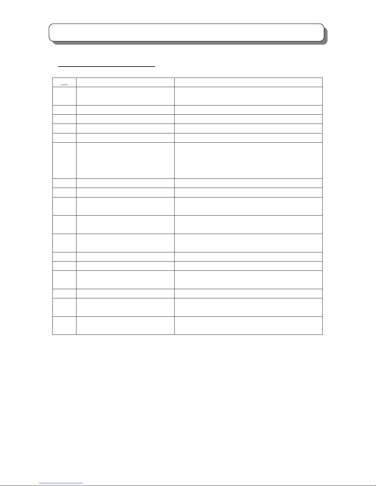
CIRCUIT PROTECTION
Fuse (or Device) Circuit Protected Physical Location
F901(T6.3AL/250V)
AC POWER CIRCUIIT Power Supply Unit
F902(T1AL/250V)
STAND BY CIRCUIT Power Supply Unit
F903(T3.15AL/250V)
SIGNAL POWER CIRCUIT Power Supply Unit
F904(2.2Ω/fuse)
SIGNAL POWER CIRCUIT Power Supply Unit
FP01(T3.15AL/250V)
PRIMARY POWER CIRCUIT Power / Deflection PWB
8
LEAD FREE SOLDERING GUIDE
● Lead free solder
With some exception, this product is going to use lead free solder (unleaded) to help preserve the
environment from the September of 2004. Please read these instructions before attempting any soldering
work.
Caution: Always wear safety glasses to prevent fumes or molten solder from getting into the eyes.
Lead free solder can splatter at high temperatures. (600ºC).
■ Lead free solder indicator
There is a F mark made behind the name of PWB or close to its on the printed circuit boards with lead free
solder.
■ Properties of lead free solder
The melting point of lead free solder is 40--50ºC higher than lead solder.
■ Servicing solder
Unleaded solder with an alloy composition of Sn-3.0Ag-0.5Cu is recommended. Although servicing with
leaded solder is possible, there are a few precautions that have to be taken. (Not taking these precautions
may cause the solder to not harden properly, and lead to consequent malfunctions.)
■ Precautions when using leaded solder
● Remove all lead free solder from soldered dots when replacing components.
● If leaded solder should be added to existing unleaded soldered dots , melt the leaded solder thoroughly
and mix it in the unleaded solder after the unleaded soldered dots have been completely melted. (It’s not
permitted to solder directly with soldering iron without solder)
■Servicing soldering iron
A soldering iron with a temperature setting capability (temperature control function) is recommended. The
melting point of unleaded soldering tin is higher than that of leaded ones. Use a soldering iron that maintains
a high stable temperature (large heat capacity) and allows temperature adjustment according to the parts
awaiting serviced to avoid poor servicing performance.
■ Recommended soldering iron
● Soldering iron with temperature control function (temperature range:320--450ºC)
Recommended temperature range per part:
PARTS Soldering iron temperature
Mounting (chips) on mounted PCB 320ºC±30ºC
Mounting (chips) on empty PCB 380ºC±30ºC
Chassis, metallic shield, etc. 420ºC±30ºC
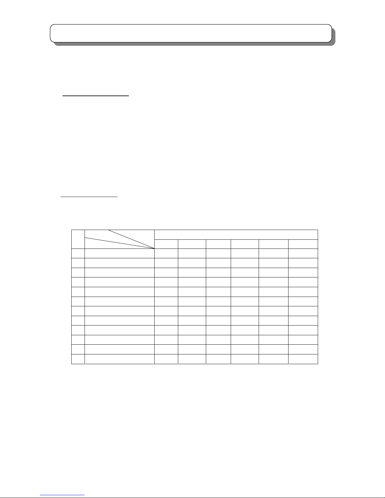
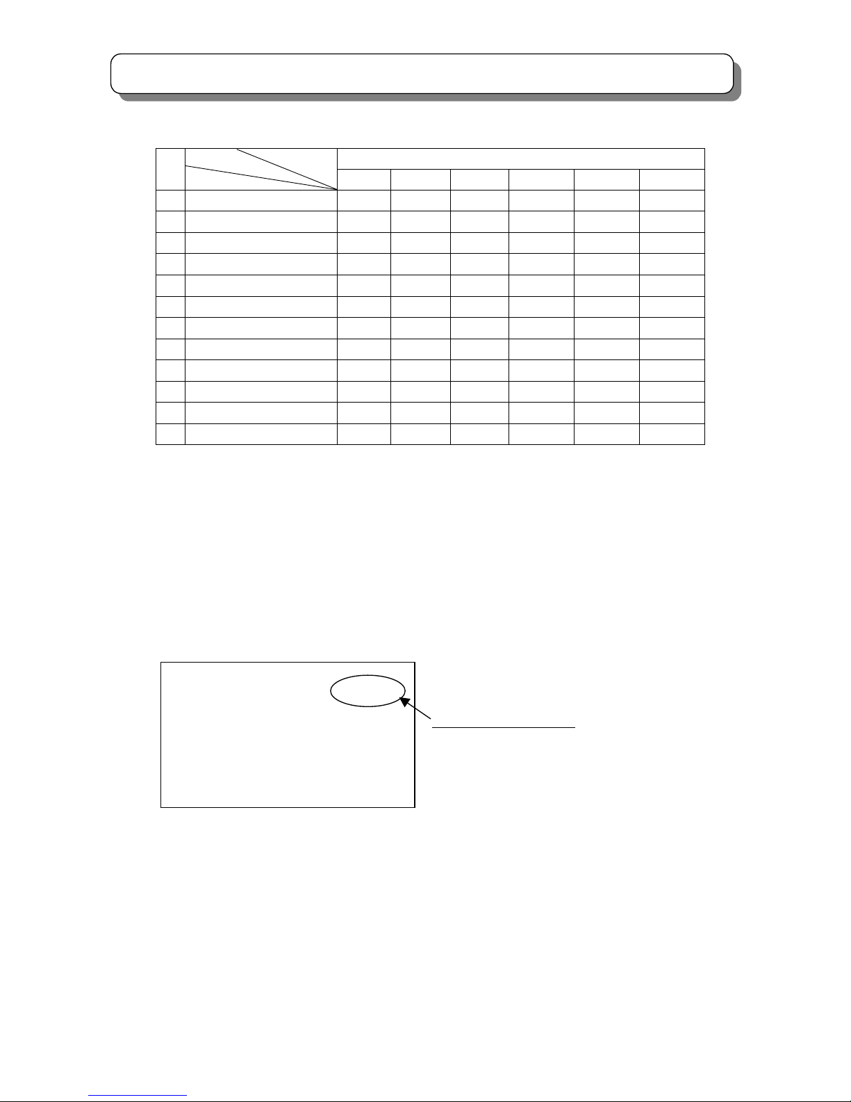
9
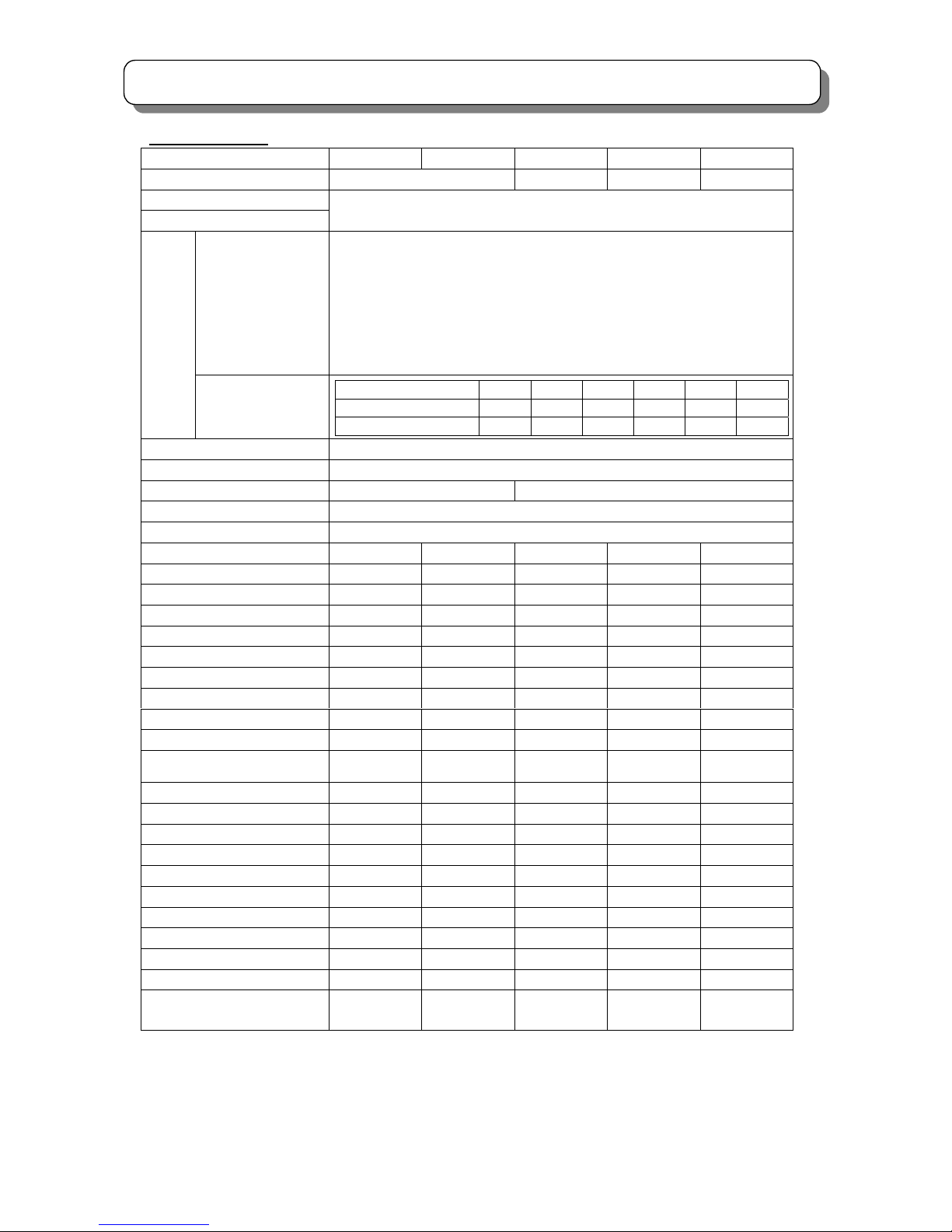
SPECIFICATIONS
Specifications
Model
C43-FL8000 C43-FD8000 C50-FD8000 C47-WD8000 C57-WD8000
Screen size 109cm 127cm 119cm 145cm
Power supply
Power consumption
Refer to the values as indicated on the rating label pasted at the back of the TV set.
PAL B.G/I/D.K
SECAM B.G/D.K
NTSC 50
M/NTSC
NTSC3.58-5.5/6.0/6.5
NTSC4.43-5.5/6.0/6.5
RF/VIDEO
PAL/SECAM 60
Reception
system
COMPONENT
Frequency range 44MHz-863 MHz
Antenna input impedance 75Ohm non balance type
Speaker Φ12×2 ,Φ5×2 Φ13×2 ,Φ5×2
Sound output 20W×2
Comb filter 3L(PAL)/3D(NTSC)
Digital convergence Yes Yes Yes Yes Yes
Magic focus No(manual) Yes Yes Yes Yes
Perfect v o l u m e Ye s Ye s Ye s Yes Ye s
NICAM/A2 Yes Ye s Ye s Ye s Ye s
BBE Yes Yes Yes Yes Yes
SRS Ye s Ye s Yes Yes Ye s
P i n P Yes Ye s Yes Yes Ye s
Tel e t ext No Yes Yes Yes Ye s
S-VIDEO INPUT 1(side),2(rear) 1(side),2(rear) 1(side),2(rear) 1(side),2(rear) 1(side),2(rear)
VIDEO INPUT 1(side),4(rear) 1(side),4(rear) 1(side),4(rear) 1(side),4(rear) 1(side),4(rear)
COMPONENT INPUT
(Y、P
B/CB、PR/CR)
2(rear) 2(rear) 2(rear) 2(rear) 2(rear)
HDMI INPUT
No
No No
1(rear) 1(rear)
BRIDGE MEDIA
No No No Ye s Yes
PC INPUT
No No No Ye s Yes
AUDIO INPUT 1(side),4(rear) 1(side),4(rear) 1(side),4(rear) 1(side),4(rear) 1(side),4(rear)
MONITOR OUT 1(rear) 1(rear) 1(rear) 1(rear) 1(rear)
HEADPHONE OUTPUT 1(side) 1(side) 1(side) 1(side) 1(side)
IR BLASTER OUT No 2(rear) 2(rear) 2(rear) 2(rear)
FIXED/VARIABLE AUDIO OUT 1(rear) 1(rear) 1(rear) 1(rear) 1(rear)
Shieldin g N o No Ye s Yes Yes
Weight 57Kg 57Kg 69Kg 68Kg 84.5Kg
Dimension (mm)
(width×height×depth)
969mm×1229mm×
456mm
969mm×1229mm
×456mm
1119mm×1362mm
×498mm
1121mm×1223mm
×485mm
1344mm×1412mm
×530mm
Note: Specifications may be subject to change without notice for improvement.
Total scan lines 1125i 750p 625p 625i 525p 525i
Active scan lines 1080i 720p 576p 576i 480p 480i
Vertical frequency(Hz)
50/60 60 50 50 60 60
10
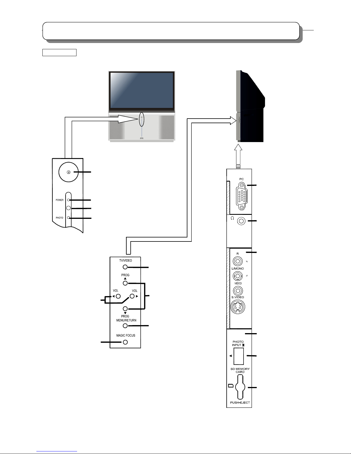
GENERAL INFOMATION
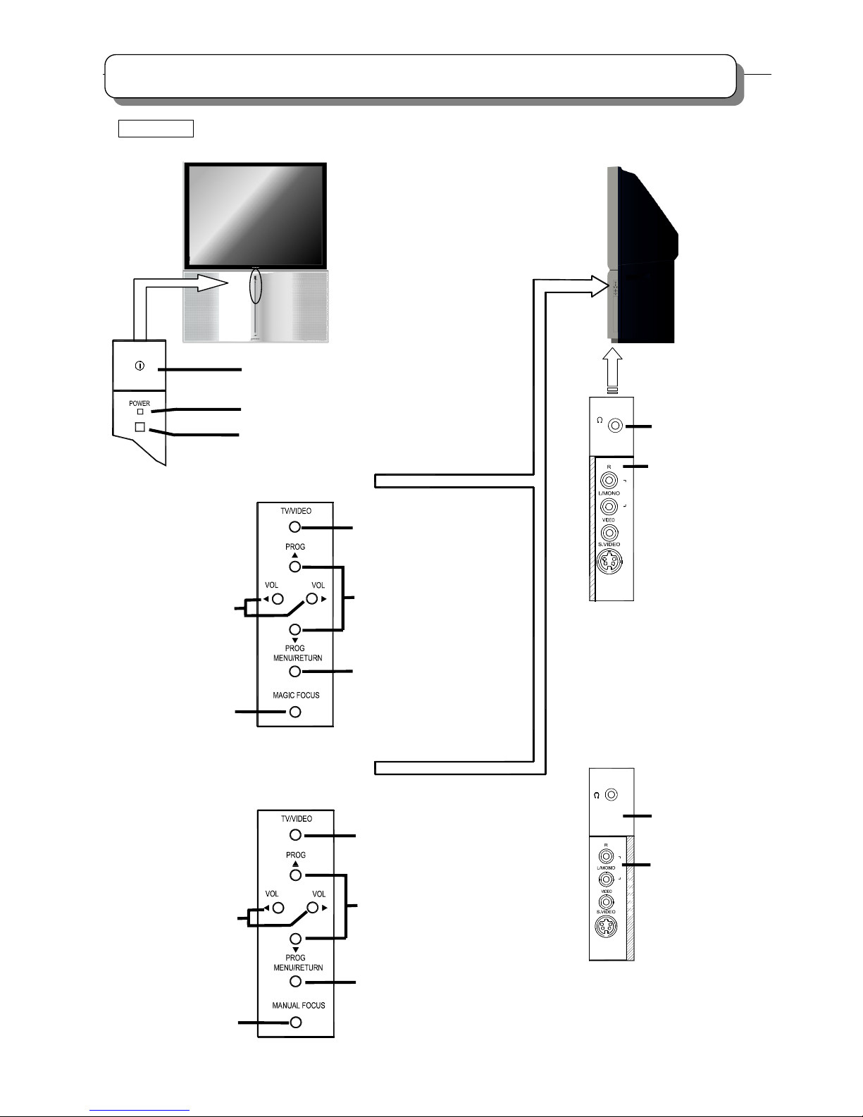
16:9 MODEL C47-WD8000 / C57-WD8000
Control panel and side panel
U
A
D
I
O
P
U
T
5
N
I
P
C
I
N
P
U
T
MENU/RETURN button
POWER button
POWER indicator
Remote control sensor
PROGRAM UP/DOWN buttons
(When the menu appears on
the screen, press PROG ▲/
PROG▼ buttons to select the
menu up and down.)
TV/VIDEO selector
BRIDGE MEDIA status indicator
HEADPHONE jack
Side panel input jacks
(For AV5 input)
PC INPUT terminal
VOLUME UP/DOWN
buttons (When the menu
appears on the screen,
press VOL◄ / VOL►
buttons to select the
menu left and right.)
MAGIC FOCUS button
BRIDGE MEDIA
INPUT terminals
USB slot
SD memory card slot
11
GENERAL INFOMATION
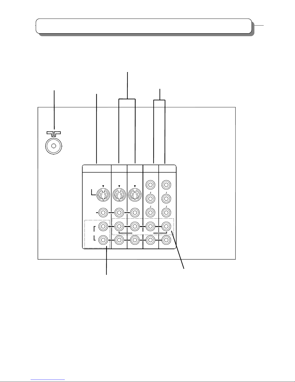
Rear panel
Fixed/Variable Audio output
terminals
A
ntenna terminal
Monitor output
terminals
A
udio/Video input terminals 3,4
A
udio/Video input & Component
input terminals 1,2
IR BLASTER output jacks
TV AS CENTER input jacks
HDMI
(High Definition Multimedia Interface)
12
GENERAL INFOMATION
4:3 MODEL C43-FD8000 / C50-FD8000 / C43-FL8000
Control panel and side panel
I
N
5
T
U
P
O
I
D
A
U
MENU/RETURN button
POWER button
POWER indicator
Remote control sensor
PROGRAM UP/DOWN
buttons (When the menu
appears on the screen,
press PROG ▲/ PROG▼
buttons to select the menu
up and down.)
TV/VIDEO selector
HEADPHONE jack
Side panel input jacks
(For AV5 input)
VOLUME UP/DOWN
buttons (When the
menu appears on
the screen, press
VOL◄/VOL►
buttons to select
the menu left and
right.)
MAGIC FOCUS
button
Function of keys
Function of keys
(C43-FD8000, C50-FD8000)
5
T
U
P
N
I
O
I
D
U
A
or
(C43-FD8000, C50-FD8000)
MENU/RETURN button
TV/VIDEO selector
MANUAL FOCUS
button
(C43-FL8000)
PROGRAM UP/DOWN
buttons (When the menu
appears on the screen,
press PROG ▲/ PROG▼
buttons to select the menu
up and down.)
HEADPHONE jack
Side panel input jacks
(For AV5 input)
(C43-FL8000)
VOLUME UP/DOWN
buttons (When the
menu appears on
the screen, press
VOL◄/VOL►
buttons to select
the menu left and
right.)
13
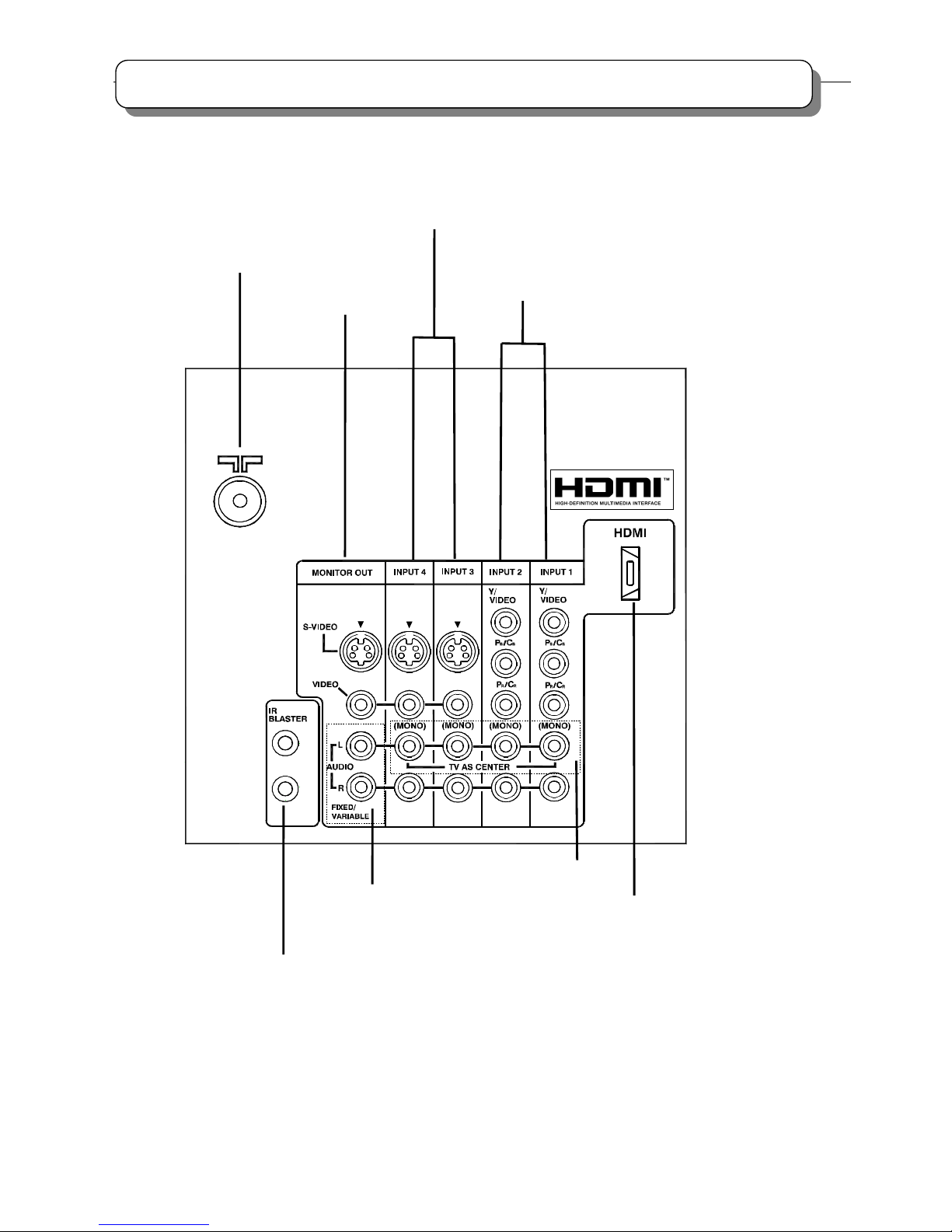
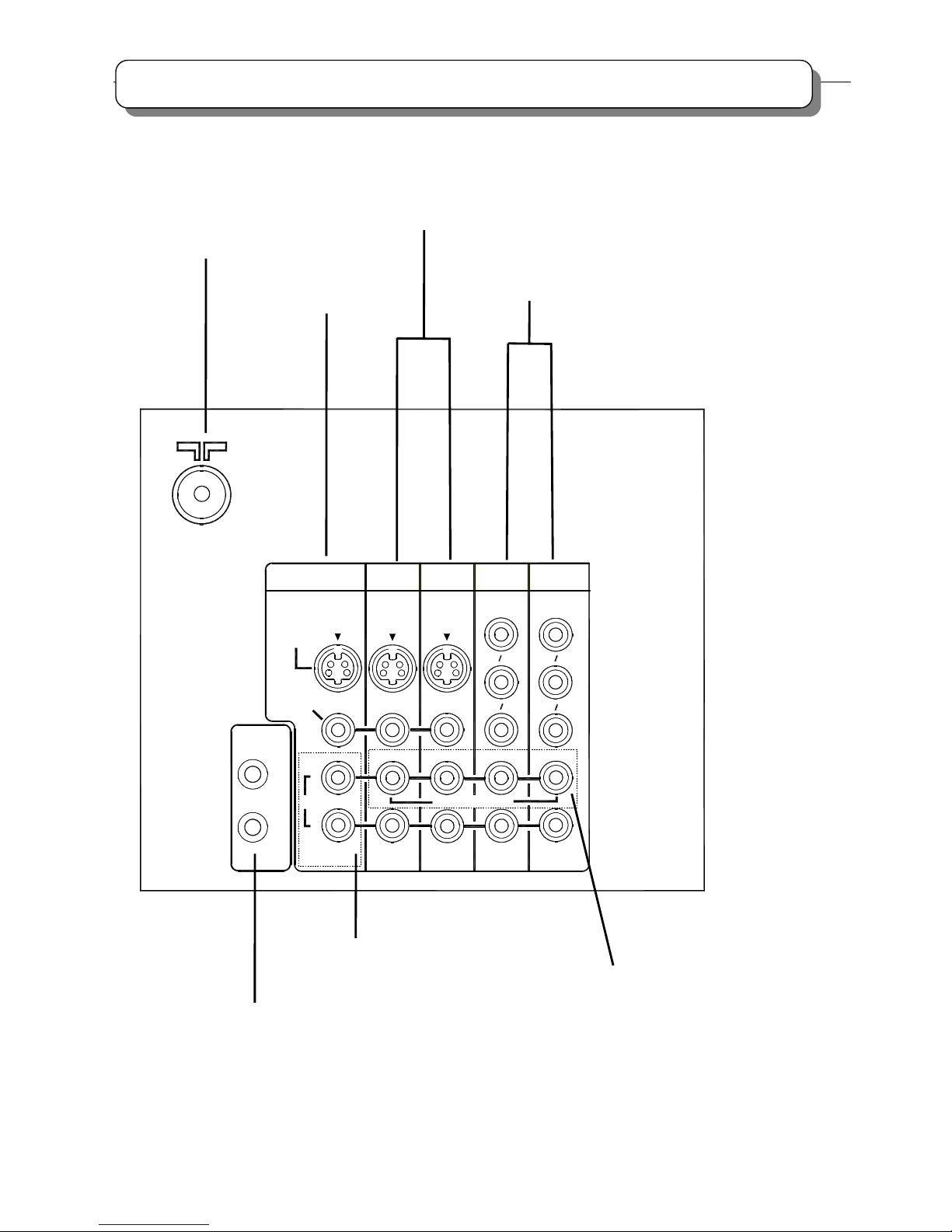
GENERAL INFOMATION
Rear panel
(The rear panel shown as below is designed for C43-FL8000 model.)
Fixed/Variable Audio output
terminals
A
ntenna terminal
Monitor output
terminals
A
udio/Video input terminals 3,4
A
udio/Video input & Component
input terminals 1,2
TV AS CENTER input jacks
L
R
VIDEO
MONITOR OUT
(MONO)
C
P
RR
C
P
BB
Y/
INPUT 4
INPUT 3
INPUT 1
INPUT 2
S-VIDEO
AUDIO
VARIABLE
FIXED/
VIDEO
C
P
RR
C
P
BB
Y/
VIDEO
TV AS CENTER
(MONO) (MONO) (MONO)
14
GENERAL INFOMATION
Rear panel
(The rear panel shown as below is designed for C43-FD8000 model and C50-FD8000 model.)
L
R
AUDIO
VARIABLE
FIXED/
BLASTER
IR
S-VIDEO
(MONO)
C
P
RR
C
P
BB
Y/
VIDEO
C
P
RR
C
P
BB
Y/
VIDEO
TV AS CENTER
(MONO)
(MONO) (MONO)
VIDEO
MONITOR OUT
INPUT 4
INPUT 3
INPUT 1
INPUT 2
Fixed/Variable Audio output
terminals
A
ntenna terminal
Monitor output
terminals
A
udio/Video input terminals 3,4
A
udio/Video input & Component
input terminals 1,2
IR BLASTER output jacks
TV AS CENTER input jacks
15
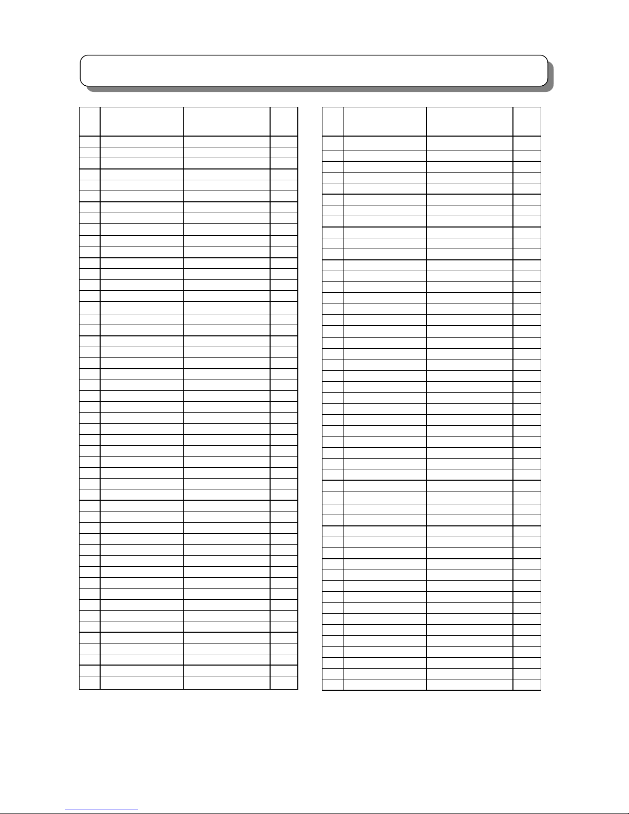
CPU(I001)PIN_FUNCTION
PIN PIN_NAME FUNCTION I/O
1 V HOLD1 Vertical Hold1 I
2 HLF Filter 1 I/O
3 IRB_RXD Communication RXD I/O
4 IRB_TXD Communication TXD I/O
5 HDMI CEC IN HDMI CEC Input I/O
6 IR_IN REMOTE IR Input I/O
7 M-S SYNC DET Sync Detect(M/S) I/O
8 BYTE Byte(GND) I
9 FLASH(CNVSS)
CNVSS(FOR PROGRAM)
I
10 SUB OSC IN SUB OSC Input I/O
11 SUB OSC OUT SUB OSC Output I/O
12 RESET Reset I
13 MAIN OSC OUT MAIN OSC Output O
14 VSS(ORIGIN) VSS(GND)
-
15 MAIN OSC IN MAIN OSC Input I
16 VCCI(+3.3V) VCCI(+3.3V)
-
17 OSC1-HLF OSC 1 I
18 OSC2 OSC 2 O
19 HDMI INI1 HDMI INI1 I/O
20 HDMI INI2 HDMI INI2 I/O
21 OSD BLK OSD BLK Output O
22 HALF TONE OSD Translucence O
23 HDMI DEMP2 HDMI DEMP2 I/O
24 HDMI CEC OUT HDMI CEC Output I/O
25 SD SELECT SYNC SELECT I/O
26 WDT CLOCK WDT CLOCK I/O
27 HDMI DEMP1 HDMI DEMP1 I/O
28 SCL2 IIC CLOCK 2 I/O
29 SCL1 IIC CLOCK 1 I/O
30 SDA1 IIC DATA 1 I/O
31 SDA2 IIC DATA 2 I/O
32 OSD_R OSD_R Output O
33 OSD_G OSD_G Output O
34 OSD_B OSD_B Output O
35 FLASH-TXD
TXD(FOR PROGRAM)
I/O
36 FLASH-RXD
RXD(FOR PROGRAM)
I/O
37 FLASH(SCLK)
SCLK(FOR PROGRAM)
I/O
38 FLASH(BUSY)
BUSY(FOR PROGRAM)
I/O
39 SCL3 IIC CLOCK 3 I/O
40 SDA3 IIC DATA 3 I/O
41 FLASH(EPM)
EPM(FOR PROGRAM)
I/O
42 DCU BUSY IN DCU BUSY Control I/O
43 DCU SIZE DCU SIZE Control I/O
44 SCL4 IIC CLOCK 4 I/O
45 SDA4 IIC DATA 4 I/O
46 FLASH (CE)
CE(FOR PROGRAM)
I/O
47 CUT OFF OUT CUT OFF Output I/O
48 HDMI HPD HDMI HPD I/O
49 V MUTE VIDEO MUTE I/O
50 HDMI RESET HDMI Reset I/O
PIN PIN_NAME FUNCTION I/O
51 FC DATA IN FC DATA Input I/O
52 FC DATA OUT FC DATA Output I/O
53 FC CLOCK CLOCK FOR FC I/O
54 FC ENABLE FC ENABLE Control I/O
55 SCL5 IIC CLOCK 5 I/O
56 SDA5 IIC DATA 5 I/O
57 MC LED MC LED I/O
58 POWER LED Power LED I/0
59 TV POWER Power ON/OFF Control I/O
60 IRB IR SELECT IR Select I/O
61 MC ENABLE MC MODE ENABLE I/O
62 OSD H SYNC IN OSD H SYNC Input I
63 MC WAKEUP OUT MC MODE CONTROL I/O
64 OSD V SYNC IN OSD V SYNC Input I
65 60Hz OUT 60Hz Output I/O
66 100Hz OUT 100Hz Output I/O
67 28KHz OUT 28KHz Control I/O
68 TEXT RESET TEXT RESET I/O
69 MSP RESET MSP RESET I/O
70 V SQUEEZE OUT Vertical Squeeze Output I/O
71 AUDIO MUTE AUDIO MUTE Output I/O
72 KEY OUT(2) KEY OUT(2) I/O
73 AV5 DET AV 5 Input Detect I/O
74 AV1 DET AV 1 Input Detect I/O
75 KEY OUT(1) KEY OUT(1) I/O
76 NC I/O
77 BM MUTE BM Mute I/O
78 HDMI SPDIF SEL HDMI SPDIF Select I/O
79 LIGHT OUT LIGHT ON/OFF I/O
80 HP DET HP DETECT I/O
81 KEY IN(2) KEY IN(2) I/O
82 KEY IN(1) KEY IN(1) I/O
83 NC I/O
84 IF SYS1(S) OUT SUB IF SYS1(S) I/O
85 IF SYS1(M) OUT MAIN IF SYS1(M) I/O
86 IF SYS2(M) OUT MAIN IF SYS2(M) I/O
87 IF SYS2(S) OUT SUB IF SYS2(S) I/O
88 IRB RESET IR BLASTER Reset I/O
89 AGC IN (S) SUB AGC Input I/O
90 AGC IN (M) MAIN AGC Input I/O
91 DIP DETECT DIP Detect I/O
92 SUB AFC IN SUB AFC Input I/O
93 MAIN AFC IN MAIN AFC Input I/O
94 AD KEY IN AD_KEY IN I/O
95 V HOLD2 Vertical Hold2 I/O
96 HLF2 Filter 2 I/O
97 SUB CCD IN SUB CCD Input I
98 TVSETB GND I
99 VCCE VCCE(5V)
-
100 MAIN CCD IN MAIN CCD Input I
16
TROUBLE SHOOTING
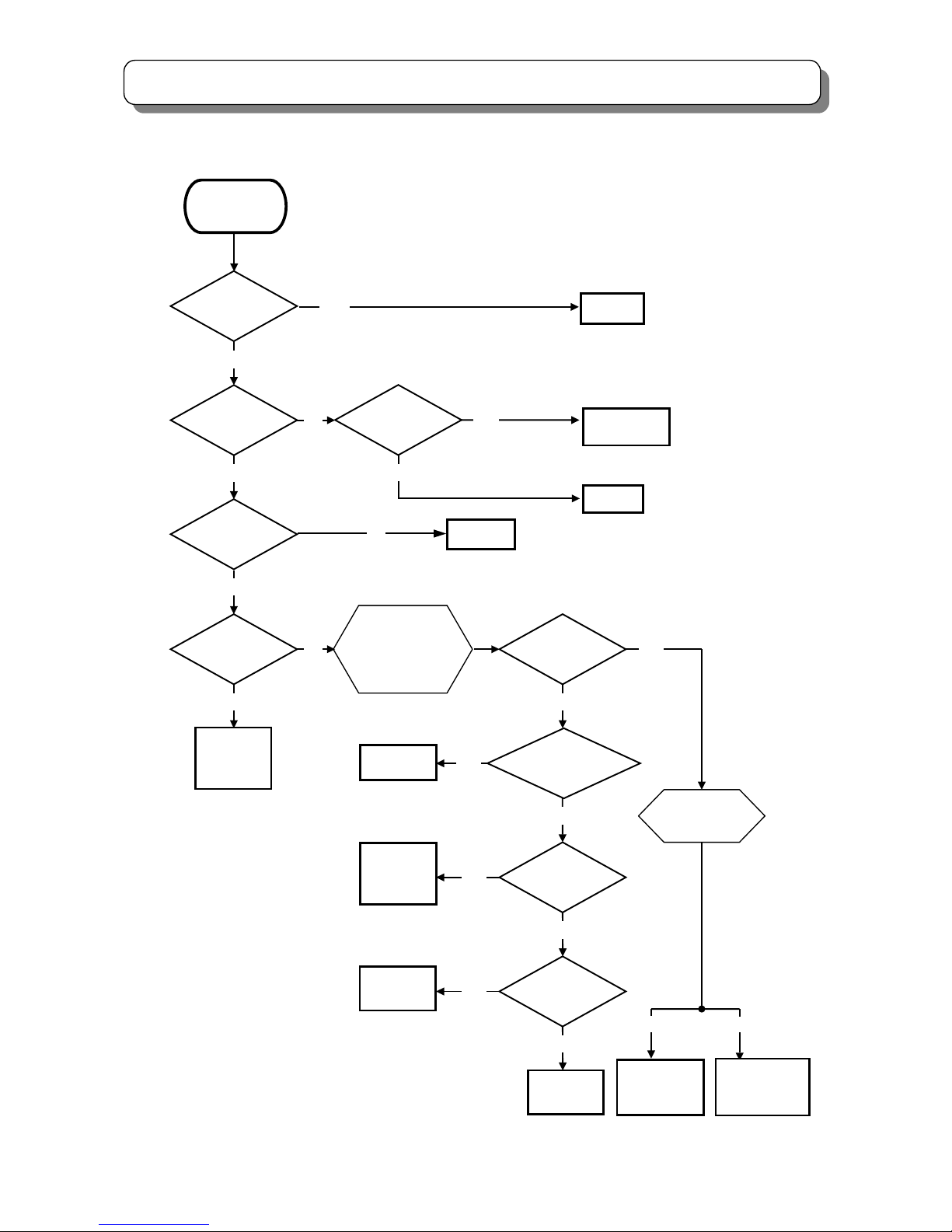
Is click sound
of Relay heard?
Are 2 Green LEDs
turned OFF at the
same time?
I901,I904,
F902 etc
Check
No
Raste
r
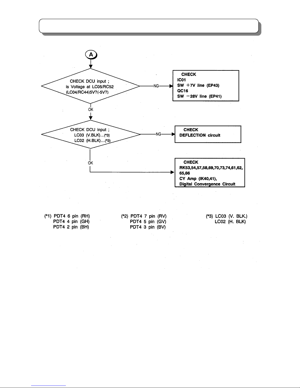
Is Voltage at
of D993(K)
5.8V
Has Fuse FP01
blown?
F903,I902,
I941 etc
YES
YES
YES YES
NO
Is base Voltage
of Q709 normal?
Does raste
r
appear with (7) and (17)
of PPT3 shorted?
Are Voltages
At both ends of T702
(primary side)
normal?
PDT2 pin(9)
-H out,
PDT3 pin(3)
-DEF 10.5V
etc.
T702, R748,
R730,etc.
Q777, QH01,
T701, TH01
etc.
NO
NO
YES
YES
Is Voltage
at pin(6) of PPT3
(R947) 2.5V?
Check
Check
Check
Check
Check
IP01,TP01,
DP05,DP02
etc.
Replace FP01
Check
Q944,
S903
YES
Check
uCOM
Power control
YES
Check
Find LED(s) that is
Turned dark or OFF
Earlier than the other.
(1) TROUBLE SHOOTING for POWER CIRCUIT
No raster and no power (How to check LED’s Diagnosis)
(Sig
nal Power PWB)
(Sig
nal Power PWB)
(Sig
nal Power PWB
)
(Pow Def PWB)
Check
(
Pow Def PWB)
(
Pow Def PWB
)
(Sig
nal Power PWB)
(Sig
nal Power PWB)
(Pow Def PWB)
Is Voltage
at D949(K) 5V?
SW+28/-28V line
EP40, EP41,
DP40, DP42,etc.
SW+115V line
EP45, DP46,
Q777,QH01,
Q701,TH01,
T701 etc.
Q980,Q981,
Q901 etc
(Pow Def PWB)
NO
NO
NO
YES
NO
NO
NO
1.Turn OFF
the power SW.
2.Wait for 3 seconds.
3.Turn ON again after
several seconds, and
observe green LEDs
carefully.
DP59
DP48
17
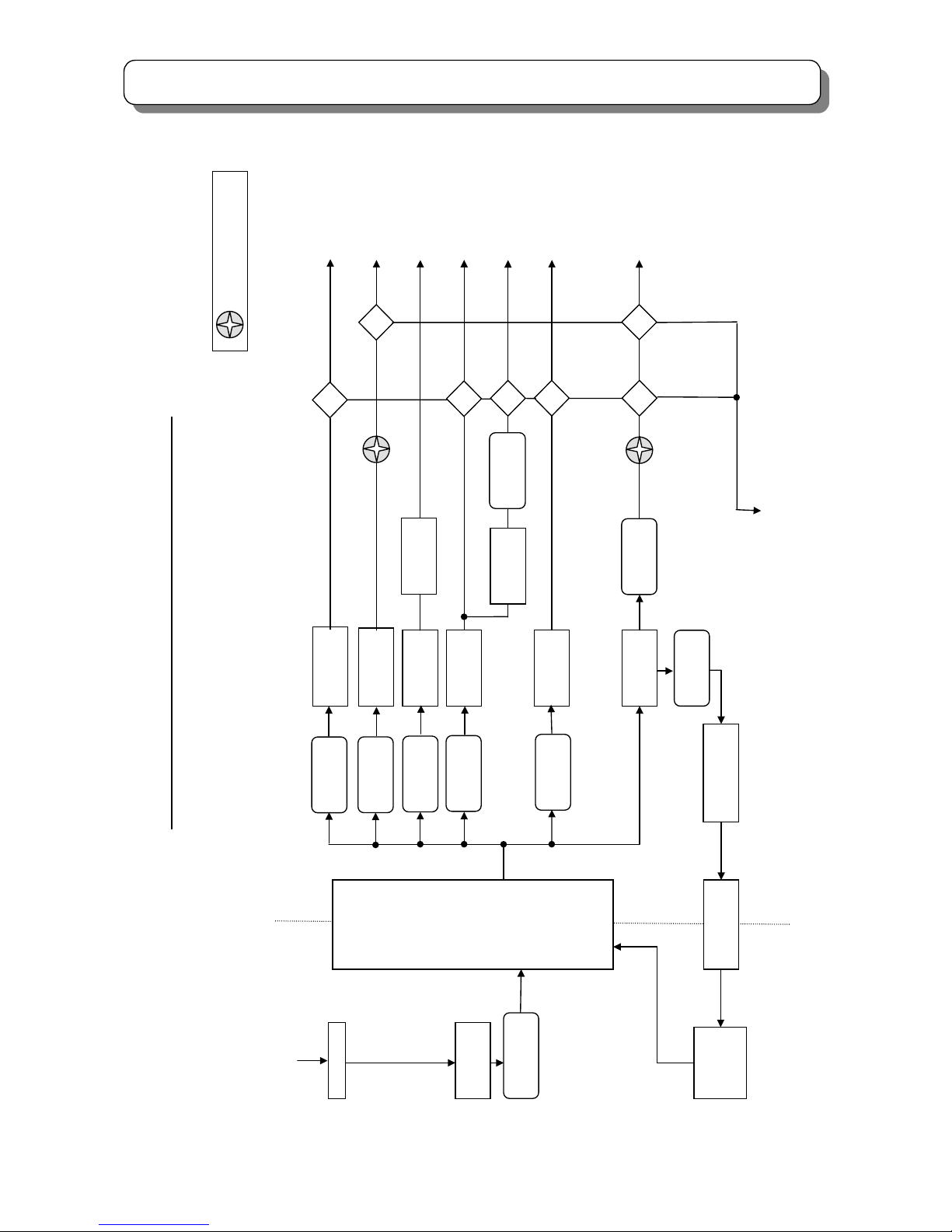
TROUBLE SHOOTING
(2) PROPTECTION CIRCUIT BLOCK DIAGRAM
DP59:+115V
Switching
Transformer
TP01
LIVE
COLD
Feed Back
IP02
Rectifier
+28V:DP40
Rectifier
+12V:DP43
Rectifier
+115V:DP46
Protecto
r
EP45:3
Rectifier
-24V:DP42
DP48:+28V
DP58:>133
QP41:>1.8A
Q
ZD
DP60:>32V
ZD
ZD
Voltage Control
+115V:IP40
Short CCT.
Detecto
r
Over Voltage
Detecto
r
= GREEN LED
DP5M Protection Circuit Block Daigram (Deflection Power Supply)
Switching
Control
IP01
AC Input
Rectifier
DP01
Fuse
FP01:T3.15A
Deflection:
DEF+115V
Conver / DCU:
DEF-28V
Conver / Vert:
DEF+28V
Video:
DEF+220V
DCU:
DEF+7.5V
Rectifier
+7V:DP44
Regulator
+6.3V:QP40
Heater:
DEF+6.3V
Protecto
r
EP47:2
From Power P.W.B
Protecto
r
EP44:4
Protecto
r
EP41:10
Protecto
r
EP43:5
Protecto
r
EP42:3
Protecto
r
EP40:10
Rectifier
+220V:DP45
D
DP63:<5V
Regulator
+10.5V:IP41
D
D
DP65:
<
5V
DP62:<5V
DP60:>-20V
Protecto
r
EP46:0.5
DEF CCT.
Protect
18
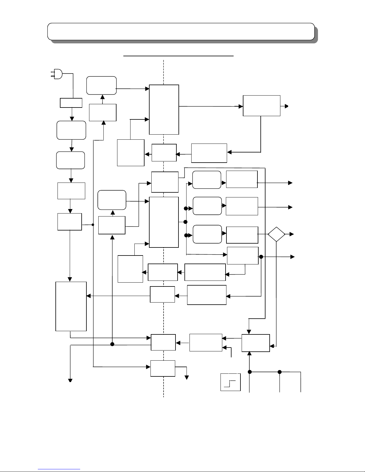
TROUBLE SHOOTING
DP5M Protection Circuit Block Daigram
Audio:
+38.5V
Signal:
SIG+10.5V
>AC300V
A
C Input
Fuse
F901:T6.3
Varistor
X901:681
Line Filter
L901
Line Filter
L902
Temperature
Limited
Fusing
Resistor
F904
Fuse
F902:T1A
Rectifier
D901
Switching
Control
I901
Switching
Transformer
T901
Feed Back
I904
AC-OVP
I905
Switching
Transformer
T902
Fuse
F903:T3.15
Rectifier
D902
Switching
Control
I902
Feed Back
I906
Protector
E940:7
Protector
E942:2
Protector
E941:5
Rectifier
+38.5V:D960
Rectifier
+35V:D961
Rectifier
+10.5V:D954
Voltage Control
+5.2V:D962
Voltage Control
+5.6V:I941
Rectifier
+5.6V:D955
ZD
Rush R On/Off
Switch:Q942
Protect
On/Off
RELAY
S901
DEF CCT
Protect
SIG CCT
Protect
CPT CCT
Protect
Over Voltage
Detecto
r
Signal:
SIG+5.6V
Signal:
SBY+5.2V
D988:>14V
Rectifier
+5.2V:D949
Power On/Off
Switch:Q944
RELAY
S903
AC Clock
I903
AC Clock
50Hz
COLD
LIVE
AC Plug
Power_1
On/Off
On
Off
(TV)
To Deflection
Power Suppl
y
19
TROUBLE SHOOTING
)
20
TROUBLE SHOOTING
21
TROUBLE SHOOTING
22
TROUBLE SHOOTING
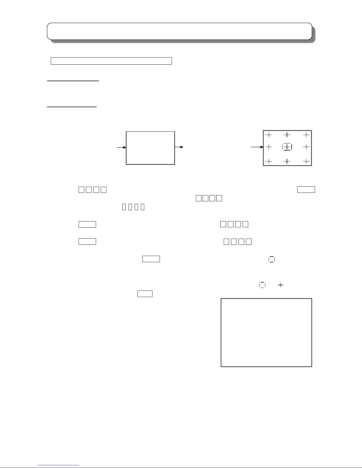
How to Adjust 9 Point Manual Convergence
Adjustment Preparation
Receive RF or Video signal.
Adjustment Procedure
Press and hold the MAGIC/MANUAL FOCUS button for more than 3 seconds to enter the MANUAL CONVERGENCE
mode.
(Note: If you press the MANUAL FOCUS button on the side panel of C43-FL8000 model, the TV will enter the MANUAL
CONVERGENCE mode directly.)
(1) Press the ▲ ▼ ◄ ► cursor buttons to move the selection box to select the adjustment point. Press the ENTER
button to change the color of the selection box to red. Press the ▲ ▼ ◄ ► cursor buttons to adjust red convergence.
Note: Press the number buttons (2, 5, 4, 6) can also move the selection box to select the adjustment point, and then to
adjust red convergence directly.
(2) Press the ENTER button to change the selection box to blue. Press the ▲ ▼ ◄ ► cursor buttons to adjust blue
convergence.
(3) Press the ENTER button to change the selection box to white. Press the ▲ ▼ ◄ ► cursor buttons to move the
selection box to select another adjustment point, then perform (1)~(2) to adjust.
Notes: 1. During the adjustment, press the ENTER button frequently to return to the moving mode ( is shown in white,
which means the selection box is in the moving mode.) and affirm convergence of the selection box so as to get
the best convergence.
2. If you cannot insure perfect alignment, please try to get balance in alignment between and .
(4) When adjustment is done, press the MENU button and the following screen will display as below. Press the number
keys to perform the following procedure.
[0]: To cancel the adjusted data and exit from adjustment mode.
[1]: To save the adjusted data and exit from adjustment mode.
[2]: To return to manual convergence mode.
[3]: To recall the adjusted data from previous auto convergence
and return to manual convergence mode.
Notes:
1) During the adjustment, you are suggested to adjust again and again, and confirm
the alignment of the selection box in the moving mode.
2) If there is no operation for 3 minutes from the remote control unit, the TV will exit from MANUAL CONVERGENCE
mode.
Release the MAGIC
FOCUS button.
Press and hold the MAGIC
FOCUS button more than
3 seconds.
MANUAL FOCUS
PLEASE
ENTER NUMBER
CANCEL :[ 0 ]
DONE :[ 1 ]
BACK :[ 2 ]
RESET :[ 3 ]
23
TROUBLE SHOOTING
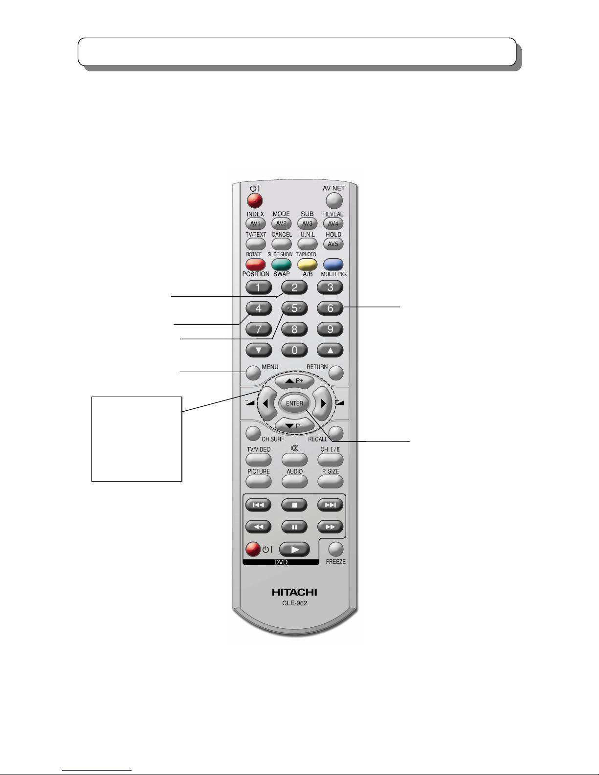
9 Point Manual Adjustment remote control
CURSOR LEFT
CURSOR DOWN
MENU
CURSOR RIGHT
CHANGE COLOR
(
Red & Blue)
ADJUSTMENT
[▲]:UP
[▼]:DOWN
[◄]:LEFT
[►]:RIGHT
CURSOR UP
24
TROUBLE SHOOTING
Trouble Shooting Guide for DP5M
No
Changed Parts Adjustment necessary(refer to page 25)
1 Signal PWB
No. 1.1/1.2/2.2/2.5/2.6/2.7/2.8/2.9/2.14/2.16/2.17/2.18/2.19/
2.20
2 Tuner (Main/Sub) No adjustment necessary
3 Microprocessor (I001) No adjustment necessary
4 FC unit No adjustment necessary
5 Sub signal PWB No adjustment necessary
6
Audio control / amplifier,NICAM/A2
I305(MSP3415G)
IA02(TA8258H)
IA01 (NJW1177V)
No adjustment necessary
7 EEPROM (I002) No. 1.1/1.2/2.6/2.7/2.8/2.9/2.14/2.16/2.17/2.18/2.19/2.20
8 Video chroma IC IV01,IW03 No. 2.19
9
Deflection Control/RGB IC
IX01
No. 2.14.2/2.16/2.17
10
Power / Deflection PWB
Sub Deflection PWB
No. 2.1/2.5/2.6/2.7/2.8/2.9/2.12/2.13/2.14/2.15/2.20
11
DCU circuit
IS06 / IT01 / IS01 / IS03
No. 2.2/2.5/2.14/2.20
12 Sub Signal PWB; Power PWB No adjustment necessary
13 Sensor PWB, Sensor No. 2.14/2.20
14 PRT tube
No. 1.3/2.1/2.3/2.4/2.5/2.6/2.7/2.8/2.9/2.10/2.11/2.12/2.13/
2.14/2.15/2.16/2.17/2.20
15 CPT PWB No. 2.1/2.12/2.13/2.14/2.15/2.16/2.17/2.20
16 DY
No. 1.3/2.3/2.4/2.5/2.6/2.7/2.8/2.9/2.10/2.12/2.13/2.14/2.15/
2.20
17
Deflection Control IC
IH01 (M62501P), FBT (TH01)
High voltage adjustment

25
SERVICE ADJUSTMENTS
SERVICE ADJUSTMENT ITEMS:
1.1 MEMORY INITIALIZE ……………………………………………………………………………………. 26
1.2 MODEL SETUP …………………………………………………………………………………………... 26
1.3 PREHEAT RUN CONDITION …………………………………………………………………………… 28
2.1 CUT OFF ADJUSTMENT ……………………………………………………………………………….. 28
2.2 DCU PHASE DATA SETTING ………………………………………………………………………….. 29
2.3 RASTER TILT ADJUSTMENT ………………………………………………………………………….. 30
2.4 BEAM ALIGNMENT ……………………………………………………………………………………… 32
2.5 RASTER POSITION ADJUSTMENT …………………………………………………………………... 33
2.6 SIDE PIN DISTORTION ADJUSTMENT ………………………………………………………………. 34
2.7 VERTICAL SIZE ADJUSTMENT ……………………………………………………………………….. 35
2.8 HORIZONTAL SIZE ADJUSTMENT …………………………………………………………………… 36
2.9 TRAPEZOID DISTORTION ADJUSTMENT ………………………………………………………….. 38
2.10 BEAM FORM ADJUSTMENT ………………………………………………………………………….. 39
2.11 LENS FOCUS ADJUSTMENT ………………………………………………………………………….. 40
2.12 STATIC FOCUS ADJUSTMENT ……………………………………………………………………….. 44
2.13 DYNAMIC FOCUS CHECK …………………………………………………………………………….. 45
2.14 DIGITAL CONVERGENCE ADJUSTMENT …………………………………………………………… 46
2.15 BLUE DEFOCUS ADJSUTMENT ……………………………………………………………………… 65
2.16 WHITE BALANCE ADJUSTMENT …………………………………………………………………….. 66
2.17 SUB BRIGHTNESS ADJUSTMENT …………………………………………………………………… 68
2.18 SUB PICTURE ADJUSTMENT …………………………………………………………………………. 69
2.19 TINT ADJUSTMENT …………………………………………………………………………………….. 70
2.20 MAGIC FOCUS INITIALIZE …………………………………………………………………………….. 71
3.1 PRT CABINET LOCATION ……………………………………………………………………………… 73
3.2 FOCUS PACK …………………………………………………………………………………………….. 73
3.3 MAIN P.W.B ……………………………………………………………………………………………….. 74
26
SERVICE ADJUSTMENTS
Before performing SERVICE ADJUSTMENTS★ ,please refer to the “TROUBLE SHOOTING”。
1.1 Memory initialize
When replacing signal P.W.B or EEPROM(I004), it requires perform Memory Initialize operation.
Adjustment Procedure
(1)Link the PRST① and PRST② for longer than 3 seconds.
(Please refer to page 74.)
(2)Wait until the OSD “1” is displayed (It takes several 10 seconds.) , this means initialization is
completed and each settings become factory preset condition.
Do not unplug the outlet or perform any key operation until the initialization is completed.
1.2 Model Setup
Adjustment Procedure
(1) Set following items in service menu according to respective model.
[4:3 Model]
4:3
No.
FD8000 FL8000
1 Model Select1:ASPECT
0 0
2 Model Select2:DESTINATION
1 1
3 Model Select3:LIGHT
1 0
4 Model Select4:MULTI_PICTURE
1 1
5 Model Select5:COLOR_MANAGER
1 1
6 Model Select6:PC
0 0
7 Model Select7:IR_BLASTER
1 0
8 Model Select8:PHOTO
0 0
9 Model Select9:TEXT
2 0
10 Model Select10:HDMI
0 0
11 Model Select11:SUB-Y/C
1 1
12 Model Select12:SRS
1 1
Models
Value
Items
27
SERVICE ADJUSTMENTS
[16:9 Model]
(2) After set the Items according to the above tables.
(a) Select item No.837(INIT3) in service menu and press and hold the [recall] key on the remote handset until the
OSD background changes to yellow. (It takes about 3 seconds.)
(b) Wait until the OSD background color becomes normal (It takes several 10 seconds.) , this means initialization
is completed and each settings become preset condition according to the model .
Do not unplug the outlet or perform any key operation until the initialization is completed.
(3) Check the setting state displayed on the upper right of the service menu.
V100-FFFF FC100-FFFF MC100 001111110011
No. Data
0: 0
1: 0
2: 0
3: 1
The state of Model Select setting
・From the left to the 1st figure:The state of Model Select1
……
・From the left to the 12th figure:The state of Model Select12
16:9
No.
WD8000
1 Model Select1:ASPECT 1
2 Model Select2:DESTINATION 1
3 Model Select3:LIGHT 1
4 Model Select4:MULTI_PICTURE 1
5 Model Select5:COLOR_MANAGER 1
6 Model Select6:PC 1
7 Model Select7:IR_BLASTER 1
8 Model Select8:PHOTO 1
9 Model Select9:TEXT 2
10 Model Select10:HDMI 1
11 Model Select11:SUB-Y/C 1
12 Model Select12:SRS 1
Models
Val ue
Items
28
SERVICE ADJUSTMENTS
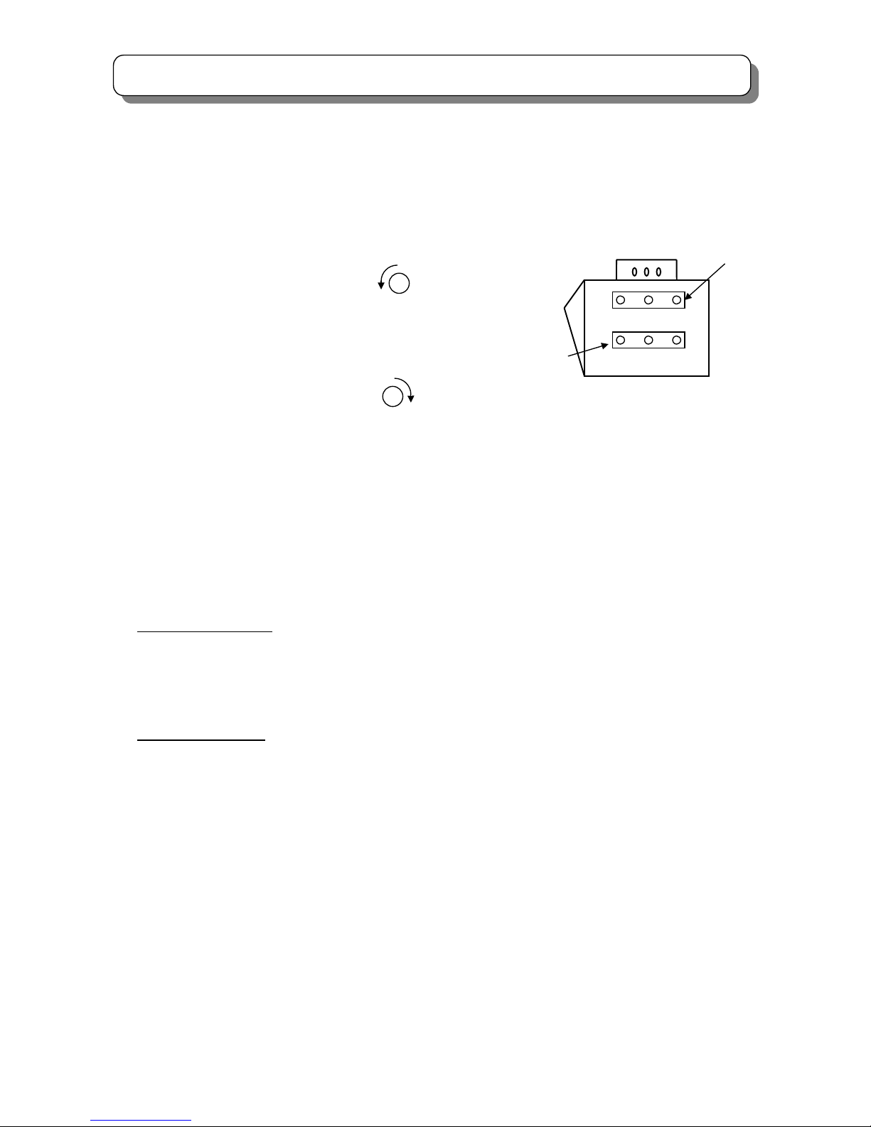
1.3 PREHEAT RUN CONDITION
* Preset each VR as in the following figure before PREHEAT RUN.
(1) SCREEN VR ON FOCUS PACK.
<PRESET> Turn counterclockwise to the end.
(2) STATIC FOCUS VR ON FOCUS PACK.
<PRESET>Turn clockwise to the end.
2.1 CUT OFF ADJUSTMENT
Adjustment preparation
(1) Preheat run should be finished.
(2) Confirm item No.54(R cut off), 55(G cut off) and 56 (B cut off) are set to 127 in service menu.
(3) Confirm item No.52(R DRV) and No. 53(G DRV) are set to 63 in service menu.
Adjustment procedure
(1) Select item No. 20 in service menu by using the remote controller.
Press [►] key to enter CUT OFF adjustment mode.
(2) Screen VR (R, G and B) should be turned clockwise gradually and set the condition that the each horizontal
line is just beginning to appear.
(3) Press [◄] key to return normal mode.
Screen VR
Focus VR
R G B
R G B
Screen VR
Static Focus VR
<Focus Pack>
29
SERVICE ADJUSTMENTS
2.2 DCU PHASE DATA SETTING
Adjustment preparation
(1) Cut off adjustment should be finished.
Adjustment procedure
(1) Receive PAL signal (RF or VIDEO) and set to 100Hz mode. (User MENU
FUNCTION \ SCAN MODE
\ 100Hz) Contrast should be set center and other control be set normal.
(2) Push the “SERVICE ONLY” switch on the SIGNAL P.W.B. to enter the adjustment mode of the digital
convergence unit.
(3) Phase set.
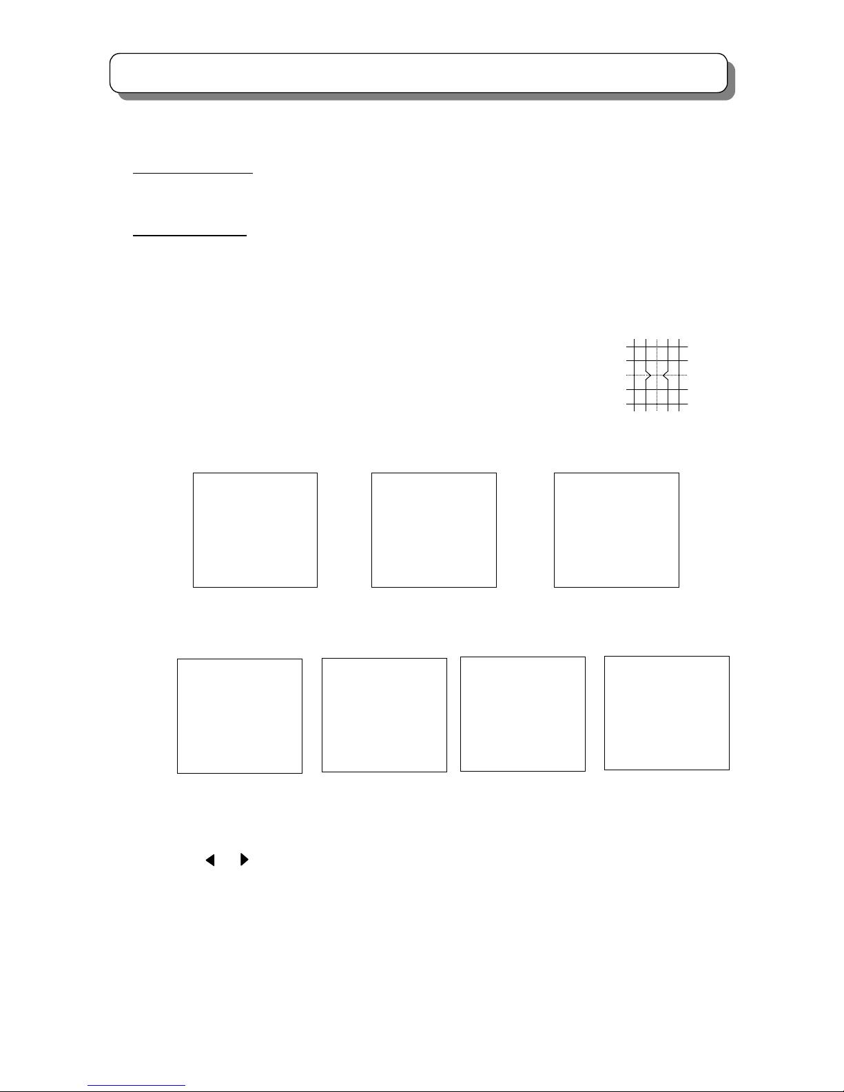
(3-1) Press the [REVEAL] key on R/C to display the green cross-hatch pattern.
(3-2) Press the [CH Ⅰ/Ⅱ] key to recall the phase DATA on screen.
【4:3】
【16:9】
(3-3) If phase data is not the same as above, change the DATA by using the following R/C keys.
Press [4] or [6] key to adjust the PH-H
Press [2] or [5] key to adjust the PH-V
Press [ ] or [ ] key to adjust the CR-H
Press [▲] or [▼] key to adjust the CR-V
(3-4) Press the [REVEAL] key to exit from phase mode.
(3-5) Press [INDEX] key on R/C twice to write the data into ROM.
(3-6) Push the “SERVICE ONLY” switch on the SIGNAL P.W.B. twice to exit from adjustment mode of the digital
convergence unit.
PAL 50p mode NTSC 60p mode
PHASE MODE: 6
PH-H: EC
PH-V: 09
CR-H: 34
CR-V: 14
PHASE MODE: 5
PH-H: F3
PH-V: 19
CR-H: 37
CR-V: 1C
PAL 100i mode
PHASE MODE: 1
PH-H: F3
PH-V: 0D
CR-H: 37
CR-V: 1C
PAL 50p mode
NTSC 60p mode
PHASE MODE: 6
PH-H: ED
PH-V: 06
CR-H: 31
CR-V: 14
PHASE MODE: 5
PH-H: F6
PH-V:16
CR-H: 36
CR-V: 1C
PAL 100i mode
PHASE MODE: 1
PH-H: F6
PH-V: 0A
CR-H: 36
CR-V: 1C
PAL HD mode
PHASE MODE: 2
PH-H: F5
PH-V: 03
CR-H: 33
CR-V: 14

30
SERVICE ADJUSTMENTS
(3-7) Change to PAL50p mode (PAL signal input, User Menu setting FUNCTION \ SCAN MODE \
PROGRESSIVE) and repeat procedure (2)-(3) for PAL50p mode.
(3-8) Change to NTSC60p mode (NTSC signal input, User Menu setting
FUNCTION \ SCAN MODE \
PROGRESSIVE) and repeat procedure (2)-(3) for NTSC60p mode.
[16:9 model only]
(3-9) Change to PAL HD (1080i/50) mode, and repeat procedure (2)-(3) for PAL HD mode.
(*)Setting procedure of PAL HD mode.
(a) Receive 1080i(50Hz).
(b) Set the Scan Mode to HD.
(c) Set the Picture Mode to Favorite.
Film Mode : Off
Dynamic Contrast : Off
Color Manager : Off
(d) Set Picture Size to 16:9 mode.
2.3 RASTER TILT ADJUSTMENT (DEFLECTION YOKE ADJUSTMENT)
Adjustment preparation
(1) Face the set East or West.
(2) Receive the NTSC cross-hatch signal.
(3) Contrast should be set MAX and the other controls should be set CENTER.
(4) The lens focus should be coarsely adjusted.
(5) The electrical focus should be coarsely adjusted
(6) The digital convergence should not be corrected.
(7) Turn the main power switch off.
(8) Press and hold the “SERVICE ONLY” switch on SIGNAL P.W.B. and switch on the power.
Adjustment procedure
(1) Apply covers to the R and B lenses or short the TS (2P EH Connector) on R and B CPT P.W.B. to project only
green beam.
(2) Then loose Dys’ screws (R, G, B) before start alignment of raster tilt.
DY
PRT GUN
SCREW
 Loading...