

Page 1

CAUTION: Before servicing this chassis, it is important that the service technician read the “Safety Precaution”
and “Safety Notice” in this Service Manual.
SAFETY NOTICE
USE ISOLATION TRANSFORMER WHEN SERVICING
Components having special characteristics are identified by a ! on the schematics and on the parts list in this
service data and its supplements and bulletins. Before servicing the chassis, it is important that the service
technician read and follow the “Safety Precautions” and “Safety Notice” in this Service Manual.
* For continued X-radiation protection, replace picture tube with original type or approved equivalent type.
SPECIFICATIONS AND PARTS ARE SUBJECT TO CHANGE FOR IMPROVEMENT
CONTENTS
SAFETY NOTICE···························································································· 2
SAFETY PRECAUTIONS···················································································· 3
LEAD FREE SOLDERING GUIDE ······································································· 6
SPECIFICATIONS···························································································· 7
CIRCUIT PROTECTION····················································································· 7
GENERAL INFORMATION·················································································· 8
CAUTIONS WHEN CONNECTING/DISCONNECTING THE HV CONNECTOR······················· 12
TECHNICAL CAUTIONS ················································································· 13
CPU PIN_FUNCTION ··· ················································································· 14
TROUBLE SHOOTING ··· ·················································································· 15
SERVICE ADJUSTMENTS ················································································ 23
SERVICE MENU ··························································································· 77
EXPLODED VIEW···························································································· 78
REPLACEMENT PARTS LIST·············································································· 83
WIRING DIAGRAM ························································································· 146
CIRCUIT DIAGRAM ·······················································································148
C47-WD7000 C57-WD7000
C43-FD7000 C50-FD7000
C43-FL7000
DP4M CHASSIS
PROJECTION COLOR TELEVISION
Oct 200
4 P7
966156
A
CODE : FH-0402E
MODEL:
SERVICE MANUAL
Page 2

2
SAFETY NOTICE
USE ISOLATION TRANSFORMER WHEN SERVICING
For continued X-Radiation protection, replace picture tube with original type or HITACHI approved
equivalent type.
This Service Manual is intended for qualified service technicians, it is not meant for the casual
do-it-yourself. Qualified technicians have the necessary test equipment and tools, and have been
trained to properly and safely repair complex products such as those covered by this manual.
Improper performed repairs can adversely affect the safety and reliability of the product and may void
warranty. If you are not qualified to perform the repair of this product properly and safely, you should
not risk trying to do so and refer the repair to a qualified service technician.
WARNING
When servicing or handling circuit boards and other components that contain lead in solder, avoid
unprotected skin contact with solder. Also, when soldering does not inhale any smoke or fumes
produced.
Page 3
3
SAFETY PRECAUTIONS
1. Before returning an instrument to the customer,
always make a safety check of the entire instrument,
including but not limited to the following items:
a) Be sure that no built-in protective devices are
defective and/or have been deleted during servicing.
(1) Protective shields are provided on this chassis to
protect both the technician and the customer.
Correctly replace all missing protective shields,
including any removal for servicing convenience.
(2) When reinstalling the chassis and/or other
assembly in the cabinet, be sure to put back in place
all protective devices, including but not limited to
nonmetallic control knobs, insulating fish-paper,
adjustment and compartment covers shields, and
isolation resistor/capacitor networks. Do not operate
this instrument or permit it to be operated
without all protective devices correctly installed
and functioning. Service technician who
disregard safety features or fail to perform safety
checks may be liable for any resulting damage.
b) Be sure that there are no cabinet openings through
which an adult or child might be able to insert their
fingers and contact a hazardous voltage. Such
openings include, but are not limited to
(1) spacing between the picture tube and cabinet
mask,
(2) excessively wide cabinet ventilation slots, and
(3) an improperly fitted and/or incorrectly secured
cabinet back cover.
c) Antenna Cold Check - With the instrument AC plug
source, connect an electrical jumper across the two
AC plug prongs. Place the instrument AC switch in
the ON position. Connect one lead of an ammeter to
the AC plug prongs tied together and touch the other
ohmmeter lead to each tuner antenna input,
exposed terminal screw and, if applicable, to the
coaxial connector in sequence. If the measured
resistance is less than 4.0 megohm or greater than
10 megohm, an abnormality exists that must be
corrected before the instrument is returned to the
customer. Repeat this test with the instrument AC
switch in the OFF position.
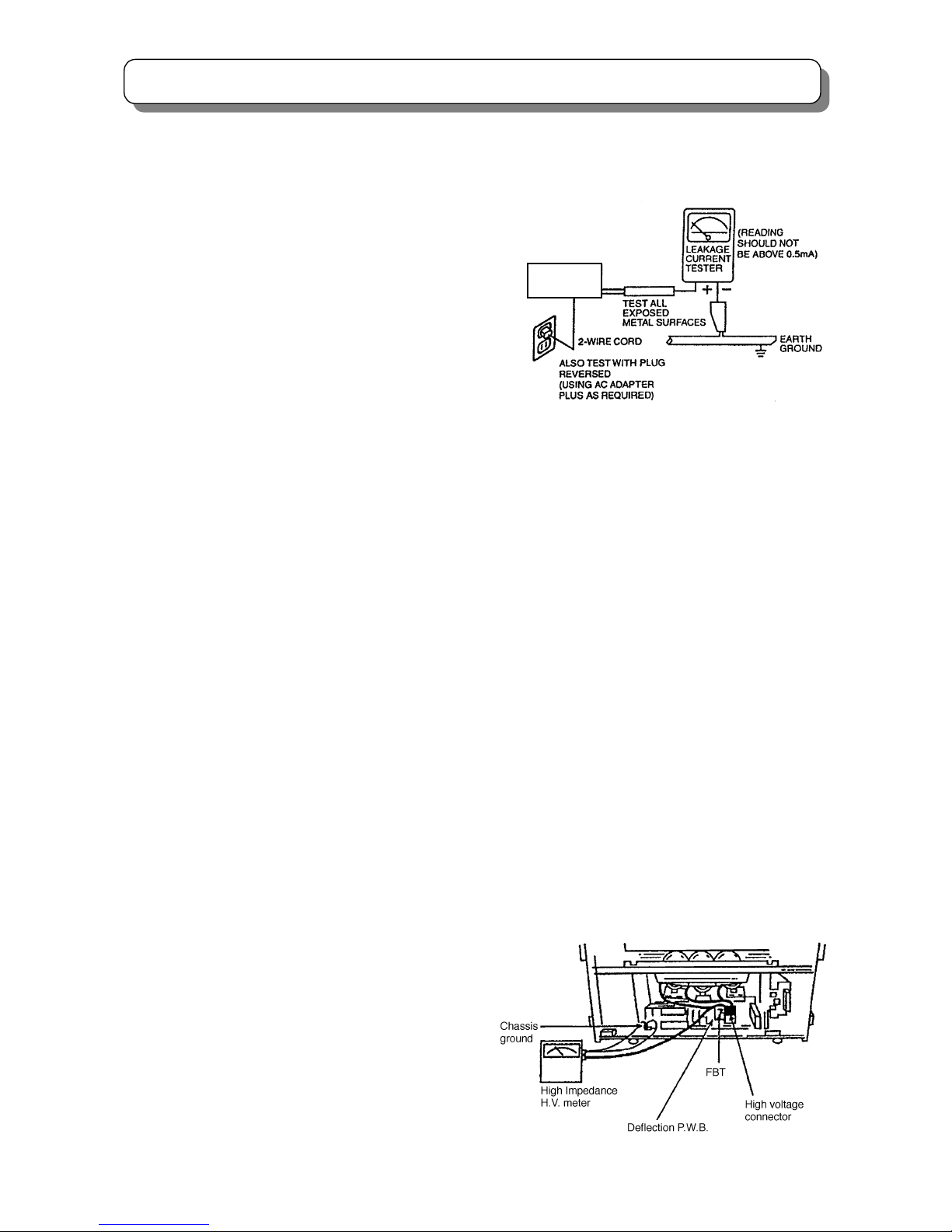
d) Leakage Current Hot Check - With the instrument
completely reassembled, plug the AC line cord
directly into a 220V outlet. (Do not use an isolation
transformer during this test.) Use a leakage current
tester or a metering system with the instrument AC
switch first in the ON position and then in the OFF
position, measure from a known earth ground (metal
water-pipe, conduit, etc.), to all exposed metal parts
of the instrument (antennas, handle bracket, metal
cabinet, screw heads, metallic overlays, control
shafts, etc.), especially any exposed metal parts that
offer an electrical return path to the chassis. Any
current measured must not exceed 0.7 milliamps.
Reverse the instrument power cord plug in the outlet
and repeat test. (See the following connection
diagram)
AC Leakage Test
ANY MEASUREMENTS NOT WITHIN THE LIMITS
SPECIFIED HEREIN INDICATE A POTENTIAL
SHOCK HAZARD THAT MUST BE ELIMINATED
BEFORE RETURNING THE INSTRUMENT TO THE
CUSTOMER OR BEFORE CONNECTING THE
ANTENNA OR ACCESSORIES
e) High Voltage - This receiver is provided with a hold
down clearly indicating that voltage has increased in
excess of a predetermined value. Comply with all
notes described in this Service Manual regarding
this hold down circuit when servicing, so that this
hold down circuit may correctly be operated.
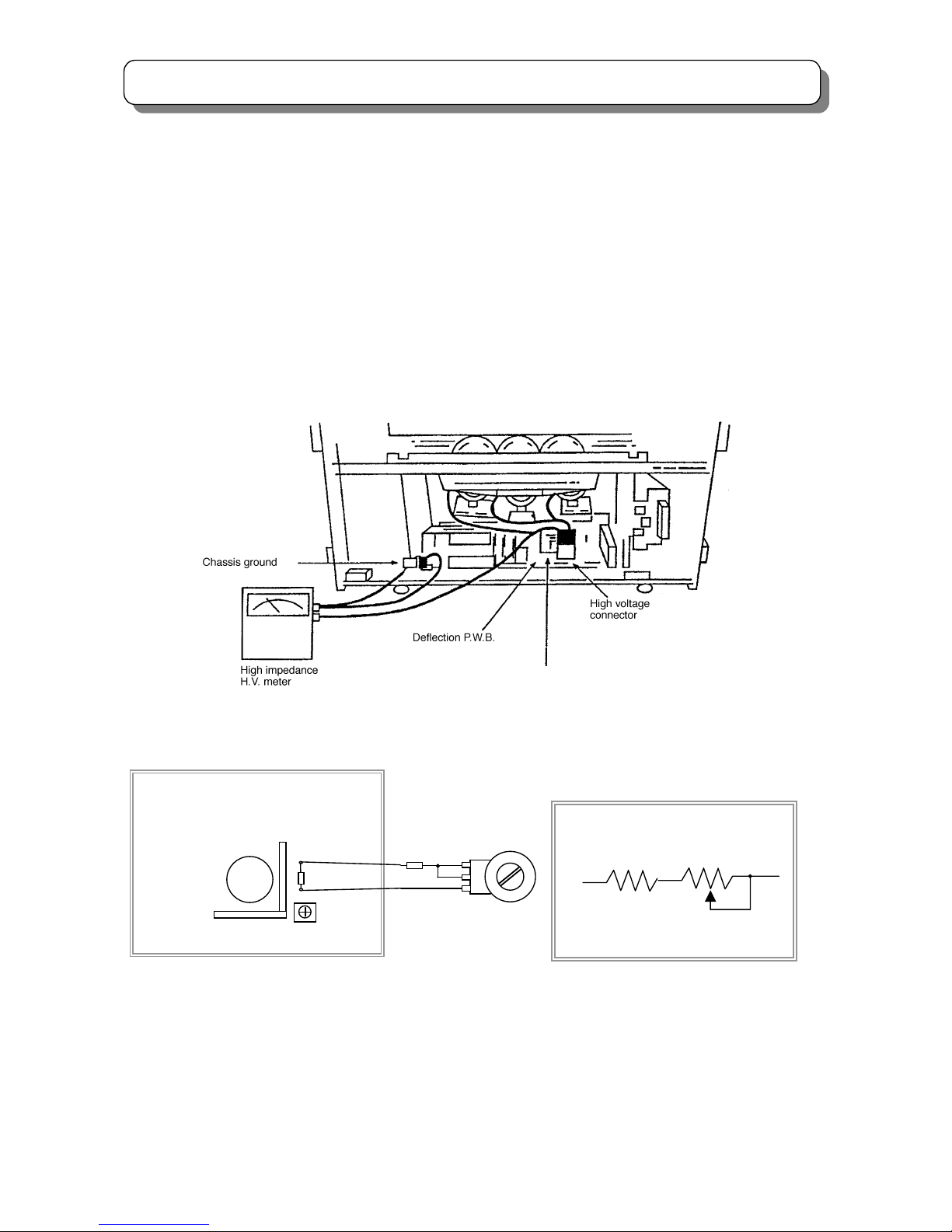
f) Service Warning - With maximum contrast,
operating high voltage in this receiver is lower than
30.9kV(4:3 Model) or 31.9kV(16:9 Model). In case if
any component having influence on high voltage is
replaced, confirm that the high voltage with
maximum contrast is lower than 30.9kV(4:3 Model)
or 31.9kV(16:9 Model). To measure H.V use a high
impedance H.V. meter. Connect (-) to chassis earth
and (+) to the CRT anode button. (See the following
connection diagram).
Note: Must turn power switch off before the connection
to the anode button is made.
(TH02)
INSTRUMENT
UNDER TEST
Page 4
4
SAFETY PRECAUTIONS
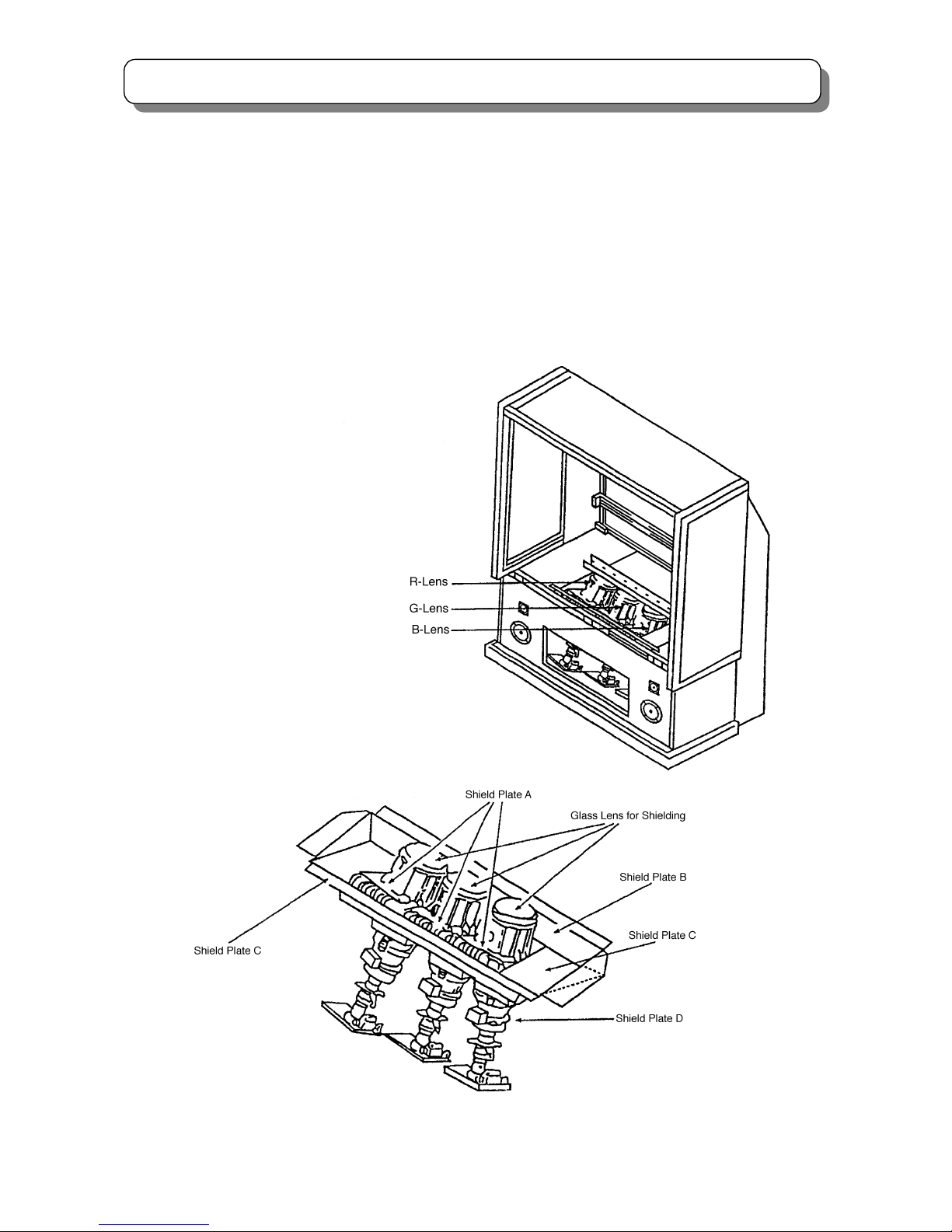
Fig. 1 X-ray shield plates
g) X-radiation (TUBE) -The primary source of
X-radiation in this receiver is the picture tube. The tube
utilized for the above mentioned function in this
chassis is specially constructed to limit X-radiation
emissions.
For continued X-radiation protection, the replacement
tube must be the same type as the original. HITACHI
approved type.
When troubleshooting and making test measurements
in a receiver with a problem of excessive high voltage,
avoid being unnecessarily close to the picture tube
and the high voltage component.
Do not operate the chassis longer than is necessary
to locate the cause of excessive voltage.
h) X-radiation Shield -This receiver is provided with
X-ray shield plates for protection against X-radiation.
Do not remove X-ray shield plates A, B, C, or D
shown in Fig.1 unnecessarily, when troubleshooting
and/or making test measurements.
To prevent X-radiation, after replacement of picture
tube and lens, confirm these components to be fixed
correctly to bracket and cabinet, and not to be taken
off easily.
Page 5

5
SAFETY PRECAUTIONS
2. Read and comply with all caution and safety-related
notes on or inside the receiver cabinet, on the
receiver chassis, or on the picture tube.
3. Design Alteration Warning - Do not alter or add to
the mechanical or electrical design of this TV receiver.
Design alterations and additions, including but not
limited to circuit modifications and the addition of
items such as auxiliary audio and/or video output
connectors, might alter the safety characteristics of
this receiver and create a hazard to the user. Any
design alterations or additions may void the
manufacturer’s warranty and may make you, the
servicer, responsible for personal injury or property
damage resulting therefrom.
4. Picture Tube Implosion Protection Warning - The
picture tube in this receiver employs integral
implosion protection. For continued implosion
protection, replace the picture tube only with one of
the same type number. Do not remove, install, or
otherwise handle the picture tube in any manner
without first putting on shatterproof goggles equipped
with side shields. People not so equipped must be
kept safely away while picture tubes are handled.
Keep the picture tube away from your body. Do not
handle the picture tube by its neck.
5. Hot Chassis Warning
a) Some TV receiver chassis are electrically connected
directly to one conductor of the AC power cord and
may be safely serviced without an isolation
transformer only if the AC power plug is inserted so
that the chassis is connected to the ground side of the
AC power source. Confirm that the AC power plug is
inserted correctly with an AC voltmeter by measuring
between the chassis and a known earth ground. If a
voltage reading in excess of 1.0V is obtained, remove
and reinsert the AC power plug in the opposite polarity
and again measure the voltage potential between the
chassis and a known earth ground.
b) Some TV receiver chassis normally have 85V AC
(RMS) between chassis and earth ground regardless
of the AC plug polarity. These chassis can be safely
serviced only with an isolation transformer inserted in
the power line between the receiver and the AC power
source, for both personnel and test equipment
protection.
c) Some TV receiver chassis have a secondary ground
system in addition to the main chassis ground. This
secondary ground system is not isolated from the AC
power line. The two ground systems are electrically
separated by insulating material that must not be
defeated or altered.
6. Observe original lead dress. Take extra care to assure
correct lead dress (the AC supply, high voltage and
antenna wiring) in the following areas:
a) Near sharp edges
b) Near thermally hot parts
Be sure that leads and components do not touch
thermally hot parts. Always inspect in all areas for
pinched, out-of -plate, or frayed wiring; Do not
change spacing between components and the printed
circuit board; Check AC power cord for damage.
7. Components, parts, and/or wiring that appear to have
overheated or are otherwise damaged should be
replaced with components, parts or wiring that meet
original specifications. Additionally, determine the
cause of overheating and/or damage and, if
necessary, take corrective action to remove any
potential safety hazard.
8. PRODUCT SAFETY NOTICE - Many TV electrical
and mechanical parts have special safety-related
characteristics some of which are often not evident
from visual inspection, nor can the protection they
give necessarily be obtained by replacing them with
components rated for higher voltage, wattage, etc.
Parts that have special safety characteristics are
identified by a
! in the replacement parts list. Use of
substitute replacement that does not have the same
safety characteristics as the recommended
replacement part in the parts list might create shock,
fire, and/or other hazards. Product safety is under
review continuously and new instructions are issued
whenever appropriate. For the latest information,
always consult the appropriate current service
literature. A subscription to, or additional copies of
service literature may be obtained at a nominal
charge from manufacturer.
Page 6

6
LEAD FREE SOLDERING GUIDE
● Lead free solder
With some exception, this product is going to use lead free solder (unleaded) to help preserve the
environment from the September of 2004. Please read these instructions before attempting any soldering
work.
Caution: Always wear safety glasses to prevent fumes or molten solder from getting into the eyes.
Lead free solder can splatter at high temperatures. (600ºC).
■ Lead free solder indicator
There is a F mark made behind the name of PWB or close to its on the printed circuit boards with lead free
solder.
■ Properties of lead free solder
The melting point of lead free solder is 40--50ºC higher than lead solder.
■ Servicing solder
Unleaded solder with an alloy composition of Sn-3.0Ag-0.5Cu is recommended. Although servicing with
leaded solder is possible, there are a few precautions that have to be taken. (Not taking these precautions
may cause the solder to not harden properly, and lead to consequent malfunctions.)
■ Precautions when using leaded solder
● Remove all lead free solder from soldered dots when replacing components.
● If leaded solder should be added to existing unleaded soldered dots , melt the leaded solder thoroughly
and mix it in the unleaded solder after the unleaded soldered dots have been completely melted. (It’s not
permitted to solder directly with soldering iron without solder)
■Servicing soldering iron
A soldering iron with a temperature setting capability (temperature control function) is recommended. The
melting point of unleaded soldering tin is higher than that of leaded ones. Use a soldering iron that maintains
a high stable temperature (large heat capacity) and allows temperature adjustment according to the parts
awaiting serviced to avoid poor servicing performance.
■ Recommended soldering iron
● Soldering iron with temperature control function (temperature range:320--450ºC)
Recommended temperature range per part:
PARTS Soldering iron temperature
Mounting (chips) on mounted PCB 320ºC±30ºC
Mounting (chips) on empty PCB 380ºC±30ºC
Chassis, metallic shield, etc. 420ºC±30ºC
Page 7
7
7
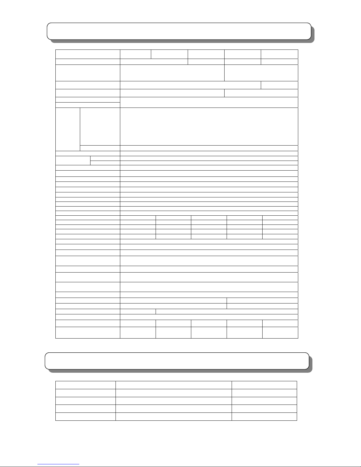
SPECIFICATIONS
CIRCUIT PROTECTION
Fuse (or Device) Circuit Protected Physical Location
F101(T4AL/250V)
AC POWER CIRCUIIT Power Supply Unit (U901)
F102(T2.5AL/250V)
SIGNAL POWER CIRCUIT Power Supply Unit (U901)
F103(T1AL/250V)
STAND BY CIRCUIT Power Supply Unit (U901)
FP01(T4AL/250V)
PRIMARY POWER CIRCUIT Power / Deflection PWB
Model
C43-FL7000 C43-FD7000 C50-FD7000 C47-WD7000 C57-WD7000
Screen size 109cm 127cm 119cm 145cm
Cathode Ray Tube
R: P16LXL00 RFA(SC)
G: P16LXL00 HHA(SC)
B: P16LXL00 BMB(SC)
R: P16MAB00 RFA
G: P16MAB00 HHA
B: P16MAB00 BMB
Lens HSA type HSB type
Anode voltage 30.7KV 31.7KV
Power supply
Power consumption
Refer to the values as indicated on the rating label pasted at the back of the TV set.
PAL B.G/I/D.K
SECAM B.G/D.K
NTSC 50
M/NTSC
NTSC3.58-5.5/6.0/6.5
NTSC4.43-5.5/6.0/6.5
RF/VIDEO
PAL/SECAM 60
Reception
system
COMPONENT 480i / 480p / 576i / 576p / 720p / 1080i
Frequency range 44MHz-863 MHz
VHF Not less than 250uVReception
sensit
ivity
U
HF Not l
ess
than
350u
V
Antenna input impedance 75 Ohm non balance type
Speaker Φ12×2 、Φ5×2
Sound output
20 W×2
Comb filter 3L(PAL)/3D(NTSC)
Perfect volume
Ye s
NICAM/A2 Yes
BBE Ye s
SRS Yes
Magic focus (Auto Convergence) Yes
Manual Convergence Adjustment Yes
P i n P No Yes Yes Yes Ye s
A
V Network Infra-Red System No Yes Yes Yes Yes
PHOTO input (USB input) No No No Yes Yes
PC input (VGA input) No No No Yes Yes
Simply Remote Control No No No Yes Yes
Fastext Ye s
S-VIDEO input
1( side),2(back
)
VIDEO input
1 (side),4(back)
Component input
(Y, PB/CB, PR/CR)
2 (back)
AUDIO (L, R) input
1 (side),4(back)
VIDEO output
(
MONITOR OUT)
1(back)
AUDIO(L,R)output
(MONITOR OUT)
1(back)
Headphone output jack
1 (side)
USB PHOTO input jack
No
1 (Front)
PC VGA input jack
No
1 (side)
AV NET system input jack No 2(back)
Shielding
Ye s
Weight(Kg) 53.5 54.5 71.5 69.5 87.5
Dimension (mm)
(width×height×depth)
969×1237×
456 ㎜
969×1237×
456 ㎜
1119×1362×
498 ㎜
1121×1222×
485 ㎜
1344×1410×
530 ㎜
Page 8
8
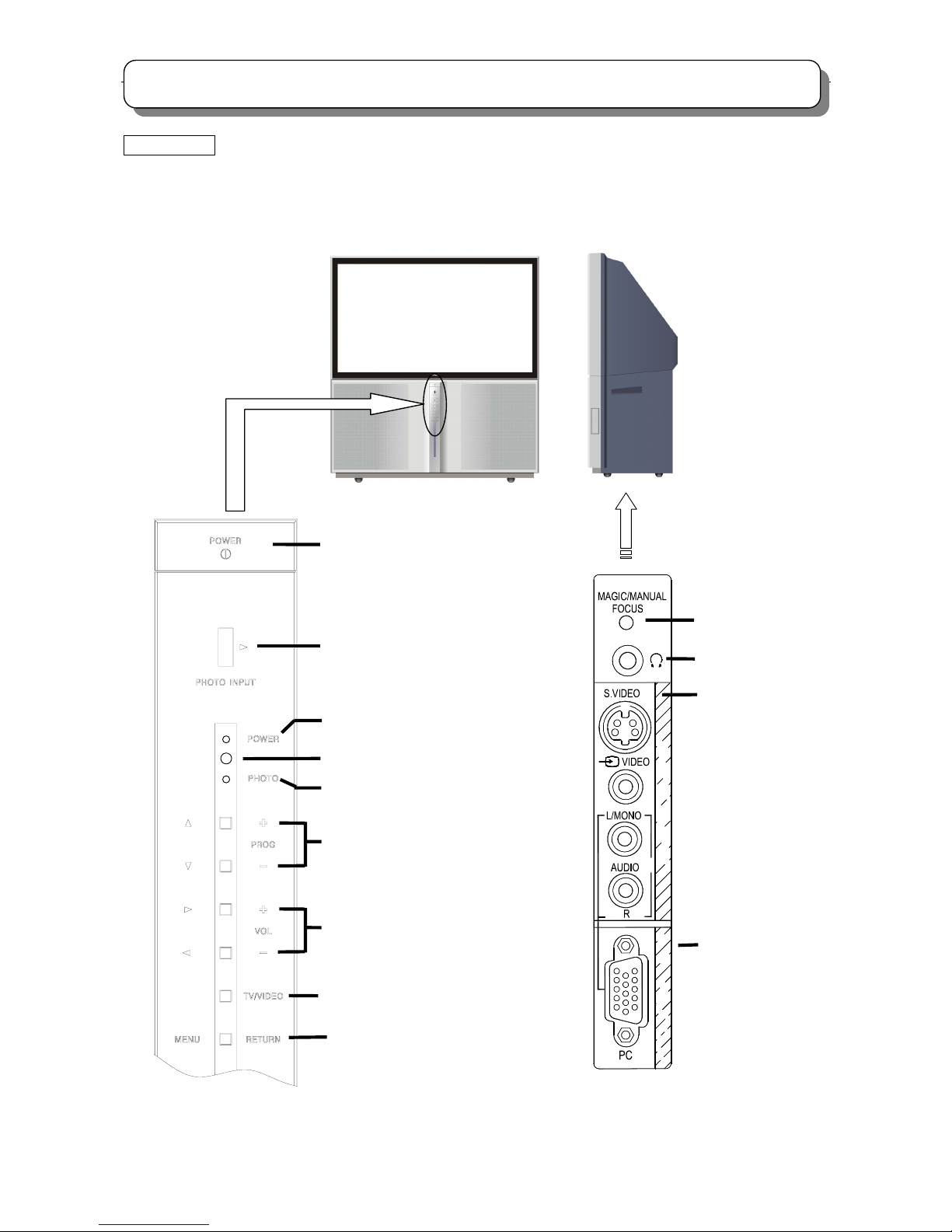
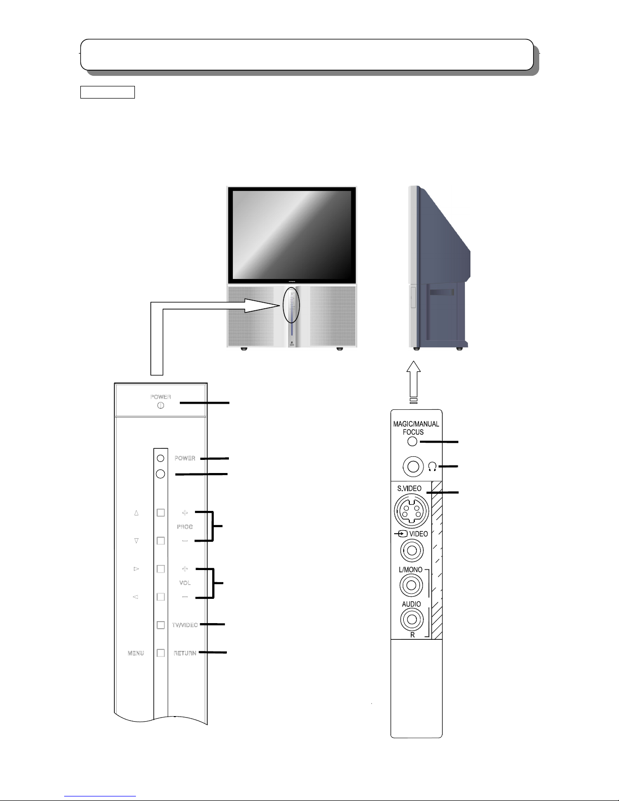
GENERAL INFOMATION
16:9 MODEL
C47-WD7000
C57-WD7000
Control panel and side panel
MENU/RETURN button
5
N
I
U
P
T
N
I
U
P
T
P
C
POWER button
POWER indicator
Remote control sensor
PROGRAM UP/DOWN buttons (When
the menu appears on the screen, press
PROGRAM UP/DOWN buttons to
select the menu up and down.)
VOLUME UP/DOWN buttons (When the
menu appears on the screen, press
VOLUME UP/DOWN buttons to select the
menu right and left.)
TV/VIDEO selector
Photo status indicator (LED)
HEADPHONE jack
MAGIC/MANUAL FOCUS
button
Side panel input jacks
(For AV5 input)
PC INPUT terminal
PHOTO INPUT slot (USB)
Page 9
9
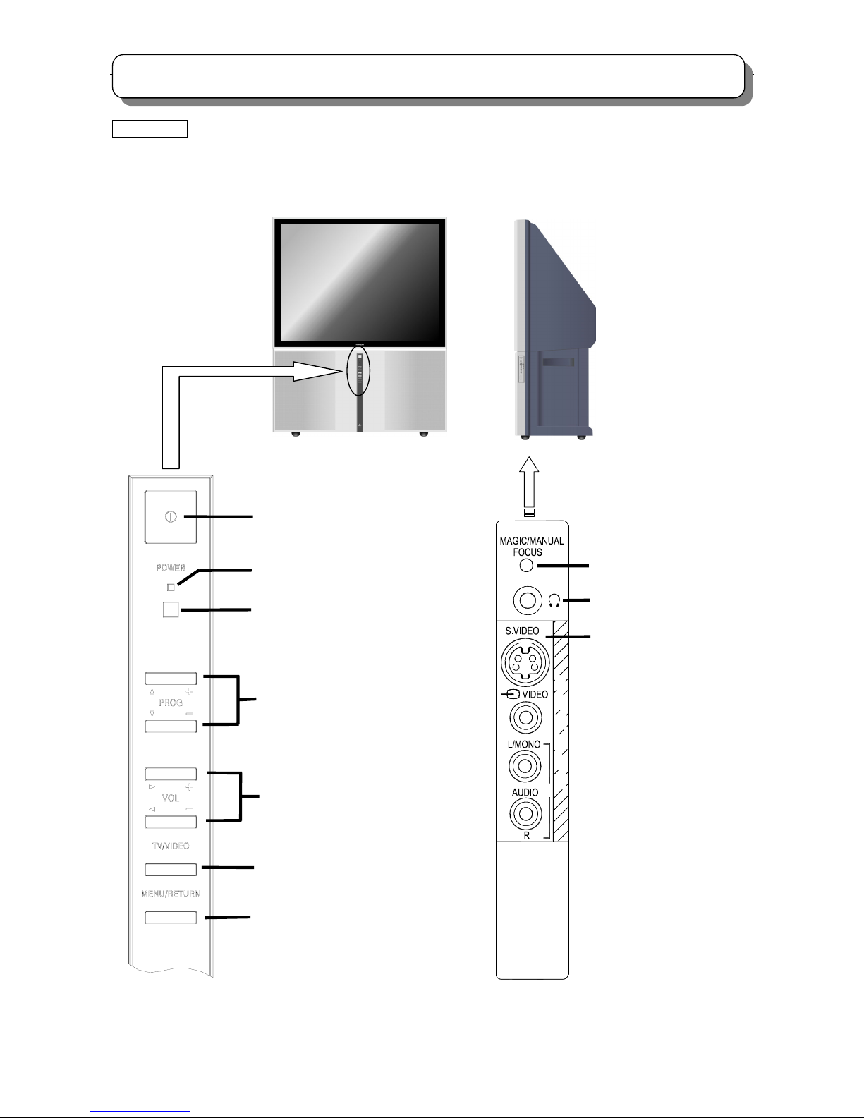
GENERAL INFOMATION
4:3 MODEL
C43-FD7000
C50-FD7000
Control panel and side panel
POWER button
POWER indicator
Remote control sensor
PROGRAM UP/DOWN buttons
(When the menu appears on the
screen, press PROGRAM
UP/DOWN buttons to
select the menu up and down.)
VOLUME UP/DOWN buttons
(When the menu appears on the
screen, press VOLUME
UP/DOWN buttons to select the
menu right and left.)
TV/VIDEO selector
MENU/RETURN button
5
N
I
U
P
T
MAGIC/MANUAL FOCUS
button
Side panel input jacks
(For AV5 input)
HEADPHONE jack
Page 10
10
GENERAL INFOMATION
4:3 MODEL
C43-FL7000
Control panel and side panel
5
N
I
U
P
T
POWER button
POWER indicator
Remote control sensor
PROGRAM UP/DOWN buttons (When
the menu appears on the screen, press
PROGRAM UP/DOWN buttons to
select the menu up and down.)
VOLUME UP/DOWN buttons (When the
menu appears on the screen, press
VOLUME UP/DOWN buttons to selec
t
the menu right and left.)
TV/VIDEO selector
MENU/RETURN
button
HEADPHONE jack
MAGIC/MANUAL FOCUS
button
Side panel input jacks
(For AV5 input)
Page 11
11
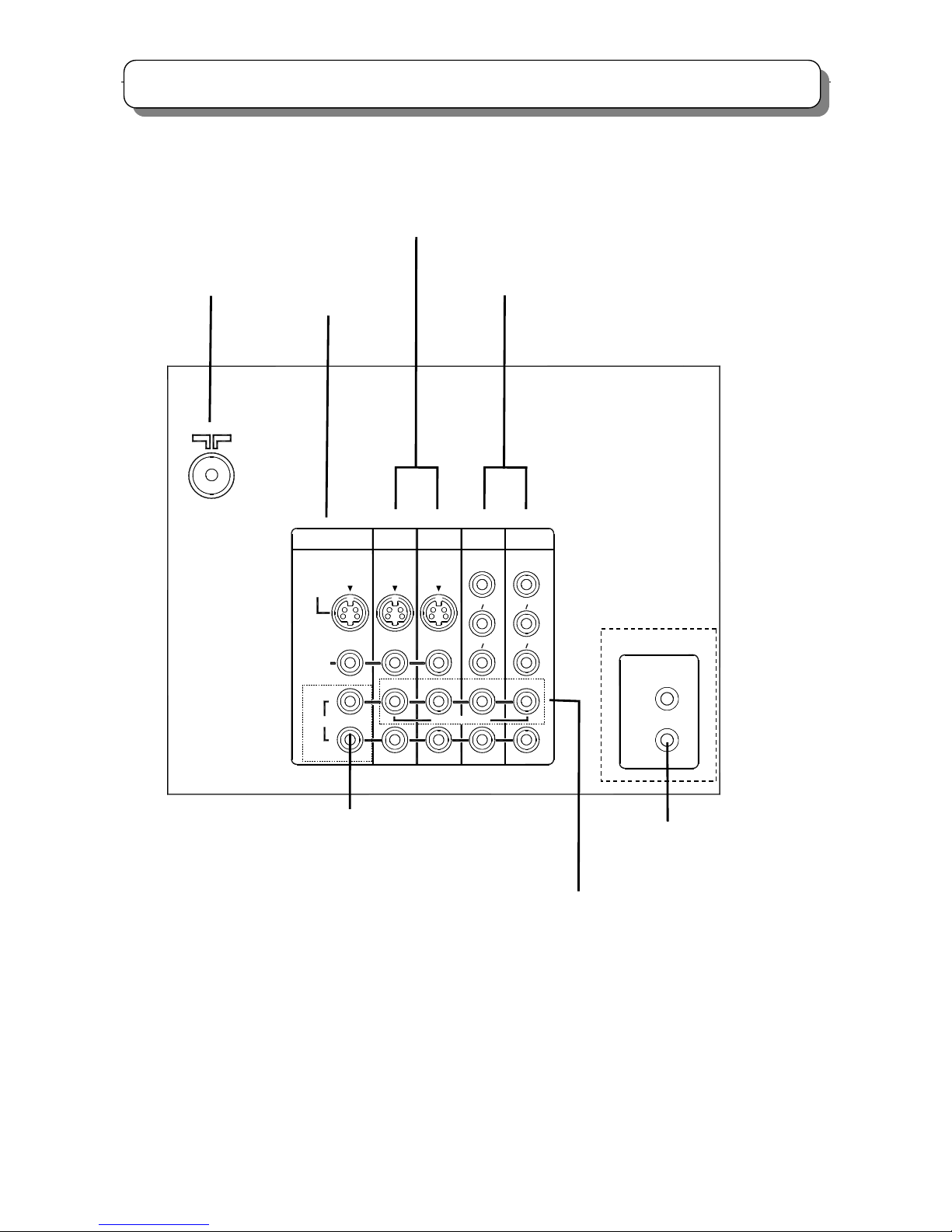
GENERAL INFOMATION
Rear panel
L
R
VIDEO
MONITOR OUT
(MONO)
C
P
RR
C
P
BB
Y/
INPUT 4
INPUT 3
INPUT 1
INPUT 2
S-VIDEO
AUDIO
VARIABLE
FIXED/
VIDEO
C
P
RR
C
P
BB
Y/
VIDEO
TV AS CENTER
BLASTER
IR
(MONO) (MONO) (MONO)
Fixed/Variable Audio output terminals
Antenna terminal
Monitor outpu
t
terminals
Audio/Video input terminals 3,4
Audio/Video input & Component
input terminals 1,2
IR BLASTER output jacks
(Note: C43-FL7000 hasn’t this jack.)
TV AS CENTER input jacks
Page 12

12
CAUTIONS WHEN CONNECTING/DISCONNECTING THE HV CONNECTOR
O
O
L L
L
Perform the following when the
HV connector (anode connector)
is removed or inserted for PRT
replacement, etc.
During Insertion
1. Please refer to direction for insertion as shown in Fig. 4 (L position). Insert connector until “CLICK” sound is heard.
2. Make sure the connector is pressed right in, so that it has a good contact with the spring.
3. Confirm the contact by pulling the connector slightly. (Don’t pull hard because it may damage the connector).
4. Cover the high voltage output by carefully pushing silicon cover onto it. (Don’t turn the connector).
(REMARK)
1. Make sure the silicon cover is
covering the high voltage output.
During Removal
1. Roll out silicon cover from FBT’s contact area slowly.
2. While turning the connector about 90 degrees following the
arrow (from L position to O position), push the connecto
r
slightly towards the case. (Fig .3)
3. Remove the connector slowly by pulling it away from the
case.
Fig. 3 Remove the anode connector
Fig. 4 Insert the anode connector
Page 13
13
TECHNICAL CAUTIONS
High Voltage limiter circuit operation check
1. Turn off TV and delete resistor RH19 (82KΩ) in the Power/Deflection PWB, set 50KΩ VR fully clockwise(maximum
resistance).
2. Set the AC input to 220V AC and turn on TV.
3. Confirm test pattern on PRT is a usable picture, then slowly adjust 50KΩ VR until the picture disappears and TV
shuts down.
4. When the limiter circuit is operating properly, High Voltage will be less than 35.6kV(maximum brightness and
contrast).
5. Turn off TV immediately after checking High Voltage limiter circuit operation.
6.Unplug TV for one minute to reset shutdown circuit. Remove the jig A, and then add resistor RH19(82KΩ)to the PWB.
Jig A
FBT
TH02
POWER/DEFLECTION PWB
Fig.2 High Voltage limiter circuit operation check
FBT
RH19
33 KΩ
50 KΩ VR
Connect Jig A to PWB between RH19
RH17
33 KΩ
50 KΩ VR
Page 14

14
CPU(I004)PIN_FUNCTION
PIN PIN_NAME FUNCTION I/O
1 V HOLD1
Vertical Hold
I
2 HLF1
Filter 1
I/O
3 DM_RXD
Communication RXD
I/O
4 DM_TXD
Communication TXD
I/O
5 P92/TB2IN
NC
I/O
6 IR_IN
REMOTE IR Input
I/O
7 M-S SYNC DET
Sync Detect(M/S)
I/O
8 BYTE
Byte(GND)
I
9 FLASH(CNVSS)
CNVSS(FOR PROGRAM)
I
10 P87/XCIN
NC
I/O
11 P86/XCOUT
NC
I/O
12 RESET
Reset
I
13 XOUT
OSC Output
O
14 VSS
VSS(GND)
-
15 XIN
OSC Input
I
16 VCCI
VCCI(+3.3V)
-
17 OSC1/OSCHLF
OSC 1
I
18 OSC2
OSC 2
O
19 POWER LED
Power LED Output
I/O
20 M-S V COUNT IN
NC
I/O
21 OSD BLK
OSD BLK Output
O
22 HALF TONE
OSD Translucence
O
23 M-S V COUNT IN
NC
I/O
24 HDMI DEC OUT
NC
I/O
25 SD SELECT
SYNC SELECT
I/O
26 WDT CLOCK
WDT CLOCK
I/O
27 HV COUNT SELECT
HV Sync Count
I/O
28 SCL2
IIC CLOCK 2
I/O
29 SCL1
IIC CLOCK 1
I/O
30 SDA1
IIC DATA 1
I/O
31 SDA2
IIC DATA 2
I/O
32
OSD_R OSD_R Output
O
33
OSD_G OSD_G Output
O
34
OSD_B OSD_B Output
O
35
TXD
TXD(FOR PROGRAM)
I/O
36
RXD
RXD(FOR PROGRAM)
I/O
37
SCL
SCLK(FOR PROGRAM)
I/O
38
BUSY
BUSY(FOR PROGRAM)
I/O
39 SCL3
IIC CLOCK 3
I/O
40 SDA3
IIC DATA 3
I/O
41 FLASH EPM
EPM(FOR PROGRAM)
I/O
42 DCU BUSY
DCU BUSY Control
I/O
43 DCU SIZE
DCU SIZE Control
I/O
44 MAGIC SW OUT
NC
I/O
45 MAGIC SW IN
NC
I/O
46 FLASH (CE)
CE(FOR PROGRAM)
I/O
47
CUT OFF OUT CUT OFF Output
I/O
48 ABL SW OUT
ABL SWITCH Output
I/O
49 VMUTE
VIDEO MUTE
I/O
50 DCU ADJ OUT
NC
I/O
51 FC DATA IN
FC DATA Input
I/O
PIN PIN_NAME FUNCTION I/O
52 FC DATA OUT
FC DATA output
I/O
53 FC DATA CLOCK CLOCK FOR FC I/O
54 FC ENABLE
FC ENABLE Control
I/O
55 DCU IR OUT
NC
I/O
56 DCU IR SEL
NC
I/O
57 MC LED OUT
MC LED Level Output
O
58 POWER LED OUT
Power LED Level Output
O
59 POWER ON/OFF
Power ON/OFF Control
I/O
60 IRB IR SEL
NC
I/O
61 MC ENABLE
MC MODE ENABLE
I/O
62 OSD H SYNC IN
OSD H SYNC Input
I
63 MC WAKEUP OUT
MC MODE CONTROL
I/O
64 OSD V SYNC IN
OSD V SYNC Input
I
65 SCL5
IIC CLOCK 5
I/O
66 SDA5
IIC DATA 5
I/O
67 28KHz OUT 28KHz Control O
68 TEXT RESET
TEXT RESET
I
69 WSP RESET
WSP RESET
I/O
70 V SQUEEZE OUT
Vertical Squeeze Output
O
71 AUDIO MUTE
AUDIO MUTE Output
I/O
72 KEY OUT(2) KEY OUT(2) I/O
73 AV5 DET
AV 5 Input Detect
I/O
74 AV1 DET
AV 1 Input Detect
I/O
75
KEY OUT(1) KEY OUT(1)
I/O
76 APC OUT
APC CONTROL
I/O
77 PC/OTHER SEL
PC/OTHER SELECT
I/O
78 P12/D10
NC
I/O
79 LIGHT OUT
LIGHT ON/OFF
I/O
80 HP DET
HP DETECT
I/O
81 KEY IN(2) KEY IN(2) I/O
82 KEY IN(1) KEY IN(1) I/O
83 APC(M) Out APC(M) Output I/O
84
IF SYS1(S) OUT SUB IF SYS1(S)
I/O
85
IF SYS1(S) OUT MAIN IF SYS1(M)
I/O
86
IF SYS2(M) OUT MAIN IF SYS2(M)
I/O
87
IF SYS2(S) OUT SUB IF SYS2(S)
I/O
88 IR RESET
IR BLASTER RESET
I/O
89 AGC IN (S)
SUB AGC Input
I/O
90 AGC IN (M)
MAIN AGC Input
I/O
91 DIP DETECT
NC
I/O
92 SUB AFC IN
SUB AFC Input
I/O
93 MAIN AFC IN MAIN AFC In
p
ut I/O
94 AD KEY IN
AD_KEY IN
I/O
95 - - 96 - - 97 - - 98 - - 99 VCCE
VCCE(5V)
I
100 - - -
Page 15

15
TROUBLE SHOOTING
Is click sound
of Relay heard?
Are 2 Green LEDs
turned OFF at the
same time?
IC101,DS101,C105,
PC102,ZD101,T101 etc.
Check Check
Check
No
Raste
r
Is Voltage at
pin(1) of IP01
more than 1.3V?
Has Fuse FP01
blown?
RP03, RP04,
RP05, RP06
YES
YES
YES YES
NO
Is base Voltage
Of Q709 normal?
Does raster
ppear with (47) and (44
)
Of PPS1 shorted?
Are Voltages
At both ends of T702
(primary side)
normal?
IY04 pin(37)
-H out,
IY04 pin(31)
I2L_Vdd
etc.
T702, R748,
R730
etc.
Q777, QH01,
T701, TH02
etc.
NO
NO
YES
YES
Is Voltage
at pin(16) of I004
3.3V?
Is Voltage
at pin(59) of I004
“H”?
Q018, Q021,
etc.
Replace U901
Check
Check
Check
Check
Check
IP01, QP01,
QP02, RP11,
RP12, RP13
etc.
Replace FP01
Check
I004
Check
YES
YES
Check
I013, I004
YES
Check
Find LED(s) that is
Turned dark or OFF
Earlier than the other.
(1) No raster and no power (How to check LED’s Diagnosis)
(Power Supply Unit)
(Power Supply Unit)
(Signal PWB)
(Signal PWB)
(Signal PWB)
(Pow Def PWB)
(Pow Def PWB)
(Pow Def PWB)
(Power Supply Unit)
(Pow Def PWB)
(Pow Def PWB)
Is Voltage
at pin(13) of PPS1
5.2V?
SW+28/-28V
line
EP01, EK01,
DP30, DP31,
DP50
etc.
SW+115V line
EP02, DP40,
DP34, Q777,
QH01, Q701,
TH02, T701
etc.
Replace U901
(Pow Def PWB)
NO
NO
NO
YES
NO
NO
NO
NO
1.Turn OFF
the power SW.
2.Wait for 3 seconds.
3.Turn ON again after
several seconds, and
observe green LEDs
carefully.
Page 16
16
TROUBLE SHOOTING
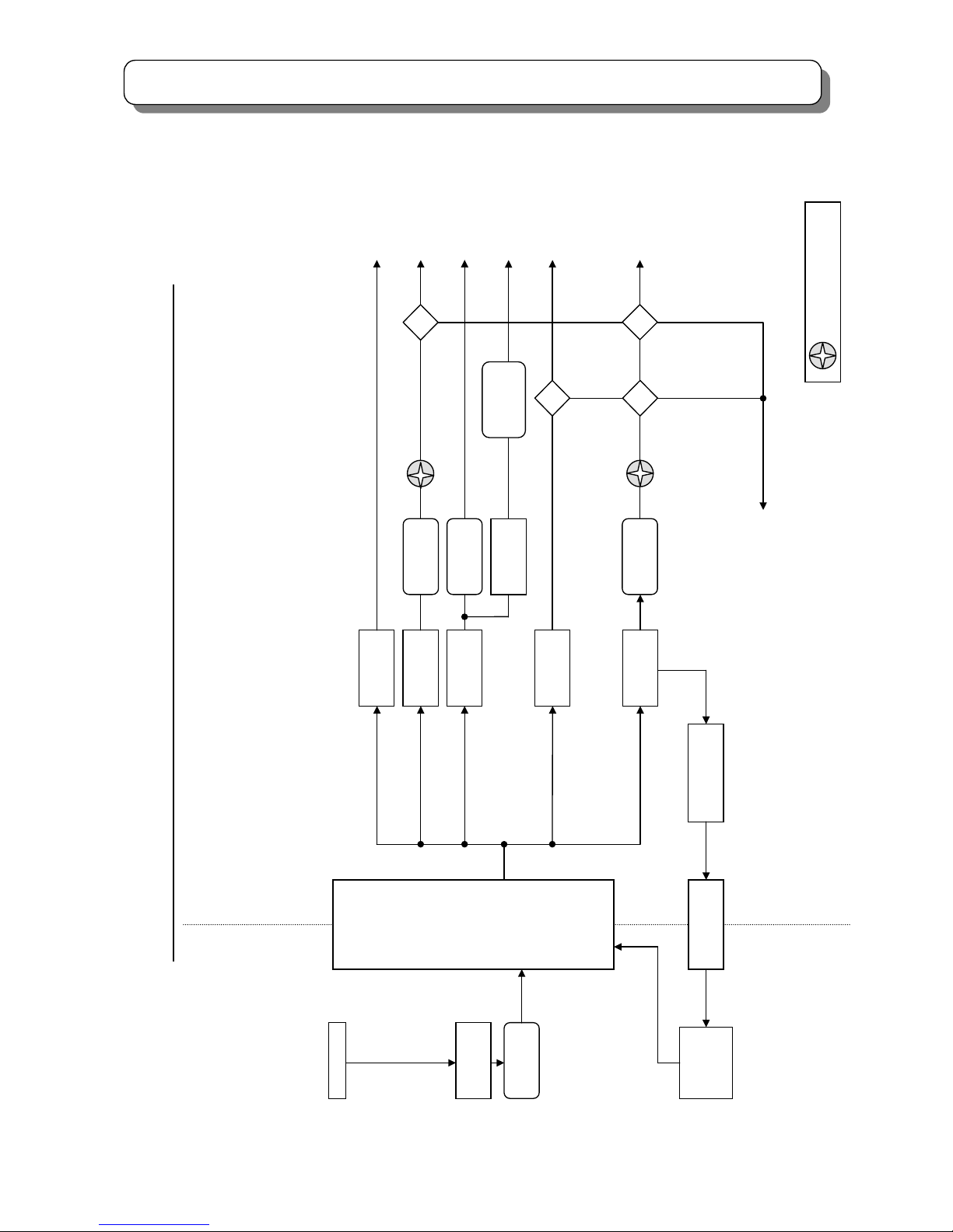
(2) PROPTECTION CIRCUIT BLOCK DIAGRAM
DP40:+115V
Switching
Transformer
TP01
LIVE COLD
Feed Back
IP02
Rectifier
+220V:DP33
Rectifier
+28V:DP30
Rectifier
+115V:DP34
Protector
EP02:3000
Rectifier
-28V:DP31
DP50:+28V
DP39:>150V
QP05:>1.5
A
Q
ZD
DP46:>32V
ZD
DP46:>-24V
ZD
Voltage Control
+115V:IP03
Short CCT.
Detector
Over Voltage
Detector
= GREEN LED
DP4M Protection
C
ircuit
Bloc
k
Dai
g
ram
(
Deflection
Power Su
pp
l
y
)
Switching
Control
IP01
AC Input
Rectifier
DP01
Fuse
FP01:4A
Deflection:
SW+115V
Conver / DCU:
SW-28V
Conver / Vert:
SW+28V
Video:
SW+220V
DCU:
SW+7V
Rectifier
+7V:DP32
Regulator
+6.3V:QP04
Heater:
SW+6.3V
Protector
EK01:2000
Protector
EP01:7000
Protector
EP03:2000
Page 17
17
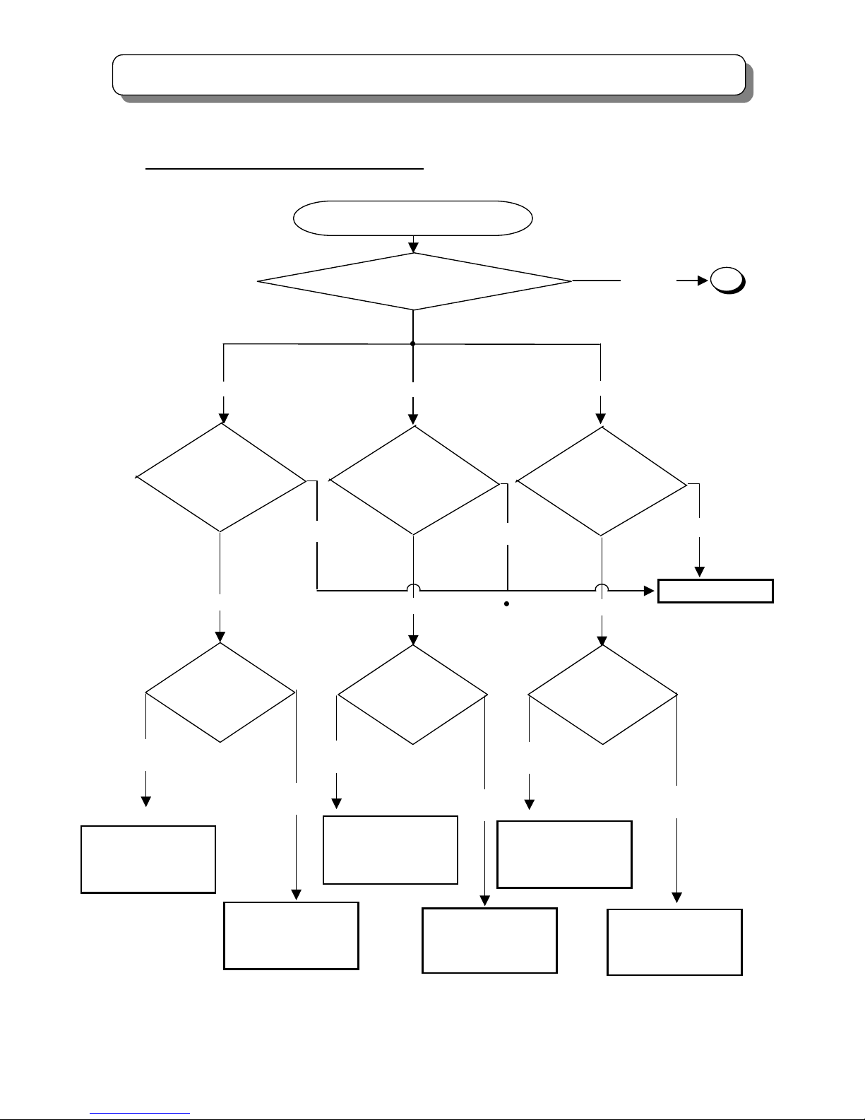
TROUBLE SHOOTING
OK
NG
A
All Color
(3) Convergence be not corrected (How to check ?)
Convergence be not corrected
Green
Red
Blue
NG
NG
OK
OK
Which color has shifted?
DCU CHANGE
CHECK & CHANGE
RK57/RK58 (RV)
IK40 (CY Amp)
Which has shifted,
VERTICAL line or
HORIZONTAL line?
Which has shifted,
VERTICAL line or
HORIZONTAL line?
CHECK & CHANGE
RK53/RK54 (RH)
IK40 (CY Amp)
Which has shifted,
VERTICAL line or
HORIZONTAL line?
HORIZONTAL
line
VERTICAL
line
HORIZONTAL
line
CHECK & CHANGE
RK69/RK70 (GH)
IK40 (CY Amp)
VERTICAL
line
CHECK & CHANGE
RK73/RK74 (GV)
IK41 (CY Amp)
HORIZONTAL
line
CHECK & CHANGE
RK61/RK62 (BH)
IK41 (CY Amp)
VERTICAL
line
CHECK & CHANGE
RK65/RK66 (BV)
IK41 (CY Amp)
DCU out CHECK
PDCU 4pin (RH)…(*1)
PDCU 5pin (RV)…(*2)
DCU out CHECK
PDCU 6pin (GH)…(*1)
PDCU 7pin (GV)…(*2)
DCU out CHECK
PDCU 8pin (BH)…(*1)
PDCU 9pin (BV)…(*2)
Page 18

18
TROUBLE SHOOTING
NG
NG
OK
OK
CHECK
RK53,54,57,58,69,70,73,74,61,62,
65,66
CY Amp (IK40,41),
CHECK
DEFLECTION circuit
CHECK
IK01
SW +7V line (EK01)
QK01
CHECK DCU input ;
LK02 (V.BLK)
…(*3)
CHECK DCU input ;
is Voltage at LK04/KC01
(LK03/KC02)5V?(-5V?)
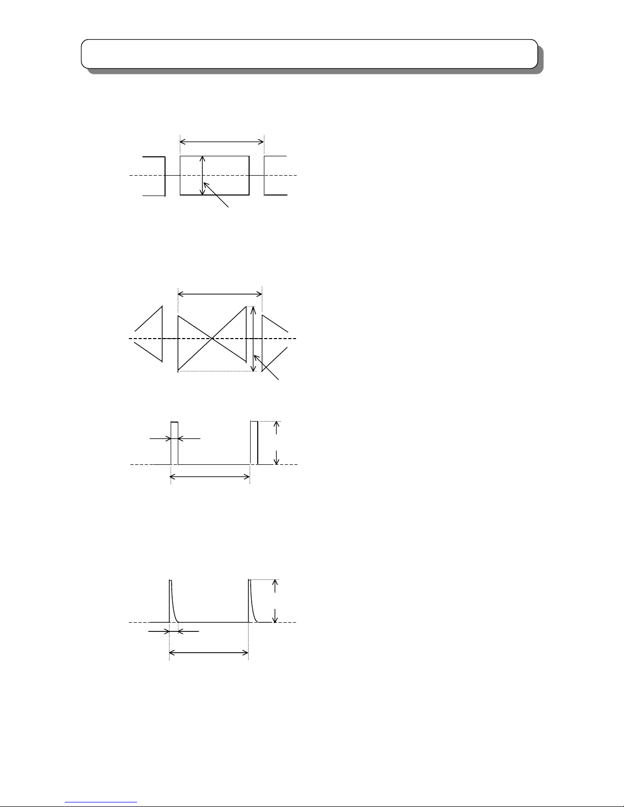
(*1) PDCU 4 pin (RH)
PDCU 6 pin (GH)
PDCU 8 pin (BH)
(*3) LK02 (V. BLK.)
GND
GND
16~17[ms]
16~17[ms]
16~17[ms]
Vpp =4~5 [V]
Vpp =2~5 [V]
(*2) PDCU 5 pin (RV)
PDCU 7 pin (GV)
PDCU 9 pin (BV)
GND
A
Page 19
19
TROUBLE SHOOTING
(*3)H.BLK
NTSC 60Hz 29.6μs
PAL 100Hz 32.0μs
PAL 50Hz 32.0μs
PAL HD 50Hz 35.6μs
(*1)
Vp-p=2~5V
GND
NTSC 60Hz 16.7ms
PAL 100Hz 10.0ms
PAL 50Hz 20.0ms
PAL HD 50Hz 20.0ms
(*2)
GND
Vp-p=2~5V
(*4)V.BLK
NTSC 60Hz 16.7ms
PAL 100Hz 10.0ms
PAL 50Hz 20.0ms
PAL HD 50Hz 20.0ms
NTSC 60Hz 16.7ms
PAL 100Hz 10.0ms
PAL 50Hz 20.0ms
PAL HD 50Hz 20.0ms
GND
4~5V
5μs
GND
4~5V
0.8
~1.2ms
Page 20
20
TROUBLE SHOOTING
How to Adjust 9 Point Manual Convergence
Adjustment Preparation
Receive RF or Video signal.
Adjustment Procedure
Press and hold the MAGIC/MANUAL FOCUS button for more than 3 seconds to enter the MANUAL CONVERGENCE
mode.
(1) Press the [▲] [▼] [◄] [►] cursor buttons to select adjustment point, press the [ENTER] button to display frame of red,
move the [▲] [▼] [◄] [►] cursor buttons to adjust red convergence for better.
(2)Press the [ENTER] button to display frame of blue, press the [▲] [▼] [◄] [►] cursor buttons to adjust blue convergence
for better.
(3)Press the [ENTER] button to display frame of white, press the [▲] [▼] [◄] [►] cursor buttons to select another
adjustment point, then perform (1)~(2) to adjust.
(4)When adjustment is done, press the [MENU] button, then the following screen will display as below.
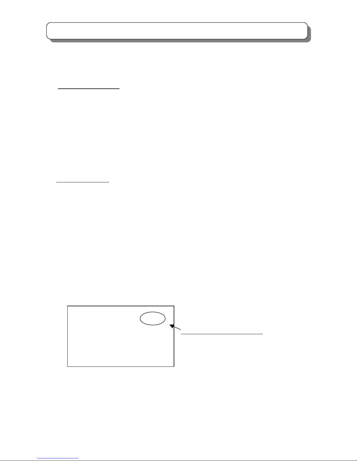
[0]:
Cancel adjusted data and exit from adjustment mode.
[1]:
Save your adjusted data and exit from adjustment mode.
[2]:
Return to manual convergence mode.
[3]:
Recall the adjusted data of the previous auto convergence and
return to manual convergence mode.
Note:
If there is no operation for 3 minutes from the remote control unit, the TV
will exit from MANUAL CONVERGENCE mode.
PLEASE
ENTER NUMBER
CANCEL :[ 0 ]
DONE :[ 1 ]
BACK :[ 2 ]
RESET :[ 3 ]
Release the MAGIC/MANUAL
FOCUS button.
Press and hold the
MAGIC/MANUAL FOCUS
button more than 3 seconds.
MANUAL FOCUS
Page 21
21
TROUBLE SHOOTING
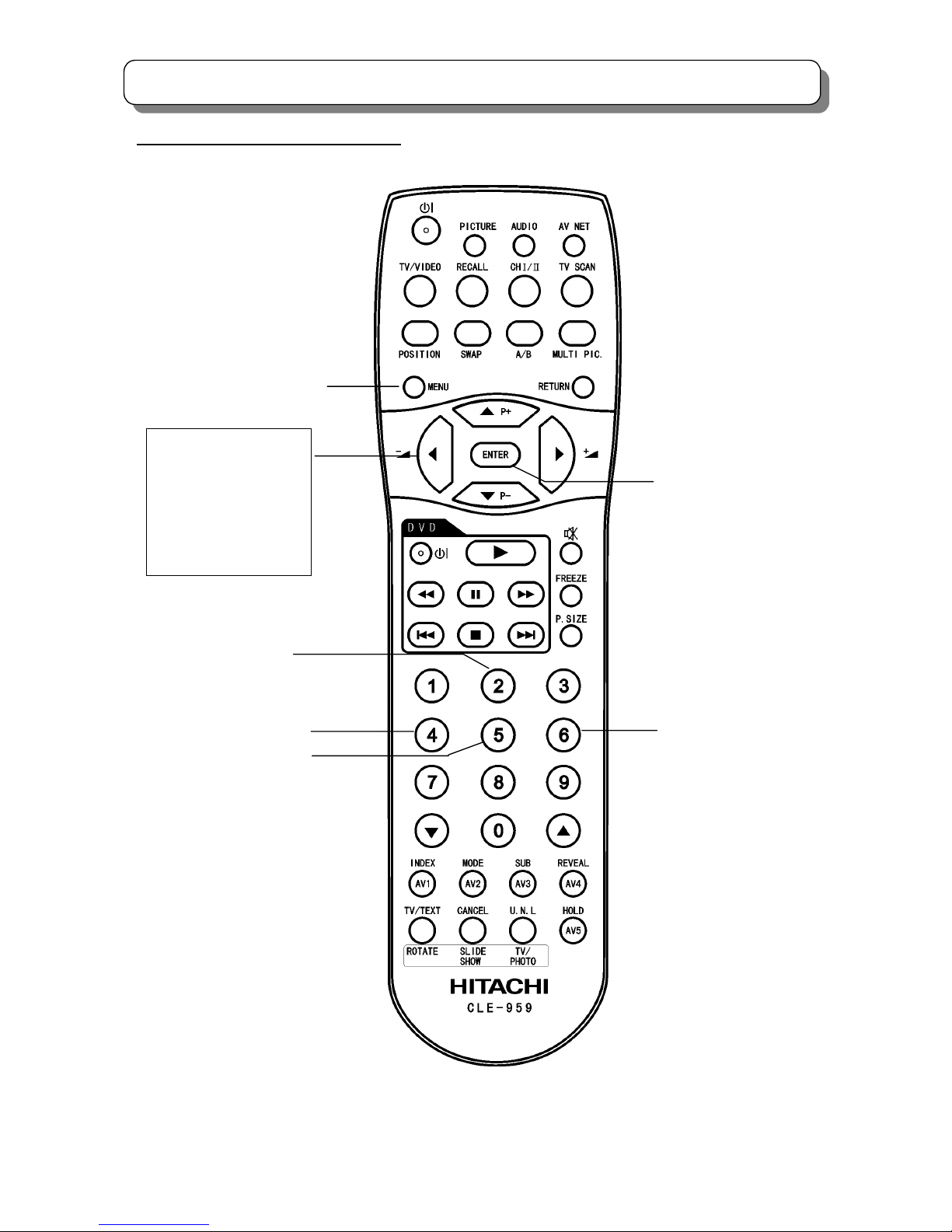
9 Point Manual Adjustment remote control
Note: This page is taken the remote control unit of CLE-959 as an example to illustrate, the remote control unit of CLE-956
has the same function.
CURSOR RIGHT
CURSOR LEFT
CURSOR DOWN
MENU
CHANGE COLOR
(Red & Blue)
〔▲〕:UP
〔▼〕:DOWN
〔 〕:LEFT
〔 〕:RIGHT
A
DJUSTMENT
▼
▼
Page 22

22
TROUBLE SHOOTING
Trouble Shooting Guide for DP4M
No
Item Changed Adjustment necessary
1 Signal PWB
White Balance/Sub-brightness.
Tuner (AGC)
Horizontal phase/Vertical phase
2
Tuner (Main/Sub),I001
AGC
3 Microprocessor (I004) No adjustment necessary
4 FC unit No adjustment necessary
5 Sub signal PWB Tint adjustment
6
Audio control/amplifier
IR01 (MSP3455G)
IA02 (TA8258H)
IA01 (NJW1160)
No adjustment necessary
7 EEPROM (I007)
Memory initialize and all adjustments in service menu
8
Video chroma IC IG04,IQ02(TB1274AF)
Tint adjustment
9
Deflection Control/RGB IC
IY04 (TA1360)
White Balance /Sub-brightness
Horizontal position (50Hz/60Hz)
10
Convergence/Deflection PWB
Sub Deflection PWB
Horizontal /Vertical size;
Trapezoid distortion adjustment
Side pin adjustment; High voltage adjustment
Cut off (screen) adjustment; DCU phase data setting;
Raster Position Adjustment; Focus adjustment
Convergence adjustment (includes magic focus initialize);
11 DCU unit (UKDG)
Raster Position Adjustment; DCU phase data setting;
Convergence adjustment (includes magic focus initialize)
Phase data
12 Terminal PWB; Power PWB No adjustment necessary
13 Sensor PWB, Sensor Convergence adjustment; Magic focus initialize
14 PRT tube
Pre Heatrun; Cut off (screen) adjustment;
All related lens adjustment(focus etc.);
Blue Defocus Adjustment; White Balance; Sub Brightness;
Convergence adjustment (includes magic focus initialize)
15 CPT PWB
All related lens adjustment (focus, etc. )
White Balance; Convergence (includes magic focus initialize)
16 DY coil
Horizontal /Vertical size; Raster Tilt/Position Adjustment;
Side pin adjustment; Trapezoid distortion adjustment
Convergence adjustment (includes magic focus initialize)
17
Deflection Control IC
IH01 (M62501P), FBT (TH02)
High voltage adjustment;
Cut off (screen) adjustment
Page 23

23
SERVICE ADJUSTMENTS
SERVICE ADJUSTMENT ITEMS:
1.1 MEMORY INITIALZE······································································································· 24
1.2 MODEL SETUP··············································································································· 24
1.3 MAIN AGC ADJUSTMENT ····························································································· 25
1.4 SUB AGC ADJUSTMENT ······························································································· 26
2.1 CUT OFF ADJUSTMENT································································································ 27
2.2 DCU PHASE DATA SETTING························································································· 28
2.3 RASTER TILT ADJUSTMENT ························································································ 29
2.4 BEAM ALIGNMENT ········································································································ 31
2.5 RASTER POSITION ADJUSTMENT ·············································································· 32
2.6 SIDE PIN DISTORTION ADJUSTMENT ········································································· 33
2.7 VERTICAL SIZE ADJUSTMENT ···················································································· 34
2.8 HORIZONTAL SIZE ADJUSTMENT ··············································································· 35
2.9 TRAPEZOID DISTORTION ADJUSTMENT···································································· 37
2.10 BEAM FORM ADJUSTMENT·························································································· 38
2.11 LENS FOCUS ADJUSTMENT ························································································· 39
2.12 STATIC FOCUS ADJUSTMENT ······················································································ 43
2.13 DYNAMIC FOCUS CHECK ····························································································· 44
2.14 DIGITAL CONVERGENCE ADJUSTMENT····································································· 45
2.15 BLUE DEFOCUS ADJSUTMENT···················································································· 62
2.16 WHITE BALANCE ADJUSTMENT·················································································· 63
2.17 SUB BRIGHTNESS ADJUSTMENT················································································ 65
2.18 SUB PICTURE ADJUSTMENT························································································ 66
2.19 TINT ADJUSTMENT········································································································ 67
2.20 MAGIC FOCUS INITIALIZE····························································································· 68
3.1 PRT CABINET LOCATION ····························································································· 70
3.2 FOCUS PACK ················································································································· 70
3.3 MAIN P.W.B····················································································································· 71
Page 24
24
SERVICE ADJUSTMENTS
Before performing SERVICE ADJUSTMENTS★ ,please refer to the “TROUBLE SHOOTING”。
1.1 Memory initialize
When replacing signal P.W.B or EEPROM(I007), it requires perform Memory Initialize operation.
Adjustment Procedure
(1)Link the PSRT① and PSRT② for longer than 3 seconds.
(Please refer to page 71 .)
(2)Wait until the OSD “1” is displayed (It takes several 10 seconds.) , this means initialization is
completed and each settings become factory preset condition.
Do not unplug the outlet or perform any key operation until the initialization is completed.
1.2 Model Setup
Adjustment Procedure
(1) Set following items in service menu according to a model.
(2) After set the Items according to the following tables in Service Menu, Set to INIT3 by following method.
(The model is set up by this operation.
And initial-setting values according to the model is set up by this operation. At the same time, each settings
become factory preset condition)
(a) Select item No.627(INIT3) in service menu and press and hold the [recall] key on the remote handset until the
OSD background changes to yellow. (It takes about 3 seconds.)
(b) Wait until the OSD background color becomes normal (It takes several 10 seconds.) , this means initialization
is completed and each settings become preset condition according to the model .
Do not unplug the outlet or perform any key operation until the initialization is completed.
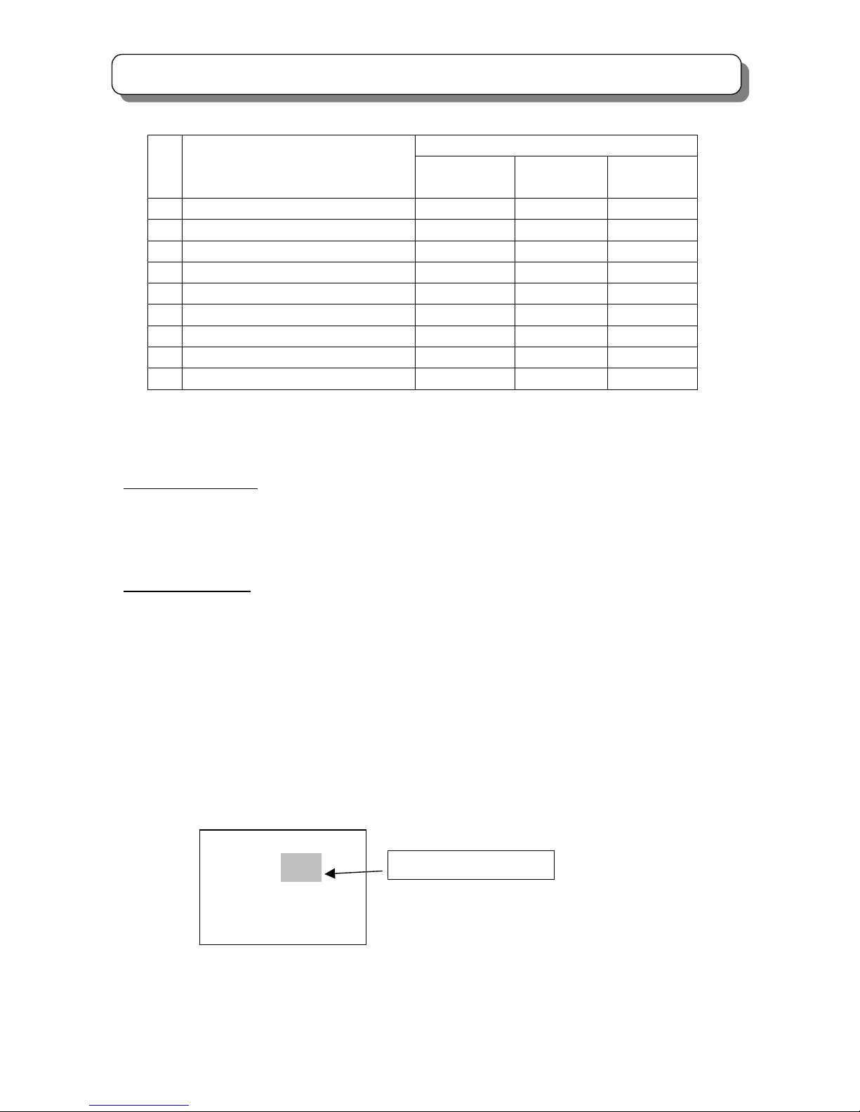
(3) Check the setting state displayed on the upper right of a service menu.
V201-1DB5 FC100-7B05 MC010 011111111
N
o. Data C:PAL S:6.5 Scan:V-HD
0: 0
1: 1
2: 0
3: 0
The state of Model Select setting
・From the left to the 1st figure:The state of Model Select1
…
・From the left to the 9th figure:The state of Model Select9
Page 25
25
SERVICE ADJUSTMENTS
(Continued)
Model Name No. Value
C47-WD7000 /
C57-WD7000
C43-FD7000 /
C50-FD7000
C43-FL7000
1
Model Select1:ASPECT
1 0 0
2
Model Select2:DESTINATION
1 1 1
3
Model Select3:LIGHT
1 1 0
4
Model Select4:MULTI_PICTURE
1 1 0
5
Model Select5:COLOR_MANAGER
1 1 0
6
Model Select6:PC
1 0 0
7
Model Select7:AV_ NET
1 1 0
8
Model Select8:PHOTO
1 0 0
9
Model Select9:HD
1 1 1
1.3 MAIN AGC ADJUSTMENT
Adjustment Preparation
(1) To prevent circuit temperature drift, the set must be warmed up before alignment longer than 10 minutes.
(2) Adjust the RF signal frequency and level accuracy to 623.25MHz and -50dBm.
(3) Check the ATT Function is OFF.
Adjustment Procedure
(1) Receive ch27 China or ch40 CCIR. (623.25MHz, -50dBm) in service mode.
(2) Select item No.11 in service menu by [▲] or [▼]key.
(3-1) When the value of AGC of NO.11 of a service menu is 235 or less than 235,
(3-1-1) Push [►] of remote control and set AGC value becomes 235 or greater than 235.
(3-1-2) Push the [ENTER] button of remote control, then AGC adjustment is completed.
(3-2) When the value of AGC of NO.11 of a service menu is 235 or greater than 235.
(3-2-1) Set the value of AGC by [◄] of remote control to smaller than 235 at first.
(3-2-2) Then push [►] of remote control and set the AGC value again to greater than and as close as 235.
(3-2-3)Push the [ENTER] button of remote control, then AGC adjustment is completed.
N
o. V0XX
11 34 235
12 54 234
13 64
14 32
The Value of AGC
Page 26

26
SERVICE ADJUSTMENTS
1.4 SUB AGC ADJUSTMENT
Adjustment Preparation
(1) To prevent circuit temperature drift, the set must be warmed up before alignment longer than 10 minutes.
(2) Adjust the RF signal frequency and level accuracy to 623.25MHz and -50dBm.
Adjustment Procedure
(1) Press [MULTI PIC.] button to display sub picture, and receive the [Multi PIC.], ch27 China or ch40 CCIR (623.25MHz,
-50dBm) in adjustment mode.
(2) Select item No.12 in service menu by [▲] or [▼] key.
(3-1) When the value of AGC of NO.12 of the service menu is 235 or less than 235,
(3-1-1) Push [►] of remote control and set the AGC value becomes 235 or greater than 235.
(3-1-2)Push the [ENTER] button of remote control, then AGC adjustment is completed.
(4-2)When the value of AGC of NO.12 of the service menu is 235 or greater than 235.
(4-2-1) Set the value of AGC by [◄] of remote control to smaller than 235 at first.
(4-2-2) Then push [►] of remote control and set the AGC value again to greater than and as close as 235.
(4-2-3) Push the [ENTER] button of remote control, then AGC adjustment is completed.
Page 27

27
SERVICE ADJUSTMENTS
2.1 CUT OFF ADJUSTMENT
Adjustment preparation
(1) Pre heat-run should be finished.
(2) Confirm item No. 45(R cut off),46(G cut off) and 47 (B cut off)are set to 127 in service menu.
(3) Confirm item No.43(R DRV) and No.44(G DRV) are set to 63 in service menu.
Adjustment procedure
(1) Go to “SERVICE” mode item No 10 by using JIG R/C.
Press [►] key to enter CUT OFF adjustment mode.
(2) Screen VR (R, G and B) should be turned clockwise gradually and set the condition that the each horizontal
line is just beginning to appear.
(3) Press [◄] key to return normal mode.
Page 28
28
SERVICE ADJUSTMENTS
2.2 DCU PHASE DATA SETTING
Adjustment preparation
(1) Cut off adjustment should be finished.
Adjustment procedure
(1) Receive PAL signal (RF or VIDEO) and Set to 100Hz mode. (User menu-> FUNCTION \ SCAN MOD
E \ 100Hz ) Contrast should be set Center and other control be set normal.
(2) Push the “SERVICE ONLY” switch on the POWER/DEF P.W.B. to enter the adjustment mode of the digital
convergence unit.
(3) Phase set
(3-1) Press the [REVEAL] key on R/C to display the green cross-hatch pattern.
(3-2) Press the [CH Ⅰ/Ⅱ] key to recall the phase DATA on screen.
4:3 model C43-FD7000 / C50-FD7000 / C43-FL7000
PAL 100i mode(100Hz Mode) PAL 50p mode NTSC 60p mode
16:9 model C47-WD7000 / C57-WD7000
PAL 100i mode(100Hz Mode) PAL 50p mode NTSC 60p mode PAL HD mode
(3-3) If phase data is not the same as above, change the DATA by using the following R/C keys.
Press [4] or [6] key to adjust the PH-H
Press [2] or [5] key to adjust the PH-V
Press [ ] or [ ] key to adjust the CR-H
Press [▲] or [▼] key to adjust the CR-V
(3-4) Press the [REVEAL] key to exit from phase mode.
(3-5) Press [INDEX] key on R/C twice to write the data into ROM.
(3-6) Push the “SERVICE ONLY” switch on the POWER/DEF P.W.B. twice to exit from adjustment mode of the
digital convergence unit.
PHASE MODE: 1
PH-H: F7
PH-V: 0D
CR-H: 35
CR-V: 1C
1
PHASE MODE: 6
PH-H: EF
PH-V: 09
CR-H: 30
CR-V: 14
PHASE MODE: 5
PH-H: F7
PH-V: 19
CR-H: 35
CR-V: 1C
PHASE MODE: 1
PH-H: FA
PH-V: 0A
CR-H: 38
CR-V: 1C
PHASE MODE: 6
PH-H: F2
PH-V: 06
CR-H: 33
CR-V: 14
PHASE MODE: 5
PH-H: FB
PH-V: 16
CR-H: 38
CR-V: 1C
PHASE MODE: 2
PH-H: F8
PH-V: 03
CR-H: 35
CR-V: 14
Page 29

29
SERVICE ADJUSTMENTS
(3-7) Change to PAL50p mode (PAL signal input, User Menu setting-> FUNCTION \ SCAN MODE \ PROGRESSIVE)
and repeat procedure (2)-(3) for PAL50p mode.
(3-8) Change to NTSC60p mode (NTSC signal input, User Menu setting-> FUNCTION \ SCAN MODE \
PROGRESSIVE) and repeat procedure(2)-(3) for NTSC60p mode.
[16:9 model only]
(3-9) Change to PAL HD (*) mode, and repeat procedure (2)-(3) for PAL HD mode.
(*)Setting Procedure of PAL HD mode.
(a)Receive 1080i(50Hz)
(b)Set the Picture mode to Favorite.
Film mode : Off
Dynamic Contrast : Off
Color Manager : Off
(c)Set Picture Size to 16:9 mode.
2.3 RASTER TILT ADJUSTMENT (DEFLECTION YOKE ADJUSTMENT)
Adjustment preparation
(1) Face the set East or West.
(2) Receive the NTSC cross-hatch signal.
(3) Contrast should be set MAX. and the other controls should be set CENTER.
(4) The lens focus should be coarsely adjusted.
(5) The electrical focus should be coarsely adjusted
(6) The digital convergence should not be corrected.
(7) Turn the Main power SW. off.
(8) Press and hold the “SERVICE ONLY” SW. on POWER/DEF P.W.B. and switch on the Main power.
Adjustment procedure
(1) Apply covers to the R and B lenses or short the TS (2P EH Connector) on R and B CPT P.W.B. to project only
green beam.
(2) Then loose DY's screws (R,G,B) BEFORE start alignment of Raster Tilt.
Page 30
30
SERVICE ADJUSTMENTS
(3) Turn the G deflection yoke and adjust the Vertical raster inclination.
(4) After GREEN Raster was adjusted correctly, then FIX DY Screw (See NOTE for Torque Spec.)
(5) Then, remove the cover of R or B lens and project red or blue light and green light together on the screen.
(6) Turn the deflection yoke of R or B and set so that the inclination of R or B light with respect to the green light
is as shown below on the end sides.
Apply to Red and Blue.
(7) After the adjustment, fix the screw of each DY with a torque of 1.18 Nm(12kgfcm).
L
Vertical center axis of cross-hatch signal
This line is GEOMETRIC
CENTER of PTV Screen.
A
pply to green DY.
L≦ ±2mm
L1, L2≦±2mm
<<Attention>>
A
fter Raster Tilt Adjustment,
Gap of DY & PRT funnel should be Zero
R or B
G
L1
L2
Page 31

31
SERVICE ADJUSTMENTS
2.4 BEAM ALIGNMENT
Preparation for adjustment
(1) Pre-heat 30 minutes or more before the adjustment.
(2) The static convergence data should be cleared.
(3) Raster inclination should be adjusted. Optical focus should be coarsely adjusted.
(4) Contrast should be set MAX and the other control should be set: Center.
(5) Receive the NTSC cross-hatch pattern signal or Dot pattern signal.
(6) Discharge static charge from metallic parts on PRT NECK by using
Short-clip-JIG.
Adjustment procedure
(1) Green (G) tube alignment: Short-circuit TS (2P EH) connectors on the red
( R ) and blue (B) CPT P.W.B.s and project the only green beam.
(2) Set the G tube beam alignment magnet to the cancel state as shown below.
(3) Turn the static focus VR*
1
for Green fully counterclockwise and check
the cross-hatch center position on the screen.
Note : Halo state
(4) Turn the static focus VR*
1
for Green fully clockwise.
(5) Turn 2 sheets of the alignment magnet in either direction and move the
cross-hatch center to the position where is checked in step (3).
(6) Turn the static focus VR*
1
for Green and check if the picture position moves or not.
(7) Repeat steps (2) to (6) until the picture position does not move during step (6)
(8) In the same manner, adjust the Red ( R )*
2
and the Blue (B)*3 tube alignments.
(9) Fix the beam alignment magnet with white paint after the alignment is completed.
*
1
*
2
Static Focus VR is on focus pack UFPK
*3
Page 32

32
SERVICE ADJUSTMENTS
2.5 RASTER POSITION ADJUSTMENT
Preparation for adjustment
(1) Place the set facing east or west.
(2) Receive the NTSC Hitachi circle pattern signal. (Set the NTSC mode)
(3) Contrast control should be set Maximum and the other controls should be set Center.
(4) The raster inclination and beam alignment should be adjusted.
The lens focus and electric focus adjustment should be coarsely adjusted.
(5) The convergence should be uncorrected state.
(6) Press and hold the “SERVICE ONLY” SW. on POWER/DEF P.W.B. and switch on the Main power.
Adjustment procedure
(1) Turn the centering magnets for R, G and B to get the center point of the cross-hatch position within
specification as shown below.
[Horizontal direction]
Unit:mm
R: L
1
to the left from the geometric center of the screen.
L1 ±2mm
B: L
2
to the right from the geometric center of the screen.
L2 ±2mm
G: To geometric center of screen.
Tolerance:±2mm
[Vertical direction]
G,R and B should be the same position as the geometric center of the screen should be within±2mm.
(2) Immediately after the adjustment is completed, fix the R, G and B centering magnets using white paint.
L2 L1
R B
G
Geometric center of the screen
4:3 model 16:9 model
L
1
L2
L1 L
2
L
1
L
2
43” 20 30 47” 20 35
50” 20 30 57” 20 35
Page 33

33
SERVICE ADJUSTMENTS
2.6 SIDE PIN DISTORTION ADJUSTMENT
Adjustment Preparation
(1) PICTURE control should be set Factory Preset condition.
(2) DCU ROM CHECK should be finished.
(3) Place the set facing east.
Adjustment Procedure
PAL 100i MODE I
2
C No.15
(1) Input any PAL signal.
(2) Press [MENU] key.
(3) Choose [FUNCTION] and [Scan Mode], set to [100Hz] mode.
(4) Press [MENU] key to exit from [FUNCTION].
(5) Press and hold the SERVICE ONLY SW. on DEF/CONVER P.W.B. and
[MUTE] key of Handset.
DCU cross-hatch is appeared with Conv. Data cleared.
(6) Press the [TV/VIDEO] key on the front control panel, then SERVICE MENU appears.
(7) Choose SIDE PIN (EW parabola) item by using Handset up/down cursor key.
(8) Adjust SIDE PIN as following by using Handset left/right cursor key.
(9) Press [ENTER] key of handset to write the adjusted data.
(10) After adjustment, press SERVICE ONLY SW. to exit from SERVICE mode.
PAL 50p MODE I
2
C No.19
(1) Input any PAL signal.
(2) Press [MENU] key.
(3) Choose [FUNCTION] and [Scan Mode], set to [Virtual HD] or [Progressive] mode (50P mode).
(4) Press [MENU] key to exit from [FUNCTION].
(5) Adjust the same items as (5)-(10) of setting PAL 100i MODE.
NTSC 60p MODE I
2
C No.23
(1) Input any NTSC signal
(2) Adjust the same items as (5)-(10) of setting PAL 100i MODE.
PAL HD MODE(16:9 Model only) I
2
C No.27
(1) Input any PAL HD signal (1080i/50).
(2) Press [MENU] key.
(3) Choose [FUNCTION] and [Scan Mode], set to HD mode.
(4) Press [MENU] key to exit from [FUNCTION].
(5) Set PAL HD mode referring to P29(*) setting procedure of PAL HD mode.
(6) Adjust the same items as (5)-(10) of setting PAL 100i MODE.
Edge of vertical DCU cross-hatch line should
be straight condition.
N
ote: If it’s impossible to adjust the straight line, se
t
a little pin condition.
Page 34

34
SERVICE ADJUSTMENTS
2.7 VERTICAL SIZE ADJUSTMENT
Adjustment Preparation
(1) PICTURE control should be set Factory Preset condition.
(2) DCU ROM CHECK should be finished.
(3) Place the set facing east.
Adjustment Procedure
PAL 100i MODE I
2
C No.13
(1) Input any PAL signal.
(2) Press [MENU] key.
(3) Choose [FUNCTION] and [Scan Mode], set to [100Hz] mode.
(4) Press [MENU] key to exit from [FUNCTION].
(5) Press and hold the SERVICE ONLY SW. on DEF/CONVER P.W.B. and
[MUTE] key of Handset.
DCU cross-hatch is appeared with Conv. Data cleared.
(6) Press the [TV/VIDEO] key on the front control panel, then SERVICE MENU appears.
(7) Choose V.SIZE (amplitude) item by using Handset up/down cursor key.
(8) Adjust V.SIZE (amplitude) as following by using Handset left/right cursor key.
So that the distance between the horizontal line at the upside line from center line
and underside line from center line of DCU’s cross-hatch pattern.
(9) Press [ENTER] key of handset to write the data.
(10) After adjustment, press SERVICE ONLY SW. to exit from SERVICE mode.
PAL 50p MODE I
2
C No.17
(1) Input any PAL signal.
(2) Press [MENU] key.
(3) Choose [FUNCTION] and [Scan Mode], set to [Virtual HD] or [Progressive] mode (50P mode).
(4) Press [MENU] key to exit from [FUNCTION].
(5) Adjust the same items as (5)-(10) of setting PAL 100i MODE.
NTSC 60p MODE I
2
C No.21
(1) Input any NTSC signal
(2) Adjust the same items as (5)-(10) of setting PAL 100i MODE.
PAL HD MODE(16:9 Model only) I
2
C No.25
(1) Input any PAL HD signal (1080i/50).
(2) Press [MENU] key.
(3) Choose [FUNCTION] and [Scan Mode], set to HD mode.
(4) Press [MENU] key to exit from [FUNCTION].
(5) Set PAL HD mode referring to P29(*) setting procedure of PAL HD mode.
(6) Adjust the same items as (5)-(10) of setting PAL 100i MODE.
Page 35

35
SERVICE ADJUSTMENTS
4:3 model
L PAL 100i
MODE
PAL 50p
MODE
NTSC 60p
MODE
43” 525 525 560
50” 610 610 650
16:9 model
L PAL 100i
MODE
PAL 50p
MODE
NTSC 60p
MODE
PAL HD
MODE
47” 470 470 500 490
57” 545 545 605 575
Tolerance: +/-5mm
Unit: mm
2.8 HORIZONTAL SIZE ADJUSTMENT
Adjustment Preparation
(1) PICTURE control should be set Factory Preset condition.
(2) DCU ROM CHECK should be finished.
(3) Place the set facing east.
Adjustment Procedure
PAL 100i MODE I
2
C No.14
(1) Input any PAL signal.
(2) Press [MENU] key.
(3) Choose [FUNCTION] and [Scan Mode], set to [100Hz] mode.
(4) Press [MENU] key to exit from [FUNCTION].
(5) Press and hold the SERVICE ONLY SW. on DEF/CONVER P.W.B. and
[MUTE] key of Handset.
DCU cross-hatch is appeared with Conv. Data cleared.
(6) Press the [TV/VIDEO] key on the front control panel, then SERVICE MENU appears.
(7) Choose H.SIZE (EW SIZE) item by using Handset up/down cursor key.
(8) Adjust H.SIZE (EW SIZE) as following by using Handset left/right cursor key.
So that the distance between the vertical line at the left line from center line and
right line from DCU’s cross-hatch pattern is L.
(9) Press [ENTER] key of handset to write the data.
(10) After adjustment, press SERVICE ONLY SW. to exit from SERVICE mode.
*L
*L : Between the horizontal line
at the to
p
end and bottom end.
Page 36

36
SERVICE ADJUSTMENTS
PAL 50p MODE I2C No.18
(1) Input any PAL signal.
(2) Press [MENU] key.
(3) Choose [FUNCTION] and [Scan Mode], set to [Virtual HD] or [Progressive] mode (50P mode).
(4) Press [MENU] key to exit from [FUNCTION].
(5) Adjust the same items as (5)-(10) of setting PAL 100i MODE.
NTSC 60p MODE I
2
C No.22
(1) Input any NTSC signal
(2) Adjust the same items as (5)-(10) of setting PAL 100i MODE.
PAL HD MODE(16:9 Model only) I
2
C No.26
(1) Input any PAL HD signal (1080i/50).
(2) Press [MENU] key.
(3) Choose [FUNCTION] and [Scan Mode], set to HD mode.
(4) Press [MENU] key to exit from [FUNCTION].
(5) Set PAL HD mode referring to P29(*) setting procedure of PAL HD mode.
(6) Adjust the same items as (5)-(10) of setting PAL 100i MODE.
4:3 model
L PAL 100i
MODE
PAL 50p
MODE
NTSC 60p
MODE
43” 830 830 830
50” 965 965 965
16:9 model
L PAL 100i
MODE
PAL 50p
MODE
NTSC 60p
MODE
PAL HD
MODE
47” 1010 1010 975 935
57” 1225 1225 1185 1135
Tolerance: +/-5mm
Unit: mm
L
Page 37

37
SERVICE ADJUSTMENTS
2.9 TRAPEZOID DISTORTION ADJUSTMENT
Adjustment Preparation
(1) PICTURE control should be set Factory Preset condition.
(2) DCU ROM CHECK should be finished.
(3) Place the set facing east.
Adjustment Procedure
PAL 100i MODE I
2
C No.16
(1) Input any PAL signal.
(2) Press [MENU] key.
(3) Choose [FUNCTION] and [Scan Mode], set to [100Hz] mode.
(4) Press [MENU] key to exit from [FUNCTION].
(5) Press and hold the SERVICE ONLY SW. on DEF/CONVER P.W.B. and
[MUTE] key of Handset.
DCU cross-hatch is appeared with Conv. Data cleared.
(6) Press the [TV/VIDEO] key on the front control panel, then SERVICE MENU appears.
(7) Choose TRAPEZOID item by using Handset up/down cursor key.
(8) Adjust TRAPEZOID as following by using Handset left/right cursor key.
(9) Press [ENTER] key of handset to write the data.
(10) After adjustment, press SERVICE ONLY SW. to exit from SERVICE mode.
PAL 50p MODE I
2
C No.20
(1) Input any PAL signal.
(2) Press [MENU] key.
(3) Choose [FUNCTION] and [Scan Mode], set to [Virtual HD] or [Progressive] mode (50P mode).
(4) Press [MENU] key to exit from [FUNCTION].
(5) Adjust the same items as (5)-(10) of setting PAL 100i MODE.
NTSC 60p MODE I
2
C No.24
(1) Input any NTSC signal
(2) Adjust the same items as (5)-(10) of setting PAL 100i MODE.
PAL HD MODE(16:9 Model only) I
2
C No.28
(1) Input any PAL HD signal (1080i/50).
(2) Press [MENU] key.
(3) Choose [FUNCTION] and [Scan Mode], set to HD mode.
(4) Press [MENU] key to exit from [FUNCTION].
(5) Set PAL HD mode referring to P29(*) setting procedure of PAL HD mode.
(6) Adjust the same items as (5)-(10) of setting PAL 100i MODE.
Vertical Screen frame line & edge o
f
vertical DCU cross-hatch line should
be parallel condition.
Page 38

38
SERVICE ADJUSTMENTS
2.10 BEAM FORM ADJUSTMENT
Preparation for adjustment
(1) The beam alignment should be completed.
(2) The raster tilt, centering, horizontal and vertical size adjustments should
be completed. Optical focus should be coarsely adjusted.
(3) PICTURE control should be set the Factory Preset condition.
(Contrast : Max, other items : Center)
(4) Input the dot signal.
(5) Aspect : 4:3 standard mode(16:9 Model only).
Adjustment procedure
(1) Green PRT beam shape adjustment
Short-circuit 2P sub-mini connectors on Red and Blue CPT P.W.Bs. to
project only the green beam.
(2) Turn the green static VR*
1
fully clockwise.
Note : Blooming
(3) Using the 4-pole magnet as shown below, modify the dot pattern of the screen
center to make it to a perfect circle.
(4) Repeat the procedure for the Red*
2
and Blue*3 PRT beam shapes.
(5) After the adjustment is completed, return R, G and B static VRs to the best focus point.
(6) After the beam alignment is completed, fix the beam alignment magnet with white paint.
*1
*2 Static Focus VR is on FOCUS PACK UFPK
*3
True circle specification:
4-pole beam shape
correction magnet
2-pole beam alignment
magnet
PRT E. gun side
PRT surface side
a
b
True circle Form Ratio: a/b
Specification: 0.9~1.1
Page 39

39
SERVICE ADJUSTMENTS
2.11 LENS FOCUS ADJUSTMENT
Adjustment preparation
(1) The orientation of PTV set is arbitrary, west, east, north and south.
(2) Centering DY tilt should be adjusted.
(3)Electrical focus adjustment should have been completed.
(4)Drive VR location adjustment should have been completed.
(5) Red : 12 0’clok, Green : 1~2 0’clock)
(6) Receive the NTSC cross-hatch signal.
(7) Contrast control should be set Center and Brightness control should be set minimum.
Adjustment procedure
(1) Loosen the fixing screw or wing nut on the lens cylinder so that the lens cylinder can be turned.
(Be careful not to loosen too much)
After completing steps (4), (5), (6) below, tighten the fixing screws or wing nuts for each lens with a torque of
0.67N.m(7Kgf cm) ~ 1.18N.m(12Kgf cm).
(Do not turn the lens cylinder after having a screw and wing nuts tightened. Also do not tighten the screw too
much, otherwise the lens will be tilted too much or the screw will be broken).
Lens sass Lens sass
(NOTE1) (NOTE2)
Fixing screw Fixing Wing nuts
TYPE 1 TYPE 2
(2) Apply covers to each colors of R, G and B lenses. and project a single color beam on the screen and adjust in
sequence. (The adjustment order of R, G and B is only an example.)
(3) If the lens adjustment knob is tuned clockwise viewed from the front, the color aberration change as follows.
Cross-Hatch Color aberration
Change of color aberration
Short focus Long focus
RED LENS Orange Scarlet
GREEN LENS Blue Red
BLUE LENS Purple Green
Page 40

40
SERVICE ADJUSTMENTS
(4) In case of G lens.
Set to the point where the chromatic aberration switches from blue to red, If the chromatic aberration
appearing all over the screen is not the same, observe the vertical bright line and adjust lens focus as
specified in table below. When the red chromatic aberration appearing at both sides of the bright line is not
equal, observe the side with larger chromatic aberration when adjusting.
OPTICAL FOCUSING ADJUSTMENT GREEN
LENS HSA HSA HSB
UNIT
SCREEN SIZE
(ASPECT RATIO)
43”
(4:3)
”
47”
(16:9)
50”
(4:3)
57”
(16:9)
”
INCH
L1 and L2
(PITCHES from CENTER
3.0
3.0 3.0 2.0
CROSS-HATCH
PITCHES
BETWEEN
L1&L2
*
I *
(2mmMAX)
COLOR
ABERRATION
O
**
(2mmMAX)
REFER TO
NOTE BELOW
(NOTE) * Slightly reddish or no color
** Slightly bluish or no color
Change the signal to the circle pattern and fine adjust.
Observe the corner part of the screen, especially
observe number in the small circle when adjusting.
If the focus performance at the screen center exceeds
the lower limit, it is acceptable.
(NOTE1)
Since the G light is very important for picture quality and performance.
Pay special attention in its adjustment.
Note: Be careful not to touch the lens with your fingers when adjusting.
I O
L1 L2
Small circle of circle pattern.
Page 41

41
SERVICE ADJUSTMENTS
(5) In case of R lens.
Set the position where the chromatic aberration change from red to crimson.
As shown below, observe the vertical bright line and adjust lens focus where
the crimson or red chromatic aberration slightly appears inside and crimson or
red outside (reference value : 1~3mm) at the point specified in table below.
Change the signal and fine-adjust in the same way as the G lens.
L
I O
OPTICAL FOCUSING ADJUSTMENT RED
LENS HSA HSA HSB UNIT
SCREEN SIZE
(ASPECT RATIO)
43”
(4:3)
47”
(16:9)
50”
(4:3)
57"
(16:9)
INCH
PITCHES from CENTER
4.0
3.0
3.0
2.0
CROSS-HATCH
PITCHES
SIDE *
I
*
(2.0mm
MAX)
COLOR
ABERRATION
O
**
(2.0mm
MAX)
REFER TO
NOTE BELOW
(NOTE) * Slightly reddish or no color
** Slightly bluish or no color
(NOTE 2)
Setting to the center between Red and crimson is optimum.
Page 42

42
SERVICE ADJUSTMENTS
(6) In case of B lens.
Set the position where the chromatic aberration change from purple to green.
As shown below, observe the vertical bright line and adjust lens focus where the
purple or green chromatic aberration slightly appears inside and purple or green
outside (reference value : 1~3mm) at the point specified in table below.
Change the signal and fine-adjust in the same way as the G lens.
L
O I
OPTICAL FOCUSING ADJUSTMENT BLUE
LENS HSA HSA HSB
UNIT
SCREEN SIZE
(ASPECT RATIO)
43”
(4:3)
47”
(16:9)
50”
(4:3)
57"
(16:9)
INCH
PITCHES from CENTER
4.0 3.0 3.0 2.0
CROSS-HATCH
PITCHES
SIDE *
I
*
(2.0mm
MAX)
COLOR
ABERRATION
O
**
(2.0mm
MAX)
REFER TO
NOTE BELOW
(NOTE) * Slightly reddish or no color
** Slightly bluish or no color
(NOTE 3)
Setting to the center between purple and green is optimum.
(7) After all colors have been adjusted, display all colors with the cross-hatch pattern
signal and compare the focus (optical focus) performance with the limit sample
set.
(8) Then, select the circle pattern signal and compare the focus (optical focus)
performances of each color and all colors together with the limit sample set.
(9) If the focus performance is worse than the limit sample set,
re-adjust step (1) to (6).
Page 43

43
SERVICE ADJUSTMENTS
2.12 STATIC FOCUS ADJUSTMENT
Preparation for adjustment
(1)The raster inclination, centering, horizontal/vertical amplitude and optical/electrical focus and beam alignment
should be adjusted.
(2) The static convergence data should be cleared.
(3) Contrast control should be set MAX and Brightness control should be set Center.
(4) Receive the Hitachi circle pattern signal.
(5) Apply covers to the others then adjust lenses and project only single color on the screen.
Adjustment procedure
(1) Red static focus adjustment.
Vary the static focus VR on Focus pack (UFPK) so that the right edge of Hitachi mark circle pattern is the
best clear. Check that the focus does not get conspicuously worse at other check point on the cross-hatch
signal.
(2) Blue static focus adjustment.
Vary the static focus VR on Focus pack (UFPK) so that the Hitachi mark on the circle pattern center is
the best clear. Check that the focus does not get conspicuously worse at all edges of the cross-hatch
signal.
(3) Green static focus adjustment.
Vary the static focus VR on Focus pack (UFPK) (for green) so that the Hitachi mark on the circle pattern
center is the best clear. Check that the focus does not get conspicuously worse at checking point on
the picture periphery and the cross-hatch signal.
Remarks
Checking point for the periphery of picture.
Checking point
Page 44

44
SERVICE ADJUSTMENTS
2.13 DYNAMIC FOCUS CHECK
Preparation for check
(1)The raster inclination, centering, horizontal/vertical amplitude and optical/electrical focus and beam alignment
should be adjusted.
(2) The static convergence data should be cleared.
(3) Contrast control should be set Max and Brightness control should be set Center.
(4) Receive the cross-hatch pattern signal.
Checking procedure
(1) Short-circuit the sub mini connectors of Red (R) and Blue (B) on the CPT P.W.B.and project the Green (G)
color.
(2) Turn the static focus VR for Green (G) so that the picture center is just in focus.
(3) Check that the focus does not get conspicuously worse at all edges of the picture.
Checking point for horizontal direction:
③ ⑨
Checking points for vertical direction:
⑥ ⑫
Static focus VR for green is
VR on Focus pack (UFPK).
⑨③⑫ ⑥
C
Page 45

45
SERVICE ADJUSTMENTS
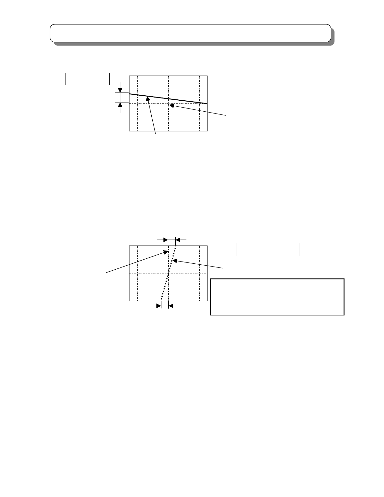
2.14 DIGITAL CONVERGENCE ADJUSTMENT
2.14.1 How to adjust by using remote controller
(1) Receive any PAL signal. (RF or VIDEO)
(2) Turn the set on and set to 100Hz mode.
(3) Push the “SERVICE ONLY” switch on the POWER/DEF P.W.B. to set digital convergence unit of the
adjustment mode.
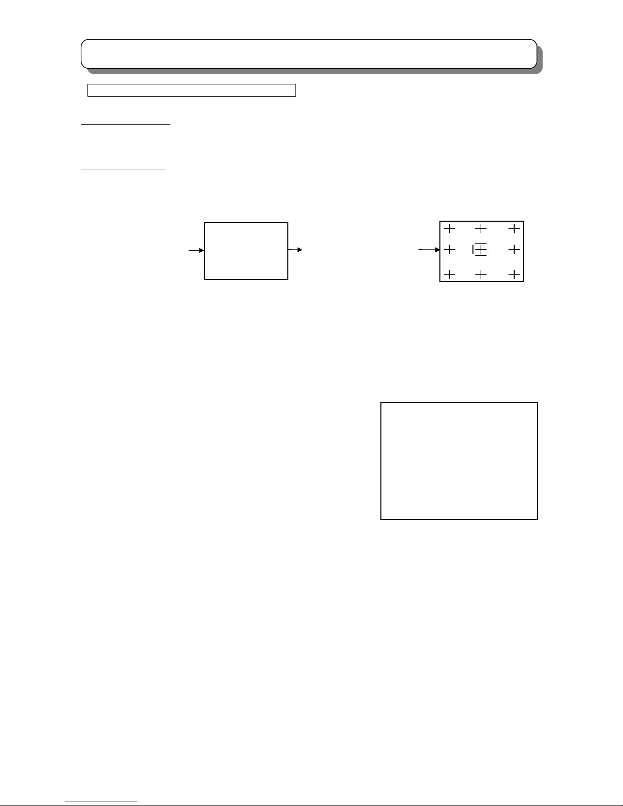
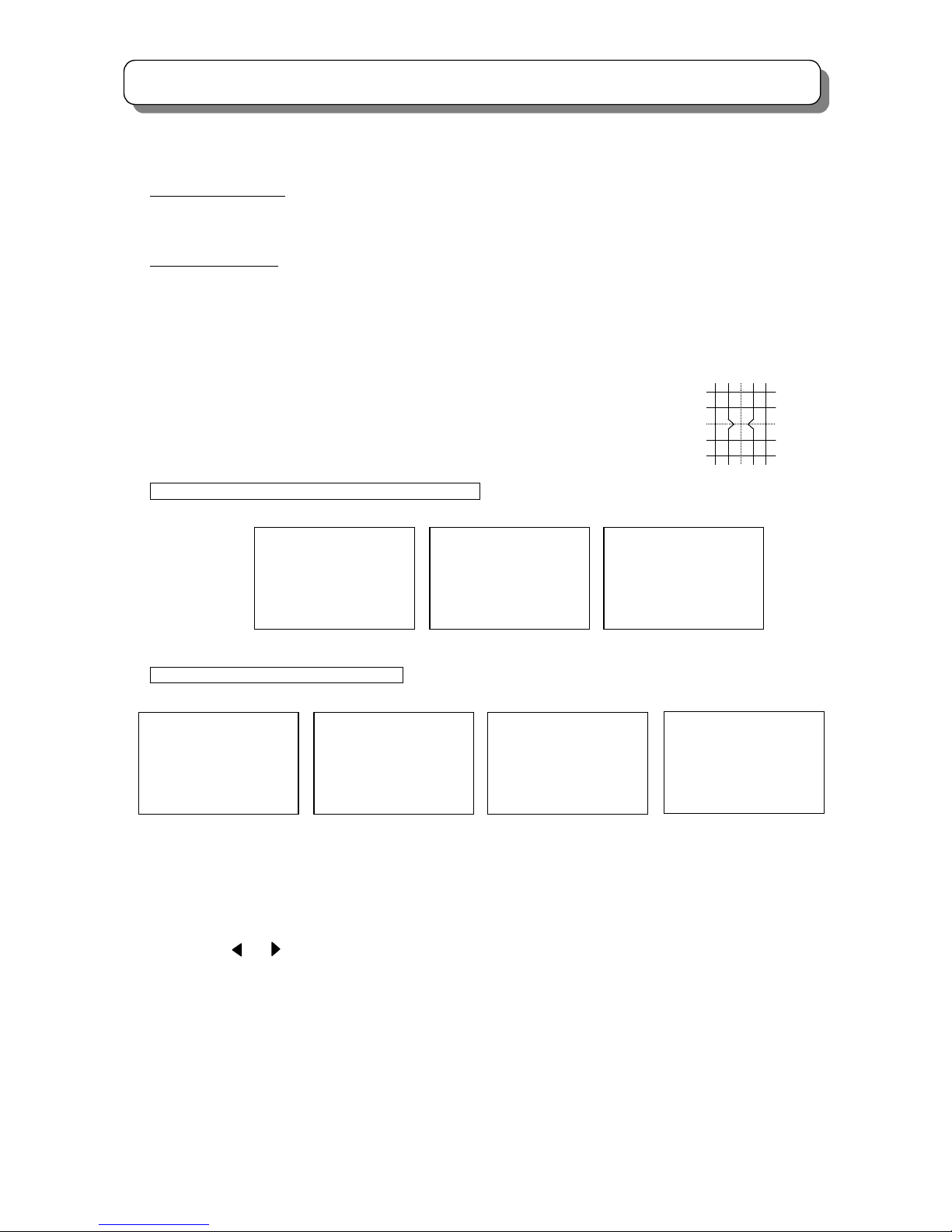
Adjustment point
Adjustment mode
* Adjustment Point Marker ON/OFF
This function can improve view of adjustment point at CONVERGENCE ADJUSTMENT MODE.
a) Press Service Switch on POWER/DEF P.W.B.
to set to CONVERGENCE ADJUSTMENT
MODE, then display Normal Crosshatch WITH
"Adjustment Point Marker". (Fig.3)
b) Press [TV/TEXT] key on R/C, then display only
Normal Crosshatch, WITHOUT "Adjustment
Point Marker". (Fig.4)
Adjustment Point is indicated by broken line
crossing.
c) Press [TV/TEXT] key on R/C again, then
display Normal Crosshatch with "Adjust- ment
Point Marker" again. (Fig.3)
(4) Phase Adjustment
See page 28 DCU PHASE DATA SETTING
Maker is NOT displayed
Fig.3
Adj
ustment Point Marker
Fig.4
A
nd repeat procedure b) ~ c) by each press
[TV/TEXT] key on R/C.
Page 46

46
SERVICE ADJUSTMENTS
(5) Fine adj.
Adjustment points are 117 points.
(H : 13 points x V : 9 points)
ADJ. points can be moved with using
[2], [4], [5], [6] keys.
For better result, adjust convergence
from center to outside of the screen.
(6) Green convergence adj.
Press [▼ / CH down] key on R/C to select green convergence mode.
Adjust each green line using [▲], [▼], [►],[◄] (cursor) key.
(7) Red convergence adj.
Press [0] key on R/C to select red convergence mode.
Adjust each red lines to green cross-hatch line, using [▲], [▼], [►],[◄] (cursor) key.
(8) Blue convergence adj.
Press [▲ / CH up] key on R/C to select Adjustment point blue convergence mode.
Adjust each blue lines to green cross-hatch line, using [▲], [▼], [►],[◄] (cursor) key.
(9) Calculation *
After convergence adjustment is finished, press [MODE] key on R/C, then the calculation mode starts.
The operation time is about for 0.5 seconds. This operation fills convergence data between each
adjustment points.
(10) Write data to ROM
Press [INDEX] key on R/C.
first press: “ROM WRITE?” is displayed for alarm.
2nd press: Data starts to write to ROM, it takes about 3 seconds.
and no picture appears during this operation. If green dot pattern appears, writing operation has
been succeeded. Press [MUTE] key to return to the adjustment mode. If red dot pattern appears,
writing operation has been failed.
Replace digital convergence-unit and readjust.
Push the “SERVICE ONLY” switch again to finish the adjustment.
* In fact, above (9) ‘Calculation’ process by pressing [MODE] key can be omitted,
because (10) ROM WRITE process includes calculation process as well.
ROM WRITE process : ① Calculation process
by pressing [INDEX] key twice. : ② Writing data to ROM
Page 47

47
SERVICE ADJUSTMENTS
(11)
4:3 model
The digital convergence has 3 modes; NTSC 60p, PAL 100i and PAL 50p.
Change the other mode then adjust again (1) ~ (10).
16:9 model
The digital convergence has 4 modes; NTSC 60p, PAL 100i, PAL 50p
and PAL HD. (*) Change the other mode then adjust again (1) ~ (10).
(*)Adjustment Procedure of PAL HD mode.
(a)Receive 1080i(50Hz)
(b)Set the Picture mode to Favorite.
Film mode : Off
Dynamic Contrast : Off
Color Manager : Off
(c)Set Picture Size to 16:9 mode.
NOTES:
(1) [CH Ⅰ/Ⅱ] button
・・・Crosshatch/Video mode
Press [CH Ⅰ/Ⅱ] 5 times to display external signal.
Press [CH Ⅰ/Ⅱ] 5 times again to return to DCU internal cross-hatch.
(2) [MENU] button
・・・Remove color mode
Press [MENU] to switch between all colors displayed or adjustment color and Green only.
✧Press [0], then press [MENU] Red and Green displayed (Blue removed)
✧Press [▲/ CH up], then press [MENU] Blue and Green displayed (Red removed)
✧Press [▼/ CH down], then press [MENU] Only Green displayed
Page 48

48
SERVICE ADJUSTMENTS
* Explanation of "Conv. For Outside Signal" function
1) Press Service Switch on POWER/DEF P.W.B.,
then display "Normal Crosshatch". (Fig.11)
2) Press [MENU] key on R/C,
then display "Red + Green Crosshatch with Red Marker" or
"Green Crosshatch with Green Marker" or "Blue + Green
Crosshatch with Blue Marker". (Fig.12)
3) Press [MENU] key on R/C again,
then display "Normal Crosshatch on Main Picture" (Fig.13)
4) Press [MENU] key on R/C again,
then display "Cross Marker + Box Marker on Main Picture".
(Fig.14)
5) Press [MENU] key on R/C again,
then display "only Box Marker on Main Picture". (Fig.15)
6) Press [MENU] key on R/C again,
then display "Normal Crosshatch" again. (Fig.11)
And repeat procedure 2) ~ 6) by each press [MENU] key on
R/C.
Fig.11
Fig.12
Fig.13
Marker (Adjustment point
)
Marker
Marker
Fig.15 Fig.14
MarkerMarker
Page 49

49
SERVICE ADJUSTMENTS
(3) [SUB] button ・・・Raster position adjustment
Adjustment preparation
(1) Position adjustment ・・・This will move an entire color.
Use this adjustment to match colors at the center of the screen.
(2) Use the buttons below to switch color to adjust.
[▼/ CH down] -Green
[0] -Red
[▲/ CH up] -Blue
Adjustment procedure
(1) Press the [SUB] button. Extra horizontal lines appear to confirm raster position mode.
(2) Use the cursor buttons to adjust position.
(3) Press [SUB] again for exit from raster position mode.
Notes : ① Other functions cannot be accessed during the raster position adjustment mode.
Press [SUB] to exit from raster position mode, and confirm extra horizontal lines are disappeared.
② Press [MENU] to switch between all colors displayed or adjustment color
and Green only.
Page 50

50
SERVICE ADJUSTMENTS
*Convergence Data Adjustment Method
This function can adjust convergence data of all of one line (or all of screen) at the same time, in
CONVERGENCE ADJUSTMENT MODE.
a) Press Service Switch on DEF/CONVER P.W.B. to set to CONVERGENCE ADJUSTMENT MODE,
then display Normal Crosshatch with Adjustment Point Marker. (Fig.16)
b) Press [SUB] key on R/C, then Extra horizontal lines appeared
as set to RATER POSITION ADJUSTMENT MODE. (Fig.17)
ⅰ) If Adjustment Point is on center, by press cursor key
on R/C, then Convergence Data of all of screen are
exchanged at the same time.
ex) Fig.18 (Fig.19) : By press [UP] [LEFT] key on R/C,
move up (left) RED convergence data of all of screen.
ⅱ) If Adjustment Point is NOT
on center, by press cursor
key on R/C, then Convergence Data of all of one line that
Adjustment Point Marker is existing are exchanged at the
same time.
ex) Fig.20 (Fig.21) : By press [UP] [LEFT] key on R/C,
move up (left) RED convergence data of all of
horizontal (vertical) line that Adjustment Point Marker
is existing.
c) Press [SUB] key on
R/C again to exit
RATER POSITION
ADJUSTMENT MODE.
Fig.16
Adj
ustment Point Marker
Fig.19
Fig.21
Fig.18
Fig.20
Fig.17
Extra Horizontal line is added
Convergence Data (RED) of all of screen is exchanged.
Convergence Data (RED) of all of line is exchanged.
Page 51

51
SERVICE ADJUSTMENTS
Adjustment point
Adjustment point
Extra
horizontal line
9 x 13 = 117 point
Adjustment point (NTSC 60p, PAL HD mode)
Adjustment point
Extra
horizontal line
9 x 13 = 117 point
Adjustment point (PAL 50p, PAL 100i mode)
NOTE : PAL mode can be confirmed by extra horizontal lines.
Page 52

52
SERVICE ADJUSTMENTS
Digital convergence remote control
NOTE: 3×3 Adjustment mode can be selected only after DCU uncorrected state.
(DCU uncorrected state: With the Power off, PRESS AND HOLD the Service Only button,
then press the Power On/Off button at the same time until power is applied… Release Both.)
RASTER POSITION
CURSOR LEFT
CURSOR UP
CURSOR DOWN
GREEN
(3x3 ADJ.*)
REMOVE COLOR
INITIALIZE
PHASE
ROM WRITE
ROM READ
CROSSHATCH /
VIDEO MODE
(5 TIMES)
BLUE
(13×9 Fine ADJ.)
RED
(5
×7 ADJ.
)
AV N E T
CLE-959
Page 53

53
SERVICE ADJUSTMENTS
4:3 model NTSC 60p MODE
43” DIGITAL CONVERGENCE CROSSHATCH
50” DIGITAL CONVERGENCE CROSSHATCH
UNIT:mm
876
10.2
10.2
2.0
73.3
83.9
83.9
73.3
2.0
654
71.3
71.3
83.9
71.3 71.3 71.3 71.3 71.3 71.3 71.3 71.3 71.3 71.3
83.9
83.9
83.9
UNIT:mm
1020
12.0
12.0
2.4
85.5
97.7
97.7
85.5
2.4
762
83.0
83.0
97.7
83.0 83.0 83.0 83.0 83.0 83.0 83.0 83.0 83.0 83.0
97.7
97.7
97.7
Specification of digital convergence cross-hatch
Page 54

54
SERVICE ADJUSTMENTS
4:3 model PAL 100i MODE
43” DIGITAL CONVERGENCE CROSSHATCH
50” DIGITAL CONVERGENCE CROSSHATCH
UNIT:mm
876
3.0
3.0
5.0
9.6
78.1
78.19.6
5.0
654
72.5
72.5
72.5 72.5 72.5 72.5 72.5 72.5 72.5 72.5 72.5 72.5
78.1
78.1
78.1
78.1
78.1
78.1
UNIT:mm
1020
3.6
3.6
5.8
11.2
91.0
91.0
11.2
5.8
762
84.4
84.4
84.4 84.4 84.4 84.4 84.4 84.4 84.4 84.4 84.4 84.4
91.0
91.0
91.0
91.0
91.0
91.0
Page 55

55
SERVICE ADJUSTMENTS
4:3 model PAL 50p MODE
43” DIGITAL CONVERGENCE CROSSHATCH
50” DIGITAL CONVERGENCE CROSSHATCH
UNIT:mm
876
3.0
3.0
5.0
9.6
78.1
78.1
9.6
5.0
654
72.5
72.5
72.5 72.5 72.5 72.5 72.5 72.5 72.5 72.5 72.5 72.5
78.1
78.1
78.1
78.1
78.1
78.1
1020
3.6
3.6
5.8
11.2
91.0
91.0
11.2
5.8
762
84.4
84.4
84.4 84.4 84.4 84.4 84.4 84.4 84.4 84.4 84.4 84.4
91.0
91.0
91.0
91.0
91.0
91.0
UNIT
:mm
Same as PAL100i MODE
Same as PAL100i MODE
Page 56

56
SERVICE ADJUSTMENTS
16:9 model NTSC 60p MODE
47” DIGITAL CONVERGENCE CROSSHATCH
57” DIGITAL CONVERGENCE CROSSHATCH
UNIT:mm
1040
16.0
16.0
28.4
37.7
75.3
75.3
37.7
28.4
584
84.0
84.0
75.3
84.0 84.0 84.0 84.0 84.0 84.0 84.0 84.0 84.0 84.0
75.3
75.3
75.3
UNIT:mm
1262
20.2
20.2
34.1
45.8
91.7
91.7
45.8
34.1
710
101.8
101.8
91.7
101.8 101.8 101.8 101.8 101.8 101.8 101.8 101.8 101.8 101.8
91.7
91.7
91.7
Page 57

57
SERVICE ADJUSTMENTS
16:9 model PAL 100i MODE
47” DIGITAL CONVERGENCE CROSSHATCH
57” DIGITAL CONVERGENCE CROSSHATCH
UNIT:mm
1262
5.2
5.2
5.2
10.6
84.8
84.8
10.6
5.2
710
93.3
93.3
84.8
106.5 106.5 106.5 106.5 106.5 106.5 106.5 106.5 106.5 106.5
84.8
84.8
84.8
84.8
84.8
UNIT:mm
1040
4.2
4.2
4.1
8.7
69.8
69.8
8.7
4.1
584
76.8
76.8
69.8
87.8 87.8 87.8 87.8 87.8 87.8 87.8 87.8 87.8 87.8
69.8
69.8
69.8
69.8
69.8
Page 58

58
SERVICE ADJUSTMENTS
16:9 model PAL 50p MODE
47” DIGITAL CONVERGENCE CROSSHATCH
57” DIGITAL CONVERGENCE CROSSHATCH
UNIT:mm
1040
4.2
4.2
4.1
8.7
69.8
69.8
8.7
4.1
584
76.8
76.8
69.8
87.8 87.8 87.8 87.8 87.8 87.8 87.8 87.8 87.8 87.8
69.8
69.8
69.8
69.8
69.8
UNIT:m
m
1262
5.2
5.2
5.2
10.6
84.8
84.8
10.6
5.2
710
93.3
93.3
84.
8
106.5 106.5 106.5 106.5 106.5 106.5 106.5 106.5 106.5 106.5
84.8
84.8
84.8
84.8
84.8
Same as PAL100i MOD
E
Same as PAL100i MODE
Page 59

59
SERVICE ADJUSTMENTS
16:9 model PAL HD MODE
47” DIGITAL CONVERGENCE CROSSHATCH
57” DIGITAL CONVERGENCE CROSSHATCH
UNIT:mm
1040
9.7
9.7
28.4
37.7
75.3
75.3
37.7
28.4
584
24.3
24.3
75.3
97.2 97.2 97.2 97.2 97.2 97.2 97.2 97.2 97.2 97.2
75.3
75.3
75.3
UNIT:mm
1262
12.0
12.0
34.145.8
91.7
91.7
45.8
34.1
710
29.5
29.5
91.7
117.9 117.9 117.9 117.9 117.9 117.9 117.9 117.9 117.9 117.9
91.7
91.7
91.7
Page 60

60
SERVICE ADJUSTMENTS
2.14.2 Scanning area check
Checking condition
(1) Digital convergence adjustment should be completed.
(2) Receive the Hitachi circle pattern signal.
(3) Contrast and Brightness should be set Factory Preset condition
Contrast : max
Other controls : Center position
(4) Check that the scanning area matches with the next drawing.
(5) The digital convergence has 3 modes. Change the other mode then check again.
(6) Check the horizontal center position. If the center is shifted, readjust to center position.
*Service menu No.68 : Horizontal position for PAL 100i mode.
No.69 : Horizontal position for PAL 50p mode.
No.70 : Horizontal position for NTSC 60p mode.
No.71 : Horizontal position for 1080i(50Hz) mode. (*)
No.72 : Horizontal position for 1080i(60Hz) mode. (**)
(*)Setting Procedure.
(a)Receive 1080i(50Hz)
(b)Set the Picture mode to Favorite.
Film mode : Off
Dynamic Contrast : Off
Color Manager : Off
(c)Set Picture Size to 16:9 mode.
(**) Setting Procedure.
(a)Receive 1080i(60Hz)
(b)Set the Picture mode to Favorite.
Film mode : Off
Dynamic Contrast : Off
Color Manager : Off
(c)Set Picture Size to 16:9 mode.
Page 61

61
SERVICE ADJUSTMENTS
PAL 100i / PAL 50p / NTSC MODE
Inner edge of the
H size marker
0.7~1.5
Outer edge of the
H size marker
0.7~1.5
Top and bottom of the circle is between outer edge and inner edge.
Page 62

62
SERVICE ADJUSTMENTS
2.15 BLUE DEFOCUS ADJUSTMENT
Preparation for adjustment
(1) Optical and electrical focus adjustment should be completed.
(2) The convergence adjustment should be completed.
(3)VIDEO control should be set Factory Preset condition.
Contrast : Max.
other items : Center
Adjustment procedure
(1) Input Cross-hatch signal to VIDEO or RF input.
(2) Turn the B FOCUS VR fully clockwise.
(3) Adjust sticking out level of Blue as the spec of below table with turning the FOCUS VR counterclockwise.
BLUE DEFOCUS
CHASSIS DP4M UNIT
SCREEN SIZE 43” 47” 50” 57” INCH
STICKKING OUT 1.5 1.5 1.5 1.5 mm
Sticking out of blue
Note: The view point should be limited to the center of the screen for this adjustment. (FOB 0.0)
Page 63

63
SERVICE ADJUSTMENTS
2.16 WHITE BALANCE ADJUSTMENT
2.16.1 CHECK CUT OFF ADJUSTMENT
Adjustment preparation
Pre heat-run should be finished.
Adjustment procedure
(1) Go to “SERVICE item No10” and press [►] key to enter CUT OFF adjustment mode by using JIG R/C.
(2) Check the each line is just appearing.
(3) If some of line is/are brighter/darker than others, apply CUT OFF ADJUSTMENT again.
(4) Press [◄] key to return to normal mode.
2.16.2 WHITE BALANCE ADJUSTMENT
High brightness white balance
Service Item Item No.
Red : (R DRV) 43
Green: (G DRV) 44
Adjustment preparation
(1) Pre-heat 20 minutes or more before the adjustment.
(2) VIDEO control should be set Factory Preset condition.
(Contrast : MAX., others : center)
(3) Color temp. : COOL
(4) Signal (COMPONENT INPUT should be used in order to reduced digital noise.)
SIGNAL
High Light white balance ADJ WHOLE WHITE 100 IRE
Low Light white balance ADJ WHOLE WHITE 25 IRE
* Use signal without color burst. If it is not possible, use PAL signal and turn off comb filter in User Menu.
(5) BLUE defocus ADJ. should be finished.
(6) The vertical incident illumination on the screen should be 20 Lux. or less.
Adjustment procedure
A) High Light W/B adjustment:
(1) Receive signal for High Light white balance ADJ.
(2) Adjust the white balance to below Data at the screen
High Light W/B
White Balance Data (x, y) = (0.266, 0.270)
center by using JIG R/C. Use item No. 43(R DRV) to adjust x, item No 44 (G DRV)
to adjust y.
B) Low Light W/B adjustment
(1) Receive signal for Low Light white balance ADJ.
(2) Adjust the white balance to below Data by using R/C
Low Light W/B
White Balance Data (x, y) = (0.266,0.270)
Use item No.45 (R CUT OFF) to adjust x, item No.47 (B CUT OFF) to adjust x AND y.
Do NOT change the item No.46(G CUT OFF) setting.
Repeat A & B two or three times.
Sub Brightness should be adjusted roughly
Before adjust the white balance.
Low brightness white balance
Service Item Item No.
Red : (R cut OFF) 45
Green: (G cut OFF) 46
Blue : (B cut OFF) 47
Page 64

64
SERVICE ADJUSTMENTS
WHITE BALANCE ADJUSTMENT FLOWCHART
FINISH
Cutoff Adj
BLUE defocus Adj
If Bluish
Check
Low light W/B
A
djust Low light W/B
A
djust High light W/B
Sub bright Adj
START
Repeat two or three times, until
no adjustment is needed
Check
Low light W/B
High light W/B
NG
OK
Sub Brightness Adj
Page 65

65
SERVICE ADJUSTMENTS
2.17 SUB BRIGHTNESS ADJUSTMENT
Adjustment preparation
(1) Pre-heat 20 minutes or more before the adjustment.
(2) Receive the color bar signal.
(3) The vertical incident illumination on the screen should be 20 lux or less.
Adjustment procedure
(1) Go to “Sub Brightness (item No 37)” adj. mode by using JIG R/C.
(2) Adjust Sub brightness as following spec. by using JIG. R/C.
(3) Press “ENTER” key on R/C to write the data.
REMARKS
Observe the TV SET screen directly by eyes; do not use a mirror.
Adjustment specification : Within ±0.3 step
Quality control specification : Within ±0.5 step
* Note: During the SUB-BRIGHTNESS adjustment mode, TV µcon changes the CONTRAST and the
COLOR controls to Min., but the other controls are not changed automatically.
Make sure that the other controls are set center.
Note: Actual procedure;
(1)Once A1 is set to black and is seen as dark as A0 (the level that the border of the two cannot be identified),
Note: Actual procedure, set A1 portion to black (same level as A0 portion) and reduce 4 steps to set A1 portion
slightly brighter.
Sink to black Slightly for black
DP4M
(A0) (A1)
A
0 A1 A2 A3 A4 A5 A6 A7 A8 A9 A10
Page 66

66
SERVICE ADJUSTMENTS
2.18 SUB PICTURE ADJUSTMENT
Adjustment procedure
(1) Display sub Picture on the screen.
Receive SYSTEM B.G Phillips pattern in Main picture
Receive SYSTEM D.K Phillips pattern in Sub picture
(2) Observe P852 on the CPT P.W.B. and change the SUB CONTRAST (Item No. 59) of service mode
by using jig R/C and adjust so that the amplitude of the sub-picture is the same as that of the
main-picture.
(3) Press “ENTER” key to write the data.
* Adjustment specification : ±1V
* Quality control specification : ±3V
* Wave form of P852 = Cathode
(Sub picture level compared with main picture level)
* Perform this adjustment after the white balance and sub-brightness adjustments of the main
picture are completed.
* White balance 14000K±0 MPCD
(Color coordinates: x=0.266 y=0.270)
1H
CATHODE WAVE FORM
WHITE
(
CATHODE VOLTAGE)
MAIN PICTURE
Page 67

67
SERVICE ADJUSTMENTS
2.19 TINT ADJUSTMENT
(1) PREPARATION
Pre heat-run should be finished.
(2) Input A NTSC window pattern signal like below to the AV3 and AV4.
(3) Enter to split mode and display AV3 and AV4;
(4) Enter to service mode;
(5) Observe “B” cathode and adjust the INT level and EXT level by item No.62 FOR MAIN(RIGHT), item No.63
for SUB(LEFT)
DO NOT FORGET TO PRESS ENTER TO SAVE THE RESULT.
1/2
1/2
INT Y = 0%
EXT Y = 0%
INT C = 100%
EXT C = 100%
INT C = - 90°
EXT C = + 90°
Page 68

68
SERVICE ADJUSTMENTS
2.20 MAGIC FOCUS INITIALIZE
2.20.1 MAGIC FOCUS INITIALIZE
Adjustment preparation
(1) Receive the PAL cross-hatch or PAL circle pattern signal and set 100i mode.
(2) Digital convergence adjustment should be completed.
Adjustment procedure
(1) Press ”SERVICE ONLY” SW on DEF/CONVER P.W.B. to set DCU the adjustment mode.
(2) Press [INDEX] key on R/C. Then “ROM WRITE ?” message is displayed to confirm the ROM writing.
(3) Press [RECALL] key on R/C to cancel the ROM writing and start initialization.
It takes about 45 seconds by green dots appear after initialization is completed.
(4) Check that green dots appear.
(5) Turn the power switch off.
(6) Change the PAL 50p mode and repeat the procedure (1) ~ (5) for PAL50p mode.
(7) Change the signal to NTSC circle pattern and repeat the procedure (1)-(5) for the NTSC 60p mode.
(8) [16:9 model only] Change the signal to PAL HD circle pattern and repeat the procedure (1)-(5) for the PAL
HD mode.
Initialize operation
OSD:
PAL 100i mode *INITIAL:1*
PAL HD mode *INITIAL:2*
PAL 50P mode *INITIAL:5*
NTSC 60P mode *INITIAL:6*
NOTE:
4:3 model
The digital convergence has 3 modes NTSC 60p, PAL 100i and PAL 50p.
Therefore this adjustment needs 3 modes.
16:9 model
The digital convergence has 4 modes NTSC 60p, PAL 100i, PAL 50p and PAL HD.
Therefore this adjustment needs 4 modes.
(9)
Note : If any error message (red) appears, refer to 2.20.2 CONVERGENCE ERRORS.
*INITIAL:6*
Page 69

69
SERVICE ADJUSTMENTS
2.20.2 CONVERGENCE ERRORS
If there is an error while performing INITIALIZE or MAGIC FOCUS, error code or message appears on the screen
as table below.
When MAGIC FOCUS operates: Error code (GREEN) appears for about 1 second at bottom right corner, and
soon it returns to RF or video signal.
When INITIALIZE operates: Error message (RED) appears all the time.
Error Error Contents Countermeasure / Check method
Code Massage
1 VF ERROR ! EEPROM Write Error Replace the DCU
2 CONNECT1 ! Connection Check Error Darken outside light
No.01234567 (Pattern is not detected) Check the placement of the sensor
OVER FLOW ! Is pattern hitting to sensor?
No.01234567 Check connection and solder bridge of
*1 sensor
3 A/D LEVEL ! Calibration Error Replace the sensor
No.01234567 (Small difference between Check Sensor connector
OVER FLOW ! High and Low brightness) Check Sensor PWB
No.01234567 Adjustment check
*1 (H/V size, centering)
4 OVER FLOW ! Data Over Flow Error Check the placement of the sensor
(Saturation of corr. Data) Adjustment check
5 CONVERGENCE! Convergence Error (H/V size, centering)
(The number of ADJ. Times Conv. AMP circuit check
is more than setting.)
6 LOOP COUNT ! Not Used
7 OPERATION ! Make Setup Data Error Same as error code 4
8 CHECK SUM ! Different SRAM-EEPROM Replace the DCU
9 CONNECT2 ! Connect Data Set Error Same as error code 2
No.01234567 (ADJ. Parameter PORT80-87
*1 is wrong setting)
10 NOISE ! Sensor Noise Error Input strong field strength signal.
Check the wiring dress of connector
between sensor and DCU.
11 SYNC ! H BLK, V BLK Error Input strong field strength signal.
Input standard signal NTSC or PAL.
REMARKS *1) Relation of sensor No. and screen position as shown below.
On screen
(View from front side) sensor No. 0-7
6 5 4
0 1 2
7 3
Page 70

70
SERVICE ADJUSTMENTS
3.1 PRT CABINET LOCATIONS
FRONT
3.2 FOCUS PACK
(4) 4-POLE MAGNET FOR BEAM FORM ADJUSTMENT
(5) BEAM ALIGNMENT MAGNET
(6) FOCUS PACK
(1) CENTERING MAGNET FOR RED PRT
(2) CENTERING MAGNET FOR GREEN PRT
(3) CENTERING MAGNET FOR BLUE PRT
R G B
FOCUS PACK
SCREEN GREEN
SCREEN BLUE
FOCUS BLUE
SCREEN RED
FOCUS GREEN
FOCUS RED
1 4 3
2
5
46
5
Page 71

71
SERVICE ADJUSTMENTS
3.3 MAIN P.W.B.
SIGNAL BLOCK ASY
IY04
0
FC
Unit
UY01
PSC
PFH1
PSRT
PJIG
PJIG2
PFS1
PFH2
PPCS XARP
PFS2
Signal SUB PWB
PBS2
ZH-11V
Tuner
U301/U302
TUNER PWB
EH2P
EH2P
0
240
0
325
240
0
325
Page 72

72
SERVICE ADJUSTMENTS
SIGNAL SUB P.W.B
IG02
IG03
IG04
IQ01
IQ02
IR01
Rear view
IG01
IR02
Page 73

73
SERVICE ADJUSTMENTS
CPT P.W.B.
P852
(Cathode)
P851
E851
GND
GREEN
P802
(Cathode)
P801
E801
GND
RED
P8A1
E8
A
1
GND
BLUE
3 1 3 1
3 1
P8A2
(Cathode)
Page 74

74
SERVICE ADJUSTMENTS
CONTROL P.W.B.
LED P.W.B.
MENU
TV/VIDEO
V
OL-DOWN
CH-UP
V
OL-UP
CH-DOWN
PPL1
IR RECEIVER
POWER LED(BLUE)
PFS
BLUE LED
PHOTO MC LED(GREEN)
PCC1 PFI1
PLL2
N
ote: only for model
C47/C57-WD7000
N
ote: C43-FL7000 hasn’t the LED P.W.B
Page 75

75
SERVICE ADJUSTMENTS
AV INPUT P.W.B.
AC SW P.W.B
. IR-AV NET P.W.B.
INPUT 5
S
PFH PFT1
LR V
MAGIC
ECC1
PFN
POWER SW
PCIA
PCIB
PFT1
IR RFECEIVER
For AV NET
N
ote: Only for
model C47/C57-WD7000
(
only for model C47/C57-WD7000
C43/C50-FD7000)
Page 76

76
SERVICE ADJUSTMENTS
DP4M POW/DEF P.W.B.
I601
PDSE
FP01
FUSE
DP40
+B
IP02
FB
DP50
+28V
EP02
+B
PSN
Back Cover Side
PDS1 PDS2
PDS3
CP04 CP03
PADJ
DIGITAL
CONVERGENCE
UNIT
TP01
QP01
DP30
CH16
QP02
EK01
+7V
PDCU
QK01
IK01
QH01
Q777
Q701
DP01
TH02
PDF1
PDD1
PPDC
PPDE
EP01
+28V
PDC1
SK01
Page 77

77
SERVICE MENU
ADJUSTMENT PROCEDURE
(1) Receive signal on main picture, then turn off the main power.
(2) Press and hold the [TV/VIDEO] button on Control Panel and then
Power ON to access service adjustment mode. (Hold the [TV/VIDEO]
button until service menu appears.)
(3) Adjust required items by the following table. Select item by [▲] o
r
[▼] button on remote handset and adjust by [►] or [◄] button.
(4) Press [ENTER] button to memorize the value
ADJUSTMENT DETAILS
No.
ITEM MODE
ADJ.
RANGE
INITIAL
DATA
IC
0 CH_PRESET - 0~2 0 -
1 Model Identification 1:ASPECT - 0~1 0 -
2 Model Identification 2:Destination - 0~1 0 -
3 Model Identification 3:LIGHT - 0~1 0 -
4 Model Identification 4:Multi Picture - 0~2 0 -
5 Model Identification 5:Color Manager - 0~2 0 -
6 Model Identification 6:PC - 0~5 0 -
7 Model Identification 7:IR_BRASTER - 0~8 0 -
8 Model Identification 8:MC - 0~1 0 -
9 Model Identification 9:HD - 0~1 0 -
10 CUT_OFF ADJ. - 0~1 0 -
11 AGC ADJ. MAIN 0~255 75 CXA1875
12 AGC ADJ. SUB 0~255 120 CXA1875
13 V_SIZE Deflection Mode 1 0~127 38 TA1317AN
14 H_SIZE Deflection Mode 1 0~127 53 TA1317AN
15 Parabola Modification Deflection Mode 1 0~63 25 TA1317AN
16 Side Pin Symmetry Modification Deflection Mode 1 0~127 66 TA1317AN
17 V SIZE Deflection Mode 2 0~127 24 TA1317AN
18 H SIZE Deflection Mode 2 0~127 53 TA1317AN
19 Parabola Modification Deflection Mode 2 0~63 26 TA1317AN
20 Side Pin Symmetry Modification Deflection Mode 2 0~127 65 TA1317AN
21 V SIZE Deflection Mode 3/5 0~127 23 TA1317AN
22 H SIZE Deflection Mode 3/5 0~127 23 TA1317AN
23 Parabola Modification Deflection Mode 3/5 0~63 24 TA1317AN
24 Side Pin Symmetry Modification Deflection Mode 3/5 0~127 62 TA1317AN
25 V SIZE Deflection Mode 4 0~127 0 TA1317AN
26 H SIZE Deflection Mode 4 0~127 6 TA1317AN
27 Parabola Modification Deflection Mode 4 0~63 20 TA1317AN
28 Side Pin Symmetry Modification Deflection Mode 4 0~127 47 TA1317AN
43 R_DRIVE COOL 0~127 63 TA1360AN
44 G_DRIVE COOL 0~127 63 TA1360AN
45 R_CUT_OFF COOL 0~255 127 TA1360AN
46 G_CUT_OFF COOL 0~255 127 TA1360AN
47 B_CUT_OFF COOL 0~255 127 TA1360AN
59 SUB_CONTRAST SUB 0~15 10 TB1274
62 TINT MAIN 0~15 32 TB1274
63 TINT SUB 0~63 32 TB1274
68 HORIZONTAL_POSITION Deflection Mode 1 0~63 78 TA1360AN
69 HORIZONTAL_POSITION Deflection Mode 2 0~127 77 TA1360AN
70 HORIZONTAL_POSITION Deflection Mode 3 0~127 66 TA1360AN
71 HORIZONTAL_POSITION Deflection Mode 4 0~127 71 TA1360AN
72 HORIZONTAL_POSITION Deflection Mode 5 0~127 71 TA1360AN
627 MEMORY_INITIAL3(ADJUST) INIT3 (ADJUST/MODEL SETUP) - - -
628 SHIPMENT1(USER) SHIP1(USER MENU/CH/MODEL SETUP) - - -
629 SHIPMENT2(USER-EXCEPT_PRESET) SHIP2(USER MENU) - - -
630 MEMORY_INITIAL2(ALL) INIT2(ALL) - - -
V
ersion: V202
Below items are for service
adjustment (Don’t change othe
r
items except for below.)
DEFLECTION MODE
Deflection Mode1 Fh=31.25kHz, fv=100Hz, FC=pass
Deflection Mode2 Fh=31.25kHz, fv= 50Hz, FC=pass
Deflection Mode3 Fh=33.75kHz, fv= 60Hz, FC=pass
Deflection Mode4 Fh=28.125kHz, fv= 50Hz, FC=bypass
Deflection Mode5 Fh=33.75kHz, fv= 60Hz, FC=bypass
Page 78

78
EXPLODED VIEW
Page 79

79
EXPLODED VIEW
Page 80

80
REPLACEMENT PARTS LIST
PRODUCT SAFETY NOTE: Components marked with a have special characteristics important to safety. Before
replacing any of these components, read carefully the PRODUCT SAFETY NOTICE of this Service Manual. Don’t
degrade the safety of the receiver through improper servicing.
NOTE: Below are parts used in C47-WD7000.
ITEM
NO.
PART NO DESCRIPTION
ITEM
NO.
PART NO DESCRIPTION
C47-WD7000 Explode view
1
NT03722A 47B FRAME ASS
17
MF01201A 47B/57B PRT SEALED BOARD
2
KR02743 FRONT SHEET
18
UE24161A DP4M_TOP CONTROL ASS ASS
3
KR03285 FRESNEL SHEET
19
PH35303A 47B SPEAKER GRILL ASS
4
NT03271A MIRROR HOLDER (L)
20
-
5
NA63841A MIRROR METAL TOP
21
UE24251A DP4M_TOP AV ASS
6
KS08492A 47B_AL SURFACE MIRROR
22
UE21475 HSA LENS LABEL ASY(H/G)
7
QD39401A 47B COVER ASS
23
UE21476 HSA LENS LABEL ASY(H/B)
8
6231431A MIRROR METAL BOTTOM
24
UE24071 HSA-MAB LCB ASY(R)
9
NT03272A MIRROR HOLDER (R)
25
UE24072 HSA-MAB LCB ASY(G)
10
QG01991A 47B BOTTOM B/C ASS (C)
26
UE24073 HSA-MAB LCB ASY(B)
11
QG02031A 47B BOTTOM B/C ASS(R)
27
NA73351A 47B LENS CRT METAL ASS
12
QG01951A 47B BOTTOM ASS
28
4527821A M6 BOLT WITH WASER
13
QG02032A 47B BOTTOM B/C ASS(L)
29
4524916A HEXAGON FLANGEHEAD
14
GK01291 SP-13CM C130RB503-10
30
4524911A HEXAGON FLANGEHEAD
15
GK00911 SP-5CM C057FT511-10
31
UE21474 HSA LENS LABEL ASY(H/R)
16
-
NOTE: Below are parts used in C57-WD7000.
ITEM
NO.
PART NO DESCRIPTION
ITEM
NO.
PART NO DESCRIPTION
C57-WD7000 Explode view
1
NT03732A CMT57A FRAME ASS
17
MF01201A 47B/57B PRT SEALED BOARD
2
KR02496 FRONT SHEET
18
UE24161A DP4M_TOP CONTROL ASSASS
3
KR03286 FRESNEL SHEET
19
PH35291A 57B SPEAKER GRIL ASS
4
NT03271A MIRROR HOLDER (L)
20
-
5
NA63841A MIRROR METAL TOP
21
UE24251A DP4M_TOP AV ASS
6
KS08494A 57B_AL SURFACE MIRROR
22
KQ03081K HSB LENS SASS RG
7
QD39391A 57B(DP4M) MIRROR COVER
23
KQ03082K HSB LENS SASS B
8
NA73101A MIRROR METAL BOTTOM 24
UE24081 HSB-MAB LCB ASY(R)
9
NT03272A MIRROR HOLDER (R)
25
UE24082 HSB-MAB LCB ASY(G)
10
QG02001A 57B BOTTOM B/C ASS (C) 26
UE24083 HSB-MAB LCB ASY(B)
11
QG02041A 57B BOTTOM B/C ASS(R)
27
NA73381A
57B LENS CRT METAL ASS
12
QG01961A 57B BOTTOM ASS
28
4527821A M6 BOLT WITH WASER
13
QG02042A 57B BOTTOM B/C ASS(L)
29
4524916A HEXAGON FLANGEHEAD
14
GK01291 SP-13CM C130RB503-10
30
4524911A HEXAGON FLANGEHEAD
15
GK00911 SP-5CM C057FT511-10
31
KQ03081K HSB LENS SASS RG
16
-
NOTE: Below are parts used in C43-FD7000.
ITEM
NO.
PART NO DESCRIPTION
ITEM
NO.
PART NO DESCRIPTION
C43-FD7000 Explode view
1
NT03501A CMT43800H FRAME ASS
17
-
2
KR01324 FRONT SHEET
18
UE24162A DP4M_HIGH CONTROL ASS
3
KR01335 FRESNEL SHEET
19
UX23273A C43-FD7000 SPEAKER GRILL ASS
Page 81

81
REPLACEMENT PARTS LIST
ITEM
NO.
PART NO DESCRIPTION
ITEM
NO.
PART NO DESCRIPTION
4
NT03271A 47 MIR.HOLDER<L>
20
-
5
NA67271A 43H MIRROR SUPPORT(UP)
21
UE24252A DP4M_HI_MID SIDE AV ASS
6
KS08491A 43_DP4M MIRROR
22
UE21475A HSA LENS LABEL ASY(H/G)
7
QD39381A 43_DP4M BACK COVER ASS
23
UE21476A HSA LENS LABEL ASY(H/B)
8
NA73091A 43 MIRROR METAL LOW
24
UE22874A HAS-LXL C LENS CRT B.ASY (R)
9
NT03272A 47 MIR.HOLDER<R>
25
UE22875A HAS-LXL C LENS CRT B.ASY (G)
10
QG01971A 43_DP4M BOTTOM COVER) ASS
26
UE22876A HAS-LXL C LENS CRT B.ASY (B)
11
QG02012A 43_DP4M SIDE COVER ASS(L)
27
6211062A 43 HSA PRT METAL ASS
12
QG01931A CMT43900H BOTTOM ASS
28
4527821A M6 BOLT WITH WASER
13
QG02011A 43_DP4M SIDE COVER ASS(R)
29
4524916A HEXAGON FLANGEHEAD
14
GK01241 SP-12CM C120RB512-10
30
4524911A HEXAGON FLANGEHEAD
15
GK01251 SP-5CM C057FT511-11
31
UE21474A HSA LENS LABEL ASY(H/R)
16
-
NOTE: Below are parts used in C50-FD7000.
ITEM
NO.
PART NO DESCRIPTION
ITEM
NO.
PART NO DESCRIPTION
C50-FD7000 Explode view
1
NT04601A CMT50900H FRAME ASS
17
-
2
KR02762 FRONT SHT FINE 50
18
UE24162A DP4M(HIGH) CONTROL PANET ASS
3
KR03295 FRSNL 50HSA NEWUV
19
UX23522A 50890H SPEAKER GRILL ASS
4
NT03271A 47 MIR.HOLDER<L>
20
-
5
NA63841A MIRROR METAL TOP
21
UE24252A DP4M_HI_MID SIDE AV ASS
6
KS08493A 50B_AL SURFACE MIRROR
22
UE21475A HSA LENS LABEL ASY(H/G)
7
QD39101A 50B MIRROR COVER
23
UE21476A HSA LENS LABEL ASY(H/B)
8
NA73101A MIRROR METAL BOTTOM
24
UE22874A HAS-LXL C LENS CRT B.ASY (R)
9
NT03272A 47 MIR.HOLDER<R>
25
UE22875A HAS-LXL C LENS CRT B.ASY (G)
10
QG01981A 50B LOW COV ASS
26
UE22876A HAS-LXL C LENS CRT B.ASY (B)
11
QG02021A 50B BOTTOM B/C ASS(R)
27
NA73352A 57B LENS CRT METAL ASS
12
QG01941A 50B BOTTOM ASS
28
4527821A M6 BOLT WITH WASER
13
QG02022A 50B BOTTOM B/C ASS(L)
29
4524916A HEXAGON FLANGEHEAD
14
GK01241 SP-12CM C120RB512-10
30
4524911A HEXAGON FLANGEHEAD
15
GK01251 SP-5CM C057FT511-11
31
UE21474A HSA LENS LABEL ASY(H/R)
16
-
NOTE: Below are parts used in C43-FL7000.
ITEM
NO.
PART NO DESCRIPTION
ITEM
NO.
PART NO DESCRIPTION
C43-FL7000 Explode view
1
NT04611A 43_DP4M_LEADER FRAME ASS
17
-
2
KR01324 FRONT SHEET
18
UE24162A DP4M_HIGH CONTROL ASS
3
KR01335 FRESNEL SHEET
19
UX23273A C43-FD7000 SPEAKER GRILL ASS
4
NT03271A 47 MIR.HOLDER<L>
20
-
5
NA67271A 43H MIRROR SUPPORT(UP)
21
UE24253A DP4M_LEADER SIDE AV ASS
6
KS08491A 43_DP4M MIRROR
22
UE21475A HSA LENS LABEL ASY(H/G)
7
QD39381A 43_DP4M BACK COVER ASS
23
UE21476A HSA LENS LABEL ASY(H/B)
8
NA73091A 43 MIRROR METAL LOW
24
UE22874A HAS-LXL C LENS CRT B.ASY (R)
9
NT03272A 47 MIR.HOLDER<R>
25
UE22875A HAS-LXL C LENS CRT B.ASY (G)
10
QG01971A 43_DP4M BOTTOM COVER) ASS
26
UE22876A HAS-LXL C LENS CRT B.ASY (B)
11
QG02012A 43_DP4M SIDE COVER ASS(L)
27
6211062A 43 HSA PRT METAL ASS
12
QG01931A CMT43900H BOTTOM ASS
28
4527821A M6 BOLT WITH WASER
13
QG02011A 43_DP4M SIDE COVER ASS(R)
29
4524916A HEXAGON FLANGEHEAD
14
GK01241 SP-12CM C120RB512-10
30
4524911A HEXAGON FLANGEHEAD
15
GK01251 SP-5CM C057FT511-11
31
UE21474A HSA LENS LABEL ASY(H/R)
16
-
Page 82

82
REPLACEMENT PARTS LIST
PRODUCT SAFETY NOTE: Components marked with a have special characteristics important to safety. Before
replacing any of these components, read carefully the PRODUCT SAFETY NOTICE of this Service Manual. Don’t
degrade the safety of the receiver through improper servicing.
ABBREVIATIONS
Capacitors…………… CD: Ceramic, PF: Polyester film, EL: Electrolytic,
PP: Polypropylene, PR: Paper, TA: Tantalum, TM: Trimmer,
MYL: Mylar
Resistors…………….. CF: Carbon film, CC: Carbon composition,
MF: Metal oxide film, VR: Variable, WW: Wire wound,
FR: Fuse resistor, MG: Metal glazed
Semiconductors…….. TR: Transistor, DI: Diode, ZD: Zener diode, VA: Varistor,
TH: Thermistor, IC: IC
SYMBOL NO.DESCRIPTION
SYMBOL NO. SUFFIX PART LOCATION
-5 CPT PWB/CONTROL PWB
-20 TUNER PWB
-2 POWER/DEFLECTION PWB
-3 SIGNAL SUB PWB
-1 SIGNAL PWB
-9 CONVERGENCE/FOCUS PWB
OTHERS Other Units
ABOUT POWER CORD (E901):
SYMBOL NO. PART NO. DESCRIPTION FOR CODE
E999 7068372A CEE POWER CORD 081, 433, 192
E999 EV01461 POWER CORD 751
P.W.B ASS’Y ORDER NO.
P.W.B ASS’Y NO.
PWB NAME
C47-WD7000 C57-WD7000 C43-FD7000 C50-FD7000 C43-FL7000
CPT PWB/CONTROL PWB ASS
JT24876A JT24877A JT24737A JT24864A JT24738A
TUNER PWB ASS
JT24796A JT24797A JT24697A JT24784A JT24698A
POWER/DEFLECTION PWB ASS
JT24836A JT24837A JT24717A JT24824A JT24718A
SIGNAL SUB PWB ASS
JT24816A JT24817A JT24707A JT24804A JT24708A
SIGNAL PWB ASS
JT24776A JT24777A JT24687A JT24764A JT24688A
CONVERGENCE/FOCUS PWB ASS
JT24856A JT24857A JT24727A JT24844A JT24728A
Page 83

REPLACEMENT PARTS LIST
PART NO. DESCRIPTION PART NO. DESCRIPTION PART NO. DESCRIPTION PART NO. DESCRIPTION PART NO. DESCRIPTION
CPT P.W.B / CONTROL P.W.B
A-5 JT24876A C47-WD7000 CPT/VM PWB ASS JT24877A C57-WD7000 CPT/VM PWB ASS JT24737A C43-FD7000 CPT/VM PWB ASS JT24864A C50-FD7000 CPT/VM PWB ASS JT24738A C43-FL7000 CPT/VM PWB ASS
C801-5 0890077R CKL-181K500BDFT 0890077R CKL-181K500BDFT 0890077R CKL-181K500BDFT 0890077R CKL-181K500BDFT 0890077R CKL-181K500BDFT
C802-5 0880044RA CQM-103K500HFT 0880044RA CQM-103K500HFT 0880044RA CQM-103K500HFT 0880044RA CQM-103K500HFT 0880044RA CQM-103K500HFT
C803-5 0800279R CEL-1R0M500WMFT 0800279R CEL-1R0M500WMFT 0800279R CEL-1R0M500WMFT 0800279R CEL-1R0M500WMFT 0800279R CEL-1R0M500WMFT
C804-5 0299622F CQ93E2J103JPF 0299622F CQ93E2J103JPF 0299622F CQ93E2J103JPF 0299622F CQ93E2J103JPF 0299622F CQ93E2J103JPF
C805-5 AL00031R CE-330M251EWT12.5 AL00031R CE-330M251EWT12.5 AL00031R CE-330M251EWT12.5 AL00031R CE-330M251EWT12.5 AL00031R CE-330M251EWT12.5
C807-5 0800352R CEL-471M100WMFT 0800352R CEL-471M100WMFT 0800352R CEL-471M100WMFT 0800352R CEL-471M100WMFT 0800352R CEL-471M100WMFT
C808-5 0800294R CEL-100M500WMFT 0800294R CEL-100M500WMFT 0800294R CEL-100M500WMFT 0800294R CEL-100M500WMFT 0800294R CEL-100M500WMFT
C812-5 AJ00559F CC-222K202YBDF AJ00559F CC-222K202YBDF AJ00559F CC-222K202YBDF AJ00559F CC-222K202YBDF AJ00559F CC-222K202YBDF
C813-5 AL00025R CE-2R2M251EWT6.3X11 AL00025R CE-2R2M251EWT6.3X11 AL00025R CE-2R2M251EWT6.3X11 AL00025R CE-2R2M251EWT6.3X11 AL00025R CE-2R2M251EWT6.3X11
C814-5 0800326R CEL-101M160WMFT 0800326R CEL-101M160WMFT 0800326R CEL-101M160WMFT 0800326R CEL-101M160WMFT 0800326R CEL-101M160WMFT
C817-5 0800326R CEL-101M160WMFT 0800326R CEL-101M160WMFT 0800326R CEL-101M160WMFT 0800326R CEL-101M160WMFT 0800326R CEL-101M160WMFT
C851-5 0890078R CKL-221K500BDFT 0890078R CKL-221K500BDFT 0890078R CKL-221K500BDFT 0890078R CKL-221K500BDFT 0890078R CKL-221K500BDFT
C852-5 0880044RA CQM-103K500HFT 0880044RA CQM-103K500HFT 0880044RA CQM-103K500HFT 0880044RA CQM-103K500HFT 0880044RA CQM-103K500HFT
C853-5 0800279R CEL-1R0M500WMFT 0800279R CEL-1R0M500WMFT 0800279R CEL-1R0M500WMFT 0800279R CEL-1R0M500WMFT 0800279R CEL-1R0M500WMFT
C854-5 AL00031R CE-330M251EWT12.5 AL00031R CE-330M251EWT12.5 AL00031R CE-330M251EWT12.5 AL00031R CE-330M251EWT12.5 AL00031R CE-330M251EWT12.5
C857-5 0800352R CEL-471M100WMFT 0800352R CEL-471M100WMFT 0800352R CEL-471M100WMFT 0800352R CEL-471M100WMFT 0800352R CEL-471M100WMFT
C858-5 0880194RA 0.1uF 50V +-5% 0880194RA 0.1uF 50V +-5% 0880194RA 0.1uF 50V +-5% 0880194RA 0.1uF 50V +-5% 0880194RA 0.1uF 50V +-5%
C862-5 AJ00559F CC-222K202YBDF AJ00559F CC-222K202YBDF AJ00559F CC-222K202YBDF AJ00559F CC-222K202YBDF AJ00559F CC-222K202YBDF
C863-5 AL00025R CE-2R2M251EWT6.3X11 AL00025R CE-2R2M251EWT6.3X11 AL00025R CE-2R2M251EWT6.3X11 AL00025R CE-2R2M251EWT6.3X11 AL00025R CE-2R2M251EWT6.3X11
C871-5 0800326R CEL-101M160WMFT 0800326R CEL-101M160WMFT 0800326R CEL-101M160WMFT 0800326R CEL-101M160WMFT 0800326R CEL-101M160WMFT
C872-5 0800326R CEL-101M160WMFT 0800326R CEL-101M160WMFT 0800326R CEL-101M160WMFT 0800326R CEL-101M160WMFT 0800326R CEL-101M160WMFT
C8A1-5 0890082R CKL-391K500BDFT 0890082R CKL-391K500BDFT 0890078R CKL-221K500BDFT 0890078R CKL-221K500BDFT 0890078R CKL-221K500BDFT
C8A2-5 0880044RA CQM-103K500HFT 0880044RA CQM-103K500HFT 0880044RA CQM-103K500HFT 0880044RA CQM-103K500HFT 0880044RA CQM-103K500HFT
C8A3-5 0800279R CEL-1R0M500WMFT 0800279R CEL-1R0M500WMFT 0800279R CEL-1R0M500WMFT 0800279R CEL-1R0M500WMFT 0800279R CEL-1R0M500WMFT
C8A4-5 AL00031R CE-330M251EWT12.5 AL00031R CE-330M251EWT12.5 AL00031R CE-330M251EWT12.5 AL00031R CE-330M251EWT12.5 AL00031R CE-330M251EWT12.5
C8A7-5 0800352R CEL-471M100WMFT 0800352R CEL-471M100WMFT 0800352R CEL-471M100WMFT 0800352R CEL-471M100WMFT 0800352R CEL-471M100WMFT
C8A8-5 0880194RA 0.1uF 50V +-5% 0880194RA 0.1uF 50V +-5% 0880194RA 0.1uF 50V +-5% 0880194RA 0.1uF 50V +-5% 0880194RA 0.1uF 50V +-5%
C8A9-5 0800352R CEL-471M100WMFT 0800352R CEL-471M100WMFT 0800352R CEL-471M100WMFT 0800352R CEL-471M100WMFT 0800352R CEL-471M100WMFT
C8C2-5 AJ00559F CC-222K202YBDF AJ00559F CC-222K202YBDF AJ00559F CC-222K202YBDF AJ00559F CC-222K202YBDF AJ00559F CC-222K202YBDF
C8C3-5 AL00025R CE-2R2M251EWT6.3X11 AL00025R CE-2R2M251EWT6.3X11 AL00025R CE-2R2M251EWT6.3X11 AL00025R CE-2R2M251EWT6.3X11 AL00025R CE-2R2M251EWT6.3X11
C8C5-5 0800326R CEL-101M160WMFT 0800326R CEL-101M160WMFT 0800326R CEL-101M160WMFT 0800326R CEL-101M160WMFT 0800326R CEL-101M160WMFT
CE01-5 0800294R CEL-100M500WMFT 0800294R CEL-100M500WMFT 0800294R CEL-100M500WMFT 0800294R CEL-100M500WMFT 0800294R CEL-100M500WMFT
CE03-5 0244541FA CK45B2H103KF 0244541FA CK45B2H103KF 0244541FA CK45B2H103KF 0244541FA CK45B2H103KF 0244541FA CK45B2H103KF
CE04-5 0244541FA CK45B2H103KF 0244541FA CK45B2H103KF 0244541FA CK45B2H103KF 0244541FA CK45B2H103KF 0244541FA CK45B2H103KF
CE06-5 0244509RA CKL-472K501R-DLT 0244509RA CKL-472K501R-DLT 0244509RA CKL-472K501R-DLT 0244509RA CKL-472K501R-DLT 0244509RA CKL-472K501R-DLT
CE07-5 0800329R CEL-101M500WMFT 0800329R CEL-101M500WMFT 0800329R CEL-101M500WMFT 0800329R CEL-101M500WMFT 0800329R CEL-101M500WMFT
CE08-5 0800329R CEL-101M500WMFT 0800329R CEL-101M500WMFT 0800329R CEL-101M500WMFT 0800329R CEL-101M500WMFT 0800329R CEL-101M500WMFT
CE09-5 AL00027R CAP.-ELECTORO. 4.7UF-M 250V AL00027R CAP.-ELECTORO. 4.7UF-M 250V AL00027R CAP.-ELECTORO. 4.7UF-M 250V AL00027R CAP.-ELECTORO. 4.7UF-M 250V AL00027R CAP.-ELECTORO. 4.7UF-M 250V
CE10-5 0800326R CEL-101M160WMFT 0800326R CEL-101M160WMFT 0800326R CEL-101M160WMFT 0800326R CEL-101M160WMFT 0800326R CEL-101M160WMFT
CE12-5 AL00032R CAP.-ELECTORO. 47UF-M 250V AL00032R CAP.-ELECTORO. 47UF-M 250V AL00032R CAP.-ELECTORO. 47UF-M 250V AL00032R CAP.-ELECTORO. 47UF-M 250V AL00032R CAP.-ELECTORO. 47UF-M 250V
CE13-5 0244541FA CK45B2H103KF 0244541FA CK45B2H103KF 0244541FA CK45B2H103KF 0244541FA CK45B2H103KF 0244541FA CK45B2H103KF
CE14-5 0246836RA CAP.CERAMIC 18PF 500V TAPE 0246836RA CAP.CERAMIC 18PF 500V TAPE 0246836RA CAP.CERAMIC 18PF 500V TAPE 0246836RA CAP.CERAMIC 18PF 500V TAPE 0246836RA CAP.CERAMIC 18PF 500V TAPE
CE51-5 0800294R CEL-100M500WMFT 0800294R CEL-100M500WMFT 0800294R CEL-100M500WMFT 0800294R CEL-100M500WMFT 0800294R CEL-100M500WMFT
CE53-5 0244541FA CK45B2H103KF 0244541FA CK45B2H103KF 0244541FA CK45B2H103KF 0244541FA CK45B2H103KF 0244541FA CK45B2H103KF
CE54-5 0244541FA CK45B2H103KF 0244541FA CK45B2H103KF 0244541FA CK45B2H103KF 0244541FA CK45B2H103KF 0244541FA CK45B2H103KF
CE56-5 0244509RA CKL-472K501R-DLT 0244509RA CKL-472K501R-DLT 0244509RA CKL-472K501R-DLT 0244509RA CKL-472K501R-DLT 0244509RA CKL-472K501R-DLT
CE57-5 0800329R CEL-101M500WMFT 0800329R CEL-101M500WMFT 0800329R CEL-101M500WMFT 0800329R CEL-101M500WMFT 0800329R CEL-101M500WMFT
CE58-5 0800329R CEL-101M500WMFT 0800329R CEL-101M500WMFT 0800329R CEL-101M500WMFT 0800329R CEL-101M500WMFT 0800329R CEL-101M500WMFT
CE60-5 AL00032R CAP.-ELECTORO. 47UF-M 250V AL00032R CAP.-ELECTORO. 47UF-M 250V AL00032R CAP.-ELECTORO. 47UF-M 250V AL00032R CAP.-ELECTORO. 47UF-M 250V AL00032R CAP.-ELECTORO. 47UF-M 250V
CE61-5 0244541FA CK45B2H103KF 0244541FA CK45B2H103KF 0244541FA CK45B2H103KF 0244541FA CK45B2H103KF 0244541FA CK45B2H103KF
CE62-5 0246836RA CAP.CERAMIC 18PF 500V TAPE 0246836RA CAP.CERAMIC 18PF 500V TAPE 0246836RA CAP.CERAMIC 18PF 500V TAPE 0246836RA CAP.CERAMIC 18PF 500V TAPE 0246836RA CAP.CERAMIC 18PF 500V TAPE
CE63-5 AL00027R CAP.-ELECTORO. 4.7UF-M 250V AL00027R CAP.-ELECTORO. 4.7UF-M 250V AL00027R CAP.-ELECTORO. 4.7UF-M 250V AL00027R CAP.-ELECTORO. 4.7UF-M 250V AL00027R CAP.-ELECTORO. 4.7UF-M 250V
CEA1-5 0800294R CEL-100M500WMFT 0800294R CEL-100M500WMFT 0800294R CEL-100M500WMFT 0800294R CEL-100M500WMFT 0800294R CEL-100M500WMFT
CEA3-5 0244541FA CK45B2H103KF 0244541FA CK45B2H103KF 0244541FA CK45B2H103KF 0244541FA CK45B2H103KF 0244541FA CK45B2H103KF
CEA4-5 0244541FA CK45B2H103KF 0244541FA CK45B2H103KF 0244541FA CK45B2H103KF 0244541FA CK45B2H103KF 0244541FA CK45B2H103KF
CEA6-5 0244509RA CKL-472K501R-DLT 0244509RA CKL-472K501R-DLT 0244509RA CKL-472K501R-DLT 0244509RA CKL-472K501R-DLT 0244509RA CKL-472K501R-DLT
C43-FD7000 C50-FD7000 C43-FL7000
SYMBOL
NO.
C47-WD7000 C57-WD7000
83
Page 84

REPLACEMENT PARTS LIST
PART NO. DESCRIPTION PART NO. DESCRIPTION PART NO. DESCRIPTION PART NO. DESCRIPTION PART NO. DESCRIPTION
C43-FD7000 C50-FD7000 C43-FL7000
SYMBOL
NO.
C47-WD7000 C57-WD7000
CEA7-5 0800329R CEL-101M500WMFT 0800329R CEL-101M500WMFT 0800329R CEL-101M500WMFT 0800329R CEL-101M500WMFT 0800329R CEL-101M500WMFT
CEA8-5 0800329R CEL-101M500WMFT 0800329R CEL-101M500WMFT 0800329R CEL-101M500WMFT 0800329R CEL-101M500WMFT 0800329R CEL-101M500WMFT
CEC1-5 AL00025R CE-2R2M251EWT6.3X11 AL00025R CE-2R2M251EWT6.3X11 AL00025R CE-2R2M251EWT6.3X11 AL00025R CE-2R2M251EWT6.3X11 AL00025R CE-2R2M251EWT6.3X11
CEC2-5 AL00032R CAP.-ELECTORO. 47UF-M 250V AL00032R CAP.-ELECTORO. 47UF-M 250V AL00032R CAP.-ELECTORO. 47UF-M 250V AL00032R CAP.-ELECTORO. 47UF-M 250V AL00032R CAP.-ELECTORO. 47UF-M 250V
CEC3-5 0244541FA CK45B2H103KF 0244541FA CK45B2H103KF 0244541FA CK45B2H103KF 0244541FA CK45B2H103KF 0244541FA CK45B2H103KF
CEC4-5 0246836RA CAP.CERAMIC 18PF 500V TAPE 0246836RA CAP.CERAMIC 18PF 500V TAPE 0246836RA CAP.CERAMIC 18PF 500V TAPE 0246836RA CAP.CERAMIC 18PF 500V TAPE 0246836RA CAP.CERAMIC 18PF 500V TAPE
CEC5-5 AL00027R CAP.-ELECTORO. 4.7UF-M 250V AL00027R CAP.-ELECTORO. 4.7UF-M 250V AL00027R CAP.-ELECTORO. 4.7UF-M 250V AL00027R CAP.-ELECTORO. 4.7UF-M 250V AL00027R CAP.-ELECTORO. 4.7UF-M 250V
CM02-5 0880044RA CQM-103K500HFT 0880044RA CQM-103K500HFT 0880044RA CQM-103K500HFT 0880044RA CQM-103K500HFT 0880044RA CQM-103K500HFT
CM03-5 0880044RA CQM-103K500HFT 0880044RA CQM-103K500HFT 0880044RA CQM-103K500HFT 0880044RA CQM-103K500HFT 0880044RA CQM-103K500HFT
CM04-5 0880039RA CQM-472K500HFT 0880039RA CQM-472K500HFT 0880039RA CQM-472K500HFT 0880039RA CQM-472K500HFT 0880039RA CQM-472K500HFT
CM06-5 0880194RA 0.1uF 50V +-5% 0880194RA 0.1uF 50V +-5% 0880194RA 0.1uF 50V +-5% 0880194RA 0.1uF 50V +-5% 0880194RA 0.1uF 50V +-5%
CM16-5 0880044RA CQM-103K500HFT 0880044RA CQM-103K500HFT 0880044RA CQM-103K500HFT 0880044RA CQM-103K500HFT
CM17-5 0800325R CEL-101M100WMFT 0800325R CEL-101M100WMFT 0800325R CEL-101M100WMFT 0800325R CEL-101M100WMFT 0800325R CEL-101M100WMFT
CM22-5 0880044RA CQM-103K500HFT 0880044RA CQM-103K500HFT 0880044RA CQM-103K500HFT 0880044RA CQM-103K500HFT
CM23-5 0880044RA CQM-103K500HFT 0880044RA CQM-103K500HFT 0880044RA CQM-103K500HFT 0880044RA CQM-103K500HFT
CM29-5 0890087R CKL-102K500BDFT 0890087R CKL-102K500BDFT
CM30-5 0880194RA 0.1uF 50V +-5% 0880194RA 0.1uF 50V +-5% 0880194RA 0.1uF 50V +-5% 0880194RA 0.1uF 50V +-5% 0880194RA 0.1uF 50V +-5%
CM31-5 0800308R CEL-330M160WMFT 0800308R CEL-330M160WMFT 0800308R CEL-330M160WMFT 0800308R CEL-330M160WMFT
CM32-5 0800317R CEL-470M160WMFT 0800317R CEL-470M160WMFT 0800317R CEL-470M160WMFT 0800317R CEL-470M160WMFT
CM33-5 0880044RA CQM-103K500HFT 0880044RA CQM-103K500HFT 0880044RA CQM-103K500HFT 0880044RA CQM-103K500HFT
CM38-5 0880194RA 0.1uF 50V +-5% 0880194RA 0.1uF 50V +-5% 0880194RA 0.1uF 50V +-5% 0880194RA 0.1uF 50V +-5%
CM39-5 0880044RA CQM-103K500HFT 0880044RA CQM-103K500HFT 0880044RA CQM-103K500HFT 0880044RA CQM-103K500HFT
CM40-5 0800294R CEL-100M500WMFT 0800294R CEL-100M500WMFT 0800294R CEL-100M500WMFT 0800294R CEL-100M500WMFT
CM41-5 0800326R CEL-101M160WMFT 0800326R CEL-101M160WMFT 0800326R CEL-101M160WMFT 0800326R CEL-101M160WMFT
CM42-5 0890078R CKL-221K500BDFT 0890078R CKL-221K500BDFT 0890078R CKL-221K500BDFT 0890078R CKL-221K500BDFT
CM43-5 0800294R CEL-100M500WMFT 0800294R CEL-100M500WMFT 0800294R CEL-100M500WMFT 0800294R CEL-100M500WMFT
CM44-5 0890074R CCL-101J500SLDFT 0890074R CCL-101J500SLDFT 0890074R CCL-101J500SLDFT 0890074R CCL-101J500SLDFT
CM45-5 0800326R CEL-101M160WMFT 0800326R CEL-101M160WMFT 0800326R CEL-101M160WMFT 0800326R CEL-101M160WMFT
D801-5 2344041M 1SS254TA/1SS270TA 2344041M 1SS254TA/1SS270TA 2344041M 1SS254TA/1SS270TA 2344041M 1SS254TA/1SS270TA 2344041M 1SS254TA/1SS270TA
D802-5 2344041M 1SS254TA/1SS270TA 2344041M 1SS254TA/1SS270TA 2344041M 1SS254TA/1SS270TA 2344041M 1SS254TA/1SS270TA 2344041M 1SS254TA/1SS270TA
D803-5 2344041M 1SS254TA/1SS270TA 2344041M 1SS254TA/1SS270TA 2344041M 1SS254TA/1SS270TA 2344041M 1SS254TA/1SS270TA 2344041M 1SS254TA/1SS270TA
D804-5 2344041M 1SS254TA/1SS270TA 2344041M 1SS254TA/1SS270TA 2344041M 1SS254TA/1SS270TA 2344041M 1SS254TA/1SS270TA 2344041M 1SS254TA/1SS270TA
D806-5 2344041M 1SS254TA/1SS270TA 2344041M 1SS254TA/1SS270TA 2344041M 1SS254TA/1SS270TA 2344041M 1SS254TA/1SS270TA 2344041M 1SS254TA/1SS270TA
D808-5 2344041M 1SS254TA/1SS270TA 2344041M 1SS254TA/1SS270TA 2344041M 1SS254TA/1SS270TA 2344041M 1SS254TA/1SS270TA 2344041M 1SS254TA/1SS270TA
D809-5 2344041M 1SS254TA/1SS270TA 2344041M 1SS254TA/1SS270TA 2344041M 1SS254TA/1SS270TA 2344041M 1SS254TA/1SS270TA 2344041M 1SS254TA/1SS270TA
D813-5 CH02001M DIODE 1SR139-400 CH02001M DIODE 1SR139-400 CH02001M DIODE 1SR139-400 CH02001M DIODE 1SR139-400 CH02001M DIODE 1SR139-400
D814-5 CH02001M DIODE 1SR139-400 CH02001M DIODE 1SR139-400 CH02001M DIODE 1SR139-400 CH02001M DIODE 1SR139-400 CH02001M DIODE 1SR139-400
D815-5 CH02001M DIODE 1SR139-400 CH02001M DIODE 1SR139-400 CH02001M DIODE 1SR139-400 CH02001M DIODE 1SR139-400 CH02001M DIODE 1SR139-400
D816-5 CH02001M DIODE 1SR139-400 CH02001M DIODE 1SR139-400 CH02001M DIODE 1SR139-400 CH02001M DIODE 1SR139-400 CH02001M DIODE 1SR139-400
D817-5 2348212M DIO-MTZ-J15BTA 2348212M DIO-MTZ-J15BTA 2348212M DIO-MTZ-J15BTA 2348212M DIO-MTZ-J15BTA 2348212M DIO-MTZ-J15BTA
D851-5 2344041M 1SS254TA/1SS270TA 2344041M 1SS254TA/1SS270TA 2344041M 1SS254TA/1SS270TA 2344041M 1SS254TA/1SS270TA 2344041M 1SS254TA/1SS270TA
D852-5 2344041M 1SS254TA/1SS270TA 2344041M 1SS254TA/1SS270TA 2344041M 1SS254TA/1SS270TA 2344041M 1SS254TA/1SS270TA 2344041M 1SS254TA/1SS270TA
D853-5 2344041M 1SS254TA/1SS270TA 2344041M 1SS254TA/1SS270TA 2344041M 1SS254TA/1SS270TA 2344041M 1SS254TA/1SS270TA 2344041M 1SS254TA/1SS270TA
D854-5 2344041M 1SS254TA/1SS270TA 2344041M 1SS254TA/1SS270TA 2344041M 1SS254TA/1SS270TA 2344041M 1SS254TA/1SS270TA 2344041M 1SS254TA/1SS270TA
D856-5 2344041M 1SS254TA/1SS270TA 2344041M 1SS254TA/1SS270TA 2344041M 1SS254TA/1SS270TA 2344041M 1SS254TA/1SS270TA 2344041M 1SS254TA/1SS270TA
D858-5 2344041M 1SS254TA/1SS270TA 2344041M 1SS254TA/1SS270TA 2344041M 1SS254TA/1SS270TA 2344041M 1SS254TA/1SS270TA 2344041M 1SS254TA/1SS270TA
D859-5 2344041M 1SS254TA/1SS270TA 2344041M 1SS254TA/1SS270TA 2344041M 1SS254TA/1SS270TA 2344041M 1SS254TA/1SS270TA 2344041M 1SS254TA/1SS270TA
D860-5 2348212M DIO-MTZ-J15BTA 2348212M DIO-MTZ-J15BTA 2348212M DIO-MTZ-J15BTA 2348212M DIO-MTZ-J15BTA 2348212M DIO-MTZ-J15BTA
D863-5 CH02001M DIODE 1SR139-400 CH02001M DIODE 1SR139-400 CH02001M DIODE 1SR139-400 CH02001M DIODE 1SR139-400 CH02001M DIODE 1SR139-400
D864-5 CH02001M DIODE 1SR139-400 CH02001M DIODE 1SR139-400 CH02001M DIODE 1SR139-400 CH02001M DIODE 1SR139-400 CH02001M DIODE 1SR139-400
D865-5 CH02001M DIODE 1SR139-400 CH02001M DIODE 1SR139-400 CH02001M DIODE 1SR139-400 CH02001M DIODE 1SR139-400 CH02001M DIODE 1SR139-400
D866-5 CH02001M DIODE 1SR139-400 CH02001M DIODE 1SR139-400 CH02001M DIODE 1SR139-400 CH02001M DIODE 1SR139-400 CH02001M DIODE 1SR139-400
D8A1-5 2344041M 1SS254TA/1SS270TA 2344041M 1SS254TA/1SS270TA 2344041M 1SS254TA/1SS270TA 2344041M 1SS254TA/1SS270TA 2344041M 1SS254TA/1SS270TA
D8A2-5 2344041M 1SS254TA/1SS270TA 2344041M 1SS254TA/1SS270TA 2344041M 1SS254TA/1SS270TA 2344041M 1SS254TA/1SS270TA 2344041M 1SS254TA/1SS270TA
D8A3-5 2344041M 1SS254TA/1SS270TA 2344041M 1SS254TA/1SS270TA 2344041M 1SS254TA/1SS270TA 2344041M 1SS254TA/1SS270TA 2344041M 1SS254TA/1SS270TA
D8A4-5 2344041M 1SS254TA/1SS270TA 2344041M 1SS254TA/1SS270TA 2344041M 1SS254TA/1SS270TA 2344041M 1SS254TA/1SS270TA 2344041M 1SS254TA/1SS270TA
D8A5-5 2344041M 1SS254TA/1SS270TA 2344041M 1SS254TA/1SS270TA 2344041M 1SS254TA/1SS270TA 2344041M 1SS254TA/1SS270TA 2344041M 1SS254TA/1SS270TA
D8A6-5 2344041M 1SS254TA/1SS270TA 2344041M 1SS254TA/1SS270TA 2344041M 1SS254TA/1SS270TA 2344041M 1SS254TA/1SS270TA 2344041M 1SS254TA/1SS270TA
84
Page 85

REPLACEMENT PARTS LIST
PART NO. DESCRIPTION PART NO. DESCRIPTION PART NO. DESCRIPTION PART NO. DESCRIPTION PART NO. DESCRIPTION
C43-FD7000 C50-FD7000 C43-FL7000
SYMBOL
NO.
C47-WD7000 C57-WD7000
D8A7-5 2344041M 1SS254TA/1SS270TA 2344041M 1SS254TA/1SS270TA 2344041M 1SS254TA/1SS270TA 2344041M 1SS254TA/1SS270TA 2344041M 1SS254TA/1SS270TA
D8C3-5 CH02001M DIODE 1SR139-400 CH02001M DIODE 1SR139-400 CH02001M DIODE 1SR139-400 CH02001M DIODE 1SR139-400 CH02001M DIODE 1SR139-400
D8C4-5 CH02001M DIODE 1SR139-400 CH02001M DIODE 1SR139-400 CH02001M DIODE 1SR139-400 CH02001M DIODE 1SR139-400 CH02001M DIODE 1SR139-400
D8C5-5 CH02001M DIODE 1SR139-400 CH02001M DIODE 1SR139-400 CH02001M DIODE 1SR139-400 CH02001M DIODE 1SR139-400 CH02001M DIODE 1SR139-400
D8C6-5 CH02001M DIODE 1SR139-400 CH02001M DIODE 1SR139-400 CH02001M DIODE 1SR139-400 CH02001M DIODE 1SR139-400 CH02001M DIODE 1SR139-400
DE01-5 2344041M 1SS254TA/1SS270TA 2344041M 1SS254TA/1SS270TA 2344041M 1SS254TA/1SS270TA 2344041M 1SS254TA/1SS270TA 2344041M 1SS254TA/1SS270TA
DE02-5 2344041M 1SS254TA/1SS270TA 2344041M 1SS254TA/1SS270TA 2344041M 1SS254TA/1SS270TA 2344041M 1SS254TA/1SS270TA 2344041M 1SS254TA/1SS270TA
DE05-5 CH02001M DIODE 1SR139-400 CH02001M DIODE 1SR139-400 CH02001M DIODE 1SR139-400 CH02001M DIODE 1SR139-400 CH02001M DIODE 1SR139-400
DE06-5 CH02001M DIODE 1SR139-400 CH02001M DIODE 1SR139-400 CH02001M DIODE 1SR139-400 CH02001M DIODE 1SR139-400 CH02001M DIODE 1SR139-400
DE07-5 CH02001M DIODE 1SR139-400 CH02001M DIODE 1SR139-400 CH02001M DIODE 1SR139-400 CH02001M DIODE 1SR139-400 CH02001M DIODE 1SR139-400
DE08-5 CH02001M DIODE 1SR139-400 CH02001M DIODE 1SR139-400 CH02001M DIODE 1SR139-400 CH02001M DIODE 1SR139-400 CH02001M DIODE 1SR139-400
DE09-5 2344041M 1SS254TA/1SS270TA 2344041M 1SS254TA/1SS270TA 2344041M 1SS254TA/1SS270TA 2344041M 1SS254TA/1SS270TA 2344041M 1SS254TA/1SS270TA
DE10-5 2344041M 1SS254TA/1SS270TA 2344041M 1SS254TA/1SS270TA 2344041M 1SS254TA/1SS270TA 2344041M 1SS254TA/1SS270TA 2344041M 1SS254TA/1SS270TA
DE51-5 2344041M 1SS254TA/1SS270TA 2344041M 1SS254TA/1SS270TA 2344041M 1SS254TA/1SS270TA 2344041M 1SS254TA/1SS270TA 2344041M 1SS254TA/1SS270TA
DE52-5 2344041M 1SS254TA/1SS270TA 2344041M 1SS254TA/1SS270TA 2344041M 1SS254TA/1SS270TA 2344041M 1SS254TA/1SS270TA 2344041M 1SS254TA/1SS270TA
DE55-5 CH02001M DIODE 1SR139-400 CH02001M DIODE 1SR139-400 CH02001M DIODE 1SR139-400 CH02001M DIODE 1SR139-400 CH02001M DIODE 1SR139-400
DE56-5 CH02001M DIODE 1SR139-400 CH02001M DIODE 1SR139-400 CH02001M DIODE 1SR139-400 CH02001M DIODE 1SR139-400 CH02001M DIODE 1SR139-400
DE57-5 CH02001M DIODE 1SR139-400 CH02001M DIODE 1SR139-400 CH02001M DIODE 1SR139-400 CH02001M DIODE 1SR139-400 CH02001M DIODE 1SR139-400
DE58-5 CH02001M DIODE 1SR139-400 CH02001M DIODE 1SR139-400 CH02001M DIODE 1SR139-400 CH02001M DIODE 1SR139-400 CH02001M DIODE 1SR139-400
DE59-5 2344041M 1SS254TA/1SS270TA 2344041M 1SS254TA/1SS270TA 2344041M 1SS254TA/1SS270TA 2344041M 1SS254TA/1SS270TA 2344041M 1SS254TA/1SS270TA
DE60-5 2344041M 1SS254TA/1SS270TA 2344041M 1SS254TA/1SS270TA 2344041M 1SS254TA/1SS270TA 2344041M 1SS254TA/1SS270TA 2344041M 1SS254TA/1SS270TA
DEA1-5 2344041M 1SS254TA/1SS270TA 2344041M 1SS254TA/1SS270TA 2344041M 1SS254TA/1SS270TA 2344041M 1SS254TA/1SS270TA 2344041M 1SS254TA/1SS270TA
DEA2-5 2344041M 1SS254TA/1SS270TA 2344041M 1SS254TA/1SS270TA 2344041M 1SS254TA/1SS270TA 2344041M 1SS254TA/1SS270TA 2344041M 1SS254TA/1SS270TA
DEA5-5 CH02001M DIODE 1SR139-400 CH02001M DIODE 1SR139-400 CH02001M DIODE 1SR139-400 CH02001M DIODE 1SR139-400 CH02001M DIODE 1SR139-400
DEA6-5 CH02001M DIODE 1SR139-400 CH02001M DIODE 1SR139-400 CH02001M DIODE 1SR139-400 CH02001M DIODE 1SR139-400 CH02001M DIODE 1SR139-400
DEA7-5 CH02001M DIODE 1SR139-400 CH02001M DIODE 1SR139-400 CH02001M DIODE 1SR139-400 CH02001M DIODE 1SR139-400 CH02001M DIODE 1SR139-400
DEA8-5 CH02001M DIODE 1SR139-400 CH02001M DIODE 1SR139-400 CH02001M DIODE 1SR139-400 CH02001M DIODE 1SR139-400 CH02001M DIODE 1SR139-400
DEC0-5 2344041M 1SS254TA/1SS270TA 2344041M 1SS254TA/1SS270TA 2344041M 1SS254TA/1SS270TA 2344041M 1SS254TA/1SS270TA 2344041M 1SS254TA/1SS270TA
DEC9-5 2344041M 1SS254TA/1SS270TA 2344041M 1SS254TA/1SS270TA 2344041M 1SS254TA/1SS270TA 2344041M 1SS254TA/1SS270TA 2344041M 1SS254TA/1SS270TA
DM01-5 CH02791 SDPB3DC0A1000 CH02791 SDPB3DC0A1000 CH02791 SDPB3DC0A1000 CH02791 SDPB3DC0A1000
DM03-5 CH02711 SLR343 BBT3F LED BLU CH02711 SLR343 BBT3F LED BLU CH02711 SLR343 BBT3F LED BLU CH02711 SLR343 BBT3F LED BLU CH02711 SLR343 BBT3F LED BLU
DM04-5 2348212M DIO-MTZ-J15BTA 2348212M DIO-MTZ-J15BTA 2348212M DIO-MTZ-J15BTA 2348212M DIO-MTZ-J15BTA 2348212M DIO-MTZ-J15BTA
DM05-5 2348212M DIO-MTZ-J15BTA 2348212M DIO-MTZ-J15BTA 2348212M DIO-MTZ-J15BTA 2348212M DIO-MTZ-J15BTA 2348212M DIO-MTZ-J15BTA
DM06-5 CH02791 SDPB3DC0A1000 CH02791 SDPB3DC0A1000 CH02791 SDPB3DC0A1000 CH02791 SDPB3DC0A1000
DM11-5 2348212M DIO-MTZ-J15BTA 2348212M DIO-MTZ-J15BTA 2348212M DIO-MTZ-J15BTA 2348212M DIO-MTZ-J15BTA 2348212M DIO-MTZ-J15BTA
DM12-5 2348212M DIO-MTZ-J15BTA 2348212M DIO-MTZ-J15BTA 2348212M DIO-MTZ-J15BTA 2348212M DIO-MTZ-J15BTA 2348212M DIO-MTZ-J15BTA
DM14-5 2344041M 1SS254TA/1SS270TA 2344041M 1SS254TA/1SS270TA 2344041M 1SS254TA/1SS270TA 2344041M 1SS254TA/1SS270TA
DM15-5 CH02721 PNZ313B CH02721 PNZ313B CH02721 PNZ313B CH02721 PNZ313B
DM16-5 CH02673 SM3517F6 LED-GREEN CH02673 SM3517F6 LED-GREEN
DM17-5 2344041M 1SS254TA/1SS270TA 2344041M 1SS254TA/1SS270TA 2344041M 1SS254TA/1SS270TA 2344041M 1SS254TA/1SS270TA
DM20-5 2348212M DIO-MTZ-J15BTA 2348212M DIO-MTZ-J15BTA 2348212M DIO-MTZ-J15BTA 2348212M DIO-MTZ-J15BTA 2348212M DIO-MTZ-J15BTA
DM24-5 2348212M DIO-MTZ-J15BTA 2348212M DIO-MTZ-J15BTA 2348212M DIO-MTZ-J15BTA 2348212M DIO-MTZ-J15BTA
DM25-5 2348212M DIO-MTZ-J15BTA 2348212M DIO-MTZ-J15BTA 2348212M DIO-MTZ-J15BTA 2348212M DIO-MTZ-J15BTA
E801-5 EY01353 PJX-CVT3248-1298T EY01353 PJX-CVT3248-1298T EY01353 PJX-CVT3248-1298T EY01353 PJX-CVT3248-1298T EY01353 PJX-CVT3248-1298T
E851-5 EY01353 PJX-CVT3248-1298T EY01353 PJX-CVT3248-1298T EY01353 PJX-CVT3248-1298T EY01353 PJX-CVT3248-1298T EY01353 PJX-CVT3248-1298T
E8A1-5 EY01353 PJX-CVT3248-1298T EY01353 PJX-CVT3248-1298T EY01353 PJX-CVT3248-1298T EY01353 PJX-CVT3248-1298T EY01353 PJX-CVT3248-1298T
EFI1-5 2974108SA CO-04C-B2R5-112 2974108SA CO-04C-B2R5-112 2974108SA CO-04C-B2R5-112 2974108SA CO-04C-B2R5-112
EGB1-5 2909684A CO-09B-B2R0-331-SAN 2909684A CO-09B-B2R0-331-SAN 2909684A CO-09B-B2R0-331-SAN 2909684A CO-09B-B2R0-331-SAN 2909684A CO-09B-B2R0-331-SAN
EGB2-5 2964991SA CO-06B-B2R5-471 2964991SA CO-06B-B2R5-471 2964991SA CO-06B-B2R5-471 2964991SA CO-06B-B2R5-471 2964991SA CO-06B-B2R5-471
ERG1-5 2909654 CO-08B-B2R0-331-SAN 2909654 CO-08B-B2R0-331-SAN 2909654 CO-08B-B2R0-331-SAN 2909654 CO-08B-B2R0-331-SAN 2909654 CO-08B-B2R0-331-SAN
ERG2-5 2964991SA CO-06B-B2R5-471 2964991SA CO-06B-B2R5-471 2964991SA CO-06B-B2R5-471 2964991SA CO-06B-B2R5-471 2964991SA CO-06B-B2R5-471
G801-5 CJ00071R AG15PC-152FB-K2M CJ00071R AG15PC-152FB-K2M CJ00071R AG15PC-152FB-K2M CJ00071R AG15PC-152FB-K2M CJ00071R AG15PC-152FB-K2M
G802-5 CJ00071R AG15PC-152FB-K2M CJ00071R AG15PC-152FB-K2M CJ00071R AG15PC-152FB-K2M CJ00071R AG15PC-152FB-K2M CJ00071R AG15PC-152FB-K2M
G851-5 CJ00071R AG15PC-152FB-K2M CJ00071R AG15PC-152FB-K2M CJ00071R AG15PC-152FB-K2M CJ00071R AG15PC-152FB-K2M CJ00071R AG15PC-152FB-K2M
G852-5 CJ00071R AG15PC-152FB-K2M CJ00071R AG15PC-152FB-K2M CJ00071R AG15PC-152FB-K2M CJ00071R AG15PC-152FB-K2M CJ00071R AG15PC-152FB-K2M
G8A1-5 CJ00071R AG15PC-152FB-K2M CJ00071R AG15PC-152FB-K2M CJ00071R AG15PC-152FB-K2M CJ00071R AG15PC-152FB-K2M CJ00071R AG15PC-152FB-K2M
G8A2-5 CJ00071R AG15PC-152FB-K2M CJ00071R AG15PC-152FB-K2M CJ00071R AG15PC-152FB-K2M CJ00071R AG15PC-152FB-K2M CJ00071R AG15PC-152FB-K2M
H01-5 ZC00551 SPK ESC F3 M705 2.0 ZC00551 SPK ESC F3 M705 2.0 ZC00551 SPK ESC F3 M705 2.0 ZC00551 SPK ESC F3 M705 2.0 ZC00551 SPK ESC F3 M705 2.0
85
Page 86

REPLACEMENT PARTS LIST
PART NO. DESCRIPTION PART NO. DESCRIPTION PART NO. DESCRIPTION PART NO. DESCRIPTION PART NO. DESCRIPTION
C43-FD7000 C50-FD7000 C43-FL7000
SYMBOL
NO.
C47-WD7000 C57-WD7000
H02-5 ZC00548 SPK ESC F3 M705 1.2 ZC00548 SPK ESC F3 M705 1.2 ZC00548 SPK ESC F3 M705 1.2 ZC00548 SPK ESC F3 M705 1.2 ZC00548 SPK ESC F3 M705 1.2
H04-5A ZC00521 SN100C ZC00521 SN100C ZC00521 SN100C ZC00521 SN100C ZC00521 SN100C
H04-5B ZC00531 SOLDER SN100Ce ZC00531 SOLDER SN100Ce ZC00531 SOLDER SN100Ce ZC00531 SOLDER SN100Ce ZC00531 SOLDER SN100Ce
HM01-5 CZ01171 GP1UM281RK CZ01171 GP1UM281RK CZ01171 GP1UM281RK CZ01171 GP1UM281RK CZ01171 GP1UM281RK
IM01-5 CP08281U NJM2137D CP08281U NJM2137D CP08281U NJM2137D CP08281U NJM2137D
L801-5 BH00685R HC-120K-1T(FLR50) BH00685R HC-120K-1T(FLR50) BH00679R HC-4R7K-1T(FLR50) BH00679R HC-4R7K-1T(FLR50) BH00679R HC-4R7K-1T(FLR50)
L803-5 BH00685R HC-120K-1T(FLR50) BH00685R HC-120K-1T(FLR50) BH00685R HC-120K-1T(FLR50) BH00685R HC-120K-1T(FLR50) BH00685R HC-120K-1T(FLR50)
L804-5 BH00683R HC-8R2K-1T(FLR50) BH00683R HC-8R2K-1T(FLR50) BH00683R HC-8R2K-1T(FLR50) BH00683R HC-8R2K-1T(FLR50) BH00683R HC-8R2K-1T(FLR50)
L805-5 BH00677R HC-3R3K-1T(FLR50) BH00677R HC-3R3K-1T(FLR50) BH00677R HC-3R3K-1T(FLR50) BH00677R HC-3R3K-1T(FLR50) BH00677R HC-3R3K-1T(FLR50)
L806-5 BH00697R HC-101J-1T(FLR50) BH00697R HC-101J-1T(FLR50) BH00697R HC-101J-1T(FLR50) BH00697R HC-101J-1T(FLR50) BH00697R HC-101J-1T(FLR50)
L851-5 BH00685R HC-120K-1T(FLR50) BH00685R HC-120K-1T(FLR50) BH00678R coil 3.9uH BH00678R coil 3.9uH BH00678R coil 3.9uH
L853-5 BH00685R HC-120K-1T(FLR50) BH00685R HC-120K-1T(FLR50) BH00685R HC-120K-1T(FLR50) BH00685R HC-120K-1T(FLR50) BH00685R HC-120K-1T(FLR50)
L854-5 BH00679R HC-4R7K-1T(FLR50) BH00679R HC-4R7K-1T(FLR50) BH00679R HC-4R7K-1T(FLR50) BH00679R HC-4R7K-1T(FLR50) BH00679R HC-4R7K-1T(FLR50)
L855-5 BH00677R HC-3R3K-1T(FLR50) BH00677R HC-3R3K-1T(FLR50) BH00677R HC-3R3K-1T(FLR50) BH00677R HC-3R3K-1T(FLR50) BH00677R HC-3R3K-1T(FLR50)
L856-5 BH00697R HC-101J-1T(FLR50) BH00697R HC-101J-1T(FLR50) BH00697R HC-101J-1T(FLR50) BH00697R HC-101J-1T(FLR50) BH00697R HC-101J-1T(FLR50)
L8A1-5 BH00692R COIL 39UH BH00692R COIL 39UH BH00677R HC-3R3K-1T(FLR50) BH00677R HC-3R3K-1T(FLR50) BH00677R HC-3R3K-1T(FLR50)
L8A3-5 BH00685R HC-120K-1T(FLR50) BH00685R HC-120K-1T(FLR50)
L8A5-5 BH00677R HC-3R3K-1T(FLR50) BH00677R HC-3R3K-1T(FLR50) BH00676R HC-2R7K-1T(FLR50) BH00676R HC-2R7K-1T(FLR50) BH00676R HC-2R7K-1T(FLR50)
L8A6-5 BH00697R HC-101J-1T(FLR50) BH00697R HC-101J-1T(FLR50) BH00697R HC-101J-1T(FLR50) BH00697R HC-101J-1T(FLR50) BH00697R HC-101J-1T(FLR50)
L8A7-5 BH00671R HC-1R0K-1T(FLR50) BH00671R HC-1R0K-1T(FLR50) BH00671R HC-1R0K-1T(FLR50) BH00671R HC-1R0K-1T(FLR50) BH00671R HC-1R0K-1T(FLR50)
LE04-5 BH01341M COIL FERRITE BEADS 0.8UH BH01341M COIL FERRITE BEADS 0.8UH BH01341M COIL FERRITE BEADS 0.8UH BH01341M COIL FERRITE BEADS 0.8UH BH01341M COIL FERRITE BEADS 0.8UH
LE07-5 BH00697R HC-101J-1T(FLR50) BH00697R HC-101J-1T(FLR50) BH00697R HC-101J-1T(FLR50) BH00697R HC-101J-1T(FLR50) BH00697R HC-101J-1T(FLR50)
LE54-5 BH01341M COIL FERRITE BEADS 0.8UH BH01341M COIL FERRITE BEADS 0.8UH BH01341M COIL FERRITE BEADS 0.8UH BH01341M COIL FERRITE BEADS 0.8UH BH01341M COIL FERRITE BEADS 0.8UH
LE57-5 BH00697R HC-101J-1T(FLR50) BH00697R HC-101J-1T(FLR50) BH00697R HC-101J-1T(FLR50) BH00697R HC-101J-1T(FLR50) BH00697R HC-101J-1T(FLR50)
LEA4-5 BH01341M COIL FERRITE BEADS 0.8UH BH01341M COIL FERRITE BEADS 0.8UH BH01341M COIL FERRITE BEADS 0.8UH BH01341M COIL FERRITE BEADS 0.8UH BH01341M COIL FERRITE BEADS 0.8UH
LEA7-5 BH00697R HC-101J-1T(FLR50) BH00697R HC-101J-1T(FLR50) BH00697R HC-101J-1T(FLR50) BH00697R HC-101J-1T(FLR50) BH00697R HC-101J-1T(FLR50)
LM07-5 BH00697R HC-101J-1T(FLR50) BH00697R HC-101J-1T(FLR50) BH00697R HC-101J-1T(FLR50) BH00697R HC-101J-1T(FLR50)
N801-5 3763751A SK BINDER 3763751A SK BINDER 3763751A SK BINDER 3763751A SK BINDER 3763751A SK BINDER
N803-5 4340676 HEATSINK A6MM 4340676 HEATSINK A6MM 4340676 HEATSINK A6MM 4340676 HEATSINK A6MM 4340676 HEATSINK A6MM
N803A-5 2787213 INSULATOR FOR TRANSISTOR 2787213 INSULATOR FOR TRANSISTOR
N803N-5 4520883 3*12 SCREW WITH WASHER 4520883 3*12 SCREW WITH WASHER 4520883 3*12 SCREW WITH WASHER 4520883 3*12 SCREW WITH WASHER 4520883 3*12 SCREW WITH WASHER
N853-5 4340676 HEATSINK A6MM 4340676 HEATSINK A6MM 4340676 HEATSINK A6MM 4340676 HEATSINK A6MM 4340676 HEATSINK A6MM
N853A-5 2787213 INSULATOR FOR TRANSISTOR 2787213 INSULATOR FOR TRANSISTOR
N853N-5 4520883 3*12 SCREW WITH WASHER 4520883 3*12 SCREW WITH WASHER 4520883 3*12 SCREW WITH WASHER 4520883 3*12 SCREW WITH WASHER 4520883 3*12 SCREW WITH WASHER
N8A3-5 4340676 HEATSINK A6MM 4340676 HEATSINK A6MM 4340676 HEATSINK A6MM 4340676 HEATSINK A6MM 4340676 HEATSINK A6MM
N8A3A-5 2787213 INSULATOR FOR TRANSISTOR 2787213 INSULATOR FOR TRANSISTOR
N8A3N-5 4520883 3*12 SCREW WITH WASHER 4520883 3*12 SCREW WITH WASHER 4520883 3*12 SCREW WITH WASHER 4520883 3*12 SCREW WITH WASHER 4520883 3*12 SCREW WITH WASHER
NCPTB1-5 NJ02996A CPT SOCKET HLD 29.1 NJ02996A CPT SOCKET HLD 29.1 NJ02996A CPT SOCKET HLD 29.1 NJ02996A CPT SOCKET HLD 29.1 NJ02996A CPT SOCKET HLD 29.1
NCPTB2-5 MK00732 CPT SOCKET HLD BAND2 MK00732 CPT SOCKET HLD BAND2 MK00732 CPT SOCKET HLD BAND2 MK00732 CPT SOCKET HLD BAND2 MK00732 CPT SOCKET HLD BAND2
NCPTB-5 MD08042A CPT PWB SHIELD DP3X MD08042A CPT PWB SHIELD DP3X MD08042A CPT PWB SHIELD DP3X MD08042A CPT PWB SHIELD DP3X MD08042A CPT PWB SHIELD DP3X
NCPTG1-5 NJ02996A CPT SOCKET HLD 29.1 NJ02996A CPT SOCKET HLD 29.1 NJ02996A CPT SOCKET HLD 29.1 NJ02996A CPT SOCKET HLD 29.1 NJ02996A CPT SOCKET HLD 29.1
NCPTG2-5 MK00732 CPT SOCKET HLD BAND2 MK00732 CPT SOCKET HLD BAND2 MK00732 CPT SOCKET HLD BAND2 MK00732 CPT SOCKET HLD BAND2 MK00732 CPT SOCKET HLD BAND2
NCPTG-5 MD08042A CPT PWB SHIELD DP3X MD08042A CPT PWB SHIELD DP3X MD08042A CPT PWB SHIELD DP3X MD08042A CPT PWB SHIELD DP3X MD08042A CPT PWB SHIELD DP3X
NCPTR1-5 NJ02996A CPT SOCKET HLD 29.1 NJ02996A CPT SOCKET HLD 29.1 NJ02996A CPT SOCKET HLD 29.1 NJ02996A CPT SOCKET HLD 29.1 NJ02996A CPT SOCKET HLD 29.1
NCPTR2-5 MK00732 CPT SOCKET HLD BAND2 MK00732 CPT SOCKET HLD BAND2 MK00732 CPT SOCKET HLD BAND2 MK00732 CPT SOCKET HLD BAND2 MK00732 CPT SOCKET HLD BAND2
NCPTR-5 MD08042A CPT PWB SHIELD DP3X MD08042A CPT PWB SHIELD DP3X MD08042A CPT PWB SHIELD DP3X MD08042A CPT PWB SHIELD DP3X MD08042A CPT PWB SHIELD DP3X
NE06-5 MA01272A HEAT SINK SPTE H=25 MA01272A HEAT SINK SPTE H=25 MA01272A HEAT SINK SPTE H=25 MA01272A HEAT SINK SPTE H=25 MA01272A HEAT SINK SPTE H=25
NE06N-5 4520883 3*12 SCREW WITH WASHER 4520883 3*12 SCREW WITH WASHER 4520883 3*12 SCREW WITH WASHER 4520883 3*12 SCREW WITH WASHER 4520883 3*12 SCREW WITH WASHER
NE07-5 MA01272A HEAT SINK SPTE H=25 MA01272A HEAT SINK SPTE H=25 MA01272A HEAT SINK SPTE H=25 MA01272A HEAT SINK SPTE H=25 MA01272A HEAT SINK SPTE H=25
NE07N-5 4520883 3*12 SCREW WITH WASHER 4520883 3*12 SCREW WITH WASHER 4520883 3*12 SCREW WITH WASHER 4520883 3*12 SCREW WITH WASHER 4520883 3*12 SCREW WITH WASHER
NE56-5 MA01272A HEAT SINK SPTE H=25 MA01272A HEAT SINK SPTE H=25 MA01272A HEAT SINK SPTE H=25 MA01272A HEAT SINK SPTE H=25 MA01272A HEAT SINK SPTE H=25
NE56N-5 4520883 3*12 SCREW WITH WASHER 4520883 3*12 SCREW WITH WASHER 4520883 3*12 SCREW WITH WASHER 4520883 3*12 SCREW WITH WASHER 4520883 3*12 SCREW WITH WASHER
NE57-5 MA01272A HEAT SINK SPTE H=25 MA01272A HEAT SINK SPTE H=25 MA01272A HEAT SINK SPTE H=25 MA01272A HEAT SINK SPTE H=25 MA01272A HEAT SINK SPTE H=25
NE57N-5 4520883 3*12 SCREW WITH WASHER 4520883 3*12 SCREW WITH WASHER 4520883 3*12 SCREW WITH WASHER 4520883 3*12 SCREW WITH WASHER 4520883 3*12 SCREW WITH WASHER
NEA6-5 MA01272A HEAT SINK SPTE H=25 MA01272A HEAT SINK SPTE H=25 MA01272A HEAT SINK SPTE H=25 MA01272A HEAT SINK SPTE H=25 MA01272A HEAT SINK SPTE H=25
NEA6N-5 4520883 3*12 SCREW WITH WASHER 4520883 3*12 SCREW WITH WASHER 4520883 3*12 SCREW WITH WASHER 4520883 3*12 SCREW WITH WASHER 4520883 3*12 SCREW WITH WASHER
NEA7-5 MA01272A HEAT SINK SPTE H=25 MA01272A HEAT SINK SPTE H=25 MA01272A HEAT SINK SPTE H=25 MA01272A HEAT SINK SPTE H=25 MA01272A HEAT SINK SPTE H=25
NEA7N-5 4520883 3*12 SCREW WITH WASHER 4520883 3*12 SCREW WITH WASHER 4520883 3*12 SCREW WITH WASHER 4520883 3*12 SCREW WITH WASHER 4520883 3*12 SCREW WITH WASHER
86
Page 87

REPLACEMENT PARTS LIST
PART NO. DESCRIPTION PART NO. DESCRIPTION PART NO. DESCRIPTION PART NO. DESCRIPTION PART NO. DESCRIPTION
C43-FD7000 C50-FD7000 C43-FL7000
SYMBOL
NO.
C47-WD7000 C57-WD7000
NM01A-5 MD08441 IR SHIELD COVER DP3X MD08441 IR SHIELD COVER DP3X MD08441 IR SHIELD COVER DP3X MD08441 IR SHIELD COVER DP3X
NM01B-5 MD08451 IR SHIELD CASE DP3X MD08451 IR SHIELD CASE DP3X MD08451 IR SHIELD CASE DP3X MD08451 IR SHIELD CASE DP3X
NM03-5 NJ03901A LED SPACER NJ03901A LED SPACER NJ03901A LED SPACER NJ03901A LED SPACER NJ03901A LED SPACER
NM06-5 NJ20531A DP4M LED HOLDER TOP NJ20531A DP4M LED HOLDER TOP NJ20531A DP4M LED HOLDER TOP NJ20531A DP4M LED HOLDER TOP
NM16-5 NJ03901A LED SPACER NJ03901A LED SPACER
P801-5 ED03173 3P BASE WITH PLUG ED03173 3P BASE WITH PLUG ED03173 3P BASE WITH PLUG ED03173 3P BASE WITH PLUG ED03173 3P BASE WITH PLUG
P802-5 2661756 1P PLUG PIN WITH BASE 2661756 1P PLUG PIN WITH BASE 2661756 1P PLUG PIN WITH BASE 2661756 1P PLUG PIN WITH BASE 2661756 1P PLUG PIN WITH BASE
P851-5 ED03173 3P BASE WITH PLUG ED03173 3P BASE WITH PLUG ED03173 3P BASE WITH PLUG ED03173 3P BASE WITH PLUG ED03173 3P BASE WITH PLUG
P852-5 2661756 1P PLUG PIN WITH BASE 2661756 1P PLUG PIN WITH BASE 2661756 1P PLUG PIN WITH BASE 2661756 1P PLUG PIN WITH BASE 2661756 1P PLUG PIN WITH BASE
P8A1-5 ED03173 3P BASE WITH PLUG ED03173 3P BASE WITH PLUG ED03173 3P BASE WITH PLUG ED03173 3P BASE WITH PLUG ED03173 3P BASE WITH PLUG
P8A2-5 2661756 1P PLUG PIN WITH BASE 2661756 1P PLUG PIN WITH BASE 2661756 1P PLUG PIN WITH BASE 2661756 1P PLUG PIN WITH BASE 2661756 1P PLUG PIN WITH BASE
PBV-5 2661751 CP-02BP7R5V 2661751 CP-02BP7R5V 2661751 CP-02BP7R5V 2661751 CP-02BP7R5V 2661751 CP-02BP7R5V
PCC1-5 2902245 CP-06BP2R5H-EH 2902245 CP-06BP2R5H-EH 2902245 CP-06BP2R5H-EH 2902245 CP-06BP2R5H-EH 2902245 CP-06BP2R5H-EH
PDC1-5 ED00383 CP-04BP2R5V糥A-LO ED00383 CP-04BP2R5V糥A-LO ED00383 CP-04BP2R5V糥A-LO ED00383 CP-04BP2R5V糥A-LO ED00383 CP-04BP2R5V糥A-LO
PFI1-5 2902243 PLG-04P2R5LPWB 2902243 PLG-04P2R5LPWB 2902243 PLG-04P2R5LPWB 2902243 PLG-04P2R5LPWB
PFS-5 ED02832 CP-13BP2R5H-XA ED02832 CP-13BP2R5H-XA ED02832 CP-13BP2R5H-XA ED02832 CP-13BP2R5H-XA ED02832 CP-13BP2R5H-XA
PGV-5 2661751 CP-02BP7R5V 2661751 CP-02BP7R5V 2661751 CP-02BP7R5V 2661751 CP-02BP7R5V 2661751 CP-02BP7R5V
PPL1-5 2675283 CP-04BP2R0H-PH 2675283 CP-04BP2R0H-PH 2675283 CP-04BP2R0H-PH 2675283 CP-04BP2R0H-PH
PPL2-5 2675283 CP-04BP2R0H-PH 2675283 CP-04BP2R0H-PH 2675283 CP-04BP2R0H-PH 2675283 CP-04BP2R0H-PH
PRV-5 2661751 CP-02BP7R5V 2661751 CP-02BP7R5V 2661751 CP-02BP7R5V 2661751 CP-02BP7R5V 2661751 CP-02BP7R5V
PSC-5 2902272 PLG-12P2R5VPWB 2902272 PLG-12P2R5VPWB 2902272 PLG-12P2R5VPWB 2902272 PLG-12P2R5VPWB 2902272 PLG-12P2R5VPWB
PTSB-5 2902261 PRG-02P2R5VPWB 2902261 PRG-02P2R5VPWB 2902261 PRG-02P2R5VPWB 2902261 PRG-02P2R5VPWB 2902261 PRG-02P2R5VPWB
PTSG-5 2902261 PRG-02P2R5VPWB 2902261 PRG-02P2R5VPWB 2902261 PRG-02P2R5VPWB 2902261 PRG-02P2R5VPWB 2902261 PRG-02P2R5VPWB
PTSR-5 2902261 PRG-02P2R5VPWB 2902261 PRG-02P2R5VPWB 2902261 PRG-02P2R5VPWB 2902261 PRG-02P2R5VPWB 2902261 PRG-02P2R5VPWB
PVMB-5 2902263 CP-04BP2R5H-EH 2902263 CP-04BP2R5H-EH 2902263 CP-04BP2R5H-EH 2902263 CP-04BP2R5H-EH 2902263 CP-04BP2R5H-EH
PVMG-5 2902263 CP-04BP2R5H-EH 2902263 CP-04BP2R5H-EH 2902263 CP-04BP2R5H-EH 2902263 CP-04BP2R5H-EH 2902263 CP-04BP2R5H-EH
PVMR-5 2902263 CP-04BP2R5H-EH 2902263 CP-04BP2R5H-EH 2902263 CP-04BP2R5H-EH 2902263 CP-04BP2R5H-EH 2902263 CP-04BP2R5H-EH
Q801-5 2327471F 2SC3950H1T-CD 2327471F 2SC3950H1T-CD 2327471F 2SC3950H1T-CD 2327471F 2SC3950H1T-CD 2327471F 2SC3950H1T-CD
Q802-5 CF01421R KTC3198GR CF01421R KTC3198GR CF01421R KTC3198GR CF01421R KTC3198GR CF01421R KTC3198GR
Q803-5 2312372F TRS-2SC3942 2312372F TRS-2SC3942 2312372F TRS-2SC3942 2312372F TRS-2SC3942 2312372F TRS-2SC3942
Q804-5 2312773F TRS-2SA1546(2)M/L 2312773F TRS-2SA1546(2)M/L 2312773F TRS-2SA1546(2)M/L 2312773F TRS-2SA1546(2)M/L 2312773F TRS-2SA1546(2)M/L
Q805-5 2312372F TRS-2SC3942 2312372F TRS-2SC3942 2312372F TRS-2SC3942 2312372F TRS-2SC3942 2312372F TRS-2SC3942
Q806-5 2320637M 2SA673C/D 2320637M 2SA673C/D 2320637M 2SA673C/D 2320637M 2SA673C/D 2320637M 2SA673C/D
Q812-5 2312372F TRS-2SC3942 2312372F TRS-2SC3942 2312372F TRS-2SC3942 2312372F TRS-2SC3942 2312372F TRS-2SC3942
Q851-5 2327471F 2SC3950H1T-CD 2327471F 2SC3950H1T-CD 2327471F 2SC3950H1T-CD 2327471F 2SC3950H1T-CD 2327471F 2SC3950H1T-CD
Q852-5 CF01421R KTC3198GR CF01421R KTC3198GR CF01421R KTC3198GR CF01421R KTC3198GR CF01421R KTC3198GR
Q853-5 2312372F TRS-2SC3942 2312372F TRS-2SC3942 2312372F TRS-2SC3942 2312372F TRS-2SC3942 2312372F TRS-2SC3942
Q854-5 2312773F TRS-2SA1546(2)M/L 2312773F TRS-2SA1546(2)M/L 2312773F TRS-2SA1546(2)M/L 2312773F TRS-2SA1546(2)M/L 2312773F TRS-2SA1546(2)M/L
Q855-5 2312372F TRS-2SC3942 2312372F TRS-2SC3942 2312372F TRS-2SC3942 2312372F TRS-2SC3942 2312372F TRS-2SC3942
Q856-5 CF01421R KTC3198GR CF01421R KTC3198GR CF01421R KTC3198GR CF01421R KTC3198GR CF01421R KTC3198GR
Q862-5 2312372F TRS-2SC3942 2312372F TRS-2SC3942 2312372F TRS-2SC3942 2312372F TRS-2SC3942 2312372F TRS-2SC3942
Q8A1-5 2327471F 2SC3950H1T-CD 2327471F 2SC3950H1T-CD 2327471F 2SC3950H1T-CD 2327471F 2SC3950H1T-CD 2327471F 2SC3950H1T-CD
Q8A2-5 CF01421R KTC3198GR CF01421R KTC3198GR CF01421R KTC3198GR CF01421R KTC3198GR CF01421R KTC3198GR
Q8A3-5 2312372F TRS-2SC3942 2312372F TRS-2SC3942 2312372F TRS-2SC3942 2312372F TRS-2SC3942 2312372F TRS-2SC3942
Q8A4-5 2312773F TRS-2SA1546(2)M/L 2312773F TRS-2SA1546(2)M/L 2312773F TRS-2SA1546(2)M/L 2312773F TRS-2SA1546(2)M/L 2312773F TRS-2SA1546(2)M/L
Q8A5-5 2312372F TRS-2SC3942 2312372F TRS-2SC3942 2312372F TRS-2SC3942 2312372F TRS-2SC3942 2312372F TRS-2SC3942
Q8A6-5 CF02991R 2SA1979YT_PF CF02991R 2SA1979YT_PF CF02991R 2SA1979YT_PF CF02991R 2SA1979YT_PF CF02991R 2SA1979YT_PF
Q8A7-5 CF01421R KTC3198GR CF01421R KTC3198GR CF01421R KTC3198GR CF01421R KTC3198GR CF01421R KTC3198GR
Q8A8-5 CF01421R KTC3198GR CF01421R KTC3198GR CF01421R KTC3198GR CF01421R KTC3198GR CF01421R KTC3198GR
Q8C2-5 2312372F TRS-2SC3942 2312372F TRS-2SC3942 2312372F TRS-2SC3942 2312372F TRS-2SC3942 2312372F TRS-2SC3942
QE01-5 CF01421R KTC3198GR CF01421R KTC3198GR CF01421R KTC3198GR CF01421R KTC3198GR CF01421R KTC3198GR
QE02-5 CF01421R KTC3198GR CF01421R KTC3198GR CF01421R KTC3198GR CF01421R KTC3198GR CF01421R KTC3198GR
QE03-5 CF02991R 2SA1979YT_PF CF02991R 2SA1979YT_PF CF02991R 2SA1979YT_PF CF02991R 2SA1979YT_PF CF02991R 2SA1979YT_PF
QE06-5 2315381 2SA1837 2315381 2SA1837 2315381 2SA1837 2315381 2SA1837 2315381 2SA1837
QE07-5 2315391 2SC4793 2315391 2SC4793 2315391 2SC4793 2315391 2SC4793 2315391 2SC4793
QE08-5 2326821R TRANSISTOR 2SA1371 (E/F) 2326821R TRANSISTOR 2SA1371 (E/F) 2326821R TRANSISTOR 2SA1371 (E/F) 2326821R TRANSISTOR 2SA1371 (E/F) 2326821R TRANSISTOR 2SA1371 (E/F)
QE51-5 CF01421R KTC3198GR CF01421R KTC3198GR CF01421R KTC3198GR CF01421R KTC3198GR CF01421R KTC3198GR
QE52-5 CF01421R KTC3198GR CF01421R KTC3198GR CF01421R KTC3198GR CF01421R KTC3198GR CF01421R KTC3198GR
87
Page 88

REPLACEMENT PARTS LIST
PART NO. DESCRIPTION PART NO. DESCRIPTION PART NO. DESCRIPTION PART NO. DESCRIPTION PART NO. DESCRIPTION
C43-FD7000 C50-FD7000 C43-FL7000
SYMBOL
NO.
C47-WD7000 C57-WD7000
QE53-5 CF02991R 2SA1979YT_PF CF02991R 2SA1979YT_PF CF02991R 2SA1979YT_PF CF02991R 2SA1979YT_PF CF02991R 2SA1979YT_PF
QE56-5 2315381 2SA1837 2315381 2SA1837 2315381 2SA1837 2315381 2SA1837 2315381 2SA1837
QE57-5 2315391 2SC4793 2315391 2SC4793 2315391 2SC4793 2315391 2SC4793 2315391 2SC4793
QEA1-5 CF01421R KTC3198GR CF01421R KTC3198GR CF01421R KTC3198GR CF01421R KTC3198GR CF01421R KTC3198GR
QEA2-5 CF01421R KTC3198GR CF01421R KTC3198GR CF01421R KTC3198GR CF01421R KTC3198GR CF01421R KTC3198GR
QEA3-5 CF02991R 2SA1979YT_PF CF02991R 2SA1979YT_PF CF02991R 2SA1979YT_PF CF02991R 2SA1979YT_PF CF02991R 2SA1979YT_PF
QEA6-5 2315381 2SA1837 2315381 2SA1837 2315381 2SA1837 2315381 2SA1837 2315381 2SA1837
QEA7-5 2315391 2SC4793 2315391 2SC4793 2315391 2SC4793 2315391 2SC4793 2315391 2SC4793
QEA8-5 2326821R TRANSISTOR 2SA1371 (E/F) 2326821R TRANSISTOR 2SA1371 (E/F) 2326821R TRANSISTOR 2SA1371 (E/F) 2326821R TRANSISTOR 2SA1371 (E/F) 2326821R TRANSISTOR 2SA1371 (E/F)
QM01-5 CF01421R KTC3198GR CF01421R KTC3198GR CF01421R KTC3198GR CF01421R KTC3198GR CF01421R KTC3198GR
QM02-5 CF01421R KTC3198GR CF01421R KTC3198GR CF01421R KTC3198GR CF01421R KTC3198GR
QM05-5 CF01421R KTC3198GR CF01421R KTC3198GR CF01421R KTC3198GR CF01421R KTC3198GR CF01421R KTC3198GR
QM09-5 CF01421R KTC3198GR CF01421R KTC3198GR
QM10-5 CF01421R KTC3198GR CF01421R KTC3198GR CF01421R KTC3198GR CF01421R KTC3198GR
QM11-5 CF01421R KTC3198GR CF01421R KTC3198GR CF01421R KTC3198GR CF01421R KTC3198GR
QM12-5 CF02991R 2SA1979YT_PF CF02991R 2SA1979YT_PF CF02991R 2SA1979YT_PF CF02991R 2SA1979YT_PF
QM14-5 CF01421R KTC3198GR CF01421R KTC3198GR CF01421R KTC3198GR CF01421R KTC3198GR
R802-5 0100035MA RD14S2B560JB 0100035MA RD14S2B560JB 0100035MA RD14S2B560JB 0100035MA RD14S2B560JB 0100035MA RD14S2B560JB
R803-5 0100031MA RD14S2B390JB 0100031MA RD14S2B390JB 0100031MA RD14S2B390JB 0100031MA RD14S2B390JB 0100031MA RD14S2B390JB
R804-5 0100017MA RD14S2B100JB 0100017MA RD14S2B100JB 0100017MA RD14S2B100JB 0100017MA RD14S2B100JB 0100017MA RD14S2B100JB
R805-5 0100073MA RD14S2B222JB 0100073MA RD14S2B222JB 0100073MA RD14S2B222JB 0100073MA RD14S2B222JB 0100073MA RD14S2B222JB
R806-5 0119559M RN14S2B100FB 0119559M RN14S2B100FB 0119559M RN14S2B100FB 0119559M RN14S2B100FB 0119559M RN14S2B100FB
R807-5 AT03867M 560OHM 1/2W CARBON FILM RESISTOR AT03867M 560OHM 1/2W CARBON FILM RESISTOR AT03867M 560OHM 1/2W CARBON FILM RESISTOR AT03867M 560OHM 1/2W CARBON FILM RESISTOR AT03867M 560OHM 1/2W CARBON FILM RESISTOR
R809-5 AT03872M RE-122J1-02DTRDS50 AT03872M RE-122J1-02DTRDS50 AT03866M 470OHM 1/2W CARBON FILM RESISTOR AT03866M 470OHM 1/2W CARBON FILM RESISTOR AT03866M 470OHM 1/2W CARBON FILM RESISTOR
R811-5 AT04381 RE-122J7S AT04381 RE-122J7S AT04381 RE-122J7S AT04381 RE-122J7S AT04381 RE-122J7S
R812-5 AT04381 RE-122J7S AT04381 RE-122J7S AT04381 RE-122J7S AT04381 RE-122J7S AT04381 RE-122J7S
R813-5 0100035MA RD14S2B560JB 0100035MA RD14S2B560JB 0100035MA RD14S2B560JB 0100035MA RD14S2B560JB 0100035MA RD14S2B560JB
R814-5 0100035MA RD14S2B560JB 0100035MA RD14S2B560JB 0100035MA RD14S2B560JB 0100035MA RD14S2B560JB 0100035MA RD14S2B560JB
R815-5 0113725MA RD14S2H101JB 0113725MA RD14S2H101JB 0113725MA RD14S2H101JB 0113725MA RD14S2H101JB 0113725MA RD14S2H101JB
R816-5 AT03906M 470KOHM 1/2W CARBON FILM RESISTOR AT03906M 470KOHM 1/2W CARBON FILM RESISTOR AT03906M 470KOHM 1/2W CARBON FILM RESISTOR AT03906M 470KOHM 1/2W CARBON FILM RESISTOR AT03906M 470KOHM 1/2W CARBON FILM RESISTOR
R821-5 0100073MA RD14S2B222JB 0100073MA RD14S2B222JB 0100073MA RD14S2B222JB 0100073MA RD14S2B222JB 0100073MA RD14S2B222JB
R822-5 0100054MA RD14S2B361JB 0100054MA RD14S2B361JB 0100054MA RD14S2B361JB 0100054MA RD14S2B361JB 0100054MA RD14S2B361JB
R823-5 0100065MA RD14S2B102JB 0100065MA RD14S2B102JB 0100065MA RD14S2B102JB 0100065MA RD14S2B102JB 0100065MA RD14S2B102JB
R830-5 0100049MA RD14S2B221JB 0100049MA RD14S2B221JB 0100049MA RD14S2B221JB 0100049MA RD14S2B221JB 0100049MA RD14S2B221JB
R831-5 0100075MA RD14S2B272JB 0100075MA RD14S2B272JB 0100075MA RD14S2B272JB 0100075MA RD14S2B272JB 0100075MA RD14S2B272JB
R832-5 0100077MA RD14S2B332JB 0100077MA RD14S2B332JB 0100077MA RD14S2B332JB 0100077MA RD14S2B332JB 0100077MA RD14S2B332JB
R852-5 0100035MA RD14S2B560JB 0100035MA RD14S2B560JB 0100035MA RD14S2B560JB 0100035MA RD14S2B560JB 0100035MA RD14S2B560JB
R853-5 0100030MA RD14S2B360JB 0100030MA RD14S2B360JB 0100030MA RD14S2B360JB 0100030MA RD14S2B360JB 0100030MA RD14S2B360JB
R854-5 0100017MA RD14S2B100JB 0100017MA RD14S2B100JB 0100017MA RD14S2B100JB 0100017MA RD14S2B100JB 0100017MA RD14S2B100JB
R855-5 0100073MA RD14S2B222JB 0100073MA RD14S2B222JB 0100073MA RD14S2B222JB 0100073MA RD14S2B222JB 0100073MA RD14S2B222JB
R856-5 0119559M RN14S2B100FB 0119559M RN14S2B100FB 0119559M RN14S2B100FB 0119559M RN14S2B100FB 0119559M RN14S2B100FB
R857-5 AT03867M 560OHM 1/2W CARBON FILM RESISTOR AT03867M 560OHM 1/2W CARBON FILM RESISTOR AT03867M 560OHM 1/2W CARBON FILM RESISTOR AT03867M 560OHM 1/2W CARBON FILM RESISTOR AT03867M 560OHM 1/2W CARBON FILM RESISTOR
R859-5 AT03874M 1.8KOHM 1/2W CARBON FILM RESIST AT03874M 1.8KOHM 1/2W CARBON FILM RESIST AT03866M 470OHM 1/2W CARBON FILM RESISTOR AT03866M 470OHM 1/2W CARBON FILM RESISTOR AT03866M 470OHM 1/2W CARBON FILM RESISTOR
R861-5 AT04381 RE-122J7S AT04381 RE-122J7S AT04381 RE-122J7S AT04381 RE-122J7S AT04381 RE-122J7S
R862-5 AT04381 RE-122J7S AT04381 RE-122J7S AT04381 RE-122J7S AT04381 RE-122J7S AT04381 RE-122J7S
R863-5 0100035MA RD14S2B560JB 0100035MA RD14S2B560JB 0100035MA RD14S2B560JB 0100035MA RD14S2B560JB 0100035MA RD14S2B560JB
R864-5 0100035MA RD14S2B560JB 0100035MA RD14S2B560JB 0100035MA RD14S2B560JB 0100035MA RD14S2B560JB 0100035MA RD14S2B560JB
R865-5 0113725MA RD14S2H101JB 0113725MA RD14S2H101JB 0113725MA RD14S2H101JB 0113725MA RD14S2H101JB 0113725MA RD14S2H101JB
R866-5 AT03906M 470KOHM 1/2W CARBON FILM RESISTOR AT03906M 470KOHM 1/2W CARBON FILM RESISTOR AT03906M 470KOHM 1/2W CARBON FILM RESISTOR AT03906M 470KOHM 1/2W CARBON FILM RESISTOR AT03906M 470KOHM 1/2W CARBON FILM RESISTOR
R869-5 AT03902M RE-224J1-02DT RDS50 AT03902M RE-224J1-02DT RDS50 AT03902M RE-224J1-02DT RDS50 AT03902M RE-224J1-02DT RDS50 AT03902M RE-224J1-02DT RDS50
R870-5 AT03902M RE-224J1-02DT RDS50 AT03902M RE-224J1-02DT RDS50 AT03902M RE-224J1-02DT RDS50 AT03902M RE-224J1-02DT RDS50 AT03902M RE-224J1-02DT RDS50
R880-5 0100049MA RD14S2B221JB 0100049MA RD14S2B221JB 0100049MA RD14S2B221JB 0100049MA RD14S2B221JB 0100049MA RD14S2B221JB
R881-5 0100075MA RD14S2B272JB 0100075MA RD14S2B272JB 0100075MA RD14S2B272JB 0100075MA RD14S2B272JB 0100075MA RD14S2B272JB
R882-5 0100077MA RD14S2B332JB 0100077MA RD14S2B332JB 0100077MA RD14S2B332JB 0100077MA RD14S2B332JB 0100077MA RD14S2B332JB
R883-5 0100089MA RD14S2B103JB 0100089MA RD14S2B103JB 0100089MA RD14S2B103JB 0100089MA RD14S2B103JB 0100089MA RD14S2B103JB
R884-5 0100105MA RD14S2B473JB 0100105MA RD14S2B473JB 0100105MA RD14S2B473JB 0100105MA RD14S2B473JB 0100105MA RD14S2B473JB
R8A2-5 0100035MA RD14S2B560JB 0100035MA RD14S2B560JB 0100035MA RD14S2B560JB 0100035MA RD14S2B560JB 0100035MA RD14S2B560JB
R8A3-5 0100035MA RD14S2B560JB 0100035MA RD14S2B560JB 0100035MA RD14S2B560JB 0100035MA RD14S2B560JB 0100035MA RD14S2B560JB
88
Page 89

REPLACEMENT PARTS LIST
PART NO. DESCRIPTION PART NO. DESCRIPTION PART NO. DESCRIPTION PART NO. DESCRIPTION PART NO. DESCRIPTION
C43-FD7000 C50-FD7000 C43-FL7000
SYMBOL
NO.
C47-WD7000 C57-WD7000
R8A4-5 0100017MA RD14S2B100JB 0100017MA RD14S2B100JB 0100017MA RD14S2B100JB 0100017MA RD14S2B100JB 0100017MA RD14S2B100JB
R8A5-5 0100057MA RD14S2B471JB 0100057MA RD14S2B471JB 0100057MA RD14S2B471JB 0100057MA RD14S2B471JB 0100057MA RD14S2B471JB
R8A6-5 0119559M RN14S2B100FB 0119559M RN14S2B100FB 0119559M RN14S2B100FB 0119559M RN14S2B100FB 0119559M RN14S2B100FB
R8A7-5 AT03867M 560OHM 1/2W CARBON FILM RESISTOR AT03867M 560OHM 1/2W CARBON FILM RESISTOR AT03867M 560OHM 1/2W CARBON FILM RESISTOR AT03867M 560OHM 1/2W CARBON FILM RESISTOR AT03867M 560OHM 1/2W CARBON FILM RESISTOR
R8A9-5 AT03871M 1KOHM 1/2W CARBON FILM RESISTOR AT03871M 1KOHM 1/2W CARBON FILM RESISTOR AT03866M 470OHM 1/2W CARBON FILM RESISTOR AT03866M 470OHM 1/2W CARBON FILM RESISTOR AT03866M 470OHM 1/2W CARBON FILM RESISTOR
R8C1-5 AT04381 RE-122J7S AT04381 RE-122J7S AT04381 RE-122J7S AT04381 RE-122J7S AT04381 RE-122J7S
R8C2-5 AT04381 RE-122J7S AT04381 RE-122J7S AT04381 RE-122J7S AT04381 RE-122J7S AT04381 RE-122J7S
R8C3-5 0100035MA RD14S2B560JB 0100035MA RD14S2B560JB 0100035MA RD14S2B560JB 0100035MA RD14S2B560JB 0100035MA RD14S2B560JB
R8C4-5 0100035MA RD14S2B560JB 0100035MA RD14S2B560JB 0100035MA RD14S2B560JB 0100035MA RD14S2B560JB 0100035MA RD14S2B560JB
R8C5-5 0113725MA RD14S2H101JB 0113725MA RD14S2H101JB 0113725MA RD14S2H101JB 0113725MA RD14S2H101JB 0113725MA RD14S2H101JB
R8C6-5 AT03906M '470KOHM 1/2W CARBON FILM RESISTOR AT03906M '470KOHM 1/2W CARBON FILM RESISTOR AT03906M '470KOHM 1/2W CARBON FILM RESISTOR AT03906M '470KOHM 1/2W CARBON FILM RESISTOR AT03906M 470KOHM 1/2W CARBON FILM RESISTOR
R8E0-5 0100041MA RD14S2B101JB 0100041MA RD14S2B101JB 0100041MA RD14S2B101JB 0100041MA RD14S2B101JB 0100041MA RD14S2B101JB
R8E2-5 0100057MA RD14S2B471JB 0100057MA RD14S2B471JB 0100057MA RD14S2B471JB 0100057MA RD14S2B471JB 0100057MA RD14S2B471JB
R8E3-5 0100065MA RD14S2B102JB 0100065MA RD14S2B102JB 0100065MA RD14S2B102JB 0100065MA RD14S2B102JB 0100065MA RD14S2B102JB
R8E4-5 0100079MA RD14S2B392JB 0100079MA RD14S2B392JB 0100079MA RD14S2B392JB 0100079MA RD14S2B392JB 0100079MA RD14S2B392JB
R8E5-5 0100035MA RD14S2B560JB 0100035MA RD14S2B560JB 0100035MA RD14S2B560JB 0100035MA RD14S2B560JB 0100035MA RD14S2B560JB
R8E6-5 0100077MA RD14S2B332JB 0100077MA RD14S2B332JB 0100077MA RD14S2B332JB 0100077MA RD14S2B332JB 0100077MA RD14S2B332JB
R8E7-5 0100069MA RD14S2B152JB 0100069MA RD14S2B152JB 0100069MA RD14S2B152JB 0100069MA RD14S2B152JB 0100069MA RD14S2B152JB
R8E8-5 0100049MA RD14S2B221JB 0100049MA RD14S2B221JB 0100049MA RD14S2B221JB 0100049MA RD14S2B221JB 0100049MA RD14S2B221JB
R8F0-5 0100049MA RD14S2B221JB 0100049MA RD14S2B221JB 0100049MA RD14S2B221JB 0100049MA RD14S2B221JB 0100049MA RD14S2B221JB
R8F1-5 0100075MA RD14S2B272JB 0100075MA RD14S2B272JB 0100075MA RD14S2B272JB 0100075MA RD14S2B272JB 0100075MA RD14S2B272JB
R8F2-5 0100077MA RD14S2B332JB 0100077MA RD14S2B332JB 0100077MA RD14S2B332JB 0100077MA RD14S2B332JB 0100077MA RD14S2B332JB
RE01-5 0700017MA RD14S1J180JB 0700017MA RD14S1J180JB 0700017MA RD14S1J180JB 0700017MA RD14S1J180JB 0700017MA RD14S1J180JB
RE02-5 AT03862M RE-221J1-02DT RDS50 AT03862M RE-221J1-02DT RDS50 AT03862M RE-221J1-02DT RDS50 AT03862M RE-221J1-02DT RDS50 AT03862M RE-221J1-02DT RDS50
RE03-5 0700014MA RD14S1J100JB 0700014MA RD14S1J100JB 0700014MA RD14S1J100JB 0700014MA RD14S1J100JB 0700014MA RD14S1J100JB
RE04-5 0700014MA RD14S1J100JB 0700014MA RD14S1J100JB 0700014MA RD14S1J100JB 0700014MA RD14S1J100JB 0700014MA RD14S1J100JB
RE05-5 AT03844M '10.0OHM 1/2W CARBON FILM RESISTOR AT03844M '10.0OHM 1/2W CARBON FILM RESISTOR AT03844M '10.0OHM 1/2W CARBON FILM RESISTOR AT03844M '10.0OHM 1/2W CARBON FILM RESISTOR AT03844M 10.0OHM 1/2W CARBON FILM RESISTOR
RE12-5 0100017MA RD14S2B100JB 0100017MA RD14S2B100JB 0100017MA RD14S2B100JB 0100017MA RD14S2B100JB 0100017MA RD14S2B100JB
RE13-5 0100017MA RD14S2B100JB 0100017MA RD14S2B100JB 0100017MA RD14S2B100JB 0100017MA RD14S2B100JB 0100017MA RD14S2B100JB
RE15-5 AT03895M RE-683J1-02DTRDS50 AT03895M RE-683J1-02DTRDS50 AT03895M RE-683J1-02DTRDS50 AT03895M RE-683J1-02DTRDS50 AT03895M RE-683J1-02DTRDS50
RE16-5 AT03895M RE-683J1-02DTRDS50 AT03895M RE-683J1-02DTRDS50 AT03895M RE-683J1-02DTRDS50 AT03895M RE-683J1-02DTRDS50 AT03895M RE-683J1-02DTRDS50
RE18-5 AT03876M 2.7KOHM 1/2W CARBON FILM RESISTOR AT03876M 2.7KOHM 1/2W CARBON FILM RESISTOR AT03876M 2.7KOHM 1/2W CARBON FILM RESISTOR AT03876M 2.7KOHM 1/2W CARBON FILM RESISTOR AT03876M 2.7KOHM 1/2W CARBON FILM RESISTOR
RE19-5 0100075MA RD14S2B272JB 0100075MA RD14S2B272JB 0100075MA RD14S2B272JB 0100075MA RD14S2B272JB 0100075MA RD14S2B272JB
RE20-5 AT03885M RE-123J1-02DT RDS50 AT03885M RE-123J1-02DT RDS50 AT03885M RE-123J1-02DT RDS50 AT03885M RE-123J1-02DT RDS50 AT03885M RE-123J1-02DT RDS50
RE21-5 AT03862M RE-221J1-02DT RDS50 AT03862M RE-221J1-02DT RDS50 AT03862M RE-221J1-02DT RDS50 AT03862M RE-221J1-02DT RDS50 AT03862M RE-221J1-02DT RDS50
RE22-5 AT03862M RE-221J1-02DT RDS50 AT03862M RE-221J1-02DT RDS50 AT03862M RE-221J1-02DT RDS50 AT03862M RE-221J1-02DT RDS50 AT03862M RE-221J1-02DT RDS50
RE23-5 0113686MA RNL-2R7J1-02L 0113686MA RNL-2R7J1-02L 0113686MA RNL-2R7J1-02L 0113686MA RNL-2R7J1-02L 0113686MA RNL-2R7J1-02L
RE24-5 0113686MA RNL-2R7J1-02L 0113686MA RNL-2R7J1-02L 0113686MA RNL-2R7J1-02L 0113686MA RNL-2R7J1-02L 0113686MA RNL-2R7J1-02L
RE25-5 AT03571S METAL OX. 220OHM 3W AT03571S METAL OX. 220OHM 3W AT03571S METAL OX. 220OHM 3W AT03571S METAL OX. 220OHM 3W AT03571S METAL OX. 220OHM 3W
RE27-5 AT03579S RE-471J3SS AT03579S RE-471J3SS AT03579S RE-471J3SS AT03579S RE-471J3SS AT03579S RE-471J3SS
RE29-5 0100081MA RD14S2B472JB 0100081MA RD14S2B472JB 0100081MA RD14S2B472JB 0100081MA RD14S2B472JB 0100081MA RD14S2B472JB
RE31-5 0100089MA RD14S2B103JB 0100089MA RD14S2B103JB 0100089MA RD14S2B103JB 0100089MA RD14S2B103JB 0100089MA RD14S2B103JB
RE34-5 0700041MA RD14S1J102JB 0700041MA RD14S1J102JB 0700041MA RD14S1J102JB 0700041MA RD14S1J102JB 0700041MA RD14S1J102JB
RE35-5 AT00287S RE-2R2J3NS AT00287S RE-2R2J3NS AT00287S RE-2R2J3NS AT00287S RE-2R2J3NS AT00287S RE-2R2J3NS
RE51-5 0700017MA RD14S1J180JB 0700017MA RD14S1J180JB 0700017MA RD14S1J180JB 0700017MA RD14S1J180JB 0700017MA RD14S1J180JB
RE52-5 AT03862M RE-221J1-02DT RDS50 AT03862M RE-221J1-02DT RDS50 AT03862M RE-221J1-02DT RDS50 AT03862M RE-221J1-02DT RDS50 AT03862M RE-221J1-02DT RDS50
RE53-5 0700014MA RD14S1J100JB 0700014MA RD14S1J100JB 0700014MA RD14S1J100JB 0700014MA RD14S1J100JB 0700014MA RD14S1J100JB
RE54-5 0700014MA RD14S1J100JB 0700014MA RD14S1J100JB 0700014MA RD14S1J100JB 0700014MA RD14S1J100JB 0700014MA RD14S1J100JB
RE55-5 AT03844M 10.0OHM 1/2W CARBON FILM RESISTOR AT03844M 10.0OHM 1/2W CARBON FILM RESISTOR AT03844M 10.0OHM 1/2W CARBON FILM RESISTOR AT03844M 10.0OHM 1/2W CARBON FILM RESISTOR AT03844M 10.0OHM 1/2W CARBON FILM RESISTOR
RE62-5 0100017MA RD14S2B100JB 0100017MA RD14S2B100JB 0100017MA RD14S2B100JB 0100017MA RD14S2B100JB 0100017MA RD14S2B100JB
RE63-5 0100017MA RD14S2B100JB 0100017MA RD14S2B100JB 0100017MA RD14S2B100JB 0100017MA RD14S2B100JB 0100017MA RD14S2B100JB
RE66-5 AT03876M 2.7KOHM 1/2W CARBON FILM RESISTOR AT03876M 2.7KOHM 1/2W CARBON FILM RESISTOR AT03876M 2.7KOHM 1/2W CARBON FILM RESISTOR AT03876M 2.7KOHM 1/2W CARBON FILM RESISTOR AT03876M 2.7KOHM 1/2W CARBON FILM RESISTOR
RE67-5 AT03895M RE-683J1-02DTRDS50 AT03895M RE-683J1-02DTRDS50 AT03895M RE-683J1-02DTRDS50 AT03895M RE-683J1-02DTRDS50 AT03895M RE-683J1-02DTRDS50
RE68-5 AT03895M RE-683J1-02DTRDS50 AT03895M RE-683J1-02DTRDS50 AT03895M RE-683J1-02DTRDS50 AT03895M RE-683J1-02DTRDS50 AT03895M RE-683J1-02DTRDS50
RE69-5 0100075MA RD14S2B272JB 0100075MA RD14S2B272JB 0100075MA RD14S2B272JB 0100075MA RD14S2B272JB 0100075MA RD14S2B272JB
RE70-5 AT03885M RE-123J1-02DT RDS50 AT03885M RE-123J1-02DT RDS50 AT03885M RE-123J1-02DT RDS50 AT03885M RE-123J1-02DT RDS50 AT03885M RE-123J1-02DT RDS50
RE71-5 AT03862M RE-221J1-02DT RDS50 AT03862M RE-221J1-02DT RDS50 AT03862M RE-221J1-02DT RDS50 AT03862M RE-221J1-02DT RDS50 AT03862M RE-221J1-02DT RDS50
RE72-5 0113686MA RNL-2R7J1-02L 0113686MA RNL-2R7J1-02L 0113686MA RNL-2R7J1-02L 0113686MA RNL-2R7J1-02L 0113686MA RNL-2R7J1-02L
89
Page 90

REPLACEMENT PARTS LIST
PART NO. DESCRIPTION PART NO. DESCRIPTION PART NO. DESCRIPTION PART NO. DESCRIPTION PART NO. DESCRIPTION
C43-FD7000 C50-FD7000 C43-FL7000
SYMBOL
NO.
C47-WD7000 C57-WD7000
RE73-5 AT03862M RE-221J1-02DT RDS50 AT03862M RE-221J1-02DT RDS50 AT03862M RE-221J1-02DT RDS50 AT03862M RE-221J1-02DT RDS50 AT03862M RE-221J1-02DT RDS50
RE74-5 0113686MA RNL-2R7J1-02L 0113686MA RNL-2R7J1-02L 0113686MA RNL-2R7J1-02L 0113686MA RNL-2R7J1-02L 0113686MA RNL-2R7J1-02L
RE75-5 AT03571S METAL OX. 220OHM 3W AT03571S METAL OX. 220OHM 3W AT03571S METAL OX. 220OHM 3W AT03571S METAL OX. 220OHM 3W AT03571S METAL OX. 220OHM 3W
REA1-5 0700017MA RD14S1J180JB 0700017MA RD14S1J180JB 0700017MA RD14S1J180JB 0700017MA RD14S1J180JB 0700017MA RD14S1J180JB
REA2-5 AT03862M RE-221J1-02DT RDS50 AT03862M RE-221J1-02DT RDS50 AT03862M RE-221J1-02DT RDS50 AT03862M RE-221J1-02DT RDS50 AT03862M RE-221J1-02DT RDS50
REA3-5 0700014MA RD14S1J100JB 0700014MA RD14S1J100JB 0700014MA RD14S1J100JB 0700014MA RD14S1J100JB 0700014MA RD14S1J100JB
REA4-5 0700014MA RD14S1J100JB 0700014MA RD14S1J100JB 0700014MA RD14S1J100JB 0700014MA RD14S1J100JB 0700014MA RD14S1J100JB
REA5-5 AT03854M 56.0OHM 1/2W CARBON FILM RESISTOR AT03854M 56.0OHM 1/2W CARBON FILM RESISTOR AT03854M 56.0OHM 1/2W CARBON FILM RESISTOR AT03854M 56.0OHM 1/2W CARBON FILM RESISTOR AT03854M 56.0OHM 1/2W CARBON FILM RESISTOR
REC3-5 0100017MA RD14S2B100JB 0100017MA RD14S2B100JB 0100017MA RD14S2B100JB 0100017MA RD14S2B100JB 0100017MA RD14S2B100JB
REC4-5 0100017MA RD14S2B100JB 0100017MA RD14S2B100JB 0100017MA RD14S2B100JB 0100017MA RD14S2B100JB 0100017MA RD14S2B100JB
REC7-5 AT03876M 2.7KOHM 1/2W CARBON FILM RESISTOR AT03876M 2.7KOHM 1/2W CARBON FILM RESISTOR AT03876M 2.7KOHM 1/2W CARBON FILM RESISTOR AT03876M 2.7KOHM 1/2W CARBON FILM RESISTOR AT03876M 2.7KOHM 1/2W CARBON FILM RESISTOR
REC8-5 AT03895M RE-683J1-02DTRDS50 AT03895M RE-683J1-02DTRDS50 AT03895M RE-683J1-02DTRDS50 AT03895M RE-683J1-02DTRDS50 AT03895M RE-683J1-02DTRDS50
REC9-5 AT03895M RE-683J1-02DTRDS50 AT03895M RE-683J1-02DTRDS50 AT03895M RE-683J1-02DTRDS50 AT03895M RE-683J1-02DTRDS50 AT03895M RE-683J1-02DTRDS50
REE1-5 0100075MA RD14S2B272JB 0100075MA RD14S2B272JB 0100075MA RD14S2B272JB 0100075MA RD14S2B272JB 0100075MA RD14S2B272JB
REE2-5 AT03885M RE-123J1-02DT RDS50 AT03885M RE-123J1-02DT RDS50 AT03885M RE-123J1-02DT RDS50 AT03885M RE-123J1-02DT RDS50 AT03885M RE-123J1-02DT RDS50
REE3-5 AT03862M RE-221J1-02DT RDS50 AT03862M RE-221J1-02DT RDS50 AT03862M RE-221J1-02DT RDS50 AT03862M RE-221J1-02DT RDS50 AT03862M RE-221J1-02DT RDS50
REE4-5 0113686MA RNL-2R7J1-02L 0113686MA RNL-2R7J1-02L 0113686MA RNL-2R7J1-02L 0113686MA RNL-2R7J1-02L 0113686MA RNL-2R7J1-02L
REE5-5 AT03862M RE-221J1-02DT RDS50 AT03862M RE-221J1-02DT RDS50 AT03862M RE-221J1-02DT RDS50 AT03862M RE-221J1-02DT RDS50 AT03862M RE-221J1-02DT RDS50
REE6-5 0113686MA RNL-2R7J1-02L 0113686MA RNL-2R7J1-02L 0113686MA RNL-2R7J1-02L 0113686MA RNL-2R7J1-02L 0113686MA RNL-2R7J1-02L
REE7-5 AT03571S METAL OX. 220OHM 3W AT03571S METAL OX. 220OHM 3W AT03571S METAL OX. 220OHM 3W AT03571S METAL OX. 220OHM 3W AT03571S METAL OX. 220OHM 3W
REE9-5 0700027MA RDL-101J1-16LT 0700027MA RDL-101J1-16LT 0700027MA RDL-101J1-16LT 0700027MA RDL-101J1-16LT 0700027MA RDL-101J1-16LT
REF1-5 0100021MA RD14S2B150JB 0100021MA RD14S2B150JB 0100021MA RD14S2B150JB 0100021MA RD14S2B150JB 0100021MA RD14S2B150JB
REF2-5 AT03857M RE-101J1-02DTRDS50 AT03857M RE-101J1-02DTRDS50 AT03857M RE-101J1-02DTRDS50 AT03857M RE-101J1-02DTRDS50 AT03857M RE-101J1-02DTRDS50
REF4-5 0700027MA RDL-101J1-16LT 0700027MA RDL-101J1-16LT 0700027MA RDL-101J1-16LT 0700027MA RDL-101J1-16LT 0700027MA RDL-101J1-16LT
REF5-5 0700067MA RD14S1J104JB 0700067MA RD14S1J104JB 0700067MA RD14S1J104JB 0700067MA RD14S1J104JB 0700067MA RD14S1J104JB
REF6-5 0700027MA RDL-101J1-16LT 0700027MA RDL-101J1-16LT 0700027MA RDL-101J1-16LT 0700027MA RDL-101J1-16LT 0700027MA RDL-101J1-16LT
RM01-5 0700041MA RD14S1J102JB 0700041MA RD14S1J102JB 0700041MA RD14S1J102JB 0700041MA RD14S1J102JB 0700041MA RD14S1J102JB
RM03-5 0700049MA RD14S1J472JB 0700049MA RD14S1J472JB 0700049MA RD14S1J472JB 0700049MA RD14S1J472JB 0700049MA RD14S1J472JB
RM04-5 0100065MA RD14S2B102JB 0100065MA RD14S2B102JB 0100065MA RD14S2B102JB 0100065MA RD14S2B102JB 0100065MA RD14S2B102JB
RM05-5 0700063MA RDL-473J1-16LT 0700063MA RDL-473J1-16LT 0700063MA RDL-473J1-16LT 0700063MA RDL-473J1-16LT 0700063MA RDL-473J1-16LT
RM06-5 0700041MA RD14S1J102JB 0700041MA RD14S1J102JB 0700041MA RD14S1J102JB 0700041MA RD14S1J102JB 0700041MA RD14S1J102JB
RM07-5 0700043MA RD14S1J152JB 0700043MA RD14S1J152JB 0700043MA RD14S1J152JB 0700043MA RD14S1J152JB 0700043MA RD14S1J152JB
RM08-5 0700046MA RD14S1J272JB 0700046MA RD14S1J272JB 0700046MA RD14S1J272JB 0700046MA RD14S1J272JB 0700046MA RD14S1J272JB
RM09-5 0700049MA RD14S1J472JB 0700049MA RD14S1J472JB 0700049MA RD14S1J472JB 0700049MA RD14S1J472JB 0700049MA RD14S1J472JB
RM10-5 0700059MA RD14S1J273JB 0700059MA RD14S1J273JB 0700059MA RD14S1J273JB 0700059MA RD14S1J273JB 0700059MA RD14S1J273JB
RM11-5 0700054MA RD14S1J103JB 0700054MA RD14S1J103JB 0700054MA RD14S1J103JB 0700054MA RD14S1J103JB
RM12-5 0700067MA RD14S1J104JB 0700067MA RD14S1J104JB 0700067MA RD14S1J104JB 0700067MA RD14S1J104JB
RM13-5 AT03864M 330OHM 1/2W CARBON FILM RESISTOR AT03864M 330OHM 1/2W CARBON FILM RESISTOR AT03864M 330OHM 1/2W CARBON FILM RESISTOR AT03864M 330OHM 1/2W CARBON FILM RESISTOR AT03864M 330OHM 1/2W CARBON FILM RESISTOR
RM14-5 AT03866M 470OHM 1/2W CARBON FILM RESISTOR AT03866M 470OHM 1/2W CARBON FILM RESISTOR AT03866M 470OHM 1/2W CARBON FILM RESISTOR AT03866M 470OHM 1/2W CARBON FILM RESISTOR
RM15-5 0700054MA RD14S1J103JB 0700054MA RD14S1J103JB 0700054MA RD14S1J103JB 0700054MA RD14S1J103JB 0700054MA RD14S1J103JB
RM38-5 0700041MA RD14S1J102JB 0700041MA RD14S1J102JB 0700041MA RD14S1J102JB 0700041MA RD14S1J102JB 0700041MA RD14S1J102JB
RM41-5 0700041MA RD14S1J102JB 0700041MA RD14S1J102JB 0700041MA RD14S1J102JB 0700041MA RD14S1J102JB 0700041MA RD14S1J102JB
RM42-5 0700054MA RD14S1J103JB 0700054MA RD14S1J103JB 0700054MA RD14S1J103JB 0700054MA RD14S1J103JB 0700054MA RD14S1J103JB
RM43-5 0700059MA RD14S1J273JB 0700059MA RD14S1J273JB 0700059MA RD14S1J273JB 0700059MA RD14S1J273JB 0700059MA RD14S1J273JB
RM49-5 AT03866M 470OHM 1/2W CARBON FILM RESISTOR AT03866M 470OHM 1/2W CARBON FILM RESISTOR AT03866M 470OHM 1/2W CARBON FILM RESISTOR AT03866M 470OHM 1/2W CARBON FILM RESISTOR
RM54-5 0700049MA RD14S1J472JB 0700049MA RD14S1J472JB 0700049MA RD14S1J472JB 0700049MA RD14S1J472JB
RM55-5 0700054MA RD14S1J103JB 0700054MA RD14S1J103JB 0700054MA RD14S1J103JB 0700054MA RD14S1J103JB
RM56-5 0700029MA RD14S1J151JB 0700029MA RD14S1J151JB 0700029MA RD14S1J151JB 0700029MA RD14S1J151JB
RM57-5 0100121MA RD14S2B224JB 0100121MA RD14S2B224JB 0100121MA RD14S2B224JB 0100121MA RD14S2B224JB
RM58-5 0700052MA RD14S1J682JB 0700052MA RD14S1J682JB 0700052MA RD14S1J682JB 0700052MA RD14S1J682JB
RM59-5 0700063MA RDL-473J1-16LT 0700063MA RDL-473J1-16LT 0700063MA RDL-473J1-16LT 0700063MA RDL-473J1-16LT
RM60-5 0700055MA RD14S1J123JB 0700055MA RD14S1J123JB 0700055MA RD14S1J123JB 0700055MA RD14S1J123JB
RM61-5 0700055MA RD14S1J123JB 0700055MA RD14S1J123JB 0700055MA RD14S1J123JB 0700055MA RD14S1J123JB
RM62-5 0700033MA RD14S1J271JB 0700033MA RD14S1J271JB 0700033MA RD14S1J271JB 0700033MA RD14S1J271JB
RM63-5 0100121MA RD14S2B224JB 0100121MA RD14S2B224JB 0100121MA RD14S2B224JB 0100121MA RD14S2B224JB
RM64-5 0700042MA RD14S1J122JB 0700042MA RD14S1J122JB 0700042MA RD14S1J122JB 0700042MA RD14S1J122JB
RM65-5 0700054MA RD14S1J103JB 0700054MA RD14S1J103JB 0700054MA RD14S1J103JB 0700054MA RD14S1J103JB
RM66-5 0700054MA RD14S1J103JB 0700054MA RD14S1J103JB
90
Page 91

REPLACEMENT PARTS LIST
PART NO. DESCRIPTION PART NO. DESCRIPTION PART NO. DESCRIPTION PART NO. DESCRIPTION PART NO. DESCRIPTION
C43-FD7000 C50-FD7000 C43-FL7000
SYMBOL
NO.
C47-WD7000 C57-WD7000
RM67-5 0700063MA RDL-473J1-16LT 0700063MA RDL-473J1-16LT
RM68-5 AT03871M 1KOHM 1/2W CARBON FILM RESISTOR AT03871M 1KOHM 1/2W CARBON FILM RESISTOR
RM69-5 0700067MA RD14S1J104JB 0700067MA RD14S1J104JB 0700067MA RD14S1J104JB 0700067MA RD14S1J104JB
RM70-5 0700054MA RD14S1J103JB 0700054MA RD14S1J103JB 0700054MA RD14S1J103JB 0700054MA RD14S1J103JB
RM71-5 0700067MA RD14S1J104JB 0700067MA RD14S1J104JB 0700067MA RD14S1J104JB 0700067MA RD14S1J104JB
RM72-5 0700041MA RD14S1J102JB 0700041MA RD14S1J102JB 0700041MA RD14S1J102JB 0700041MA RD14S1J102JB
RM73-5 0700067MA RD14S1J104JB 0700067MA RD14S1J104JB 0700067MA RD14S1J104JB 0700067MA RD14S1J104JB
RM84-5 0700046MA RD14S1J272JB 0700046MA RD14S1J272JB 0700046MA RD14S1J272JB 0700046MA RD14S1J272JB
RM85-5 0700032MA RD14S1J221JB 0700032MA RD14S1J221JB 0700032MA RD14S1J221JB 0700032MA RD14S1J221JB
RM86-5 0700051MA RD14S1J562JB 0700051MA RD14S1J562JB 0700051MA RD14S1J562JB 0700051MA RD14S1J562JB
RM87-5 0700041MA RD14S1J102JB 0700041MA RD14S1J102JB 0700041MA RD14S1J102JB 0700041MA RD14S1J102JB
RMA1-5 0700059MA RD14S1J273JB 0700059MA RD14S1J273JB 0700059MA RD14S1J273JB 0700059MA RD14S1J273JB 0700059MA RD14S1J273JB
SM02-5 FE10402R SWP01S01T-SKQNAB FE10402R SWP01S01T-SKQNAB FE10402R SWP01S01T-SKQNAB FE10402R SWP01S01T-SKQNAB FE10402R SWP01S01T-SKQNAB
SM03-5 FE10402R SWP01S01T-SKQNAB FE10402R SWP01S01T-SKQNAB FE10402R SWP01S01T-SKQNAB FE10402R SWP01S01T-SKQNAB FE10402R SWP01S01T-SKQNAB
SM04-5 FE10402R SWP01S01T-SKQNAB FE10402R SWP01S01T-SKQNAB FE10402R SWP01S01T-SKQNAB FE10402R SWP01S01T-SKQNAB FE10402R SWP01S01T-SKQNAB
SM05-5 FE10402R SWP01S01T-SKQNAB FE10402R SWP01S01T-SKQNAB FE10402R SWP01S01T-SKQNAB FE10402R SWP01S01T-SKQNAB FE10402R SWP01S01T-SKQNAB
SM06-5 FE10402R SWP01S01T-SKQNAB FE10402R SWP01S01T-SKQNAB FE10402R SWP01S01T-SKQNAB FE10402R SWP01S01T-SKQNAB FE10402R SWP01S01T-SKQNAB
SM07-5 FE10402R SWP01S01T-SKQNAB FE10402R SWP01S01T-SKQNAB FE10402R SWP01S01T-SKQNAB FE10402R SWP01S01T-SKQNAB FE10402R SWP01S01T-SKQNAB
W801-5 EK00061 PRW SCREEN LEAD 511 EK00061 PRW SCREEN LEAD 511 EK00061 PRW SCREEN LEAD 511 EK00061 PRW SCREEN LEAD 511 EK00061 PRW SCREEN LEAD 511
W802-5 2692463A CO-01C-N0R0-621FOCUS 2692463A CO-01C-N0R0-621FOCUS 2692463A CO-01C-N0R0-621FOCUS 2692463A CO-01C-N0R0-621FOCUS 2692463A CO-01C-N0R0-621FOCUS
W851-5 EK00061 PRW SCREEN LEAD 511 EK00061 PRW SCREEN LEAD 511 EK00061 PRW SCREEN LEAD 511 EK00061 PRW SCREEN LEAD 511 EK00061 PRW SCREEN LEAD 511
W852-5 2692463A CO-01C-N0R0-621FOCUS 2692463A CO-01C-N0R0-621FOCUS 2692463A CO-01C-N0R0-621FOCUS 2692463A CO-01C-N0R0-621FOCUS 2692463A CO-01C-N0R0-621FOCUS
W8A1-5 EK00062 PRW SCREEN LEAD 681 EK00062 PRW SCREEN LEAD 681 EK00062 PRW SCREEN LEAD 681 EK00062 PRW SCREEN LEAD 681 EK00062 PRW SCREEN LEAD 681
W8A2-5 2692464A CO-01C-N0R0-821FOCUS 2692464A CO-01C-N0R0-821FOCUS 2692464A CO-01C-N0R0-821FOCUS 2692464A CO-01C-N0R0-821FOCUS 2692464A CO-01C-N0R0-821FOCUS
XSJ-5 9482309W SOLVENT S-1000 9482309W SOLVENT S-1000 9482309W SOLVENT S-1000 9482309W SOLVENT S-1000 9482309W SOLVENT S-1000
Z1-5 9449598 NITTOH TAPE NO.188 9449598 NITTOH TAPE NO.188 9449598 NITTOH TAPE NO.188 9449598 NITTOH TAPE NO.188 9449598 NITTOH TAPE NO.188
Z803-5 9414017A G-746 9414017A G-746
Z853-5 9414017A G-746 9414017A G-746
Z8A3-5 9414017A G-746 9414017A G-746
ZHJ-5 ZL00911K JS-E-11 ZL00911K JS-E-11 ZL00911K JS-E-11 ZL00911K JS-E-11 ZL00911K JS-E-11
EM01-5 EF24631A CO-01T-N0R0-151 SRA4 EF24631A CO-01T-N0R0-151 SRA4
KR8C0-5 1-65 JUMP WIRE 1-65 JUMP WIRE 1-65 JUMP WIRE
R808-5 0100113MA RD14S2B104JB 0100113MA RD14S2B104JB 0100113MA RD14S2B104JB
R858-5 0100113MA RD14S2B104JB 0100113MA RD14S2B104JB 0100113MA RD14S2B104JB
R8A8-5 0100113MA RD14S2B104JB 0100113MA RD14S2B104JB 0100113MA RD14S2B104JB
ZM01-5 ZX02881 SILICON-TSE3945-FAST ZX02881 SILICON-TSE3945-FAST
Tuner P.W.B
A-20 JT24796A C47-WD7000 TUNER PWB ASS JT24797A PWA-C57-WD7000 TUNER PWB ASS JT24697A C43-FD7000 TUNER PWB ASS JT24784A C50-FD7000 TUNER PWB ASS JT24698A C43-FL7000 TUNER PWB ASS
C309-20 0893222R CKM-103K500B-CNT1608 0893222R CKM-103K500B-CNT1608 0893222R CKM-103K500B-CNT1608 0893222R CKM-103K500B-CNT1608 0893222R CKM-103K500B-CNT1608
C310-20 0893222R CKM-103K500B-CNT1608 0893222R CKM-103K500B-CNT1608 0893222R CKM-103K500B-CNT1608 0893222R CKM-103K500B-CNT1608
C313-20 0800352R CEL-471M100WMFT 0800352R CEL-471M100WMFT 0800352R CEL-471M100WMFT 0800352R CEL-471M100WMFT 0800352R CEL-471M100WMFT
C314-20 0800352R CEL-471M100WMFT 0800352R CEL-471M100WMFT 0800352R CEL-471M100WMFT 0800352R CEL-471M100WMFT
C315-20 0893222R CKM-103K500B-CNT1608 0893222R CKM-103K500B-CNT1608 0893222R CKM-103K500B-CNT1608 0893222R CKM-103K500B-CNT1608 0893222R CKM-103K500B-CNT1608
C316-20 0893222R CKM-103K500B-CNT1608 0893222R CKM-103K500B-CNT1608 0893222R CKM-103K500B-CNT1608 0893222R CKM-103K500B-CNT1608
C317-20 0893222R CKM-103K500B-CNT1608 0893222R CKM-103K500B-CNT1608 0893222R CKM-103K500B-CNT1608 0893222R CKM-103K500B-CNT1608
C318-20 0893222R CKM-103K500B-CNT1608 0893222R CKM-103K500B-CNT1608 0893222R CKM-103K500B-CNT1608 0893222R CKM-103K500B-CNT1608 0893222R CKM-103K500B-CNT1608
C319-20 0893222R CKM-103K500B-CNT1608 0893222R CKM-103K500B-CNT1608 0893222R CKM-103K500B-CNT1608 0893222R CKM-103K500B-CNT1608
C320-20 0893222R CKM-103K500B-CNT1608 0893222R CKM-103K500B-CNT1608 0893222R CKM-103K500B-CNT1608 0893222R CKM-103K500B-CNT1608 0893222R CKM-103K500B-CNT1608
C321-20 0800365N CEL-222M6R3WMF 0800365N CEL-222M6R3WMF 0800365N CEL-222M6R3WMF 0800365N CEL-222M6R3WMF
C322-20 0893222R CKM-103K500B-CNT1608 0893222R CKM-103K500B-CNT1608 0893222R CKM-103K500B-CNT1608 0893222R CKM-103K500B-CNT1608
C323-20 0893222R CKM-103K500B-CNT1608 0893222R CKM-103K500B-CNT1608 0893222R CKM-103K500B-CNT1608 0893222R CKM-103K500B-CNT1608 0893222R CKM-103K500B-CNT1608
C324-20 AA01141R CERAMIC CAPACITOR(0.1UF 16V) AA01141R CERAMIC CAPACITOR(0.1UF 16V) AA01141R CERAMIC CAPACITOR(0.1UF 16V) AA01141R CERAMIC CAPACITOR(0.1UF 16V)
C326-20 0800365N CEL-222M6R3WMF 0800365N CEL-222M6R3WMF 0800365N CEL-222M6R3WMF 0800365N CEL-222M6R3WMF 0800365N CEL-222M6R3WMF
C327-20 0893222R CKM-103K500B-CNT1608 0893222R CKM-103K500B-CNT1608 0893222R CKM-103K500B-CNT1608 0893222R CKM-103K500B-CNT1608 0893222R CKM-103K500B-CNT1608
C328-20 0893222R CKM-103K500B-CNT1608 0893222R CKM-103K500B-CNT1608 0893222R CKM-103K500B-CNT1608 0893222R CKM-103K500B-CNT1608 0893222R CKM-103K500B-CNT1608
C329-20 0893222R CKM-103K500B-CNT1608 0893222R CKM-103K500B-CNT1608 0893222R CKM-103K500B-CNT1608 0893222R CKM-103K500B-CNT1608
C330-20 0800282R CEL-2R2M500WMFT 0800282R CEL-2R2M500WMFT 0800282R CEL-2R2M500WMFT 0800282R CEL-2R2M500WMFT 0800282R CEL-2R2M500WMFT
91
Page 92

REPLACEMENT PARTS LIST
PART NO. DESCRIPTION PART NO. DESCRIPTION PART NO. DESCRIPTION PART NO. DESCRIPTION PART NO. DESCRIPTION
C43-FD7000 C50-FD7000 C43-FL7000
SYMBOL
NO.
C47-WD7000 C57-WD7000
C331-20 0893222R CKM-103K500B-CNT1608 0893222R CKM-103K500B-CNT1608 0893222R CKM-103K500B-CNT1608 0893222R CKM-103K500B-CNT1608 0893222R CKM-103K500B-CNT1608
C334-20 AA01123R CCC105K10-B-16CT AA01123R CCC105K10-B-16CT AA01123R CCC105K10-B-16CT AA01123R CCC105K10-B-16CT AA01123R CCC105K10-B-16CT
C335-20 0800359R CEL-102M100WMFT 0800359R CEL-102M100WMFT 0800359R CEL-102M100WMFT 0800359R CEL-102M100WMFT 0800359R CEL-102M100WMFT
C336-20 AA01141R CERAMIC CAPACITOR(0.1UF 16V) AA01141R CERAMIC CAPACITOR(0.1UF 16V) AA01141R CERAMIC CAPACITOR(0.1UF 16V) AA01141R CERAMIC CAPACITOR(0.1UF 16V) AA01141R CERAMIC CAPACITOR(0.1UF 16V)
C337-20 0893126R CCM-101J500CHCNT1608 0893126R CCM-101J500CHCNT1608 0893126R CCM-101J500CHCNT1608 0893126R CCM-101J500CHCNT1608 0893126R CCM-101J500CHCNT1608
D302-20 2348293M DIO-MTZ-J33CTA 2348293M DIO-MTZ-J33CTA 2348293M DIO-MTZ-J33CTA 2348293M DIO-MTZ-J33CTA
D303-20 2348293M DIO-MTZ-J33CTA 2348293M DIO-MTZ-J33CTA 2348293M DIO-MTZ-J33CTA 2348293M DIO-MTZ-J33CTA 2348293M DIO-MTZ-J33CTA
I302-20 CK37781R TA1370FG CK37781R TA1370FG CK37781R TA1370FG CK37781R TA1370FG CK37781R TA1370FG
L301-20 BH00697R HC-101J-1T(FLR50) BH00697R HC-101J-1T(FLR50) BH00697R HC-101J-1T(FLR50) BH00697R HC-101J-1T(FLR50) BH00697R HC-101J-1T(FLR50)
L302-20 BH00697R HC-101J-1T(FLR50) BH00697R HC-101J-1T(FLR50) BH00697R HC-101J-1T(FLR50) BH00697R HC-101J-1T(FLR50)
L303-20 2123781RA HC-101K-1T-EL0607 2123781RA HC-101K-1T-EL0607 2123781RA HC-101K-1T-EL0607 2123781RA HC-101K-1T-EL0607
L304-20 2123781RA HC-101K-1T-EL0607 2123781RA HC-101K-1T-EL0607 2123781RA HC-101K-1T-EL0607 2123781RA HC-101K-1T-EL0607 2123781RA HC-101K-1T-EL0607
L305-20 2123781RA HC-101K-1T-EL0607 2123781RA HC-101K-1T-EL0607 2123781RA HC-101K-1T-EL0607 2123781RA HC-101K-1T-EL0607 2123781RA HC-101K-1T-EL0607
L306-20 2123781RA HC-101K-1T-EL0607 2123781RA HC-101K-1T-EL0607 2123781RA HC-101K-1T-EL0607 2123781RA HC-101K-1T-EL0607
L307-20 BH00697R HC-101J-1T(FLR50) BH00697R HC-101J-1T(FLR50) BH00697R HC-101J-1T(FLR50) BH00697R HC-101J-1T(FLR50) BH00697R HC-101J-1T(FLR50)
PTU1-20 ED03196 TAC-L20P-A3 BLK ED03196 TAC-L20P-A3 BLK ED03196 TAC-L20P-A3 BLK ED03196 TAC-L20P-A3 BLK ED03196 TAC-L20P-A3 BLK
PTU2-20 ED03196 TAC-L20P-A3 BLK ED03196 TAC-L20P-A3 BLK ED03196 TAC-L20P-A3 BLK ED03196 TAC-L20P-A3 BLK ED03196 TAC-L20P-A3 BLK
PTU3-20 2661756 1P PLUG PIN WITH BASE 2661756 1P PLUG PIN WITH BASE 2661756 1P PLUG PIN WITH BASE 2661756 1P PLUG PIN WITH BASE 2661756 1P PLUG PIN WITH BASE
Q301-20 CA02142R 2SC5343UFG_PF CA02142R 2SC5343UFG_PF CA02142R 2SC5343UFG_PF CA02142R 2SC5343UFG_PF CA02142R 2SC5343UFG_PF
Q302-20 CA02142R 2SC5343UFG_PF CA02142R 2SC5343UFG_PF CA02142R 2SC5343UFG_PF CA02142R 2SC5343UFG_PF
Q303-20 CA02132R 2SA1980UFG_PF CA02132R 2SA1980UFG_PF CA02132R 2SA1980UFG_PF CA02132R 2SA1980UFG_PF
Q304-20 CA02142R 2SC5343UFG_PF CA02142R 2SC5343UFG_PF CA02142R 2SC5343UFG_PF CA02142R 2SC5343UFG_PF CA02142R 2SC5343UFG_PF
Q305-20 CA02132R 2SA1980UFG_PF CA02132R 2SA1980UFG_PF CA02132R 2SA1980UFG_PF CA02132R 2SA1980UFG_PF CA02132R 2SA1980UFG_PF
Q306-20 CA02132R 2SA1980UFG_PF CA02132R 2SA1980UFG_PF CA02132R 2SA1980UFG_PF CA02132R 2SA1980UFG_PF
Q307-20 CA02142R 2SC5343UFG_PF CA02142R 2SC5343UFG_PF CA02142R 2SC5343UFG_PF CA02142R 2SC5343UFG_PF
Q310-20 CA02142R 2SC5343UFG_PF CA02142R 2SC5343UFG_PF CA02142R 2SC5343UFG_PF CA02142R 2SC5343UFG_PF
Q311-20 CA02142R 2SC5343UFG_PF CA02142R 2SC5343UFG_PF CA02142R 2SC5343UFG_PF CA02142R 2SC5343UFG_PF CA02142R 2SC5343UFG_PF
Q312-20 CA02142R 2SC5343UFG_PF CA02142R 2SC5343UFG_PF CA02142R 2SC5343UFG_PF CA02142R 2SC5343UFG_PF
Q313-20 CA02142R 2SC5343UFG_PF CA02142R 2SC5343UFG_PF CA02142R 2SC5343UFG_PF CA02142R 2SC5343UFG_PF CA02142R 2SC5343UFG_PF
Q314-20 CA02132R 2SA1980UFG_PF CA02132R 2SA1980UFG_PF CA02132R 2SA1980UFG_PF CA02132R 2SA1980UFG_PF CA02132R 2SA1980UFG_PF
R304-20 0790028R REC221J1-16C16T1608 0790028R REC221J1-16C16T1608 0790028R REC221J1-16C16T1608 0790028R REC221J1-16C16T1608 0790028R REC221J1-16C16T1608
R305-20 0790028R REC221J1-16C16T1608 0790028R REC221J1-16C16T1608 0790028R REC221J1-16C16T1608 0790028R REC221J1-16C16T1608 0790028R REC221J1-16C16T1608
R306-20 0790028R REC221J1-16C16T1608 0790028R REC221J1-16C16T1608 0790028R REC221J1-16C16T1608 0790028R REC221J1-16C16T1608
R308-20 0790028R REC221J1-16C16T1608 0790028R REC221J1-16C16T1608 0790028R REC221J1-16C16T1608 0790028R REC221J1-16C16T1608
R310-20 0790037R REC102J1-16C16T1608 0790037R REC102J1-16C16T1608 0790037R REC102J1-16C16T1608 0790037R REC102J1-16C16T1608 0790037R REC102J1-16C16T1608
R311-20 0790037R REC102J1-16C16T1608 0790037R REC102J1-16C16T1608 0790037R REC102J1-16C16T1608 0790037R REC102J1-16C16T1608 0790037R REC102J1-16C16T1608
R312-20 0790037R REC102J1-16C16T1608 0790037R REC102J1-16C16T1608 0790037R REC102J1-16C16T1608 0790037R REC102J1-16C16T1608
R313-20 0790037R REC102J1-16C16T1608 0790037R REC102J1-16C16T1608 0790037R REC102J1-16C16T1608 0790037R REC102J1-16C16T1608
R314-20 0790024R REC101J1-16C16T1608 0790024R REC101J1-16C16T1608 0790024R REC101J1-16C16T1608 0790024R REC101J1-16C16T1608 0790024R REC101J1-16C16T1608
R315-20 0790037R REC102J1-16C16T1608 0790037R REC102J1-16C16T1608 0790037R REC102J1-16C16T1608 0790037R REC102J1-16C16T1608
R316-20 0790042R REC222J1-16C16T1608 0790042R REC222J1-16C16T1608 0790042R REC222J1-16C16T1608 0790042R REC222J1-16C16T1608
R317-20 0790051R REC103J1-16C16T1608 0790051R REC103J1-16C16T1608 0790051R REC103J1-16C16T1608 0790051R REC103J1-16C16T1608 0790051R REC103J1-16C16T1608
R318-20 0790051R REC103J1-16C16T1608 0790051R REC103J1-16C16T1608 0790051R REC103J1-16C16T1608 0790051R REC103J1-16C16T1608
R319-20 0790037R REC102J1-16C16T1608 0790037R REC102J1-16C16T1608 0790037R REC102J1-16C16T1608 0790037R REC102J1-16C16T1608 0790037R REC102J1-16C16T1608
R320-20 0790042R REC222J1-16C16T1608 0790042R REC222J1-16C16T1608 0790042R REC222J1-16C16T1608 0790042R REC222J1-16C16T1608 0790042R REC222J1-16C16T1608
R321-20 0790051R REC103J1-16C16T1608 0790051R REC103J1-16C16T1608 0790051R REC103J1-16C16T1608 0790051R REC103J1-16C16T1608 0790051R REC103J1-16C16T1608
R322-20 0790001R RECJUMPER-1-16C16T16 0790001R RECJUMPER-1-16C16T16 0790001R RECJUMPER-1-16C16T16 0790001R RECJUMPER-1-16C16T16
R323-20 0790024R REC101J1-16C16T1608 0790024R REC101J1-16C16T1608 0790024R REC101J1-16C16T1608 0790024R REC101J1-16C16T1608
R324-20 0790037R REC102J1-16C16T1608 0790037R REC102J1-16C16T1608 0790037R REC102J1-16C16T1608 0790037R REC102J1-16C16T1608 0790037R REC102J1-16C16T1608
R325-20 0790037R REC102J1-16C16T1608 0790037R REC102J1-16C16T1608 0790037R REC102J1-16C16T1608 0790037R REC102J1-16C16T1608
R326-20 0790044R REC332J1-16C16T1608 0790044R REC332J1-16C16T1608 0790044R REC332J1-16C16T1608 0790044R REC332J1-16C16T1608
R327-20 0790024R REC101J1-16C16T1608 0790024R REC101J1-16C16T1608 0790024R REC101J1-16C16T1608 0790024R REC101J1-16C16T1608
R328-20 0790024R REC101J1-16C16T1608 0790024R REC101J1-16C16T1608 0790024R REC101J1-16C16T1608 0790024R REC101J1-16C16T1608 0790024R REC101J1-16C16T1608
R329-20 0790024R REC101J1-16C16T1608 0790024R REC101J1-16C16T1608 0790024R REC101J1-16C16T1608 0790024R REC101J1-16C16T1608
R330-20 0790046R REC472J1-16C16T1608 0790046R REC472J1-16C16T1608 0790046R REC472J1-16C16T1608 0790046R REC472J1-16C16T1608 0790046R REC472J1-16C16T1608
R331-20 0790046R REC472J1-16C16T1608 0790046R REC472J1-16C16T1608 0790046R REC472J1-16C16T1608 0790046R REC472J1-16C16T1608
R332-20 0790024R REC101J1-16C16T1608 0790024R REC101J1-16C16T1608 0790024R REC101J1-16C16T1608 0790024R REC101J1-16C16T1608 0790024R REC101J1-16C16T1608
R334-20 0790037R REC102J1-16C16T1608 0790037R REC102J1-16C16T1608 0790037R REC102J1-16C16T1608 0790037R REC102J1-16C16T1608
92
Page 93

REPLACEMENT PARTS LIST
PART NO. DESCRIPTION PART NO. DESCRIPTION PART NO. DESCRIPTION PART NO. DESCRIPTION PART NO. DESCRIPTION
C43-FD7000 C50-FD7000 C43-FL7000
SYMBOL
NO.
C47-WD7000 C57-WD7000
R335-20 0790024R REC101J1-16C16T1608 0790024R REC101J1-16C16T1608 0790024R REC101J1-16C16T1608 0790024R REC101J1-16C16T1608 0790024R REC101J1-16C16T1608
R340-20 0790051R REC103J1-16C16T1608 0790051R REC103J1-16C16T1608 0790051R REC103J1-16C16T1608 0790051R REC103J1-16C16T1608
R344-20 0790024R REC101J1-16C16T1608 0790024R REC101J1-16C16T1608 0790024R REC101J1-16C16T1608 0790024R REC101J1-16C16T1608
R345-20 0790024R REC101J1-16C16T1608 0790024R REC101J1-16C16T1608 0790024R REC101J1-16C16T1608 0790024R REC101J1-16C16T1608
R348-20 0790051R REC103J1-16C16T1608 0790051R REC103J1-16C16T1608 0790051R REC103J1-16C16T1608 0790051R REC103J1-16C16T1608
R350-20 0790051R REC103J1-16C16T1608 0790051R REC103J1-16C16T1608 0790051R REC103J1-16C16T1608 0790051R REC103J1-16C16T1608 0790051R REC103J1-16C16T1608
R352-20 0790051R REC103J1-16C16T1608 0790051R REC103J1-16C16T1608 0790051R REC103J1-16C16T1608 0790051R REC103J1-16C16T1608
R353-20 0790051R REC103J1-16C16T1608 0790051R REC103J1-16C16T1608 0790051R REC103J1-16C16T1608 0790051R REC103J1-16C16T1608 0790051R REC103J1-16C16T1608
R355-20 0790051R REC103J1-16C16T1608 0790051R REC103J1-16C16T1608 0790051R REC103J1-16C16T1608 0790051R REC103J1-16C16T1608
R356-20 0790051R REC103J1-16C16T1608 0790051R REC103J1-16C16T1608 0790051R REC103J1-16C16T1608 0790051R REC103J1-16C16T1608
R357-20 0790051R REC103J1-16C16T1608 0790051R REC103J1-16C16T1608 0790051R REC103J1-16C16T1608 0790051R REC103J1-16C16T1608 0790051R REC103J1-16C16T1608
R358-20 0790051R REC103J1-16C16T1608 0790051R REC103J1-16C16T1608 0790051R REC103J1-16C16T1608 0790051R REC103J1-16C16T1608 0790051R REC103J1-16C16T1608
R359-20 0196056R RES.-1608CHIP 1/16W 360-J 0196056R RES.-1608CHIP 1/16W 360-J 0196056R RES.-1608CHIP 1/16W 360-J 0196056R RES.-1608CHIP 1/16W 360-J 0196056R RES.-1608CHIP 1/16W 360-J
R360-20 0196089R RES.-1608CHIP 1/16W 7.5K-J 0196089R RES.-1608CHIP 1/16W 7.5K-J 0196089R RES.-1608CHIP 1/16W 7.5K-J 0196089R RES.-1608CHIP 1/16W 7.5K-J 0196089R RES.-1608CHIP 1/16W 7.5K-J
R361-20 0790024R REC101J1-16C16T1608 0790024R REC101J1-16C16T1608 0790024R REC101J1-16C16T1608 0790024R REC101J1-16C16T1608 0790024R REC101J1-16C16T1608
R362-20 0790024R REC101J1-16C16T1608 0790024R REC101J1-16C16T1608 0790024R REC101J1-16C16T1608 0790024R REC101J1-16C16T1608 0790024R REC101J1-16C16T1608
R363-20 0790046R REC472J1-16C16T1608 0790046R REC472J1-16C16T1608 0790046R REC472J1-16C16T1608 0790046R REC472J1-16C16T1608 0790046R REC472J1-16C16T1608
R364-20 0790046R REC472J1-16C16T1608 0790046R REC472J1-16C16T1608 0790046R REC472J1-16C16T1608 0790046R REC472J1-16C16T1608 0790046R REC472J1-16C16T1608
R365-20 0790024R REC101J1-16C16T1608 0790024R REC101J1-16C16T1608 0790024R REC101J1-16C16T1608 0790024R REC101J1-16C16T1608 0790024R REC101J1-16C16T1608
R366-20 0790024R REC101J1-16C16T1608 0790024R REC101J1-16C16T1608 0790024R REC101J1-16C16T1608 0790024R REC101J1-16C16T1608 0790024R REC101J1-16C16T1608
R367-20 0790042R REC222J1-16C16T1608 0790042R REC222J1-16C16T1608 0790042R REC222J1-16C16T1608 0790042R REC222J1-16C16T1608 0790042R REC222J1-16C16T1608
R368-20 0790024R REC101J1-16C16T1608 0790024R REC101J1-16C16T1608 0790024R REC101J1-16C16T1608 0790024R REC101J1-16C16T1608 0790024R REC101J1-16C16T1608
R369-20 0790024R REC101J1-16C16T1608 0790024R REC101J1-16C16T1608 0790024R REC101J1-16C16T1608 0790024R REC101J1-16C16T1608 0790024R REC101J1-16C16T1608
R370-20 0790046R REC472J1-16C16T1608 0790046R REC472J1-16C16T1608 0790046R REC472J1-16C16T1608 0790046R REC472J1-16C16T1608 0790046R REC472J1-16C16T1608
R371-20 0790046R REC472J1-16C16T1608 0790046R REC472J1-16C16T1608 0790046R REC472J1-16C16T1608 0790046R REC472J1-16C16T1608 0790046R REC472J1-16C16T1608
R374-20 0790001R RECJUMPER-1-16C16T16 0790001R RECJUMPER-1-16C16T16 0790001R RECJUMPER-1-16C16T16 0790001R RECJUMPER-1-16C16T16 0790001R RECJUMPER-1-16C16T16
R377-20 0790001R RECJUMPER-1-16C16T16 0790001R RECJUMPER-1-16C16T16 0790001R RECJUMPER-1-16C16T16 0790001R RECJUMPER-1-16C16T16 0790001R RECJUMPER-1-16C16T16
R378-20 0790001R RECJUMPER-1-16C16T16 0790001R RECJUMPER-1-16C16T16 0790001R RECJUMPER-1-16C16T16 0790001R RECJUMPER-1-16C16T16
R379-20 0790001R RECJUMPER-1-16C16T16 0790001R RECJUMPER-1-16C16T16 0790001R RECJUMPER-1-16C16T16 0790001R RECJUMPER-1-16C16T16 0790001R RECJUMPER-1-16C16T16
R380-20 0790001R RECJUMPER-1-16C16T16 0790001R RECJUMPER-1-16C16T16 0790001R RECJUMPER-1-16C16T16 0790001R RECJUMPER-1-16C16T16
R384-20 0790001R RECJUMPER-1-16C16T16 0790001R RECJUMPER-1-16C16T16 0790001R RECJUMPER-1-16C16T16 0790001R RECJUMPER-1-16C16T16 0790001R RECJUMPER-1-16C16T16
R385-20 0790001R RECJUMPER-1-16C16T16 0790001R RECJUMPER-1-16C16T16 0790001R RECJUMPER-1-16C16T16 0790001R RECJUMPER-1-16C16T16 0790001R RECJUMPER-1-16C16T16
R387-20 0790001R RECJUMPER-1-16C16T16 0790001R RECJUMPER-1-16C16T16 0790001R RECJUMPER-1-16C16T16 0790001R RECJUMPER-1-16C16T16 0790001R RECJUMPER-1-16C16T16
R391-20 0790001R RECJUMPER-1-16C16T16 0790001R RECJUMPER-1-16C16T16 0790001R RECJUMPER-1-16C16T16 0790001R RECJUMPER-1-16C16T16 0790001R RECJUMPER-1-16C16T16
R394-20 0790001R RECJUMPER-1-16C16T16 0790001R RECJUMPER-1-16C16T16 0790001R RECJUMPER-1-16C16T16 0790001R RECJUMPER-1-16C16T16 0790001R RECJUMPER-1-16C16T16
U301-20 HC00566A TUNER UNIT(FE) ENGF9108GF HC00566A TUNER UNIT(FE) ENGF9108GF HC00566A TUNER UNIT(FE) ENGF9108GF HC00566A TUNER UNIT(FE) ENGF9108GF HC00575A TUNER UNIT(FE)EENG39616GF
U302-20 HC00576A TUNER UNIT(FE) ENG39615GF HC00576A TUNER UNIT(FE) ENG39615GF HC00576A TUNER UNIT(FE) ENG39615GF HC00576A TUNER UNIT(FE) ENG39615GF
X001-20 2168771 VFL-CSB503F30 2168771 VFL-CSB503F30 2168771 VFL-CSB503F30 2168771 VFL-CSB503F30 2168771 VFL-CSB503F30
POWER/DEFELECTION P.W.B
A-2 JT24836A C47-WD7000 POWER/DEFELECTION PWB ASS JT24837A C57-WD7000 POWER/DEFELECTION PWB ASS JT24717A C43-FD7000 POWER/DEFELECTION PWB ASS JT24824A C50-FD7000 POWER/DEFELECTION PWB ASS JT24718A C43-FL7000 POWER/DEFELECTION PWB ASS
B-2 JK08814 DP4M POW.DEF.PWB #4 JK08814 DP4M POW.DEF.PWB #4 JK08814 DP4M POW.DEF.PWB #4 JK08814 DP4M POW.DEF.PWB #4 JK08814 DP4M POW.DEF.PWB #4
C602-2 0800317R CEL-470M160WMFT 0800317R CEL-470M160WMFT 0800317R CEL-470M160WMFT 0800317R CEL-470M160WMFT 0800317R CEL-470M160WMFT
C604-2 0800347N CEL-331M500WMF 0800347N CEL-331M500WMF 0800347N CEL-331M500WMF 0800347N CEL-331M500WMF 0800347N CEL-331M500WMF
C605-2 0800347N CEL-331M500WMF 0800347N CEL-331M500WMF 0800347N CEL-331M500WMF 0800347N CEL-331M500WMF 0800347N CEL-331M500WMF
C606-2 AL01158R CE-2R2M50-EWT YXF AL01158R CE-2R2M50-EWT YXF AL01158R CE-2R2M50-EWT YXF AL01158R CE-2R2M50-EWT YXF AL01158R CE-2R2M50-EWT YXF
C607-2 AL01143S CE-222M25-EMS YXE AL01143S CE-222M25-EMS YXE AL01143S CE-222M25-EMS YXE AL01143S CE-222M25-EMS YXE AL01143S CE-222M25-EMS YXE
C608-2 0880207RA CQM-105J500HFT 0880207RA CQM-105J500HFT 0880207RA CQM-105J500HFT 0880207RA CQM-105J500HFT 0880207RA CQM-105J500HFT
C609-2 0880207RA CQM-105J500HFT 0880207RA CQM-105J500HFT 0880207RA CQM-105J500HFT 0880207RA CQM-105J500HFT 0880207RA CQM-105J500HFT
C610-2 0800318R CEL-470M250WMFT 0800318R CEL-470M250WMFT 0800318R CEL-470M250WMFT 0800318R CEL-470M250WMFT 0800318R CEL-470M250WMFT
C612-2 0880198RA CQM-224J500HFT 0880198RA CQM-224J500HFT 0880198RA CQM-224J500HFT 0880198RA CQM-224J500HFT 0880198RA CQM-224J500HFT
C613-2 0880194RA 0.1uF 50V +-5% 0880194RA 0.1uF 50V +-5% 0880194RA 0.1uF 50V +-5% 0880194RA 0.1uF 50V +-5% 0880194RA 0.1uF 50V +-5%
C614-2 0880194RA 0.1uF 50V +-5% 0880194RA 0.1uF 50V +-5% 0880194RA 0.1uF 50V +-5% 0880194RA 0.1uF 50V +-5% 0880194RA 0.1uF 50V +-5%
C615-2 0880198RA CQM-224J500HFT 0880198RA CQM-224J500HFT 0880198RA CQM-224J500HFT 0880198RA CQM-224J500HFT 0880198RA CQM-224J500HFT
C707-2 0244505RA CK45B2H222KB 0244505RA CK45B2H222KB 0244505RA CK45B2H222KB 0244505RA CK45B2H222KB 0244505RA CK45B2H222KB
C708-2 0243509RA CK45B2H471KB 0243509RA CK45B2H471KB 0243509RA CK45B2H471KB 0243509RA CK45B2H471KB 0243509RA CK45B2H471KB
C709-2 0890081R CKL-331K500BDFT 0890081R CKL-331K500BDFT 0890081R CKL-331K500BDFT 0890081R CKL-331K500BDFT 0890081R CKL-331K500BDFT
C710-2 AN01631F CQ-102J152PHF DKRG AN01631F CQ-102J152PHF DKRG AN02261F CQ-102J202PHFECWH AN02261F CQ-102J202PHFECWH AN02261F CQ-102J202PHFECWH
93
Page 94

REPLACEMENT PARTS LIST
PART NO. DESCRIPTION PART NO. DESCRIPTION PART NO. DESCRIPTION PART NO. DESCRIPTION PART NO. DESCRIPTION
C43-FD7000 C50-FD7000 C43-FL7000
SYMBOL
NO.
C47-WD7000 C57-WD7000
C711-2 AN01662F 15000PF 1500V METALLIZ POLYPROP AN01662F 15000PF 1500V METALLIZ POLYPROP AN02292F CQ-153J202PHFECWH AN02292F CQ-153J202PHFECWH AN02292F CQ-153J202PHFECWH
C713-2 AN02318F CQ-334J251PHFECWF AN02318F CQ-334J251PHFECWF AN02318F CQ-334J251PHFECWF AN02318F CQ-334J251PHFECWF AN02318F CQ-334J251PHFECWF
C714-2 AN02318F CQ-334J251PHFECWF AN02318F CQ-334J251PHFECWF AN02318F CQ-334J251PHFECWF AN02318F CQ-334J251PHFECWF AN02318F CQ-334J251PHFECWF
C715-2 0284634R CEL-4R7M500WMFT(BP)E 0284634R CEL-4R7M500WMFT(BP)E 0284634R CEL-4R7M500WMFT(BP)E 0284634R CEL-4R7M500WMFT(BP)E 0284634R CEL-4R7M500WMFT(BP)E
C717-2 AN01631F CQ-102J152PHF DKRG AN01631F CQ-102J152PHF DKRG AN02261F CQ-102J202PHFECWH AN02261F CQ-102J202PHFECWH AN02261F CQ-102J202PHFECWH
C718-2 0244505RA CK45B2H222KB 0244505RA CK45B2H222KB 0244505RA CK45B2H222KB 0244505RA CK45B2H222KB 0244505RA CK45B2H222KB
C719-2 0244505RA CK45B2H222KB 0244505RA CK45B2H222KB 0244505RA CK45B2H222KB 0244505RA CK45B2H222KB 0244505RA CK45B2H222KB
C720-2 0800326R CEL-101M160WMFT 0800326R CEL-101M160WMFT 0800326R CEL-101M160WMFT 0800326R CEL-101M160WMFT 0800326R CEL-101M160WMFT
C722-2 0880194RA 0.1uF 50V +-5% 0880194RA 0.1uF 50V +-5% 0880194RA 0.1uF 50V +-5% 0880194RA 0.1uF 50V +-5% 0880194RA 0.1uF 50V +-5%
C723-2 AN01901F CQ-564J251PHF FHS AN01901F CQ-564J251PHF FHS AN02325F CQ-564J251PHFECWF AN02325F CQ-564J251PHFECWF AN02325F CQ-564J251PHFECWF
C725-2 0800329R CEL-101M500WMFT 0800329R CEL-101M500WMFT 0800329R CEL-101M500WMFT 0800329R CEL-101M500WMFT 0800329R CEL-101M500WMFT
C726-2 0800355N CEL-471M350WMF 0800355N CEL-471M350WMF 0800355N CEL-471M350WMF 0800355N CEL-471M350WMF 0800355N CEL-471M350WMF
C727-2 0800355N CEL-471M350WMF 0800355N CEL-471M350WMF 0800355N CEL-471M350WMF 0800355N CEL-471M350WMF 0800355N CEL-471M350WMF
C728-2 0890084R CKL-561K500BDFT 0890084R CKL-561K500BDFT 0890084R CKL-561K500BDFT 0890084R CKL-561K500BDFT 0890084R CKL-561K500BDFT
C731-2 AN01662F 15000PF1500V METALLIZ POLYPROP AN01662F 15000PF1500V METALLIZ POLYPROP AN02292F CQ-153J202PHFECWH AN02292F CQ-153J202PHFECWH AN02292F CQ-153J202PHFECWH
C734-2 0880035RA CQT222K50HF 0880035RA CQT222K50HF 0880035RA CQT222K50HF 0880035RA CQT222K50HF 0880035RA CQT222K50HF
C735-2 AN02305F CAP POLYPRO ECWF2104JS AN02305F CAP POLYPRO ECWF2104JS
C736-2 0243509RA CK45B2H471KB 0243509RA CK45B2H471KB 0243509RA CK45B2H471KB 0243509RA CK45B2H471KB 0243509RA CK45B2H471KB
CF01-2 AN02314F CQ-224J251PHFECWF AN02314F CQ-224J251PHFECWF AN02314F CQ-224J251PHFECWF AN02314F CQ-224J251PHFECWF AN02314F CQ-224J251PHFECWF
CF02-2 0800294R CEL-100M500WMFT 0800294R CEL-100M500WMFT 0800294R CEL-100M500WMFT 0800294R CEL-100M500WMFT 0800294R CEL-100M500WMFT
CF03-2 AJ00138R CAP.CERAMIC CK45-R3DD222K-VR AJ00138R CAP.CERAMIC CK45-R3DD222K-VR AJ00138R CAP.CERAMIC CK45-R3DD222K-VR AJ00138R CAP.CERAMIC CK45-R3DD222K-VR AJ00138R CAP.CERAMIC CK45-R3DD222K-VR
CF04-2 0284638R CEL-100M160WMFT(BP)E 0284638R CEL-100M160WMFT(BP)E 0284638R CEL-100M160WMFT(BP)E 0284638R CEL-100M160WMFT(BP)E 0284638R CEL-100M160WMFT(BP)E
CH01-2 0800326R CEL-101M160WMFT 0800326R CEL-101M160WMFT 0800326R CEL-101M160WMFT 0800326R CEL-101M160WMFT 0800326R CEL-101M160WMFT
CH02-2 0890078R CKL-221K500BDFT 0890078R CKL-221K500BDFT 0890078R CKL-221K500BDFT 0890078R CKL-221K500BDFT 0890078R CKL-221K500BDFT
CH03-2 0880044RA CQM-103K500HFT 0880044RA CQM-103K500HFT 0880044RA CQM-103K500HFT 0880044RA CQM-103K500HFT 0880044RA CQM-103K500HFT
CH05-2 0800294R CEL-100M500WMFT 0800294R CEL-100M500WMFT 0800294R CEL-100M500WMFT 0800294R CEL-100M500WMFT 0800294R CEL-100M500WMFT
CH06-2 0800279R CEL-1R0M500WMFT 0800279R CEL-1R0M500WMFT 0800279R CEL-1R0M500WMFT 0800279R CEL-1R0M500WMFT 0800279R CEL-1R0M500WMFT
CH07-2 0880033RA CQM-152K500VFT-AMZ 0880033RA CQM-152K500VFT-AMZ 0880033RA CQM-152K500VFT-AMZ 0880033RA CQM-152K500VFT-AMZ 0880033RA CQM-152K500VFT-AMZ
CH08-2 0800326R CEL-101M160WMFT 0800326R CEL-101M160WMFT 0800326R CEL-101M160WMFT 0800326R CEL-101M160WMFT 0800326R CEL-101M160WMFT
CH09-2 0880207RA CQM-105J500HFT 0880207RA CQM-105J500HFT 0880207RA CQM-105J500HFT 0880207RA CQM-105J500HFT 0880207RA CQM-105J500HFT
CH10-2 0880194RA 0.1uF 50V +-5% 0880194RA 0.1uF 50V +-5% 0880194RA 0.1uF 50V +-5% 0880194RA 0.1uF 50V +-5% 0880194RA 0.1uF 50V +-5%
CH13-2 AN01633F 1200PF 1500V METALLIZ POLYPROP AN01633F 1200PF 1500V METALLIZ POLYPROP AN02263F CQ-122J202PHFECWH AN02263F CQ-122J202PHFECWH AN02263F CQ-122J202PHFECWH
CH14-2 0279692R CQ-683K161MVT(AMZ) 0279692R CQ-683K161MVT(AMZ) 0279692R CQ-683K161MVT(AMZ) 0279692R CQ-683K161MVT(AMZ) 0279692R CQ-683K161MVT(AMZ)
CH15-2 0880039RA CQM-472K500HFT 0880039RA CQM-472K500HFT 0880039RA CQM-472K500HFT 0880039RA CQM-472K500HFT 0880039RA CQM-472K500HFT
CH16-2 AL02753 CAP.ELEC 680UF 160V MXC SERIE AL02753 CAP.ELEC 680UF 160V MXC SERIE AL02753 CAP.ELEC 680UF 160V MXC SERIE AL02753 CAP.ELEC 680UF 160V MXC SERIE AL02753 CAP.ELEC 680UF 160V MXC SERIE
CH17-2 0800279R CEL-1R0M500WMFT 0800279R CEL-1R0M500WMFT 0800279R CEL-1R0M500WMFT 0800279R CEL-1R0M500WMFT 0800279R CEL-1R0M500WMFT
CH18-2 0880198RA CQM-224J500HFT 0880198RA CQM-224J500HFT 0880198RA CQM-224J500HFT 0880198RA CQM-224J500HFT 0880198RA CQM-224J500HFT
CH19-2 0880035RA CQT222K50HF 0880035RA CQT222K50HF 0880035RA CQT222K50HF 0880035RA CQT222K50HF 0880035RA CQT222K50HF
CH20-2 AN01633F 1200PF 1500V METALLIZ POLYPROP AN01633F 1200PF 1500V METALLIZ POLYPROP AN02263F CQ-122J202PHFECWH AN02263F CQ-122J202PHFECWH AN02263F CQ-122J202PHFECWH
CH21-2 0279690R CQ-333K161MVT(AMZ) 0279690R CQ-333K161MVT(AMZ) 0279690R CQ-333K161MVT(AMZ) 0279690R CQ-333K161MVT(AMZ) 0279690R CQ-333K161MVT(AMZ)
CH24-2 0880207RA CQM-105J500HFT 0880207RA CQM-105J500HFT 0880207RA CQM-105J500HFT 0880207RA CQM-105J500HFT 0880207RA CQM-105J500HFT
CH99-2 0880203RA CQM-474J500HFT 0880203RA CQM-474J500HFT 0880203RA CQM-474J500HFT 0880203RA CQM-474J500HFT 0880203RA CQM-474J500HFT
CK01-2 0800326R CEL-101M160WMFT 0800326R CEL-101M160WMFT 0800326R CEL-101M160WMFT 0800326R CEL-101M160WMFT 0800326R CEL-101M160WMFT
CK02-2 0880194RA 0.1uF 50V +-5% 0880194RA 0.1uF 50V +-5% 0880194RA 0.1uF 50V +-5% 0880194RA 0.1uF 50V +-5% 0880194RA 0.1uF 50V +-5%
CK03-2 0800328R CEL-101M350WMFT 0800328R CEL-101M350WMFT 0800328R CEL-101M350WMFT 0800328R CEL-101M350WMFT 0800328R CEL-101M350WMFT
CK04-2 0880194RA 0.1uF 50V +-5% 0880194RA 0.1uF 50V +-5% 0880194RA 0.1uF 50V +-5% 0880194RA 0.1uF 50V +-5% 0880194RA 0.1uF 50V +-5%
CK05-2 0800326R CEL-101M160WMFT 0800326R CEL-101M160WMFT 0800326R CEL-101M160WMFT 0800326R CEL-101M160WMFT 0800326R CEL-101M160WMFT
CK06-2 0880194RA 0.1uF 50V +-5% 0880194RA 0.1uF 50V +-5% 0880194RA 0.1uF 50V +-5% 0880194RA 0.1uF 50V +-5% 0880194RA 0.1uF 50V +-5%
CK07-2 0880194RA 0.1uF 50V +-5% 0880194RA 0.1uF 50V +-5% 0880194RA 0.1uF 50V +-5% 0880194RA 0.1uF 50V +-5% 0880194RA 0.1uF 50V +-5%
CK08-2 0800326R CEL-101M160WMFT 0800326R CEL-101M160WMFT 0800326R CEL-101M160WMFT 0800326R CEL-101M160WMFT 0800326R CEL-101M160WMFT
CK09-2 0880044RA CQM-103K500HFT 0880044RA CQM-103K500HFT 0880044RA CQM-103K500HFT 0880044RA CQM-103K500HFT 0880044RA CQM-103K500HFT
CK11-2 0890024M CAP.-CERAMIC 150PF-K B 50V CYLINDOR 0890024M CAP.-CERAMIC 150PF-K B 50V CYLINDOR 0890024M CAP.-CERAMIC 150PF-K B 50V H1022 0890024M CAP.-CERAMIC 150PF-K B 50V CYLINDOR 0890024M CAP.-CERAMIC 150PF-K B 50V CYLINDOR
CK13-2 AL00016R CE-100M201EWT10X12.5 AL00016R CE-100M201EWT10X12.5 AL00016R CE-100M201EWT10X12.5 AL00016R CE-100M201EWT10X12.5 AL00016R CE-100M201EWT10X12.5
CK14-2 0800326R CEL-101M160WMFT 0800326R CEL-101M160WMFT 0800326R CEL-101M160WMFT 0800326R CEL-101M160WMFT 0800326R CEL-101M160WMFT
CK15-2 0800294R CEL-100M500WMFT 0800294R CEL-100M500WMFT 0800294R CEL-100M500WMFT 0800294R CEL-100M500WMFT 0800294R CEL-100M500WMFT
CK17-2 0880033RA CQM-152K500VFT-AMZ 0880033RA CQM-152K500VFT-AMZ 0880033RA CQM-152K500VFT-AMZ 0880033RA CQM-152K500VFT-AMZ 0880033RA CQM-152K500VFT-AMZ
CK18-2 0880044RA CQM-103K500HFT 0880044RA CQM-103K500HFT 0880044RA CQM-103K500HFT 0880044RA CQM-103K500HFT 0880044RA CQM-103K500HFT
CK19-2 0880194RA 0.1uF 50V +-5% 0880194RA 0.1uF 50V +-5% 0880194RA 0.1uF 50V +-5% 0880194RA 0.1uF 50V +-5% 0880194RA 0.1uF 50V +-5%
94
Page 95

REPLACEMENT PARTS LIST
PART NO. DESCRIPTION PART NO. DESCRIPTION PART NO. DESCRIPTION PART NO. DESCRIPTION PART NO. DESCRIPTION
C43-FD7000 C50-FD7000 C43-FL7000
SYMBOL
NO.
C47-WD7000 C57-WD7000
CN01-2 0890084R CKL-561K500BDFT 0890084R CKL-561K500BDFT 0890084R CKL-561K500BDFT 0890084R CKL-561K500BDFT 0890084R CKL-561K500BDFT
CN02-2 0800353R CEL-471M160WMFT 0800353R CEL-471M160WMFT 0800353R CEL-471M160WMFT 0800353R CEL-471M160WMFT 0800353R CEL-471M160WMFT
CN03-2 0880051RA CQM-333K500HFT 0880051RA CQM-333K500HFT 0880051RA CQM-333K500HFT 0880051RA CQM-333K500HFT 0880051RA CQM-333K500HFT
CN04-2 0800288R CEL-4R7M500WMFT 0800288R CEL-4R7M500WMFT 0800288R CEL-4R7M500WMFT 0800288R CEL-4R7M500WMFT 0800288R CEL-4R7M500WMFT
CN05-2 0800279R CEL-1R0M500WMFT 0800279R CEL-1R0M500WMFT 0800279R CEL-1R0M500WMFT 0800279R CEL-1R0M500WMFT 0800279R CEL-1R0M500WMFT
CP01-2 AJ00167F CC-472M401F-DF7.5F12 AJ00167F CC-472M401F-DF7.5F12 AJ00167F CC-472M401F-DF7.5F12 AJ00167F CC-472M401F-DF7.5F12 AJ00167F CC-472M401F-DF7.5F12
CP02-2 AJ00167F CC-472M401F-DF7.5F12 AJ00167F CC-472M401F-DF7.5F12 AJ00167F CC-472M401F-DF7.5F12 AJ00167F CC-472M401F-DF7.5F12 AJ00167F CC-472M401F-DF7.5F12
CP03-2 AL02791 CE-221M451EW MXC AL02791 CE-221M451EW MXC AL02791 CE-221M451EW MXC AL02791 CE-221M451EW MXC AL02791 CE-221M451EW MXC
CP04-2 AL02791 CE-221M451EW MXC AL02791 CE-221M451EW MXC AL02791 CE-221M451EW MXC AL02791 CE-221M451EW MXC AL02791 CE-221M451EW MXC
CP05-2 AJ00133R CC-821K202R-DT5F10D AJ00133R CC-821K202R-DT5F10D AJ00133R CC-821K202R-DT5F10D AJ00133R CC-821K202R-DT5F10D AJ00133R CC-821K202R-DT5F10D
CP06-2 AJ00133R CC-821K202R-DT5F10D AJ00133R CC-821K202R-DT5F10D AJ00133R CC-821K202R-DT5F10D AJ00133R CC-821K202R-DT5F10D AJ00133R CC-821K202R-DT5F10D
CP07-2 AN02372F CQ-683J631PHFFNS(135 AN02372F CQ-683J631PHFFNS(135 AN02372F CQ-683J631PHFFNS(135 AN02372F CQ-683J631PHFFNS(135 AN02372F CQ-683J631PHFFNS(135
CP08-2 0880194RA 0.1uF 50V +-5% 0880194RA 0.1uF 50V +-5% 0880194RA 0.1uF 50V +-5% 0880194RA 0.1uF 50V +-5% 0880194RA 0.1uF 50V +-5%
CP09-2 0800284R CEL-3R3M500WMFT 0800284R CEL-3R3M500WMFT 0800284R CEL-3R3M500WMFT 0800284R CEL-3R3M500WMFT 0800284R CEL-3R3M500WMFT
CP10-2 0270426R CQM-152J500HFT(B1H) 0270426R CQM-152J500HFT(B1H) 0270426R CQM-152J500HFT(B1H) 0270426R CQM-152J500HFT(B1H) 0270426R CQM-152J500HFT(B1H)
CP11-2 0800288R CEL-4R7M500WMFT 0800288R CEL-4R7M500WMFT 0800288R CEL-4R7M500WMFT 0800288R CEL-4R7M500WMFT 0800288R CEL-4R7M500WMFT
CP12-2 0800288R CEL-4R7M500WMFT 0800288R CEL-4R7M500WMFT 0800288R CEL-4R7M500WMFT 0800288R CEL-4R7M500WMFT 0800288R CEL-4R7M500WMFT
CP13-2 0800345R CEL-331M5250WMFT 0800345R CEL-331M5250WMFT 0800345R CEL-331M5250WMFT 0800345R CEL-331M5250WMFT 0800345R CEL-331M5250WMFT
CP14-2 0880031RA CQT102K50HF 0880031RA CQT102K50HF 0880031RA CQT102K50HF 0880031RA CQT102K50HF 0880031RA CQT102K50HF
CP16-2 0880194RA 0.1uF 50V +-5% 0880194RA 0.1uF 50V +-5% 0880194RA 0.1uF 50V +-5% 0880194RA 0.1uF 50V +-5% 0880194RA 0.1uF 50V +-5%
CP20-2 AJ00182F 1000PF-AC250V AJ00182F 1000PF-AC250V AJ00182F 1000PF-AC250V AJ00182F 1000PF-AC250V AJ00182F 1000PF-AC250V
CP30-2 0244501RA CK45B2H102KB 0244501RA CK45B2H102KB 0244501RA CK45B2H102KB 0244501RA CK45B2H102KB 0244501RA CK45B2H102KB
CP31-2 0243509RA CK45B2H471KB 0243509RA CK45B2H471KB 0243509RA CK45B2H471KB 0243509RA CK45B2H471KB 0243509RA CK45B2H471KB
CP32-2 AL01153S CAP.ELECTR. 1000UF-M 35V AL01153S CAP.ELECTR. 1000UF-M 35V AL01153S CAP.ELECTR. 1000UF-M 35V AL01153S CAP.ELECTR. 1000UF-M 35V AL01153S CAP.ELECTR. 1000UF-M 35V
CP33-2 AL01152R CE-471M35-EWT YXF AL01152R CE-471M35-EWT YXF AL01152R CE-471M35-EWT YXF AL01152R CE-471M35-EWT YXF AL01152R CE-471M35-EWT YXF
CP34-2 0800337R CAP.-ELECTRO 220UF 35V (SMG TY PE) 0800337R CAP.-ELECTRO 220UF 35V (SMG TY PE) 0800337R CAP.-ELECTRO 220UF 35V (SMG TY PE) 0800337R CAP.-ELECTRO 220UF 35V (SMG TY PE) 0800337R CAP.-ELECTRO 220UF 35V (SMG TY PE)
CP35-2 0800337R CAP.-ELECTRO 220UF 35V (SMG TY PE) 0800337R CAP.-ELECTRO 220UF 35V (SMG TY PE) 0800337R CAP.-ELECTRO 220UF 35V (SMG TY PE) 0800337R CAP.-ELECTRO 220UF 35V (SMG TY PE) 0800337R CAP.-ELECTRO 220UF 35V (SMG TY PE)
CP36-2 0800361N CEL-102M160WMFT 0800361N CEL-102M160WMFT 0800361N CEL-102M160WMFT 0800361N CEL-102M160WMFT 0800361N CEL-102M160WMFT
CP37-2 AL00033 CAP.ELECTRO 100UF 250V AL00033 CAP.ELECTRO 100UF 250V AL00033 CAP.ELECTRO 100UF 250V AL00033 CAP.ELECTRO 100UF 250V AL00033 CAP.ELECTRO 100UF 250V
CP39-2 0800326R CEL-101M160WMFT 0800326R CEL-101M160WMFT 0800326R CEL-101M160WMFT 0800326R CEL-101M160WMFT 0800326R CEL-101M160WMFT
CP40-2 0800352R CEL-471M100WMFT 0800352R CEL-471M100WMFT 0800352R CEL-471M100WMFT 0800352R CEL-471M100WMFT 0800352R CEL-471M100WMFT
CP41-2 0299969F CQ93E2J102JPF 0299969F CQ93E2J102JPF 0299969F CQ93E2J102JPF 0299969F CQ93E2J102JPF 0299969F CQ93E2J102JPF
CP42-2 AJ00132R CC-681K202R-DT5F9.5D AJ00132R CC-681K202R-DT5F9.5D AJ00132R CC-681K202R-DT5F9.5D AJ00132R CC-681K202R-DT5F9.5D AJ00132R CC-681K202R-DT5F9.5D
CP43-2 AJ00132R CC-681K202R-DT5F9.5D AJ00132R CC-681K202R-DT5F9.5D AJ00132R CC-681K202R-DT5F9.5D AJ00132R CC-681K202R-DT5F9.5D AJ00132R CC-681K202R-DT5F9.5D
CP45-2 AL02303 CE-101M161EW KMX16*2 AL02303 CE-101M161EW KMX16*2 AL02303 CE-101M161EW KMX16*2 AL02303 CE-101M161EW KMX16*2 AL02303 CE-101M161EW KMX16*2
CP46-2 0800319R CEL-470M350WMFT 0800319R CEL-470M350WMFT 0800319R CEL-470M350WMFT 0800319R CEL-470M350WMFT 0800319R CEL-470M350WMFT
CP47-2 0880203RA CQM-474J500HFT 0880203RA CQM-474J500HFT 0880203RA CQM-474J500HFT 0880203RA CQM-474J500HFT 0880203RA CQM-474J500HFT
CP49-2 0800299R CEL-220M160WMFT 0800299R CEL-220M160WMFT 0800299R CEL-220M160WMFT 0800299R CEL-220M160WMFT 0800299R CEL-220M160WMFT
CP50-2 0243511RA CK45B2H681KB 0243511RA CK45B2H681KB 0243511RA CK45B2H681KB 0243511RA CK45B2H681KB 0243511RA CK45B2H681KB
CP51-2 0243511RA CK45B2H681KB 0243511RA CK45B2H681KB 0243511RA CK45B2H681KB 0243511RA CK45B2H681KB 0243511RA CK45B2H681KB
CP52-2 0243509RA CK45B2H471KB 0243509RA CK45B2H471KB 0243509RA CK45B2H471KB 0243509RA CK45B2H471KB 0243509RA CK45B2H471KB
CP53-2 AL00033 CAP.ELECTRO 100UF 250V AL00033 CAP.ELECTRO 100UF 250V AL00033 CAP.ELECTRO 100UF 250V AL00033 CAP.ELECTRO 100UF 250V AL00033 CAP.ELECTRO 100UF 250V
D601-2 2348103M DIO-MTZ-J5.1CTA 2348103M DIO-MTZ-J5.1CTA 2348103M DIO-MTZ-J5.1CTA 2348103M DIO-MTZ-J5.1CTA 2348103M DIO-MTZ-J5.1CTA
D603-2 CH02001M DIODE 1SR139-400 CH02001M DIODE 1SR139-400 CH02001M DIODE 1SR139-400 CH02001M DIODE 1SR139-400 CH02001M DIODE 1SR139-400
D605-2 CH02011M DIODE 1SR153-400 T-3 CH02011M DIODE 1SR153-400 T-3 CH02011M DIODE 1SR153-400 T-3 CH02011M DIODE 1SR153-400 T-3 CH02011M DIODE 1SR153-400 T-3
D606-2 2334305M RD30EB4 2334305M RD30EB4 2334305M RD30EB4 2334305M RD30EB4 2334305M RD30EB4
D607-2 CH02001M DIODE 1SR139-400 CH02001M DIODE 1SR139-400 CH02001M DIODE 1SR139-400 CH02001M DIODE 1SR139-400 CH02001M DIODE 1SR139-400
D608-2 2344041M 1SS254TA/1SS270TA 2344041M 1SS254TA/1SS270TA 2344041M 1SS254TA/1SS270TA 2344041M 1SS254TA/1SS270TA 2344041M 1SS254TA/1SS270TA
D610-2 2334324M RD36EB3 2334324M RD36EB3 2334324M RD36EB3 2334324M RD36EB3 2334324M RD36EB3
D611-2 2334315M RD33E TAPE(B4) 2334315M RD33E TAPE(B4) 2334315M RD33E TAPE(B4) 2334315M RD33E TAPE(B4) 2334315M RD33E TAPE(B4)
D612-2 CH02001M DIODE 1SR139-400 CH02001M DIODE 1SR139-400 CH02001M DIODE 1SR139-400 CH02001M DIODE 1SR139-400 CH02001M DIODE 1SR139-400
D701-2 CH02001M DIODE 1SR139-400 CH02001M DIODE 1SR139-400 CH02001M DIODE 1SR139-400 CH02001M DIODE 1SR139-400 CH02001M DIODE 1SR139-400
D705-2 2348193M DIO-MTZ-J12CTA 2348193M DIO-MTZ-J12CTA 2348193M DIO-MTZ-J12CTA 2348193M DIO-MTZ-J12CTA 2348193M DIO-MTZ-J12CTA
D706-2 2348163M DIO-MTZ-J9.1CTA 2348163M DIO-MTZ-J9.1CTA 2348163M DIO-MTZ-J9.1CTA 2348163M DIO-MTZ-J9.1CTA 2348163M DIO-MTZ-J9.1CTA
D709-2 2344041M 1SS254TA/1SS270TA 2344041M 1SS254TA/1SS270TA 2344041M 1SS254TA/1SS270TA 2344041M 1SS254TA/1SS270TA 2344041M 1SS254TA/1SS270TA
D711-2 CH00041M DIODE ES1FV1 (1500V) CH00041M DIODE ES1FV1 (1500V) CH00041M DIODE ES1FV1 (1500V) CH00041M DIODE ES1FV1 (1500V) CH00041M DIODE ES1FV1 (1500V)
D712-2 CH00041M DIODE ES1FV1 (1500V) CH00041M DIODE ES1FV1 (1500V) CH00041M DIODE ES1FV1 (1500V) CH00041M DIODE ES1FV1 (1500V) CH00041M DIODE ES1FV1 (1500V)
D713-2 2348002M DIO-MTZ-J2.0BT 2348002M DIO-MTZ-J2.0BT 2348002M DIO-MTZ-J2.0BT 2348002M DIO-MTZ-J2.0BT 2348002M DIO-MTZ-J2.0BT
95
Page 96

REPLACEMENT PARTS LIST
PART NO. DESCRIPTION PART NO. DESCRIPTION PART NO. DESCRIPTION PART NO. DESCRIPTION PART NO. DESCRIPTION
C43-FD7000 C50-FD7000 C43-FL7000
SYMBOL
NO.
C47-WD7000 C57-WD7000
D715-2 CH02001M DIODE 1SR139-400 CH02001M DIODE 1SR139-400 CH02001M DIODE 1SR139-400 CH02001M DIODE 1SR139-400 CH02001M DIODE 1SR139-400
D716-2 2344041M 1SS254TA/1SS270TA 2344041M 1SS254TA/1SS270TA 2344041M 1SS254TA/1SS270TA 2344041M 1SS254TA/1SS270TA 2344041M 1SS254TA/1SS270TA
D717-2 2348142M DIO-MTZ-J7.5BTA 2348142M DIO-MTZ-J7.5BTA 2348142M DIO-MTZ-J7.5BTA 2348142M DIO-MTZ-J7.5BTA 2348142M DIO-MTZ-J7.5BTA
D719-2 2344041M 1SS254TA/1SS270TA 2344041M 1SS254TA/1SS270TA 2344041M 1SS254TA/1SS270TA 2344041M 1SS254TA/1SS270TA 2344041M 1SS254TA/1SS270TA
D720-2 2334243M RD16E(B2) 2334243M RD16E(B2)
D721-2 2334243M RD16E(B2) 2334243M RD16E(B2) 2334243M RD16E(B2) 2334243M RD16E(B2) 2334243M RD16E(B2)
D722-2 CH02001M DIODE 1SR139-400 CH02001M DIODE 1SR139-400 CH02001M DIODE 1SR139-400 CH02001M DIODE 1SR139-400 CH02001M DIODE 1SR139-400
D723-2 CH02001M DIODE 1SR139-400 CH02001M DIODE 1SR139-400 CH02001M DIODE 1SR139-400 CH02001M DIODE 1SR139-400 CH02001M DIODE 1SR139-400
DF01-2 2344041M 1SS254TA/1SS270TA 2344041M 1SS254TA/1SS270TA 2344041M 1SS254TA/1SS270TA 2344041M 1SS254TA/1SS270TA 2344041M 1SS254TA/1SS270TA
DH01-2 2348093M DIO-MTZ-J4.7CTA 2348093M DIO-MTZ-J4.7CTA 2348093M DIO-MTZ-J4.7CTA 2348093M DIO-MTZ-J4.7CTA 2348093M DIO-MTZ-J4.7CTA
DH02-2 2344041M 1SS254TA/1SS270TA 2344041M 1SS254TA/1SS270TA 2344041M 1SS254TA/1SS270TA 2344041M 1SS254TA/1SS270TA 2344041M 1SS254TA/1SS270TA
DH03-2 2344041M 1SS254TA/1SS270TA 2344041M 1SS254TA/1SS270TA 2344041M 1SS254TA/1SS270TA 2344041M 1SS254TA/1SS270TA 2344041M 1SS254TA/1SS270TA
DH04-2 2348091M DIO-MTZ-J4.7ATA 2348091M DIO-MTZ-J4.7ATA 2348091M DIO-MTZ-J4.7ATA 2348091M DIO-MTZ-J4.7ATA 2348091M DIO-MTZ-J4.7ATA
DH05-2 2348193M DIO-MTZ-J12CTA 2348193M DIO-MTZ-J12CTA 2348193M DIO-MTZ-J12CTA 2348193M DIO-MTZ-J12CTA 2348193M DIO-MTZ-J12CTA
DH06-2 2344041M 1SS254TA/1SS270TA 2344041M 1SS254TA/1SS270TA 2344041M 1SS254TA/1SS270TA 2344041M 1SS254TA/1SS270TA 2344041M 1SS254TA/1SS270TA
DH07-2 2359312S RU3C LF-C4 2359312S RU3C LF-C4 2359312S RU3C LF-C4 2359312S RU3C LF-C4 2359312S RU3C LF-C4
DH08-2 2334243M RD16E(B2) 2334243M RD16E(B2) 2334243M RD16E(B2) 2334243M RD16E(B2) 2334243M RD16E(B2)
DH09-2 CH00041M DIODE ES1FV1 (1500V) CH00041M DIODE ES1FV1 (1500V) CH00041M DIODE ES1FV1 (1500V) CH00041M DIODE ES1FV1 (1500V) CH00041M DIODE ES1FV1 (1500V)
DH10-2 2334243M RD16E(B2) 2334243M RD16E(B2) 2334243M RD16E(B2) 2334243M RD16E(B2) 2334243M RD16E(B2)
DH11-2 2359312S RU3C LF-C4 2359312S RU3C LF-C4 2359312S RU3C LF-C4 2359312S RU3C LF-C4 2359312S RU3C LF-C4
DH12-2 CH02001M DIODE 1SR139-400 CH02001M DIODE 1SR139-400 CH02001M DIODE 1SR139-400 CH02001M DIODE 1SR139-400 CH02001M DIODE 1SR139-400
DH13-2 CH00031M SD-AU02V1 CH00031M SD-AU02V1 CH00031M SD-AU02V1 CH00031M SD-AU02V1 CH00031M SD-AU02V1
DH14-2 2334304M RD30EB3 2334304M RD30EB3 2334304M RD30EB3 2334304M RD30EB3 2334304M RD30EB3
DH15-2 2335042M HZ22-2L 2335042M HZ22-2L 2335042M HZ22-2L 2335042M HZ22-2L 2335042M HZ22-2L
DH16-2 2334305M RD30EB4 2334305M RD30EB4 2334305M RD30EB4 2334305M RD30EB4 2334305M RD30EB4
DH17-2 2344041M 1SS254TA/1SS270TA 2344041M 1SS254TA/1SS270TA 2344041M 1SS254TA/1SS270TA 2344041M 1SS254TA/1SS270TA 2344041M 1SS254TA/1SS270TA
DH18-2 2344041M 1SS254TA/1SS270TA 2344041M 1SS254TA/1SS270TA 2344041M 1SS254TA/1SS270TA 2344041M 1SS254TA/1SS270TA 2344041M 1SS254TA/1SS270TA
DH19-2 2344041M 1SS254TA/1SS270TA 2344041M 1SS254TA/1SS270TA 2344041M 1SS254TA/1SS270TA 2344041M 1SS254TA/1SS270TA 2344041M 1SS254TA/1SS270TA
DK01-2 2348142M DIO-MTZ-J7.5BTA 2348142M DIO-MTZ-J7.5BTA 2348142M DIO-MTZ-J7.5BTA 2348142M DIO-MTZ-J7.5BTA 2348142M DIO-MTZ-J7.5BTA
DK02-2 2348142M DIO-MTZ-J7.5BTA 2348142M DIO-MTZ-J7.5BTA 2348142M DIO-MTZ-J7.5BTA 2348142M DIO-MTZ-J7.5BTA 2348142M DIO-MTZ-J7.5BTA
DK03-2 2348142M DIO-MTZ-J7.5BTA 2348142M DIO-MTZ-J7.5BTA 2348142M DIO-MTZ-J7.5BTA 2348142M DIO-MTZ-J7.5BTA 2348142M DIO-MTZ-J7.5BTA
DK04-2 2348142M DIO-MTZ-J7.5BTA 2348142M DIO-MTZ-J7.5BTA 2348142M DIO-MTZ-J7.5BTA 2348142M DIO-MTZ-J7.5BTA 2348142M DIO-MTZ-J7.5BTA
DK05-2 2348142M DIO-MTZ-J7.5BTA 2348142M DIO-MTZ-J7.5BTA 2348142M DIO-MTZ-J7.5BTA 2348142M DIO-MTZ-J7.5BTA 2348142M DIO-MTZ-J7.5BTA
DK06-2 2348142M DIO-MTZ-J7.5BTA 2348142M DIO-MTZ-J7.5BTA 2348142M DIO-MTZ-J7.5BTA 2348142M DIO-MTZ-J7.5BTA 2348142M DIO-MTZ-J7.5BTA
DK07-2 2348142M DIO-MTZ-J7.5BTA 2348142M DIO-MTZ-J7.5BTA 2348142M DIO-MTZ-J7.5BTA 2348142M DIO-MTZ-J7.5BTA 2348142M DIO-MTZ-J7.5BTA
DK08-2 2348142M DIO-MTZ-J7.5BTA 2348142M DIO-MTZ-J7.5BTA 2348142M DIO-MTZ-J7.5BTA 2348142M DIO-MTZ-J7.5BTA 2348142M DIO-MTZ-J7.5BTA
DK09-2 2348142M DIO-MTZ-J7.5BTA 2348142M DIO-MTZ-J7.5BTA 2348142M DIO-MTZ-J7.5BTA 2348142M DIO-MTZ-J7.5BTA 2348142M DIO-MTZ-J7.5BTA
DK10-2 2348142M DIO-MTZ-J7.5BTA 2348142M DIO-MTZ-J7.5BTA 2348142M DIO-MTZ-J7.5BTA 2348142M DIO-MTZ-J7.5BTA 2348142M DIO-MTZ-J7.5BTA
DK11-2 2348142M DIO-MTZ-J7.5BTA 2348142M DIO-MTZ-J7.5BTA 2348142M DIO-MTZ-J7.5BTA 2348142M DIO-MTZ-J7.5BTA 2348142M DIO-MTZ-J7.5BTA
DK12-2 2348142M DIO-MTZ-J7.5BTA 2348142M DIO-MTZ-J7.5BTA 2348142M DIO-MTZ-J7.5BTA 2348142M DIO-MTZ-J7.5BTA 2348142M DIO-MTZ-J7.5BTA
DK13-2 2348142M DIO-MTZ-J7.5BTA 2348142M DIO-MTZ-J7.5BTA 2348142M DIO-MTZ-J7.5BTA 2348142M DIO-MTZ-J7.5BTA 2348142M DIO-MTZ-J7.5BTA
DK15-2 2348142M DIO-MTZ-J7.5BTA 2348142M DIO-MTZ-J7.5BTA 2348142M DIO-MTZ-J7.5BTA 2348142M DIO-MTZ-J7.5BTA 2348142M DIO-MTZ-J7.5BTA
DK16-2 2339551M DIO-EK14(V1) 2339551M DIO-EK14(V1) 2339551M DIO-EK14(V1) 2339551M DIO-EK14(V1) 2339551M DIO-EK14(V1)
DK17-2 2339551M DIO-EK14(V1) 2339551M DIO-EK14(V1) 2339551M DIO-EK14(V1) 2339551M DIO-EK14(V1) 2339551M DIO-EK14(V1)
DK18-2 2344041M 1SS254TA/1SS270TA 2344041M 1SS254TA/1SS270TA 2344041M 1SS254TA/1SS270TA 2344041M 1SS254TA/1SS270TA 2344041M 1SS254TA/1SS270TA
DK20-2 2348142M DIO-MTZ-J7.5BTA 2348142M DIO-MTZ-J7.5BTA 2348142M DIO-MTZ-J7.5BTA 2348142M DIO-MTZ-J7.5BTA 2348142M DIO-MTZ-J7.5BTA
DK21-2 2348193M DIO-MTZ-J12CTA 2348193M DIO-MTZ-J12CTA 2348193M DIO-MTZ-J12CTA 2348193M DIO-MTZ-J12CTA 2348193M DIO-MTZ-J12CTA
DK22-2 2348193M DIO-MTZ-J12CTA 2348193M DIO-MTZ-J12CTA 2348193M DIO-MTZ-J12CTA 2348193M DIO-MTZ-J12CTA 2348193M DIO-MTZ-J12CTA
DK23-2 2348193M DIO-MTZ-J12CTA 2348193M DIO-MTZ-J12CTA 2348193M DIO-MTZ-J12CTA 2348193M DIO-MTZ-J12CTA 2348193M DIO-MTZ-J12CTA
DK24-2 2348193M DIO-MTZ-J12CTA 2348193M DIO-MTZ-J12CTA 2348193M DIO-MTZ-J12CTA 2348193M DIO-MTZ-J12CTA 2348193M DIO-MTZ-J12CTA
DK25-2 2348193M DIO-MTZ-J12CTA 2348193M DIO-MTZ-J12CTA 2348193M DIO-MTZ-J12CTA 2348193M DIO-MTZ-J12CTA 2348193M DIO-MTZ-J12CTA
DK26-2 2348193M DIO-MTZ-J12CTA 2348193M DIO-MTZ-J12CTA 2348193M DIO-MTZ-J12CTA 2348193M DIO-MTZ-J12CTA 2348193M DIO-MTZ-J12CTA
DK27-2 2344041M 1SS254TA/1SS270TA 2344041M 1SS254TA/1SS270TA 2344041M 1SS254TA/1SS270TA 2344041M 1SS254TA/1SS270TA 2344041M 1SS254TA/1SS270TA
DK28-2 2344041M 1SS254TA/1SS270TA 2344041M 1SS254TA/1SS270TA 2344041M 1SS254TA/1SS270TA 2344041M 1SS254TA/1SS270TA 2344041M 1SS254TA/1SS270TA
DK29-2 2344041M 1SS254TA/1SS270TA 2344041M 1SS254TA/1SS270TA 2344041M 1SS254TA/1SS270TA 2344041M 1SS254TA/1SS270TA 2344041M 1SS254TA/1SS270TA
DK30-2 2344041M 1SS254TA/1SS270TA 2344041M 1SS254TA/1SS270TA 2344041M 1SS254TA/1SS270TA 2344041M 1SS254TA/1SS270TA 2344041M 1SS254TA/1SS270TA
DK31-2 2344041M 1SS254TA/1SS270TA 2344041M 1SS254TA/1SS270TA 2344041M 1SS254TA/1SS270TA 2344041M 1SS254TA/1SS270TA 2344041M 1SS254TA/1SS270TA
DK32-2 2344041M 1SS254TA/1SS270TA 2344041M 1SS254TA/1SS270TA 2344041M 1SS254TA/1SS270TA 2344041M 1SS254TA/1SS270TA 2344041M 1SS254TA/1SS270TA
96
Page 97

REPLACEMENT PARTS LIST
PART NO. DESCRIPTION PART NO. DESCRIPTION PART NO. DESCRIPTION PART NO. DESCRIPTION PART NO. DESCRIPTION
C43-FD7000 C50-FD7000 C43-FL7000
SYMBOL
NO.
C47-WD7000 C57-WD7000
DK33-2 2344041M 1SS254TA/1SS270TA 2344041M 1SS254TA/1SS270TA 2344041M 1SS254TA/1SS270TA 2344041M 1SS254TA/1SS270TA 2344041M 1SS254TA/1SS270TA
DK34-2 2344041M 1SS254TA/1SS270TA 2344041M 1SS254TA/1SS270TA 2344041M 1SS254TA/1SS270TA 2344041M 1SS254TA/1SS270TA 2344041M 1SS254TA/1SS270TA
DK35-2 2331815M HZ-7B2 2331815M HZ-7B2 2331815M HZ-7B2 2331815M HZ-7B2 2331815M HZ-7B2
DK36-2 2331815M HZ-7B2 2331815M HZ-7B2 2331815M HZ-7B2 2331815M HZ-7B2 2331815M HZ-7B2
DK37-2 2344041M 1SS254TA/1SS270TA 2344041M 1SS254TA/1SS270TA 2344041M 1SS254TA/1SS270TA 2344041M 1SS254TA/1SS270TA 2344041M 1SS254TA/1SS270TA
DN01-2 2344041M 1SS254TA/1SS270TA 2344041M 1SS254TA/1SS270TA 2344041M 1SS254TA/1SS270TA 2344041M 1SS254TA/1SS270TA 2344041M 1SS254TA/1SS270TA
DN02-2 2344041M 1SS254TA/1SS270TA 2344041M 1SS254TA/1SS270TA 2344041M 1SS254TA/1SS270TA 2344041M 1SS254TA/1SS270TA 2344041M 1SS254TA/1SS270TA
DN03-2 2348002M DIO-MTZ-J2.0BT 2348002M DIO-MTZ-J2.0BT 2348002M DIO-MTZ-J2.0BT 2348002M DIO-MTZ-J2.0BT 2348002M DIO-MTZ-J2.0BT
DN04-2 2344041M 1SS254TA/1SS270TA 2344041M 1SS254TA/1SS270TA 2344041M 1SS254TA/1SS270TA 2344041M 1SS254TA/1SS270TA 2344041M 1SS254TA/1SS270TA
DN05-2 2348081M DIO-MTZ-J4.3ATA 2348081M DIO-MTZ-J4.3ATA 2348081M DIO-MTZ-J4.3ATA 2348081M DIO-MTZ-J4.3ATA 2348081M DIO-MTZ-J4.3ATA
DN06-2 2344041M 1SS254TA/1SS270TA 2344041M 1SS254TA/1SS270TA 2344041M 1SS254TA/1SS270TA 2344041M 1SS254TA/1SS270TA 2344041M 1SS254TA/1SS270TA
DN07-2 2344041M 1SS254TA/1SS270TA 2344041M 1SS254TA/1SS270TA 2344041M 1SS254TA/1SS270TA 2344041M 1SS254TA/1SS270TA 2344041M 1SS254TA/1SS270TA
DN08-2 2344041M 1SS254TA/1SS270TA 2344041M 1SS254TA/1SS270TA 2344041M 1SS254TA/1SS270TA 2344041M 1SS254TA/1SS270TA 2344041M 1SS254TA/1SS270TA
DN09-2 2344041M 1SS254TA/1SS270TA 2344041M 1SS254TA/1SS270TA 2344041M 1SS254TA/1SS270TA 2344041M 1SS254TA/1SS270TA 2344041M 1SS254TA/1SS270TA
DP01-2 2342061 DIODE D3SB(A)60. 2342061 DIODE D3SB(A)60. 2342061 DIODE D3SB(A)60. 2342061 DIODE D3SB(A)60. 2342061 DIODE D3SB(A)60.
DP02-2 CH02851M D1NS4 CH02851M D1NS4 CH02851M D1NS4 CH02851M D1NS4 CH02851M D1NS4
DP03-2 2338532M DIODE EG01A (V1) 2338532M DIODE EG01A (V1) 2338532M DIODE EG01A (V1) 2338532M DIODE EG01A (V1) 2338532M DIODE EG01A (V1)
DP04-2 CH02011M DIODE 1SR153-400 T-3 CH02011M DIODE 1SR153-400 T-3 CH02011M DIODE 1SR153-400 T-3 CH02011M DIODE 1SR153-400 T-3 CH02011M DIODE 1SR153-400 T-3
DP30-2 CH02751 FMN-G12S CH02751 FMN-G12S CH02751 FMN-G12S CH02751 FMN-G12S CH02751 FMN-G12S
DP31-2 2337951S RU4Z(LF015-302) 2337951S RU4Z(LF015-302) 2337951S RU4Z(LF015-302) 2337951S RU4Z(LF015-302) 2337951S RU4Z(LF015-302)
DP32-2 CH02871U D4SBS4 CH02871U D4SBS4 CH02871U D4SBS4 CH02871U D4SBS4 CH02871U D4SBS4
DP33-2 CH02891U S1WBA40L CH02891U S1WBA40L CH02891U S1WBA40L CH02891U S1WBA40L CH02891U S1WBA40L
DP34-2 CH02881U D4SBL20U CH02881U D4SBL20U CH02881U D4SBL20U CH02881U D4SBL20U CH02881U D4SBL20U
DP35-2 2334304M RD30EB3 2334304M RD30EB3 2334304M RD30EB3 2334304M RD30EB3 2334304M RD30EB3
DP36-2 2348282M DIO-MTZ-J30BTA 2348282M DIO-MTZ-J30BTA 2348282M DIO-MTZ-J30BTA 2348282M DIO-MTZ-J30BTA 2348282M DIO-MTZ-J30BTA
DP37-2 2344041M 1SS254TA/1SS270TA 2344041M 1SS254TA/1SS270TA 2344041M 1SS254TA/1SS270TA 2344041M 1SS254TA/1SS270TA 2344041M 1SS254TA/1SS270TA
DP38-2 2344041M 1SS254TA/1SS270TA 2344041M 1SS254TA/1SS270TA 2344041M 1SS254TA/1SS270TA 2344041M 1SS254TA/1SS270TA 2344041M 1SS254TA/1SS270TA
DP39-2 2348143M DIO-MTZ-J7.5CTA 2348143M DIO-MTZ-J7.5CTA 2348143M DIO-MTZ-J7.5CTA 2348143M DIO-MTZ-J7.5CTA 2348143M DIO-MTZ-J7.5CTA
DP40-2 CH02673R SM3517F6T LED-GRE CH02673R SM3517F6T LED-GRE CH02673R SM3517F6T LED-GRE CH02673R SM3517F6T LED-GRE CH02673R SM3517F6T LED-GRE
DP46-2 2348081M DIO-MTZ-J4.3ATA 2348081M DIO-MTZ-J4.3ATA 2348081M DIO-MTZ-J4.3ATA 2348081M DIO-MTZ-J4.3ATA 2348081M DIO-MTZ-J4.3ATA
DP47-2 2344041M 1SS254TA/1SS270TA 2344041M 1SS254TA/1SS270TA 2344041M 1SS254TA/1SS270TA 2344041M 1SS254TA/1SS270TA 2344041M 1SS254TA/1SS270TA
DP48-2 2348123M DIO-MTZ-J6.2CTA 2348123M DIO-MTZ-J6.2CTA 2348123M DIO-MTZ-J6.2CTA 2348123M DIO-MTZ-J6.2CTA 2348123M DIO-MTZ-J6.2CTA
DP49-2 2344041M 1SS254TA/1SS270TA 2344041M 1SS254TA/1SS270TA 2344041M 1SS254TA/1SS270TA 2344041M 1SS254TA/1SS270TA 2344041M 1SS254TA/1SS270TA
DP50-2 CH02673R SM3517F6T LED-GRE CH02673R SM3517F6T LED-GRE CH02673R SM3517F6T LED-GRE CH02673R SM3517F6T LED-GRE CH02673R SM3517F6T LED-GRE
DP51-2 2334304M RD30EB3 2334304M RD30EB3 2334304M RD30EB3 2334304M RD30EB3 2334304M RD30EB3
EK01-2 AZ00894M CRXT0491002.NRT1- AZ00894M CRXT0491002.NRT1- AZ00894M CRXT0491002.NRT1- AZ00894M CRXT0491002.NRT1- AZ00894M CRXT0491002.NRT1-
EP01-2 AZ00899M CRXT0491007.NRT1- AZ00899M CRXT0491007.NRT1- AZ00899M CRXT0491007.NRT1- AZ00899M CRXT0491007.NRT1- AZ00899M CRXT0491007.NRT1-
EP02-2 AZ00896M CRXT0491003.NRT1- AZ00896M CRXT0491003.NRT1- AZ00896M CRXT0491003.NRT1- AZ00896M CRXT0491003.NRT1- AZ00896M CRXT0491003.NRT1-
EP03-2 AZ00894M CRXT0491002.NRT1- AZ00894M CRXT0491002.NRT1- AZ00894M CRXT0491002.NRT1- AZ00894M CRXT0491002.NRT1- AZ00894M CRXT0491002.NRT1-
FP01-2 FN00453 FUSE 4.0A 50T 040H FN00453 FUSE 4.0A 50T 040H FN00453 FUSE 4.0A 50T 040H FN00453 FUSE 4.0A 50T 040H FN00453 FUSE 4.0A 50T 040H
GF01-2 CJ00072R AG15PC-252FB-K2M CJ00072R AG15PC-252FB-K2M CJ00072R AG15PC-252FB-K2M CJ00072R AG15PC-252FB-K2M CJ00072R AG15PC-252FB-K2M
GF02-2 CJ00072R AG15PC-252FB-K2M CJ00072R AG15PC-252FB-K2M CJ00072R AG15PC-252FB-K2M CJ00072R AG15PC-252FB-K2M CJ00072R AG15PC-252FB-K2M
I601-2 CZ00761U LA7846N CZ00761U LA7846N CZ00761U LA7846N CZ00761U LA7846N CZ00761U LA7846N
IH01-2 CP07091 M62501P CP07091 M62501P CP07091 M62501P CP07091 M62501P CP07091 M62501P
IH02-2 CP04234 BA09T CP04234 BA09T CP04234 BA09T CP04234 BA09T CP04234 BA09T
IK01-2 CP02411 IC KIA7805PI CP02411 IC KIA7805PI CP02411 IC KIA7805PI CP02411 IC KIA7805PI CP02411 IC KIA7805PI
IK02-2 CP05011R PST994D-T CP05011R PST994D-T CP05011R PST994D-T CP05011R PST994D-T CP05011R PST994D-T
IP01-2 CP08451U MCZ3001DB CP08451U MCZ3001DB CP08451U MCZ3001DB CP08451U MCZ3001DB CP08451U MCZ3001DB
IP02-2 CP07851 TLP421 CP07851 TLP421 CP07851 TLP421 CP07851 TLP421 CP07851 TLP421
IP03-2 CP08461U EK1115 CP08461U EK1115 CP08461U EK1115 CP08461U EK1115 CP08461U EK1115
L603-2 2125811N FILT.COIL(LHL08 100UH) 2125811N FILT.COIL(LHL08 100UH) 2125811N FILT.COIL(LHL08 100UH) 2125811N FILT.COIL(LHL08 100UH) 2125811N FILT.COIL(LHL08 100UH)
L604-2 BH01342M COIL FERRITE BEADS 2.3UH BH01342M COIL FERRITE BEADS 2.3UH BH01342M COIL FERRITE BEADS 2.3UH BH01342M COIL FERRITE BEADS 2.3UH BH01342M COIL FERRITE BEADS 2.3UH
L610-2 BH01342M COIL FERRITE BEADS 2.3UH BH01342M COIL FERRITE BEADS 2.3UH BH01342M COIL FERRITE BEADS 2.3UH BH01342M COIL FERRITE BEADS 2.3UH BH01342M COIL FERRITE BEADS 2.3UH
L703-2 BH00228RA HC-332K-1T7608A BH00228RA HC-332K-1T7608A BH00228RA HC-332K-1T7608A BH00228RA HC-332K-1T7608A BH00228RA HC-332K-1T7608A
L704-2 BZ05572A LX-H.LINEARITY 14 BZ05572A LX-H.LINEARITY 14 BZ05572A LX-H.LINEARITY 14 BZ05572A LX-H.LINEARITY 14 BZ05572A LX-H.LINEARITY 14
L705-2 BZ05571A LX-H.LINEARITY 9U BZ05571A LX-H.LINEARITY 9U BZ05571A LX-H.LINEARITY 9U BZ05571A LX-H.LINEARITY 9U BZ05571A LX-H.LINEARITY 9U
LH01-2 2125821N HC-561KS1T(LHL08) 2125821N HC-561KS1T(LHL08) 2125821N HC-561KS1T(LHL08) 2125821N HC-561KS1T(LHL08) 2125821N HC-561KS1T(LHL08)
LH03-2 BH01342M COIL FERRITE BEADS 2.3UH BH01342M COIL FERRITE BEADS 2.3UH BH01342M COIL FERRITE BEADS 2.3UH BH01342M COIL FERRITE BEADS 2.3UH BH01342M COIL FERRITE BEADS 2.3UH
97
Page 98

REPLACEMENT PARTS LIST
PART NO. DESCRIPTION PART NO. DESCRIPTION PART NO. DESCRIPTION PART NO. DESCRIPTION PART NO. DESCRIPTION
C43-FD7000 C50-FD7000 C43-FL7000
SYMBOL
NO.
C47-WD7000 C57-WD7000
LH06-2 2125824N HC-102JS1T(LHL08) 2125824N HC-102JS1T(LHL08) 2125824N HC-102JS1T(LHL08) 2125824N HC-102JS1T(LHL08) 2125824N HC-102JS1T(LHL08)
LK01-2 BH01341M COIL FERRITE BEADS 0.8UH BH01341M COIL FERRITE BEADS 0.8UH BH01341M COIL FERRITE BEADS 0.8UH BH01341M COIL FERRITE BEADS 0.8UH BH01341M COIL FERRITE BEADS 0.8UH
LK02-2 BH01341M COIL FERRITE BEADS 0.8UH BH01341M COIL FERRITE BEADS 0.8UH BH01341M COIL FERRITE BEADS 0.8UH BH01341M COIL FERRITE BEADS 0.8UH BH01341M COIL FERRITE BEADS 0.8UH
LK04-2 BH01342M COIL FERRITE BEADS 2.3UH BH01342M COIL FERRITE BEADS 2.3UH BH01342M COIL FERRITE BEADS 2.3UH BH01342M COIL FERRITE BEADS 2.3UH BH01342M COIL FERRITE BEADS 2.3UH
LK06-2 2125806N FILT.COIL(LHL08 47UH) 2125806N FILT.COIL(LHL08 47UH) 2125806N FILT.COIL(LHL08 47UH) 2125806N FILT.COIL(LHL08 47UH) 2125806N FILT.COIL(LHL08 47UH)
LK07-2 2125806N FILT.COIL(LHL08 47UH) 2125806N FILT.COIL(LHL08 47UH) 2125806N FILT.COIL(LHL08 47UH) 2125806N FILT.COIL(LHL08 47UH) 2125806N FILT.COIL(LHL08 47UH)
LP20-2 BH01341M COIL FERRITE BEADS 0.8UH BH01341M COIL FERRITE BEADS 0.8UH BH01341M COIL FERRITE BEADS 0.8UH BH01341M COIL FERRITE BEADS 0.8UH BH01341M COIL FERRITE BEADS 0.8UH
LP30-2 2125803N HLL-270MRLT(LHLC06) 2125803N HLL-270MRLT(LHLC06) 2125803N HLL-270MRLT(LHLC06) 2125803N HLL-270MRLT(LHLC06) 2125803N HLL-270MRLT(LHLC06)
LP31-2 2125806N FILT.COIL(LHL08 47UH) 2125806N FILT.COIL(LHL08 47UH) 2125806N FILT.COIL(LHL08 47UH) 2125806N FILT.COIL(LHL08 47UH) 2125806N FILT.COIL(LHL08 47UH)
LP33-2 2125803N HLL-270MRLT(LHLC06) 2125803N HLL-270MRLT(LHLC06) 2125803N HLL-270MRLT(LHLC06) 2125803N HLL-270MRLT(LHLC06) 2125803N HLL-270MRLT(LHLC06)
LP34-2 2125806N FILT.COIL(LHL08 47UH) 2125806N FILT.COIL(LHL08 47UH) 2125806N FILT.COIL(LHL08 47UH) 2125806N FILT.COIL(LHL08 47UH) 2125806N FILT.COIL(LHL08 47UH)
LP35-2 2125806N FILT.COIL(LHL08 47UH) 2125806N FILT.COIL(LHL08 47UH) 2125806N FILT.COIL(LHL08 47UH) 2125806N FILT.COIL(LHL08 47UH) 2125806N FILT.COIL(LHL08 47UH)
LP36-2 2125811N FILT.COIL(LHL08 100UH) 2125811N FILT.COIL(LHL08 100UH) 2125811N FILT.COIL(LHL08 100UH) 2125811N FILT.COIL(LHL08 100UH) 2125811N FILT.COIL(LHL08 100UH)
LP37-2 2125806N FILT.COIL(LHL08 47UH) 2125806N FILT.COIL(LHL08 47UH) 2125806N FILT.COIL(LHL08 47UH) 2125806N FILT.COIL(LHL08 47UH) 2125806N FILT.COIL(LHL08 47UH)
LP38-2 BH01341M COIL FERRITE BEADS 0.8UH BH01341M COIL FERRITE BEADS 0.8UH BH01341M COIL FERRITE BEADS 0.8UH BH01341M COIL FERRITE BEADS 0.8UH BH01341M COIL FERRITE BEADS 0.8UH
LP39-2 BH01341M COIL FERRITE BEADS 0.8UH BH01341M COIL FERRITE BEADS 0.8UH BH01341M COIL FERRITE BEADS 0.8UH BH01341M COIL FERRITE BEADS 0.8UH BH01341M COIL FERRITE BEADS 0.8UH
LP42-2 2125797N HC-100KS1T(LHL08) 2125797N HC-100KS1T(LHL08) 2125797N HC-100KS1T(LHL08) 2125797N HC-100KS1T(LHL08) 2125797N HC-100KS1T(LHL08)
LP53-2 2771893 FERRITE BEADS CORE 005 2771893 FERRITE BEADS CORE 005 2771893 FERRITE BEADS CORE 005 2771893 FERRITE BEADS CORE 005 2771893 FERRITE BEADS CORE 005
LP54-2 BH01342M COIL FERRITE BEADS 2.3UH BH01342M COIL FERRITE BEADS 2.3UH BH01342M COIL FERRITE BEADS 2.3UH BH01342M COIL FERRITE BEADS 2.3UH BH01342M COIL FERRITE BEADS 2.3UH
N601-2 MA01781 HEAT SINK (V) DP4X MA01781 HEAT SINK (V) DP4X MA01781 HEAT SINK (V) DP4X MA01781 HEAT SINK (V) DP4X MA01781 HEAT SINK (V) DP4X
N602-2 4520883 3*12 SCREW WITH WASHER 4520883 3*12 SCREW WITH WASHER 4520883 3*12 SCREW WITH WASHER 4520883 3*12 SCREW WITH WASHER 4520883 3*12 SCREW WITH WASHER
N701-2 MA01662A H OUT HEAT SINK DP3X CHASSIS MA01662A H OUT HEAT SINK DP3X CHASSIS MA01662A H OUT HEAT SINK DP3X CHASSIS MA01662A H OUT HEAT SINK DP3X CHASSIS MA01662A H OUT HEAT SINK DP3X CHASSIS
N702-2 4520883 3*12 SCREW WITH WASHER 4520883 3*12 SCREW WITH WASHER 4520883 3*12 SCREW WITH WASHER 4520883 3*12 SCREW WITH WASHER 4520883 3*12 SCREW WITH WASHER
N717-2 MA01272A HEAT SINK SPTE H=25 MA01272A HEAT SINK SPTE H=25
NH01-2 MA01592A H.V.OUT HEATSINK DP2X-2 MA01592A H.V.OUT HEATSINK DP2X-2 MA01592A H.V.OUT HEATSINK DP2X-2 MA01592A H.V.OUT HEATSINK DP2X-2 MA01592A H.V.OUT HEATSINK DP2X-2
NH02-2 4520883 3*12 SCREW WITH WASHER 4520883 3*12 SCREW WITH WASHER 4520883 3*12 SCREW WITH WASHER 4520883 3*12 SCREW WITH WASHER 4520883 3*12 SCREW WITH WASHER
NH11-2 NJ08941A DP4X FBT HOLDER NJ08941A DP4X FBT HOLDER NJ08941A DP4X FBT HOLDER NJ08941A DP4X FBT HOLDER NJ08941A DP4X FBT HOLDER
NH12-2 4519505 3*16 B-TITE SCREW 4519505 3*16 B-TITE SCREW 4519505 3*16 B-TITE SCREW 4519505 3*16 B-TITE SCREW 4519505 3*16 B-TITE SCREW
NK01-2 MA01272A HEAT SINK SPTE H=25 MA01272A HEAT SINK SPTE H=25 MA01272A HEAT SINK SPTE H=25 MA01272A HEAT SINK SPTE H=25 MA01272A HEAT SINK SPTE H=25
NK02-2 MA01272A HEAT SINK SPTE H=25 MA01272A HEAT SINK SPTE H=25 MA01272A HEAT SINK SPTE H=25 MA01272A HEAT SINK SPTE H=25 MA01272A HEAT SINK SPTE H=25
NK03-2 4520883 3*12 SCREW WITH WASHER 4520883 3*12 SCREW WITH WASHER 4520883 3*12 SCREW WITH WASHER 4520883 3*12 SCREW WITH WASHER 4520883 3*12 SCREW WITH WASHER
NK04-2 4520883 3*12 SCREW WITH WASHER 4520883 3*12 SCREW WITH WASHER 4520883 3*12 SCREW WITH WASHER 4520883 3*12 SCREW WITH WASHER 4520883 3*12 SCREW WITH WASHER
NPD1-2 MA01761 HEAT SINK DP4X(B) MA01761 HEAT SINK DP4X(B) MA01761 HEAT SINK DP4X(B) MA01761 HEAT SINK DP4X(B) MA01761 HEAT SINK DP4X(B)
NPD3-2 MA01751 HEAT SINK DP4X(A) MA01751 HEAT SINK DP4X(A) MA01751 HEAT SINK DP4X(A) MA01751 HEAT SINK DP4X(A) MA01751 HEAT SINK DP4X(A)
NPF1-2 2721351 FUSE HOLDER 2721351 FUSE HOLDER 2721351 FUSE HOLDER 2721351 FUSE HOLDER 2721351 FUSE HOLDER
NPN1-2 4520881A M3*8 SCREW WITH WASHER 4520881A M3*8 SCREW WITH WASHER 4520881A M3*8 SCREW WITH WASHER 4520881A M3*8 SCREW WITH WASHER 4520881A M3*8 SCREW WITH WASHER
NPN2-2 4520881A M3*8 SCREW WITH WASHER 4520881A M3*8 SCREW WITH WASHER 4520881A M3*8 SCREW WITH WASHER 4520881A M3*8 SCREW WITH WASHER 4520881A M3*8 SCREW WITH WASHER
NPN3-2 4520881A M3*8 SCREW WITH WASHER 4520881A M3*8 SCREW WITH WASHER 4520881A M3*8 SCREW WITH WASHER 4520881A M3*8 SCREW WITH WASHER 4520881A M3*8 SCREW WITH WASHER
NPN4-2 4520881A M3*8 SCREW WITH WASHER 4520881A M3*8 SCREW WITH WASHER 4520881A M3*8 SCREW WITH WASHER 4520881A M3*8 SCREW WITH WASHER 4520881A M3*8 SCREW WITH WASHER
NPQ1-2 MA01851A HEAT SINK QP01/QP02 DP4M MA01851A HEAT SINK QP01/QP02 DP4M MA01851A HEAT SINK QP01/QP02 DP4M MA01851A HEAT SINK QP01/QP02 DP4M MA01851A HEAT SINK QP01/QP02 DP4M
NQ01-2 4520883 3*12 SCREW WITH WASHER 4520883 3*12 SCREW WITH WASHER
PADJ-2 ED00385 PLUG 6P LOCK 2.5MM JST ED00385 PLUG 6P LOCK 2.5MM JST ED00385 PLUG 6P LOCK 2.5MM JST ED00385 PLUG 6P LOCK 2.5MM JST ED00385 PLUG 6P LOCK 2.5MM JST
PDC1-2 ED00383 CP-04BP2R5V糥A-LO ED00383 CP-04BP2R5V糥A-LO ED00383 CP-04BP2R5V糥A-LO ED00383 CP-04BP2R5V糥A-LO ED00383 CP-04BP2R5V糥A-LO
PDCU-2 ED00388 PLUG 9P LOCK 2.5MM JST ED00388 PLUG 9P LOCK 2.5MM JST ED00388 PLUG 9P LOCK 2.5MM JST ED00388 PLUG 9P LOCK 2.5MM JST ED00388 PLUG 9P LOCK 2.5MM JST
PDD1-2 ED03211 CP-14BS2R5V?-TAC-PBT ED03211 CP-14BS2R5V?-TAC-PBT ED03211 CP-14BS2R5V?-TAC-PBT ED03211 CP-14BS2R5V?-TAC-PBT ED03211 CP-14BS2R5V?-TAC-PBT
PDF1-2 ED01596U CP-04BP5R0VU-TBL#23N ED01596U CP-04BP5R0VU-TBL#23N ED01596U CP-04BP5R0VU-TBL#23N ED01596U CP-04BP5R0VU-TBL#23N ED01596U CP-04BP5R0VU-TBL#23N
PDG-2 ED04541U CP-44BS2.0V?ULPC?? ED04541U CP-44BS2.0V?ULPC?? ED04541U CP-44BS2.0V?ULPC?? ED04541U CP-44BS2.0V?ULPC?? ED04541U CP-44BS2.0V?ULPC??
PDS1-2 ED01495U CP-09BS1R2V?UTWGX ED01495U CP-09BS1R2V?UTWGX ED01495U CP-09BS1R2V?UTWGX ED01495U CP-09BS1R2V?UTWGX ED01495U CP-09BS1R2V?UTWGX
PDS2-2 ED01493U CP-13BS1R2VUTWGX-A1 ED01493U CP-13BS1R2VUTWGX-A1 ED01493U CP-13BS1R2VUTWGX-A1 ED01493U CP-13BS1R2VUTWGX-A1 ED01493U CP-13BS1R2VUTWGX-A1
PDS3-2 ED01493U CP-13BS1R2VUTWGX-A1 ED01493U CP-13BS1R2VUTWGX-A1 ED01493U CP-13BS1R2VUTWGX-A1 ED01493U CP-13BS1R2VUTWGX-A1 ED01493U CP-13BS1R2VUTWGX-A1
PDSE-2 ED00389 PLUG 10P WITH LOCK ED00389 PLUG 10P WITH LOCK ED00389 PLUG 10P WITH LOCK ED00389 PLUG 10P WITH LOCK ED00389 PLUG 10P WITH LOCK
PMB-2 ED01597U CP-06BP5R0VU-TBL#35N ED01597U CP-06BP5R0VU-TBL#35N ED01597U CP-06BP5R0VU-TBL#35N ED01597U CP-06BP5R0VU-TBL#35N ED01597U CP-06BP5R0VU-TBL#35N
PMG-2 ED01597U CP-06BP5R0VU-TBL#35N ED01597U CP-06BP5R0VU-TBL#35N ED01597U CP-06BP5R0VU-TBL#35N ED01597U CP-06BP5R0VU-TBL#35N ED01597U CP-06BP5R0VU-TBL#35N
PMR-2 ED01597U CP-06BP5R0VU-TBL#35N ED01597U CP-06BP5R0VU-TBL#35N ED01597U CP-06BP5R0VU-TBL#35N ED01597U CP-06BP5R0VU-TBL#35N ED01597U CP-06BP5R0VU-TBL#35N
PPDC-2 ED00382 CP-03BP2R5V?XA-LOCK ED00382 CP-03BP2R5V?XA-LOCK ED00382 CP-03BP2R5V?XA-LOCK ED00382 CP-03BP2R5V?XA-LOCK ED00382 CP-03BP2R5V?XA-LOCK
PPDE-2 2674281 CP-03BP3R9V-#2NC-VH 2674281 CP-03BP3R9V-#2NC-VH 2674281 CP-03BP3R9V-#2NC-VH 2674281 CP-03BP3R9V-#2NC-VH 2674281 CP-03BP3R9V-#2NC-VH
PSN-2 2661756 1P PLUG PIN WITH BASE 2661756 1P PLUG PIN WITH BASE 2661756 1P PLUG PIN WITH BASE 2661756 1P PLUG PIN WITH BASE 2661756 1P PLUG PIN WITH BASE
Q604-2 2320637M 2SA673C/D 2320637M 2SA673C/D 2320637M 2SA673C/D 2320637M 2SA673C/D 2320637M 2SA673C/D
98
Page 99

REPLACEMENT PARTS LIST
PART NO. DESCRIPTION PART NO. DESCRIPTION PART NO. DESCRIPTION PART NO. DESCRIPTION PART NO. DESCRIPTION
C43-FD7000 C50-FD7000 C43-FL7000
SYMBOL
NO.
C47-WD7000 C57-WD7000
Q701-2 2328102 FN521 2328102 FN521 2328102 FN521 2328102 FN521 2328102 FN521
Q703-2 2324321M 2SC2610-05 2324321M 2SC2610-05 2324321M 2SC2610-05 2324321M 2SC2610-05 2324321M 2SC2610-05
Q706-2 CF01421R KTC3198GR CF01421R KTC3198GR CF01421R KTC3198GR CF01421R KTC3198GR CF01421R KTC3198GR
Q709-2 2326216 2SC3116 S/T 2326216 2SC3116 S/T 2326216 2SC3116 S/T 2326216 2SC3116 S/T 2326216 2SC3116 S/T
Q712-2 CF01583F 2SK2771-01R-F168R CF01583F 2SK2771-01R-F168R CF01583F 2SK2771-01R-F168R CF01583F 2SK2771-01R-F168R CF01583F 2SK2771-01R-F168R
Q714-2 CF02781R TRS. KTC200YAT CF02781R TRS. KTC200YAT CF02781R TRS. KTC200YAT CF02781R TRS. KTC200YAT CF02781R TRS. KTC200YAT
Q716-2 CF02781R TRS. KTC200YAT CF02781R TRS. KTC200YAT
Q717-2 CF00931U ST-2SK2382(S4HITTO) CF00931U ST-2SK2382(S4HITTO)
Q718-2 CF01421R KTC3198GR CF01421R KTC3198GR CF01421R KTC3198GR CF01421R KTC3198GR CF01421R KTC3198GR
Q777-2 CF03031F 2SC6012000LT CF03031F 2SC6012000LT CF03031F 2SC6012000LT CF03031F 2SC6012000LT CF03031F 2SC6012000LT
QF01-2 CF00821F TRS. 2SC4686A 1200V CF00821F TRS. 2SC4686A 1200V CF00821F TRS. 2SC4686A 1200V CF00821F TRS. 2SC4686A 1200V CF00821F TRS. 2SC4686A 1200V
QH01-2 CF01583F 2SK2771-01R-F168R CF01583F 2SK2771-01R-F168R CF01583F 2SK2771-01R-F168R CF01583F 2SK2771-01R-F168R CF01583F 2SK2771-01R-F168R
QH02-2 CF02781R TRS. KTC200YAT CF02781R TRS. KTC200YAT CF02781R TRS. KTC200YAT CF02781R TRS. KTC200YAT CF02781R TRS. KTC200YAT
QH03-2 2326811R TRANSISTOR 2SC3468 (E/F) 2326811R TRANSISTOR 2SC3468 (E/F) 2326811R TRANSISTOR 2SC3468 (E/F) 2326811R TRANSISTOR 2SC3468 (E/F) 2326811R TRANSISTOR 2SC3468 (E/F)
QH04-2 CF02781R TRS. KTC200YAT CF02781R TRS. KTC200YAT CF02781R TRS. KTC200YAT CF02781R TRS. KTC200YAT CF02781R TRS. KTC200YAT
QK01-2 2312171 2SC3852 2312171 2SC3852 2312171 2SC3852 2312171 2SC3852 2312171 2SC3852
QK02-2 CF02991R 2SA1979YT_PF CF02991R 2SA1979YT_PF CF02991R 2SA1979YT_PF CF02991R 2SA1979YT_PF CF02991R 2SA1979YT_PF
QK03-2 CF02991R 2SA1979YT_PF CF02991R 2SA1979YT_PF CF02991R 2SA1979YT_PF CF02991R 2SA1979YT_PF CF02991R 2SA1979YT_PF
QK04-2 CF01421R KTC3198GR CF01421R KTC3198GR CF01421R KTC3198GR CF01421R KTC3198GR CF01421R KTC3198GR
QN01-2 CF01421R KTC3198GR CF01421R KTC3198GR CF01421R KTC3198GR CF01421R KTC3198GR CF01421R KTC3198GR
QN02-2 CF02991R 2SA1979YT_PF CF02991R 2SA1979YT_PF CF02991R 2SA1979YT_PF CF02991R 2SA1979YT_PF CF02991R 2SA1979YT_PF
QN03-2 CF01421R KTC3198GR CF01421R KTC3198GR CF01421R KTC3198GR CF01421R KTC3198GR CF01421R KTC3198GR
QN04-2 CF01421R KTC3198GR CF01421R KTC3198GR CF01421R KTC3198GR CF01421R KTC3198GR CF01421R KTC3198GR
QN05-2 CF01421R KTC3198GR CF01421R KTC3198GR CF01421R KTC3198GR CF01421R KTC3198GR CF01421R KTC3198GR
QP01-2 CF03021F F13F50VX3 CF03021F F13F50VX3 CF03021F F13F50VX3 CF03021F F13F50VX3 CF03021F F13F50VX3
QP02-2 CF03021F F13F50VX3 CF03021F F13F50VX3 CF03021F F13F50VX3 CF03021F F13F50VX3 CF03021F F13F50VX3
QP04-2 2312172F ST-2SD2375-P/Q(LT) 2312172F ST-2SD2375-P/Q(LT) 2312172F ST-2SD2375-P/Q(LT) 2312172F ST-2SD2375-P/Q(LT) 2312172F ST-2SD2375-P/Q(LT)
QP05-2 CF02281R 2SA821S TP PQ CF02281R 2SA821S TP PQ CF02281R 2SA821S TP PQ CF02281R 2SA821S TP PQ CF02281R 2SA821S TP PQ
R601-2 0700045MA RD14S1J222JB 0700045MA RD14S1J222JB 0700045MA RD14S1J222JB 0700045MA RD14S1J222JB 0700045MA RD14S1J222JB
R602-2 0700047MA RD14S1J332JB 0700047MA RD14S1J332JB 0700047MA RD14S1J332JB 0700047MA RD14S1J332JB 0700047MA RD14S1J332JB
R603-2 0700049MA RD14S1J472JB 0700049MA RD14S1J472JB 0700049MA RD14S1J472JB 0700049MA RD14S1J472JB 0700049MA RD14S1J472JB
R606-2 0700053MA RD14S1J822JB 0700053MA RD14S1J822JB 0700053MA RD14S1J822JB 0700053MA RD14S1J822JB 0700053MA RD14S1J822JB
R609-2 0700034MA RD14S1J331JB 0700034MA RD14S1J331JB 0700034MA RD14S1J331JB 0700034MA RD14S1J331JB 0700034MA RD14S1J331JB
R613-2 0100053MA RD14S2B331JB 0100053MA RD14S2B331JB 0100053MA RD14S2B331JB 0100053MA RD14S2B331JB 0100053MA RD14S2B331JB
R614-2 0100053MA RD14S2B331JB 0100053MA RD14S2B331JB 0100053MA RD14S2B331JB 0100053MA RD14S2B331JB 0100053MA RD14S2B331JB
R616-2 0700058MA RD14S1J223JB 0700058MA RD14S1J223JB 0700058MA RD14S1J223JB 0700058MA RD14S1J223JB 0700058MA RD14S1J223JB
R619-2 AT03195S RE-1R8J0001SS AT03195S RE-1R8J0001SS AT03191S RE-1R2J0001SS AT03191S RE-1R2J0001SS AT03191S RE-1R2J0001SS
R620-2 AT03191S RE-1R2J0001SS AT03191S RE-1R2J0001SS AT03191S RE-1R2J0001SS AT03191S RE-1R2J0001SS AT03191S RE-1R2J0001SS
R622-2 0188095M RES.-CARBON FLM 1/2W 2.2-J 0188095M RES.-CARBON FLM 1/2W 2.2-J 0188095M RES.-CARBON FLM 1/2W 2.2-J 0188095M RES.-CARBON FLM 1/2W 2.2-J 0188095M RES.-CARBON FLM 1/2W 2.2-J
R625-2 AT03242S RE-101J0001SS AT03242S RE-101J0001SS AT03242S RE-101J0001SS AT03242S RE-101J0001SS AT03242S RE-101J0001SS
R626-2 AT03857M RE-101J1-02DTRDS50 AT03857M RE-101J1-02DTRDS50 AT03857M RE-101J1-02DTRDS50 AT03857M RE-101J1-02DTRDS50 AT03857M RE-101J1-02DTRDS50
R627-2 AT03857M RE-101J1-02DTRDS50 AT03857M RE-101J1-02DTRDS50 AT03857M RE-101J1-02DTRDS50 AT03857M RE-101J1-02DTRDS50 AT03857M RE-101J1-02DTRDS50
R628-2 AT03857M RE-101J1-02DTRDS50 AT03857M RE-101J1-02DTRDS50 AT03857M RE-101J1-02DTRDS50 AT03857M RE-101J1-02DTRDS50 AT03857M RE-101J1-02DTRDS50
R629-2 AT03184S RE-R68J0001SS AT03184S RE-R68J0001SS AT03184S RE-R68J0001SS AT03184S RE-R68J0001SS AT03184S RE-R68J0001SS
R630-2 0700054MA RD14S1J103JB 0700054MA RD14S1J103JB 0700054MA RD14S1J103JB 0700054MA RD14S1J103JB 0700054MA RD14S1J103JB
R631-2 0700059MA RD14S1J273JB 0700059MA RD14S1J273JB 0700059MA RD14S1J273JB 0700059MA RD14S1J273JB 0700059MA RD14S1J273JB
R632-2 0700041MA RD14S1J102JB 0700041MA RD14S1J102JB 0700041MA RD14S1J102JB 0700041MA RD14S1J102JB 0700041MA RD14S1J102JB
R637-2 0700027MA RDL-101J1-16LT 0700027MA RDL-101J1-16LT 0700027MA RDL-101J1-16LT 0700027MA RDL-101J1-16LT 0700027MA RDL-101J1-16LT
R701-2 AT03654M RE-184J1-02NT RCR50 AT03654M RE-184J1-02NT RCR50 AT03654M RE-184J1-02NT RCR50 AT03654M RE-184J1-02NT RCR50 AT03654M RE-184J1-02NT RCR50
R703-2 0700054MA RD14S1J103JB 0700054MA RD14S1J103JB 0700054MA RD14S1J103JB 0700054MA RD14S1J103JB 0700054MA RD14S1J103JB
R704-2 AT03857M RE-101J1-02DTRDS50 AT03857M RE-101J1-02DTRDS50 AT03857M RE-101J1-02DTRDS50 AT03857M RE-101J1-02DTRDS50 AT03857M RE-101J1-02DTRDS50
R706-2 AT03881M RE-562J1-02DTRDS50 AT03881M RE-562J1-02DTRDS50 AT03881M RE-562J1-02DTRDS50 AT03881M RE-562J1-02DTRDS50 AT03881M RE-562J1-02DTRDS50
R707-2 AT03882M RE-682J1-02DT RDS50 AT03882M RE-682J1-02DT RDS50 AT03882M RE-682J1-02DT RDS50 AT03882M RE-682J1-02DT RDS50 AT03882M RE-682J1-02DT RDS50
R708-2 0700064MA RD14S1J563JB 0700064MA RD14S1J563JB 0700064MA RD14S1J563JB 0700064MA RD14S1J563JB 0700064MA RD14S1J563JB
R722-2 0700032MA RD14S1J221JB 0700032MA RD14S1J221JB 0700032MA RD14S1J221JB 0700032MA RD14S1J221JB 0700032MA RD14S1J221JB
R723-2 AT03862M RE-221J1-02DT RDS50 AT03862M RE-221J1-02DT RDS50 AT03862M RE-221J1-02DT RDS50 AT03862M RE-221J1-02DT RDS50 AT03862M RE-221J1-02DT RDS50
R724-2 0700065MA RD14S1J683JB 0700065MA RD14S1J683JB 0700065MA RD14S1J683JB 0700065MA RD14S1J683JB 0700065MA RD14S1J683JB
R725-2 0100085MA RD14S2B682JB 0100085MA RD14S2B682JB 0100085MA RD14S2B682JB 0100085MA RD14S2B682JB 0100085MA RD14S2B682JB
99
Page 100

REPLACEMENT PARTS LIST
PART NO. DESCRIPTION PART NO. DESCRIPTION PART NO. DESCRIPTION PART NO. DESCRIPTION PART NO. DESCRIPTION
C43-FD7000 C50-FD7000 C43-FL7000
SYMBOL
NO.
C47-WD7000 C57-WD7000
R729-2 AT03562S RE-101J3SS AT03562S RE-101J3SS AT03562S RE-101J3SS AT03562S RE-101J3SS AT03562S RE-101J3SS
R730-2 AT03419S RE-471J0002SS AT03419S RE-471J0002SS AT03424S RE-681J0002SS AT03424S RE-681J0002SS AT03424S RE-681J0002SS
R731-2 AT01532S RE-R12J1-02NS ERG12S AT01532S RE-R12J1-02NS ERG12S AT01532S RE-R12J1-02NS ERG12S AT01532S RE-R12J1-02NS ERG12S AT01532S RE-R12J1-02NS ERG12S
R732-2 AT03844M 10.0OHM 1/2W CARBON FILM RESISTOR AT03844M 10.0OHM 1/2W CARBON FILM RESISTOR AT03844M 10.0OHM 1/2W CARBON FILM RESISTOR AT03844M 10.0OHM 1/2W CARBON FILM RESISTOR AT03844M 10.0OHM 1/2W CARBON FILM RESISTOR
R735-2 0700033MA RD14S1J271JB 0700033MA RD14S1J271JB 0700033MA RD14S1J271JB 0700033MA RD14S1J271JB 0700033MA RD14S1J271JB
R736-2 0700033MA RD14S1J271JB 0700033MA RD14S1J271JB 0700033MA RD14S1J271JB 0700033MA RD14S1J271JB 0700033MA RD14S1J271JB
R737-2 AT03869M RE-821J1-02DT RDS50 AT03869M RE-821J1-02DT RDS50 AT03869M RE-821J1-02DT RDS50 AT03869M RE-821J1-02DT RDS50 AT03869M RE-821J1-02DT RDS50
R738-2 AT03588S RE-102J3SS AT03588S RE-102J3SS AT03588S RE-102J3SS AT03588S RE-102J3SS AT03588S RE-102J3SS
R739-2 AT03411S RE-221J0002SS AT03411S RE-221J0002SS AT03411S RE-221J0002SS AT03411S RE-221J0002SS AT03411S RE-221J0002SS
R740-2 0113725MA RD14S2H101JB 0113725MA RD14S2H101JB 0113725MA RD14S2H101JB 0113725MA RD14S2H101JB 0113725MA RD14S2H101JB
R741-2 0113725MA RD14S2H101JB 0113725MA RD14S2H101JB 0113725MA RD14S2H101JB 0113725MA RD14S2H101JB 0113725MA RD14S2H101JB
R747-2 0700054MA RD14S1J103JB 0700054MA RD14S1J103JB 0700054MA RD14S1J103JB 0700054MA RD14S1J103JB 0700054MA RD14S1J103JB
R748-2 AT03417S RE-391J2SS AT03417S RE-391J2SS AT03422S RE-561J2SS AT03422S RE-561J2SS AT03422S RE-561J2SS
R750-2 0700054MA RD14S1J103JB 0700054MA RD14S1J103JB
R751-2 0700063MA RDL-473J1-16LT 0700063MA RDL-473J1-16LT 0700063MA RDL-473J1-16LT 0700063MA RDL-473J1-16LT 0700063MA RDL-473J1-16LT
R752-2 0700054MA RD14S1J103JB 0700054MA RD14S1J103JB 0700054MA RD14S1J103JB 0700054MA RD14S1J103JB 0700054MA RD14S1J103JB
R753-2 0700063MA RDL-473J1-16LT 0700063MA RDL-473J1-16LT
R754-2 0700063MA RDL-473J1-16LT 0700063MA RDL-473J1-16LT
R755-2 0700063MA RDL-473J1-16LT 0700063MA RDL-473J1-16LT 0700063MA RDL-473J1-16LT 0700063MA RDL-473J1-16LT 0700063MA RDL-473J1-16LT
R758-2 0700041MA RD14S1J102JB 0700041MA RD14S1J102JB 0700041MA RD14S1J102JB 0700041MA RD14S1J102JB 0700041MA RD14S1J102JB
R759-2 0700063MA RDL-473J1-16LT 0700063MA RDL-473J1-16LT 0700063MA RDL-473J1-16LT 0700063MA RDL-473J1-16LT 0700063MA RDL-473J1-16LT
R760-2 0147865 RW99J4C271JM 0147865 RW99J4C271JM 0147865 RW99J4C271JM 0147865 RW99J4C271JM 0147865 RW99J4C271JM
R761-2 0700054MA RD14S1J103JB 0700054MA RD14S1J103JB 0700054MA RD14S1J103JB 0700054MA RD14S1J103JB 0700054MA RD14S1J103JB
R762-2 0100033MA RD14S2B470JB 0100033MA RD14S2B470JB 0100033MA RD14S2B470JB 0100033MA RD14S2B470JB 0100033MA RD14S2B470JB
R763-2 0100033MA RD14S2B470JB 0100033MA RD14S2B470JB
RF01-2 0700063MA RDL-473J1-16LT 0700063MA RDL-473J1-16LT 0700063MA RDL-473J1-16LT 0700063MA RDL-473J1-16LT 0700063MA RDL-473J1-16LT
RF02-2 AT04431M ASR 12 TB 560KOHM J AT04431M ASR 12 TB 560KOHM J AT04431M ASR 12 TB 560KOHM J AT04431M ASR 12 TB 560KOHM J AT04431M ASR 12 TB 560KOHM J
RF03-2 AT04431M ASR 12 TB 560KOHM J AT04431M ASR 12 TB 560KOHM J AT04431M ASR 12 TB 560KOHM J AT04431M ASR 12 TB 560KOHM J AT04431M ASR 12 TB 560KOHM J
RF04-2 0700049MA RD14S1J472JB 0700049MA RD14S1J472JB 0700049MA RD14S1J472JB 0700049MA RD14S1J472JB 0700049MA RD14S1J472JB
RF05-2 0700059MA RD14S1J273JB 0700059MA RD14S1J273JB 0700059MA RD14S1J273JB 0700059MA RD14S1J273JB 0700059MA RD14S1J273JB
RF06-2 0700045MA RD14S1J222JB 0700045MA RD14S1J222JB 0700045MA RD14S1J222JB 0700045MA RD14S1J222JB 0700045MA RD14S1J222JB
RF07-2 AT03871M 1KOHM 1/2W CARBON FILM RESISTOR AT03871M 1KOHM 1/2W CARBON FILM RESISTOR AT03871M 1KOHM 1/2W CARBON FILM RESISTOR AT03871M 1KOHM 1/2W CARBON FILM RESISTOR AT03871M 1KOHM 1/2W CARBON FILM RESISTOR
RF09-2 AT03213S RE-8R2J0001SS AT03213S RE-8R2J0001SS AT03213S RE-8R2J0001SS AT03213S RE-8R2J0001SS AT03213S RE-8R2J0001SS
RF10-2 AT03213S RE-8R2J0001SS AT03213S RE-8R2J0001SS AT03213S RE-8R2J0001SS AT03213S RE-8R2J0001SS AT03213S RE-8R2J0001SS
RH01-2 0700043MA RD14S1J152JB 0700043MA RD14S1J152JB 0700043MA RD14S1J152JB 0700043MA RD14S1J152JB 0700043MA RD14S1J152JB
RH02-2 0700055MA RD14S1J123JB 0700055MA RD14S1J123JB 0700055MA RD14S1J123JB 0700055MA RD14S1J123JB 0700055MA RD14S1J123JB
RH03-2 0700063MA RDL-473J1-16LT 0700063MA RDL-473J1-16LT 0700063MA RDL-473J1-16LT 0700063MA RDL-473J1-16LT 0700063MA RDL-473J1-16LT
RH04-2 0700062MA RD14S1J393JB 0700062MA RD14S1J393JB 0700062MA RD14S1J393JB 0700062MA RD14S1J393JB 0700062MA RD14S1J393JB
RH05-2 0700059MA RD14S1J273JB 0700059MA RD14S1J273JB 0700059MA RD14S1J273JB 0700059MA RD14S1J273JB 0700059MA RD14S1J273JB
RH06-2 0700052MA RD14S1J682JB 0700052MA RD14S1J682JB 0700052MA RD14S1J682JB 0700052MA RD14S1J682JB 0700052MA RD14S1J682JB
RH07-2 0700047MA RD14S1J332JB 0700047MA RD14S1J332JB 0700047MA RD14S1J332JB 0700047MA RD14S1J332JB 0700047MA RD14S1J332JB
RH08-2 0700045MA RD14S1J222JB 0700045MA RD14S1J222JB 0700045MA RD14S1J222JB 0700045MA RD14S1J222JB 0700045MA RD14S1J222JB
RH09-2 0700055MA RD14S1J123JB 0700055MA RD14S1J123JB 0700055MA RD14S1J123JB 0700055MA RD14S1J123JB 0700055MA RD14S1J123JB
RH10-2 AT03869M RE-821J1-02DT RDS50 AT03869M RE-821J1-02DT RDS50 AT03869M RE-821J1-02DT RDS50 AT03869M RE-821J1-02DT RDS50 AT03869M RE-821J1-02DT RDS50
RH11-2 AT03195S RE-1R8J0001SS AT03195S RE-1R8J0001SS AT03195S RE-1R8J0001SS AT03195S RE-1R8J0001SS AT03195S RE-1R8J0001SS
RH12-2 AT03195S RE-1R8J0001SS AT03195S RE-1R8J0001SS AT03195S RE-1R8J0001SS AT03195S RE-1R8J0001SS AT03195S RE-1R8J0001SS
RH13-2 0100033MA RD14S2B470JB 0100033MA RD14S2B470JB 0100033MA RD14S2B470JB 0100033MA RD14S2B470JB 0100033MA RD14S2B470JB
RH14-2 0700047MA RD14S1J332JB 0700047MA RD14S1J332JB 0700047MA RD14S1J332JB 0700047MA RD14S1J332JB 0700047MA RD14S1J332JB
RH15-2 AT03195S RE-1R8J0001SS AT03195S RE-1R8J0001SS AT03195S RE-1R8J0001SS AT03195S RE-1R8J0001SS AT03195S RE-1R8J0001SS
RH17-2 AW00208 RT-6R104M1-2 RG06 AW00208 RT-6R104M1-2 RG06 AW00208 RT-6R104M1-2 RG06 AW00208 RT-6R104M1-2 RG06 AW00208 RT-6R104M1-2 RG06
RH18-2 0700061MA RD14S1J333JB 0700061MA RD14S1J333JB 0700061MA RD14S1J333JB 0700061MA RD14S1J333JB 0700061MA RD14S1J333JB
RH19-2 0119653M RN14S2B823FB 0119653M RN14S2B823FB 0119653M RN14S2B823FB 0119653M RN14S2B823FB 0119653M RN14S2B823FB
RH20-2 0119643M RN14S2B333FB 0119643M RN14S2B333FB 0119643M RN14S2B333FB 0119643M RN14S2B333FB 0119643M RN14S2B333FB
RH21-2 0113766MA RD14S2H472JB 0113766MA RD14S2H472JB 0113766MA RD14S2H472JB 0113766MA RD14S2H472JB 0113766MA RD14S2H472JB
RH22-2 0700041MA RD14S1J102JB 0700041MA RD14S1J102JB 0700041MA RD14S1J102JB 0700041MA RD14S1J102JB 0700041MA RD14S1J102JB
RH23-2 AT03882M RE-682J1-02DT RDS50 AT03882M RE-682J1-02DT RDS50 AT03882M RE-682J1-02DT RDS50 AT03882M RE-682J1-02DT RDS50 AT03882M RE-682J1-02DT RDS50
RH24-2 0119651M RN14S2B683FB 0119651M RN14S2B683FB 0119651M RN14S2B683FB 0119651M RN14S2B683FB 0119651M RN14S2B683FB
RH25-2 0119633M RN14S2B123FB 0119633M RN14S2B123FB 0119633M RN14S2B123FB 0119633M RN14S2B123FB 0119633M RN14S2B123FB
100
 Loading...