

Page 1

FH 0202E
DP2M CHASSIS
SERVICE MANUAL
MODEL: C43-FD2000 C50-FD2000
CAUTION: Before servicing this chassis, it is important that the service technician read the “Safety Precaution”
SAFETY NOTICE···························································································· 2
SAFETY PRECAUTIONS··················································································· 3
TECHNICAL CAUTIONS···················································································· 6
SPECIFICATIONS···························································································· 7
CIRCUIT PROTECTION····················································································· 7
G EN ERAL I N FO RM AT IO N·················································································· 8
CAUTIONS WHEN CONNECTING/DISCONNECTING THE HV CONNECTOR······················· 10
S ERVIC E A DJ US TMEN TS ················································································· 11
T RO UB LE SH OO TING ······················································································ 51
PROTECTION CIRCUIT BLOCK DIAGRAM······························································ 55
EXPLODED VIEW··························································································· 56
REPLACEMENT PARTS LIST·············································································· 60
BLOCK DIAGRAM··························································································· 96
BASIC CIRCUIT DIAGRAM················································································· 97
PRINTED CIRCUIT BOARD················································································· 112
WIRING DIAGRAM···························································································120
and “Safety Notice” in this Service Manual.
CONTENTS
SAFETY NOTICE
USE ISOLATION TRANSFORMER WHEN SERVICING
Components having special characteristics are identified by a ! on the schematics and on the parts list in this
service data and its supplements and bulletins. Before servicing the chassis, it is important that the service
technician read and follow the “Safety Precautions” and “Safety Notice” in this Service Manual.
* For continued X-radiation protection, replace picture tube with original type or approved equivalent type.
SPECIFICATIONS AND PARTS ARE SUBJECT TO CHANGE FOR IMPROVEMENT
PROJECTION COLOR TELEVISION
Page 2

C43-FD2000 SPECIFICATIONS
Sreen Size : 43 - inch Brightness : 200 cd/m
(white screen)
Cathode Ray Tube : R P16LXL00
G P16LXL00 Anode Voltage : 30.9kV
B P16LXL00
Speakers :
Power Supply : 220 - 240V AC, 50/60 Hz Front L/R : 12cm x 2
Tweeter: 5cm x 2
Power Consumption : 235W (Operating)
Dimension : Height (mm) 1231
Width (mm) 1098
Antenna Impedance : 75 ohm unbalanced Depth (mm) 570
Weight (kg) 66
Receiving Channel : CH (MHz)
43MHz - 863MHz Terminals (Input): Video Audio (L/R) x 5
S-Video x 3
Intermediate Frequency:
Picture I-F Carrier 38.9MHz
Sound I-F Carrier 32.4MHz Terminals (Output): Monitor
Color Sub Carrier 34.47MHz (Video,Audio [L/R]) x 1
Program Selection : 200
Circuit Board Assemblies :
Video Input : 1V 75 ohm
Video Output : 1V 75 ohm C.P.T. (G) P.C.B.
Audio Input : 470mVrms, 47k ohm Convergence P.C.B.
Stereo Audio Output : 470mVrms, 1k ohm Power/Deflection P.C.B.
Audio Output Power : 30Watt Power Sup P.C.B.
Front : 15W x 2 Power switch P.C.B
Component x 2(Y1, CB, CR)
Headphone x 1
C.P.T. (B) P.C.B.
C.P.T. (R) P.C.B.
Signal Sub P.C.B
Signal P.C.B.
Terminal P.C.B.
Side Terminal P.C.B
Sensor P.C.B
Control P.C.B
2
CIRCUIT PROTECTION
Fuse (or Device) Circuit Protected Physical Location
F908 4A/25V AC Main primary Fuse Power Sub
F902 3.5A/250V AC Primary Fuse- Signal Power Supply Power Sub
FP01 3.15A/250V AC Primary Fuse - Deflection Power Supply Power Deflection
E903 5A Fuse Protector Over Current Protector Audio +30V Power Supply Power Sub
E904 5A Fuse Protector Over Current Protector SW+11W Power Supply Power Sub
E905 5A Fuse Protector Over Current Protector StandBy Power Supply Power Sub
EP33 5A Fuse Protector Over Current Protector SW+8V Power Supply Power Deflection
EP31 10A Fuse Protector Over Current Protector SW+28V Power Supply Power Deflection
EP32 10A Fuse Protector Over Current Protector SW-28V Power Supply Power Deflection
EP36 0.5A Fuse Protector Over Current Protector (+B Error AMP) Power Deflection
EP35 3A Fuse Protector Over Current Protector (+B Power Supply) Power/Deflection
Page 3

C50-FD2000 SPECIFICATIONS
Sreen Size : 50 - inch Brightness : 200 cd/m
(white screen)
Cathode Ray Tube : R P16LXL00
G P16LXL00 Anode Voltage : 30.9kV
B P16LXL00
Speakers :
Power Supply : 220 - 240V AC, 50/60 Hz Front L/R : 12cm x 2
Tweeter: 5cm x 2
Power Consumption : 235W (Operating)
Dimension : Height (mm) 1341
Width (mm) 1262
Antenna Impedance : 75 ohm unbalanced Depth (mm) 616
Weight (kg) 103
Receiving Channel : CH (MHz)
43MHz - 863MHz Terminals (Input): Video + Audio (L/R) x 5
S-Video x 3
Intermediate Frequency: Component x 2(Y1, CB, CR)
Picture I-F Carrier 38.9MHz
Sound I-F Carrier 32.4MHz Terminals (Output): Monitor
Color Sub Carrier 34.47MHz (Video,Audio [L/R]) x 1
Headphone x 1
Program Selection : 200
Circuit Board Assemblies :
Video Input : 1V 75 ohm
C.P.T. (B) P.C.B.
Video Output : 1V 75 ohm C.P.T. (G) P.C.B.
C.P.T. (R) P.C.B.
Audio Input : 470mVrms, 47k ohm Convergence P.C.B.
Signal Sub P.C.B
Stereo Audio Output : 470mVrms, 1k ohm Power/Deflection P.C.B.
Signal P.C.B.
Audio Output Power : 30Watt Power Sup P.C.B.
Terminal P.C.B.
Front : 15W x 2 Power switch P.C.B
Side Terminal P.C.B
Sensor P.C.B
Control P.C.B
2
CIRCUIT PROTECTION
Fuse (or Device) Circuit Protected Physical Location
F908 4A/25V AC Main primary Fuse Power Sub
F902 3.5A/250V AC Primary Fuse- Signal Power Supply Power Sub
FP01 3.15A/250V AC Primary Fuse - Deflection Power Supply Power Deflection
E903 5A Fuse Protector Over Current Protector Audio +30V Power Supply Power Sub
E904 5A Fuse Protector Over Current Protector SW+11W Power Supply Power Sub
E905 5A Fuse Protector Over Current Protector StandBy Power Supply Power Sub
EP33 5A Fuse Protector Over Current Protector SW+8V Power Supply Power Deflection
EP31 10A Fuse Protector Over Current Protector SW+28V Power Supply Power Deflection
EP32 10A Fuse Protector Over Current Protector SW-28V Power Supply Power Deflection
EP36 0.5A Fuse Protector Over Current Protector (+B Error AMP) Power Deflection
EP35 3A Fuse Protector Over Current Protector (+B Power Supply) Power/Deflection
Page 4

Page 5

Page 6

Page 7

Page 8

Page 9

Page 10

Page 11

Page 12

Page 13

Page 14
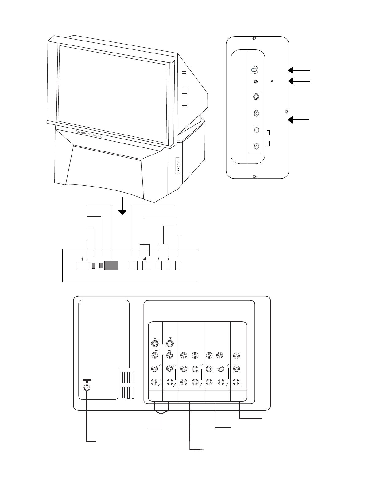
GENERAL INFORMATION C43-FD2000
ON
STAND
REMOTE CONTROL SENSOR
STANDBY INDICATOR
ON INDICATOR
POWER ON/OFF SWITCH
MAGIC FOCUS
AUTO DIGITAL
CONVERGENCE
HEADPHONE JACK
S-VIDEO
VIDEO
SIDE INPUT JACKS
( For INPUT 3)
BY
TV/VIDEO
– +
PROG
ME
NU
MAGIC FOCUS
S-VIDEO
VIDEO
L /(MONO)
AUDIO
R
L /(MONO)
AUDIO
R
SIDE CONTROL PANEL (INPUT 3)
INPUT SELECTION
VOLUME LEVEL BUTTON
CHANNEL SELECTOR
MENU BUTTON
ON
STANDBY
– +
TV/VIDEO
FRONT CONTROL PANEL
AUDIO/VIDEO
INPUTS 1,2
AERIAL TERMINAL
REAR PANEL CONNECTIONS
S-VIDEO
(MONO)
AUDIO
INPUT 1
PROG
VIDEO
L
R
S-VIDEO
(MONO)
AUDIO
INPUT 2
MENU
Y
PB/CB
L
PR/CR
R
COMPOSITE OR
(
Y P
(MONO)
AUDIO
INPUT 4
B
/
C
VIDEO
B
P
R
/
L
R
)
C
R
Y
PB/CB
PR/CR
INPUT 5
COMPOSITE OR
(
Y P
B
VIDEO
(MONO)
AUDIO
/
C
VIDEO
L
R
AUDIO
MONITOR
OUT
)
B
P
R
/
C
R
AUDIO/VIDEO INPUT 5 AND
COMPONENT INPUT
AUDIO/VIDEO INPUT 4 AND
COMPONENT INPUT
L
R
MONITOR OUTPUT
Page 15
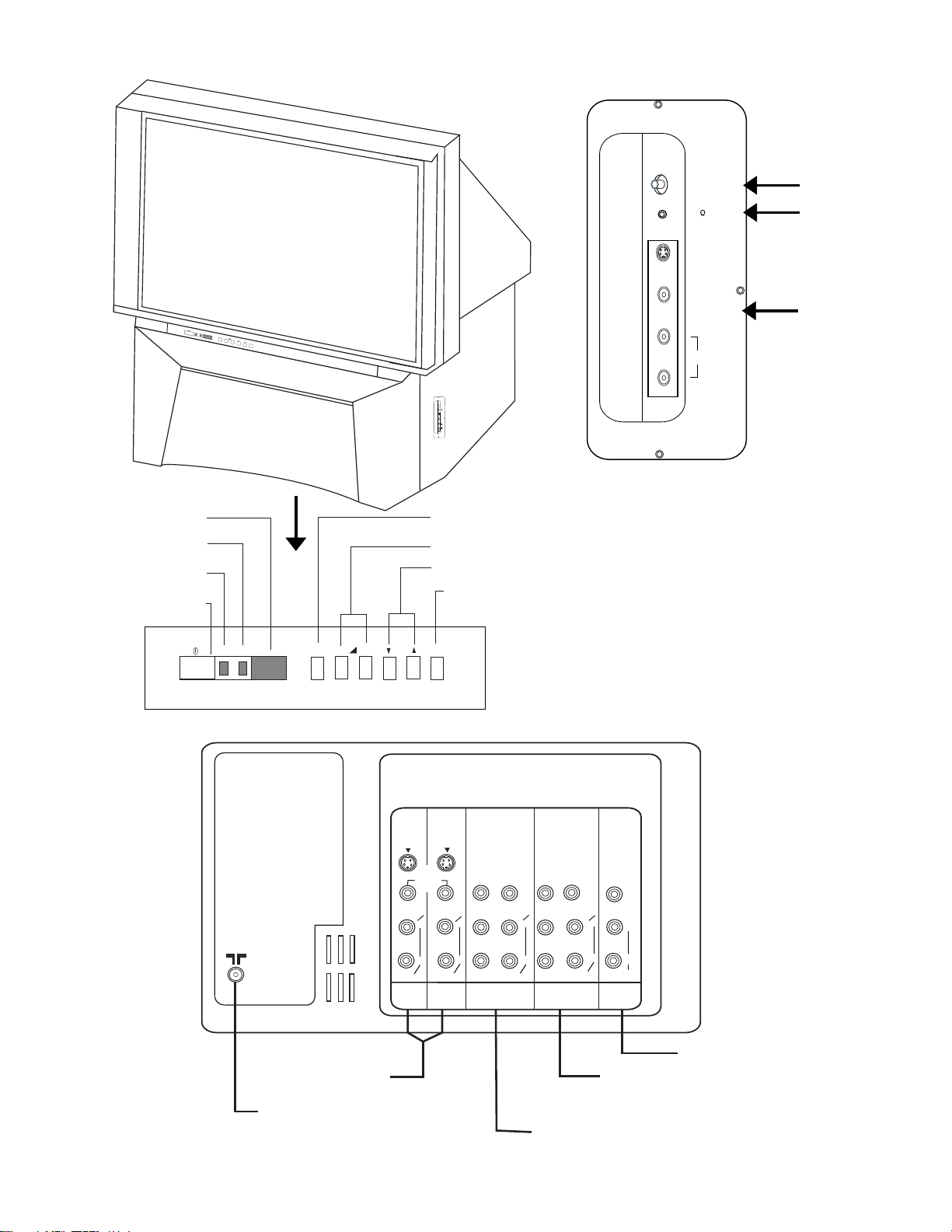
GENERAL INFORMATION C50-FD2000
REMOTE CONTROL SENSOR
STANDBY INDICATOR
ON INDICATOR
POWER ON/OFF SWITCH
MAGIC FOCUS
AUTO DIGITAL
CONVERGENCE
HEADPHONE JACK
S-VIDEO
VIDEO
ON
STANDBY
TV/VIDEO
– +
PROG
ME
NU
MAGIC FOCUS
S-VIDEO
VIDEO
L /(MONO)
AUDIO
R
L /(MONO)
AUDIO
R
SIDE INPUT JACKS
( For INPUT 3)
SIDE CONTROL PANEL (INPUT 3)
INPUT SELECTION
VOLUME LEVEL BUTTON
CHANNEL SELECTOR
MENU BUTTON
ON
STANDBY
– +
TV/VIDEO
FRONT CONTROL PANEL
AUDIO/VIDEO
INPUTS 1,2
AERIAL TERMINAL
REAR PANEL CONNECTIONS
PROG
S-VIDEO
(MONO)
AUDIO
INPUT 1
VIDEO
L
R
MENU
S-VIDEO
(MONO)
AUDIO
INPUT 2
PB/CB
L
PR/CR
R
COMPOSITE OR
(
Y P
Y
INPUT 4
B
/
VIDEO
(MONO)
AUDIO
C
B
P
R
/
C
R
Y
PB/CB
L
PR/CR
R
COMPOSITE OR
)
(
Y P
INPUT 5
B
VIDEO
(MONO)
AUDIO
/
C
VIDEO
L
R
AUDIO
MONITOR
OUT
)
B
P
R
/
C
R
AUDIO/VIDEO INPUT 5 AND
COMPONENT INPUT
AUDIO/VIDEO INPUT 4 AND
COMPONENT INPUT
L
R
MONITOR OUTPUT
Page 16

P IN P FUNCTIONS
The P IN P feature is convenient when you want to watch more than one program at the
same time. You can watch a TV program while viewing other programs from the antenna or
any of the video inputs.
1. Press the MULTI PIC. button and a sub-picture
will appear in one of the four different modes
(SPLIT , 1, 4 or 12), depending on the last selection
of the P in P mode.
To change the P in P mode, press the M. MODE
to cycle through the four different modes.
If you wish to change the volume or channel
between the main and sub-picture, press the A/B
button. A symbol will appear to indicate your
selection. Press the CHANNEL UP/DOWN or
VOLUME UP/DOWN button to change channel
or volume for the selected picture.
SPLIT mode : The main picture and the sub-pic-
ture split evenly on the screen
Mode 1 : Sub-picture will appear in one
of the three different modes,
depending on the last selection
of the P in P mode.
Mode 4 : The main and 3 sub picture
appear on the right of the
screen.
Mode 12 : In this mode all the active chan-
nels numbers (those set in
memory) will scanned and displayed as sub-picture on the
screen.
1
SPLIT mode
MODE 1
MODE 4
2 1
5
9
6
10
2
1
2
2
1
3
2
3
4
7
8
11
12
MODE 12
Note: For P in P mode 1 and mode 4 , it is not possible to select the component
input as the sub-picture if the component input is progressive.
CAUTION:
When using Picture in Picture function, the sub-picture should not be left
permanently in one corner of the screen or a “P ATTERN BURN” may develop
over a long period of time.
Page 17

P IN P FUNCTIONS
NOTE: Some P in P buttons only function in a certain mode.
Please refer to the column below.
Remote Control
Buttons
MULTI. PIC Switch ON/OFF the P in P sub-window features.
P+ / P- Increase/decrease P in P main and sub-picture channel. This
button applies only to SPLIT , mode 1 and mode 4 selection.
In mode 4, press the P+/P– button to change channel for main
picture.
If sub-picture is selected, press the P+/P– button to select between
the sub-pictures. Press the button to change the channel.
SWAP The main and sub-picture will be exchanged. This button
applies only to SPLIT and mode 1 selection.
M. MODE To change the four different P in P modes (SPLIT, 1, 4, 12).
Pressing this button will cycle through these modes.
A/B Press this button to select between main or sub-picture to
change channel or volume. A symbol will appear to indicate
your selection.This button will only operate in SPLIT , mode 1
and mode 4 selection.
FREEZE Pressing this button will split screen to main and sub-picture.
The sub-picture will be in freeze mode.
POSITION Press this button repeatedly to select position of sub-
picture. This button apply only to P in P mode 1 selection.
Details
3 ➛ 4
➛
2 1
➛
➛
Page 18
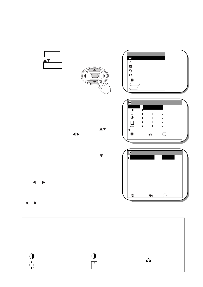
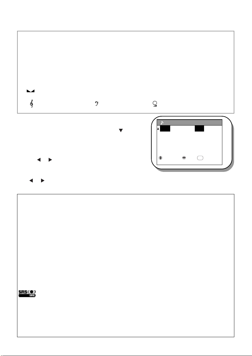
PICTURE & AUDIO SETTINGS
PICTURE SETTINGS :The PICTURE menu allows the user to select various controls,
such as mode , brightness, color, contrast and tint. To adjust these various controls, follow
the guide below.
1.
Press the MENU button.
Use the button to select PICTURE, then
press the ENTER button.
ENTER
2. The PICTURE menu is shown (right).
This menu allows the user to select and set various
standard picture controls such as MODE ( where
you can customize this mode to DYNAMIC,
NATURAL, THEATER or FAVORITE),
CONTRAST, BRIGHTNESS, COLOR,
SHARPNESS and TINT. Press the button
to select and press the button to adjust the
various setting to your desired level.
3.
In addition to these picture menu, the TV also
incorporates other controls. Press the button,
the OSD will go to page 2 of the PICTURE menu
containing controls such as COLOR TEMP,
COMB, FILM THEATER, SUPER CONT.,
NR, VM, CTI and BLACK STRETCH.
the or button to adjust the controls to your desired
level.
These features enhance and improve the
visual condition of the picture.
NOTE: If you select REFERENCE and press
or button, the setting will return to factory default
setting.
Press
the
MENU
PICTURE
AUDIO
TIMER
FUNCTION
SET UP
SELECT
ENTER
SET
MENU
EXIT
PICTURE [ 1 / 2 ]
MODE: : FAVORITE
+ 63
:
:
0
:
0
:
0
:
0
REFERENCE
SELECT SET RETURN
PICTURE
COLOR TEMP . : COOL
COMB : ON
FILM THEATER : OFF
SUPER CONT. : ON
NR : OFF
VM : ON
CTI : LOW
BLACK STRETCH : ON
REFERENCE
SELECT SET RETURN
RETURN
[2 / 2]
RETURN
DYNAMIC :
This ensures a sharp clear picture from corner to corner.
NATURAL : This mode is suitable for enjoying ordinary TV programs.
THEATER : This mode will add more realism experience.
FAVORITE : This is for your personal setting preference.
Contrast Color
Brightness Sharpness
Tint
Page 19
PICTURE & AUDIO SETTINGS
NOTE :
TINT
is only selectable when
NTSC
is detected.
SUPER CONT ., NR, VM and CTI
are selectable when the Picture mode is in FAVORITE.
FILM THEA TER is selectable when the Picture mode is in THEATER or FAVORITE.
COLOR TEMP. :Set this to WARM for hotter colors with more red or COOL for
less intense colors with more blue or NORMAL for standard color .
COMB : This function is used when using PAL system or when picture has
cross color.
FILM THEATER : Use this function when watching movies from film (cinema sources).
This is to smooth jagged edges.
SUPER CONT . : Turn on SUPER CONTRAST to improve picture detail in areas
of high brightness.
NR :
The NR function automatically reduces conspicuous noise in the
picture without degrading picture quality.
VM
:The VM function improves the sharpness of the picture to produce
clearest resolution and superb picture quality.
CTI :The CTI function improves color resolution at the edges to produce
clear and distinct colors.
BLACK :This function is to enhance the darker portions of the picture for
STRETCH
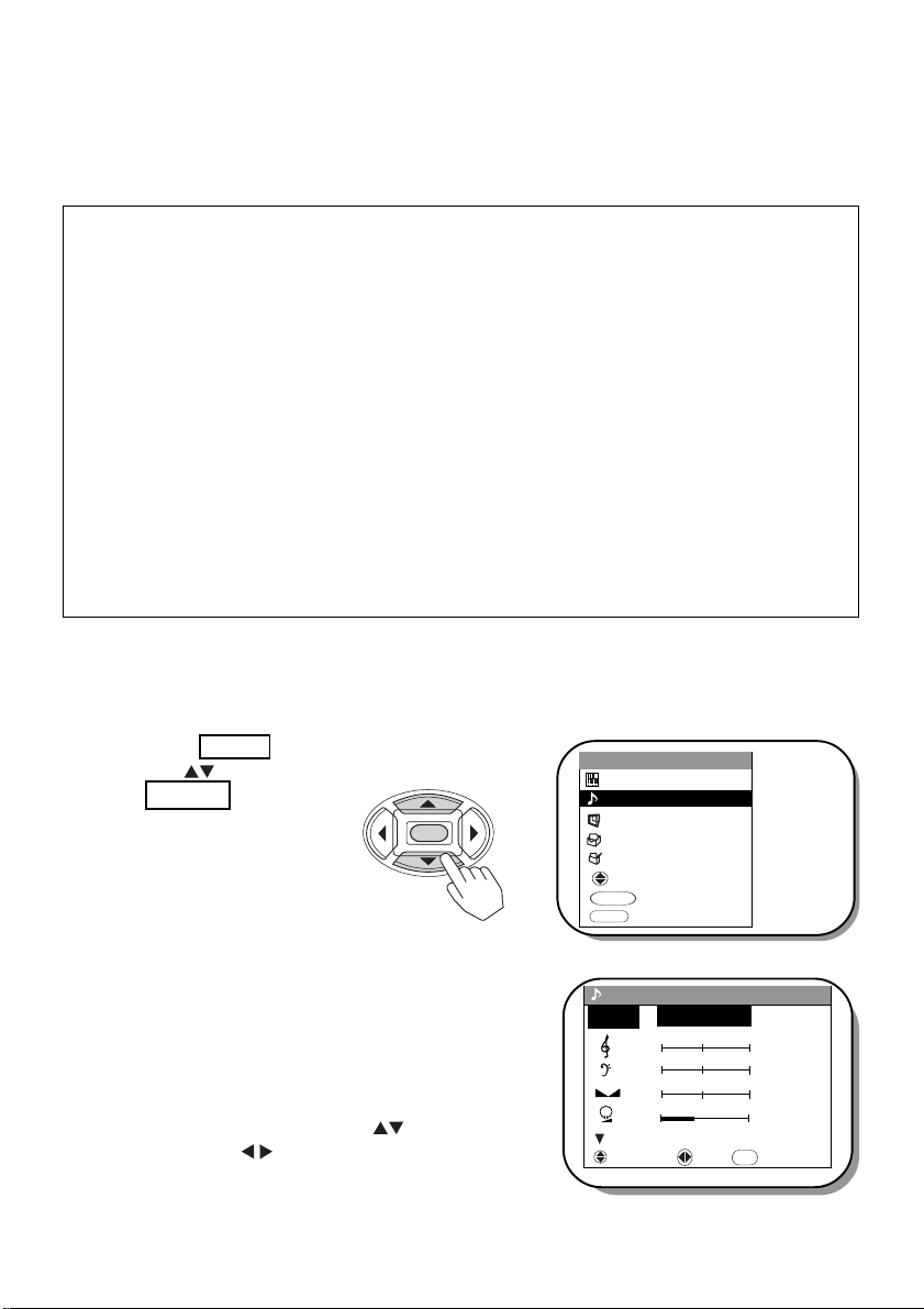
AUDIO SETTINGS
such as mode,treble, bass, balance and headphone volume. To adjust these various controls,
follow the guide below.
1. Press the MENU button.
Use the button to select AUDIO, then press
the ENTER button.
added realism and overall picture quality.
: The AUDIO menu allows the user to select various audio controls
MENU
PICTURE
AUDIO
ENTER
TIMER
FUNCTION
SET UP
SELECT
ENTER
SET
MENU
EXIT
2. The AUDIO menu is shown (right).
This menu allows the user to select and set various
standard audio controls such as MODE (where you
can customize this mode to FAVORITE,
THEATER, MUSIC or NARRATION),
TREBLE, BASS, BALANCE and HEADPHONE VOLUME. Press the buttons to select
and press the buttons to adjust the various
setting to your desired level.
AUDIO [ 1 / 2 ]
:
MODE
:
: +20
REFERENCE
SELECT SET RETURN
: 0
:
0
0
FAVORITE
RETURN
Page 20
PICTURE & AUDIO SETTINGS
FAVORITE : Use this mode for your personal setting preference.
THEATER : Use this mode to improve audio performance when watching
MUSIC :
NARRATION : Use this mode for outstanding vocal clarity.
Speaker (Left/Right) Balance
Treble Bass Headphone Volume
movies based sources.
Use this mode for enhanced high frequency.
3.
In addition to these audio menu, the TV also
incorporates other controls. Press the button,
the OSD will go to page 2 of the AUDIO menu
containing controls such as SRS, BBE,
PERFECT VOLUME and LOUDNESS. Press
the or button to adjust the controls to your
AUDIO [2 / 2]
SRS : OFF
BBE : ON
PERFECT VOL. : OFF
LOUDNESS : ON
REFERENCE
SELECT SET RETURN
RETURN
desired level.
NOTE: If you select REFERENCE and press the
or button, the setting will return to factory
default setting.
SRS
The SRS surround sound expands the audio listening field wider and deeper to create ex ceptional sound quality from the TV’s speakers.
BBE
The BBE system enhance the clarity of high-frequency sound.
PERFECT VOL.
When the volume is markedly different among stations, it can be automatically adjusted
by setting this function to [ON].
LOUDNESS
The function which corrects a small sound in the clear quality of sound.
is a trademarks of SRS Labs, Inc.
SRS technology is incorporated under license from SRS Labs, Inc.
Manufactured under license from BBE Sound, Inc. Licensed by BBE Sound
Inc. under USP4638258 and 4482866. BBE and BBE symbol are registered
trademarks of BBE Sound, Inc.
Page 21
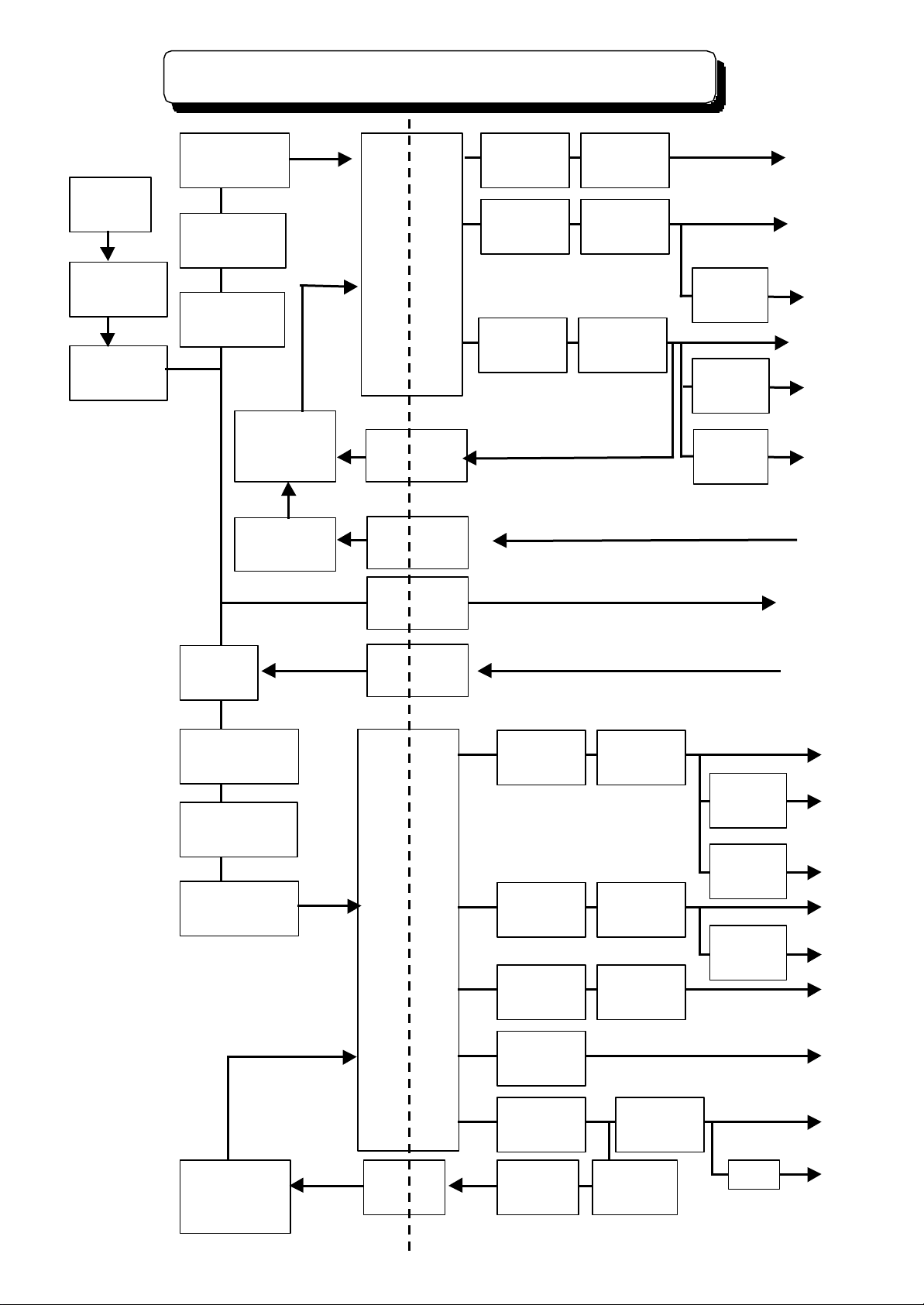
PROTECTION CIRCUIT BLOCK DIAGRAM
Hot
Cold
PROTECTION CIRCUIT BLOCK DIAGRAM
AC Cord
E901
Fuse
T4AL : F908
Noise Filter
L901, L902
Fuse
T3.15AL:F902
Rectifier
D901
Noise Filter
L911
Switching
Control
I901
Protect
Q902, Q903
Switching
Transformer
T901
Feedback
I902
Protect
I903
ACK
I904
Protector
E903 : 5000
Protector
E904 : 5000
Protector
E905 : 5000
Rectifier
29V : D931
Rectifier
11V: D932
Rectifier
7V : D935
Regulator
I907
Regulator
I905
Regulator
I906
AUD+30V
SW+11V
FC 3.3V
SBY+7V
SBY+5V
FB+5V
VM
Protector
Relay
S901
Noise Filter
L905
Rectifier
DP01
Fuse
T3 15AL: FP01
Relay Drive
Q932
Switching
Transformer
TP01
Protector
EP33:5000
Protector
EP31:10K
Protector
EP32:10K
Rectifier
220V:DP32
Rectifier
+8V:DP35
Rectifier
+28V:DP33
Rectifier
-28V:DP34
Regulator
-7V:IP05
Regulator
6.3V:IP06
Regulator
12V:IP04
TV ON/OFF
SW+8V
SW-8V
Heater
+28V
SW+12V
-28V
220V
Switching
Control
IP01
Feedback
IP02
Rsctifier
120V:DP31
Error Amp
IP03
Protector
EP35 :3000
EP36 : 500
+B
RP44Protector
SW+33V
Page 22

Page 23

Page 24

Page 25

Page 26

Page 27

Page 28

Page 29

Page 30

Page 31

Page 32

Page 33

Page 34

Page 35

Page 36

Page 37

Page 38

Page 39

Page 40

Page 41

Page 42

Page 43

Page 44

Page 45

System Control Circuit
Tuner Circuit
Description
Cir#
Pin
Voltage (V)
Description
Cir#
Pin
Voltage (V)
Cir#
Pin
Voltage(V)
Description
Cir#
Pin
Voltage (V)
Description
Cir#
Pin
Voltage (V)
Cir#
Pin
Voltage(V)
H8S/2238W
I00110.14
H8S/2238W
I001860.00
Q001C5.20
NJW1137M
I40114.50
MSP3455G
I101200.00
Q101C0.0020.14870.00B4.7024.50210.00B0.7435.00884.70E4.0034.50225.00E1.4340.00894.70
Q002C0.0044.50230.00
Q102C0.0055.00900.00B5.3054.50240.00B0.7865.00915.00E5.2064.50250.00E1.4675.00925.00
Q006C5.2074.50260.00
Q103C5.0085.00935.00B0.0084.50270.00B1.0095.00945.00E0.0090.95280.00E0.38105.00955.00
Q007C5.20104.50290.00
Q104C9.00115.00960.00B0.00113.40303.80B5.00125.00970.00E0.00123.40313.80E4.50135.00980.00
Q009C8.02134.70320.00
Q105C9.00140.00990.00B0.09144.80338.40B4.10150.00
100
0.00E0.00150.00347.40E3.50160.00
CAT24WC32J1
I00210.00
Q010C0.00169.00350.00
Q106C9.00170.0020.00B8.30170.00363.70B4.10180.0030.00E0.01185.00373.70E3.50190.0040.00
Q011C10.49193.40383.70
Q108C0.00200.0055.00B0.00203.20390.00B2.00210.0065.00E0.00214.50403.70E2.60220.0070.00
Q012C5.20224.50413.70
Q109C0.03230.0085.00B0.00234.50422.60B0.62242.50
MB90096
I00311.20E0.00244.50433.70E0.00252.5020.00
Q013C4.40254.50440.00
Q110C0.00265.0031.20B0.00264.50B0.00275.0040.00E0.00274.50E0.00280.0055.00
Q014C5.00284.50
Q401C0.00290.0065.00B0.00294.50B0.00305.0070.00E0.00304.50E0.00315.0084.40
NJM2198M
I40210.00
Q402C0.00325.0090.0024.50B0.00335.00105.0034.50E0.00345.00110.0044.50
Q403C12.92355.00124.4054.50B0.00365.00135.0064.50E0.00375.00144.4074.50
Q404C0.00385.00150.0084.50B0.00395.00160.0094.50E0.00401.90170.00109.00
Q405C0.25415.00180.00110.00B36.00421.90190.00124.60E36.00430.00200.00130.00
Q406C39.30442.40213.00140.00B0.04450.00225.00154.50E0.00460.00230.00164.50
Q407C0.04470.00245.00174.50B0.62482.40255.00184.50E0.00492.70265.00190.00502.30275.00204.50513.80283.00214.50525.00
HD74HC08FP
I00410.00224.50535.0020.00234.50545.0030.00244.50555.0040.00
TA8258H
I40312.40565.0055.0022.60570.0060.0030.00580.0070.0042.60595.0080.0052.40605.0095.00612.30615.00100.00719.00625.00110.0085.00632.50125.00939.50640.00130.00100.00652.50145.00114.30660.00
HD74HC08FP
I00510.001219.00675.0020.00
MSP3455G
I10115.00680.0030.0021.50690.0040.0031.50700.0055.0040.00710.0060.0052.30720.0070.0062.00735.0080.0070.00740.0095.0080.00750.00100.0090.00760.00110.00100.00775.00125.00115.00785.00130.00125.00795.00145.00135.00805.00
PST994D-T
I00615.00140.00815.0020.00150.00825.0035.00160.00835.00170.00845.00180.00855.00195.00
Page 46

Video Chroma Circuit
Teletext Circuit
Headphone Amplifier Circuit
Focus Circuit
Sensor Distribution Circuit
Description
Cir#
Pin
Voltage (V)
Description
Cir#
Pin
Voltage (V)
Cir#
Pin
Voltage(V)
Description
Cir#
Pin
Voltage (V)
Description
Cir#
Pin
Voltage (V)
Cir#
Pin
Voltage(V)
Cir#
Pin
Voltage(V)
TB1274AF
I50112.23
BA055FP-E2
I50313.20
Q503C0.00
AT24C04
IT0310.00
BA35BOFS
IA0110.00
QF02C10.70
QL10C0.4021.9327.00B1.5920.0022.70B11.20B4.7031.2030.00E2.2330.0035.07E643.00E0.0044.6045.00
Q504C0.0040.0042.70
QF03C3.00
QL11C0.4052.2050.00B1.7653.3050.00B3.50B4.7064.96E2.4063.3060.00E8.90E0.0072.45
Q505C0.0070.0072.70
QL12C0.4080.00B1.7183.3080.00B4.7090.31E2.40
SAA5264
IT0514.6799.00E0.00104.00
Q506C0.0024.70102.72
QL13C0.40112.23B4.5434.73110.00B4.70125.00E5.1944.70125.55E0.00134.20
Q507C6.4054.60132.70
QL14C0.40143.73B0.0064.54145.08B4.70150.00E0.0074.54152.70E0.00160.00
Q511C0.0084.50162.72
QL15C0.40170.00B1.5894.46B4.70180.00E2.23104.50E0.00191.58
Q512C0.00114.55
QL16C0.40201.76B1.77124.48B4.70211.70E2.40130.00E0.00221.70
Q513C0.00143.30
QL17C0.40231.70B1.78153.30B4.70240.00E2.42164.48E0.00252.43
Q514C0.00174.50262.43B2.13184.48272.43E2.79194.46280.00
Q516C6.35204.58292.21B0.00214.70302.16E0.00220.00311.35
Q517C0.00231.10324.85B1.65240.00332.04E2.31250.67342.30
Q518C0.00261.62352.32B2.30270.00360.00E2.14280.00374.85
Q519C4.70294.46383.83B0.00304.44391.64E0.00313.25402.73
Q520C5.06320.00411.87B3.60330.00424.85E2.94340.00431.67
Q521C5.06352.80442.11B3.59362.00454.61E2.93372.50465.01
Q522C0.00380.00473.72B2.31393.25481.63E2.13400.00
TB1274AF
I50212.86
Q523C4.67411.7021.93B0.06421.6031.20E0.00430.0044.95
Q524C8.93443.2552.87B3.50454.6264.97E4.03464.6072.40
Q525C8.93474.6080.00B6.39484.5390.31E5.72494.83104.00
Q526C5.01504.70112.23B3.61514.20125.00E2.90524.20135.00
Q527C0.00144.80B2.15
Cir#
Pin
Voltage(V)
15
0.00E1.48
QT02C0.00160.00
Q528C5.01B1.47170.00B3.61E2.11180.00E2.97
QT09C0.00191.40
Q529C0.00B0.00202.40B1.49E5.00211.58E2.15
QT10C0.00221.75
Q530C5.00B0.00231.77B2.48E5.00240.00E1.80
QT11C0.00252.43
Q531C0.00B0.00262.43B0.93E5.00272.43E1.58280.00
Q532C5.01292.20B3.71302.18E3.08311.38
Q533C0.00324.85B1.54332.20E2.19342.30
Q534C5.01352.31B3.50360.00E2.86374.85
Q535C0.00383.83B1.44391.66E2.09403.34
Q536C8.94412.24B4.05422.60E4.13431.50
Q537C8.94442.12B6.34454.95E5.66462.21473.73481.46
Page 47

AV Switch / Terminal Circuit
YC - Separator/ Comb Filter Circuit
Description
Cir#
Pin
Voltage (V)
Cir#
Pin
Voltage(V)
Description
Cir#
Pin
Voltage (V)
Description
Cir#
Pin
Voltage (V)
Cir#
Pin
Voltage(V)
Cir#
Pin
Voltage(V)
CXA2069Q
I20113.85
QA01C8.36
TC90A69N
I30111.30
UPD64083GF-3BA
I3A1400.00
Q301C8.90
Q339C3.0024.38B4.4023.16
3DYC410.00B5.00B2.2733.85E3.7435.00420.00E4.30E1.7844.38
QA02C4.8942.50430.00
Q302C8.90
Q340C0.0054.37B8.3650.00440.00B2.20B2.9860.00E8.9561.84452.44E1.60E3.2874.83
QA03C8.3772.23462.40
Q305C0.00
Q341C3.0083.85B4.4080.00471.06B3.10B0.0094.38E3.7590.00481.13E3.80E0.00103.85
QA04C4.51100.00490.00
Q307C9.00
Q3A1C0.00114.38B8.37115.00501.45B2.70B1.53124.37E8.95120.00510.00E2.13E2.20130.00
QA05C5.34135.00520.00
Q308C0.00
Q3A6C0.00144.84B0.00140.00532.40B3.70B1.37153.85E0.00154.22540.00E4.30E9.00164.38
QA06C0.00163.73550.00
Q310C9.00
Q3A8C9.00173.85B5.19170.00560.00B7.70B5.12184.38E5.55180.00573.27E2.10E4.46194.37
Q201C8.90192.53580.00
Q311C9.00
Q3A9C0.00200.00B4.20205.00594.27B1.10B1.45215.18E3.50210.00603.73E5.00E9.00223.85
Q202C8.90223.00610.00
Q312C9.00
Q3E2C8.98234.38B4.30233.00623.28B2.00B5.20244.00E3.70243.40632.42E1.60E4.54254.37
Q203C8.90253.16642.40
Q313C0.00264.37B4.30260.00650.00B3.16270.00E3.60273.70660.00E3.80284.84
Q204C8.90281.56672.45
Q315C9.00294.38B3.14
TC90A69N
I30311.30680.00B2.70303.85E2.5023.16690.00E2.00314.38
Q205C8.9035.00700.00
Q316C0.00320.00B4.3042.50710.00B3.50334.24E3.6050.00720.00E4.30343.70
Q206C0.0061.84730.00
Q318C9.00350.00B1.4072.23740.00B2.75364.36E2.1080.00750.00E2.13374.37
Q207C7.4090.00762.98
Q319C2.71384.40B2.18100.00770.00B8.30393.60E1.40115.00780.00E9.00404.40
Q208C0.00120.00790.00
Q320C8.30414.27B1.45135.00800.00B2.70428.84E2.10140.00812.40E2.70434.40
Q210C8.90154.81821.00
Q321C2.70444.16B4.40164.76831.45B8.35454.40E3.70170.00841.36E9.00463.60
Q211C8.90180.00850.00
Q322C8.35474.36B5.30192.53860.00B2.78480.04E4.70205.00870.00E2.21494.02
Q214C8.90210.00881.00
Q323C0.00504.40B5.30223.00890.70B1.61514.36E4.60233.00900.70E2.26524.40
Q215C8.90243.42911.20
Q324C0.00534.27B5.30253.16922.40B1.61544.40E4.60260.00932.40E2.26553.60
Q217C8.90273.70940.00
Q325C2.77563.14B4.40281.63950.00B8.35570.00E3.70
UPD64083GF-3BA
I3A110.00961.06E9.00584.27
Q218C8.90
3DYC20.00970.00
Q326C8.35594.37B5.3030.00980.00B2.78604.47E4.6040.00990.00E2.21614.38
Q221C8.9050.00
100
2.44
Q327C2.74624.37B5.2060.00
PST9227NR
13A210.50B8.35634.17E4.6070.0020.00E9.00644.37
Q222C8.9080.0030.00
Q328C8.35652.50B5.3090.0045.27B2.78
MM1113
I20514.93E4.60100.0053.28E2.2120.00
Q230C7.40110.00
TK11125CS
13A413.27
Q329C6.1234.95B2.10120.0020.00B8.3340.00E1.44130.0031.28E9.0054.95
Q231C0.05140.0042.50
Q330C8.3468.83B0.60150.0053.28B2.7874.22E0.00160.00E2.2180.00
Q232C4.40170.00
Q331C5.20B5.00180.00B8.33E0.00190.00E8.98
Q233C8.90200.00
Q332C8.33B4.28210.00B2.81E3.60220.00E2.24
Q237C0.00230.00
Q334C0.00B1.50240.00B2.28E2.10250.00E2.87
Q238C8.80260.00
Q335C0.00B4.20270.00B2.30E3.50280.00E2.90290.00
Q336C8.90300.00B2.15312.40E2.30322.40
Q337C0.00330.00B2.36340.00E3.02350.00
Q338C0.00360.00B2.36370.00E3.03383.30390.00
I201 Pin 52 Vpp : 720.0mv 1v/div
I201 Pin 54 Vpp : 720.0mv 1v/div
I201 Pin 38 Vpp : 720.0mv 1v/div
I201 Pin 40 Vpp : 720.0mv 1v/div
I201 Pin 53 Vpp : 2.440v 1v/div
I201 Pin 56 Vpp : 2.440v 1v/div
I201 Pin 41 Vpp : 2.440v 1v/div
I301 Pin 7 Vpp : 640.0mv 1v/div
I301 Pin 25 Vpp : 1.800v 1v/div
I301 Pin 27 Vpp : 640.0mv 1v/div
I303 Pin 7 Vpp : 1.000v 1v/div
I303 Pin 25 Vpp : 2.040v 1v/div
I303 Pin 27 Vpp : 640.0mv 1v/div
Page 48

Convergence Circuit
Deflection Circuit
Description
Cir#
Pin
Voltage (V)
Cir#
Pin
Voltage(V)
Description
Cir#
Pin
Voltage (V)
Cir#
Pin
Voltage(V)
Description
Cir#
Pin
Voltage (V)
BA17805
IK0117.50
QK01C0.00
LA7845N
I60110.00
Q604C0.30
6P-MINI
PMB114.6020.00B1.5920.00B27.00214.60
3
5.00E2.23314.50E27.504120.00
PST994D
IK0214.50
QK02C0.00426.60
Q706C11.806120.00
2
0.00B1.7653.00B0.90
6P-MINI
PMG114.60
3
5.00E2.4063.00E1.50214.60
STK392-120
IK0410.00
QK03C0.00727.00
Q707C0.034120.00
2
0.00B1.7181.40B0.706120.00
3
-31.00E2.409-E0.00
6P-MINI
PMR114.604-32.10
QK06C0.0010-
Q708C15.00214.60
5
32.50B4.54
TA1317AN
I70114.90B0.034120.00
6
0.50E5.1920.40E0.006120.00
7
0.32
QK07C6.4030.00
Q709C15.00
7P-JP
PSD110.008-27.50B0.0043.00B0.3620.00
9
0.38E0.0054.90E0.0030.00
10
27.30
QK08C0.0064.50
Q710C1.2040.00110.00B1.5879.50B0.0050.00
12
-27.30E2.2380.86E0.0065.0013-0.1090.00
Q711C0.0070.00
14
-0.05104.70B27.00
13P-JP
PSD211.20
15
-0.10111.30E0.0021.50
16
-0.10121.00
Q712C5.0030.0017-27.50134.80B0.00412.50
18
-0.10144.80E0.0050.00
STK392-120
IK0510.00150.00
Q754C0.4060.0020.00163.60B6.5070.00
3
-30.90174.00E6.0080.60
4
-30.10183.40
Q777C120.00
9
0.005-32.50194.50B0.06105.20
6
0.10201.20E0.00110.70
7
0.10215.20
QH01C250.00
12
5.10
8
-27.50224.20B1.50130.0090.20234.00E0.22
13P-JP
PSD310.001027.30242.60
QH02C1.5024.80
11
-0.20
M62501P
IH0116.50B0.6030.00
12
-27.50211.60E0.0044.80
13
-0.2030.80
QN01C0.6050.0014-0.2042.40B0.0069.50
15
0.0051.60E0.0070.00
16
0.006-
QN02C5.8080.3017-27.5070.00B11.3090.00
18
0.0080.00E11.501014.60
9
7.10
QN03C11.40110.00107.10B0.20120.00
11
7.10E0.001331.00
12
7.10
QN04C11.40
7P-JP
PDK110.00132.80B0.9020.00
14
2.00E0.6030.00
15
5.00
QN05C11.7040.00
16
0.00B0.0050.00E0.0065.00
QN06C0.0070.00
B
0.00
JP-11P
PDK310.00
E
0.0020.00
3
7.604-7.3050.7060.0071.5080.309-0.50105.10
11
0.00
7P-JP
PDK4112.0020.0033.404-53.6060.00
7
-
PDS Pin 13 (BV)
PDS Pin 14 (BH)
PDS Pin 16(GV)
PDS Pin 17 (GH)
PDS Pin 19 (RV)
PDS Pin 20 (RH)
Q709 Colector Pin Vpp : 42v 200v/div
QH01 Colector Pin Vpp : 400v 200v/div
QH01 Base Pin Vpp : 10.08v 200v/div
PSD2 Pin 1 Vpp : 3.360v 200v/div 10us/div
I701 Pin 4 Vpp : 1.200v 200v/div 5ms/div
I601 Pin 3 Vpp : 56v 200v/div 5ms/div
IH01 Pin 1 Vpp : 14.4v 200v/div
I601 Pin 4 Vpp : 34.80v 200v/div 5ms/div
I601 Pin 8 Vpp : 35.2v 200v/div
Q777 Colector Pin Vpp : 1.024kv 200v/div
Page 49

Signal Power Supply Circuit
Power Supply Circuit
Cir#
Pin
Voltage(V)
Description
Cir#
Pin
Voltage (V)
Description
Cir#
Pin
Voltage (V)
Cir#
Pin
Voltage(V)
Q903C19.50
STR-X6468
I9011324.00
STR-F66688
IP0111.50
QP01C45.60B0.0020.0020.00B320.00
E
0.00319.603321.00
E
320.00
Q903C0.0040.00415.00
QP02C1.20
B
19.5050.0050.00B-E19.5060.00
TLP421
IP02190.70E15.50
Q905C0.0071.30290.00
QP31C0.00
B
23.00
TLP421 FB
I90216.3031.30B120.00
E
19.5025.20414.80E120.70
Q932C0.0030.00
SE120N
IP031120.00
B
0.8042.70290.00E0.00
TLP421 PRO
I90316.0030.00
Q933C3.8026.00
NJM7812FA
IP04127.30B0.0030.0020.00
E
0.00419.50312.00
Q934C0.00
TLP421 ACK
I904166.00
PQ1CF2
IP05115.00B3.80270.0027.30
E
3.8033.4030.00
Q936C6.0045.0041.30B0.00
SI3050N
I90510.0058.20E0.002-
PQ5RD083
IP0617.60
Q939C5.4035.7026.30B4.6045.1030.00
E
5.4056.304-
Q940C0.00
SI3050N
I90610.00
XA-5P
PDC11220.00
B
3.0023.802-
E
3.0035.403272.00
Q941C0.0045.0040.00
B
0.7556.3056.30E0.00
SI8033S
I907111.20
2
3.7030.0043.40
5
2.40
XA-14P
PQS110.0020.0033.8040.0055.4060.0075.4085.4090.00100.00110.00123.50133.50
14
3.50
XA-9P
PQS216.0026.0030.00411.00511.0060.0070.0086.00
9
0.00
XA-4P
PQS3138.10238.1030.00
4
0.00
XA-6P
PQD210.0020.0030.0040.0050.55
6
0.00
PSD2 Pin 2 Vpp : 13.20v 200v/div 10us/div
PSD2 Pin 11 Vpp : 14.4v 200v/div
I901 Pin 1 Vpp : 536v 100v/div
I901 Pin 3 Vpp : 576v 100v/div
PWB Pin 1 Vpp : 36.4v 200v/div 5ms/div
PMG Pin 7 Vpp : 19.2v 200v/div 5ms/div
PMG Pin 4 Vpp : 296.0v 100v/div 5us/div
PMG Pin 6 Vpp : 1.048kv 200v/div 5us/div
PMR Pin 1 Vpp : 4.400v 200v/div 5ms/div
Page 50

Deflection Control Circuit
Power Regulator Circuit
Signal Processing Circuit
Description
Cir#
Pin
Voltage (V)
Cir#
Pin
Voltage(V)
Cir#
Pin
Voltage(V)
Description
Cir#
Pin
Voltage (V)
Description
Cir#
Pin
Voltage (V)
Description
Cir#
Pin
Voltage (V)
TA1316
IC0111.40
QC01C9.30
QCA1C9.10
SI-3018LSA
IG0113.30
TA1370FG
IL0110.00
74HC221
IL0593.9025.70B5.60B3.9022.6020.00105.0035.00E5.00E3.6033.3030.30115.0045.00
QC02C0.00
QCA2C3.6042.3745.00120.2055.00B1.66B1.9050.0050.00135.0060.00E2.30E1.2060.0060.00140.0070.16
QC03C0.00
QCA3C7.8071.8076.30152.7085.00B1.70B4.3081.8080.00165.0095.00E2.30E3.60
SI-3050F
IG0210.0095.00
MM1519XQ
IX0110.00105.00
QC04C5.60
QCA4C8.4024.50100.0020.00111.00B5.30B1.5035.00119.0030.00120.00E4.65E0.8845.00122.6049.00130.00
QC05C4.68
QCA5C4.0255.90130.0055.00142.90B8.00B8.45
SI-3090F
IG0310.00140.0060.00153.00E4.60E9.10210.88150.1374.80161.60
QC06C9.30
QCA6C0.0039.00160.6380.00171.10B5.30B4.0049.00170.0094.80180.00E4.70E4.70510.88180.00100.00199.20
QC08C9.30
QCA7C3.40
SI-3090F
IG0410.00190.00110.00206.10B9.20B7.40210.88200.00120.00215.60E8.60E8.0039.30215.00130.00226.00
QC09C9.20
QCA8C0.0049.00225.00149.00232.50B0.00B2.70510.88230.00155.00241.30E0.00E3.40242.00160.00250.00
QC10C9.20
QCA9C3.40
Cir#
Pin
Voltage(V)
25
5.30174.80261.30B1.10B7.40
QG01C0.00262.20180.00275.00E1.00E8.00B0.67270.00194.80280.00
QC13C9.10
QCB1C0.00E0.00285.00200.00292.10B0.15B2.70290.00210.00304.80E0.42E3.40300.00220.00314.80
QC14C0.00
QCB2C3.40
TA1370FG
IL0210.30230.00320.00B1.00B7.4020.00240.00334.00E1.60E8.0030.30250.00344.00
QC15C9.20
QCB3C0.0045.00263.70354.00B0.60B2.8050.00274.20360.52E1.30E3.4060.00285.00374.00
QC16C9.20
QCB6C0.0076.30290.00384.00B0.35B0.7080.00300.00394.00E1.30E0.0095.00310.00409.20
QC17C0.00100.00325.00412.80B0.00119.00330.00422.80E0.63122.60344.50432.80
QC18C0.00130.00350.00440.00B0.00140.00364.50459.20E0.63150.12370.00464.70
QC19C0.00160.63384.50474.70B0.00170.00399.00484.50E0.63180.00404.50490.00
QC20C0.00190.00410.00500.00B0.00200.00424.50510.00E0.64215.00430.00520.55
QC21C0.00225.00444.50536.20B0.00234.40459.00544.50E0.64242.00464.50559.20
QC22C0.00255.30470.00565.50B0.00262.20484.40
BU4053BCF
IC0310.00E0.64270.00490.0020.00
QC23C9.20285.00504.5030.00B8.40290.00519.0040.00E1.80300.00529.0050.00
QC24C9.20
SN74HC14NS
IL0315.00535.0060.00B0.0020.13540.0070.00E0.0030.63554.8480.00
QC25C9.2044.13560.0094.40B0.0050.63574.84104.40E0.0064.13589.00114.40
QC26C0.0070.00595.00123.20B0.2280.13600.00132.70E0.0095.00614.83142.40
QC27C5.90105.00620.00150.00B0.00110.18634.83165.00E0.00125.00640.00
QC30C9.20130.18B0.00145.00E0.00
74HC221
IL0513.9025.0035.0040.1755.0060.0072.7080.00
IC01 Pin 4 Vpp : 760.0mv 1v/div
IC01 Pin 3&8 Vpp : 760.0mv
IC01 Pin 15 Vpp : 3.520v 1v/div
IC01 Pin 31 Vpp : 5.320v 1v/div
IC01 Pin 16 Vpp : 3.680v 1v/div
IC01 Pin 30 Vpp : 5.160v 1v/div
Page 51

Trouble Shooting Guide For DP2M
No Item Changed Adjustment necessary
1 Signal PWB White Balance/ Sub-bright.
Tuner (AGC)
Horizontal phase / Vertical phase
2 Tuner (Main/ Sub) AGC
3 Micon (I001) No adjustment necessary
4 Feature Box No adjustment necessary
5 Sub Signal PWB Tint adjustment
6 Audio control/ amplifier No adjustment necessary
I101 (MSP3455G)
I403 (TA8258H)
I401 (NJW1137)
I402 (NJM2198)
IA01(BA3530FS)
I201(CXA2069Q)
7 EEPROM(I002) Micon Initialize
Same adjustment as Signal PWB
8 Video Chroma IC Tint adjustment
I501(TB1274AF)
9 Def/ RGB IC White Balance
IC01(TA1316) Horizontal Position (50Hz/ 60Hz)
Sub-bright
10 Power Deflection PWB Horizontal/ Vertical size (V. res)
Horizontal (I2C bus)
High Voltage adjustment
Cut off (screen) adjustment
11 Convergence PWB Convergence (NTSC-50p/ PAL-50p/ PAL-100i)
DCU unit (UKDG) Phase data
Focus adjustment
12 Terminal PWB, Sensor PWB, Power Sup PWB No adjustment necessary
13 PRT tube All related lens adjustment (focus, etc)
White Balance, convergence
14 CPT PWB White Balance adjustment
15 DY change All related lens adjustment (focus, etc)
Convergence
16 Synchronized Deflection Sys. Control IC High Voltage adjustment
IH01(M62501P) Cut off (screen) adjustment
FBT (TH01)
17 Deflection processor IC Horizontal adjustment
I701(TA1317AN) Vertical size adjustment
Trapezoid Distortion adjustment
Side pin adjustment
Page 52

1. No Raster and No Power
N
N
N
o raster and
No sound
TROUBLE SHOOTING
TROUBLE SHOOTING
F908 blown?
POWER SUP PWB
No
Any click
sound from
S901?
POWER SUP PWB
No
5V at I001 (62) ?
Yes
Check D901, DP01, X901 and others connected
to AC main
POWER SUP PWB
POW/DEF. PWB
Yes Yes No
Yes
S901 turns off
Immediately after switch
TV on?
No
Go to 'Pow./Def. PWB check
o TV -ON signal,
Check I001, QG01, Q939,
I905, I906 and Q932
POWER SUP PWB
flow'
Power indicator DM03
light?
Yes
Front Panel
Over current of VM.
Check QE06, QE07, QE56, QE57, QEA6,
QEA7, & others at VM circuit
CPT/VM PWB
No
SIGNAL PWB
7 at C936(+)?
Yes
SIGNAL PWB
POWER-SUP PWB
o STBY5V.
Check I905 and etc.
POWER-SUP PWB
No
SIG-POWER failure,
See 'Sub-Power check flow'
Page 53

DEF-POWER failure:
N
y
Main-Power check flow
FP01
blown?
No
Yes
Check the other
DIAGNOSIS LED
No
POW./DEF. PWB
DP09 is lit?
POW./DEF. PWB
POW./DEF. PWB
Yes
No
Over current in live side.
Check IP01, TP01, CP06, and others connected
to IP01(3)
POW/DEF. PWB
o Power for IP01.
Check IP01, DP07, DP15, DP08, QP01, RP17, RP18
and etc.
POW/DEF. PWB
Yes Yes
Some LED are lit? Some LED are not lit?
DP47 is not lit.
DP48 is not lit.
NO +B (120) for H def. and HV
Check DP31, CP32, IP03, EP35, EP36,
QH01 others connected to +B line.
POW./DEF. PWB
NO +28/-28V for V def. and Conv.
Check EP31, EP32, DP33, CP36, DP34,
CP38 and etc.
POW./DEF. PWB
No No
POW./DEF. PWB POW./DEF. PWB
Deflection circuit
Check flow
20V
0V
While the startup,
V>20V at IP01(4)
transientl
No
Check DP32, CP34, DP31
?
POW./DEF. PWB
Yes
+B error Amplider is not function
Check DP31, GP32, IP02, IP03 and EP36
POW./DEF. PWB
power on
POW./DEF. PWB
15V
10V
DP49 is not lit.
NO power for digital conv. Unit.
Check EP33, DP35, CP40, IP05, DP50,
CP48 and etc.
POW./DEF. PWB
CONV. PWB
Page 54

SIG-POWER failure:
y
N
N
Sub-Power check flow
While the startup,
V>0.5V at I903(1)
transiently
No
POWER-SUP
PWB
Yes
Over voltage of STBY5V
Shutdowned by PROTECTION:
Check I905 and short-circuit of STBY5V with
higher voltage.
POWER-SUP PWB
0.8V
I903(1)
0V
power on
F902 blown?
POWER-SUP PWB
No
V < 5V at I901(3)?
(Vin pin)
POWER-SUP PWB
No
While the startup
V > 20V at I901(3)
transientl
15V
0V
Yes
Yes
I901(3)
5V
Yes
Over current in live side.
Check I901, T901 and circuit connected to I901(3)
POWER-SUP PWB
o power for I901,
Check I901, D907, R907, R908 and etc.
POWER-SUP PWB
become higher than 10V once
ote: Vin also becomes less than 5V if shutdowned by protection.
Check I905(5) first!
power on
SIG-POWER Feedback circuit not function.
Check D930, I902, D933, E905 and etc.
POWER-SUP PWB
No
POWER-SUP PWB
20V
15V
10V
0V
power on
Check D931, D932, C934, E903,
E904 and short-circuit of
SIG-POWER cold side.
POWER-SUP PWB
Page 55

Deflection circuit
Check flow
Raster appear with
pin(1) and (2) of PQD2
shorted?
POW/DEF. PWB
No
Voltage of Q709 (B)
normal?
POW/DEF. PWB
Yes
Voltage of both ends of
T702 (primary side)
normal?
POW/DEF. PWB
Yes
Yes
No
No
Check Q933 and Q934. Try to open
DP39, DP41, DP34, QP42 and DP46.
Check one circuit at one time.
POWER-SUP PWB
Check IC01 pin(26)-Hout, pin(19)-DEF HVcc,
I908 and IG04
SIGNAL PWB
POWER-SUP PWB
Check T702, R730 and R748
POW/DEF. PWB
Check Q777, QH01, T701 and
TH01
POW/DEF. PWB
Page 56

Page 57

Page 58

Page 59

1. ASSEMBLED P.W.B ADJUSTMENT
1.1 Service menu.
Adjustment procedure
1. ‘Off’ the set. Press and hold the
‘TV/VIDEO’ button then ‘on’ the set again
until “service menu OSD” appears on the
screen.
2. Press ‘MUTE’ button on the R/C to
memorize every changes item.
3. For item number 1 ~ 9, refer to 1.2
Memory initialize (1) for memorize every
changes item.
4.
Press ‘MENU’ button on the R/C is to exit
the ‘service menu;
No. Item Value
Model Identification 1:
1
Destination
2 Shipm ent sett ing (Language)
Shipment setting (Sound
3
System)
Shipment setting (Sound
4
System)
5TEXT Yes/No
6 TEXT Language
7 OSD Language
8 4.5(K) Yes/No
9HD
10 Cut off adj.
11 AGC adj.
12 AGC adj.
13 V size
14 H size
15 Trapezoid Distortion
16 Side Pin Distortion
17 V size
18 H size
19 Parabola Modification
20 Side Pin Distortion
21 V size
2 Memory
1 Memory
1 Memory
2
1
0
0 Memory
1 Memory
0 Memory
0_
31 Main AGC
31 Sub AGC adj.
69 For PAL 100i
47 For PAL 100i
26 For PAL 100i
64 For PAL 100i
108 PAL
127 PAL
64 PAL
120 PAL
105 NTSC
Remark
initialize
initialize
initialize
Memory
initialize
Memory
initialize
Memory
initialize
initialize
initialize
initialize
adj.
progressive
progressive
progressive
progressive
progressive
No. Item Value
22 H size
23 Parabola Modification
Side Pin Symmetry
24
Modification
38 Brightness center
39 R drive
40 G drive
41 R cut off
42 G cut off
43 B cut off
55 Sub contrast
58 Tint
59 Tint
64 Horizontal position
65 Horizontal position
66 Horizontal position
607 SET 1
608 SET 2
162
60
120
128 Sub brightness
64
64
127
127
127
8 Sub picture adj.
32 Main TinT adj.
32 Sub TinT adj.
66 For PAL 100i.
71 For PAL
71
--
-
Remark
NTSC
progressive
NTSC
progressive
NTSC
progressive
adj.
For high
brightness white
balance
For high
brightness white
balance
For low
brightness white
balance
For low
brightness white
balance
For low
brightness white
balance
progressive
For NTSC
progressive.
-
Page 60

1.2 MEMORY INITIALIZE (1)
Adjustment Procedure by R/C
(1) Select item No.608 (set2) in service menu and
press and hold the recall key on the remote
handset until the OSD background changes to
yellow. (It takes about 3 seconds.)
(2) Wait until the OSD background color becomes
normal, this means initialization is completed and
each settings become factory preset condition.
Do not unplug the outlet or perform any key
operation until the initialization is co mpleted.
Note: Other method for memory initialize Link
the D007 anode and cathode for longer than 3
seconds.
(3) Select item no.1 to 9 according to service menu
& set the data accordingly.
(4) After set the above setting, then select the item
no. 607 (SET1) in service menu and press
“ENTER/MUTE” key on the R/C. The OSD
background will change to yellow.
(5) After the setting is done, then make sure all the
data setting is correct according to the below
screen shown.
No. Data VXXX-XXX
0: 1 211210010
1: 1 XXXX
2: 1
3: 2
Make sure this
data is correct
“211210010”
1.3 HIGH VOLTAGE ADJUSTMENT
TH01
(FBT)
CONV
HEATSINK
High Voltage Adjustment VR.
RH17
DEFLECTION P.W.B .
Caution
This adjustment involves very high voltage.
Please make sure all necessary equipment
is available. Do not attempt this adjustment
without the proper facility.
Adjustment Preparation
(1) Connect High Voltage meter to FBT High
Voltage output, and connect GND
of High Voltage meter to CPT GND or FBT
GND.
(2) CHECK that High Voltage adjustment VR
(RH17) is set to its mechanical
center. This VR is located behind the FBT.
(3) Receive circle pattern signal.
(4) VIDEO controls should be reset.
Adjustment Procedure
(1) Adjust High Voltage to following spec by turning
VR (RH17) slowly.
ADJ. SPEC = 30.9KV +/-0.2KV
(C43-FD2000, C50-FD2000)
(2) After the adjustment, fix VR (RH17) with Silicone
glue. (KE40RTV)
1.4 MAIN AGC ADJUSTMENT
Adjustment Preparation
(1) To prevent circuit temperature drift, the set
must be warmed up before alignment longer
than 10 minutes.
Adjust the RF signal frequency and level
(2)
accuracy to 224.25MHz and
Adjustment Procedure
(1) Receive philips pattern signal.
(2) Select item No.11 in service menu by ’
’ key.
’
(3-1) When the value of AGC of NO.11 of a service menu is
180 or less than 180,
(3-1-1) Push " " of remote control and set AGC value
becomes 180 or greater than 180.
(3-1-2) Push the "MUTE" button of remote control, then AGC
adjustment is completed.
(3-2) When the value of AGC of NO.11 of a service menu is
180 or greater than 180.
(3-2-1)Set the value of AGC by " " of remote control to
smaller than 180 at first.
-50dBm.
’or
Page 61

(3-2-2)Then push " " of remote control and set the AGC
value again to greater than and as close as 180.
(3-2-3) Push the "MUTE" button of remote control, then AGC
adjustment is completed.
No. V0XX
11 34 182
The Value of AGC
12 54 181
13 64
14 32
1.5 SUB AGC ADJUSTMENT
Adjustment Preparation
(1) To prevent circuit temperature drift, the set must be
warmed up before alignment longer than 10 minutes.
(2) Adjust the RF signal frequency and level accuracy to
224.25MHz and -50dBm.
Adjustment Procedure
(1) Press PIP button to display sub picture, and
receive the PinP sub channel point philips pattern
signal in adjustment mode.
(2) Select item No.12 in service menu by ’ ’or’ ’
key.
(3-1)When the value of AGC of NO.12 of the service menu
is 180 or less than 180,
(3-1-1)Push " " of remote control and set the AGC
value becomes 180 or greater than 180.
(3-1-2)Push the "MUTE" button of remote control, then
AGC adjustment is completed.
(3-2)When the value of AGC of NO.12 of the service menu
is 180 or greater than 180.
(3-2-1)Set the value of AGC by " " of remote control to
smaller than 180 at first.
(3-2-2)Then push " " of remote control and set the AGC
value again to greater than and as close as 180.
(3-2-3) Push the "MUTE" button of remote control, then
AGC adjustment is completed.
2. FINAL ASSEMBLY ADJUSTMENT
2.1 CUT OFF ADJUSTMENT
2.2 DCU PHASE DATA SETTING
Adjustment preparation
1) Cut off adjustment should be finished.
Adjustment procedure
(1) Receive any PAL signal and Set to 100Hz mode. (RF or
VIDEO)
(2) Push the “SERVICE ONLY” switch on the
CONVER/FOCUS P.W.B. to enter the adjustment
mode of the digital convergence unit.
(3) Phase set
1) Press the [REVEAL] key on R/C to display the
green cross-hatch pattern.
2) Press the [CH i/ii ] key to recall the phase
DATA on screen.
PAL 100i mode PAL 50p mode NTSC 60p mode
PHASE MODE: 1 PHASE MODE: 5 PHASE MODE: 6
PH-H D5 PH-H D4 PH-H D2
PH-V 0A PH-V 14 PH-V 05
CR-H 2E CR-H 2E CR-H 30
CR-V 0E CR-V 0E CR-V 0A
3) If phase data is not the same as above,
change the DATA by using the following R/C
keys.
Press [4] or [6] key to adjust the PH-H
Press [2] or [5] key to adjust the PH-V
Press [ ] or [ ] key to adjust the CR-H
Press [ ] or [ ] key to adjust the CR-V
4) Press the [REVEAL] key to exit from phase
mode.
5) Press [INDEX] key on R/C twice to write the
data into Rom.
6) Push the “SERVICE ONLY” switch on the
CONVER / FOCUS P.W.B. to exit from
adjustment mode of the digital convergence
unit.
(4) Change to PAL50p mode (Set DCU the PAL50p
mode) and repeat procedure (2)-(3) for PAL50p
mode.
(5) Change the signal to NTSC circle pattern (Set DCU
the NTSC mode) and repeat procedure(2)-(3) for
NTSC mode.
Adjustment preparation
(1) Pre heat-run should be finished.
(2) Confirm item No. 41, 42 and 43 are set to 127 in
service menu.
Adjustment procedure
(1) Go to “SERVICE” mode item No 10 by using R/C.
Press key to enter CUT OFF adjustment mode.
(2) Screen VR (R, G and B) should be turned clockwise
gradually and set the
condition that the each horizontal line is just beginning
to appear.
(3) Press key to return normal mode.
Page 62

2.3 RASTER INCLINATION
ADJUSTMENT (DEFLECTION YOKE)
(5) After the adjustment, fix the screw of each DY
with a torque of 1.18 Nm(12kgfcm).
Adjustment preparation
(1) Face the set East or West.
(2) Receive the NTSC cross-hatch signal.
(3) Contrast should be set MAX. and the other
controls should be set CENTER.
(4) The lens focus should be coarsely adjusted.
(5) The electrical focus should be coarsely
adjusted
(6) The digital convergence should not be
corrected.
(7) Turn the Main power SW. off.
(8) Press and hold the “SERVICE ONLY” SW.
on CONV./FOCUS P.W.B. and switch on the
Main power.
REMARKS
DIGITAL CONV. SERVICE
ONLY button: on the CONVER/FOCUS
P.W.B.
Adjustment procedure
(1) Apply covers to the R and B lenses and
project only green light. Or short the TS (2P
SUB MINI Connector) on R and B CPT
P.W.B. and project only green light.
(2) Turn the G deflection yoke and adjust the
Vertical raster inclination.
L<+2mm
2.4 BEAM ALIGNMENT
Preparation for adjustment
(1) Pre-heat 30 minutes or more before the
adjustment.
(2) The static convergence data should be
cleared.
(3) Raster inclination should be adjusted.
Optical focus should be coarsely adjusted.
(4) Contrast should be set MAX and the other
control should be set: Center.
(5) Receive the NTSC cross-hatch pattern signal
or Dot pattern signal.
(6) Discharge static charge from metallic parts
on PRT NECK by using Short-clip-JIG.
Adjustment procedure
(1) Green (G) tube alignment: Short-circuit 2P
sub-mini connectors on the red ( R ) and blue
(B) CPT P.W.B.s and project the only green
beam.
(2) Set the G tube beam alignment magnet to
the cancel state as shown below. Refer to
Adjustment point locations, item no.5.
L
Apply to
green DY
Vertical center axis of cross-hatch signal
(3) Then, remove the cover of R or B lens and
project red or blue light and green light
together on the screen.
(4) Turn the deflection yoke of R or B and set
so that the inclination of R or B light with
respect to the green light is as shown below
on the end sides.
Apply to Red and Blue.
L
1
L1,L2 <+ 2mm
L
2
1
(3) Turn the static focus VR*
for Green fully
counterclockwise and check the cross-hatch
center position on the screen.
Note : Halo state
(4) Turn the static focus VR*
1
for Green fully
clockwise.
(5) Turn 2 sheets of the alignment magnet in
either direction and move the cross-hatch
center to the position where is checked in
step (3).
(6) Turn the static focus VR*
1
for Green and
check if the picture position moves or not.
(7) Repeat steps (2) to (6) until the picture
position does not move during step (6)
(8) In the same manner, adjust the Red ( R )*
2
and the Blue (B)*3 tube alignments.
Fix the beam alignment magnet with white
(9)
paint after the alignment is completed.
*
1
*2
*
Static Focus VR is on
3
focus pack UFPK
2.5 LENS FOCUS ADJUSTMENT
Adjustment preparation
(1) The orientation of PTV set is arbitrary, west,
east, north and south.
(2) Centering DY inclination should be adjusted.
(3) Electrical focus adjustment should have been
completed.
(4) Receive the NTSC cross-hatch signal.
Page 63

(5) Contrast control should be set Center and
Brightness control should be set minimum.
Adjustment procedure
(1) Loosen the fixing screw or wing nut on
the lens cylinder so that the lens
cylinder can be turned. (Be careful not
to loosen too much)
After completing steps (4), (5), (6)
below, tighten the fixing screws or
wing nuts for each lens with a torque
of 1.67N.m(7Kgf cm) ~ 1.18N.m(12Kgf
cm).
(Do not turn the lens cylinder after
having a screw and wing nuts
tightened.
Also do not tighten the screw too
much, otherwise the lens will be tilted
too muchor the screw will be broken).
(2) Apply covers to each colors of R, G
and B lenses. and project a single
color beam on the screen and adjust
in sequence.
(The adjustment order of R, G and B
is only an example.)
Lens sass
NOTE1
(4) In case of G lens.
Set to the point where the chromatic
aberration switches from blue to red,
If the chromatic aberration appearing
all over the screen is not the same,
observe the vertical bright line and
adjust lens focus as specified in table
below.
When the red chromatic aberration
appearing at both sides of the bright
line is not equal, observe the side with
larger chromatic aberration when
adjusting.
L1 L2
I O
OPTICAL FOCUSING ADJUSTMENT GREEN
LENS HSA SCB UNIT
Fixing
screw
TYPE 1
Lens sass
NOTE2
Fixing
wing
nuts
TYPE 2
(3)
If the lens adjustment knob is turned
clockwise viewed from the front, the
color aberration changes as follows.
SCREEN SIZE 43” 50” INCH
L1 and L2 PITCHES from
CENTER
BETWEEN
L1&L2
COLOR
ABERRATION
3.0 (3.0) CROSS-
**
I*
(2mmMAX)*(2mmMAX)
0
**
(2mmMAX)**(2mmMAX)
HATCH
PITCHES
REFER
TO
NOTE
BELOW
(NOTE) * Slightly reddish or no color
** Slightly bluish or no color
Change the signal to the circle pattern and fine
adjust.
Observe the corner part of the screen, especially
observe number in the small circle when
adjusting.
If the focus performance at the screen center
exceeds the lower limit, it is acceptable.
Cross-Hatch Color aberration
Change of color aberration
RED LENS Orange Scarlet
GREEN
LENS
BLUE LENS Purple Green
Short focus Long focus
Blue Red
Small circle of circle pattern
Page 64

(NOTE1)
Since the G light is very important for
picture quality and performance.
Pay special attention in its adjustment.
Note: Be careful not to touch the lens with
your fingers when adjusting.
(5) In case of R lens.
Set the position where the chromatic
aberration change from red to
crimson.
As shown below, observe the
vertical bright line and adjust lens
focus where the crimson or red
chromatic aberration slightly appears
inside and crimson or
red outside (reference value :
1~3mm) at the point specified in table
below.
Change the signal and fine-adjust in
the same way as the G lens.
L
(6) In case of B lens.
Set the position where the chromatic
aberration change from purple to
green.
As shown below, observe the vertical
bright line and adjust lens focus
where the
purple or green chromatic aberration
slightly appears inside and purple or
green
outside (reference value : 1~3mm) at
the point specified in table below.
Change the signal and fine-adjust in
the same way as the G lens.
L
O I
I O
OPTICAL FOCUSING ADJUSTMENT RED
LENS HSA SCB UNIT
SCREEN SIZE 43” 50” INCH
PITCHES from CENTER 6.0 (7.0) CROSS-
SIDE * *
COLOR
ABERRATION
I*
(2mmMAX)*(2mmMAX)
0
**
(2mmMAX)**(2mmMAX)
(NOTE) * Slightly reddish or no color
** Slightly bluish or no color
(NOTE 2)
Setting to the center between Red and
crimson is optimum.
HATCH
PITCHES
REFER TO
NOTE
BELOW
OPTICAL FOCUSING ADJUSTMENT BLUE
LENS HSA SCB UNIT
SCREEN SIZE 43” 50” INCH
PITCHES from CENTER 6.0 (5.0) CROSS-
SIDE * *
COLOR
ABERRATION
I*
(2mmMAX)*(2mmMAX)
0
**
(2mmMAX)**(2mmMAX)
(NOTE) * Slightly reddish or no color
** Slightly bluish or no color
(NOTE 3)
Setting to the center between purple and
green is optimum.
(7) After all colors have been adjusted, display
all colors with the cross-hatch pattern
signal and compare the focus (optical focus)
performance with the limit sample
set.
(8) Then, select the circle pattern signal and
compare the focus (optical focus)
performances of each color and all colors
together with the limit sample set.
(9) If the focus performance is worse than the
limit sample set, re-adjust step (1) to (6).
HATCH
PITCHES
REFER TO
NOTE
BELOW
Page 65

2.6 STATIC FOCUS ADJUSTMENT
2.7 RASTER POSITION ADJUSTMENT
Preparation for adjustment
(1) The raster inclination, centering ,
horizontal/vertical amplitude and
optical/electrical focus and beam
alignment should be adjusted.
(2) Contrast control should be set MAX
and Brightness control should be set
Center.
(3) Receive the Hitachi circle pattern
signal.
(4) Apply covers to the others then adjust
lenses and project only single color on
the screen.
Adjustment procedure
(1) Red static focus adjustment.
Vary the static focus VR on Focus pack
(UFPK) so that the right edge of Hitachi
mark circle pattern is the best clear.
Check that the focus does not get
conspicuously worse at other check
point on the cross-hatch signal.
(2) Blue static focus adjustment.
Vary the static focus VR on Focus pack
(UFPK) so that the Hitachi mark on the
circle pattern center is the best clear.
Check that the focus does not get
conspicuously worse at all edges of the
cross-hatch signal.
(3) Green static focus adjustment.
Vary the static focus VR on Focus pack
(UFPK) (for green) so that the Hitachi
mark on the circle pattern center is the
best clear.
Check that the focus does not get
conspicuously worse at checking point on
the picture periphery and the cross-hatch
signal.
Remarks
Checking point for the periphery of picture.
Checking point
Preparation for adjustment
(1) Place the set facing east or west.
(2) Receive the NTSC Hitachi circle pattern
signal. (Set the NTSC mode)
(3) Contrast control should be set Maximum and
the other controls should be set Center.
(4) The raster inclination and beam alignment
should be adjusted.
The lens focus and electric focus adjustm ent
should be coarsely adjusted.
(5) The convergence should be uncorrected
state.
(6) Turn the Main power SW off.
(7) Press and hold the “SERVICE ONLY” SW.
on CONV./FOCUS P.W.B. and switch on the
Main power.
(8) Press “SERVICE ONLY” SW again to
display the DCU’s cross-hatch pattern.
Adjustment procedure
(1) Turn the centering magnets for R, G and B to
get the center point of the cross-hatch
position within specification as shown below.
R B
G
Geometric
L
1
[
Horizontal direction
L
L
1
2
L
2
]
center of the
screen
43” 20 30
50” 20 30
Unit: mm
to the left from the geometric
R: L
1
center of the screen.
+2mm
L
1
B: L2 to the right from the
geometric center of the screen.
+2mm
L
2
G: To geometric center of screen.
[Vertical direction]
Both of the distance between the central
horizontal line of R,B and the geometric
center of the screen should be within
+2mm.
(2) Immediately after the adjustment is
completed, fix the R, G and B centering
magnets using white paint.
Page 66

2.8 HORIZONTAL SIZE ADJUSTMENT
th
Adjustment Preparation
(1) VIDEO control should be set Factory Preset condition.
(2) DCU ROM CHECK should be finished.
(3) Place the set facing East.
Adjustment Procedure
(a)
PAL 100Hz INTERLACE MODE Item no.14
(1) Input any PAL signal.
(2) Press [MENU] key.
(3) Choose [FUNCTION] and scan, set to 100i mode.
(4) Press [MENU] key twice to exit from [FUNCTION].
(5) Press and hold the SERVICE ONLY SW. on
CONV./FOCUS P.W.B. and then press [MUTE] key
of R/C.
Green DCU cross-hatch are appeared with Conv.
Data cleared.
(6) Press the TV/Video button on the control panel, then
SERVICE MENU appears.
(7) Choose H.SIZE (item no.14) item by using Handset
up/down cursor key.
(8) Adjust H.SIZE (item no.14) as following by using
Handset left/right cursor key.
So that the distance between the vertical line at the
th
line from center line and
left 6
th
right 6
line from DCU’s cross-hatch pattern is l.
(9) Press “MUTE” key of handset to write the data.
(10)
After adjustment, press SERVICE ONLY SW. for
exit from SERVICE mode
(b) PAL 50P PROGRESSIVE MODE Item no. 18
(1) Input any PAL signal.
(2) Press [MENU] key.
(3) Choose [FUNCTION] and scan, set to 50P mode.
(4) Press [MENU] key twice to exit from [FUNCTION].
(5)
Adjust the same items as (5)-(10) of setting PAL
100Hz INTERLACE MODE
(c) NTSC PROGRESSIVE MODE Item no.22
(1) Input any NTSC signal.
(2) Adjust the same items as (5)-(10) of setting PAL
100Hz INTERLACE MODE.
Note:
Please do this adjustment follow sequence:
PAL 100i --!!!! PAL Progressive -!!!! NTSC Progressive
.
.
The 6
lines
from the
center
I
PAL
INTERLACE
MODE
Between the vertical lines at the
left end and the right end
PAL
PROGRESSIVE
MODE
NTSC
PROGRESSIVE
MODE
43” 800 800 840
50” 930 930 955
Tolerance: +/-5mm
Unit: mm
2.9 SIDE PIN DISTORTION ADJUSTMENT
Adjustment Preparation
(1) VIDEO control should be set Factory Preset
condition.
(2) Place the set facing East.
(3) DCU ROM CHECK should be finished.
Adjustment Procedure
(a) PAL 100Hz INTERLACE MODE Item no. 15
(1) Input any PAL signal.
(2) Press [MENU] key.
(3) Choose [FUNCTION] and scan, set to 100i
mode.
(4) Press [MENU] key twice to exit from
[FUNCTION].
(5) Press and hold the SERVICE ONLY SW. on
CONV./FOCUS P.W.B. and press
[MUTE] key of Handset.
Green DCU cross-hatch are appeared with
Conv. Data cleared.
(6) Press the TV/Video button on the control
panel, then SERVICE MENU appears.
(7) Choose SIDE PIN (EW parabola) item by
using Handset up/down cursor key.
(8) Adjust SIDE PIN as following by using
Handset left/right cursor key.
(9) Press “MUTE” key of handset to write the
adjusted data.
(10) After adjustment, press SERVICE ONLY SW.
for exit from SERVICE mode.
Page 67

(b) PAL 50P PROGRESSIVE MODE Item no. 19
*l
(1) Input any PAL signal.
(2) Press [MENU] key.
(3) Choose [FUNCTION] and scan, set to 50P
mode.
(4) Press [MENU] key twice to exit from
[FUNCTION].
(5) Adjust the same items as (5)-(10) of setting PAL
100i INTERLACE MODE.
(c) NTSC PROGRESSIVE MODE
(1) Input any NTSC signal.
(2) Adjust the same items as (5)-(10) of setting PAL
100i INTERLACE MODE.
Item no.23
(6) Press the TV/Video button on the control panel, then
SERVICE MENU appears.
(7) Choose V.SIZE (item no.13) item by using R/C
up/down cursor key.
(8) Adjust V.SIZE (item no.13) as following by using R/C
left/right cursor key.
So that the distance between the horizontal line at
the upside of 5
th
line from center line of DCU’s cross-hatch
of 5
pattern is l.
(9) Press “MUTE” key of handset to write the data.
(10) After adjustment, press SERVICE ONLY SW. for exit
from SERVICE mode.
(b) PAL 50Hz PROGRESSIVE MODE
(1) Input any PAL signal.
(2) Press [MENU] key.
(3) Choose [FUNCTION] and select scan, set to 50P
mode.
(4) Press [MENU] key twice to exit from [FUNCTION].
(5) Adjust the same items as (5)-(10) of setting PAL
100Hz INTERLACE MODE.
th
line from center line and underside
Item no.17
Edge of vertical DCU cross-hatch line should be straight
condition.
Note: If it’s impossible to adjust the straight line, set a little
pin condition.
Note:
Please do this adjustment follow sequence:
PAL 100i --!!!! PAL Progressive -!!!! NTSC
Progressive
2.10 VERTICAL SIZE ADJUSTMENT
Adjustment Preparation
(1) VIDEO control should be set Factory Preset condition.
(2) DCU ROM CHECK should be finished.
(3) Place the set facing East.
(c) NTSC PROGRESSIVE MODE
(1) Input any NTSC signal.
(2) Adjust the same items as (5)-(10) of setting PAL
100Hz INTERLACE MODE.
l
PAL
INTERLACE
MODE(100I)
PAL
PROGRESSIVE
MODE
Item no.21
NTSC
PROGRESSIVE
MODE
43” 525 525 560
50” 610 610 650
Tolerance: +/-5mm
Unit: mm
Top end of horizontal line.
th
(The 5
lines from the center line.)
Adjustment Procedure
(a) PAL INTERLACE MODE Item no.13
(1) Input any PAL signal.
(2) Press [MENU] key.
(3) Choose [FUNCTION] and scan, set to 100i mode.
(4) Press [MENU] key twice to exit from [FUNCTION].
(5) Press and hold the SERVICE ONLY SW. on
CONV./FOCUS P.W.B. and then press [MUTE] key
of Handset.
Green DCU cross-hatch are appeared with Conv.
Data cleared.
Bottom end of horizontal line.
(The 5th lines from the center line.)
*l :
Between the horizontal line
at the top end and bottom end.
Note:
Please do this adjustment follow sequence:
PAL 100i --!!!! PAL Progressive -!!!! NTSC Progressive
Page 68

2.11 TRAPEZOID DISTORTION ADJUSTMENT
b
2.12 BEAM FORM ADJUSTMENT
Adjustment Preparation
(1) VIDEO control should be set Factory Preset condition.
(2) HORIZONTAL SIZE adjustment should be finished.
(3) Place the set facing East.
Adjustment Procedure
(a) PAL INTERLACE MODE Item no.16
(1) Input any PAL signal.
(2) Press [MENU] key.
(3) Choose Function and scan, set to 100i mode.
(4) Press [MENU] key twice to exit from [FUNCTION].
(5) Press and hold the SERVICE ONLY SW. on
CONV./FOCUS P.W.B. and [MUTE] key of Handset.
Green DCU cross-hatch are appeared with Conv.
Data cleared.
(6) Press the TV/Video button on the control panel, then
SERVICE MENU appears.
(7) Choose TRAPEZOID item by using Handset up/down
cursor key.
(8) Adjust TRAPEZOID as following by using Handset
left/right cursor key.
(9) Press “MUTE” key of handset to write the data.
(10) After adjustment, press SERVICE ONLY SW. for exit
from SERVICE mode.
(b) PAL 50Hz PROGRESSIVE MODE
(1) Input any PAL signal.
(2) Press [MENU] key.
(3) Choose [FUNCTION] and scan, set to 50P mode.
(4) Press [MENU] key twice to exit from [FUNCTION].
(5) Adjust the same items as (5)-(10) of setting PAL 100i IN
TERLACE MODE.
Item no. 20
Preparation for adjustment
(1) The beam alignment should be completed.
(2) The raster inclination, centering, horizonta l
and vertical size adjustments should
be completed. Optical focus should be
coarsely adjusted.
(3) VIDEO control should be set the Factory
Preset condition.
(Contrast : Max, other items : Center)
(4) Input the dot signal.
Adjustment procedure
(1) Green PRT beam shape adjustment
Short-circuit 2P sub-mini connectors on
Red and Blue CPT P.W.B. to project only
the green beam.
(2) Turn the green static VR*
Note : Blooming
(3) Using the 4-pole magnet as shown below,
modify the dot pattern of the screen
center to make it to a perfect circle.
(4) Repeat the procedure for the Red*
Blue*3 PRT beam shapes.
(5) After the adjustment is completed, return R,
G and B static VRs to the best focus point.
(6) After the beam alignment is completed, fix
the beam alignment magnet with white
paint.
*
1
*2
*
3
1
fully clockwise.
Static Focus VR is on
focus pack UFPK
2
and
(c) NTSC PROGRESSIVE MODE
(1) Input any NTSC signal.
(2) Adjust the same items as (5)-(10) of setting PAL 100i
INTERLACE MODE.
Vertical Screen frame line & edge of vertical DCU crosshatch line should be
Note:
Please do this adjustment follow sequence:
PAL 100i --!!!! PAL Progressive -!!!! NTSC Progressive
parallel condition.
Item no.24
correction magnet
magnet
PRT E. gun side
4-pole beam shape
2-pole beam alignment
True circle specification
PRT surface side
True circle Form
Ratio: a/b
Specification :
0.9~1.1
Page 69

2.13 DIGITAL CONVERGENCE ADJUSTMENT
MODE
NTSC
50” DIGITAL CONVERGENCE CROSSHATCH
64.5 64.5
13.513.5
12.3
86.0 86.0 86.0 86.0 86.0 86.0 86.0 86.0 86.0 86.0
73.898.398.373.8
98.3
98.398.398.3
12.3
1016
43” DIGITAL CONVERGENCE CROSSHATCH
762
UNIT:mm
10.7
63.5
10.7
55.511.5
Page 70

PAL MODE (50p)
50” DIGITAL CONVERGENCE
CROSSHATCH
82.2 82.2
14.8
18.6
82.2 82.2 82.2 82.2 82.2 82.2 82.2 82.2 82.2 82.2
90.6
90.690.690.6
90.6 90.690.6 90.6
18.6
43” DIGITAL CONVERGENCE
CROSSHATCH
14.8
R B
762
1016
UNIT:mm
43"
43"
43"43"
78.0
78.0
78.0
78.0
78.0
78.0
78.0
78.0
16.0
12.8
16.0
70.7
70.7 70.7 70.7 70.7 70.7 70.7 70.7 70.7 70.7 70.7 70.7 12.8
874
656
Page 71

PAL MODE (100i)
50” DIGITAL CONVERGENCE CROSSHATCH
7
82.2
14.8
82.2 82.2 82.2 82.2 82.2 82.2 82.2 82.2 82.2 82.2
82.2
14.8
93.5
93.593.593.5
93.593.593.593.5
7
R B
762
1016
UNIT:mm
43” DIGITAL CONVERGENCE CROSSHATCH
43"
43"
43"43"
12.8
70.7
70.7 70.7 70.7 70.7 70.7 70.7 70.7 70.7 70.7 70.7 70.7 12.8
6.0
80.5
80.5
80.5
80.5
80.5
80.5
80.5
80.5
6.0
874
656
Page 72

BUTTON IDENTIFICATION
Digital Convergence Remote Control
Model: C43-FD2000 & C50-FD2000
Remote Control Unit CLE-955
INITIALIZE
REMOVE COLOR
ADJUSTMENT
CURSOR UP
CURSOR LEFT
CURSOR DOWN
GREEN
(3x3 ADJ.)
ROM WRITE
PICTURE
TV/VIDEO
POSITION
_
RECALL
SWAP
MENU
DVD
1 2 3
4 5 6
7 8
INDEX
MODE
AUDIO
CH I / II
ENTER
0
A/B
RETURN
P+
P-
SUB
SRS
MULTI PIC.
M. MODE
FREEZE
P. SIZE
9
REVEAL
CROSSHATCH /
VIDEO MODE
+
CURSOR RIGHT
BLUE
(13x9 Fine ADJ.)
RED (5x7 ADJ.)
CALCULATION
TV/TEXT
CANCEL
CLE-955
U.N.L
HOLD
PHASE
ROM READ
RASTER POSITION
Page 73

(1) Receive any NTSC or PAL signal. (RF or VIDEO)
p
(2) Turn on.
(3) Push the “SERVICE ONLY” switch on the
CONVER/FOCUS P.W.B. then digital
convergence is set to the adjustment mode.
Adjustment
oint
Adjustment mode
PHASE mode
(4) Phase Adjustment
Press the [ REVEAL] key on R/C to output the
green cross-hatch pattern.
Press the [CH i/ii] key to appear the phase
DATA on screen.
PAL 100i mode PAL 50p mode NTSC 60p mode
PHASE MODE: 1 PHASE MODE: 5 PHASE MODE: 6
PH-H D5 PH-H D4 PH-H D2
PH-V 0A PH-V 14 PH-V 05
CR-H 2E CR-H 2E CR-H 30
CR-V 0E CR-V 0E CR-V 0A
(6) Red convergence adj.
Press [0] key on R/C. Just then red
convergence mode is set.
Adjust each red lines to green
cross-hatch line, using [ ], [ ],
[ ], [ ] (cursor) key.
(7) Blue convergence adj.
Press [CH up] key on R/C. Just then
Adjustment point blue convergence
mode is set.
(8) Green convergence adj.
Press [CH down] key on R/C. Just then
green convergence mode is set.
(9) Calculation *
When convergence adjustment is
finished,
Press [CH] key on R/C. then the
calculation mode starts.
The operation time is about for 2
seconds and no picture appears during
this operation.
This operation fills convergence data
between each adjustment points.
If you find mis-convergence more than
1mm, adjust convergence again.
(10) Write data to ROM
Press [ INDEX] key on R/C.
first press: “ROM WRITE?” is
displayed for alarm. 2nd press: Data
starts to write to ROM, it takes about
10 seconds and no picture appears
during this operation.
When green dot pattern appears,
writing operation is OK.
If writing operation is OK, press any
key, to return to the adjustment mode.
When red dot pattern appears, writing
operation is NG.
If writing operation is NG, replace
digital convergence-unit and readjust.
Push the “SERVICE ONLY” switch
again to finish the adjustment.
If phase data is not same as above,
change the DATA by using the
following R/C key.
Press [4] or [6] key to adjust the PH H
Press [2] or [5] key to adjust the PH V
Press [ ] or [ ] key to adjust the CR-H
] or [ ] key to adjust the CR-V
Press [
Press the [CH i/ii] key to exit phase DATA mode.
Press the [ REVEAL] key to exit phase mode.
Press [ INDEX] key on R/C 2 times to write the data
into Rom.
(5) Fine adj.
Adjustment points are 117 points.
(H : 13 points x V : 9 points)
ADJ. point can be moved using
Fine adj. [2], [4], [5], [6] keys.
For better result, adjust convergence to out
side from center of the screen.
* Above (9) Calculation process by pressing
[CH] key is not necessary, actually,
Because (10) ROM WRITE process includes
calculation process, too.
ROM WRITE process : Calculation process
by pressing [ INDEX] key : Writing data to ROM 2 times.
(11) The digital convergence has 3 modes
NTSC(60p), PAL(50p) and PAL (100i).
Change another mode then adjust again
(1) ~ (10).
NOTES:
(1) [CH i/ii] button----Crosshatch/Video mode
Press [CH i/ii] 5 times to display external
signal.
Press [CH i/ii] 5 times again to return to DCU
internal cross-hatch.
Page 74

(2) MENU] button----
Remove color mode
Press [MENU] to switch between all colors
displayed or adjustment color and Green
only.
(3) [SUB] button ···Raster position adjustment
Adjustment preparation
(1) Position adjustment…This will move an entire
color. Use this adjustment to match colors at
the center of the screen.
(2) Used the buttons below to switch color to
adjust.
[▼/ CH down]-Green
[0] -Red
[▲/ CH up] -Blue
Adjustment procedure
1. Press the [SUB] button. Extra horizontal lines
appear to confirm raster position mode
2 . Use the cursor buttons to adjust position.
3 . Press [SUB] again for exit from raster position
mode.
Notes ;
1) Other function cannot be accessed during
the raster position adjustment mode.
Press [SUB] to exit from raster position
mode, and confirm extra horizontal lines are
disappeared.
2) Press [MENU] to switch between all colors
displayed or adjustment color and Green
only.
Adjustment point
Extra
horizontal line
Adjustment point (PAL mode)
Adjustment point
9 x 13 = 117 point
2.14 MAGIC FOCUS INITIALIZE
2.14.1 MAGIC FOCUS INITIALIZE
Adjustment preparation
This process need to do after complete convergence
adjustment.
Adjustment procedure
(1) Press ”SERVICE ONLY” SW on CONVER/FOCUS
P.W.B. to set DCU the adjustment mode.
(2) Press [INDEX] key on R/C. Then “ROM WRITE ?”
message is displayed to confirm the ROM writing.
(3) Press [ RECALL ] key on R/C to cancel the ROM
writing and start initialization.
Several windows appear during this operation.
It takes about 45 seconds by green dots appear
after initialize operation is completed.
(4) Check that green dots appear.
(5) Turn the power switch off.
(6) Change the PAL 50p mode and repeat the
procedure (1) ~ (3) for PAL50p mode.
(7) Change the signal to NTSC circle pattern and
repeat the procedure (1)-(3) for the NTSC mode
Adjustment point (NTSC mode)
Adjustment point
9 x 13 = 117 point
NOTE : PAL mode can be confirmed by extra horizontal
lines.
Press [0], then press [MENU] …Red and Green
displayed (Blue removed)
Press [ ^ ] then press [MENU] …Blue and Green
displayed (Red removed)
Press [v ] then press [MENU] …Only Green displayed
*INITIAL:6*
Initialize operation
OSD:
PAL 100i mode *INITIAL:1*
PAL 50P mode *INITIAL:5*
NTSC 60P mode *INITIAL:6*
NOTE: The digital convergence has 3 modes
60Hz(NTSC), 100Hz(PAL) and 50Hz (PAL).
Therefore this adjustment needs 3 modes.
REMARKS
Note : If any error message (red) appears, refer
to 2.14.2 CONVERGENCE ERRORS.
Page 75

2.14.2 CONVERGENCE ERRORS
If there is an error while performing INITIALIZE or MAGIC FOCUS, error code or message
appears on the screen as table below.
When MAGIC FOCUS operates: Error code ‘GREEN) appears for about 1 second at bottom
right corner, and soon it returns to RF or video signal.
When INITIALIZE operates: Error message (RED) appears all the time.
Error Error Contents Countermeasure / Check method
Code Message
1 VF ERROR ! EEPROM Write Error Replace the DCU
2 CONNECT1 ! Connection Check Error Darken outside light
No.01234567 (Pattern is not detected) Check the placement of the sensor
OVER FLOW ! Is pattern hitting to sensor?
No.01234567 Check connection and solder bridge of
*1 sensor
3 A/D LEVEL ! Calibration Error Replace the sensor
No.01234567 (Small difference between Check Sensor connector
OVER FLOW ! High and Low brightness) Check Sensor PWB
No.01234567 Adjustment check
*1 (H/V size, centering)
4 OVER FLOW ! Data Over Flow Error Check the placement of the sensor
(Saturation of corr. Dada) Adjustment check
5 CONVERGENCE! Convergence Error (H/V size, centering)
(The number of ADJ. Times Conv. AMP circuit check
is more than setting.)
6 LOOP COUNT ! Not Used
7 OPERATION ! Make Setup Data Error Same as error code 4
8 CHECK SUM ! Different SRAM-EEPROM Replace the DCU
9 CONNECT2 ! Connect Data Set Error Same as error code 2
No.01234567 (ADJ. Parameter PORT80-87
*1 is wrong setting)
10 NOISE ! Sensor Noise Error Input strong field strength signal.
Check the wiring dress of connector
between sensor and DCU.
11 SYNC ! H BLK, V BLK Error Input strong field strength signal.
Input standard signal NTSC or PAL.
REMARKS *1) Relation of sensor No. and screen position as shown below.
On screen
(View from front side) sensor No. 0-7
0 1 2
7 3
6 5 4
Page 76

2.15 BLUE DEFOCUS ADJUSTMENT
(3) Press “MUTE” key on R/C to write the data.
Preparation for adjustment
(1) Optical and electrical focus adjustment
should be completed.
(2) The convergence adjustment should be
completed.
(3) VIDEO control should be set Factory Preset
condition.
Contrast : Max.
other items : Center
Adjustment procedure
(1) Input Cross-hatch signal to VIDEO or RF
input.
(2) Turn the B FOCUS VR fully clockwise.
(3) Adjust sticking out level of Blue as the spec
of below table with turning the FOCUS VR
counterclockwise.
BLUE DEFOCUS
CHASSIS DP2M UNIT
SCREEN SIZE 43” 50” INCH
STICKKING OUT 1.5~2.0 1.5~2.0 mm
Sticking out
of blue
REMARKS
! Observe the TV SET screen directly
by eyes; do not use a mirror.
A0 A1 A2
A3
A4 A5
A6 A7 A8
A9
Adjustment specification : Within ±0.3 step
Quality control specification : Within ±0.5 step
A1
Note: The view point should be limited to the center
of the screen for this adjustment. (FOB 0.0)
2.16 SUB BRIGHTNESS ADJUSTMENT
Adjustment preparation
(1) Pre-heat 20 minutes or more before the
adjustment.
(2) Receive the color bar signal.
(3) The vertical incident illumination on the screen
should be 20 lux or less.
Adjustment procedure
(1) Go to “Sub Brightness (item No 38)” adj.
mode by using R/C.
(2) Adjust Sub brightness as following spec. by
using R/C.
* Note: During the SUB-BRIGHTNESS adjustment
mode, TV µcon changes the CONTRAST and the
COLOR controls to Min., but the other controls are
not changed automatically.
Make sure that the other controls are set center.
Sink to
black
Slightly for
black
DP2M A0 A1
! Note: Actual procedure;
Once A1 is set to black and is seen
as dark as A0 (the level that the
border of the two cannot be
identified), increase the brightness by
19 steps.
Page 77

2.17 WHITE BALANCE ADJUSTMENT
2.17.1 CHECK CUT OFF ADJUSTMENT
Adjustment preparation
Pre heat-run should be finished.
Sub Brightness should be adjusted roughly before
adjust the white balance.
Adjustment procedure
(1) Go to “SERVICE item No10” and press
key to enter CUT OFF adjustment mode by
using R/C.
(2) Check the each line is just appearing.
(3) If some of line is/are brighter/darker than
others, redo cut off adjustment again.
(4) Press key to return to normal mode.
2.17.2 WHITE BALANCE ADJUSTMENT FULL
WHITE WINDOW SIGNAL
Adjustment procedure
A) High Light W/B adjustment:
(1) Receive signal for High Light white balance
ADJ.
(2) Adjust the white balance to 14000K +0 MPCD
(X, Y) = (0.270+/-0.001, 0.280+/-0.001) at the
screen center by using R/C. Use item No. 39
(R DRV) to adjust X, item No 40 (G DRV) to
adjust Y.
B) Low Light W/B adjustment
(1) Receive signal for Low Light white balance
ADJ.
(2) Adjust the white balance to (X, Y) = (0.264+/-
0.001, 0.270+/-0.001) by using R/C.
Use item No.41 (R CUT OFF) to
adjust X, item No.42 (G CUT OFF) to adjust Y.
Do NOT change the item No.43(B CUT OFF)
setting.
Repeat A & B two or three times.
High brightness white balance
Service mode Item No.
Red : (R DRV) 39
Green: (G DRV) 40
Low brightness white balance
1/2V
Service mode Item No.
Red : (R cut OFF) 41
Green: (G cut OFF) 42
Blue : (B cut OFF) 43
Adjustment preparation
(1) Pre-heat 20 minutes or more before the
adjustment.
(2) VIDEO control should be set Factory Preset
condition.
(Contrast : MAX., others : center)
(3) Color temp. : COOL
(4) Signal :
High Light white balance ADJ. : WINDOW
100 IRE
Low Light white balance ADJ. : WINDOW
10 IRE (or 10 to 20 cd/m*2)
* Use signal without color burst. If it is not
possible, use PAL signal and turn off comb filter
in User Menu.
(5) BLUE defocus ADJ. should be finished.
(6) The vertical incident illumination on the screen
should be 20 Lux. or less.
Note: Window pattern must be used for this process.
Using a raster pattern will not give an accurate
adjustment.
Page 78

WHITE BALANCE ADJUSTMENT FLOWCHART
START
Cutoff Adj
BLUE defocus Adj
Sub Brightness Adj (rough)
Check
Low light W/B
If Bluish
Adjust High light W/B
Adjust Low light W/B
Sub bright Adj
Check
Low light W/B
High light W/B
Sub bright
If OK
Repeat two or three times, until
no adjustment is needed
If NOT OK
FINISH
Page 79

2.18 SUB PICTURE ADJUSTMENT
Adjustment procedure
(1) Observe P852 on the CPT P.W.B.
and change the SUB CONTRAST
(Item No. 55) of service mode by
using jig R/C and adjust so that the
amplitude of the sub-picture is the
same as that of the main-picture.
(2) Press “MUTE” key to write the data.
* Adjustment specification : ±1V
* Quality control specification : ±3V
2.19 TINT ADJUSTMENT
Only applicable for NTSC)
(
(1) Preparation pre heatrun should be finished.
(2) Input a window pattern signal like below to the
AV1 and AV2.
INT Y = 0%
EXT Y = 0%
INT C = 100%
1/2V
EXT C = 100%
INT C = -90
EXT C = +90
O
o
• Wave form of P852 = Cathode
(Sub picture level compared with main picture level)
MAIN
PICTURE
1H
CATHODE WAVE FORM
* Perform this adjustment after the white balance
and sub-brightness adjustments of the main
1/2H
(3) Enter to split mode and display AV1 and AV2
(4) Enter to service mode.
(5) Observe “B” Cathode and adjust the INT
LEVEL and EXT LEVEL by 58 for main (right),
59 for sub (left).
Do not forget to press MUTE or ENTER to memorize.
WHITE( CATHODE
VOLTAGE)
picture are completed.
* White balance 14000K±0 MPCD
(Color coordinates: x=0.266 y=0.270)
Page 80

2.20 MAGIC FOCUS OPERATION CHECK
(
)
Adjustment preparation
(1) MAGIC FOCUS INITIALIZE OPERATION should be completed.
(2) Receive the RF signal and set to 100Hz mode.
Adjustment procedure
(1) OPERATION CHECK
PAL 100i mode: bar.
PAL 50p mode: dot.
START
NTSC 60p mode: space.
PUSH “MAGIC FOCUS”
BUTTON
NO GOOD
MAGIC FOCUS OPERATION
*GOOD (Several windows)
MAGIC-FOCUS
MAGIC FOCUS
OPERATION
GOOD
STOP MAGIC FOCUS
OPERATION by
PUSH MAGIC FOCUS
BUTTON
FINISH
REJECT
Retry MAGIC FOCUS
INITIALIZE
*NO GOOD
Cross pattern
*NO GOOD (9 cross)
NOTE:
If there is an error, error code (green) appears for about 1 second at bottom right corner.
Refer to 2.14.2 ERROR CODE for the detail.
Page 81

3. ADJUSTMENT POINT LOCATIONS
4
4
FRONT
1
6
2
3
5
5
1. CENTERI NG MAGNET FOR RED PRT
2. CENTERING MAGNET FOR GREEN
PRT
3. CENTERI NG MAGNET FOR BLUE PRT
4. 4-POLE MAGNET FOR BEAM FORM
ADJUSTMENT
5. BEAM ALIGNMENT MAGNET
6. FOCUS PACK
Page 82

POWER SUPPLY PWB
S902
S903
I901
D901
L911
S901
0
T901
325
120
L905
L902L901
0
Page 83

SIGNAL P.W.B.
240 0
0 0
SR
I403
IC01
I001
SL
SIGNAL P.W.B.
I401
I101
SIGNAL SUB
P.W.B.
FC4 UNIT
FRONT END (SUB)
FRONT END (MAIN)
IL01
IL02
325 325
240 TERMINAL P.W.B. 240
Rear view
Page 84

DEFLECTION P.W.B.
325
0
0
0
I601
REAR VIEW
240
TP01
(FBT)
TH01
RH17
325
REAR VIEW
Page 85

CONVER/FOCUS
325
0
SK01
DIGITAL
CONVERGENCE
UNIT
PCR
325
240
REAR VIEW
PCG
PCB
CONVERGENCE
HEAT SINK.
REAR VIEW
Page 86

SIGNAL SUB P.W.B.
I3A1
I501
I502
I301 I303
Rear view
Page 87

85
P8A2
8
80
(Cathode)
BLUE
GND
GND
P8A1
P851
A
E
P852
(Cathode)
Screen adj. VR
GREEN
Focus adj. VR
1
E
FOCUS PACK (UFPK)
RGB
RGB
CPT P.W.B.
GND
P801
P802
(Cathode)
RED
1
E
Page 88

C43-FD2000 EXPLODED VIEW
NOTE:
SOME PARTS MAY APPEAR DIFFERENT THAN THOSE SHOWN IN THE EXPLODED VIEW.
WHEN ORDERING, REFER TO THE “REPLACEMENT PART LIST” FOR CORRECT PART NUMBER.
Page 89

Page 90

REPLACEMENT PARTS LIST
Second
M
PRODUCT SAFETY NOTE : Components marked with a ! have special characteristics important to safety. Before replacing
any of these components, read carefully the PRODUCT SAFETY NOTICE of this Service Manual. Don't degrade the safety
of the receiver through improper servicing.
ABBREVIATIONS Capacitors............... CD:Ceramic disk, PF:Polyester film, EL:Electrolytic,
PP:Polypropylene, PR:Paper, TA:Tantalum, TM:Trimmer,
MYL:Mylar.
Resistors................. CF:Carbon film, CC:Carbon composition,
MF:Metal oxide film,VR:Variable resistor,WW:Wire wound,
FR:Fuse resistor, MG:Metal glazed
Semiconductors... TR:Transistor, DI:Diode, ZD:Zener diode, VA:Varistor,
TH:Thermistor, IC:IC
Circuit Block Second Circuit Block
Circuit Block Second
character of character of character of
symbol No. symbol No. symbol No.
System Control PinP CPT
Tuner Audio Processing Horizontal Deflection
Signal Processing (SRS/BBE) Vertical Deflection
Audio Processing PinP Sub Tuner Dynamic Focus
(A2/Nicam/Vol/Sw) Power Supply Convergence
Terminal VM Sensor (Magic Focus)
0
1
G
A
5
4
X
9
2
E
(Input/Output) Control Filter
Teletext
Note : Below are parts used in C43-FD2000. For parts used in C50-FD2000, please refer to Service Manual
Replacement Part List
ITEM PART NO DESCRIPTION SYMBOL PART NO DESCRIPTION
NO. NO.
C43-FD2000 Exploded view
1 QG33291 REAR COVER ASSEMBLY
2 QG01591 CABINET ASSEMBLY
3 NX08711 REAR BOARD
4 PH32341 BOTTOM SPEAKER GRILLE
5 PH32461 DECO PANEL ASSY
6 GK00921 WOOFER (SPEAKER)
7 GK00931 TWEETER (SPEAKER)
8 PH32371/2 DECO PANEL SIDE PIECE (1 PAIR)
9 QD33372 SIDE SPEAKER NET
10 QD33852 FRAME ASSY
11 KR01336 FRESHNEL SHEET
12 KR01326 FRONT SHEET
13 KR02355 ULTRASHIELD
14 PH31041 SIDE TERMINAL PIECE
15 UE21241 LENS CRT BLOCK ASSEMBLY
26 4524911 HEXAGON FLANGE HEAD
27 KQ02271K FOCUS LENS (SCB) RG
28 KQ02271K FOCUS LENS (SCB) RG
29 KQ02272K FOCUS LENS (SCB) B
30 UE21841 LENS CRT BLOCK R
31 UE21842 LENS CRT BLOCK G
32 UE21843 LENS CRT BLOCK B
33 NA53832 CRT METAL (CPD-Y3)
8
7
6
F
K
L
P
T
Page 91

C50-FD2000 EXPLODED VIEW
Page 92

Page 93

REPLACEMENT PARTS LIST
Second
M
PRODUCT SAFETY NOTE : Components marked with a ! have special characteristics important to safety. Before replacing
any of these components, read carefully the PRODUCT SAFETY NOTICE of this Service Manual. Don't degrade the safety
of the receiver through improper servicing.
ABBREVIATIONS Capacitors............... CD:Ceramic disk, PF:Polyester film, EL:Electrolytic,
PP:Polypropylene, PR:Paper, TA:Tantalum, TM:Trimmer,
MYL:Mylar.
Resistors................. CF:Carbon film, CC:Carbon composition,
MF:Metal oxide film,VR:Variable resistor,WW:Wire wound,
FR:Fuse resistor, MG:Metal glazed
Semiconductors... TR:Transistor, DI:Diode, ZD:Zener diode, VA:Varistor,
TH:Thermistor, IC:IC
Circuit Block Second Circuit Block
Circuit Block Second
character of character of character of
symbol No. symbol No. symbol No.
System Control PinP CPT
Tuner Audio Processing Horizontal Deflection
Signal Processing (SRS/BBE) Vertical Deflection
Audio Processing PinP Sub Tuner Dynamic Focus
(A2/Nicam/Vol/Sw) Power Supply Convergence
Terminal VM Sensor (Magic Focus)
0
1
G
A
5
4
X
9
2
E
(Input/Output) Control Filter
Teletext
Note : Below are parts used in C50-FD2000. For parts used in C43-FD2000, please refer to Service Manual
Replacement Part List
ITEM PART NO DESCRIPTION SYMBOL PART NO DESCRIPTION
NO. NO.
C50-FD2000 Exploded view
1 QD34212 SIDE FRAME 32 UE21843 LENS CRT BLOCK B
2 NA56002 SCREEN METAL SIDE 33 NA53832 CRT METAL (CPD-Y3)
3a NA57454 FRAME METAL SIDE L
3b NA57453 FRAME METAL SIDE R
4 QD34202 TOP FRAME
5 NA55982 SCREEN METAL TOP
6 NJ06711 SENSOR HOLDER
7 QG01611 WOODEN CABINET ASS'Y
8 NX08721 REAR BOARD
9 PH31041 SIDE TERMINAL PIECE
10 PH31574 CONTROL PANEL SIDE PIECE L
11 PH31573 CONTROL PANEL SIDE PIECE R
12 PH32462 DECO PANEL ASS'Y
13 GK00921 WOOFER (SPEAKER)
14 PH32341 BOTTOM SPEAKER GRILLE
15 GK00931 TWEETER (SPEAKER)
16 QD34723 BOTTOM FRAME ASS'Y
17 NA55992 SCREEN METAL BOTTOM
18 KR02503 FRESNEL SHEET
19 KR02493 FRONT SHEET
20 KR02354 ULTRASHIELD
26 4524911 HEXAGON FLANGE HEAD
27 KQ02271K FOCUS LENS (SCB) RG
28 KQ02271K FOCUS LENS (SCB) RG
29 KQ02272K FOCUS LENS (SCB) B
30 UE21841 LENS CRT BLOCK R
31 UE21842 LENS CRT BLOCK G
8
7
6
F
K
L
P
T
Page 94

REPLACEMENT PARTS LIST
Second
G
M
PRODUCT SAFETY NOTE : Components marked with a ! have special characteristics important to safety. Before replacing
any of these components, read carefully the PRODUCT SAFETY NOTICE of this Service Manual. Don't degrade the safety
of the receiver through improper servicing.
ABBREVIATIONS Capacitors............... CD:Ceramic disk, PF:Polyester film, EL:Electrolytic,
PP:Polypropylene, PR:Paper, TA:Tantalum, TM:Trimmer,
MYL:Mylar.
Resistors................. CF:Carbon film, CC:Carbon composition,
MF:Metal oxide film,VR:Variable resistor,WW:Wire wound,
FR:Fuse resistor, MG:Metal glazed
Semiconductors... TR:Transistor, DI:Diode, ZD:Zener diode, VA:Varistor,
TH:Thermistor, IC:IC
Circuit Block Second Circuit Block
Circuit Block Second
character of character of character of
symbol No. symbol No. symbol No.
System Control PinP CPT
Tuner Audio Processing Horizontal Deflection
Signal Processing (SRS/BBE) Vertical Deflection
Audio Processing PinP Sub Tuner Dynamic Focus
(A2/Nicam/Vol/Sw) Power Supply Convergence
Terminal VM Sensor (Magic Focus)
0
1
A
5
4
X
9
2
E
(Input/Output) Control Filter
Teletext
8
7
6
F
K
L
P
T
Note : Below are parts used in C43-FD2000 and C50-FD2000. For the differences in parts between C50-FD2000
C43-FD2000, please refer to Service Manual Replacement Part List
SYMBOL PART NO DESCRIPTION SYMBOL PART NO DESCRIPTION
NO. NO.
CAPACITORS
C001 0800326R CAP.-ELECTRO. 100UF-M 16V C046 0893128R CAP 1608CHIP 150PFJCH 50V TAPE
C002 0893179R CAP.CHIP-CERAMIC 100000PF 16V TAP C047 0893128R CAP 1608CHIP 150PFJCH 50V TAPE
C007 0893179R CAP.CHIP-CERAMIC 100000PF 16V TAP C048 0893128R CAP 1608CHIP 150PFJCH 50V TAPE
C009 0800325R CAP.-ELECTRO. 100UF-M 10V C049 0893222R CAP 1608CHIP10000PFKB 50V TAPE
C010 0800325R CAP.-ELECTRO. 100UF-M 10V C053 0800318R CAP.-ELECTRO. 47UF-M 25V
C013 0800353R CAP.-ELECTRO.470UF-M 16V C055 0800361N CAP.-ELECTRO 1000UF 16V
C014 0893222R CAP 1608CHIP10000PFKB 50V TAPE C056 0893188R CERAMIC CAPACITOR(47000PF 16V)
C015 0893222R CAP 1608CHIP10000PFKB 50V TAPE C058 0893222R CAP 1608CHIP10000PFKB 50V TAPE
C017 0800294R CAP.-ELECTRO. 10UF-M(SMG) 50V C060 0893179R CAP.CHIP-CERAMIC 100000PF 16V TAP
C018 0880207R CAP.-POLYESTER 1.0UF-J 50V C061 0893179R CAP.CHIP-CERAMIC 100000PF 16V TAP
C019 0893179R CAP.CHIP-CERAMIC 100000PF 16V TAP C101 0880057R CAP.-POLYESTER 0.1UF-KEB 50V
C020 0893188R CERAMIC CAPACITOR(47000PF 16V) C103 0893222R CAP 1608CHIP10000PFKB 50V TAPE
C023 0893126R CAP 1608CHIP 100PFJCH 50V TAPE C104 0800351R CAP.-ELECTRO. 470UF-M 6.3V
C025 0893179R CAP.CHIP-CERAMIC 100000PF 16V TAP C105 0800279R CAP.-ELECTORO. 1.0UF-M(SMG) 50V
C026 0893179R CAP.CHIP-CERAMIC 100000PF 16V TAP C106 0893222R CAP 1608CHIP10000PFKB 50V TAPE
C027 0800318R CAP.-ELECTRO. 47UF-M 25V C107 0800365N CAP.-ELECTRO. 2200UF-M 6.3V
C028 0893126R CAP 1608CHIP 100PFJCH 50V TAPE C108 0893222R CAP 1608CHIP10000PFKB 50V TAPE
C029 0893126R CAP 1608CHIP 100PFJCH 50V TAPE C109 0880057R CAP.-POLYESTER 0.1UF-KEB 50V
C030 0893126R CAP 1608CHIP 100PFJCH 50V TAPE C111 0893222R CAP 1608CHIP10000PFKB 50V TAPE
C031 0893179R CAP.CHIP-CERAMIC 100000PF 16V TAP C112 0800351R CAP.-ELECTRO. 470UF-M 6.3V
C032 0800318R CAP.-ELECTRO. 47UF-M 25V C113 0800279R CAP.-ELECTORO. 1.0UF-M(SMG) 50V
C033 0893179R CAP.CHIP-CERAMIC 100000PF 16V TAP C114 0893222R CAP 1608CHIP10000PFKB 50V TAPE
C035 0893113R CAP 1608CHIP 10PFCCH 50V TAPE C115 0800365N CAP.-ELECTRO. 2200UF-M 6.3V
C036 0893113R CAP 1608CHIP 10PFCCH 50V TAPE C116 0893222R CAP 1608CHIP10000PFKB 50V TAPE
C037 0893113R CAP 1608CHIP 10PFCCH 50V TAPE C117 0893222R CAP 1608CHIP10000PFKB 50V TAPE
C040 0893121R CAP 1608CHIP 39PFJCH 50V TAPE C118 0800318R CAP.-ELECTRO. 47UF-M 25V
C042 0893128R CAP 1608CHIP 150PFJCH 50V TAPE C119 0893222R CAP 1608CHIP10000PFKB 50V TAPE
C043 0893128R CAP 1608CHIP 150PFJCH 50V TAPE C120 0800318R CAP.-ELECTRO. 47UF-M 25V
C044 0893222R CAP 1608CHIP10000PFKB 50V TAPE C121 0893222R CAP 1608CHIP10000PFKB 50V TAPE
C045 0893128R CAP 1608CHIP 150PFJCH 50V TAPE C122 0893126R CAP 1608CHIP 100PFJCH 50V TAPE
Page 95

PRODUCT SAFETY NOTE : Components marked with a ! have special characteristics important to safety. Before replacing
any of these components, read carefully the PRODUCT SAFETY NOTICE of this Service Manual. Don't degrade the safety
of the receiver through improper servicing.
SYMBOL PART NO DESCRIPTION SYMBOL PART NO DESCRIPTION
NO. NO.
C123 0893222R CAP 1608CHIP10000PFKB 50V TAPE C228 AA01101R CERAMIC CAPACITOR(1UF 10V-F)
C124 0893175R CAP 1608CHIP 1000PFJSL 50V TAPE C230 AA00931R CAP. CERAMIC 2012 (1UF 10V)
C125 0893222R CAP 1608CHIP10000PFKB 50V TAPE C231 AA01101R CERAMIC CAPACITOR(1UF 10V-F)
C126 0800318R CAP.-ELECTRO. 47UF-M 25V C233 AA00931R CAP. CERAMIC 2012 (1UF 10V)
C127 0893122R CAP 1608CHIP 47PFJCH 50V TAPE C234 AA01101R CERAMIC CAPACITOR(1UF 10V-F)
C128 0800326R CAP.-ELECTRO. 100UF-M 16V C235 0893179R CAP.CHIP-CERAMIC 100000PF 16V TAP
C129 0893222R CAP 1608CHIP10000PFKB 50V TAPE C237 AA00931R CAP. CERAMIC 2012 (1UF 10V)
C131 0893102R CAP 1608CHIP 1PFCCK 50V TAPE C238 AA01101R CERAMIC CAPACITOR(1UF 10V-F)
C132 0893102R CAP 1608CHIP 1PFCCK 50V TAPE C240 AA00931R CAP. CERAMIC 2012 (1UF 10V)
C133 0893102R CAP 1608CHIP 1PFCCK 50V TAPE C241 AA01101R CERAMIC CAPACITOR(1UF 10V-F)
C134 0893222R CAP 1608CHIP10000PFKB 50V TAPE C242 0893179R CAP.CHIP-CERAMIC 100000PF 16V TAP
C137 0893222R CAP 1608CHIP10000PFKB 50V TAPE C249 AA00931R CAP. CERAMIC 2012 (1UF 10V)
C138 0800294R CAP.-ELECTRO. 10UF-M(SMG) 50V C251 AA01101R CERAMIC CAPACITOR(1UF 10V-F)
C139 0893179R CAP.CHIP-CERAMIC 100000PF 16V TAP C252 AA01101R CERAMIC CAPACITOR(1UF 10V-F)
C140 AA01111R CERAMIC CAPACITOR(1.0UF 6.3V) C253 AA01101R CERAMIC CAPACITOR(1UF 10V-F)
C141 0893222R CAP 1608CHIP10000PFKB 50V TAPE C254 AA00931R CAP. CERAMIC 2012 (1UF 10V)
C142 0800326R CAP.-ELECTRO. 100UF-M 16V C256 AA01101R CERAMIC CAPACITOR(1UF 10V-F)
C143 0800284R CAP.-ELECTRO. 3.3UF-M(SMG) 50V C257 0800326R CAP.-ELECTRO. 100UF-M 16V
C144 0800284R CAP.-ELECTRO. 3.3UF-M(SMG) 50V C258 0893179R CAP.CHIP-CERAMIC 100000PF 16V TAP
C145 0893179R CAP.CHIP-CERAMIC 100000PF 16V TAP C260 0800291R CAP.-ELECTRO. 10UF-M(SMG) 16V
C146 0893179R CAP.CHIP-CERAMIC 100000PF 16V TAP C261 0893122R CAP 1608CHIP 47PFJCH 50V TAPE
C147 0800294R CAP.-ELECTRO. 10UF-M(SMG) 50V C262 0893133R CAP 1608CHIP 330PFJCH 50V TAPE
C148 0800318R CAP.-ELECTRO. 47UF-M 25V C266 0893117R CAP 1608CHIP 22PFJCH 50V TAPE
C149 0893222R CAP 1608CHIP10000PFKB 50V TAPE C267 0800291R CAP.-ELECTRO. 10UF-M(SMG) 16V
C150 AA01128R CERAMIC CAPACITOR(0.33UF 10V) C268 0893121R CAP 1608CHIP 39PFJCH 50V TAPE
C151 AA01128R CERAMIC CAPACITOR(0.33UF 10V) C269 0800291R CAP.-ELECTRO. 10UF-M(SMG) 16V
C154 0800318R CAP.-ELECTRO. 47UF-M 25V C270 0800326R CAP.-ELECTRO. 100UF-M 16V
C155 0893222R CAP 1608CHIP10000PFKB 50V TAPE C271 0893179R CAP.CHIP-CERAMIC 100000PF 16V TAP
C157 0893232R CAP 1608CHIP 100000PFZF25V TAPE C274 0800291R CAP.-ELECTRO. 10UF-M(SMG) 16V
C158 0893232R CAP 1608CHIP 100000PFZF25V TAPE C275 0800291R CAP.-ELECTRO. 10UF-M(SMG) 16V
C159 0880044R CAP.-POLYESTER 0.01UF-KEB 50V C279 0800291R CAP.-ELECTRO. 10UF-M(SMG) 16V
C160 0880044R CAP.-POLYESTER 0.01UF-KEB 50V C280 0800291R CAP.-ELECTRO. 10UF-M(SMG) 16V
C201 0800317R CAP.-ELECTRO. 47UF-M(SMG) 16V C282 0800291R CAP.-ELECTRO. 10UF-M(SMG) 16V
C202 0893179R CAP.CHIP-CERAMIC 100000PF 16V TAP C2A7 0893179R CAP.CHIP-CERAMIC 100000PF 16V TAP
C203 0800291R CAP.-ELECTRO. 10UF-M(SMG) 16V C2A8 AA00931R CAP. CERAMIC 2012 (1UF 10V)
C204 0800326R CAP.-ELECTRO. 100UF-M 16V C2A9 AA01101R CERAMIC CAPACITOR(1UF 10V-F)
C205 0893179R CAP.CHIP-CERAMIC 100000PF 16V TAP C2B0 AA01101R CERAMIC CAPACITOR(1UF 10V-F)
C206 0800317R CAP.-ELECTRO. 47UF-M(SMG) 16V C2B1 AA00931R CAP. CERAMIC 2012 (1UF 10V)
C207 0893179R CAP.CHIP-CERAMIC 100000PF 16V TAP C2B2 0893222R CAP 1608CHIP10000PFKB 50V TAPE
C208 0800326R CAP.-ELECTRO. 100UF-M 16V C2B3 0893126R CAP 1608CHIP 100PFJCH 50V TAPE
C209 0893222R CAP 1608CHIP10000PFKB 50V TAPE C2B4 0893126R CAP 1608CHIP 100PFJCH 50V TAPE
C210 0800291R CAP.-ELECTRO. 10UF-M(SMG) 16V C2B5 0893126R CAP 1608CHIP 100PFJCH 50V TAPE
C211 0893208R CAP 1608CHIP 1000PFKB 50V TAPE C2B6 0893126R CAP 1608CHIP 100PFJCH 50V TAPE
C212 0893208R CAP 1608CHIP 1000PFKB 50V TAPE C2B7 0800294R CAP.-ELECTRO. 10UF-M(SMG) 50V
C213 0893208R CAP 1608CHIP 1000PFKB 50V TAPE C2B8 0800294R CAP.-ELECTRO. 10UF-M(SMG) 50V
C214 0893208R CAP 1608CHIP 1000PFKB 50V TAPE C2B9 0800294R CAP.-ELECTRO. 10UF-M(SMG) 50V
C215 0893208R CAP 1608CHIP 1000PFKB 50V TAPE C2C0 0800294R CAP.-ELECTRO. 10UF-M(SMG) 50V
C216 0893208R CAP 1608CHIP 1000PFKB 50V TAPE C2C1 0800326R CAP.-ELECTRO. 100UF-M 16V
C217 0893208R CAP 1608CHIP 1000PFKB 50V TAPE C2C2 0893179R CAP.CHIP-CERAMIC 100000PF 16V TAP
C218 0893208R CAP 1608CHIP 1000PFKB 50V TAPE C2C3 0800352R CAP.-ELECTRO.470UF 10V
C219 0893208R CAP 1608CHIP 1000PFKB 50V TAPE C2C7 0893208R CAP 1608CHIP 1000PFKB 50V TAPE
C220 0893208R CAP 1608CHIP 1000PFKB 50V TAPE C2C8 0893208R CAP 1608CHIP 1000PFKB 50V TAPE
C221 0893208R CAP 1608CHIP 1000PFKB 50V TAPE C2C9 0893208R CAP 1608CHIP 1000PFKB 50V TAPE
C222 0893208R CAP 1608CHIP 1000PFKB 50V TAPE C2D0 0893208R CAP 1608CHIP 1000PFKB 50V TAPE
C223 AA01101R CERAMIC CAPACITOR(1UF 10V-F) C2D3 0284642R CAP.-ELECTRO. 10UF-SME(BP)50V
C224 AA00931R CAP. CERAMIC 2012 (1UF 10V) C2D4 0284642R CAP.-ELECTRO. 10UF-SME(BP)50V
C225 AA01101R CERAMIC CAPACITOR(1UF 10V-F) C301 0800317R CAP.-ELECTRO. 47UF-M(SMG) 16V
C226 AA01101R CERAMIC CAPACITOR(1UF 10V-F) C302 0893222R CAP 1608CHIP10000PFKB 50V TAPE
C227 AA00931R CAP. CERAMIC 2012 (1UF 10V) C303 0800317R CAP.-ELECTRO. 47UF-M(SMG) 16V
Page 96

PRODUCT SAFETY NOTE : Components marked with a ! have special characteristics important to safety. Before replacing
any of these components, read carefully the PRODUCT SAFETY NOTICE of this Service Manual. Don't degrade the safety
of the receiver through improper servicing.
SYMBOL PART NO DESCRIPTION SYMBOL PART NO DESCRIPTION
NO. NO.
C304 0893114R CAP 1608CHIP 12PFJCH 50V TAPE C376 0893222R CAP 1608CHIP10000PFKB 50V TAPE
C305 0893114R CAP 1608CHIP 12PFJCH 50V TAPE C378 0800317R CAP.-ELECTRO. 47UF-M(SMG) 16V
C306 0893121R CAP 1608CHIP 39PFJCH 50V TAPE C379 0893222R CAP 1608CHIP10000PFKB 50V TAPE
C307 0800317R CAP.-ELECTRO. 47UF-M(SMG) 16V C380 0800282R CAP.-ELECTORO. 2.2UF-M(SMG) 50V
C308 0893222R CAP 1608CHIP10000PFKB 50V TAPE C381 0800282R CAP.-ELECTORO. 2.2UF-M(SMG) 50V
C309 0893222R CAP 1608CHIP10000PFKB 50V TAPE C382 0800279R CAP.-ELECTORO. 1.0UF-M(SMG) 50V
C310 0893222R CAP 1608CHIP10000PFKB 50V TAPE C383 0893135R CAP 1608CHIP 470PFJCH 50V TAPE
C311 0893222R CAP 1608CHIP10000PFKB 50V TAPE C384 0893222R CAP 1608CHIP10000PFKB 50V TAPE
C312 0893222R CAP 1608CHIP10000PFKB 50V TAPE C385 0800326R CAP.-ELECTRO. 100UF-M 16V
C313 0800353R CAP.-ELECTRO.470UF-M 16V C3A4 0800294R CAP.-ELECTRO. 10UF-M(SMG) 50V
C314 0893222R CAP 1608CHIP10000PFKB 50V TAPE C3A5 0893179R CAP.CHIP-CERAMIC 100000PF 16V TAP
C315 0284621R CAP.-ELECTRO. 0.47UF 50V (BP) C3A6 0800294R CAP.-ELECTRO. 10UF-M(SMG) 50V
C316 0800326R CAP.-ELECTRO. 100UF-M 16V C3A7 0893179R CAP.CHIP-CERAMIC 100000PF 16V TAP
C317 0893222R CAP 1608CHIP10000PFKB 50V TAPE C3A8 0800294R CAP.-ELECTRO. 10UF-M(SMG) 50V
C318 0800326R CAP.-ELECTRO. 100UF-M 16V C3A9 0893117R CAP 1608CHIP 22PFJCH 50V TAPE
C319 0893222R CAP 1608CHIP10000PFKB 50V TAPE C3E1 0893117R CAP 1608CHIP 22PFJCH 50V TAPE
C320 0893126R CAP 1608CHIP 100PFJCH 50V TAPE C3E2 0893179R CAP.CHIP-CERAMIC 100000PF 16V TAP
C321 0893126R CAP 1608CHIP 100PFJCH 50V TAPE C3E3 0893134R CAP 1608CHIP 390PFJCH 50V TAPE
C322 0893222R CAP 1608CHIP10000PFKB 50V TAPE C3E4 0893179R CAP.CHIP-CERAMIC 100000PF 16V TAP
C323 0893222R CAP 1608CHIP10000PFKB 50V TAPE C3E5 0800294R CAP.-ELECTRO. 10UF-M(SMG) 50V
C324 0800353R CAP.-ELECTRO.470UF-M 16V C3E6 0893179R CAP.CHIP-CERAMIC 100000PF 16V TAP
C325 0893179R CAP.CHIP-CERAMIC 100000PF 16V TAP C3E7 AA01101R CERAMIC CAPACITOR(1UF 10V-F)
C326 0893173R CAP 1608CHIP 680PFJSL 50V TAPE C3E8 0800282R CAP.-ELECTORO. 2.2UF-M(SMG) 50V
C327 0893222R CAP 1608CHIP10000PFKB 50V TAPE C3H2 0800326R CAP.-ELECTRO. 100UF-M 16V
C328 0893222R CAP 1608CHIP10000PFKB 50V TAPE C3H3 AA01101R CERAMIC CAPACITOR(1UF 10V-F)
C334 0800291R CAP.-ELECTRO. 10UF-M(SMG) 16V C3H4 0893179R CAP.CHIP-CERAMIC 100000PF 16V TAP
C336 0800317R CAP.-ELECTRO. 47UF-M(SMG) 16V C3H5 0893179R CAP.CHIP-CERAMIC 100000PF 16V TAP
C337 0893222R CAP 1608CHIP10000PFKB 50V TAPE C3H6 0800294R CAP.-ELECTRO. 10UF-M(SMG) 50V
C339 0893222R CAP 1608CHIP10000PFKB 50V TAPE C3H7 0893179R CAP.CHIP-CERAMIC 100000PF 16V TAP
C341 0800317R CAP.-ELECTRO. 47UF-M(SMG) 16V C3H8 0893179R CAP.CHIP-CERAMIC 100000PF 16V TAP
C342 0893222R CAP 1608CHIP10000PFKB 50V TAPE C3H9 0893179R CAP.CHIP-CERAMIC 100000PF 16V TAP
C343 0800317R CAP.-ELECTRO. 47UF-M(SMG) 16V C3K1 AA01101R CERAMIC CAPACITOR(1UF 10V-F)
C344 0893222R CAP 1608CHIP10000PFKB 50V TAPE C3K2 0893179R CAP.CHIP-CERAMIC 100000PF 16V TAP
C345 0800317R CAP.-ELECTRO. 47UF-M(SMG) 16V C3K3 0893179R CAP.CHIP-CERAMIC 100000PF 16V TAP
C346 0893117R CAP 1608CHIP 22PFJCH 50V TAPE C3K4 AA01101R CERAMIC CAPACITOR(1UF 10V-F)
C348 0893113R CAP 1608CHIP 10PFCCH 50V TAPE C3K9 0893179R CAP.CHIP-CERAMIC 100000PF 16V TAP
C349 0893222R CAP 1608CHIP10000PFKB 50V TAPE C3L1 0893179R CAP.CHIP-CERAMIC 100000PF 16V TAP
C350 0893222R CAP 1608CHIP10000PFKB 50V TAPE C3L2 0800291R CAP.-ELECTRO. 10UF-M(SMG) 16V
C351 0893222R CAP 1608CHIP10000PFKB 50V TAPE C3L5 0800291R CAP.-ELECTRO. 10UF-M(SMG) 16V
C352 0893222R CAP 1608CHIP10000PFKB 50V TAPE C3L7 0800317R CAP.-ELECTRO. 47UF-M(SMG) 16V
C353 0800353R CAP.-ELECTRO.470UF-M 16V C3L8 0893222R CAP 1608CHIP10000PFKB 50V TAPE
C354 0893222R CAP 1608CHIP10000PFKB 50V TAPE C3M1 0893179R CAP.CHIP-CERAMIC 100000PF 16V TAP
C356 0284621R CAP.-ELECTRO. 0.47UF 50V (BP) C3M3 0800317R CAP.-ELECTRO. 47UF-M(SMG) 16V
C357 0800326R CAP.-ELECTRO. 100UF-M 16V C3M4 0893222R CAP 1608CHIP10000PFKB 50V TAPE
C358 0893222R CAP 1608CHIP10000PFKB 50V TAPE C3M6 0893112R CAP 1608CHIP 9PFCCH 50V TAPE
C359 0800326R CAP.-ELECTRO. 100UF-M 16V C402 0893215R CAP 1608CHIP 3300PFKB 50V TAPE
C360 0893222R CAP 1608CHIP10000PFKB 50V TAPE C403 0893186R CERAMIC CAPACITOR(33000PF 16V)
C361 0893126R CAP 1608CHIP 100PFJCH 50V TAPE C404 0284638R CAP.-ELECTRO. 10UF-SME(BP) 16V
C362 0893126R CAP 1608CHIP 100PFJCH 50V TAPE C405 0284638R CAP.-ELECTRO. 10UF-SME(BP) 16V
C363 0893222R CAP 1608CHIP10000PFKB 50V TAPE C406 0893217R CAP 1608CHIP 4700PFKB 50V TAPE
C364 0800353R CAP.-ELECTRO.470UF-M 16V C407 0893179R CAP.CHIP-CERAMIC 100000PF 16V TAP
C365 0893222R CAP 1608CHIP10000PFKB 50V TAPE C409 AA01111R CERAMIC CAPACITOR(1.0UF 6.3V)
C366 0893179R CAP.CHIP-CERAMIC 100000PF 16V TAP C410 0893179R CAP.CHIP-CERAMIC 100000PF 16V TAP
C367 0893173R CAP 1608CHIP 680PFJSL 50V TAPE C411 0800288R CAP.-ELECTRO. 4.7UF-M(SMG) 50V
C368 0893222R CAP 1608CHIP10000PFKB 50V TAPE C412 0800288R CAP.-ELECTRO. 4.7UF-M(SMG) 50V
C369 0893222R CAP 1608CHIP10000PFKB 50V TAPE C415 0800326R CAP.-ELECTRO. 100UF-M 16V
C371 0800291R CAP.-ELECTRO. 10UF-M(SMG) 16V C416 0893232R CAP 1608CHIP 100000PFZF25V TAPE
C373 0800317R CAP.-ELECTRO. 47UF-M(SMG) 16V C417 0800288R CAP.-ELECTRO. 4.7UF-M(SMG) 50V
C374 0893222R CAP 1608CHIP10000PFKB 50V TAPE C418 0800288R CAP.-ELECTRO. 4.7UF-M(SMG) 50V
Page 97

PRODUCT SAFETY NOTE : Components marked with a ! have special characteristics important to safety. Before replacing
any of these components, read carefully the PRODUCT SAFETY NOTICE of this Service Manual. Don't degrade the safety
of the receiver through improper servicing.
SYMBOL PART NO DESCRIPTION SYMBOL PART NO DESCRIPTION
NO. NO.
C419 0800288R CAP.-ELECTRO. 4.7UF-M(SMG) 50V C510 0800317R CAP.-ELECTRO. 47UF-M(SMG) 16V
C420 0893179R CAP.CHIP-CERAMIC 100000PF 16V TAP C511 0893179R CAP.CHIP-CERAMIC 100000PF 16V TAP
C422 0893179R CAP.CHIP-CERAMIC 100000PF 16V TAP C512 0893179R CAP.CHIP-CERAMIC 100000PF 16V TAP
C423 0893217R CAP 1608CHIP 4700PFKB 50V TAPE C513 0800317R CAP.-ELECTRO. 47UF-M(SMG) 16V
C424 0284638R CAP.-ELECTRO. 10UF-SME(BP) 16V C514 0893179R CAP.CHIP-CERAMIC 100000PF 16V TAP
C425 0284638R CAP.-ELECTRO. 10UF-SME(BP) 16V C515 0893222R CAP 1608CHIP10000PFKB 50V TAPE
C426 0893186R CERAMIC CAPACITOR(33000PF 16V) C516 0893179R CAP.CHIP-CERAMIC 100000PF 16V TAP
C427 0893215R CAP 1608CHIP 3300PFKB 50V TAPE C517 0800288R CAP.-ELECTRO. 4.7UF-M(SMG) 50V
C429 0893179R CAP.CHIP-CERAMIC 100000PF 16V TAP C518 0800317R CAP.-ELECTRO. 47UF-M(SMG) 16V
C430 0893222R CAP 1608CHIP10000PFKB 50V TAPE C519 0800351R CAP.-ELECTRO. 470UF-M 6.3V
C431 AA01126R CERAMIC CAPACITOR(0.22UF 10V) C520 0893179R CAP.CHIP-CERAMIC 100000PF 16V TAP
C432 0893217R CAP 1608CHIP 4700PFKB 50V TAPE C521 0893113R CAP 1608CHIP 10PFCCH 50V TAPE
C433 0893179R CAP.CHIP-CERAMIC 100000PF 16V TAP C522 0893121R CAP 1608CHIP 39PFJCH 50V TAPE
C434 AA01111R CERAMIC CAPACITOR(1.0UF 6.3V) C523 0893222R CAP 1608CHIP10000PFKB 50V TAPE
C435 0800326R CAP.-ELECTRO. 100UF-M 16V C524 0893222R CAP 1608CHIP10000PFKB 50V TAPE
C436 0800326R CAP.-ELECTRO. 100UF-M 16V C525 0800317R CAP.-ELECTRO. 47UF-M(SMG) 16V
C437 0893179R CAP.CHIP-CERAMIC 100000PF 16V TAP C526 0893222R CAP 1608CHIP10000PFKB 50V TAPE
C438 0800294R CAP.-ELECTRO. 10UF-M(SMG) 50V C527 0893179R CAP.CHIP-CERAMIC 100000PF 16V TAP
C439 0800294R CAP.-ELECTRO. 10UF-M(SMG) 50V C528 0893222R CAP 1608CHIP10000PFKB 50V TAPE
C442 AA01121R CERAMIC CAPACITOR(0.47UF 10V) C529 AA01121R CERAMIC CAPACITOR(0.47UF 10V)
C443 AA01128R CERAMIC CAPACITOR(0.33UF 10V) C530 0893179R CAP.CHIP-CERAMIC 100000PF 16V TAP
C444 0893222R CAP 1608CHIP10000PFKB 50V TAPE C531 0893222R CAP 1608CHIP10000PFKB 50V TAPE
C445 0893186R CERAMIC CAPACITOR(33000PF 16V) C532 0893222R CAP 1608CHIP10000PFKB 50V TAPE
C448 0800294R CAP.-ELECTRO. 10UF-M(SMG) 50V C533 0893179R CAP.CHIP-CERAMIC 100000PF 16V TAP
C449 0800294R CAP.-ELECTRO. 10UF-M(SMG) 50V C534 0800282R CAP.-ELECTORO. 2.2UF-M(SMG) 50V
C450 0800279R CAP.-ELECTORO. 1.0UF-M(SMG) 50V C535 0893217R CAP 1608CHIP 4700PFKB 50V TAPE
C451 0800279R CAP.-ELECTORO. 1.0UF-M(SMG) 50V C536 0800317R CAP.-ELECTRO. 47UF-M(SMG) 16V
C452 0800279R CAP.-ELECTORO. 1.0UF-M(SMG) 50V C537 0893179R CAP.CHIP-CERAMIC 100000PF 16V TAP
C453 0893213R CAP1608CHIP 2200PFKB 50V TAPE C538 0893179R CAP.CHIP-CERAMIC 100000PF 16V TAP
C454 0893213R CAP1608CHIP 2200PFKB 50V TAPE C539 0800317R CAP.-ELECTRO. 47UF-M(SMG) 16V
C455 0800318R CAP.-ELECTRO. 47UF-M 25V C540 0893179R CAP.CHIP-CERAMIC 100000PF 16V TAP
C456 0800318R CAP.-ELECTRO. 47UF-M 25V C541 0893179R CAP.CHIP-CERAMIC 100000PF 16V TAP
C457 0800328R CAP. ELECTRO. 100UF-M 35V C542 0800288R CAP.-ELECTRO. 4.7UF-M(SMG) 50V
C458 AA00981R CERAMIC CAPACITOR(0.22UF 25V-B) C543 0800317R CAP.-ELECTRO. 47UF-M(SMG) 16V
C459 AA00981R CERAMIC CAPACITOR(0.22UF 25V-B) C544 0893179R CAP.CHIP-CERAMIC 100000PF 16V TAP
C460 0284827F CAP.-ELECTRO.2200UF-M 50V C545 0800317R CAP.-ELECTRO. 47UF-M(SMG) 16V
C461 0800328R CAP. ELECTRO. 100UF-M 35V C549 0893113R CAP 1608CHIP 10PFCCH 50V TAPE
C462 0880057R CAP.-POLYESTER 0.1UF-KEB 50V C550 0893121R CAP 1608CHIP 39PFJCH 50V TAPE
C463 0284827F CAP.-ELECTRO.2200UF-M 50V C551 0893222R CAP 1608CHIP10000PFKB 50V TAPE
C464 0880057R CAP.-POLYESTER 0.1UF-KEB 50V C552 0893222R CAP 1608CHIP10000PFKB 50V TAPE
C465 0800279R CAP.-ELECTORO. 1.0UF-M(SMG) 50V C553 0800317R CAP.-ELECTRO. 47UF-M(SMG) 16V
C466 0800279R CAP.-ELECTORO. 1.0UF-M(SMG) 50V C554 0893222R CAP 1608CHIP10000PFKB 50V TAPE
C467 AA00981R CERAMIC CAPACITOR(0.22UF 25V-B) C555 AA01113R CAPACITOR CCC225K06-B-16CT
C468 AA00981R CERAMIC CAPACITOR(0.22UF 25V-B) C558 0800317R CAP.-ELECTRO. 47UF-M(SMG) 16V
C469 0284827F CAP.-ELECTRO.2200UF-M 50V C559 0800317R CAP.-ELECTRO. 47UF-M(SMG) 16V
C470 0800318R CAP.-ELECTRO. 47UF-M 25V C560 0893208R CAP 1608CHIP 1000PFKB 50V TAPE
C471 0880057R CAP.-POLYESTER 0.1UF-KEB 50V C561 0800279R CAP.-ELECTORO. 1.0UF-M(SMG) 50V
C472 0880207R CAP.-POLYESTER 1.0UF-J 50V C562 0800294R CAP.-ELECTRO. 10UF-M(SMG) 50V
C473 0880057R CAP.-POLYESTER 0.1UF-KEB 50V C563 0800288R CAP.-ELECTRO. 4.7UF-M(SMG) 50V
C474 0880207R CAP.-POLYESTER 1.0UF-J 50V C565 0800294R CAP.-ELECTRO. 10UF-M(SMG) 50V
C501 0893179R CAP.CHIP-CERAMIC 100000PF 16V TAP C566 AA01113R CAPACITOR CCC225K06-B-16CT
C502 0893179R CAP.CHIP-CERAMIC 100000PF 16V TAP C567 0893208R CAP 1608CHIP 1000PFKB 50V TAPE
C503 0893222R CAP 1608CHIP10000PFKB 50V TAPE C568 0800279R CAP.-ELECTORO. 1.0UF-M(SMG) 50V
C504 AA01121R CERAMIC CAPACITOR(0.47UF 10V) C570 0800317R CAP.-ELECTRO. 47UF-M(SMG) 16V
C505 0893222R CAP 1608CHIP10000PFKB 50V TAPE C571 0893222R CAP 1608CHIP10000PFKB 50V TAPE
C506 0800282R CAP.-ELECTORO. 2.2UF-M(SMG) 50V C572 0800317R CAP.-ELECTRO. 47UF-M(SMG) 16V
C507 0893217R CAP 1608CHIP 4700PFKB 50V TAPE C573 0893222R CAP 1608CHIP10000PFKB 50V TAPE
C508 0893179R CAP.CHIP-CERAMIC 100000PF 16V TAP C574 0800317R CAP.-ELECTRO. 47UF-M(SMG) 16V
C509 0893179R CAP.CHIP-CERAMIC 100000PF 16V TAP C575 0893222R CAP 1608CHIP10000PFKB 50V TAPE
Page 98

PRODUCT SAFETY NOTE : Components marked with a ! have special characteristics important to safety. Before replacing
any of these components, read carefully the PRODUCT SAFETY NOTICE of this Service Manual. Don't degrade the safety
of the receiver through improper servicing.
SYMBOL PART NO DESCRIPTION SYMBOL PART NO DESCRIPTION
NO. NO.
C576 0893222R CAP 1608CHIP10000PFKB 50V TAPE C726 0880044R CAP.-POLYESTER 0.01UF-KEB 50V
C577 0800317R CAP.-ELECTRO. 47UF-M(SMG) 16V C728 0890078R CAP.-CERAMIC 220PF-K 50V
C578 0893179R CAP.CHIP-CERAMIC 100000PF 16V TAP C731 0890022M CAP.-CERAMIC 100PF-K B 50V CY
C579 0893179R CAP.CHIP-CERAMIC 100000PF 16V TAP C732 0800347N CAP.-ELECTRO. 330UF-M(SMG) 50V
C580 0800326R CAP.-ELECTRO. 100UF-M 16V C733 0880034R PLASTIC FILM CAP. (0.0018UF 50V)
C581 0893222R CAP 1608CHIP10000PFKB 50V TAPE C767 0284687N CEL-221M160WMFT(BP)E
C582 0893179R CAP.CHIP-CERAMIC 100000PF 16V TAP C768 0800294R CAP.-ELECTRO. 10UF-M(SMG) 50V
C583 0893179R CAP.CHIP-CERAMIC 100000PF 16V TAP C769 0800323R CAP.-ELECTRO. 47UF-M 100V
C584 0893179R CAP.CHIP-CERAMIC 100000PF 16V TAP C801 0890081R CAP.-CERAMIC 330PF 50V
C585 0893179R CAP.CHIP-CERAMIC 100000PF 16V TAP C802 0880044R CAP.-POLYESTER 0.01UF-KEB 50V
C586 0893179R CAP.CHIP-CERAMIC 100000PF 16V TAP C803 0800279R CAP.-ELECTORO. 1.0UF-M(SMG) 50V
C587 0893179R CAP.CHIP-CERAMIC 100000PF 16V TAP C804 0299622F CAPACITOR-POLYPROPYLENE FILM 0.01
C601 0800317R CAP.-ELECTRO. 47UF-M(SMG) 16V C805 AL00031R CAP.-ELECTORO. 33UF-M 250V
C602 0880198R CAP.-PLOY. 0.22UF-J 50V C807 0800352R CAP.-ELECTRO.470UF 10V
C603 0880044R CAP.-POLYESTER 0.01UF-KEB 50V C812 AJ00559F CC-222K202YBDF10
C604 0800347N CAP.-ELECTRO. 330UF-M(SMG) 50V C813 AL00025R CAP.ALMI 2.2UF250V
C605 0800347N CAP.-ELECTRO. 330UF-M(SMG) 50V C814 0800326R CAP.-ELECTRO. 100UF-M 16V
C606 AL01158R CAP.ELECTROLYTIC 2.2UF-M(YXF)50V C816 0890087R CAP.-CERAMIC 1000PF-K 50V
C607 AL01143S CAP.ELECTROLYTIC 2200UF-M(YXF)25V C817 0800326R CAP.-ELECTRO. 100UF-M 16V
C608 AL01162R CAP.ELECTRO 10UF-M(YXF)50V C851 0890078R CAP.-CERAMIC 220PF-K 50V
C610 0800318R CAP.-ELECTRO. 47UF-M 25V C852 0880044R CAP.-POLYESTER 0.01UF-KEB 50V
C611 0880035R CAP.-POLY 2200PF-50V C853 0800279R CAP.-ELECTORO. 1.0UF-M(SMG) 50V
C612 0880194R CAP.-POLYESTER 0.1UF-J 50V C854 AL00031R CAP.-ELECTORO. 33UF-M 250V
C613 0880194R CAP.-POLYESTER 0.1UF-J 50V C857 0800352R CAP.-ELECTRO.470UF 10V
C621 0880198R CAP.-PLOY. 0.22UF-J 50V C862 AJ00559F CC-222K202YBDF10
C652 0890035M CAP.-CERAMIC 1000PF-K 50V B C863 AL00025R CAP.ALMI 2.2UF250V
C653 0890022M CAP.-CERAMIC 100PF-K B 50V CY C866 0890087R CAP.-CERAMIC 1000PF-K 50V
C655 0880044R CAP.-POLYESTER 0.01UF-KEB 50V C871 0800326R CAP.-ELECTRO. 100UF-M 16V
C656 0244501R CAP.-CERAMIC 1000PF-K 500V C872 0800326R CAP.-ELECTRO. 100UF-M 16V
C657 0244507R CAP.-CERAMIC 3300PF-KB B 500V C8A1 0890083R CAP.-CERAMIC 470PF-K 50V
C658 AN01417F PP.CAP. 0.0033UF630V C8A2 0880044R CAP.-POLYESTER 0.01UF-KEB 50V
C659 AN01417F PP.CAP. 0.0033UF630V C8A3 0800279R CAP.-ELECTORO. 1.0UF-M(SMG) 50V
C661 0259471 ALUMINIUM ELECTROLYTIC CAPACITOR C8A4 AL00031R CAP.-ELECTORO. 33UF-M 250V
C662 0259471 ALUMINIUM ELECTROLYTIC CAPACITOR C8A7 0800352R CAP.-ELECTRO.470UF 10V
C663 0880038R CAP.-POLYESTER 0.0039UF-KEB50V C8C0 0880194R CAP.-POLYESTER 0.1UF-J 50V
C664 0800335R CAP.-ELECTRO. 220UF-M(SMG) 16V C8C1 0800279R CAP.-ELECTORO. 1.0UF-M(SMG) 50V
C700 0244202R CAP. CERAMIC DE0907R471K2K C8C2 AJ00559F CC-222K202YBDF10
C701 0800361N CAP.-ELECTRO 1000UF 16V C8C3 AL00025R CAP.ALMI 2.2UF250V
C702 0880194R CAP.-POLYESTER 0.1UF-J 50V C8C4 0890087R CAP.-CERAMIC 1000PF-K 50V
C703 0800291R CAP.-ELECTRO. 10UF-M(SMG) 16V C8C5 0800326R CAP.-ELECTRO. 100UF-M 16V
C704 0880044R CAP.-POLYESTER 0.01UF-KEB 50V C901 AN01445S ACROSS CAPA 0.22UF 250V RE224
C705 0880194R CAP.-POLYESTER 0.1UF-J 50V C903 AJ00195F CAP. CERAMIC CK45-F2EA472ZYNN
C706 0880048R CAP.-POLYESTER 0.022UF-KEB 50V C904 AJ00195F CAP. CERAMIC CK45-F2EA472ZYNN
C707 0244505R CAP-CERAMIC 0.0022UF-K 500V C905 0244541F CAPACITOR-CERAMIC 0.01MF-K B 500V
C708 0243509R CAP.-CERAMIC 470PF-K 500V C906 AL01702 ALUM. ELECT CAP. LGU2W221MHLANG
C709 0890081R CAP.-CERAMIC 330PF 50V C911 0800303R CAP.-ELECTRO. 22UF-M 50V
C710 AN01651F 5600PF 1500V METALLIZ POLYPROPYLE C912 0880053R CAP.-POLYESTER 0.047UF-KEB 50V
C711 AN01653F 6800PF 1500V METALLIZ POLYPROPYLE C913 0244210R CAP. CERAMIC DE1110R821K2K
C712 AL01727 CAP.ALUMI.160V 680UF KMH(M) C914 0800294R CAP.-ELECTRO. 10UF-M(SMG) 50V
C713 AN01896F CQ-394J251PHF FHSM165 C915 0800279R CAP.-ELECTORO. 1.0UF-M(SMG) 50V
C714 AN01898F CQ-474J251PHF FHSM165 C916 0880198R CAP.-PLOY. 0.22UF-J 50V
C715 0284637R CEL-4R7M101WMFT(BP)E C918 0800318R CAP.-ELECTRO. 47UF-M 25V
C717 AN01657F 10000PF 1500V METALLIZ POLYPROPYL C920 AN01443S ACROSS CAPA 0.1UF 250V RE104
C718 0244505R CAP-CERAMIC 0.0022UF-K 500V C921 0880044R CAP.-POLYESTER 0.01UF-KEB 50V
C719 0244505R CAP-CERAMIC 0.0022UF-K 500V C922 0880053R CAP.-POLYESTER 0.047UF-KEB 50V
C720 0880194R CAP.-POLYESTER 0.1UF-J 50V C923 0890083R CAP.-CERAMIC 470PF-K 50V
C721 0800279R CAP.-ELECTORO. 1.0UF-M(SMG) 50V C924 0890078R CAP.-CERAMIC 220PF-K 50V
C722 0800279R CAP.-ELECTORO. 1.0UF-M(SMG) 50V C929 AJ00182F CAP. CERAMIC CD85-E2GA102MYNS
C723 0880203R CAP.-POLYESTER 0.47UF-J 50V C930 AJ00176F CAP. CERAMIC CD95-B2GA471KYNS
Page 99

PRODUCT SAFETY NOTE : Components marked with a ! have special characteristics important to safety. Before replacing
any of these components, read carefully the PRODUCT SAFETY NOTICE of this Service Manual. Don't degrade the safety
of the receiver through improper servicing.
SYMBOL PART NO DESCRIPTION SYMBOL PART NO DESCRIPTION
NO. NO.
C931 0243511R CAP.-CERAMIC 680PF-K 500V TAPE CC26 0893179R CAP.CHIP-CERAMIC 100000PF 16V TAP
C932 AL01875R 1000UF 50V ALUMINIUM ELECTROLYTIC CC27 0800361N CAP.-ELECTRO 1000UF 16V
C933 0243503R CAP.-CERAMIC 150PF-K B 500V CC28 0893179R CAP.CHIP-CERAMIC 100000PF 16V TAP
C934 AL01851R 2200UF 16V ALUMINIUM ELECTROLYTIC CC29 0893179R CAP.CHIP-CERAMIC 100000PF 16V TAP
C935 0243503R CAP.-CERAMIC 150PF-K B 500V CC30 0893179R CAP.CHIP-CERAMIC 100000PF 16V TAP
C936 AL01851R 2200UF 16V ALUMINIUM ELECTROLYTIC CC31 0893179R CAP.CHIP-CERAMIC 100000PF 16V TAP
C937 0244105R CAP.-CERAMIC 2200PF-K 50V TAPE CC32 0893179R CAP.CHIP-CERAMIC 100000PF 16V TAP
C938 0880198R CAP.-PLOY. 0.22UF-J 50V CC33 0893179R CAP.CHIP-CERAMIC 100000PF 16V TAP
C939 0880198R CAP.-PLOY. 0.22UF-J 50V CC34 0893222R CAP 1608CHIP10000PFKB 50V TAPE
C941 0800361N CAP.-ELECTRO 1000UF 16V CC35 0893222R CAP 1608CHIP10000PFKB 50V TAPE
C942 0800361N CAP.-ELECTRO 1000UF 16V CC36 0893222R CAP 1608CHIP10000PFKB 50V TAPE
C943 0800352R CAP.-ELECTRO.470UF 10V CC37 0800294R CAP.-ELECTRO. 10UF-M(SMG) 50V
C944 0800361N CAP.-ELECTRO 1000UF 16V CC38 0893179R CAP.CHIP-CERAMIC 100000PF 16V TAP
C955 0800361N CAP.-ELECTRO 1000UF 16V CC39 0284634R CAP.-ELECTRO 4.7UF-SME(BP) 50V
C956 0800361N CAP.-ELECTRO 1000UF 16V CC40 0893222R CAP 1608CHIP10000PFKB 50V TAPE
C957 0800361N CAP.-ELECTRO 1000UF 16V CC41 0800294R CAP.-ELECTRO. 10UF-M(SMG) 50V
C958 0880198R CAP.-PLOY. 0.22UF-J 50V CC42 0800294R CAP.-ELECTRO. 10UF-M(SMG) 50V
C959 0800319R CAP.-ELECTRO. 47UF-M 35V CC43 0893179R CAP.CHIP-CERAMIC 100000PF 16V TAP
C960 0800319R CAP.-ELECTRO. 47UF-M 35V CC44 0800326R CAP.-ELECTRO. 100UF-M 16V
C964 0800294R CAP.-ELECTRO. 10UF-M(SMG) 50V CC45 0893179R CAP.CHIP-CERAMIC 100000PF 16V TAP
C965 0800326R CAP.-ELECTRO. 100UF-M 16V CC46 0800326R CAP.-ELECTRO. 100UF-M 16V
C966 0880198R CAP.-PLOY. 0.22UF-J 50V CC47 0800326R CAP.-ELECTRO. 100UF-M 16V
C967 0800361N CAP.-ELECTRO 1000UF 16V CC48 0893179R CAP.CHIP-CERAMIC 100000PF 16V TAP
C968 0800369N CEL-332M6R3WMF (SMG) CC49 0800277R CAP.-ELECTORO. 0.47UF-M 50V
C969 0880181R CAP.METAL-POLY.FLM 0.01UF 50V CCA1 0893179R CAP.CHIP-CERAMIC 100000PF 16V TAP
C970 0880044R CAP.-POLYESTER 0.01UF-KEB 50V CCA2 0893222R CAP 1608CHIP10000PFKB 50V TAPE
C971 0800326R CAP.-ELECTRO. 100UF-M 16V CCA3 0800294R CAP.-ELECTRO. 10UF-M(SMG) 50V
CA01 0893179R CAP.CHIP-CERAMIC 100000PF 16V TAP CCA4 0893113R CAP 1608CHIP 10PFCCH 50V TAPE
CA02 AA01111R CERAMIC CAPACITOR(1.0UF 6.3V) CCA6 0893179R CAP.CHIP-CERAMIC 100000PF 16V TAP
CA03 AA01111R CERAMIC CAPACITOR(1.0UF 6.3V) CCA7 0800318R CAP.-ELECTRO. 47UF-M 25V
CA04 0800324R CAP.-ELECTRO. 100UF-M(SMG) 6.3V CCA8 0893222R CAP 1608CHIP10000PFKB 50V TAPE
CA05 0800351R CAP.-ELECTRO. 470UF-M 6.3V CCB5 0893179R CAP.CHIP-CERAMIC 100000PF 16V TAP
CA06 0893179R CAP.CHIP-CERAMIC 100000PF 16V TAP CCB6 0893179R CAP.CHIP-CERAMIC 100000PF 16V TAP
CA07 AA01111R CERAMIC CAPACITOR(1.0UF 6.3V) CCB7 0893179R CAP.CHIP-CERAMIC 100000PF 16V TAP
CA08 0800351R CAP.-ELECTRO. 470UF-M 6.3V CCB8 0893179R CAP.CHIP-CERAMIC 100000PF 16V TAP
CA09 0800351R CAP.-ELECTRO. 470UF-M 6.3V CCB9 0893179R CAP.CHIP-CERAMIC 100000PF 16V TAP
CA10 0893179R CAP.CHIP-CERAMIC 100000PF 16V TAP CCC1 0893179R CAP.CHIP-CERAMIC 100000PF 16V TAP
CC01 0893179R CAP.CHIP-CERAMIC 100000PF 16V TAP CCC3 0800279R CAP.-ELECTORO. 1.0UF-M(SMG) 50V
CC02 0893179R CAP.CHIP-CERAMIC 100000PF 16V TAP CCC7 AA01101R CERAMIC CAPACITOR(1UF 10V-F)
CC03 0800326R CAP.-ELECTRO. 100UF-M 16V CCG4 0893179R CAP.CHIP-CERAMIC 100000PF 16V TAP
CC04 0800282R CAP.-ELECTORO. 2.2UF-M(SMG) 50V CCG5 0800352R CAP.-ELECTRO.470UF 10V
CC05 0893179R CAP.CHIP-CERAMIC 100000PF 16V TAP CCG6 0893179R CAP.CHIP-CERAMIC 100000PF 16V TAP
CC06 0893179R CAP.CHIP-CERAMIC 100000PF 16V TAP CCG7 0800352R CAP.-ELECTRO.470UF 10V
CC07 0893179R CAP.CHIP-CERAMIC 100000PF 16V TAP CCG8 0893172R CAP 1608CHIP 560PFJSL 50V TAPE
CC08 0893222R CAP 1608CHIP10000PFKB 50V TAPE CCG9 0893172R CAP 1608CHIP 560PFJSL 50V TAPE
CC09 0893179R CAP.CHIP-CERAMIC 100000PF 16V TAP CCH1 0893179R CAP.CHIP-CERAMIC 100000PF 16V TAP
CC10 0893179R CAP.CHIP-CERAMIC 100000PF 16V TAP CCH2 0800352R CAP.-ELECTRO.470UF 10V
CC11 0893179R CAP.CHIP-CERAMIC 100000PF 16V TAP CCH3 0893179R CAP.CHIP-CERAMIC 100000PF 16V TAP
CC12 0800282R CAP.-ELECTORO. 2.2UF-M(SMG) 50V CCH4 0800352R CAP.-ELECTRO.470UF 10V
CC13 0284642R CAP.-ELECTRO. 10UF-SME(BP)50V CE01 0800294R CAP.-ELECTRO. 10UF-M(SMG) 50V
CC14 0893211R CAP 1608CHIP 1500PFKB 50V TAPE CE03 0244541F CAPACITOR-CERAMIC 0.01MF-K B 500V
CC15 0800294R CAP.-ELECTRO. 10UF-M(SMG) 50V CE04 0244541F CAPACITOR-CERAMIC 0.01MF-K B 500V
CC16 0800282R CAP.-ELECTORO. 2.2UF-M(SMG) 50V CE06 0244509R CAP.-CERAMIC 4700PF-KB B 500V
CC17 0893179R CAP.CHIP-CERAMIC 100000PF 16V TAP CE07 0800329R CAP.-ELECTRO. 100UF-M(SMG) 50V
CC18 0800361N CAP.-ELECTRO 1000UF 16V CE08 0800329R CAP.-ELECTRO. 100UF-M(SMG) 50V
CC19 0893214R CAP 1608CHIP 2700PFKB 50V TAPE CE09 AL00027R CAP.-ELECTORO. 4.7UF-M 250V
CC20 0800294R CAP.-ELECTRO. 10UF-M(SMG) 50V CE10 0800326R CAP.-ELECTRO. 100UF-M 16V
CC21 0893222R CAP 1608CHIP10000PFKB 50V TAPE CE11 0800318R CAP.-ELECTRO. 47UF-M 25V
CC23 0893222R CAP 1608CHIP10000PFKB 50V TAPE CE12 AL00032R CAP.-ELECTORO. 47UF-M 250V
Page 100

PRODUCT SAFETY NOTE : Components marked with a ! have special characteristics important to safety. Before replacing
any of these components, read carefully the PRODUCT SAFETY NOTICE of this Service Manual. Don't degrade the safety
of the receiver through improper servicing.
SYMBOL PART NO DESCRIPTION SYMBOL PART NO DESCRIPTION
NO. NO.
CE13 0244541F CAPACITOR-CERAMIC 0.01MF-K B 500V CH17 0284623R CAP.-ELECTRO. 1UF-SME(BP) 50V
CE14 0246836R CAP.CERAMIC 18PF 500V TAPE CH18 0880198R CAP.-PLOY. 0.22UF-J 50V
CE51 0800294R CAP.-ELECTRO. 10UF-M(SMG) 50V CH19 0284623R CAP.-ELECTRO. 1UF-SME(BP) 50V
CE53 0244541F CAPACITOR-CERAMIC 0.01MF-K B 500V CH20 AN01111F 1000PF 1800V METALLIZ POLYPROPYLE
CE54 0244541F CAPACITOR-CERAMIC 0.01MF-K B 500V CH22 0880203R CAP.-POLYESTER 0.47UF-J 50V
CE56 0244509R CAP.-CERAMIC 4700PF-KB B 500V CH99 0880203R CAP.-POLYESTER 0.47UF-J 50V
CE57 0800329R CAP.-ELECTRO. 100UF-M(SMG) 50V CK03 0800361N CAP.-ELECTRO 1000UF 16V
CE58 0800329R CAP.-ELECTRO. 100UF-M(SMG) 50V CK04 0880198R CAP.-PLOY. 0.22UF-J 50V
CE60 AL00032R CAP.-ELECTORO. 47UF-M 250V CK05 0800361N CAP.-ELECTRO 1000UF 16V
CE61 0244541F CAPACITOR-CERAMIC 0.01MF-K B 500V CK06 0880198R CAP.-PLOY. 0.22UF-J 50V
CE62 0246836R CAP.CERAMIC 18PF 500V TAPE CK07 0800361N CAP.-ELECTRO 1000UF 16V
CE63 AL00027R CAP.-ELECTORO. 4.7UF-M 250V CK08 0880194R CAP.-POLYESTER 0.1UF-J 50V
CEA1 0800294R CAP.-ELECTRO. 10UF-M(SMG) 50V CK09 0880194R CAP.-POLYESTER 0.1UF-J 50V
CEA3 0244541F CAPACITOR-CERAMIC 0.01MF-K B 500V CK10 0800326R CAP.-ELECTRO. 100UF-M 16V
CEA4 0244541F CAPACITOR-CERAMIC 0.01MF-K B 500V CK11 0880035R CAP.-POLY 2200PF-50V
CEA6 0244509R CAP.-CERAMIC 4700PF-KB B 500V CK18 0880044R CAP.-POLYESTER 0.01UF-KEB 50V
CEA7 0800329R CAP.-ELECTRO. 100UF-M(SMG) 50V CK19 0880044R CAP.-POLYESTER 0.01UF-KEB 50V
CEA8 0800329R CAP.-ELECTRO. 100UF-M(SMG) 50V CK20 0890076R CAP.CERAMIC 150PF-K 50V
CEC1 0800294R CAP.-ELECTRO. 10UF-M(SMG) 50V CK21 0890076R CAP.CERAMIC 150PF-K 50V
CEC2 AL00032R CAP.-ELECTORO. 47UF-M 250V CK22 0890076R CAP.CERAMIC 150PF-K 50V
CEC3 0244541F CAPACITOR-CERAMIC 0.01MF-K B 500V CK23 0890076R CAP.CERAMIC 150PF-K 50V
CEC4 0246836R CAP.CERAMIC 18PF 500V TAPE CK24 0890076R CAP.CERAMIC 150PF-K 50V
CEC5 AL00027R CAP.-ELECTORO. 4.7UF-M 250V CK25 0890076R CAP.CERAMIC 150PF-K 50V
CF01 AN01883F CQ-124J251PHF FHSM CK27 0800356N CAP.-ELECTRO. 470UF-M 50V
CF02 0800294R CAP.-ELECTRO. 10UF-M(SMG) 50V CK28 0800356N CAP.-ELECTRO. 470UF-M 50V
CF03 AJ00138F CAP. CERAMIC CK45-R3DD222K-NR CK29 0890024M CAP.-CERAMIC 150PF-K B 50V CY
CF04 0800294R CAP.-ELECTRO. 10UF-M(SMG) 50V CK30 0890024M CAP.-CERAMIC 150PF-K B 50V CY
CG01 0893232R CAP 1608CHIP 100000PFZF25V TAPE CK31 0890024M CAP.-CERAMIC 150PF-K B 50V CY
CG02 0893232R CAP 1608CHIP 100000PFZF25V TAPE CK32 0890024M CAP.-CERAMIC 150PF-K B 50V CY
CG04 0800326R CAP.-ELECTRO. 100UF-M 16V CK33 0890024M CAP.-CERAMIC 150PF-K B 50V CY
CG05 0893232R CAP 1608CHIP 100000PFZF25V TAPE CK34 0890024M CAP.-CERAMIC 150PF-K B 50V CY
CG06 0800358R CAP.-ELECTRO. 1000UF-M 6.3V CK36 0800363N CAP.-ELECTRO. 1000UF-M 35V
CG07 0893232R CAP 1608CHIP 100000PFZF25V TAPE CK37 0800363N CAP.-ELECTRO. 1000UF-M 35V
CG08 0800326R CAP.-ELECTRO. 100UF-M 16V CK43 0880044R CAP.-POLYESTER 0.01UF-KEB 50V
CG09 0893232R CAP 1608CHIP 100000PFZF25V TAPE CK45 0890011M CCL-150J500SLMLT-050
CG10 0800326R CAP.-ELECTRO. 100UF-M 16V CK46 0890011M CCL-150J500SLMLT-050
CG11 0800326R CAP.-ELECTRO. 100UF-M 16V CK47 0890011M CCL-150J500SLMLT-050
CG12 0893232R CAP 1608CHIP 100000PFZF25V TAPE CK48 0890011M CCL-150J500SLMLT-050
CG13 0800326R CAP.-ELECTRO. 100UF-M 16V CK49 0890011M CCL-150J500SLMLT-050
CG14 0800326R CAP.-ELECTRO. 100UF-M 16V CK50 0890011M CCL-150J500SLMLT-050
CG15 0893232R CAP 1608CHIP 100000PFZF25V TAPE CK51 0890076R CAP.CERAMIC 150PF-K 50V
CG16 0800326R CAP.-ELECTRO. 100UF-M 16V CK52 0880203R CAP.-POLYESTER 0.47UF-J 50V
CG17 0880057R CAP.-POLYESTER 0.1UF-KEB 50V CK53 0880203R CAP.-POLYESTER 0.47UF-J 50V
CG18 0893222R CAP 1608CHIP10000PFKB 50V TAPE CL01 0800317R CAP.-ELECTRO. 47UF-M(SMG) 16V
CG19 0893222R CAP 1608CHIP10000PFKB 50V TAPE CL01 0880053R CAP.-POLYESTER 0.047UF-KEB 50V
CG20 0880057R CAP.-POLYESTER 0.1UF-KEB 50V CL02 0893222R CAP 1608CHIP10000PFKB 50V TAPE
CH01 0800326R CAP.-ELECTRO. 100UF-M 16V CL02 0880053R CAP.-POLYESTER 0.047UF-KEB 50V
CH02 0890074R CAP.-CERAMIC 100PF-J 50V CL03 0800282R CAP.-ELECTORO. 2.2UF-M(SMG) 50V
CH03 0880044R CAP.-POLYESTER 0.01UF-KEB 50V CL03 0880053R CAP.-POLYESTER 0.047UF-KEB 50V
CH05 0800294R CAP.-ELECTRO. 10UF-M(SMG) 50V CL04 0800279R CAP.-ELECTORO. 1.0UF-M(SMG) 50V
CH06 0800279R CAP.-ELECTORO. 1.0UF-M(SMG) 50V CL04 0880053R CAP.-POLYESTER 0.047UF-KEB 50V
CH07 0880033R CAP.-POLYESTER 0.0015UF-KEB50V CL05 0893222R CAP 1608CHIP10000PFKB 50V TAPE
CH08 0800326R CAP.-ELECTRO. 100UF-M 16V CL05 0880053R CAP.-POLYESTER 0.047UF-KEB 50V
CH09 0880198R CAP.-PLOY. 0.22UF-J 50V CL06 0893179R CAP.CHIP-CERAMIC 100000PF 16V TAP
CH10 0880194R CAP.-POLYESTER 0.1UF-J 50V CL06 0880053R CAP.-POLYESTER 0.047UF-KEB 50V
CH13 AN01119F METALLIZ POLYPROPYLENE FILM CAPAC CL07 0800326R CAP.-ELECTRO. 100UF-M 16V
CH14 0279693R CAP.-POLYESTER FLM 0.1UF CL07 0880053R CAP.-POLYESTER 0.047UF-KEB 50V
CH15 0880038R CAP.-POLYESTER 0.0039UF-KEB50V CL08 0893222R CAP 1608CHIP10000PFKB 50V TAPE
CH16 AL01727 CAP.ALUMI.160V 680UF KMH(M) CL08 0880053R CAP.-POLYESTER 0.047UF-KEB 50V
 Loading...