

Page 1

Application Note:
Powering Inverters from a
DC Supply
Hitachi America, Ltd.
AN091802-1
Please refer also to the
Inverter Instruction Manual
© 2002 Hitachi America, Ltd.
Page 2
Powering Inverters from DC
INV #2
M 2
INV #n
M n
INV #1
M 1
INV
M
INV
M
It is possible to power inverters from a DC Power source, or to connect the DC Bus of multiple inverters together to
achieve energy savings, since inverters in power driving mode can use power from those that are in regeneration mode.
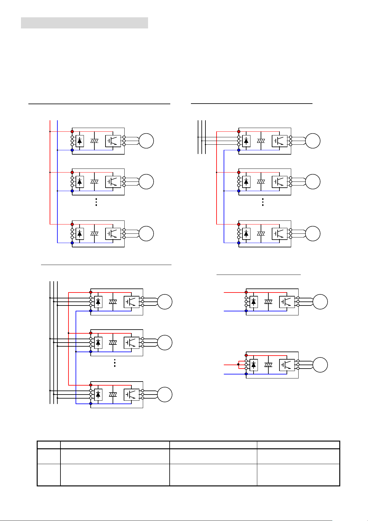
[1] Connection method
There are several ways for DC bus connection of the inverters. (Examples of 3-phase 200V or 400V class inverter.)
Case 1 : Connected in parallel to a common DC bus
DC power
supply
INV #1
M 1
INV #2
M 2
INV #n
M n
Case 3 : AC & DC Connected together
AC power
supply
Case 2 : Connected in parallel to an A-fed inverter
AC power
supply
INV #1
+
M 1
INV #2
M 2
INV #n
M n
DC supply connection methods
+
-
+
-
ΠConnecting to + and - terminal
+
-
• Connecting to AC inputs and - terminal
Ø Advantage and disadvantages of each connection method.
Item Contents Advantage Disadvantage
Connecting to + & - terminal Ÿ No concern for the
Œ
Connecting to AC inputs and - terminal Ÿ Integrated inrush current
•
rectifier bridge diodes.
limiting circuit is used.
Ÿ There will be no inrush
current limiting.
Ÿ Rectifier bridge diodes
of the main inverter may
need to be up-sized.
Page 3

[2] DC voltage to be supplied
Big inrush current at
INV #1
M 1
INV #2
M 2
INV #n
M n
UV level
Supplied DC voltage should be between the UV voltage and the OV voltage (or BRD ON level) of the inverter.
Model name UV level BRD ON level OV level (regen.) OV level (source)
J100 200V class 140Vac ~ 160Vac (V-SET) +137.5V
400V class 280Vac ~ 320Vac (V-SET) +275V
J300 200V class 140Vac ~ 160Vac (AVR set) +138V 369Vdc ~ 404Vdc
400V class 280Vac ~ 320Vac (AVR set) +276V 756Vdc ~ 827Vdc
L100 200V class
400V class
SJ100 200V class 370Vdc +4%,-3%
400V class
L300P 200V class
400V class
SJ300 200V class
400V class
190Vdc ± 10Vdc 395Vdc ± 20Vdc
395Vdc ± 20Vdc
Same as L100
200Vdc ± 10Vdc 395Vdc ± 10Vdc
400Vdc ± 20Vdc
Same as L300P
740Vdc +4%,-3%
-
-
Adjustable by
[b096]
390Vdc ± 15Vdc
780Vdc ± 30Vdc
Aprx. 365Vdc for 100s
790Vdc ± 40Vdc
Same as L100 Same as L100
790Vdc ± 20Vdc
Same as L300P Same as L300P
Aprx. 730Vdc for 100s
Aprx. 380Vdc for 60s
Aprx. 760Vdc for 60s
Ø If it is higher, inverter may trip with OV or BRD error.
Ø If it is lower, inverter may trip with UV.
[3] Cautions
Case 1 : Connected parallel to a common DC net
power ON
DC power
supply
Main power (AC)
For Cases 2 & 3
OFF
Ø Take preventive measures to limit inrush current at power ON,
since the integrated inrush current limiting circuit is not used.
à Otherwise there will be a unexpected UV at net side or
damage to the inverter caused by ∆V=di/dt.
Ø Use DC chokes for each inverter to avoid interaction due
to surge and/or harmonics.
à Otherwise there may be an unexpected failure of the
inverter or other attached equipment.
Ø Take preventive measures to ensure sufficient time between UV
level and dead voltage of the DC/DC converter (*1) at power
OFF. This is to allow ample time for EEPROM to store
the existing data at power OFF. (∆t ; see below)
à Otherwise there is a possibility of an EEPROM error at
the next power ON.
DC bus voltage
For Cases 1~3
DC-DC conv.
(internal 5V)
EEPROM store
period
Threshold voltage of DC-DC converter
(This value depends on the inverter model.
∆t
Around 0.5~1s or more
But in general it is around 100Vdc)
(*1) The required time depends on the parameters
which have changed before power OFF.
Page 4

Case 2 : DC Bus connected n parallel to a single AC-fed inverter
INV #2
M 2
INV #n
M n
INV #1
M 1
AC power
supply
+
i
M1
-
i
M2
i
Mn
(*2) Capacity of the main inverter
Rated current of the main inverter should be higher than;
Ø Total rated current of the inverters
and
Ø Possible highest total motor current
Ø Pay attention to the selection of the main inverter
(#1) because all the input current flows through
the rectifier bridge of this inverter. (*2)
Ø Need sufficient time for EEPROM to store the data.
(Refer to Case 1)
Ø Use DC choke. (Refer to Case 1)
<Selection of the main inverter kW>
Input current
AC input
=
ii
∑
ks
1
=nk
2
i
2
i
n
[Example of 4 inverters in parallel]
Ø INV#1~#4=SJ300-040HFx (8.6A rated)
Ø i
M1(max)
= i
M2(max)
= i
M3(max)
= i
M4(max)
= 9.0Arms
In this case, the total motor current under the possible worst case is higher than that of the inverters.
Total inverter rated current = i1 + i2 + i3 + i
Total motor current under possible worst case = i
M1( max)
+ i
= 8.6 * 4 = 32.2 Arms
4
M2(max)
+ i
M3(max)
+ i
M4(max)
à Main inverter must therefore be SJ300-185HFx (38A) or larger. SJ300-220HFx is suggested
to provide additional safety margin.
= 36Arms
 Loading...