

Page 1

SJ300 Series Inverter
Application Note:
Optimizing Vector Control
Hitachi America, Ltd.
AN072302-1
Please refer also to the SJ300 Inverter
Instruction Manual and the SJ-FB Option
Board Instruction Manual
© 2002 Hitachi America, Ltd.
Page 2

Application Note for Vector Control with the SJ300 Inverter
2
© 2002 Hitachi America, Ltd.
Contents
[1] Overview
[2] How to Tune Each Parameter
(2-1) Tuning target of each parameter
(2-2) SLV Control block diagram
(2-3) V2 Control block diagram
(2-4) Standard motor parameter settings for SJ300 (400V class EU version) series inverter
(2-5) Example of tuning effects (SLV mode)
[3] Positioning Under ASR mode (Orientation Function)
(3-1) Orientation Function
(3-2) Example of positioning under speed control mode (ASR) on SJ300 with SJ-FB
(3-2-1) Example of wiring
(3-2-2) Example of parameter settings
(3-2-3) Timing chart
[4] APR Control
(4-1) Example of parameter settings
(4-2) How to adjust control parameters for APR control
[5] Master Slave Control
(5-1) Example of parameter settings for Master-Slave control
(5-2) How many slaves can be connected?
(5-2-1) Parallel connection
(5-2-2) Series connection
(5-3) Explanation of each P parameter
(5-4) Explanation of each output related to V2 control
Appendix A Calculation of total inertia (reflected to the motor shaft)
(A-1) Ventilation Fan
(A-2) Truck
(A-3) Conveyer
Appendix B Calculation of load inertia
(B-1) A column
(B-2) A cylinder
(B-3) A rectangular solid
(B-4) A Cone
(B-5) Wind up (vertical linear motion)
(B-6) Horizontal linear motion
This document is a guideline for optimizing motor/inverter performance in vector mode through
parameter adjustments. Please note that actual performance of the motor depends on a combination
of many parameters, and is difficult to describe concisely. Trial & error is the customary means to
achieve good motor performance. Therefore please regard this information as just a guide only.
This document only shows technical issues related to vector control. Please refer to the SJ300
Inverter and SJ-FB manuals for detailed information for installation and operation.
Page 3
[1] Overview
ASR
Slip reference
Frequency
q axis current
Slip reference
Speed
Change over
Stability
1/s
d-axis current
d-axis
q-axis
Estimation of
Estimation of
calculation of
Output
Estimation of
3
© 2002 Hitachi America, Ltd.
This engineering note applies when using SLV , 0-SLV and V2 (closed loop) control. It is often difficult to
get optimized motor performance because many parameters interact. Please refer to this document for
getting a rough idea how to achieve good motor performance with above control modes. Please also note that
the performance WILL NOT BE like a servo drive even in the case of V2 mode.
There are 3 basic modes with which you can get high torque performance with the SJ300 inverter:
(1) SLV control (No SJ-FB is used)
High motor torque performance with open loop can be obtained in the low frequency range (~0.5Hz).
Please refer to a standard SLV block diagram in Fig 1 (section 2-2).
[H***] parameters are mainly adjusted for the control.
(2) 0-SLV control (No SJ-FB is used)
High torque performance can be obtained at around 0Hz. This does NOT mean the motor shaft will be at a
standstill. The motor rotates slightly to generate motor torque, since this is not a servo drive. Depending on the
application and tuning, you may be able to get full torque with the motor at standstill. This control algorithm is
different from SLV control.
[H***] parameters are mainly adjusted for the control.
ΠFrequency control block portion
reference
ωr*
+
-
(PI)
reference
ωr^
Iq*
+
estimation
of control
• Voltage control block portion
Magnetizing current
id*
Torque current
iq*
reference
+
id**
+
-
-
ω
s
+
+
ωs*
at 0Hz
q-axis flux
∆E
d
i
d
1
i
q
q
ACR
ACR
∆V
ω
∆V
Output frequency
+
+
control
d
Voltage Vector
ω
1
+
Motor torque
Output phase
Flux
+
+
Vd*
Vq*
+
+
V
d
voltage
V
q
i
i
q
Feedback current
d
(3) V2 control (SJ-FB is used)
High torque and stable, accurate motor performance can be achieved with the SJ300 in vector mode.
A motor encoder and a feedback option card for SJ300 (SJ-FB) are needed to use this control mode.
There are two regulation modes within the V2 control mode: ASR mode and APR mode .
ΠASR mode : Inverter is controlled by speed command input (digitally set, analog input, or RS485)
• APR mode : Inverter is controlled by pulse train input signal
[H***] and [P***] parameters are adjusted for achieving good motor control.
A suitable mode should be selected depending on the application.
Page 4
[Difference between each control]
4
© 2002 Hitachi America, Ltd.
Ø Control performance
Item SLV mode V2 mode
Speed linearity <1 % <0.01 %
Speed fluctuation <1 % <0.01 %
Control range 1 : 50 1 : 100
Speed response 15 rad/s 60 rad/s
Torque control range 1 : 50 1 : 100
Torque response 50 rad/s 500 rad/s
s Note: These are representative values only.
s
Percentages are relative to base speed
Ø Torque performance at low speed
Item SLV control 0-SLV control V2 control
Down sized motor 150% or more 150% or more 150% or more
Same kW motor 100% or more 100% or more 100% or more
s These are guaranteed minimum values with a Hitachi standard induction motor. Actual capability is greater.
Ø Torque performance at 0Hz
Item 0-SLV control V2 control
Down-sized motor 150% or more
with a small slip
Same kW motor 100% or more
with a small slip
150% or more
with standstill
100% or more
with standstill
s This has been confirmed using Hitachi standard induction motor and J2 motor (for V2 control).
Page 5
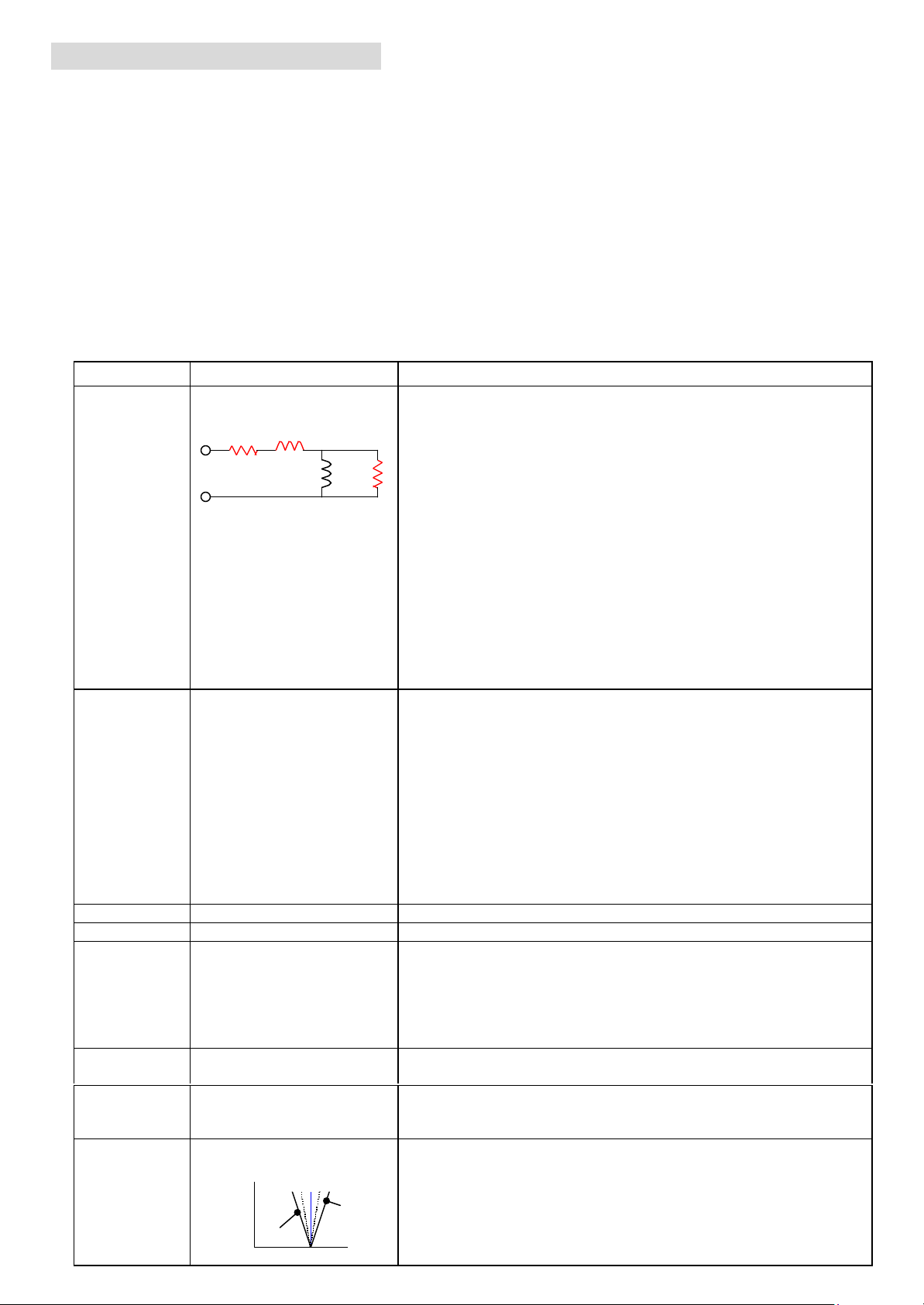
[2] How to tune each parameter
Equivalent circuit of one leg of
Small
5
(2-1) Tuning target of each parameter
There are many parameters, which influence the motor performance in SLV, 0-SLV & V2 control modes.
In some cases auto tuning is not fully sufficient to get the best motor performance because there are
various kinds of motors in the world. It is sometimes necessary to adjust by hand after the auto tuning.
Generally the performance of the motor can be determined from two criteria:
Ø Torque performance at low speed
Ø Speed response against target speed
Table 1 shows main parameters that influence the motor performance inSLV mode. The concept is the same
in 0-SLV and V2 modes as well.
Table 1. Explanation of parameters related to motor performance in SLV mode
Code Function Remarks
H001 Auto tuning mode This determines the method of auto tuning.
00 (NOR) : Auto tuning invalid
R1 L
the motor winding
R2
LM
01 (NRT) : Auto tuning with motor at standstill
02 (AUT) : Auto tuning with motor rotation
Auto tuning determines the following motor constants
automatically. (See left figure as well.)
Ÿ R1 (primary resistance)
Ÿ R2 (secondary resistance)
Ÿ L (leakage inductance)
Ÿ Io (magnetizing current at base frequency)
Ÿ J (total load inertia)
Normally better motor performance can be obtained by auto tuning
with motor rotation with an actual load on the motor. But if the
system does not allow rotating the motor, like a lift application for
example, auto tuning with motor at standstill can be used.
H002 Motor constant selection This determines which set of motor parameters is used by the drive.
00 : Motor parameters for a Hitachi standard motor
(Uses [H020] ~ [H024] )
01 : Use auto tuning data
(Uses [H030] ~ [H034] )
02 : Use auto tuning data with On-line auto tuning
On-line auto tuning occurs every time the inverter stops. It
measures R1 and R2, the main values that may change
due to a motor temperature change. The tuning period is roughly
5 seconds maximum, and if the RUN command is given during
the tuning routine, the inverter will start and tuning is aborted.
H003 Motor kW This sets the motor kW, not a kW of an inverter.
H004 Motor poles
H005
H006 Motor stability control factor This should be adjusted in case of motor instability.
H020 / H030 Primary resistance of the
H021 / H031 Secondary resistance of the
Speed response factor K
motor R1 [Ω ]
motor R2 [Ω ]
Torque
ideal
Big R2
R2
Controls the speed response
Ÿ
Large K à Quick response (Too high a value can cause instability.)
Ÿ Small K à Slow but stable response
Value is also dependent on Proportional gain (P-gain : [H050])
and Integration gain (I-gain : [H051]). ( K = f(Kp, Ki) ).
Increase / decrease depends on the situation.
Influences mainly the torque at low speed.
Ÿ Large R1 à Higher torque (Too high R1 à Over magnetizing)
Ÿ Small R1 à Smaller torque
Influence mainly on the speed change ratio (= slip compensation)
Ÿ Large R2 à Increase speed change ratio
(= Actual speed becomes faster than a target speed.)
Ÿ Small R2 à Decrease speed change ratio
(= Actual speed becomes slower than a target speed.)
Speed
Page 6

Code Function Remarks
6
See Remarks for H050
© 2002 Hitachi America, Ltd.
H022 / H032 Leakage inductance of the
motor L [mH]
H023 / H033 Magnetizing current of the
motor Io [A]
L does not influence control much compared to other
parameters, however a suitable value is recommended to be set.
Influences mainly the torque at low speed.
Ÿ Large Io à Bigger torque (Too big Io à Over magnetizing)
Ÿ Small I
à Smaller torque
o
H024 / H034 Total inertia J [kgm2] Influences mainly speed and torque response performance
This should be the total inertia (Σ J) on the motor shaft,
including the inertia of the rotor of the motor and the load. See
table 2 for information on how to tune in each case.
à
See appendix A for calculation of the total inertia.
H050 Proportional gain under
PI control mode (Kp)
(% based on [H005])
H051 Integration gain under
PI control mode (K
)
i
(% based on [H005])
Fine tuning of proportional portion of speed response factor.
Ÿ Large Kp àQuick response (Too high Kp can cause instability.)
Ÿ Small K
à Slow but stable response
p
Fine tuning of Ki portion of speed response factor.
Ÿ Large Ki à Quick response (Too high Ki can cause instability.)
Ÿ Small K
à Slow but stable response
i
H052 Proportional gain under
P control mode (Kp)
(% based on [H005])
F002 Acceleration time
F003 Deceleration time
Acc and Dec time influence the response. Even if
optimized tuning parameter values are set, actual motor speed will
change according to the set ramp time.
If a quick response is required, the ramps should be set as fast as
possible. Or, use LAC (LAD cancellation) to make the ramp invalid.
A044 Control mode Control mode should be set to 03 (SLV), 04 (0-SLV) or 05 (V2).
A045 Output gain (Vgain ) Output gain scales the duty cycle of PWM output, regardless of
the input voltage of the inverter.
Decreasing output gain can solve the problem of motor instability,
however the output torque will also decrease in this case.
A081 AVR function AVR function attempts to maintain a stable output voltage by
changing the duty cycle of the PWM output in real-time. If the input
voltage changes or bus voltage changes due to regeneration, motor
sees constant voltage. That means the motor efficiency will be better.
In some cases, disabling the AVR function can resolve motor
instability problems.
AVR function attempts to always mainain constant output voltage.
During operation, DC bus voltage is always changing, which
means AVR function is always acting to change the duty cycle of
PWM output voltage. Since it is an active control function it may
lead sometimes motor instability (unstable energy transmission).
In such cases, setting AVR OFF can solve the problem.
b022 OL restriction level Set OL level [b022] as high as possible, or else disable it
(set [b021] to “00 ”), because a rather high motor current is
required in low frequency area in the case of vector control.
b041~b044 Torque limit level Set torque limit level as high as possible, or else disable it
b083 Carrier frequency
* Second and 3rd functions ([H2**] & [H3**]) have the same meaning for 2nd and 3rd motors.
Refer to Table 3 for standard (default) motor parameter settings for SJ300 series inverter.
High torque cannot be achieved if OL restriction is preformed.
( = assign TL to an intelligent input terminal and leave it OFF),
because high motor current is required in the low frequency area
in the case of vector control.
Maximum torque cannot be achieved if torque limit is triggered.
Decreasing carrier frequency can solve the problem of motor
instability.
This is because the effect of dead time will be reduced.
Page 7

Table 2 shows suggestions for adjusting the SLV and other related parameters to correct various phenomena.
7
© 2002 Hitachi America, Ltd.© 2002 Hitachi America, Ltd.© 2002 Hitachi America, Ltd.
Table 2. Suggestions for tuning
# Phenomena Parameter How to adjust
Actual speed is faster than the target speed.
1
(Speed deviation is +)
Actual speed is slower than the target speed.
2
(Speed deviation is - )
Insufficient torque at low speed (~ few Hz) H020
3
4 Shock at start H024 Decrease J
5 Unstable motor rotation H005 Decrease speed response factor
Insufficient torque at low speed due to torque
6
limit action
H021
H021
H023
H024 Decrease J
H006
A045 Decrease output gain
A081 Set AVR function to OFF
b083 Decrease carrier frequency
b021,
b041
~b044
H005 Increase speed response factor
Decrease R2 value
(Minimum target is 80% of the preset value)
Increase R2 value
(Maximum target is 120% of the preset value)
Increase R1 value
(Maximum target is 120% of the preset value)
Increase Io value
(Maximum target is 120% of the preset value)
Increase / decrease stability control factor
(Increase or decrease depends on the situation.)
Set;
Torque limit level > Overload restriction level
7 Response is slow
Speed
8
response
overshoot due to too quick
H050 Increase P-gain of speed response factor
H051 Decrease I-gain of speed response factor
H005 Decrease speed response factor
H050 Decrease P-gain of speed response factor
H051 Increase I-gain of speed response factor
*Refer to Table 3 for a standard (default) motor parameter settings for SJ300 series inverter.
Page 8

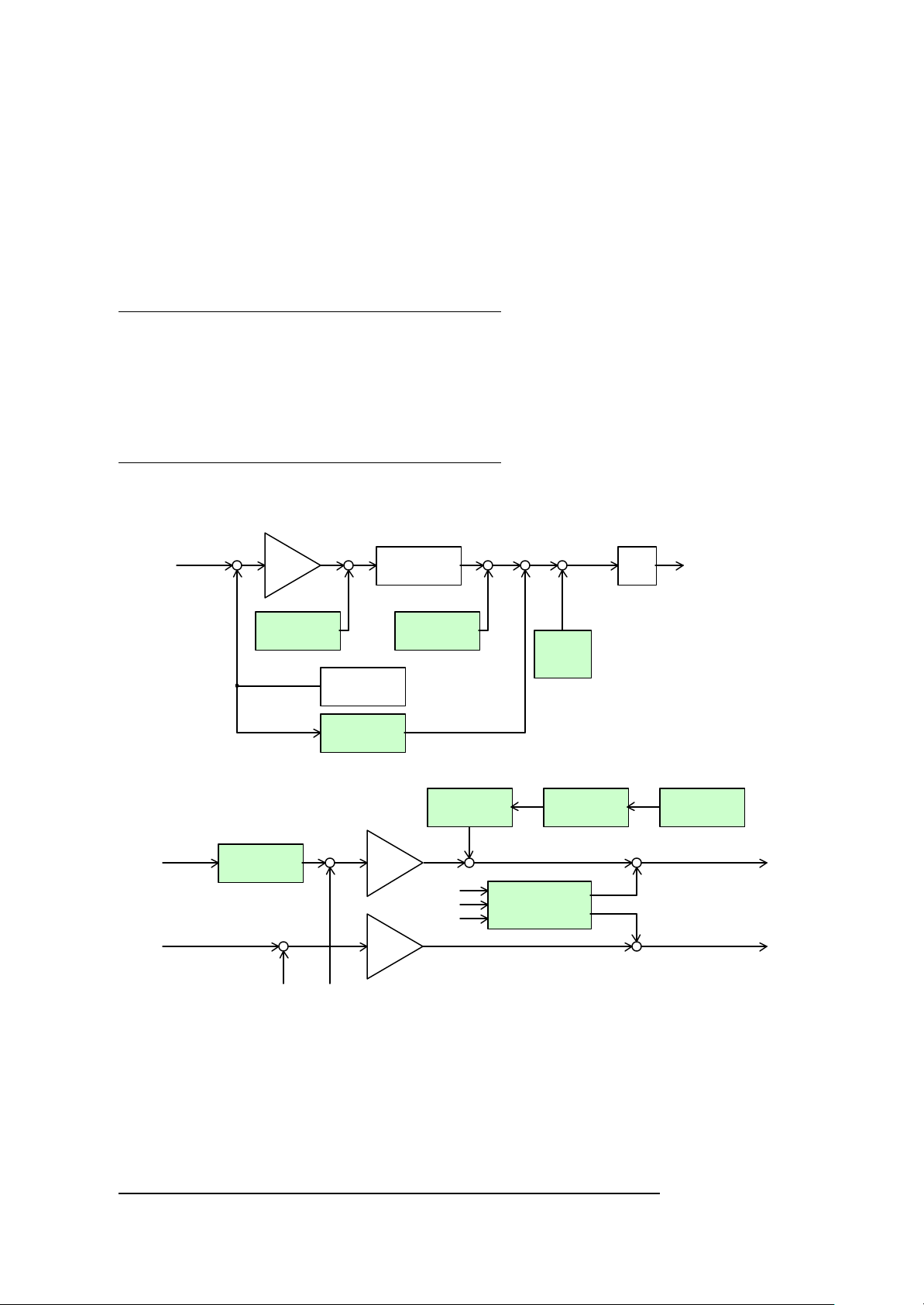
SLV Control block diagram (Fig 1)
Magnetizing
Speed response [H005]
Magnetizing
Stabilization
Motor Constant
Motor Constant
Motor Constant
Motor Constant
Motor Constant
Motor Constant
8
© 2002 Hitachi America, Ltd.
ωr*
Speed reference
ωr^
id*
current reference
Speed
control
P gain for PI [H050]
I gain for PI [H051]
P gain for P [H052]
[H070], [H071], [H072]
Motor Constant (R1,L,Io,J)
iq*
(R1, R2, L, Io)
(R1, R2, L, Io)
iq*
id*
φd*
Voltage calculation
(Interference control)
vq*
vd*
Motor
vU* vV* vW*
Voltage conversion
(2φà3φ)
current Io
(R1, R2, L, Io)
iq*
Torque current
i
q
id*
Magnetizing
current control
i
d
d-axis secondary
id*
flux control
control
(q-ACR)
(d-ACR)
(R1, R2, L, Io)
∆
Vd∆
V
q
ω1*
∆vq0
θ
Compensation
voltage
calculation
(R1, R2, L, Io)
∆vd0
factor [H006]
iq*
φd* ω1* θ
ωr^
Frequency
calculation
φd*
Speed
estimator
i
q
ω1*
Integrator
i
d
Current converter
i
q
(3φà2φ
)
IwIu
θ
Iu
Iw
(R1, R2, L, Io)
Vector control technical information
Page 9
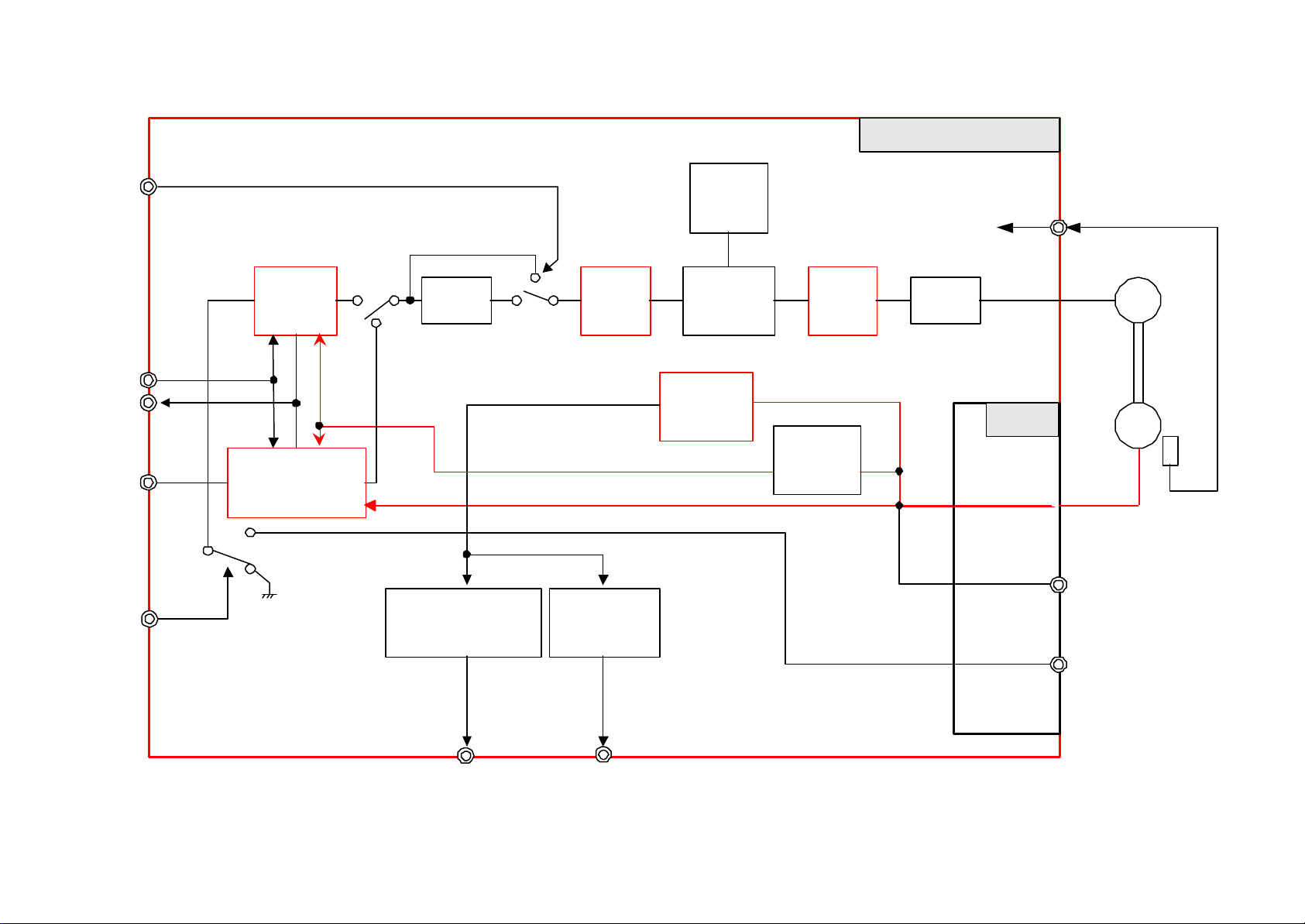
LAC
9
© 2002 Hitachi America, Ltd.
SJ-FB Option Board Block Diagram
Internal
setting
Inverter main body
TH
PCLR
POK
ORT
STAT
APR
Orientation
control
LAD
Speed deviation
excessive signal
DSE ZS
ASR
Zero speed
detection
Torque
limiter
Speed
detection
ACR
Position
detection
PWM M
SJ-FB
EAP,EAN
EBP,EBN
EZP,EZN
EP5,EG5
AP,AN
BP,BN
SAP,SAN
SBP,SBN
EC
Page 10

0.4kW
0.75kW
1.5kW
2.2kW
4kW
5.5kW
7.5kW
11kW
15kW
18.5kW
22kW
30kW
37kW
45kW
55kW
75kW
90kW
110kW
132kW
R1
24.584
9.404
3.588
2.368
1.124
0.820
0.512
0.368
0.240
0.156
0.148
0.088
0.072
0.052
0.032
0.024
0.016
0.012R26.880
2.520
1.776
1.032
0.400
0.272
0.236
0.184
0.112
0.104
0.112
0.084
0.072
0.036
0.040
0.028
0.024L83.28
24.84
13.64
7.88
7.36
5.16
2.88
2.40
2.28
1.88
Io
5.10
11.25
7.97
10.53
16.18
18.51
21.25
27.00
31.50
35.00
36.17
44.00
47.002pJ
0.003
0.011
0.012
0.039
0.049
0.059
0.095
0.116
0.276
0.313
0.551
0.613
0.713
3.001
3.438
4.625
5.625
R1
22.800
11.936
4.496
3.604
1.600
0.960
0.608
0.520
0.320
0.160
0.132
0.104
0.080
0.060
0.036
0.028
0.024
0.016
R2
11.092
3.152
1.808
0.996
0.684
0.416
0.300
0.228
0.148
0.108
0.104
0.080
0.068
0.044
0.032
0.032
0.024
L
130.56
25.12
18.64
12.60
11.28
10.40
7.44
5.16
3.64
2.40
2.32
1.92
Io
7.64
9.91
12.70
18.51
24.08
28.33
33.33
45.16
50.00
54.33
50.00
57.334pJ
0.005
0.017
0.027
0.072
0.088
0.111
0.176
0.213
0.476
0.601
1.038
1.138
1.376
3.001
3.438
6.000
7.000
R1
15.332
10.156
5.028
2.804
1.268
1.000
0.872
0.552
0.300
0.212
0.148
0.112
0.104
0.060
0.044
0.036
0.024
0.020R27.200
3.252
2.100
0.880
0.640
0.500
0.308
0.240
0.156
0.108
0.096
0.076
0.056
0.048
0.048
0.024
0.020
L
109.16
37.60
33.04
26.56
24.36
22.88
5.96
5.72
4.00
2.76
2.32
1.88
Io
6.30
11.16
14.33
20.25
28.96
33.33
38.90
43.17
58.33
58.00
81.00
68.006pJ
0.009
0.031
0.062
0.151
0.176
0.276
0.363
0.688
0.938
1.626
1.876
2.126
4.376
5.251
7.875
9.750
25.625
R1
26.668
10.244
3.532
1.708
1.000
0.900
0.804
0.536
0.412
0.232
0.168
0.092
0.060
0.052
0.040
0.024
0.020
0.016
R2
15.200
2.656
1.900
1.260
1.120
1.020
0.392
0.300
0.188
0.160
0.132
0.080
0.068
0.064
0.040
0.036
0.032
L
142.84
59.44
36.36
27.44
25.36
23.44
9.84
6.68
4.32
3.44
3.00
2.08
Io
8.40
11.97
17.66
26.73
34.83
33.80
47.50
51.33
59.33
67.00
91.47
109.178pJ
0.017
0.062
0.126
0.226
0.276
0.363
0.801
0.938
1.876
2.126
6.376
9.251
12.001
15.001
25.625
25.625
25.625
10
© 2002 Hitachi America, Ltd.
Typical Motor Constants
6.048
47.56
0.75 1.17 2.61 2.43
0.005
6.392
51.88
0.90 1.26 2.19 4.37
0.009
5.496
57.36
1.26 1.78 3.01 4.64
0.017
6.632
78.04
1.44 2.34 4.25 6.75
0.031
6.44 5.28
9.21
6.57 8.25
7.20 8.37
8.52 8.63
0.192
0.140
4.12
12.91
0.126
0.204
0.180
4.12
16.66
0.413
0.268
0.188
4.76
16.73
0.813
0.320
0.244
6.00
19.91
1.626
1.48 1.00 0.80 0.72 0.60
1.48 1.00 0.96 0.76 0.68
1.52 1.16 1.04 0.72 0.68
1.76 1.44 1.08 0.88 0.72
These parameters are based on EU motors, which have slightly different motor constants than Japanese & US motors.
Therefore the Japanese versions and US versions of SJ300 have slightly different motor parameters as default settings.
Page 11

(2-5) Example of tuning effects (SLV mode)
Data00. Default parameter
Data01. Carrier frequency 5kHzà0.5kHz / 15kHz
11
© 2002 Hitachi America, Ltd.
This section shows examples of actual effects when changing each parameter by showing motor current
waveforms. Please note that these are just examples. Actual motor performance will depend on the application.
This data is reference only! It is only intended as a guide for obtaining optimal performance.
<Summary of examples>
Common condition
Ø INV : SJ300-007HFE (rated output current = 2.5A)
Ø Motor : Hitachi standard induction motor (380V 50Hz 0.75kW 1.9A 4p 1420rpm) No load (shaft free)
s Set frequency [F001] = 3.00Hz
s Acceleration time [F002] = 0.01s, Deceleration time [F003] = 0.01s
s Control mode [A044] = 03 ; SLV mode (open loop)
s All others are default settings
Parameter
Default parameter
comparison Data number Remarks
Data00
b083 : Carrier frequency 5.0 kHz 0.5 kHz
Data01
15 kHz
H003 : Motor kW 0.75 kW 75kW Data02
H004 : Motor poles
H005 : Speed response factor K
H020 : Motor R1
H021 : Motor R2
H022 : Motor L 51.88 mH 10.00
H023 : Motor Io 1.26 A 0.3
H024 : Total J
H050 : P-gain of K
H051 : I-gain of K
4 8 Data03 OC trip
1.590 0.100
11.93
Ω
6.392
Ω
0.009 kgm
2
100 % 1
100% 1
10.00
3.000
30.00
3.000
30.00
200.0
3.0
0.001
0.100
500
200
Data04
Data05
Data06
Data07
Data08
Data09
Data10
Data11
Shock at start
OC trip
OC trip
Shock at start
Note - the graphs show steady state operation for comparison purposes only. Response characteristics cannot
be determined from this data.
1 >
1) Ref A: 1 A 200 ms
Actual frequency (average) f(ave) = 2.88Hz
IM = 1.38Arms
1 >
2 >
3 >
1) Ref A: 2 A 200 ms
2) Ref A: 2 A 200 ms
3) Ref A: 2 A 200 ms
f (ave) = 2.92 Hz / 2.88Hz
IM = 1.42 Arms / 1.38
fc = 15kHz
fc = 0.5kHz
Default parameter
Vector control technical information
Page 12

1 >
Data05. R1 [H020] = 11.93 à 3.000 / 30.00
K effects on the response so there is almost no
Data06. R2 [H021] = 6.392 à 3.000 / 30.00
12
© 2002 Hitachi America, Ltd.© 2002 Hitachi America, Ltd.
[H004] = 8
[H003] = 75
1 >
Default parameter
2 >
1) Ref A: 2 A 200 ms
2) Ref A: 2 A 200 ms
Data02. Motor kW [H003] = 0.75kW à 75kW
f (ave) = 0.87 Hz
IM = 1.57 Arms
[H005] = 10
1 >
2 >
3 >
1) Ref A: 2 A 200 ms
2) Ref A: 2 A 200 ms
3) Ref A: 2 A 200 ms
[H005] = 0.1
Data04. K [H005] = 1.590 à 0.1 / 10
f (ave) = 3.08 Hz / 2.97 Hz
IM = 1.38 Arms / 1.38 Arms
2 >
1) Ref A: 2 A 200 ms
2) Ref A: 2 A 200 ms
Default parameter
Data03. Motor poles [H004] = 4p à8p
OC trip after few seconds.
R1 = 3.00
2 >
1 >
3 >
1) Ref A: 2 A 200 ms
2) Ref A: 2 A 200 ms
3) Ref A: 2 A 200 ms
Default parameter
R1=3.00 à Bad motor performance
R1=30.0 à OC trip at start
R1 = 30.0
difference in steady state current waveform.
R2 = 30
1 >
2 >
3 >
1) Ref A: 2 A 200 ms
2) Ref A: 2 A 200 ms
3) Ref A: 2 A 200 ms
R2=3.0
Default parameter
f (ave) = 2.94 Hz / 4.25 Hz
IM = 1.37 Arms / 1.34 Arms
L=200.0 mH
1 >
2 >
3 >
1) Ref A: 2 A 200 ms
2) Ref A: 2 A 200 ms
3) Ref A: 2 A 200 ms
L=10.0 mH
Default parameter
Data07. L [H022] = 51.88 à 10.00 / 200.0
f (ave) = 2.96 Hz / 2.79 Hz
IM = 1.37 Arms / 1.40 Arms
Page 13

1 >
Data09. J [H024] = 0.009 à 0.001 / 0.100
13
© 2002 Hitachi America, Ltd.
J = 0.1
Io = 3.0 A
1 >
J = 0.001
2 >
Io = 0.3 A
3 >
1) Ref A: 2 A 200 ms
2) Ref A: 2 A 200 ms
3) Ref A: 2 A 200 ms
Default parameter
Data08. Io [H023] = 1.26 à 0.30 / 3.00
f (ave) = 2.98 Hz / -
IM = 0.40 Arms / - (OC trip)
1 >
Kp = 200
2 >
3 >
1) Ref A: 2 A 200 ms
2) Ref A: 2 A 200 ms
3) Ref A: 2 A 200 ms
Default parameter
f (ave) = 2.61 Hz / -
IM = 2.29 Arms / - (OC trip)
1 >
Ki = 200
2 >
Kp = 10
1) Ref A: 2 A 200 ms
2) Ref A: 2 A 200 ms
Data10. Kp [H050] = 100 à 10 / 200
Shock at start and then OC trip
2 >
Ki = 10
1) Ref A: 2 A 200 ms
2) Ref A: 2 A 200 ms
Data11. Ki [H051] = 100 à 10 / 200
Shock at start and then OC trip
Ø Note that these plots were made under steady state conditions, i.e. not transient data.
Transient response cannot be determined from these plots.
Ø There is no set procedure or specific order for these tuning steps, because optimal tuning depends on
the conditions and situation of the system. Refer to Table 2 in previous section for suggestions for tuning.
Page 14

[3] Positioning under ASR mode (Orientation function) (V2 mode)
Orientation speed [P015]
0
14
© 2002 Hitachi America, Ltd.
This can be implemented using SJ-FB ( feed back option card ).
(3-1) Orientation Function
The SJ300 series incorporates a function where the inverter counts the pulses from the motor encoder
and stops after a certain number of pulses. It is called the orientation function.
The Orientation function is used when an accurate stop position is required.
The SJ300 does not count encoder pulses every time, which means it is different from servo drives. The SJ300
starts counting the encoder pulses only after the Z pulse is given during orientation mode. Therefore the
SJ300 can stop the motor at a certain position.
s First, it is necessary to go into the orientation mode. (Turn the “ORT ” terminal ON on the logic
card.) During orientation period, INV stops the motor after certain pulses from Z pulse is given.
<Example of stopping 7pulses after Z pulse is given>
Orientation mode Positioning mode
ORT input
Z pulse
(1 pulse / rotation)
A pulse
• ‚ ƒ „ … †
‡
Stop!
fout
Fig 3. Example of positioning
Parameter set for this example under following condition is in table below .
- 1024 ppr encoder
- 2.0 Hz of orientation speed
- acceptable positioning range is 7±3 pulses
- give frequency command from the analog input (O-L)
- give RUN command from the digital panel
s Orientation mode starts
when the actual output
frequency reaches
the orientation speed.
s Deceleration to the
orientation speed is based on
the set deceleration time.
The ramp is based on the position loop
gain [P023], and does not follow the set
ramp time [F003].
Big [P023] results in a quick stop.
No. Code Contents Set value Remarks
1 A044 Control method 05 V2 (closed loop control)
2 P011 ppr of the encoder 1024 Depends on the encoder
3 P012 Control mode 00 ASR (Speed command base on speed)
4 P013 Mode of the pulse train input - No need to care because this is ASR mode
5 P014 Stop position while orientation 28 [P014] = 4096 * 7 / 1024 = 28
6 P015 Speed while orientation 2.0 In case of 2.0Hz for orientation speed.
7 P016 Direction of orientation 00 In case of FW rotation
8 P017 Orientation completion range 12 Allowable deviation of positioning.
9 A001 Frequency command from; 01 Terminal (O-L input)
10 A002 RUN command from; 02 “RUN” key of the operator
F002 Acceleration time 3.011
F003 Deceleration time 3.0
[P017] = 3 * 4
(Multiplying 4 is fixed as MCU calculation)
As short as the system allows.
Page 15

(3-2) Example of positioning under speed control mode (ASR) on SJ300 with SJ-FB
Belt is stopped at a certain position after passing a switch “SWZ”.
M
Required stop
SW
15
© 2002 Hitachi America, Ltd.
(3-2-1) Example of wiring
SJ300
f*
Material
O
L
P24
ORT
M
EP5
EG5
EAP
EAN
EBP
EBN
EZP
EZN
Œ
Ž
•
Allowable
deviation
n0 (pulses)
Encoder
Example of 1024ppr line driver type encoder.
EZP
EZN
n (Pulses)
•
position
In case of using external Z pulse
A
Œ Material M passes “SWO” point.
(“SWO” turns ON which means an inverter is going into an
orientation mode.)
•
Belt speed will be an orientation speed (set in
[P015]), which means it is ready for positioning
and wait for a Z pulse.
Ž After passing SWZ point, inverter starts counting the pulses
and stops at a certain position (set in [P017]).
• Inverter gives out a “positioning completion signal ; POK” from
an intelligent output terminal.
Fig 4. Example of wiring
(3-2-2) Example of parameter settings
No. Code Contents Set value Remarks
1 A044 Control method 05 V2 (closed loop control)
2 P011 ppr of the encoder 1024 Depends on the encoder
3 P012 Control mode 00 ASR (Speed command base on speed)
4 P013 Mode of the pulse train input - No need to care because this is ASR mode
5 P014 Stop position while orientation * When you want to stop at n pulses after
catching zero-pulse (after AZP/N is given);
[P014] = 4096 * n / [P011]
<Regardless the ppr of an encoder>
Stop at 300 pulses after Z pulse is given
for example;
[P014] = 4096 * 300 / 1024 = 1200
6 P015 Speed while orientation 2.0 In case of 2.0Hz for orientation speed.
7 P016 Direction of orientation 00 In case of FW rotation
8 P017 Orientation completion range * Allowable deviation of positioning.
[P017] = no * 4
9 A001 Frequency command from; 01 Terminal (O-L input)
10 A002 RUN command from; 02 “RUN” key of the operator
11 F002 Acceleration time 3.0
F003 Deceleration time 3.0
Above are the main parameters to get position control. You have to adjust other parameters ([H***] parameters)
to get good performance.
As short as the system allows.
Page 16

(3-2-3) Timing chart
ORT
Motor
N
Positioning
signal (POK)
16
© 2002 Hitachi America, Ltd.
rotation
Œ
•
2Hz Orientation
•
input
Z
A
B
MCU recognition
completion output
ON
Ž
Positioning start signal (Min. ON period = 50ms)
Start counting the pulses from the falling edge
1 2 n-2 n-1
n
Fig 5. Timing chart of example 3-2
Motor shaft rotates a bit to reverse in case it exceeds the stop position (1 ~ 2 pulses).
Refer to section [2] for adjusting each parameters to get good motor performance.
Page 17

[4] APR Control
A, B phase pulse train input
Voltage
Pulse train
APR
ASR
ACR
εθ*ω*
i*
ω
θ
i
17
© 2002 Hitachi America, Ltd.
You can control the motor by a pulse
train input on SJ300 with SJ-FB.
Make STAT terminal ON to get
(90 degrees of phase difference)
0
SJ300
EP5
EG5
M
Encoder
started. (Inverter starts to accept pulse
EAP
train input after STAT is turned ON.)
0
0
0
SAP
SAN
SBP
SBN
P24
STAT
EAN
EBP
EBN
EZP
EZN
Fig 6. Idea of APR control
SJ300 controls the motor based on the pulse train input to SAP, SAN, SBP, SBN which are 90 degrees phase
difference of A, B signals. Please see below for the simplified block diagram of the control.
G1F
input
D/N
G1
+
+
+
G2
-
+
-
+
-
Position FB Speed FB Current FB
G3
control
Encoder
Motor
G1r G2r
Fig 7. Simplified control block diagram for V2 control
<Explanation of the performance>
If the control system is in a stable state, it
performs like figures shown right. Feedback will
be 1st order lag against the reference because of
PI control. (Ignoring the Overshoot.)
Making STAT signal ON while there is a
continuous pulse train input result in a constant
increasing of θ*. (θ* will not be a step change
because it is a number of pulses.) In this case
feedback θ will be fixed according to the APR
response during t1 period.
In t2 period, feedback θ will be stabilized by
APR and therefore it will be in a constant
increasing mode together with the reference (θ*).
G3r
Position
Speed
θ*
ω*
ω*
θ
ω
t
t1 t2
t1 t2
t3
Fig 8. Image of position and speed deviation
ε
t
Therefore, ω (=G1⋅(θ*-θ)), which is the output or APR block will be in a increasing (not a constant increasing)
mode during t1 period and will be stable in t2 period.
ASR block receives the ω* and controls the system to make ε (= ω* - ω) to be 0. (see above figure.) and output
of this block will be forwarded to next block.
Page 18

(4-1) Example of the parameter settings
G (P023)
Gf (P022)
AP, AN
SAP,
Speed command
Encoder
EAP, EAN
EBP, EBN
18
© 2002 Hitachi America, Ltd.
Main parameters to be set for APR control.
No. Code Contents Set value Remarks
1 A044 Control method 05 Closed loop control mode
2 P011 ppr of the encoder * Depends on an encoder
3 P012 Control mode 01 APR mode
4 P013 Mode of the pulse train input * Depends on an encoder. See manual
of SJ-FB the mode.
5 P014 Stop position while orientation 6 P015 Speed while orientation 7 P016 Direction of orientation 8 P017 Orientation completion range 9 P018 Delay time for orientation completion -
10 P019 Position of an electronic gear * Depends
11 P020 Numerator of an electronic gear * Depends
12 P021 Denominator of an electronic gear * Depends
13 P022 Feed forward gain (FFWG) * Depends
14 P023 Position loop gain (G) * Depends
No need to set since this is not
positioning.
(4-2) How to adjust control parameters for APR control
There are only two parameters to be adjusted to get good performance under APR control mode, which are feed
forward gain (P022) and position loop gain (P023).
Gf (P022) : Simply forwarding the REF value with multiplying a gain (Gf).
(Nothing to do with the actual system situation (FB).)
REF (θ* )
[P019]=01
(Feed forward gain)
N/D
+
N/D
(Position loop gain)
G (P023) : Multiplies a gain G with the deviation ε and forward.
+
+
To APR control block
(Deeply related to actual system situation (FB).)
[P019]=00
FB (θ )
Fig 9. Block diagram of position control loop
Other parameters shown in section [2] should also be adjusted to get overall good performance.
[5] Master Slave Control
With combination of ASR and APR
control, we can achieve masterslave control, which means the slave
motor follows the master motor.
SJ-FB has pulse train signal output terminals (AP,
AN, BP, BN) so that he can give them to pulse train
input terminals of another SJ-FB. The output signal
is the same as motor encoder feedback signal of the
motor belonging to him.
Ø Digital setting
Ø Analog input
Master
SJ300
SJ-FB
BP, BN
EG5
EAP, EAN
EBP, EBN
slave
SJ300
SJ-FB
SAN
SBP,
SBN
EG5
Master inverter can be either ASR or APR mode,
however the slave inverter should be in APR mode
because the slave inverter is controlled by pulse
train input from the master.
(Line driver type)
M
M
Termination resistor
Ms
Rt = ON
Rt = OFF
Fig 10. Idea of Master-Slave control
Page 19

(5-1) Example of parameter settings for Master-Slave control
Motor
Based on the
[P019]=01
19
© 2002 Hitachi America, Ltd.
<How to achieve speed 5 : 1 between master and slave>
Code Function
[A044] Main Control mode 05 (V2) 05 (V2)
[P011] Encoder pulse (ppr) 1,024 1,024
[P012] Vector control mode 00 (ASR) 01 (APR)
[P013]
[P014]
[P015] Speed while orientation 3.00 Hz [P016] Direction of orientation 00 (FW) -
[P017]
[P019]
[P020]
[P021]
[P022]
[P023] Position loop gain (G) - Depends
Mode of the pulse train
input
Stop position while
orientation
Orientation completion
range
Position of an electronic
gear
Numerator of an
electronic gear
Denominator of an
electronic gear
Feed forward gain
(FFWG)
Master Slave
* *
60 - 15 pulses * 4 = 60
20 - 5 pulses * 4 = 20
- 01 (REF side) (Note 1)
- 1,024 (Note 1)
- 5,120 1,024 * 5 (Note 1)
- Depends
Set value
(Note 1)
Remarks
Depends on the
encoder
N [P020] = 1024
D [P021] = 1024 x 5 = 5120
N/D
1
+
-
5
REF
(REF side)
Fig 11. Electronic gear of APR control
Master SJ300
P24
ORT
SJ-FB SJ-FB
SAP
SAN
SBP
SBN
EAP
EAN
EBP
EBN
EZP
EZN
EP5
EG5
AP
AN
BP
BN
Gf (P022)
FB
G (P023)
+
+
Slave SJ300
P24
STAT
SAP
SAN
SBP
SBN
EAP
EAN
EBP
EBN
EZP
EZN
EP5
EG5
AP
AN
BP
BN
APR
Common condition :
s Encoder = 1,024 ppr for both master and
slave motor
s Master is driven by ASR
s Master is stopped by positioning (3Hz of
orientation speed)
s Master stops 15 pulses after a Z pulse is
given during orientation (3 pulses for the
slave)
s Both master and slave motors stop at the
same time.
s Orientation completion range is 5 pulses
STAT
ORT
speed
Master
slave
ON
ON
Orientation
mode
set ramp time
Motor
Motor
Fig 12. Wiring and timing chart example of Master-Slave control
Page 20
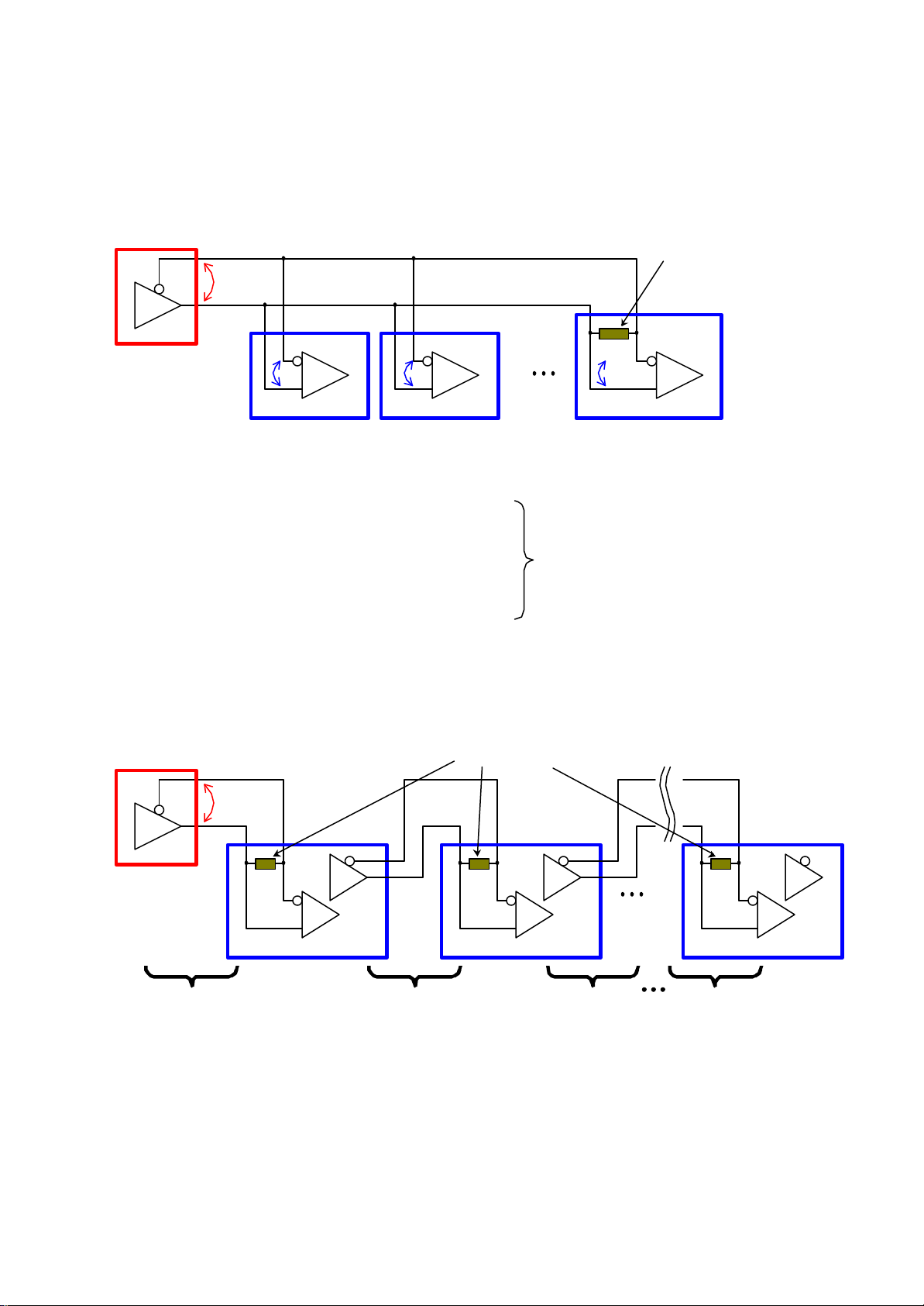
(5-2) How many slaves can be connected?
20
© 2002 Hitachi America, Ltd.
There are two ways of connecting slave SJ300 to one master SJ300.
(5-2-1) Parallel connection
Maximum 10 slaves can be connected to a master based on RS422B EIAJ US. Actual capability is 32 units.
In this case, every slave follows the master with a minimum delay.
Receiver (Slave)
R
L
Termination resistor RT (Internal)
Make it ON only at the furthest place.
150 Ω
Driver
(Master)
R
1 2 32
R
i1
i2
Fig 13-1. Parallel connection of Master-Slave control
s RS422 standard
Load impedance of the driver R
Input impedance of the receiver R
> 100
L
> 4 k
in
Ω
Ω
s Actual spec of SJ-FB
Load impedance of the driver R
Input impedance of the receiver R
> 100
L
= 12 k
in
Ω
Ω
(5-2-2) Series connection
Any numbers of slaves can be connected to a master theoretically.
Delay in response will be bigger at far end.
Termination resistor RT (Internal)
Receiver (Slave)
R
L
Make it ON for every unit
R
i32
In case of 32 slaves with SJ300;
RL = (12 k
= 107 Ω > 100
∴
Capability is 32 units
Ω
/ 32) // R
T
Ω
Driver
(Master)
Delay δ1 Delay δ2 Delay δ3 Delay δn
Total delay
= δ1
Fig 13-2. Series connection of Master-Slave control
1
Total delay
= δ1+δ2
2 n
Total delay
= δ1+δ2+δ3
Total delay
= Σδn
Page 21

(5-3) Explanation of each P parameter
SAP
SAN
SBP
SBN
Detected
SAP
SAN
SBP
SBN
Detected
21
© 2002 Hitachi America, Ltd.
[P001], [P002]
What to do in case of an option error
“00” : Make inverter trip when an option error.
“01” : Make inverter ignore the error.
[P001] is for option slot 1, and [P002] is for option slot 2.
[P010]
Function display selection related to SJ-FB under user parameter [U***] mode
“00” : Parameters related to SJ-FB do not appear on the panel.
“01” : Parameters related to SJ-FB appear on the panel.
This is nothing to do with the actual performance of the motor control. It is only a display issue.
[P011]
Pulse numbers of the encoder (ppr)
Suitable number should be set depending on the encoder to be used.
[P012]
SJ-FB control mode under V2 control mode
“00” : ASR (Speed control) mode
“01” : APR (Position control) mode
[P013]
Pulse train mode of the encoder
“00” : 90° of phase difference pulse train input
pulse numbers
Forward Reverse
“01” : FW/RV pulse and pulse train
Pulse train input
FW/RV signal
pulse numbers
Forward Reverse
Page 22
“02” : FW pulse train and RV pulse train
FW pulse train
RV pulse train
Detected
SAN
SBN
Zero servo output
PWM output
POK output
ON
22
© 2002 Hitachi America, Ltd.
SAP
SBP
pulse numbers
Forward Reverse
[P014]
Stop position during orientation
Input value is 4 time of the requested stop position (pulse numbers).
<Example>
If you want to stop the motor at 15 pulses after Z pulse is given;
[P014] = 15 * 4 = 60
[P015]
Orientation speed
Low frequency is recommended to be set (1~few Hz for example), so to get stable performance of stopping.
[P016]
Orientation direction
Set the direction during orientation.
[P017]
Completion range of positioning
SJ300 keep performing positioning until the actual stop position is inside this range.
[P018]
Delay time between Completion of positioning and output of the completion signal (POK)
s This is nothing to do with the actual
motor performance, but just a delay
time of POK output signal issue.
[P018]
[P019]
[P020]
[P021]
Fig 14. Timing chart of POK output
Position of an electronic gear
Numerator of the electronic gear
Denominator of the electronic gear
Refer to section (4-2) and
(5-1) for an information.
Page 23

[P022]
Internally calculated
Detected value from thermistor
Internally calculated
Detected value from thermistor
23
© 2002 Hitachi America, Ltd.
Feed forward gain for APR control mode
[P023]
Position loop gain for APR control mode
[P025]
Secondary resistance compensation
Refer to section (4-2) for
an information.
“00” : No compensation
“01” : With compensation
• Connect a motor thermistor between TH and CM1
terminal of the control card.
‚ Set [b098] to a suitable value
s “00” : Thermistor input invalid
s “01” : PTC type
s “02“ : NTC type
ƒ Set the resistance value [Ω] you want to make it trip.
„ Set gain adjustment by [C085]
Fig 15. Example of thermistor characteristics
resistance
20kΩ
50Ω
NTC type
resistance
Small [C085]
Big [C085]
(= Pulse count numbers in MCU)
PTC type
20kΩ
50Ω
[C085] = 0[C085] = 0
Small [C085]
(= Pulse count numbers in MCU)
Big [C085]
[P026]
Over speed trip level (%) setting
Inverter trips with over speed (E 61 or E 71) when a deviation between actual speed and target speed
exceeds the level of (Maximum frequency set) x [P026].
This can happen by an overshoot caused by incorrect settings of J ([H024]/[H034]) and/or K([H005]) value.
[P027]
Over deviation detection level (Hz) setting
Inverter gives out warning (DSE output) from an intelligent input terminal when the speed deviation exceeds
this level. The calculation is based on a deviation ε in Fig 7 and Fig 8.
Page 24

• Zero speed detection : ZS (21)
24
© 2002 Hitachi America, Ltd.
SJ300 gives out this signal when;
s Actual rotation of the motor becomes less than a set value of [C063] under V2 mode .
s PWM output frequency becomes less than a set value of [C063] under other than V2 mode.
‚ Speed deviation excessive : DSE (22)
DSE signal turns ON when an actual motor speed exceeds the set value of [P027] under V2 mode.
ƒ Positioning completion : POK (23)
POK signal turns ON when the motor stop position comes to a set range of [P017] during positioning.
Once it goes out of this range the signal turns OFF and perform positioning again.
Page 25

Appendix A Calculation of total inertia (reflected to the motor shaft)
Pulley 1
Pulley 2
Motor
Gear box
Motor
Brake
Material
Mechanics
V
[m/min]
25
© 2002 Hitachi America, Ltd.
(A-1) Ventilation Fan
s Inertia of a motor = JM[kgm2]
s Inertia of a fan = JL[kgm2] : Contact a fan manufacturer for the JL value.
Total inertia ΣJ = JM + J
L
(Note) If there is a pulley inbetween them, calculation will be as follows.
Ventilation fan
Inertia JL [kgm2]
Rotation = N1 [rpm]
Inertia JM [kgm2]
Motor J
Pulley 1
Pulley 2 J
Rotation = N1 [rpm]
Inertia J1 [kgm2]
Rotation = N2 [rpm]
Inertia J2 [kgm2]
Fan J
Total - -
(A-2) Truck
Truck : W2 [kg]
s Maximum speed = V
s Maximum motor rotation = N
max
max
[m/min]
[rpm]
Inertia Rotation Converted Inertia
M
J
1
2
L
JB [kgm2]
N
1
N
1
N
2
N
2
Ÿ W3 [kg] : Possible max. weight
J
M
J
1
2
N
2
J
⋅
2
N
1
2
N
2
J
⋅
L
N
1
2
N
2
JJJ
⋅++
2M1
N
J
L
1
2
N
2
⋅+
N
1
s Inertia of a gear box = JG[kgm2] (*)
s Inertia of mechanics = Jm[kgm2] (*)
s Inertia of a motor = JM[kgm2] (*)
s Inertia of the load = JL[kgm2]
(*) Contact each manufacturer for each
J [kgm2] value.
Total inertia ΣJ = JG + Jm + JM + J
2
VW
⋅
Ÿ [kgm2]
J
=
L
max1
2
π
2
N4
⋅⋅
max
L
W1 = W2 + W3 [kg] : Total weight
Refer to Appendix B for calculation of load inertia.
JG [kgm2]
Jm [kgm2]
M B
JM [kgm2]
N
[rpm]
max
max
: Max. speed
Page 26

(A-3) Conveyor
Geared motor
26
© 2002 Hitachi America, Ltd.
W2 [kg]
V [m/min]
W3 [kg]
D1
W4 [kg]
W1 [kg]
D2
Nm [rpm]
Na [rpm]
Ÿ J
[kgm2] : gear portion
g
s Material
Ja = (W1 × V2)/(4π × N
2
)
a
s Belt conveyor
Jb = (W2 × V2)/(4π × N
2
)
a
s Drum for the belt conveyor (2 pcs)
Jc = (1/8) × (W3 × D12) × 2
s Sprocket
Jd = (1/8) × (W4 × D22)
Total inertia converted to a motor shaft ΣJm ;
Σ
Jm = (Ja+Jb+Jc+Jd) × (Na/Nm) + Jg
Jg ; Inertia for the gear portion
Page 27

Appendix B Calculation of load inertia
27
© 2002 Hitachi America, Ltd.
(B-1) A column
J = (1/8) ž W ž D2 [kgžm2]
W [kg] : Weight
D [m] : Diameter
(B-2) A cylinder
J = (1/8) ž W ž (D2 + d2) [kgžm2]
W [kg] : Weight
D [m] : Outer diameter
d [m] : Inner diameter
(B-3) A rectangular solid
J = (1/12) ž W ž (a2 + b2) [kgžm2]
W [kg] : Weight
a [m] : Length
b [m] : Length
D
W
d
D
W
a
W
b
(B-4) A Cone
J = (3/40) ž W ž D2 [kgžm2]
W [kg] : Weight
D [m] : Diameter
D
(B-5) Wind up (vertical linear motion)
J = (1/4) ž W ž D2 [kgžm2]
W [kg] : Weight of the material
D [m] : Diameter of a drum
(B-6) Horizontal linear motion
J = ( W ž D2 ) / ( 4
W [kg] : Weight of the material
V [m/min] : Speed of the material
N [rpm] : Rotation of the converted shaft
π2 ž N2 ) [kgžm2]
W
D
Drum
Material
W
V
N
Motor
W
Refer also to appendix (A-3) for detailed explanation.
Refer to Hitachi Inverter Technical Guide Book for further detailed information of inertia.
 Loading...