

Page 1

Application Note:
A
Sizing Three-Phase
Inverters for Single-Phase
Power Applications
Please refer also to the
Inverter Instruction Manual
AN032404-1
Rev.
Hitachi America, Ltd.
© 2007 Hitachi America, Ltd.
Page 2
Sizing Three-Phase Inverters for Use with a
)
)
3
(W)
Single-Phase Supply
Although Hitachi does not offer inverters above 3 hp specifically sized and rated for
single-phase operation, single-phase power can be safely used with larger 3-phase
rated inverters, provided that care is taken to properly upsize and apply the inverter.
As background, for a given power (kW/hp) and voltage, the ratio of current for a single-
phase circuit will be
input rectifier will see 1.732 times the current of the output devices. When powered by
three-phase, these currents are nearly the same. This higher current would destroy the
input of the drive if an oversized inverter were not used. Furthermore, full-wave rectified
single-phase power has a much higher harmonic content than full-wave rectified threephase power. This would introduce large ripple into the DC bus of the inverter,
potentially causing other malfunctions. Larger size inverters have larger bus capacitors,
thus more inherent filtering. So upsizing the drive ameliorates the ripple problem as well.
The rule of thumb Hitachi recommends is to start with the 3-phase motor’s nameplate full
load amperage (FLA) rating and double it. Then select an inverter with this doubled
continuous current rating. This will give adequate margin in the input rectifier bridge and
bus capacitors to provide reliable performance. NOTE: Fusing or Circuit Breakers should
be sized to match the INVERTER input current rating, NOT the motor current rating!
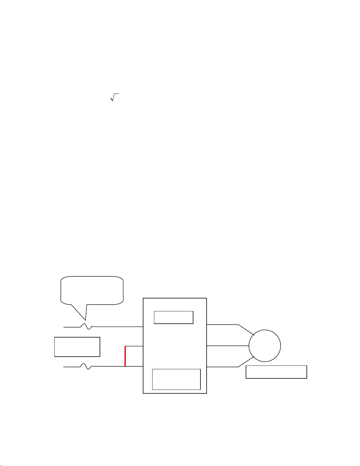
As shown in the figure below, single-phase power should be connected to the L1 (R) and
L3 (T) terminals, and optionally, a jumper should be placed between terminals L2(S) and
L3(T). This jumper prevents the inverter from detecting a loss-of-phase should that
function be active. Otherwise, the L2 (S) terminal should remain unconnected.
Beyond the inverter considerations, be sure to size components upstream of the inverter
to match the INVERTER’S current ratings, NOT the motor’s. This would include, but not
be limited to wiring, fusing, circuit breakers, contactors, etc.
3 (1.732) times that of a three-phase circuit. This means that the
Fuses/Ckt Bkrs sized
to INVERTER input
current rating
Single-Phase
Input Power
L1 (R)
L2 (S)
Optional
Jumper
L3 (T)
INVERTER
Nameplate:
≥ (nx2) Amps
T1(U
T2(V
T
Hitachi America, Ltd.
© 2007 Hitachi America, Ltd.
MOTOR
Nameplate: n Amps
 Loading...