

Page 1
Hitachi AMS 2000 Family TrueCopy Extended
Distance User Guide
F
AST
F
IND
L
INKS
Document organization
Release notes and readme
Getting help
Table of Contents
MK-97DF8054-23
Page 2

© 2008-2015 Hitachi, Ltd. All rights reserved.
No part of this publication may be reproduced or transmitted in any form or by any means, electronic or
mechanical, including photocopying and recording, or stored in a database or retrieval system for any
purpose without the express written permission of Hitachi, Ltd. and Hitachi Data Systems Corporation
(hereinafter referred to as “Hitachi”).
Hitachi, Ltd. and Hitachi Data Systems reserve the right to make changes to this document at any time
without notice and assume no responsibility for its use. Hitachi, Ltd. and Hitachi Data Systems products and
services can only be ordered under the terms and conditions of Hitachi Data Systems' applicable agreements.
All of the features described in this document may not be currently available. Refer to the most recent
product announcement or contact your local Hitachi Data Systems sales office for information on feature and
product availability.
Notice: Hitachi Data Systems products and services can be ordered only under the terms and conditions of
Hitachi Data Systems’ applicable agreements. The use of Hitachi Data Systems products is governed by the
terms of your agreements with Hitachi Data Systems.
Hitachi is a registered trademark of Hitachi, Ltd. in the United States and other countries. Hitachi Data
Systems is a registered trademark and service mark of Hitachi in the United States and other countries.
All other trademarks, service marks, and company names are properties of their respective owners.
Export authorization is required for the AMS 2000 Data At Rest Encryption
• Import/Use regulations may restrict export of the AMS2000 SED to certain countries
• China – AMS2000 is eligible for import but the License Key and SED may not be sent to China
• France – Import pending completion of registration formalities
• Hong Kong – Import pending completion of registration formalities
• Israel – Import pending completion of registration formalities
• Russia – Import pending completion of notification formalities
• Distribution Centers – IDC, EDC and ADC cleared for exports
ii
Hitachi AMS 2000 Family TrueCopy Extended Distance User Guide
Page 3

Table of Contents
Preface . . . . . . . . . . . . . . . . . . . . . . . . . . . . . . . . . . . . . . . . . . . . . . . . ix
Intended audience . . . . . . . . . . . . . . . . . . . . . . . . . . . . . . . . . . . . . . . . . . . .x
Product version . . . . . . . . . . . . . . . . . . . . . . . . . . . . . . . . . . . . . . . . . . . . . .x
Release notes and readme . . . . . . . . . . . . . . . . . . . . . . . . . . . . . . . . . . . . . .x
Product Abbreviations. . . . . . . . . . . . . . . . . . . . . . . . . . . . . . . . . . . . . . . . . .x
Document revision level . . . . . . . . . . . . . . . . . . . . . . . . . . . . . . . . . . . . . . . xi
Changes in this release . . . . . . . . . . . . . . . . . . . . . . . . . . . . . . . . . . . . . . . . xii
Document organization . . . . . . . . . . . . . . . . . . . . . . . . . . . . . . . . . . . . . . . . xii
Document conventions . . . . . . . . . . . . . . . . . . . . . . . . . . . . . . . . . . . . . . . .xiv
Convention for storage capacity values. . . . . . . . . . . . . . . . . . . . . . . . . . . . . xv
Related documents. . . . . . . . . . . . . . . . . . . . . . . . . . . . . . . . . . . . . . . . . . . xv
Getting help. . . . . . . . . . . . . . . . . . . . . . . . . . . . . . . . . . . . . . . . . . . . . . . . xx
Comments . . . . . . . . . . . . . . . . . . . . . . . . . . . . . . . . . . . . . . . . . . . . . . . xx
1 Overview . . . . . . . . . . . . . . . . . . . . . . . . . . . . . . . . . . . . . . . . . . . . . 1-1
How TCE works . . . . . . . . . . . . . . . . . . . . . . . . . . . . . . . . . . . . . . . . . . . . 1-2
Typical environment . . . . . . . . . . . . . . . . . . . . . . . . . . . . . . . . . . . . . . . . . 1-2
Volume pairs. . . . . . . . . . . . . . . . . . . . . . . . . . . . . . . . . . . . . . . . . . . . . 1-3
Data pools . . . . . . . . . . . . . . . . . . . . . . . . . . . . . . . . . . . . . . . . . . . . . . 1-4
Guaranteed write order and the update cycle. . . . . . . . . . . . . . . . . . . . . . 1-4
Extended update cycles . . . . . . . . . . . . . . . . . . . . . . . . . . . . . . . . . . . 1-5
Consistency groups . . . . . . . . . . . . . . . . . . . . . . . . . . . . . . . . . . . . . . . . 1-6
Differential Management LUs (DMLU) . . . . . . . . . . . . . . . . . . . . . . . . . . . 1-7
TCE interfaces . . . . . . . . . . . . . . . . . . . . . . . . . . . . . . . . . . . . . . . . . . . . . 1-7
2 Plan and design — sizing data pools and bandwidth . . . . . . . . . 2-1
Plan and design workflow . . . . . . . . . . . . . . . . . . . . . . . . . . . . . . . . . . . . . 2-2
Assessing business needs — RPO and the update cycle . . . . . . . . . . . . . . . . 2-2
Measuring write-workload . . . . . . . . . . . . . . . . . . . . . . . . . . . . . . . . . . . . . 2-3
Collecting write-workload data . . . . . . . . . . . . . . . . . . . . . . . . . . . . . . 2-3
Calculating data pool size . . . . . . . . . . . . . . . . . . . . . . . . . . . . . . . . . . . . . 2-4
Contents iii
Hitachi AMS 2000 Family TrueCopy Extended Distance User Guide
Page 4

Data pool key points . . . . . . . . . . . . . . . . . . . . . . . . . . . . . . . . . . . . . .2-7
Determining bandwidth . . . . . . . . . . . . . . . . . . . . . . . . . . . . . . . . . . . . . . .2-8
3 Plan and design — remote path . . . . . . . . . . . . . . . . . . . . . . . . . . .3-1
Remote path requirements. . . . . . . . . . . . . . . . . . . . . . . . . . . . . . . . . . . . .3-2
Management LAN requirements . . . . . . . . . . . . . . . . . . . . . . . . . . . . . . . .3-3
Remote data path requirements. . . . . . . . . . . . . . . . . . . . . . . . . . . . . . . .3-3
WAN optimization controller (WOC) requirements . . . . . . . . . . . . . . . . . . .3-4
Remote path configurations . . . . . . . . . . . . . . . . . . . . . . . . . . . . . . . . . . . .3-5
Fibre channel . . . . . . . . . . . . . . . . . . . . . . . . . . . . . . . . . . . . . . . . . . . . .3-5
Direct connection . . . . . . . . . . . . . . . . . . . . . . . . . . . . . . . . . . . . . . . .3-6
Single FC switch, network connection . . . . . . . . . . . . . . . . . . . . . . . . . .3-7
Double FC switch, network connection . . . . . . . . . . . . . . . . . . . . . . . . .3-8
Fibre channel extender connection . . . . . . . . . . . . . . . . . . . . . . . . . . . .3-9
Port transfer rate for Fibre channel. . . . . . . . . . . . . . . . . . . . . . . . . . .3-10
iSCSI. . . . . . . . . . . . . . . . . . . . . . . . . . . . . . . . . . . . . . . . . . . . . . . . . .3-11
Direct connection . . . . . . . . . . . . . . . . . . . . . . . . . . . . . . . . . . . . . . .3-11
Single LAN switch, WAN connection . . . . . . . . . . . . . . . . . . . . . . . . . .3-12
Multiple LAN switch, WAN connection. . . . . . . . . . . . . . . . . . . . . . . . .3-13
Single LAN switch, WOC, WAN connection. . . . . . . . . . . . . . . . . . . . . .3-14
Multiple LAN switch, WOC, WAN connection . . . . . . . . . . . . . . . . . . . .3-15
Multiple array, LAN switch, WOC connection with single WAN . . . . . . . .3-16
Multiple array, LAN switch, WOC connection with two WANs. . . . . . . . .3-17
Supported connections between various types of arrays . . . . . . . . . . . . . . .3-18
Notes when Connecting Hitachi AMS2000 Series to other arrays . . . . . . . .3-18
Using the remote path — best practices. . . . . . . . . . . . . . . . . . . . . . . . . . .3-20
4 Plan and design—arrays, volumes and operating systems. . . . .4-1
Planning workflow . . . . . . . . . . . . . . . . . . . . . . . . . . . . . . . . . . . . . . . . . . .4-2
Planning arrays—moving data from earlier AMS models. . . . . . . . . . . . . . . . .4-2
Planning logical units for TCE volumes. . . . . . . . . . . . . . . . . . . . . . . . . . . . .4-3
Volume pair and data pool recommendations . . . . . . . . . . . . . . . . . . . . . .4-3
Operating system recommendations and restrictions. . . . . . . . . . . . . . . . . . .4-4
Host time-out. . . . . . . . . . . . . . . . . . . . . . . . . . . . . . . . . . . . . . . . . . . . .4-4
P-VOL, S-VOL recognition by same host on VxVM, AIX®, LVM . . . . . . . . . .4-4
HP server. . . . . . . . . . . . . . . . . . . . . . . . . . . . . . . . . . . . . . . . . . . . . . . .4-4
Windows Server 2000 . . . . . . . . . . . . . . . . . . . . . . . . . . . . . . . . . . . . . . .4-7
Windows Server 2003/2008. . . . . . . . . . . . . . . . . . . . . . . . . . . . . . . . . . .4-7
Identifying P-VOL and S-VOL LUs on Windows. . . . . . . . . . . . . . . . . . . .4-8
Windows 2000 or Windows Server and TCE Configuration . . . . . . . . . . .4-9
Dynamic Disk in Windows 2000/Windows Server . . . . . . . . . . . . . . . . .4-10
VMWare and TCE Configuration . . . . . . . . . . . . . . . . . . . . . . . . . . . . .4-10
Concurrent Use of Dynamic Provisioning. . . . . . . . . . . . . . . . . . . . . . .4-11
iv Contents
Hitachi AMS 2000 Family TrueCopy Extended Distance User Guide
Page 5

User Data Area of Cache Memory . . . . . . . . . . . . . . . . . . . . . . . . . . . .4-16
Formatting the DMLU in the Event of a Drive Failure. . . . . . . . . . . . . . . . .4-22
Maximum supported capacity . . . . . . . . . . . . . . . . . . . . . . . . . . . . . . . . . .4-23
TCE and SnapShot capacity . . . . . . . . . . . . . . . . . . . . . . . . . . . . . . . . . .4-24
TCE, SnapShot, ShadowImage concurrent capacity . . . . . . . . . . . . . . . . .4-26
. . . . . . . . . . . . . . .Maximum Supported Capacity of P-VOL and Data Pool4-28
No SnapShot-TCE cascade configuration . . . . . . . . . . . . . . . . . . . . . . .4-29
SnapShot-TCE cascade configuration. . . . . . . . . . . . . . . . . . . . . . . . . .4-30
Cache limitations on data and data pool volumes . . . . . . . . . . . . . . . . . . .4-31
Cautions for Reconfiguring the Cache Memory. . . . . . . . . . . . . . . . . . . . .4-32
5 Requirements and specifications . . . . . . . . . . . . . . . . . . . . . . . . . .5-1
TCE system requirements . . . . . . . . . . . . . . . . . . . . . . . . . . . . . . . . . . . . . 5-2
Displaying the hardware revision number . . . . . . . . . . . . . . . . . . . . . . . . 5-3
TCE system specifications. . . . . . . . . . . . . . . . . . . . . . . . . . . . . . . . . . . . . 5-3
6 Installation and setup. . . . . . . . . . . . . . . . . . . . . . . . . . . . . . . . . . . .6-1
Installation procedures. . . . . . . . . . . . . . . . . . . . . . . . . . . . . . . . . . . . . . . 6-2
Installing TCE . . . . . . . . . . . . . . . . . . . . . . . . . . . . . . . . . . . . . . . . . . . . 6-3
Enabling or disabling TCE. . . . . . . . . . . . . . . . . . . . . . . . . . . . . . . . . . . . 6-6
Un-installing TCE. . . . . . . . . . . . . . . . . . . . . . . . . . . . . . . . . . . . . . . . . . 6-8
Setup procedures. . . . . . . . . . . . . . . . . . . . . . . . . . . . . . . . . . . . . . . . . . .6-11
Setting up DMLUs . . . . . . . . . . . . . . . . . . . . . . . . . . . . . . . . . . . . . . . . .6-11
Setting up data pools. . . . . . . . . . . . . . . . . . . . . . . . . . . . . . . . . . . . . . .6-12
Adding or changing the remote port CHAP secret. . . . . . . . . . . . . . . . . . .6-14
Setting up the remote path . . . . . . . . . . . . . . . . . . . . . . . . . . . . . . . . . .6-15
7 Pair operations . . . . . . . . . . . . . . . . . . . . . . . . . . . . . . . . . . . . . . . . .7-1
Operations work flow . . . . . . . . . . . . . . . . . . . . . . . . . . . . . . . . . . . . . . . . 7-2
TCE operations . . . . . . . . . . . . . . . . . . . . . . . . . . . . . . . . . . . . . . . . . . . . 7-3
Checking pair status. . . . . . . . . . . . . . . . . . . . . . . . . . . . . . . . . . . . . . . . . 7-3
Creating the initial copy . . . . . . . . . . . . . . . . . . . . . . . . . . . . . . . . . . . . . . 7-3
Prerequisites and best practices for pair creation . . . . . . . . . . . . . . . . . . . 7-4
TCE setup wizard . . . . . . . . . . . . . . . . . . . . . . . . . . . . . . . . . . . . . . . . . 7-4
Create pair procedure . . . . . . . . . . . . . . . . . . . . . . . . . . . . . . . . . . . . . . 7-5
Splitting a pair. . . . . . . . . . . . . . . . . . . . . . . . . . . . . . . . . . . . . . . . . . . . . 7-6
Resynchronizing a pair . . . . . . . . . . . . . . . . . . . . . . . . . . . . . . . . . . . . . . . 7-7
Swapping pairs . . . . . . . . . . . . . . . . . . . . . . . . . . . . . . . . . . . . . . . . . . . . 7-9
8 Example scenarios and procedures . . . . . . . . . . . . . . . . . . . . . . . .8-1
CLI scripting procedure for S-VOL backup. . . . . . . . . . . . . . . . . . . . . . . . . . 8-2
Scripted TCE, SnapShot procedure . . . . . . . . . . . . . . . . . . . . . . . . . . . . . 8-4
Procedure for swapping I/O to S-VOL when maintaining local array . . . . . . . 8-9
Contents v
Hitachi AMS 2000 Family TrueCopy Extended Distance User Guide
Page 6

Procedure for moving data to a remote array. . . . . . . . . . . . . . . . . . . . . . .8-10
Example procedure for moving data . . . . . . . . . . . . . . . . . . . . . . . . . . . .8-11
Process for disaster recovery . . . . . . . . . . . . . . . . . . . . . . . . . . . . . . . . . .8-11
Takeover processing. . . . . . . . . . . . . . . . . . . . . . . . . . . . . . . . . . . . . . .8-11
Swapping P-VOL and S-VOL. . . . . . . . . . . . . . . . . . . . . . . . . . . . . . . . . .8-12
Failback to the local array . . . . . . . . . . . . . . . . . . . . . . . . . . . . . . . . . . .8-12
9 Monitoring and maintenance. . . . . . . . . . . . . . . . . . . . . . . . . . . . . .9-1
Monitoring pair status . . . . . . . . . . . . . . . . . . . . . . . . . . . . . . . . . . . . . . . .9-2
Monitoring data pool capacity . . . . . . . . . . . . . . . . . . . . . . . . . . . . . . . . . . .9-5
Monitoring data pool usage . . . . . . . . . . . . . . . . . . . . . . . . . . . . . . . . . . .9-5
Expanding data pool capacity. . . . . . . . . . . . . . . . . . . . . . . . . . . . . . . . . .9-6
Changing data pool threshold value . . . . . . . . . . . . . . . . . . . . . . . . . . . . .9-6
Monitoring the remote path . . . . . . . . . . . . . . . . . . . . . . . . . . . . . . . . . . . .9-7
Changing remote path bandwidth. . . . . . . . . . . . . . . . . . . . . . . . . . . . . . .9-7
Monitoring cycle time. . . . . . . . . . . . . . . . . . . . . . . . . . . . . . . . . . . . . . . . .9-7
Changing cycle time . . . . . . . . . . . . . . . . . . . . . . . . . . . . . . . . . . . . . . . .9-8
Changing copy pace. . . . . . . . . . . . . . . . . . . . . . . . . . . . . . . . . . . . . . . . . .9-8
Checking RPO — Monitoring P-VOL/S-VOL time difference. . . . . . . . . . . . . . .9-9
Routine maintenance. . . . . . . . . . . . . . . . . . . . . . . . . . . . . . . . . . . . . . . . .9-9
Deleting a volume pair . . . . . . . . . . . . . . . . . . . . . . . . . . . . . . . . . . . . . .9-9
Deleting data pools. . . . . . . . . . . . . . . . . . . . . . . . . . . . . . . . . . . . . . . .9-10
Deleting a DMLU. . . . . . . . . . . . . . . . . . . . . . . . . . . . . . . . . . . . . . . . . .9-10
Deleting the remote path. . . . . . . . . . . . . . . . . . . . . . . . . . . . . . . . . . . .9-11
TCE tasks before a planned remote array shutdown. . . . . . . . . . . . . . . . .9-11
. . . . . . . . . . . . . . . . . . . . . . . . . . . . . . . . . . . . . . . . . . . . . . . . . . . . . .9-11
10 Troubleshooting . . . . . . . . . . . . . . . . . . . . . . . . . . . . . . . . . . . . . . .10-1
Troubleshooting overview. . . . . . . . . . . . . . . . . . . . . . . . . . . . . . . . . . . . .10-2
Correcting data pool shortage. . . . . . . . . . . . . . . . . . . . . . . . . . . . . . . . . .10-2
Correcting array problems . . . . . . . . . . . . . . . . . . . . . . . . . . . . . . . . . . . .10-3
Delays in settling of S-VOL Data. . . . . . . . . . . . . . . . . . . . . . . . . . . . .10-4
Correcting resynchronization errors . . . . . . . . . . . . . . . . . . . . . . . . . . . . . .10-4
Using the event log . . . . . . . . . . . . . . . . . . . . . . . . . . . . . . . . . . . . . . . . .10-7
Recovering a TrueCopy path. . . . . . . . . . . . . . . . . . . . . . . . . . . . . . . . . . .10-8
Miscellaneous troubleshooting. . . . . . . . . . . . . . . . . . . . . . . . . . . . . . . . .10-10
A Operations using CLI. . . . . . . . . . . . . . . . . . . . . . . . . . . . . . . . . . . A-1
Installation and setup . . . . . . . . . . . . . . . . . . . . . . . . . . . . . . . . . . . . . . . .A-2
Installing . . . . . . . . . . . . . . . . . . . . . . . . . . . . . . . . . . . . . . . . . . . . . . . .A-3
Enabling and disabling . . . . . . . . . . . . . . . . . . . . . . . . . . . . . . . . . . . . . .A-5
Un-installing. . . . . . . . . . . . . . . . . . . . . . . . . . . . . . . . . . . . . . . . . . . . . .A-8
Setting the Differential Management Logical Unit. . . . . . . . . . . . . . . . . . .A-10
vi Contents
Hitachi AMS 2000 Family TrueCopy Extended Distance User Guide
Page 7

Release a DMLU . . . . . . . . . . . . . . . . . . . . . . . . . . . . . . . . . . . . . . . . . A-10
Setting the data pool. . . . . . . . . . . . . . . . . . . . . . . . . . . . . . . . . . . . . . A-10
Setting the LU ownership. . . . . . . . . . . . . . . . . . . . . . . . . . . . . . . . . . . A-12
Setting the cycle time . . . . . . . . . . . . . . . . . . . . . . . . . . . . . . . . . . . . . A-13
Setting mapping information . . . . . . . . . . . . . . . . . . . . . . . . . . . . . . . . A-13
Setting the remote port CHAP secret. . . . . . . . . . . . . . . . . . . . . . . . . . . A-14
Setting the remote path. . . . . . . . . . . . . . . . . . . . . . . . . . . . . . . . . . . . A-15
Deleting the remote path. . . . . . . . . . . . . . . . . . . . . . . . . . . . . . . . . . . A-17
Pair operations. . . . . . . . . . . . . . . . . . . . . . . . . . . . . . . . . . . . . . . . . . . . A-20
Displaying status for all pairs . . . . . . . . . . . . . . . . . . . . . . . . . . . . . . . . A-20
Displaying detail for a specific pair . . . . . . . . . . . . . . . . . . . . . . . . . . . . A-20
Creating a pair . . . . . . . . . . . . . . . . . . . . . . . . . . . . . . . . . . . . . . . . . . A-21
Splitting a pair . . . . . . . . . . . . . . . . . . . . . . . . . . . . . . . . . . . . . . . . . . A-21
Resynchronizing a pair. . . . . . . . . . . . . . . . . . . . . . . . . . . . . . . . . . . . . A-22
Swapping a pair . . . . . . . . . . . . . . . . . . . . . . . . . . . . . . . . . . . . . . . . . A-22
Deleting a pair . . . . . . . . . . . . . . . . . . . . . . . . . . . . . . . . . . . . . . . . . . A-22
Changing pair information . . . . . . . . . . . . . . . . . . . . . . . . . . . . . . . . . . A-23
Monitoring pair status . . . . . . . . . . . . . . . . . . . . . . . . . . . . . . . . . . . . . A-23
Confirming Consistency Group (CTG) status. . . . . . . . . . . . . . . . . . . . . . A-24
Procedures for failure recovery . . . . . . . . . . . . . . . . . . . . . . . . . . . . . . . . A-25
Displaying the event log. . . . . . . . . . . . . . . . . . . . . . . . . . . . . . . . . . . . A-25
Reconstructing the remote path . . . . . . . . . . . . . . . . . . . . . . . . . . . . . . A-25
Sample script. . . . . . . . . . . . . . . . . . . . . . . . . . . . . . . . . . . . . . . . . . . . . A-26
B Operations using CCI. . . . . . . . . . . . . . . . . . . . . . . . . . . . . . . . . . . B-1
Setup . . . . . . . . . . . . . . . . . . . . . . . . . . . . . . . . . . . . . . . . . . . . . . . . . . . B-2
Setting the command device . . . . . . . . . . . . . . . . . . . . . . . . . . . . . . . . . B-2
Setting LU mapping. . . . . . . . . . . . . . . . . . . . . . . . . . . . . . . . . . . . . . . . B-3
Defining the configuration definition file . . . . . . . . . . . . . . . . . . . . . . . . . B-4
Setting the environment variable . . . . . . . . . . . . . . . . . . . . . . . . . . . . . . B-6
Pair operations. . . . . . . . . . . . . . . . . . . . . . . . . . . . . . . . . . . . . . . . . . . . . B-7
Checking pair status . . . . . . . . . . . . . . . . . . . . . . . . . . . . . . . . . . . . . . . B-7
Creating a pair (paircreate) . . . . . . . . . . . . . . . . . . . . . . . . . . . . . . . . . . B-8
Splitting a pair (pairsplit) . . . . . . . . . . . . . . . . . . . . . . . . . . . . . . . . . . . . B-8
Resynchronizing a pair (pairresync). . . . . . . . . . . . . . . . . . . . . . . . . . . . . B-9
Suspending pairs (pairsplit -R) . . . . . . . . . . . . . . . . . . . . . . . . . . . . . . . . B-9
Releasing pairs (pairsplit -S). . . . . . . . . . . . . . . . . . . . . . . . . . . . . . . . . B-10
Splitting TCE S-VOL/SnapShot V-VOL pair (pairsplit -mscas) . . . . . . . . . . B-10
Confirming data transfer when status is PAIR . . . . . . . . . . . . . . . . . . . . B-13
Pair creation/resynchronization for each CTG. . . . . . . . . . . . . . . . . . . . . B-13
Response time of pairsplit command. . . . . . . . . . . . . . . . . . . . . . . . . . . B-15
Pair, group name differences in CCI and Navigator 2. . . . . . . . . . . . . . . . . B-18
C Cascading with SnapShot. . . . . . . . . . . . . . . . . . . . . . . . . . . . . . . C-1
Contents vii
Hitachi AMS 2000 Family TrueCopy Extended Distance User Guide
Page 8

Cascade configurations . . . . . . . . . . . . . . . . . . . . . . . . . . . . . . . . . . . . . . .C-2
Replication operations supported . . . . . . . . . . . . . . . . . . . . . . . . . . . . . . . .C-2
TCE operations supported . . . . . . . . . . . . . . . . . . . . . . . . . . . . . . . . . . . .C-3
SnapShot operations supported . . . . . . . . . . . . . . . . . . . . . . . . . . . . . . . .C-4
Status combinations, Read/write supported . . . . . . . . . . . . . . . . . . . . . . . . .C-4
Guidelines and restrictions . . . . . . . . . . . . . . . . . . . . . . . . . . . . . . . . . . . . .C-6
Cascading with SnapShot on the remote side . . . . . . . . . . . . . . . . . . . . . .C-6
TCE, SnapShot behaviors compared . . . . . . . . . . . . . . . . . . . . . . . . . . . . . .C-7
D Installing TCE when Cache Partition Manager is in use . . . . . . D-1
Initializing Cache Partition when TCE and SnapShot are installed . . . . . . . . . D-2
E Wavelength Division Multiplexing (WDM) and dark fibre. . . . . . .E-1
WDM and dark fibre. . . . . . . . . . . . . . . . . . . . . . . . . . . . . . . . . . . . . . . . . .E-2
Glossary
Index
viii Contents
Hitachi AMS 2000 Family TrueCopy Extended Distance User Guide
Page 9

Preface
This document provides instructions for planning, setting up, and
operating TrueCopy Extended Distance.
This preface includes the following information:
Intended audience
Product version
Release notes and readme
Changes in this release
Changes in this release
Document organization
Document conventions
Convention for storage capacity values
Related documents
Getting help
Preface ix
Hitachi AMS 2000 Family TrueCopy Extended Distance User Guide
Page 10
Intended audience
This document is intended for system administrators, Hitachi Data Systems
representatives, and Authorized Service Providers who install, configure,
and operate Hitachi Adaptable Modular System (AMS) 2000 family storage
systems.
Product version
This document applies to Hitachi AMS 2000 Family firmware version
08D1/B or later.
Release notes and readme
Read the release notes and readme file before installing and using this
product. They may contain requirements or restrictions that are not fully
described in this document and/or updates or corrections to this document
Product Abbreviations
Product Abbreviation
ShadowImage ShadowImage In-system Replication
Snapshot Copy-on-Write Snapshot
TrueCopy Remote TrueCopy Remote Replication
TCE TrueCopy Extended Distance
TCMD TrueCopy Modular Distributed
Windows Server Windows Server 2003, Windows Server 2008,
and Windows Server 2012.
Product Full Name
x Preface
Hitachi AMS 2000 Family TrueCopy Extended Distance User Guide
Page 11
Changes in this release
•In Table 5-2 (page 5-3), added the parameter Remote Copy over iSCSI
in the WAN environment.
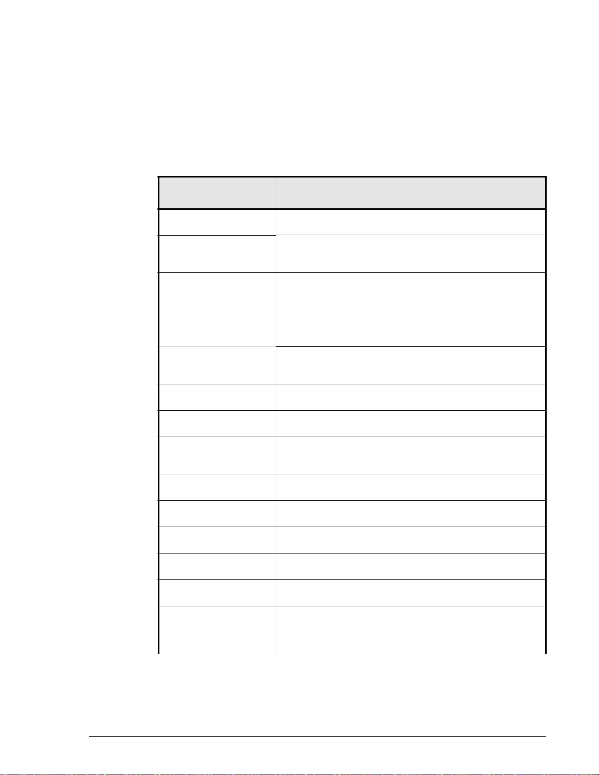
Document organization
Thumbnail descriptions of the chapters are provided in the following table.
Click the chapter title in the first column to go to that chapter. The first page
of every chapter or appendix contains links to the contents.
Chapter/Appendix
Title
Chapter 1, Overview Provides descriptions of TrueCopy Extended Distance
components and how they work together.
Chapter 2, Plan and
design — sizing data
pools and bandwidth
Chapter 3, Plan and
design — remote path
Chapter 4, Plan and
design—arrays,
volumes and operating
systems
Chapter 5,
Requirements and
specifications
Chapter 6, Installation
and setup
Chapter 7, Pair
operations
Chapter 8, Example
scenarios and
procedures
Chapter 9, Monitoring
and maintenance
Chapter 10,
Troubleshooting
Appendix A,
Operations using CLI
Appendix B,
Operations using CCI
Appendix C, Cascading
with SnapShot
Appendix D, Installing
TCE when Cache
Partition Manager is in
use
Provides instructions for measuring write-workload,
calculating data pool size and bandwidth.
Provides supported iSCSI and Fibre Channel
configurations, with information on WDM and dark fibre.
Discusses the arrays and volumes you can use for TCE.
Provides TCE system requirements and specifications.
Provides procedures for installing and setting up the TCE
system and creating the initial copy.
Provides information and procedures for TCE operations.
Provides backup, data moving, and disaster recovery
scenarios and procedures.
Provides monitoring and maintenance information.
Provides troubleshooting information.
Provides detailed Command Line Interface instructions for
configuring and using TCE.
Provides detailed Command Line Interface instructions for
configuring and using TCE.
Provides supported configurations, operations, etc. for
cascading TCE with SnapShot.
Provides required information when using Cache Partition
Manager.
Description
Preface xi
Hitachi AMS 2000 Family TrueCopy Extended Distance User Guide
Page 12
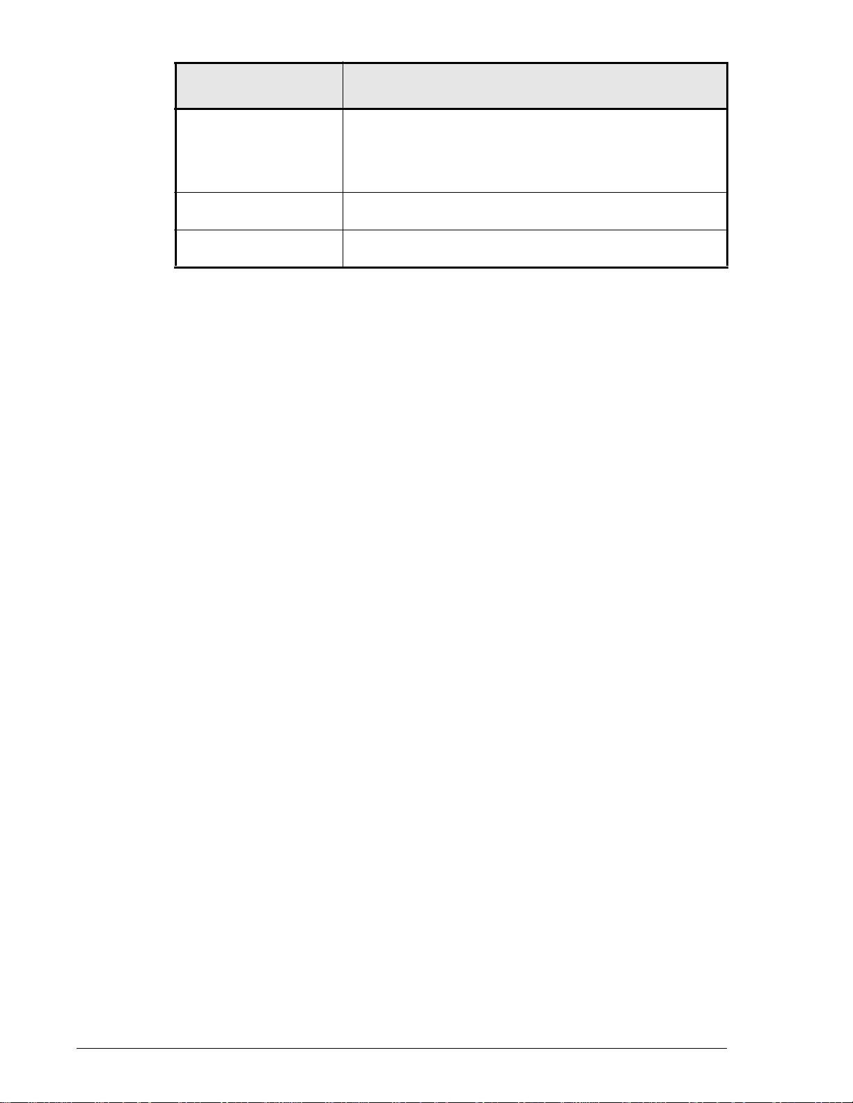
Chapter/Appendix
Title
Description
Appendix E,
Wavelength
Provides a discussion of WDM and dark fibre for channel
extender.
Division
Multiplexing (WDM)
and dark fibre
Glossary Provides definitions for terms and acronyms found in this
document.
Index Provides links and locations to specific information in this
document.
xii Preface
Hitachi AMS 2000 Family TrueCopy Extended Distance User Guide
Page 13
Document conventions
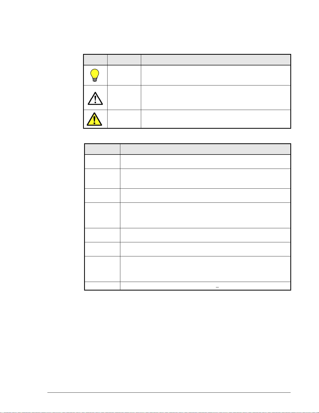
This document uses the following symbols to draw attention to important
safety and operational information.
Symbol Meaning Description
Tip Tips provide helpful information, guidelines, or suggestions for
Note Notes emphasize or supplement important points of the main
Caution Cautions indicate that failure to take a specified action could
The following typographic conventions are used in this document.
Convention Description
Bold Indicates text on a window, other than the window title, including
menus, menu options, buttons, fields, and labels. Example: Click OK.
Italic Indicates a variable, which is a placeholder for actual text provided by
the user or system. Example: copy source-file target-file
Angled brackets (< >) are also used to indicate variables.
screen/code Indicates text that is displayed on screen or entered by the user.
Example: # pairdisplay -g oradb
< > angled
brackets
Indicates a variable, which is a placeholder for actual text provided by
the user or system. Example: # pairdisplay -g <group>
performing tasks more effectively.
text.
result in damage to the software or hardware.
Italic font is also used to indicate variables.
[ ] square
brackets
{ } braces Indicates required or expected values. Example: { a | b } indicates that
| vertical bar Indicates that you have a choice between two or more options or
underline Indicates the default value. Example: [ a | b ]
Indicates optional values. Example: [ a | b ] indicates that you can
choose a, b, or nothing.
you must choose either a or b.
arguments. Examples:
[ a | b ] indicates that you can choose a, b, or nothing.
{ a | b } indicates that you must choose either a or b.
Preface xiii
Hitachi AMS 2000 Family TrueCopy Extended Distance User Guide
Page 14
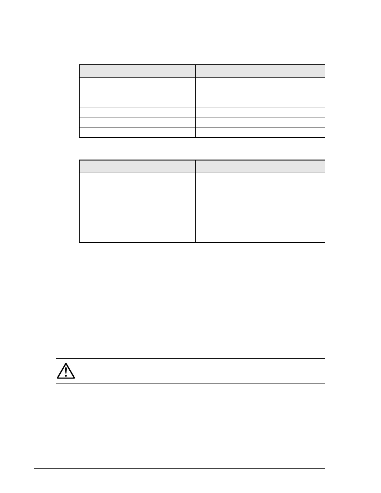
Convention for storage capacity values
Physical storage capacity values (e.g., disk drive capacity) are calculated
based on the following values:
Physical capacity unit Value
1 KB 1,000 bytes
1 MB 1,000 KB or 1,000
1 GB 1,000 MB or 1,0003 bytes
1 TB 1,000 GB or 1,0004 bytes
1 PB 1,000 TB or 1,0005 bytes
1 EB 1,000 PB or 1,000
Logical storage capacity values (e.g., logical device capacity) are calculated
based on the following values:
Logical capacity unit Value
1 block 512 bytes
1 KB 1,024 (210) bytes
1 MB 1,024 KB or 1024
1 GB 1,024 MB or 10243 bytes
1 TB 1,024 GB or 10244 bytes
1 PB 1,024 TB or 1024
1 EB 1,024 PB or 10246 bytes
2
bytes
6
bytes
2
bytes
5
bytes
Related documents
The AMS 2000 Family user documentation is available on the Hitachi Data
Systems Portal: https://portal.hds.com. Please check this site for the most
current documentation, including important updates that may have been
made after the release of the product.
This documentation set consists of the following documents.
Release notes
• Adaptable Modular Storage System Release Notes
• Storage Navigator Modular 2 Release Notes
Please read the release notes before installing and/or using this product.
They may contain requirements and/or restrictions not fully described in
this document, along with updates and/or corrections to this document.
xiv Preface
Hitachi AMS 2000 Family TrueCopy Extended Distance User Guide
Page 15

Installation and getting started
The following documents provide instructions for installing an AMS 2000
Family storage system. They include rack information, safety information,
site-preparation instructions, getting-started guides for experienced users,
and host connectivity information. The symbol
that contain initial configuration information about Hitachi AMS 2000 Family
storage systems.
identifies documents
AMS2100/2300 Getting Started Guide, MK-98DF8152
Provides quick-start instructions for getting an AMS 2100 or AMS 2300
storage system up and running as quickly as possible.
AMS2500 Getting Started Guide,
MK-97DF8032 Provides quick-start instructions for getting an AMS 2500
storage system up and running as quickly as possible
AMS 2000 Family Site Preparation Guide, MK-98DF8149
Contains site planning and pre-installation information for AMS 2000
Family storage systems, expansion units, and high-density expansion
units. This document also covers safety precautions, rack information,
and product specifications.
AMS 2000 Family Fibre Channel Host Installation Guide,
MK-08DF8189
Describes how to prepare Hitachi AMS 2000 Family Fibre Channel
storage systems for use with host servers running supported operating
systems.
AMS 2000 Family iSCSI Host Installation Guide, MK-08DF8188
Describes how to prepare Hitachi AMS 2000 Family iSCSI storage
systems for use with host servers running supported operating systems.
Storage and replication features
The following documents describe how to use Storage Navigator Modular 2
(Navigator 2) to perform storage and replication activities.
Storage Navigator 2 Advanced Settings User’s Guide, MK-97DF8039
Contains advanced information about launching and using Navigator 2
in various operating systems, IP addresses and port numbers, server
certificates and private keys, boot and restore options, outputting
configuration information to a file, and collecting diagnostic information.
Preface xv
Hitachi AMS 2000 Family TrueCopy Extended Distance User Guide
Page 16

Storage Navigator Modular 2 User’s Guide, MK-99DF8208
Describes how to use Navigator 2 to configure and manage storage on
an AMS 2000 Family storage system.
AMS 2000 Family Dynamic Provisioning Configuration Guide,
MK-09DF8201
Describes how to use virtual storage capabilities to simplify storage
additions and administration.
Storage Navigator 2 Storage Features Reference Guide for AMS,
MK-97DF8148
Contains concepts, preparation, and specifications for Account
Authentication, Audit Logging, Cache Partition Manager, Cache
Residency Manager, Data Retention Utility, LUN Manager, Performance
Monitor, SNMP Agent, and Modular Volume Migration.
AMS 2000 Family Copy-on-write SnapShot User Guide, MK-97DF8124
Describes how to create point-in-time copies of data volumes in AMS
2100, AMS 2300, and AMS 2500 storage systems, without impacting
host service and performance levels. Snapshot copies are fully read/
write compatible with other hosts and can be used for rapid data
restores, application testing and development, data mining and
warehousing, and nondisruptive backup and maintenance procedures.
AMS 2000 Family ShadowImage In-system Replication User Guide,
MK-97DF8129
Describes how to perform high-speed nondisruptive local mirroring to
create a copy of mission-critical data in AMS 2100, AMS 2300, and AMS
2500 storage systems. ShadowImage keeps data RAID-protected and
fully recoverable, without affecting service or performance levels.
Replicated data volumes can be split from host applications and used for
system backups, application testing, and data mining applications while
business continues to operate at full capacity.
AMS 2000 Family TrueCopy Remote Replication User Guide,
MK-97DF8052
Describes how to create and maintain multiple duplicate copies of user
data across multiple AMS 2000 Family storage systems to enhance your
disaster recovery strategy.
AMS 2000 Family TrueCopy Extended Distance User Guide,
MK-97DF8054 — this document
Describes how to perform bi-directional remote data protection that
copies data over any distance without interrupting applications, and
provides failover and recovery capabilities.
xvi Preface
Hitachi AMS 2000 Family TrueCopy Extended Distance User Guide
Page 17

AMS 2000 Data Retention Utility User’s Guide, MK-97DF8019
Describes how to lock disk volumes as read-only for a certain period of
time to ensure authorized-only access and facilitate immutable, tamperproof record retention for storage-compliant environments. After data is
written, it can be retrieved and read only by authorized applications or
users, and cannot be changed or deleted during the specified retention
period.
Storage Navigator Modular 2 online help
Provides topic and context-sensitive help information accessed through
the Navigator 2 software.
Hardware maintenance and operation
The following documents describe how to operate, maintain, and administer
an AMS 2000 Family storage system. They also provide a wide range of
technical information and specifications for the AMS 2000 Family storage
systems. The symbol
configuration information about Hitachi AMS 2000 Family storage systems.
identifies documents that contain initial
AMS 2100/2300 Storage System Hardware Guide, MK-97DF8010
Provides detailed information about installing, configuring, and
maintaining an AMS 2100/2300 storage system.
AMS 2500 Storage System Hardware Guide, MK-97DF8007
Provides detailed information about installing, configuring, and
maintaining an AMS 2500 storage system.
AMS 2000 Family Storage System Reference Guide,
MK-97DF8008
Contains specifications and technical information about power cables,
system parameters, interfaces, logical blocks, RAID levels and
configurations, and regulatory information about AMS 2100, AMS 2300,
and AMS 2500 storage systems. This document also contains remote
adapter specifications and regulatory information.
AMS 2000 Family Storage System Service and Upgrade Guide,
MK-97DF8009
Provides information about servicing and upgrading AMS 2100, AMS
2300, and AMS 2500 storage systems.
AMS 2000 Family Power Savings User Guide, MK-97DF8045
Describes how to spin down volumes in selected RAID groups when they
are not being accessed by business applications to decrease energy
consumption and significantly reduce the cost of storing and delivering
information.
Preface xvii
Hitachi AMS 2000 Family TrueCopy Extended Distance User Guide
Page 18

Command and Control (CCI)
The following documents describe how to install the Hitachi AMS 2000
Family Command Control Interface (CCI) and use it to perform TrueCopy
and ShadowImage operations.
AMS 2000 Family Command Control Interface (CCI) Installation
Guide, MK-97DF8122
Describes how to install CCI software on open-system hosts.
AMS 2000 Family Command Control Interface (CCI) Reference
Guide, MK-97DF8121
Contains reference, troubleshooting, and maintenance information
related to CCI operations on AMS 2100, AMS 2300, and AMS 2500
storage systems.
AMS 2000 Family Command Control Interface (CCI) User’s Guide,
MK-97DF8123
Describes how to use CCI to perform TrueCopy and ShadowImage
operations on AMS 2100, AMS 2300, and AMS 2500 storage systems.
Command Line Interface (CLI)
The following documents describe how to use Hitachi Storage Navigator
Modular 2 to perform management and replication activities from a
command line.
Storage Navigator Modular 2 Command Line Interface (CLI) Unified
Reference Guide, MK-97DF8089
Describes how to interact with all Navigator 2 bundled and optional
software modules by typing commands at a command line.
Storage Navigator 2 Command Line Interface Replication Reference
Guide for AMS, MK-97DF8153
Describes how to interact with Navigator 2 to perform replication
activities by typing commands at a command line.
xviii Preface
Hitachi AMS 2000 Family TrueCopy Extended Distance User Guide
Page 19

Dynamic Replicator documentation
The following documents describe how to install, configure, and use Hitachi
Dynamic Replicator to provide AMS Family storage systems with continuous
data protection, remote replication, and application failover in a single,
easy-to-deploy and manage platform.
Hitachi Dynamic Replicator - Scout Release Notes, RN-99DF8211
Hitachi Dynamic Replicator - Scout Host Upgrade Guide,
MK-99DF8267
Hitachi Dynamic Replicator - Scout Host User Guide,
MK-99DF8266
Hitachi Dynamic Replicator - Scout Installation and Configuration
Guide, MK-98DF8213
Hitachi Dynamic Replicator - Scout Quick Install/Upgrade Guide,
MK-98DF8222
Getting help
If you need to contact the Hitachi Data Systems support center, please
provide as much information about the problem as possible, including:
Comments
• The circumstances surrounding the error or failure.
• The exact content of any messages displayed on the host systems.
• The exact content of any messages displayed on Storage Navigator
Modular 2.
• The Storage Navigator Modular 2 configuration information. This
information is used by service personnel for troubleshooting purposes.
The Hitachi Data Systems customer support staff is available 24 hours a
day, seven days a week. If you need technical support, please log on to the
Hitachi Data Systems Portal for contact information: https://portal.hds.com
Ple as e se nd u s y o ur co m me nt s on th i s d oc u me nt : doc.comments@hds.com.
Include the document title, number, and revision, and refer to specific
sections and paragraphs whenever possible.
Thank you! (All comments become the property of Hitachi Data Systems.)
Preface xix
Hitachi AMS 2000 Family TrueCopy Extended Distance User Guide
Page 20

xx Preface
Hitachi AMS 2000 Family TrueCopy Extended Distance User Guide
Page 21

1
Overview
This manual provides instructions for designing, planning,
implementing, using, monitoring, and troubleshooting TrueCopy
Extended Distance (TCE). This chapter consists of:
How TCE works
Typical environment
TCE interfaces
Overview 1–1
Hitachi AMS 2000 Family TrueCopy Extended Distance User Guide
Page 22

How TCE works
With TrueCopy Extended Distance (TCE), you create a copy of your data at
a remote location. After the initial copy is created, only changed data
transfers to the remote location.
You create a TCE copy when you:
• Select a volume on the production array that you want to replicate
• Create a volume on the remote array that will contain the copy
• Establish a Fibre Channel or iSCSI link between the local and remote
arrays
• Make the initial copy across the link on the remote array.
During and after the initial copy, the primary volume on the local side
continues to be updated with data from the host application. When the host
writes data to the P-VOL, the local array immediately returns a response to
the host. This completes the I/O processing. The array performs the
subsequent processing independently from I/O processing.
Updates are periodically sent to the secondary volume on the remote side
at the end of the “update cycle”. This is a time period established by the
user. The cycle time is based on the recovery point objective (RPO), which
is the amount of data in time (2-hours’ worth, 4 hour’s worth) that can be
lost after a disaster, until the operation is irreparably damaged. If the RPO
is two hours, the business must be able to recover all data up to two hours
before the disaster occurred.
When a disaster occurs, storage operations are transferred to the remote
site and the secondary volume becomes the production volume. All the
original data is available in the S-VOL, from the last completed update. The
update cycle is determined by your RPO and by measuring write-workload
during the TCE planning and design process.
For a detailed discussion of the disaster recovery process using TCE, please
refer to Process for disaster recovery on page 8-11.
Typical environment
A typical configuration consists of the following elements. Many but not all
require user set up.
• Two AMS arrays—one on the local side connected to a host, and one on
the remote side connected to the local array. Connections are made via
Fibre Channel or iSCSI.
• A primary volume on the local array that is to be copied to the
secondary volume on the remote side.
• A differential management LU on local and remote arrays, which hold
TCE information when the array is powered down
1–2 Overview
Hitachi AMS 2000 Family TrueCopy Extended Distance User Guide
Page 23
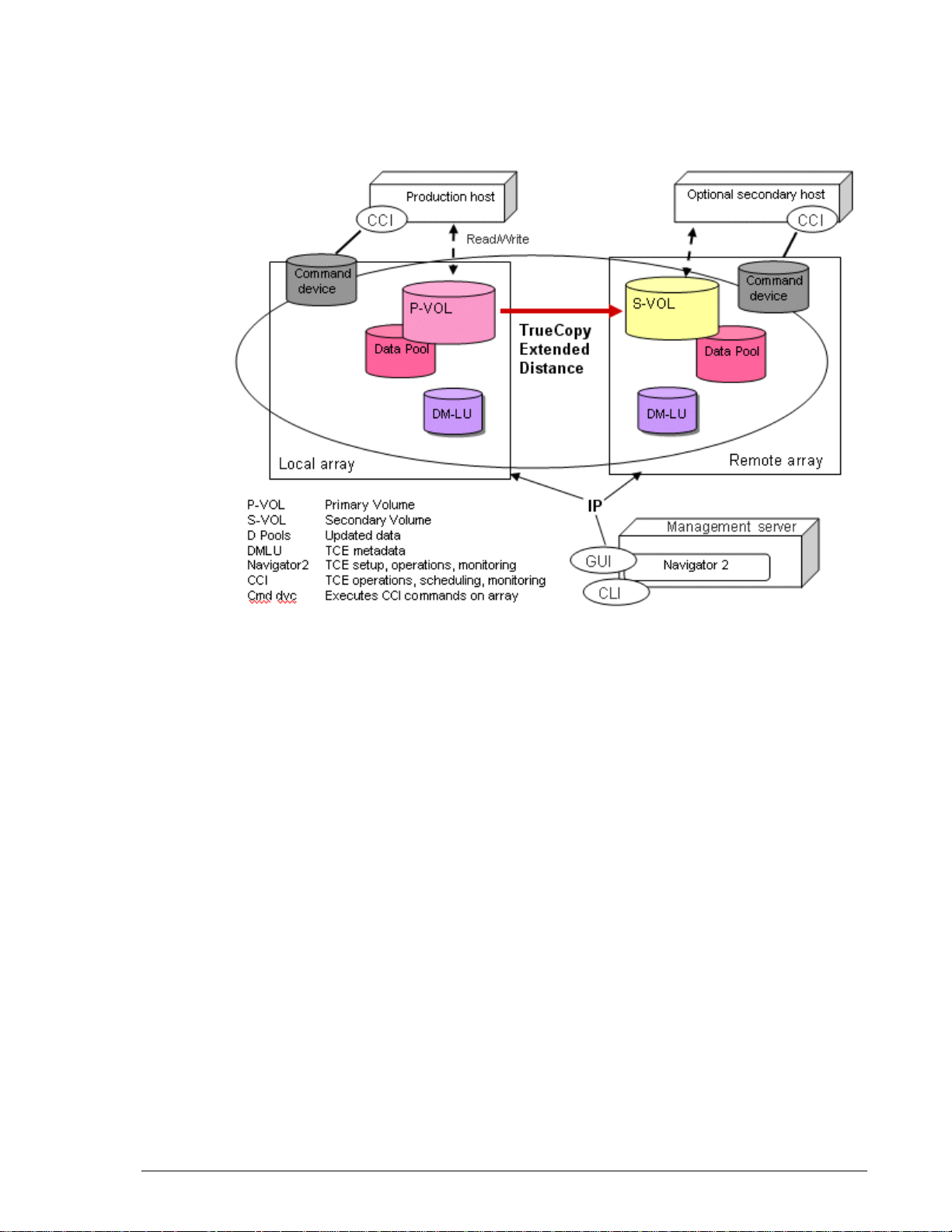
• Interface and command software, used to perform TCE operations.
Command software uses a command device (volume) to communicate
with the arrays.
Figure 1-1 shows a typical TCE environment.
•
Volume pairs
When the initial TCE copy is completed, the production and backup volumes
are said to be “Paired”. The two paired volumes are referred to as the
primary volume (P-VOL) and secondary volume (S-VOL). Each TCE pair
consists of one P-VOL and one S-VOL. When the pair relationship is
established, data flows from the P-VOL to the S-VOL.
While in the Paired status, new data is written to the P-VOL and then
periodically transferred to the S-VOL, according to the user-defined update
cycle.
When a pair is “split”, the data flow between the volumes stops. At this time,
all the differential data that has accumulated in the local array since the last
update is copied to the S-VOL. This insures that its data is the same as the
P-VOL’s and is consistent and usable data.
During normal TCE operations, the P-VOL remains available for read/write
from the host. When the pair is split, the S-VOL also is available for read/
write operations from a host.
Figure 1-1: Typical TCE Environment
Overview 1–3
Hitachi AMS 2000 Family TrueCopy Extended Distance User Guide
Page 24

Data pools
Data from the host is continually updated to the P-VOL, as it occurs. The
data pool on the local side stores the changed data that accumulates before
the next the update cycle. The local data pool is used to update the S-VOL.
Data that accumulates in the data pool is referred to as differential data
because it contains the difference data between the P-VOL and S-VOL.
The data in the S-VOL following an update is complete, consistent, and
usable data. When the next update is to begin, this consistent data is copied
to the remote data pool. This data pool is used to maintain previous pointin-time copies of the S-VOL, which are used in the event of failback.
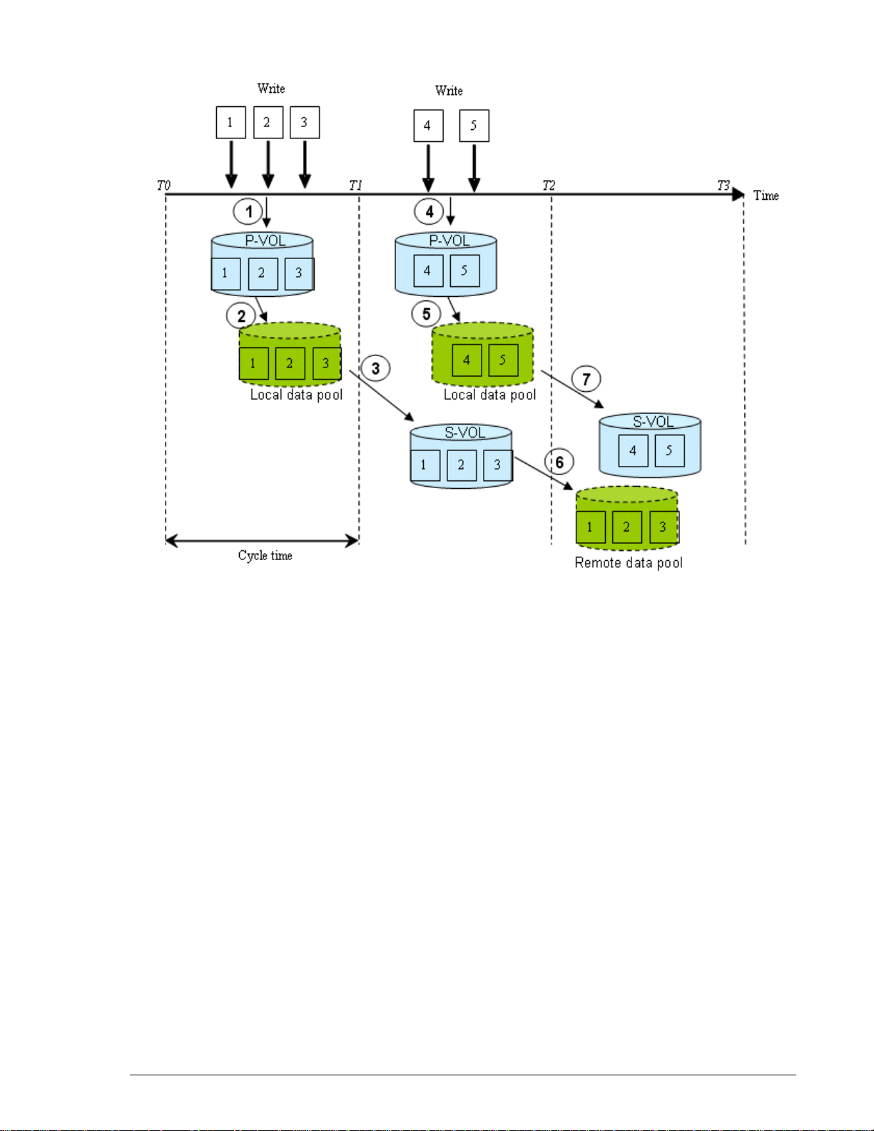
Guaranteed write order and the update cycle
S-VOL data must have the same order in which the host updates the P-VOL.
When write order is guaranteed, the S-VOL has data consistency with the
P-VOL.
As explained in the previous section, data is copied from the P-VOL and local
data pool to the S-VOL following the update cycle. When the update is
complete, S-VOL data is identical to P-VOL data at the end of the cycle.
Since the P-VOL continues to be updated while and after the S-VOL is being
updated, S-VOL data and P-VOL data are not identical.
However, the S-VOL and P-VOL can be made identical when the pair is split.
During this operation, all differential data in the local data pool is
transferred to the S-VOL, as well as all cached data in host memory. This
cached data is flushed to the P-VOL, then transferred to the S-VOL as part
of the split operation, thus ensuring that the two are identical.
If a failure occurs during an update cycle, the data in the update is
inconsistent. Write order in the S-VOL is nevertheless guaranteed — at the
point-in-time of the previous update cycle, which is stored in the remote
data pool.
Figure 1-2 shows how S-VOL data is maintained at one update cycle back
of P-VOL data.
1–4 Overview
Hitachi AMS 2000 Family TrueCopy Extended Distance User Guide
Page 25
•
Extended update cycles
If inflow to the P-VOL increases, all of the update data may not be sent
within the cycle time. This causes the cycle to extend beyond the userspecified cycle time.
As a result, more update data in the P-VOL accumulates to be copied at the
next update. Also, the time difference between the P-VOL data and S-VOL
data increases, which degrades the recovery point value. In Figure 1-2, if a
failure occurs at the primary site immediately before time T3, for example,
data consistency in the S-VOL during takeover is P-VOL data at time T1.
When inflow decreases, updates again complete within the cycle time. Cycle
time should be determined according to a realistic assessment of write
workload, as discussed in Chapter 2, Plan and design — sizing data pools
and bandwidth.
Figure 1-2: Update Cycles and Differential Data
Overview 1–5
Hitachi AMS 2000 Family TrueCopy Extended Distance User Guide
Page 26
Consistency groups
Application data often spans more than one volume. With TCE, it is possible
to manage operations spanning multiple volumes as a single group. In a
consistency group (CTG), all primary logical volumes are treated as a single
entity.
Managing primary volumes as a consistency group allows TCE operations to
be performed on all volumes in the group concurrently. Write order in
secondary volumes is guaranteed across application logical volumes.
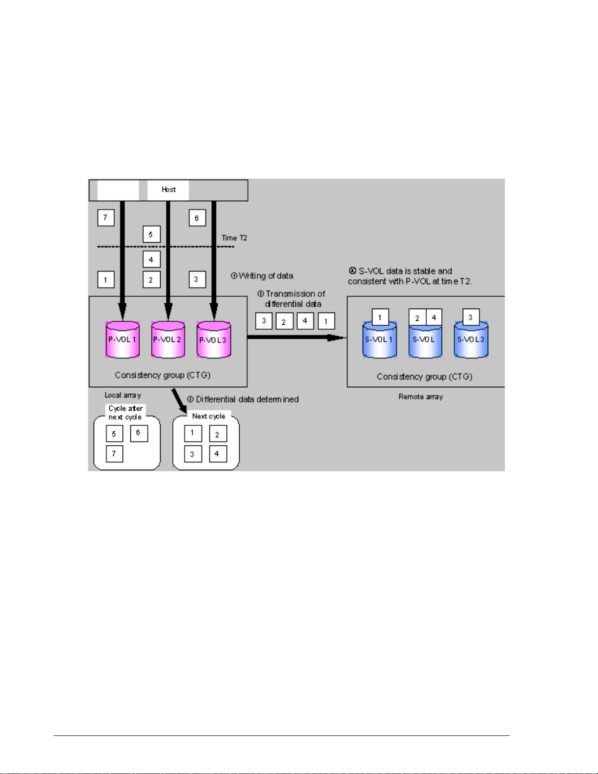
Figure 1-3 shows TCE operations with a consistency group.
•
Figure 1-3: TCE Operations with Consistency Groups
In this illustration, observe the following:
• The P-VOLs belong to the same consistency group. The host updates
the P-VOLs as required (1).
• The local array identifies the differential data in the P-VOLs when the
cycle is started (2) in an atomic manner. The differential data of the
group of the P-VOLs are determined at time T2.
• The local array transfers the differential data to the corresponding SVOLs (3). When all differential data is transferred, each S-VOL is
identical to its P-VOL at time T2 (4).
• If pairs are split or deleted, the local array stops the cycle update for
the consistency group. Differential data between P-VOLs and S-VOLs is
determined at that time. All differential data is sent to the S-VOLs, and
the split or delete operations on the pairs completes. S-VOLs maintain
1–6 Overview
Hitachi AMS 2000 Family TrueCopy Extended Distance User Guide
Page 27

data consistency across pairs in the consistency group. The pair that is
using different data pool can be belongs to the same consistency group.
Differential Management LUs (DMLU)
The DMLU is an exclusive volume used for storing TrueCopy information
when the local or remote array is powered down. The DMLU is hidden from
a host. User setup is required on the local and remote arrays.
TCE interfaces
TCE can be setup, used and monitored using of the following interfaces:
• The GUI (Hitachi Storage Navigator Modular 2 Graphical User
Interface), which is a browser-based interface from which TCE can be
setup, operated, and monitored. The GUI provides the simplest method
for performing operations, requiring no previous experience. Scripting
is not available.
• CLI (Hitachi Storage Navigator Modular 2 Command Line Interface),
from which TCE can be setup and all basic pair operations can be
performed—create, split, resynchronize, restore, swap, and delete. The
GUI also provides these functionalities. CLI also has scripting capability.
• CCI (Hitachi Command Control Interface (CCI), which is used to display
volume information and perform all copying and pair-managing
operations. CCI provides a full scripting capability which can be used to
automate replication operations. CCI requires more experience than
the GUI or CLI. CCI is required for performing failover and fall back
operations, and, on Windows 2000 Server, mount/unmount operations.
HDS recommends using the GUI to begin operations for new users with no
experience with CLI or CCI. Users who are new to replication software but
have CLI experience in managing arrays may want to continue using CLI,
though the GUI is an option. The same recommendation applies to CCI
users.
Overview 1–7
Hitachi AMS 2000 Family TrueCopy Extended Distance User Guide
Page 28

1–8 Overview
Hitachi AMS 2000 Family TrueCopy Extended Distance User Guide
Page 29

2
Plan and design — sizing
data pools and bandwidth
This chapter provides instructions for measuring write-workload
and sizing data pools and bandwidth.
Plan and design workflow
Assessing business needs — RPO and the update cycle
Measuring write-workload
Calculating data pool size
Determining bandwidth
Plan and design — sizing data pools and bandwidth 2–1
Hitachi AMS 2000 Family TrueCopy Extended Distance User Guide
Page 30

Plan and design workflow
You design your TCE system around the write-workload generated by your
host application. Data pools and bandwidth must be sized to accommodate
write-workload. This chapter helps you perform these tasks as follows:
• Assess business requirements regarding how much data your operation
must recover in the event of a disaster.
• Measure write-workload. This metric is used to ensure that data pool
size and bandwidth are sufficient to hold and pass all levels of I/O.
• Calculate data pool size. Instructions are included for matching data
pool capacity to the production environment.
• Calculate remote path bandwidth: This will make certain that you can
copy your data to the remote site within your update cycle.
Assessing business needs — RPO and the update cycle
In a TCE system, the S-VOL will contain nearly all of the data that is in the
P-VOL. The difference between them at any time will be the differential data
that accumulates during the TCE update cycle.
This differential data accumulates in the local data pool until the update
cycle starts, then it is transferred over the remote data path.
Update cycle time is a uniform interval of time during which differential data
copies to the S-VOL. You will define the update cycle time when creating the
TCE pair.
The update cycle time is based on:
• the amount of data written to your P-VOL
• the maximum amount of data loss your operation could survive during
a disaster.
The data loss that your operation can survive and remain viable determines
to what point in the past you must recover.
An ho ur ’s wo rth of da ta l os s me an s t hat yo ur re cov er y p oi nt i s o ne hou r a go .
If disaster occurs at 10:00 am, upon recovery your restart will resume
operations with data from 9:00 am.
Fifteen minutes worth of data loss means that your recovery point is 15
minutes prior to the disaster.
You must determine your recovery point objective (RPO). You can do this by
measuring your host application’s write-workload. This shows the amount
of data written to the P-VOL over time. You or your organization’s decisionmakers can use this information to decide the number of business
transactions that can be lost, the number of hours required to key in lost
data and so on. The result is the RPO.
2–2 Plan and design — sizing data pools and bandwidth
Hitachi AMS 2000 Family TrueCopy Extended Distance User Guide
Page 31

Measuring write-workload
Bandwidth and data pool size are determined by understanding the writeworkload placed on the primary volume from the host application.
• After the initial copy, TCE only copies changed data to the S-VOL.
• Data is changed when the host application writes to storage.
• Write-workload is a measure of changed data over a period of time.
When you know how much data is changing, you can plan the size of your
data pools and bandwidth to support your environment.
Collecting write-workload data
Workload data is collected using your operating system’s performance
monitoring feature. Collection should be performed during the busiest time
of month, quarter, and year so you can be sure your TCE implementation
will support your environment when demand is greatest. The following
procedure is provided to help you collect write-workload data.
To collect workload data
1. Using your operating system’s performance monitoring software, collect
the following:
- Disk-write bytes-per-second for every physical volume that will be
replicated.
- Collect this data at 10 minute intervals and over as long a period
as possible. Hitachi recommends a 4-6 week period in order to
accumulate data over all workload conditions including times when
the demands on the system are greatest.
•
2. At the end of the collection period, convert the data to MB/second and
import into a spreadsheet tool. In Figure 2-1, Write-Workload
Spreadsheet, column C shows an example of collected raw data over 10-
minute segments.
Plan and design — sizing data pools and bandwidth 2–3
Hitachi AMS 2000 Family TrueCopy Extended Distance User Guide
Page 32

•
Figure 2-1: Write-Workload Spreadsheet
Fluctuations in write-workload can be seen from interval to interval. To
calculate data pool size, the interval data will first be averaged, then used
in an equation. (Your spreadsheet at this point would have only rows B and
C populated.)
Calculating data pool size
In addition to write-workload data, cycle time must be known. Cycle time is
the frequency that updates are sent to the remote array. This is a userdefined value that can range from 30 seconds to 1 hour. The default cycle
time is 5-minutes (300 seconds). If consistency groups are used, the
minimum must be 30 seconds for one CTG, increasing 30 seconds for each
additional CTG, up to 16. Since the data pool stores all updated data that
accumulates during the cycle time, the longer the cycle time, the larger the
data pool must be. For more information on cycle time, see the discussion
in Assessing business needs — RPO and the update cycle on page 2-2, and
also Changing cycle time on page 9-8.
To calculate TCE data pool capacity
1. Using write-workload data imported into a spreadsheet tool and your
cycle time, calculate write rolling-averages, as follows. (Most
spreadsheet tools have an average function.)
- If cycle time is 1 hour, then calculate 60 minute rolling averages.
Do this by arranging the values in six 10-minute intervals.
- If cycle time is 30 minutes, then calculate 30 minute rolling
averages, arranging the values in three 10-minute intervals.
2–4 Plan and design — sizing data pools and bandwidth
Hitachi AMS 2000 Family TrueCopy Extended Distance User Guide
Page 33

Example rolling-average procedure for cycle time in Microsoft
Excel
Cycle time in the following example is 1 hour; rolling averages are
calculated using six 10-minute intervals.
a. After converting workload data into the spreadsheet (Figure 2-1,
Write-Workload Spreadsheet), in cell E4 type, =average(b2:b7),
and press Enter.
This instructs the tool to calculate the average value in cells B2
through B7 (six 10-minute intervals) and populate cell E4 with that
data. (The calculations used here are for example purposes only.
Base your calculations on your cycle time.)
b. Copy the value that displays in E4.
c. Highlight cells E5 to the E cell in the last row of workload data in the
spreadsheet.
d. Right-click the highlighted cells and select the Paste option.
Excel maintains the logic and increments the formula values initially
entered in E4. It then calculates all the 60-minute averages for every
10-minute increment, and populates the E cells, as shown in
Figure 2-2.
•
•
Figure 2-2: Rolling Averages Calculated Using 60 Minute Cycle Time
Plan and design — sizing data pools and bandwidth 2–5
Hitachi AMS 2000 Family TrueCopy Extended Distance User Guide
Page 34

For another perspective, you can graph the data, as shown in
Figure 2-3.
•
Figure 2-3: 60-Minute Rolling Averages Graphed Over Raw Data
2. From the spreadsheet or graph, locate the largest value in the E column.
This is your Peak Rolling Average (PRA) value. Use the PRA to calculate
the cumulative peak data change over cycle time. The following formula
calculates the largest expected data change over the cycle time. This will
ensure that you do not overflow your data pool.
(PRA in MB/sec) x (cycle time seconds) = (Cumulative peak data
change)
For example, if the PRA is 3 MB/sec, and the cycle time is 3600 seconds
(1 hour), then:
3MB/sec x 3600 seconds = 10,800 MB
This shows the maximum amount of changed data (pool data) that you
can expect in a 60 minute time period. This is the base data pool size
required for TCE.
3. Hitachi recommends a 20-percent safety factor for data pools. Calculate
a safety factor with the following formula:
(Combined base data pool size) x 1.2. For example:
529,200 MB x 1.2 = 635,040 MB
2–6 Plan and design — sizing data pools and bandwidth
Hitachi AMS 2000 Family TrueCopy Extended Distance User Guide
Page 35

4. It is also recommended that annual increases in data transactions be
factored into data pool sizing. This is done to minimize reconfiguration
in the future. Do this by multiplying the pool size with safety factor by
the percentage of expected annual growth. For example:
635,040 MB x 1.2 (20 percent growth rate for per year)
= 762,048 MB
Repeat this step for each year the solution will be in place.
5. Convert to gigabytes, dividing by 1,000. For example:
762,048 MB / 1,000 = 762 GB
This is the size of the example data pool with safety and growth (2nd
year) factored in.
Data pool key points
• Data pools must be set up on the local array and the remote array.
• The data pool must be on the same controller as the P-VOL and VVOL(s).
• Up to 64 LUs can be assigned to a data pool.
• Plan for highest workload and multi-year growth.
• For set up information, see Setting up data pools on page 6-12.
Plan and design — sizing data pools and bandwidth 2–7
Hitachi AMS 2000 Family TrueCopy Extended Distance User Guide
Page 36

Determining bandwidth
The purpose of this section is to ensure that you have sufficient bandwidth
between the local and remote arrays to copy all your write data in the timeframe you prescribe. The goal is to size the network so that it is capable of
transferring estimated future write workloads.
TCE requires two remote paths, each with a minimum bandwidth of 1.5 Mbs.
To determine the bandwidth
1. Graph the data in column “C” in the Write-Workload Spreadsheet on
page 2-4.
2. Locate the highest peak. Based on your write-workload measurements,
this is the greatest amount of data that will need to be transferred to the
remote array. Bandwidth must accommodate maximum possible
workload to insure that the system does not become subject to its
capacity being exceeded. This would cause further problems, such as the
new write data backing up in the data pool, update cycles becoming
extended, and so on.
3. Though the highest peak in your workload data should be used for
determining bandwidth, you should also take notice of extremely high
peaks. In some cases a batch job, defragmentation, or other process
could be driving workload to abnormally high levels. It is sometimes
worthwhile to review the processes that are running. After careful
analysis, it may be possible to lower or even eliminate some spikes by
optimizing or streamlining high-workload processes. Changing the
timing of a process may lower workload.
4. Although bandwidth can be increased, Hitachi recommends that
projected growth rate be factored over a 1, 2, or 3 year period.
Table 2-1 shows TCE bandwidth requirements.
Table 2-1: Bandwidth Requirements
Average Inflow Bandwidth Requirements WAN Types
.08 - .149 MB/s 1.5 Mb/s or more T1
.15 - .299 MB/s 3 Mb/s or more T1 x two lines
.3 - .599 MB/s 6 Mb/s or more T2
.6 - 1.199 MB/s 12 Mb/s or more T2 x two lines
1.2 - 4.499 MB/s 45 Mb/s or more T3
4.500 - 9.999 MB/s 100 Mb/s or more Fast Ethernet
2–8 Plan and design — sizing data pools and bandwidth
Hitachi AMS 2000 Family TrueCopy Extended Distance User Guide
Page 37

3
Plan and design — remote
path
A remote path is required for transferring data from the local
array to the remote array. This chapter provides network and
bandwidth requirements, and supported remote path
configurations.
Remote path requirements
Remote path configurations
Using the remote path — best practices
Plan and design — remote path 3–1
Hitachi AMS 2000 Family TrueCopy Extended Distance User Guide
Page 38

Remote path requirements
The remote path is the connection used to transfer data between the local
array and remote array. TCE supports Fibre Channel and iSCSI port
connectors and connections. The connections you use must be either one or
the other: they cannot be mixed.
The following kinds of networks are used with TCE:
• Local Area Network (LAN), for system management. Fast Ethernet is
required for the LAN.
• Wide Area Network (WAN) for the remote path. For best performance:
- A Fibre Channel extender is required.
- iSCSI connections may require a WAN Optimization Controller
(WOC).
Figure 3-1 shows the basic TCE configuration with a LAN and WAN.
•
Figure 3-1: Remote Path Configuration
Requirements are provided in the following:
• Management LAN requirements on page 3-3
• Remote data path requirements on page 3-3
• WAN optimization controller (WOC) requirements on page 3-4
• Fibre channel extender connection on page 3-9.
3–2 Plan and design — remote path
Hitachi AMS 2000 Family TrueCopy Extended Distance User Guide
Page 39

Management LAN requirements
Fast Ethernet is required for an IP LAN.
Remote data path requirements
This section discusses the TCE remote path requirements for a WAN
connection. This includes the following:
•Types of lines
•Bandwidth
• Distance between local and remote sites
• WAN Optimization Controllers (WOC) (optional)
For instructions on assessing your system’s I/O and bandwidth
requirements, see:
• Measuring write-workload on page 2-3
• Determining bandwidth on page 2-8
Table 3-1 provides remote path requirements for TCE. A WOC may also be
required, depending on the distance between the local and remote sites and
other factors listed in Table 3-3.
•
Table 3-1: Remote Data Path Requirements
Item Requirements
Bandwidth • Bandwidth must be guaranteed.
• Bandwidth must be 1.5 Mb/s or more for each pair.
100 Mb/s recommended.
• Requirements for bandwidth depend on an average
inflow from the host into the array.
•See Table 2-1 on page 2-8 for bandwidth
requirements.
Remote Path Sharing • The remote path must be dedicated for TCE pairs.
• When two or more pairs share the same path, a
WOC is recommended for each pair
•
•
.
Table 3-2 shows types of WAN cabling and protocols supported by TCE and
those not supported.
•
Table 3-2: Supported, Not Supported WAN Types
WAN Types
Supported • Dedicated Line (T1, T2, T3 etc)
Not-supported • ADSL, CATV, FTTH, ISDN
Plan and design — remote path 3–3
Hitachi AMS 2000 Family TrueCopy Extended Distance User Guide
Page 40

WAN optimization controller (WOC) requirements
WAN Optimization Controller (WOC) is a network appliance that enhances
WAN performance by accelerating long-distance TCP/IP communications.
TCE copy performance over longer distances is significantly increased when
WOC is used. A WOC guarantees bandwidth for each line.
•Use Table 3-3 to determine whether your TCE system requires the
addition of a WOC.
• Table 3-4 shows the requirements for WOCs.
•
Table 3-3: Conditions Requiring a WOC
Item Condition
Latency, Distance • If round trip time is 5 ms or more, or distance
between the local site and the remote site is 100
miles (160 km) or further, WOC is highly
recommended.
WAN Sharing • If two or more pairs share the same WAN, A WOC
is recommended for each pair.
•
Table 3-4: WOC Requirements
Item Requirements
LAN Interface • Gigabit Ethernet or fast Ethernet must be
supported.
Performance • Data transfer capability must be equal to or more
than bandwidth of WAN.
Functions • Traffic shaping, bandwidth throttling, or rate
limiting must be supported. These functions reduce
data transfer rates to a value input by the user.
• Data compression must be supported.
• TCP acceleration must be supported.
3–4 Plan and design — remote path
Hitachi AMS 2000 Family TrueCopy Extended Distance User Guide
Page 41

Remote path configurations
TCE supports both Fibre Channel and iSCSI connections for the remote
path.
• Two remote paths must be set up between, one per controller. This
ensures that an alternate path is available in the event of link failure
during copy operations.
• Paths can be configured from:
- Local controller 0 to remote controller 0 or 1
- Local controller 1 to remote controller 0 or 1
• Paths can connect a port A with a port B, and so on. Hitachi
recommends making connections between the same controller/port,
such as port 0B to 0B, and 1 B to 1 B, for simplicity. Ports can be used
for both host I/O and replication data.
The following sections describe supported Fibre Channel and iSCSI path
configurations. Recommendations and restrictions are included.
Fibre channel
The Fibre Channel remote data path can be set up in the following
configurations:
• Direct connection
• Single Fibre Channel switch and network connection
• Double FC switch and network connection
• Wavelength Division Multiplexing (WDM) and dark fibre extender
The array supports direct or switch connection only. Hub connections are
not supported.
General recommendations
The following is recommended for all supported configurations:
• TCE requires one path between the host and local array. However, two
paths are recommended; the second path can be used in the event of a
path failure.
Plan and design — remote path 3–5
Hitachi AMS 2000 Family TrueCopy Extended Distance User Guide
Page 42

Direct connection
Figure 3-2 illustrates two remote paths directly connecting the local and
remote arrays. This configuration can be used when distance is very short,
as when creating the initial copy or performing data recovery while both
arrays are installed at the local site.
•
Figure 3-2: Direct FC Connection
3–6 Plan and design — remote path
Hitachi AMS 2000 Family TrueCopy Extended Distance User Guide
Page 43

Single FC switch, network connection
Switch connections increase throughput between the arrays. Figure 3-3
illustrates two remote paths routed through one FC switch and one FC
network to make the connection to the remote site.
•
Figure 3-3: Single FC Switch, Network Connection
Recommendations
• While this configuration may be used, it is not recommended since
failure in an FC switch or the network would halt copy operations.
• Separate switches should be set up for host I/O to the local array and
for data transfer between arrays. Using one switch for both functions
results in deteriorated performance.
Plan and design — remote path 3–7
Hitachi AMS 2000 Family TrueCopy Extended Distance User Guide
Page 44

Double FC switch, network connection
Figure 3-4 illustrates two remote paths using two FC switches and two FC
networks to make the connection to the remote site.
•
Figure 3-4: Double FC Switches, Networks Connection
Recommendations
• Separate switches should be set up for host I/O to the local array and
for data transfer between arrays. Using one switch for both functions
results in deteriorated performance.
3–8 Plan and design — remote path
Hitachi AMS 2000 Family TrueCopy Extended Distance User Guide
Page 45

Fibre channel extender connection
Channel extenders convert Fibre Channel to FCIP or iFCP, which allows you
to use IP networks and significantly improve performance over longer
distances.
Figure 3-5 illustrates two remote paths using two FC switches, Wavelength
Division Multiplexor (WDM) extender, and dark fibre to make the connection
to the remote site.
•
Figure 3-5: Fibre Channel Switches, WDM, Dark Fibre Connection
Recommendations
• Only qualified components are supported.
For more information on WDM, see Appendix E, Wavelength Division
Multiplexing (WDM) and dark fibre.
Plan and design — remote path 3–9
Hitachi AMS 2000 Family TrueCopy Extended Distance User Guide
Page 46

Port transfer rate for Fibre channel
The communication speed of the Fibre Channel port on the array must
match the speed specified on the host port. These two ports—Fibre Channel
port on the array and host port—are connected via the Fibre Channel cable.
Each port on the array must be set separately.
•
Table 3-5: Setting Port Transfer Rates
Set the remote array
port to
Manual mode
Auto mode
If the host port is set to
1 Gbps 1 Gbps
2 Gbps 2 Gbps
4 Gbps 4 Gbps
8 Gbps 8 Gbps
2 Gbps Auto, with max of 2 Gbps
4 Gbps Auto, with max of 4 Gbps
8 Gbps Auto, with max of 8 Gbps
Maximum speed is ensured using the manual settings.
You can specify the port transfer rate using the Navigator 2 GUI, on the Edit
FC Port screen (Settings/FC Settings/port/Edit Port button).
•
NOTE: If your remote path is a direct connection, make sure that the
array power is off when modifying the transfer rate to prevent remote path
blockage.
Find details on communication settings in the Hitachi AMS 2100/2300
Storage System Hardware Guide.
3–10 Plan and design — remote path
Hitachi AMS 2000 Family TrueCopy Extended Distance User Guide
Page 47

iSCSI
The iSCSI remote data path can be set up in the following configurations:
• Direct connection
• Local Area Network (LAN) switch connections
• Wide Area Network (WAN) connections
• WAN Optimization Controller (WOC) connections
Recommendations
The following is recommended for all supported configurations:
• Two paths should be configured from the host to the array. This
provides a backup path in the event of path failure.
Direct connection
Figure 3-6, illustrates two remote paths directly connecting the local and
remote arrays. Direct connections are used when the local and remote
arrays are set up at the same site. In this case, category 5e or 6 copper LAN
cable is recommended.
•
Figure 3-6: Direct iSCSI Connection
Recommendations
• When a large amount of data is to be copied to the remote site, the
initial copy between local side and remote systems may be performed
at the same location. In this case, category 5e or 6 copper LAN cable is
recommended.
Plan and design — remote path 3–11
Hitachi AMS 2000 Family TrueCopy Extended Distance User Guide
Page 48

Single LAN switch, WAN connection
Figure 3-7, illustrates two remote paths using one LAN switch and network
to the remote array.
•
Figure 3-7: Single-Switch Connection
Recommendations
• This configuration is not recommended because a failure in a LAN
switch or WAN would halt operations.
• Separate LAN switches and paths should be used for host-to-array and
array-to-array, for improved performance.
3–12 Plan and design — remote path
Hitachi AMS 2000 Family TrueCopy Extended Distance User Guide
Page 49

Multiple LAN switch, WAN connection
Figure 3-8, illustrates two remote paths using multiple LAN switches and
WANs to make the connection to the remote site.
•
Figure 3-8: Multiple-Switch and WAN Connection
Recommendations
• Separate LAN switches and paths should be used for the host-to-array
and the array-to-array paths for better performance and to provide a
backup.
Plan and design — remote path 3–13
Hitachi AMS 2000 Family TrueCopy Extended Distance User Guide
Page 50

Single LAN switch, WOC, WAN connection
WOCs may be required for TCE, depending on your system’s bandwidth,
latency, and so on. Use of a WOC improves performance. See WAN
optimization controller (WOC) requirements on page 3-4 for more
information.
Figure 3-9, illustrates two remote paths using a single LAN switch, WOC,
and WAN to make the connection to the remote site.
•
Figure 3-9: Single Switch, WOC, and WAN Connection
3–14 Plan and design — remote path
Hitachi AMS 2000 Family TrueCopy Extended Distance User Guide
Page 51

Multiple LAN switch, WOC, WAN connection
Figure 3-10, illustrates two remote connections using multiple LAN
switches, WOCs, and WANs to make the connection to the remote site.
•
Figure 3-10: Connection Using Multiple Switch, WOC, WAN
Recommendations
• If a Gigabit Ethernet port (1000BASE-T) is provided on the WOC, the
LAN switch to the WOC is not required. Connect array ports 0B and 1B
to the WOC directly. If your WOC does not have 1Gbps ports, the LAN
switch is required.
• Using separate LAN switch, WOC and WAN for each remote path
ensures that data copy automatically continues on the second path in
the event of a path failure.
Plan and design — remote path 3–15
Hitachi AMS 2000 Family TrueCopy Extended Distance User Guide
Page 52

Multiple array, LAN switch, WOC connection with single WAN
Figure 3-11, shows two local arrays connected to two remote arrays, each
via a LAN switch and WOC.
Figure 3-11: Multiple Array Connection Using Single WAN
Recommendations
• If a Gigabit Ethernet port (1000BASE-T) is provided on the WOC, the
LAN switch to the WOC is not required. Connect array ports 0B and 1B
to the WOC directly. If your WOC does not have 1Gbps ports, the LAN
switch is required.
• You can reduce the number of switches by using a switch with VLAN
capability. If a VLAN switch is used, port 0B of local array 1 and the
WOC1 should be in one LAN (VLAN1); port 0B of local array 2 and
WOC3 should be in another LAN (VLAN2). Connect the VLAN2 port
directly to Port 0B of the local array 2 and WOC3.
3–16 Plan and design — remote path
Hitachi AMS 2000 Family TrueCopy Extended Distance User Guide
Page 53

Multiple array, LAN switch, WOC connection with two WANs
Figure 3-12, shows two local arrays connected to two remote arrays, each
via two LAN switches, WANs, and WOCs.
•
Figure 3-12: Multiple Array Connection Using Two WANs
Recommendations
• If a Gigabit Ethernet port (1000BASE-T) is provided on the WOC, the
LAN switch to the WOC is not required. Connect array ports 0B and 1B
to the WOC directly. If your WOC does not have 1Gbps ports, the LAN
switch is required.
• You can reduce the number of switches by using a switch with VLAN
capability. If a VLAN switch is used, port 0B of local array 1 and WOC1
should be in one LAN (VLAN1); port 0B of local array 2 and WOC3
should be in another LAN (VLAN2). Connect the VLAN2 port directly to
Port 0B of the local array 2 and WOC3.
Plan and design — remote path 3–17
Hitachi AMS 2000 Family TrueCopy Extended Distance User Guide
Page 54

Supported connections between various types of arrays
Hitachi AMS2100, AMS2300, or AMS2500 can be connected with Hitachi
WMS100, AMS200, AMS500, or AMS1000. The following table shows the
supported connections between various types of arrays.
Table 3-6: Supported Connections between Various Types of Arrays
Remote Side Array Type
Local Side
Array Type
WMS100
AMS200
AMS200 AMS500 AMS1000 AMS2100 AMS2300 AMS2500 HUS100
WMS100
AMS200
AMS500 Not
AMS1000 Not
AMS2100 Not
AMS2300 Not
AMS2500 Not
HUS100 Not
Not
supported
Supported
supported
supported
supported
supported
supported
Not
supported
Available Available Available Available Available Available Available
Available Available Available Available Available Available Available
Available Available Available Available Available Available Available
Available Available Available Available Available Available Available
Available Available Available Available Available Available Available
Available Available Available Available Available Available Available
Not
supported
Not
supported
Not
supported
Not
supported
Not
supported
Notes when Connecting Hitachi AMS2000 Series to other arrays
• The maximum number of pairs that can be created is limited to the
maximum number of pairs supported by the arrays, whichever is fewer.
• The firmware version of AMS500/1000 must be 0780/A or later when
connecting with AMS2100, AMS2300, or AMS2500 of the H/W Rev. is
0100.
Not
supported
• The firmware version of AMS500/1000 must be 0786/A or later when
connecting with AMS2100, AMS2300, or AMS2500 of the H/W Rev. is
0200.
• The firmware version of AMS2100, AMS2300, or AMS2500 must be
08B7/B or later when connecting with HUS100.
• If a Hitachi Unified Storage as the local array connects to an AMS2010,
AMS2100, AMS2300, or AMS2500 with under 08B7/B as the remote
array, the remote path will be blocked along with the following
message:
• For Fibre Channel connection:
The target of remote path cannot be connected(Port-xy)
Path alarm(Remote-X,Path-Y)
• For iSCSI connection:
• Path Login failed
3–18 Plan and design — remote path
Hitachi AMS 2000 Family TrueCopy Extended Distance User Guide
Page 55

• The bandwidth of the remote path to AMS500/1000 must be 20 Mbps
or more.
• The pair operation of AMS500/1000 cannot be done from Navigator 2.
• Because AMS500 or AMS1000 has only one data pool per controller, the
user cannot specify which data pool to use. For that reason, when
connecting AMS500 or AMS1000 with AMS2100, AMS2300, or
AMS2500, the specifications about the data pools become the
followings:
- When AMS500 or AMS1000 is the local array, the data pool 0 is
selected if the LUN of the S-VOL is even, and the data pool 1 is
selected if it is odd. In the configuration that the LU numbers of
the S-VOL include odd pairs and even pairs, both data pool 0 and
data pool 1 are required.
- When AMS2100, AMS2300, or AMS2500 is the local array, the data
pool number is ignored even if specified. The data pool 0 is
selected the owner controller of the S-VOL is 0, and data pool 1 is
selected if it is 1.
• AMS500 or AMS1000 cannot use the functions that are newly
supported by AMS2100, AMS2300, or AMS2500.
• AMS2100, AMS2300, or AMS2500 cannot use the functions that are
newly supported by HUS100.
Plan and design — remote path 3–19
Hitachi AMS 2000 Family TrueCopy Extended Distance User Guide
Page 56

Using the remote path — best practices
The following best practices are provided to reduce and eliminate path
failure.
• If both arrays are powered off, power-on the remote array first.
• When powering down both arrays, turn off the local array first.
• Before powering off the remote array, change pair status to Split. In
Paired or Synchronizing status, a power-off results in Failure status on
the remote array.
• If the remote array is not available during normal operations, a
blockage error results with a notice regarding SNMP Agent Support
Function and TRAP. In this case, follow instructions in the notice.
Path blockage automatically recovers after restarting. If the path
blockage is not recovered when the array is READY, contact Hitachi
Customer Support.
• Power off the arrays before performing the following operation:
- Setting or changing the fibre transfer rate
3–20 Plan and design — remote path
Hitachi AMS 2000 Family TrueCopy Extended Distance User Guide
Page 57

4
Plan and design—arrays,
volumes and operating
systems
This chapter provides the information you need to prepare your
arrays and volumes for TCE operations
Planning arrays—moving data from earlier AMS models
Planning logical units for TCE volumes
Operating system recommendations and restrictions
Maximum supported capacity
Plan and design—arrays, volumes and operating systems 4–1
Hitachi AMS 2000 Family TrueCopy Extended Distance User Guide
Page 58

Planning workflow
Planning a TCE system consists of determining business requirements for
recovering data, measuring production write-workload and sizing data pools
and bandwidth, designing the remote path, and planning your arrays and
volumes. This chapter discusses arrays and volumes as follows:
• Requirements and recommendations for using previous versions of AMS
with the AMS 2000 Family.
• Logical unit set up: LUs must be set up on the arrays before TCE is
implemented. Volume requirements and specifications are provided.
• Operating system considerations: Operating systems have specific
restrictions for replication volumes pairs. These restrictions plus
recommendations are provided.
• Maximum Capacity Calculations: Required to make certain that your
array has enough capacity to support TCE. Instructions are provided for
calculating your volumes’ maximum capacity.
Planning arrays—moving data from earlier AMS models
Logical units on AMS 2100, 2300, and 2500 systems can be paired with
logical units on AMS 500 and AMS 1000 systems. Any combination of these
arrays may be used on the local and remote sides.
TCE pairs with WMS 100 and AMS 200 are not supported with AMS2100,
2300, or 2500.
When using the earlier model arrays, please observe the following:
• The bandwidth of the remote path to AMS 500 or AMS 1000 must be 20
Mbps or more.
• The maximum number of pairs between different model arrays is
limited to the maximum number of pairs supported by the smallest
array.
• The firmware version of AMS 500 or AMS 1000 must be 0780/A or later
when pairing with an AMS 2100, 2300, or 2500 where the hardware
Rev is 0100.
• The firmware version of AMS 500 or AMS 1000 must be 0786/A or later
when pairing with an AMS 2010, 2100, 2300, or 2500 where the
hardware Rev is 0200.
• Pair operations for AMS 500 and AMS 1000 cannot be performed using
the Navigator 2 GUI.
• AMS500 and AMS1000 cannot use functions that are newly supported
by AMS2100 or AMS2300.
• Because AMS 500 or AMS 1000 can have only one data pool per
controller, you are not able to specify which data pool to use. Because
of this, the data pool that is used is determined as follows:
- When AMS 500 or AMS 1000 is the local array, data pool 0 is used
if the S-VOL LUN is even; data pool 1 is used if the S-VOL LUN is
odd.
4–2 Plan and design—arrays, volumes and operating systems
Hitachi AMS 2000 Family TrueCopy Extended Distance User Guide
Page 59

- When an AMS 2100, 2300, or 2500 is the local array, the data pool
number is ignored even if specified. Data pool 0 is used if the SVOL owner-controller is 0, and data pool 1 is selected if the S-VOL
owner-controller is 1.
• The AMS 500 or AMS 1000 cannot use the functions that are newly
supported by AMS 2010, 2100, 2300, or 2500.
Planning logical units for TCE volumes
Please review the recommendations in the following sections before setting
up TrueCopy volumes. Also, review Requirements and specifications on
page 5-1.
Volume pair and data pool recommendations
• The P-VOL and S-VOL must be identical in size, with matching block
count. To check block size, in the Navigator 2 GUI, navigate to Groups/
RAID Groups/Logical Units tab. Click the desired LUN. On the popup
window that appears, review the Capacity field. This shows block size.
• The number of volumes within the same RAID group should be limited.
Pair creation or resynchronization for one of the volumes may impact
I/O performance for the others because of contention between drives.
When creating two or more pairs within the same RAID group,
standardize the controllers for the LUs in the RAID group. Also, perform
pair creation and resynchronization when I/O to other volumes in the
RAID group is low.
• Assign primary and secondary volumes and data pools to a RAID group
consisting of SAS drives, SAS7.2K drives, SSD drives, or SAS (SED)
drives to achieve best possible performance. SATA drives can be used,
however.
• When cascading TrueCopy and SnapShot pairs, assign a volume of the
SAS drives, the SAS7.2K drives, the SSD drives, or the SAS (SED)
drives and assign four or more disks to a data pool.
• Assign an LU consisting of four or more data disks, otherwise host and
copying performance may be lowered.
• Limit the I/O load on both local and remote arrays to maximize
performance. Performance on each array also affects performance on
the other array, as well as data pool capacity and the synchronization of
volumes. Therefore, it is best to assign a volume of SAS drives,
SAS7.2K drives, SSD drives, or SAS (SED) drives and assign four or
more disks (which have higher performance) than SATA drives, to a
data pool.
Plan and design—arrays, volumes and operating systems 4–3
Hitachi AMS 2000 Family TrueCopy Extended Distance User Guide
Page 60

Operating system recommendations and restrictions
The following sections provide operating system recommendations and
restrictions.
Host time-out
I/O time-out from the host to the array should be more than 60 seconds.
You can figure I/O time-out by increasing the remote path time limit times
6. For example, if the remote path time-out value is 27 seconds, set host I/
O time-out to 162 seconds (27 x 6) or more.
P-VOL, S-VOL recognition by same host on VxVM, AIX®, LVM
VxVM, AIX®, and LVM do not operate properly when both the P-VOL and SVOL are set up to be recognized by the same host. The P-VOL should be
recognized one host on these platforms, and the S-VOL recognized by a
different host.
HP server
When MC/Service Guard is used on a HP server, connect the host group
(Fibre Channel) or the iSCSI Target to HP server as follows:
For Fibre Channel interfaces
1. In the Navigator 2 GUI, access the array and click Host Groups in the
Groups tree view. The Host Groups screen displays.
2. Click the check box for the Host Group that you want to connect to the
HP server.
WARNING! Your host group changes will be applied to multiple ports. This
change will delete existing host group mappings and corresponding Host
Group IDs, corrupting or removing data associated with the host groups. To
keep specified host groups you do not want to remove, please cancel this
operation and make changes to only one host group at a time.
4–4 Plan and design—arrays, volumes and operating systems
Hitachi AMS 2000 Family TrueCopy Extended Distance User Guide
Page 61

3. Click Edit Host Group.
•
Plan and design—arrays, volumes and operating systems 4–5
Hitachi AMS 2000 Family TrueCopy Extended Distance User Guide
Page 62

The Edit Host Group screen appears.
4. Select the Options tab.
5. From the Platform drop-down list, select HP-UX. Doing this causes
Enable HP-UX Mode, Enable PSUE Read Reject Mode, and Enable
PSUE Read Reject Mode to be selected in the Additional Setting box.
6. Click OK. A message appears, click Close.
4–6 Plan and design—arrays, volumes and operating systems
Hitachi AMS 2000 Family TrueCopy Extended Distance User Guide
Page 63

For iSCSI interfaces
1. In the Navigator 2 GUI, access the array and click iSCSI Targets in the
Groups tree view. The iSCSI Targets screen displays.
2. Click the check box for the iSCSI Targets that you want to connect to the
HP server.
3. Click Edit Target. The Edit iSCSI Target screen appears.
4. Select the Options tab.
5. From the Platform drop-down list, select HP-UX. Doing this causes
“Enable HP-UX Mode” and “Enable PSUE Read Reject Mode” to be
selected in the Additional Setting box.
6. Click OK. A message appears, click Close.
Windows Server 2000
• A P-VOL and S-VOL cannot be made into a dynamic disk on Windows
Server 2000 and Windows Server™ 2008.
• Native OS mount/dismount commands can be used for all platforms,
except Windows Server 2000. The native commands on this
environment do not guarantee that all data buffers are completely
flushed to the volume when dismounting. In these instances, you must
use CCI to perform volume mount/unmount operations. For more
information on the CCI mount/unmount commands, see the Hitachi
AMS Command Control Interface (CCI) Reference Guide.
Windows Server 2003/2008
• A P-VOL and S-VOL can be made into a dynamic disk on Windows
Server 2003.
• In Windows Server™ 2008, refer to the Hitachi Adaptable Modular
Storage Command Control Interface (CCI) Reference Guide for the
restrictions when the mount/unmount command is used.
®
• Windows
resynchronized while retaining data on the S-VOL on the server
memory, the compatible backup cannot be collected. Therefore,
execute the CCI sync command immediately before re-synchronizing
the pair for the un-mounted S-VOL.
• In Windows Server™ 2008, set only the P-VOL of TCE to be recognized
by the host and let another host recognize the S-VOL.
• (CCI only) If a path detachment is caused by controller detachment or
Fibre Channel failure, and the detachment continues for longer than
one minute, the command device may not be recognized when
recovery occurs. In this case, execute the “re-scanning of the disks” in
Windows. If Windows cannot access the command device, though CCI
recognizes the command device, restart CCI.
• Volumes to be recognized by the same host: If you recognize the P-VOL
and S-VOL on Windows Server 2008 at the same time, it may cause an
error because the P-VOL and S-VOL have the same disk signature.
When the P-VOL and S-VOL have the same data, split the pair and then
may write for the un-mounted volume. If a pair is
Plan and design—arrays, volumes and operating systems 4–7
Hitachi AMS 2000 Family TrueCopy Extended Distance User Guide
Page 64

rewrite the disk signature so that they can retain different disk
signatures. You can use the uniqueid command to rewrite a disk
signature. See the Hitachi Adaptable Modular Storage Command
Control Interface (CCI) User's Guide for details.
Identifying P-VOL and S-VOL LUs on Windows
In Navigator 2, the P-VOL and S-VOL are identified by their LU number. In
Windows 2003 Server, LUs are identified by HLUN. To map LUN to HLUN on
Windows, proceed as follows. These instructions provide procedures for
iSCSI and Fibre Channel interfaces.
1. Identify the HLUN of your Windows disk.
a. From the Windows Server 2003 Control Panel, select Computer
Management>Disk Administrator.
b. Right-click the disk whose HLUN you want to know, then select
Properties. The number displayed to the right of “LUN” in the dialog
window is the HLUN.
2. Identify HLUN-to-LUN Mapping for the iSCSI interface as follows. (If
using Fibre Channel, skip to Step 3.)
a. In the Navigator 2 GUI, select the desired array.
b. In the array tree that displays, click the Group icon, then click the
iSCSI Targets icon in the Groups tree.
c. On the iSCSI Target screen, select an iSCSI target.
d. On the target screen, select the Logical Units tab. Find the
identified HLUN. The LUN displays in the next column.
e. If the HLUN is not present on a target screen, on the iSCSI Target
screen, select another iSCSI target and repeat Step 2d.
3. Identify HLUN-to-LUN Mapping for the Fibre Channel interface, as
follows:
a. In Navigator 2, select the desired array.
b. In the array tree that displays, click the Groups icon, then click the
Host Groups icon in the Groups tree.
WARNING! Your host group changes will be applied to multiple ports. This
change will delete existing host group mappings and corresponding Host
Group IDs, corrupting or removing data associated with the host groups. To
keep specified host groups you do not want to remove, please cancel this
operation and make changes to only one host group at a time.
c. On the Host Groups screen, select a Host group.
d. On the host group screen, select the Logical Units tab. Find the
identified H-LUN. The LUN displays in the next column.
e. If the HLUN is not present on a host group target screen, on the Host
Groups screen, select another Host group and repeat Step 3d.
4–8 Plan and design—arrays, volumes and operating systems
Hitachi AMS 2000 Family TrueCopy Extended Distance User Guide
Page 65

Windows 2000 or Windows Server and TCE Configuration
• Volume mount:
In order to make a consistent backup using a storage-based replication such
as TCE, you must have a way to flush the data residing on the server
memory to the array, so that the source volume of the replication has the
complete data.
You can flush the date on the server memory using the umount command
of CCI to unmount the volume. When using the umount command of CCI
for unmount, use the mount command of CCI for mount.
When using Window® 2000, do not use the mountvol command attached
to Windows® 2000 as standard and use the mount/umount command of
CCI even if you are using GUI or CLI of Navigator 2 for the pair operation.
If you are using Windows Server™ 2003, mountvol /P to flush data on the
server memory when un-mounting the volume is supported. Please
understand the specification of the command and run sufficient test before
you use it for your operation.
In Windows Server™ 2008, refer to the Hitachi Adaptable Modular Storage
Command Control Interface (CCI) Reference Guide for the restrictions when
mount/unmount command is used.
Windows® may write for the un-mounted volume. If a pair is
resynchronized while remaining the data to the S-VOL on the memory of the
server, the compatible backup cannot be collected. Therefore, execute the
sync command of CCI immediately before re-synchronizing the pair for the
un-mounted S-VOL.
For more detail about the CCI commands, see the Hitachi Adaptable
Modular Storage Command Control Interface (CCI) Reference Guide.
• Volumes to be recognized by the same host
If you recognize the P-VOL and S-VOL on Windows Server™ 2008 at the
same time, it may cause an error because the P-VOL and S-VOL have the
same disk signature. When the P-VOL and S-VOL have the same data, split
the pair and then rewrite the disk signature so that they can retain different
disk signatures. You can use the uniqueid command to rewrite a disk
signature. See the Hitachi Adaptable Modular Storage Command Control
Interface (CCI) User's Guide for the detail
• Command devices:
When a remote path detachment, which is caused by a controller
detachment or Fibre channel failure, continues for longer than one minute,
the command device may be unable to be recognized when recovery from
the remote path detachment is made. To make the recovery, execute the
"re-scanning of the disks" of Windows®. When Windows® cannot access
the command device, although CCI becomes able to recognize the
command device, restart CCI.
Plan and design—arrays, volumes and operating systems 4–9
Hitachi AMS 2000 Family TrueCopy Extended Distance User Guide
Page 66

Dynamic Disk in Windows 2000/Windows Server
n an environment of the Windows Server 2000/Windows Server, you cannot
use TCE pair volumes as dynamic disk. The reason for this restriction is
because in this case if you restart Windows or use the Rescan Disks
command after creating or re-synchronizing a TCE pair, there are cases
where the S-VOL is displayed as Foreign in Disk Management and become
inaccessable.
VMWare and TCE Configuration
When creating a backup of the virtual disk in the vmfs format using TCE,
shutdown the virtual machine that accesses the virtual disk, and then split
the pair.
If one LU is shared by multiple virtual machines, shutdown all the virtual
machines that share the LU when creating a backup. It is not recommended
to share one LU by multiple virtual machines in the configuration that
creates a backup using TCE.
4–10 Plan and design—arrays, volumes and operating systems
Hitachi AMS 2000 Family TrueCopy Extended Distance User Guide
Page 67

Concurrent Use of Dynamic Provisioning
• When the array firmware version is less than 0893/A, the DP-VOLs
created by Dynamic Provisioning cannot be set for a P-VOL or an S-VOL
of TCE. Moreover, when the array firmware version is less than 0893/A,
the DP-VOLs cannot be added to the data pool used by SnapShot and
TCE.
• Depending on the installed cache memory, Dynamic Provisioning and
TCE may not be unlocked at the same time. To unlock Dynamic
Provisioning and TCE at the same time, add cache memories. For the
capacity of the supported cache memory, refer to User Data Area of
Cache Memory on page 4-16.
• The data pool used by SnapShot and TCE cannot be used as a DP pool
of Dynamic Provisioning. Moreover, the DP pool used by Dynamic
Provisioning cannot be used as data pools of SnapShot and TCE.
When the array firmware version is 0893/A or more, the DP-VOLs created
by Dynamic Provisioning can be set for a P-VOL, an S-VOL, or a data pool
of TCE. H o w eve r, th e n ormal LU and the DP-VOL cannot coexi s t i n the same
data pool.
The points to keep in mind when using TCE and Dynamic Provisioning
together are described here. Refer to the Hitachi Adaptable Modular Storage
Dynamic Provisioning User's Guide for detailed information about Dynamic
Provisioning. Hereinafter, the LU created in the RAID group is called a
normal LU and the LU created in the DP pool that is created by Dynamic
Provisioning is called a DP-VOL.
• When using a DP-VOL as a DMLU
Check that the free capacity (formatted) of the DP pool to which the DP-VOL
belongs is 10 GB or more, and then set the DP-VOL as a DMLU. If the free
capacity of the DP pool is less than 10 GB, the DP-VOL cannot be set as a
DMLU.
• LU type that can be set for a P-VOL, an S-VOL, or a data pool of TCE
The DP-VOL created by Dynamic Provisioning can be used for a P-VOL, an
S-VOL, or a data pool of TCE. Table 4-1 and Table 4-2 show a combination
of a DP-VOL and a normal LU that can be used for a P-VOL, an S-VOL, or a
data pool of TCE.
Table 4-1: Combination of a DP-VOL and a Normal LU
TCE P-VOL TCE S-VOL Contents
DP-VOL DP-VOL Available. The P-VOL and S-VOL capacity can be
reduced compared to the normal LU.
DP-VOL Normal LU Available.
Normal LU DP-VOL Available. When the pair status is Split, the S-VOL
capacity can be reduced compared to the normal
LU by deleting 0 data.
Plan and design—arrays, volumes and operating systems 4–11
Hitachi AMS 2000 Family TrueCopy Extended Distance User Guide
Page 68

Table 4-2: Combination of a DP-VOL for Data Pool and a Normal
LU
P-VOL Data
Pool
DP-VOL DP-VOL Available. The data pool consumed capacity can
be reduced compared to the normal LU on both
local side and remote side.
DP-VOL Normal LU Available. The data pool consumed capacity can
be reduced compared to the normal LU on local
side.
Normal LU DP-VOL Available. The data pool consumed capacity can
be reduced compared to the normal LU on remote
side.
When creating a TCE pair using the DP-VOLs, in the P-VOL, the S-VOL
or the data pool specified at the time of the TCE pair creation, the DPVOLs whose Full Capacity Mode is enabled and disabled cannot be
mixed.
When creating the data pool using multiple DP-VOLs, the data pool
cannot be created by combining the DP-VOLs that have different setting
of Enabled/Disabled for Full Capacity Mode.
• Assigning the controlled processor core of a P-VOL and a data pool that
uses the DP-VOL
When the controlled processor core of the DP-VOL used for a P-VOL (SVOL) or used for a data pool of TCE differs as well as the normal LU,
switch the P-VOL (S-VOL) controlled processor core assignment to the
data pool controlled processor core automatically and create a pair. (In
case of AMS2500)
• DP pool designation of a P-VOL (S-VOL) and a data pool which uses the
DP-VOL
When using the DP-VOL created by Dynamic Provisioning for a P-VOL (SVOL) or a data pool of TCE, using the DP-VOL designated in separate DP
pool of a P-VOL (S-VOL) and a data pool is recommended considering
the performance.
• Setting the capacity when placing the DP-VOL in the data pool
When the pair status is Split, the old data is copied to the data pool while
writing to the P-VOL. When using the DP-VOL created by Dynamic
Provisioning as the data pool of TCE, the consumed capacity of the DPVOL in the data pool is increased by storing the old data in the data pool.
If the DP-VOL of more than or equal to the DP pool capacity is created
and used for the data pool, this processing may deplete the DP pool
capacity. When using the DP-VOL for the data pool of TCE, it is
recommended to set the capacity making the over provisioning ratio
100% or less so that the DP pool capacity does not deplete.
4–12 Plan and design—arrays, volumes and operating systems
Hitachi AMS 2000 Family TrueCopy Extended Distance User Guide
Page 69

Furthermore, the threshold value of the data pool of TCE and the
threshold value of the DP pool differ. Even if the data pool use rate of
TCE shows 10% or less, the DP pool consumed capacity may have
exceeded Depletion Alert. Check whether the actual use rate falls below
the respective threshold values of the data pool and DP pool of TCE.
• Pair status at the time of DP pool capacity depletion
When the DP pool is depleted after operating the TCE pair that uses the
DP-VOL created by Dynamic Provisioning, the pair status of the pair
concerned may be a Failure. Table 4-3 on page 4-13 shows the pair
statuses before and after the DP pool capacity depletion. When the pair
status becomes a Failure caused by the DP pool capacity depletion, add
the DP pool capacity whose capacity is depleted, and execute the pair
operation again.
Table 4-3: Pair Statuses before the DP Pool Capacity Depletion and
Pair Statuses after the DP Pool Capacity Depletion
Pair Statuses after the
Pair Statuses before the DP
Pool Capacity Depletion
Simplex Simplex Simplex
Reverse Synchronizing Failure Reverse Synchronizing
Paired Paired
Split Split Split
Failure Failure Failure
DP Pool Capacity
Depletion belonging to
P-VOL
Failure (See Note)
Pair Statuses after the DP
Pool Capacity Depletion
belonging to data pool
Failure (See Note)
Failure
NOTE: When write is performed to the P-VOL to which the capacity
depletion DP pool belongs, the copy cannot be continued and the pair status
becomes a Failure.
• DP pool status and availability of pair operation
When using the DP-VOL created by Dynamic Provisioning for a P-VOL (SVOL) or a data pool of the TCE pair, the pair operation may not be
executed depending on the status of the DP pool to which the DP-VOL
belongs. Table 4-4 on page 4-14 and Table 4-5 on page 4-14 show the
DP pool status and availability of the TCE pair operation. When the pair
operation fails due to the DP pool status, correct the DP pool status and
execute the pair operation again.
Plan and design—arrays, volumes and operating systems 4–13
Hitachi AMS 2000 Family TrueCopy Extended Distance User Guide
Page 70

Table 4-4: DP Pool for P-VOL Statuses and Availability of Pair Operation
DP Pool Statuses, DP Pool Capacity Statuses, and DP Pool Optimization
Statuses
Pair Operation
Normal
Create pair 0 (1) 0x (1) 0x0
Split pair000000
Resync pair 0 (1) 0x (1) 0x0
Swap pair 0 (1) 0x (1) 000
Delete pair000000
Capacity in
Growth
Capacity
Depletion
Regressed Blocked
DP in
Optimization
Table 4-5: DP Pool for S-VOL Statuses and Availability of Pair Operation
Pair Operation
Normal
Create pair 0 (2) 0x (2) 0x0
Split pair000000
Resync pair 0 (2) 0x (2) 000
Swap pair 0 (2) 00 (2) 0x0
Delete pair000000
Capacity in
Growth
Capacity
Depletion
Regressed Blocked
DP in
Optimization
(1) Refer to the status of the DP pool to which the DP-VOL of the S-VOL
belongs. If the status exceeds the DP pool capacity belonging to the S-VOL
by the pair operation, the pair operation cannot be performed.
(2) Refer to the status of the DP pool to which the DP-VOL of the P-VOL
belongs. If the status exceeds the DP pool capacity belonging to the P-VOL
by the pair operation, the pair operation cannot be performed.
(3) When the DP pool was created or the capacity was added, the
formatting operates for the DP pool. If pair creation, pair resynchronization,
or swapping is performed during the formatting, depletion of the usable
capacity may occur. Since the formatting progress is displayed when
checking the DP pool status, check if the sufficient usable capacity is
secured according to the formatting progress, and then start the operation.
• Operation of the DP-VOL during TCE use
When using the DP-VOL created by Dynamic Provisioning for a P-VOL,
an S-VOL, or a data pool of TCE, any of the operations among the
capacity growing, capacity shrinking, LU deletion, and Full Capacity
4–14 Plan and design—arrays, volumes and operating systems
Hitachi AMS 2000 Family TrueCopy Extended Distance User Guide
Page 71

Mode changing of the DP-VOL in use cannot be executed. To execute the
operation, delete the TCE pair of which the DP-VOL to be operated is in
use, and then perform it again.
• Operation of the DP pool during TCE use
When using the DP-VOL created by Dynamic Provisioning for a P-VOL,
an S-VOL, or a data pool of TCE, the DP pool to which the DP-VOL in use
belongs cannot be deleted. To execute the operation, delete the TCE pair
of which the DP-VOL is in use belonging to the DP pool to be operated,
and then execute it again. The attribute edit and capacity addition of the
DP pool can be executed usually regardless of the TCE pair.
• Availability of TCE pair creation between different firmware versions
When the firmware versions of the array differ on the local side and the
remote side, if the firmware version of the array including the DP-VOL is
0893/A or more, a TCE pair can be created (Figure 4-1). Table 4-6
shows pair creation availability when the firmware version of the array
is 0893/A or more or less than 0893/A (including AMS500/1000).
•
Figure 4-1: Availability of TCE Pair Creation between Different
Firmware Versions
Plan and design—arrays, volumes and operating systems 4–15
Hitachi AMS 2000 Family TrueCopy Extended Distance User Guide
Page 72

Table 4-6: Availability of TCE Pair Creation between Different Firmware
Versions
P-VOL S-VOL
Normal LU Normal LU 0 0 0
Normal LU DP-VOL 0 x 0
DP-VOLNormal LU00x
DP-VOL DP-VOL 0 x x
Local: 0893/A or
more
Remote: 0893/A
or more
Local: 0893/A or
more
Remote: Less than
0893
Local: Less than
0893/A
Remote: 0893/A
or more
• Cascade connection
A cascade can be performed on the same conditions as the normal LU.
However, the firmware version of the array including the DP-VOL needs
to be 0893/A or more.
User Data Area of Cache Memory
If TCE is used to secure a part of the cache memory, the user data area of
the cache memory decreases. Also, by using SnapShot and Dynamic
Provisioning together, the user data area may further decrease. Table 4-7
through Table 4-13 on page 4-20 show the cache memory secured capacity
and the user data area when using the program product. For Dynamic
Provisioning, the user data area differs depending on DP Capacity Mode.
Refer to the Hitachi Adaptable Modular Storage Dynamic Provisioning User's
Guide for detailed information.
Table 4-7: Supported Capacity of the Regular Capacity Mode (H/
W Rev. is 0100)
Array Type Cache Memory
AMS2100 1 GB/CTL 80 MB -
2 GB/CTL 512 MB
4 GB/CTL 2 GB
AMS2300 1 GB/CTL 140 mb -
2 GB/CTL 512 MB
4 GB/CTL 2 GB
8 GB/CTL 4 GB
(1 of 2)
Management
Capacity for
Dynamic
Provisioning
Capacity
Secured for
SnapShot or TCE
4–16 Plan and design—arrays, volumes and operating systems
Hitachi AMS 2000 Family TrueCopy Extended Distance User Guide
Page 73

Table 4-7: Supported Capacity of the Regular Capacity Mode (H/
W Rev. is 0100)
(1 of 2)
Management
Array Type Cache Memory
Capacity for
Dynamic
Provisioning
AMS2500 2 GB/CTL 300 MB 512 MB
4 GB/CTL 1.5 GB
6 GB/CTL 3 GB
8 GB/CTL 4 GB
10 GB/CTL 5 GB
12 GB/CTL 6 GB
16 GB/CTL 8 GB
Capacity
Secured for
SnapShot or TCE
Table 4-8: Supported Capacity of the Regular Capacity Mode (H/
Array Type
(the H/W
Rev. is
0100)
W Rev. is 0100)
Capacity
Secured for
Dynamic
Provisioning
and TCE or
SnapShot
User Data
Area when
Dynamic
Provisioning,
TCE, and
SnapShot are
Disabled
(2 of 2)
User Data
Area when
Provisioning
Using
Dynamic
User Data
Area when
Using
Dynamic
Provisioning
and TCE or
SnapShot
AMS2100 - 590 MB 590 MB N/A
580 MB 1,520 MB 1,440 MB 940 MB
2,120 MB 3,520 MB 3,460 MB 1,400 MB
AMS2300 - 500 MB 500 MB N/A
660 MB 1,440 MB 1,300 MB 780 MB
2,200 MB 3,280 MB 3,120 MB 1,080 MB
4,240 MB 7,160 MB 7,020 MB 2,920 MB
AMS2500 800 MB 1,150 MB 850 MB N/A
1,830 MB 2,960 MB 2,660 MB 1,130 MB
3,360 MB 4,840 MB 4,560 MB 1,480 MB
4,400 MB 6,740 MB 6,440 MB 2,340 MB
5,420 MB 8,620 MB 8,320 MB 3,200 MB
6,440 MB 10,500 MB 10,200 MB 4,060 MB
8,480 MB 14,420 MB 14,120 MB 5,940 MB
Plan and design—arrays, volumes and operating systems 4–17
Hitachi AMS 2000 Family TrueCopy Extended Distance User Guide
Page 74

Table 4-9: Supported Capacity of the Maximum Capacity Mode
(H/W Rev. is 0100) (1 of 2)
Management
Array Type Cache Memory
Capacity for
Dynamic
Provisioning
AMS2100 1 GB/CTL 210 MB -
2 GB/CTL 512 MB
4 GB/CTL 2 GB
AMS2300 1 GB/CTL 310 MB -
2 GB/CTL 512 MB
4 GB/CTL 2 GB
8 GB/CTL 4 GB
AMS2500 2 GB/CTL 520 MB 512 MB
4 GB/CTL 1.5 GB
6 GB/CTL 3 GB
8 GB/CTL 4 GB
10 GB/CTL 5 GB
12 GB/CTL 6 GB
16 GB/CTL 8 GB
Capacity
Secured for
SnapShot or TCE
Table 4-10: Supported Capacity of the Maximum Capacity Mode
(H/W Rev. is 0100) (2 of 2)
Capacity
Secured for
Array
Type
Dynamic
Provisioning
and TCE or
SnapShot
AMS2100 - 590 MB N/A N/A
710 MB 1,520 MB 1,310 MB 810 MB
2,270 MB 3,520 MB 3,310 MB 1,250 MB
AMS2300 - 500 MB N/A N/A
830 MB 1,440 MB 1,130 MB 610 MB
2,350 MB 3,280 MB 2,970 MB 930 MB
4,410 MB 7,160 MB 6,850 MB 2,750 MB
User Data
Area when
Dynamic
Provisioning,
TCE, and
SnapShot are
Disabled
User Data
Area when
Using
Dynamic
Provisioning
User Data
Area when
Using
Dynamic
Provisioning
and TCE or
SnapShot
4–18 Plan and design—arrays, volumes and operating systems
Hitachi AMS 2000 Family TrueCopy Extended Distance User Guide
Page 75

Table 4-10: Supported Capacity of the Maximum Capacity Mode
(H/W Rev. is 0100) (2 of 2)
Capacity
Secured for
Array
Type
Dynamic
Provisioning
and TCE or
SnapShot
AMS2500 1,022 MB 1,150 MB N/A N/A
2,208 MB 2,960 MB N/A N/A
3,600 MB 4,840 MB 4,320 MB 1,240 MB
4,620 MB 6,740 MB 6,220 MB 2,120 MB
5,640 MB 8,620 MB 8,100 MB 2,980 MB
6,660 MB 10,500 MB 9,980 MB 3,840 MB
8,700 MB 14,420 MB 13,900 MB 5,720 MB
User Data
Area when
Dynamic
Provisioning,
TCE, and
SnapShot are
Disabled
User Data
Area when
Using
Dynamic
Provisioning
User Data
Area when
Using
Dynamic
Provisioning
and TCE or
SnapShot
Table 4-11: Supported Capacity of the Regular Capacity Mode
H/W Rev. is 0200) (1 of 2)
(
Management
Array Type Cache Memory
Capacity for
Dynamic
Provisioning
AMS2100 1 GB/CTL 80 MB -
2 GB/CTL 512 MB
4 GB/CTL 2 GB
AMS2300 1 GB/CTL 140 MB -
2 GB/CTL 512 MB
4 GB/CTL 2 GB
8 GB/CTL 4 GB
AMS2500 2 GB/CTL 300 MB 512 MB
4 GB/CTL 1.5 GB
6 GB/CTL 3 GB
8 GB/CTL 4 GB
10 GB/CTL 5 GB
12 GB/CTL 6 GB
16 GB/CTL 8 GB
Capacity
Secured for
SnapShot or TCE
Plan and design—arrays, volumes and operating systems 4–19
Hitachi AMS 2000 Family TrueCopy Extended Distance User Guide
Page 76

Table 4-12: Supported Capacity of the Regular Capacity Mode
H/W Rev. is 0200) (2 of 2)
(
Capacity
Secured for
Dynamic
Provisioning
and TCE or
SnapShot
AMS2100 - 590 MB 590 MB N/A
580 MB 1,390 MB 1,310 MB 810 MB
2,120 MB 3,360 MB 3,280 MB 1,220 MB
AMS2300 - 500 MB 500 MB N/A
660 MB 1,340 MB 1,200 MB 680 MB
2,200 MB 3,110 MB 2,970 MB 930 MB
4,240 MB 6,940 MB 6,800 MB 2,700 MB
AMS2500 800 MB 1,150 MB 850 MB N/A
1,830 MB 2,780 MB 2,480 MB 950 MB
3,360 MB 4,660 MB 4,360 MB 1,280 MB
4,400 MB 6,440 MB 6,140 MB 2,040 MB
5,420 MB 8,320 MB 8,020 MB 2,900 MB
6,440 MB 9,980 MB 9,680 MB 3,540 MB
8,480 MB 14,060 MB 13,760 MB 5,580 MB
User Data
Area when
Dynamic
Provisioning,
TCE, and
SnapShot are
Disabled
User Data
Area when
Using
Dynamic
Provisioning
User Data
Area when
Provisioning
and TCE or
SnapShot
Using
Dynamic
Table 4-13: Supported Capacity of the Maximum Capacity Mode
(H/W Rev. is 0200) (1 of 2)
Management
Array Type Cache Memory
Capacity for
Dynamic
Provisioning
AMS2100 1 GB/CTL 210 MB -
2 GB/CTL 512 MB
4 GB/CTL 2 GB
AMS2300 1 GB/CTL 310 MB -
2 GB/CTL 512 MB
4 GB/CTL 2 GB
8 GB/CTL 4 GB
4–20 Plan and design—arrays, volumes and operating systems
Capacity
Secured for
SnapShot or TCE
Hitachi AMS 2000 Family TrueCopy Extended Distance User Guide
Page 77

Table 4-13: Supported Capacity of the Maximum Capacity Mode
(H/W Rev. is 0200) (1 of 2)
Management
Array Type Cache Memory
Capacity for
Dynamic
Provisioning
AMS2500 2 GB/CTL 520 MB 512 MB
4 GB/CTL 1.5 GB
6 GB/CTL 3 GB
8 GB/CTL 4 GB
10 GB/CTL 5 GB
12 GB/CTL 6 GB
16 GB/CTL 8 GB
Capacity
Secured for
SnapShot or TCE
Table 4-14: Supported Capacity of the Maximum Capacity Mode
(H/W Rev. is 0200) (2 of 2)
User Data
Area when
Using
Dynamic
Provisioning
and TCE or
SnapShot
Array
Type
Capacity
Secured for
Dynamic
Provisioning
and TCE or
SnapShot
User Data
Area when
Dynamic
Provisioning,
TCE, and
SnapShot are
Disabled
User Data
Area when
Using
Dynamic
Provisioning
AMS2100 - 590 MB N/A N/A
710 MB 1,390 MB 1,180 MB 680 MB
2,270 MB 3,360 MB 3,150 MB 1,090 MB
AMS2300 - 500 MB N/A N/A
830 MB 1,340 MB 1,030 MB 510 MB
2,350 MB 3,110 MB 2,800 MB 760 MB
4,410 MB 6,940 MB 6,630 MB 2,530 MB
AMS2500 1,022 MB 1,090 MB N/A N/A
2,078 MB 2,780 MB N/A N/A
3,600 MB 4,660 MB 4,140 MB 1,060 MB
4,620 MB 6,440 MB 5,920 MB 1,820 MB
5,640 MB 8,320 MB 7,800 MB 2,680 MB
6,660 MB 9,980 MB 9,460 MB 3,320 MB
8,700 MB 14,060 MB 13,540 MB 5,360 MB
Plan and design—arrays, volumes and operating systems 4–21
Hitachi AMS 2000 Family TrueCopy Extended Distance User Guide
Page 78

Formatting the DMLU in the Event of a Drive Failure
When the DMLU is in a RAID group or DP pool with RAID5 or RAID6 and a
drive failure occurs on the RAID group or DP pool with no redundancy, the
data in the DMLU will be incomplete and unusable.
At that time, for the firmware version of 08C3/F and later, the DMLU will
automatically become unformatted, so make sure to format the DMLU.
For less than 08C3/F, even though the DMLU will not automatically become
unformatted, make sure to format the DMLU.
It is possible to format a DMLU without having to release the DMLU.
4–22 Plan and design—arrays, volumes and operating systems
Hitachi AMS 2000 Family TrueCopy Extended Distance User Guide
Page 79

Maximum supported capacity
The capacity you can assign to replication volumes per controller is limited,
for the following reasons:
• The TCE P-VOL and S-VOL, and the SnapShot P-VOL if used, share
common data pool resources. Therefore, data pool capacity is limited.
• The maximum capacity supported by a TCE pair depends on the P-VOL
capacity of SnapShot (if used), data pool capacity, and cache memory
capacity.
• When using other copy systems and TCE together, the maximum
supported capacity of the P-VOL may be restricted further.
In addition to this, capacity is managed by the AMS array in blocks of 15.75
KB for data volumes and 3.2 KB for data pools. For example, when a P-VOL
block’s actual size is 16 KB, the array manages it as two blocks of 15.75 KB,
or 31.5 KB. Data pool capacity is managed in the same way but at 3.2 KB
per block.
This section provides formulas for calculating your existing or planned TCE
volume capacity and comparing it to the maximum supported capacity for
your particular controller and its cache memory size.
TCE capacity must be calculated for both of the following:
1. The ratio of TCE and SnapShot (if used) capacity to data pool capacity.
Capacity is calculated using the following volumes:
- TCE P-VOLs and S-VOLs
- SnapShot P-VOLs (if used)
- All data pools
2. Concurrent use of TCE and ShadowImage. If SnapShot is used
concurrently also, it is included in this calculation. Capacity is calculated
using the following volumes:
- TCE P-VOLs
- SnapShot P-VOLs
- ShadowImage S-VOLs
•
NOTE: When SnapShot is enabled, a portion of cache memory is assigned
to it for internal operations. Hitachi recommends that you review the
appendix on SnapShot and Cache Partition Manager in the Hitachi AMS
2000 Family Copy-on-Write SnapShot User Guide.
Plan and design—arrays, volumes and operating systems 4–23
Hitachi AMS 2000 Family TrueCopy Extended Distance User Guide
Page 80

TCE and SnapShot capacity
Because capacity is managed by the array in blocks of 15.75 KB for of data
volumes and 3.2 KB for data pools, the capacity of your array’s TCE and
SnapShot volumes must be specially calculated.
All formulas, tables, graphs and examples pertain to one controller. On dual
controller arrays, you must perform calculations for both controllers.
Managed capacity is calculated here, per controller, using the following
formula:
Size of all TCE P-VOLs +
Size of all TCE S-VOLs +
Size all SnapShot P-VOLs (if used)
/ 5
+ size of all data pool volumes
< Max. Sup. Capacity
Maximum supported capacity is shown in Table 4-15.
•
Table 4-15: Maximum Supported Capacities, per
Cache Memory
per Controller
(TCE P-VOLs and S-VOLs, SnapShot P-VOLs, Data
Controller Cache Size
Maximum Capacity
Pools)
AMS2100 AMS2300 AMS2500
2 GB per CTL 1.4 TB Not supported Not supported
4 GB per CTL 6.2 TB 6.2 TB Not supported
8 GB per CTL Not supported 12.0 TB 12.0 TB
16 GB per CTL Not supported Not supported 24.0 TB
•
NOTE: In a dual-controller array, the calculations must be performed for
both controllers.
Example:
In this example, the array and cache memory per controller is
AMS 2300/4 GB.
1. List the size of each TCE P-VOL and S-VOL on the array, and of each
SnapShot P-VOL (if present) in the array. For example:
TCE P-VOL 1 = 100 GB
TCE S-VOL 1 = 100 GB
SnapShot P-VOL 1 = 50 GB
4–24 Plan and design—arrays, volumes and operating systems
Hitachi AMS 2000 Family TrueCopy Extended Distance User Guide
Page 81

2. Calculate managed P-VOL and S-VOL capacity, using the formula:
ROUNDUP (P-VOL/S-VOL / 15.75) * 15.75
For example:
TCE P-VOL1: ROUNDUP (100 / 15.75) = 7
7 * 15.75 = 110.25 GB, the managed P-VOL Capacity
TCE S-VOL1: ROUNDUP (100 / 15.75) = 7
7 * 15.75 = 110.25 GB, the managed S-VOL Capacity
SnapShot P-VOL1: ROUNDUP (50 / 15.75) = 4
4 * 15.75 = 63 GB, the managed P-VOL Capacity
3. Add the total managed capacity of P-VOLs and S-VOLs. For example:
Total TCE P-VOL and S-VOL managed capacity = 221 GB
Total SnapShot P-VOL capacity = 63 GB
221 GB + 63 GB = 284 GB
4. For each P-VOL and S-VOL, list the data pools and their sizes. For
example:
TCE P-VOL1 has 1 data pool whose capacity = 70 GB
TCE S-VOL1 has 1 data pool whose capacity = 70 GB
SnapShot P-VOL1 has 1 data pool whose capacity = 30 GB
5. Calculate managed data pool capacity, using the formula:
ROUNDUP (data pool capacity / 3.2) * 3.2
For example:
TCE P-VOL 1 data pool: ROUNDUP (70 / 3.2 = 22) * 3.2 = 71 GB
TCE S-VOL 1 data pool: ROUNDUP (70 / 3.2 = 22) * 3.2 = 71 GB
SS P-VOL 1 data pool: ROUNDUP (30 / 3.2 = 10) * 3.2 = 32 GB
6. Add total data pool managed capacity. For example:
71 GB + 71 GB + 32 GB = 175 GB
7. Calculate total managed capacity using the following equation:
ROUNDUP Total TCE/SnapShot managed capacity / 5 + total data
pool managed capacity < maximum supported capacity
For example:
Divide the total TCE/SnapShot capacity by 5.
284 GB / 5 = 57 GB
8. Add the quotient to data pool managed capacity. For example:
57 GB + 176 GB = 234 GB
9. Compare managed capacity to maximum supported capacity for the 4
GB cache per controller for AMS 2300, which is 6.2 TB. The managed
capacity is well below maximum supported capacity.
Table 4-20 on page 4-31 through Table 4-23 on page 4-32 show how
closely capacity between data volumes and data pool volumes must be
managed. These tables are provided for your information. Also, Figure 4-4
on page 4-32 shows a graph of how data volume-to-data pool volume
relates to maximum supported capacity.
Plan and design—arrays, volumes and operating systems 4–25
Hitachi AMS 2000 Family TrueCopy Extended Distance User Guide
Page 82

TCE, SnapShot, ShadowImage concurrent capacity
If ShadowImage is used on the same controller as TCE, capacity for
concurrent use must also be calculated and compared to maximum
supported capacity. If SnapShot is used also, it is included in concurrent-use
calculations.
Concurrent-use capacity is calculated using the following formula:
Maximum TCE supported capacity of P-VOL and S-VOL (TB)
= TCE maximum single capacity
- (Total ShadowImage S-VOL capacity / 51)
- (Total SnapShot P-VOL capacity / 3)
TCE maximum single capacity is shown in Table 4-16.
•
Table 4-16: TCE Maximum Single Capacity per Controller
Equipment Type
AMS2100 1 GB per CTL –
AMS2300 1 GB per CTL –
AMS2500 2 GB per CTL 10
Mounted Memory
Capacity
2 GB per CTL 15
4 GB per CTL 18
2 GB per CTL 14
4 GB per CTL 38
8 GB per CTL 77
4 GB per CTL 38
6 GB per CTL 54
8 GB per CTL 70
10 GB per CTL 93
12 GB per CTL 116
16 GB per CTL 140
Single Maximum Capacity
(TB)
Example
In this example, the array and cache memory per controller is
AMS2100 and 2 GB per CTL.
Maximum TCE supported capacity of P-VOL and S-VOL (TB)
= TCE maximum single capacity
- (Total ShadowImage S-VOL capacity / 51)
- (Total SnapShot P-VOL capacity / 3)
1. TCE Maximum single capacity = 15 TB
4–26 Plan and design—arrays, volumes and operating systems
Hitachi AMS 2000 Family TrueCopy Extended Distance User Guide
Page 83

2. Calculate ShadowImage S-VOL managed capacity (ROUNDUP (S-VOL /
15.75) * 15.75). Then divide by 51. For example:
All ShadowImage S-VOLs: ROUNDUP 4000 GB / 15.75 = 254 GB
254 * 15.75 = 4001 GB, the managed S-VOL Capacity
4001 GB / 51 = 79
3. Subtract the quotient from the TCE maximum single capacity. For
example:
15 TB (15,000 GB) - 79 GB = 14,921 GB
4. Calculate SnapShot P-VOL managed capacity, then divide by 3. For
example:
All SnapShot P-VOLs: ROUNDUP 800 GB / 15.75 = 51 GB
51 GB * 15.75 = 803 GB
803 GB / 3 = 268 GB
5. Subtract the quotient from the remaining TCE maximum single capacity.
For example:
14,921 GB - 268 GB = 14,653 GB, the capacity left for TCE
P-VOLs and S-VOLs on the controller.
If your system’s managed capacity exceeds the maximum supported
capacity, you can do one or more of the following:
• Change the P-VOL size
• Reduce the number of P-VOLs
• Change the data pool size
• Reduce ShapShot and ShadowImage P-VOL/S-VOL size
Plan and design—arrays, volumes and operating systems 4–27
Hitachi AMS 2000 Family TrueCopy Extended Distance User Guide
Page 84

Maximum Supported Capacity of P-VOL and Data Pool
Table 4-17 to Table 4-19 show the maximum supported capacities of the P-
VOL and the data pool for each cache memory capacity, and the formula for
calculating the previous capacities.
.
Table 4-17: Formula for Calculating Maximum Supported
Capacity Value for P-VOL/Data Pool (AMS2100)
Capacity of Cache Memory
Installed
1 GB/CTL Not supported.
2 GB/CTL Total P-VOL of SnapShot and P-VOL (S-VOL)
4 GB/CTL Total P-VOL of SnapShot and P-VOL (S-VOL)
Capacity Spared for the Differential
Data (Shared by SnapShot and TCE)
of TCE capacity ÷ 5 + Total data pool capacity < 1.4 TB
of TCE capacity ÷ 5 + Total data pool capacity < 6.2 TB
Table 4-18: Formula for Calculating Maximum Supported
Capacity Value for P-VOL/Data Pool (AMS2300)
Capacity of Cache Memory
Installed
1 GB/CTL Not supported.
2 GB/CTL Total P-VOL of SnapShot and P-VOL (S-VOL)
4 GB/CTL Total P-VOL of SnapShot and P-VOL (S-VOL)
8 GB/CTL Total P-VOL of SnapShot and P-VOL (S-VOL)
Capacity Spared for the Differential
Data (Shared by SnapShot and TCE)
of TCE capacity ÷ 5 + Total data pool capacity < 1.4 TB
of TCE capacity ÷ 5 + Total data pool capacity < 6.2 TB
of TCE capacity ÷ 5 + Total data pool capacity < 12.0 TB
Table 4-19: Formula for Calculating Maximum Supported
Capacity Value for P-VOL/Data Pool (AMS2500)
Capacity of Cache Memory
Installed
2 GB/CTL Total P-VOL of SnapShot and P-VOL (S-VOL)
4 GB/CTL Total P-VOL of SnapShot and P-VOL (S-VOL)
6 GB/CTL Total P-VOL of SnapShot and P-VOL (S-VOL)
Capacity Spared for the Differential
Data (Shared by SnapShot and TCE)
of TCE capacity ÷ 5 + Total data pool capacity < 1.4 TB
of TCE capacity ÷ 5 + Total data pool capacity < 4.7 TB
of TCE capacity ÷ 5 + Total data pool capacity < 9.4 TB
4–28 Plan and design—arrays, volumes and operating systems
Hitachi AMS 2000 Family TrueCopy Extended Distance User Guide
Page 85

Table 4-19: Formula for Calculating Maximum Supported
Capacity Value for P-VOL/Data Pool (AMS2500)
Capacity of Cache Memory
Installed
8 GB/CTL Total P-VOL of SnapShot and P-VOL (S-VOL)
10 GB/CTL Total P-VOL of SnapShot and P-VOL (S-VOL)
12 GB/CTL Total P-VOL of SnapShot and P-VOL (S-VOL)
16 GB/CTL Total P-VOL of SnapShot and P-VOL (S-VOL)
No SnapShot-TCE cascade configuration
In no SnapShot-TCE cascade configuration, you need to add all volumes of
SnapShot and TCE in Table 4-17 to Table 4-19 .
1 TB×4 LU ÷ 5 + less than 0.6 TB < 1.4 TB
Capacity Spared for the Differential
Data (Shared by SnapShot and TCE)
of TCE capacity ÷ 5 + Total data pool capacity < 12.0 TB
of TCE capacity ÷ 5 + Total data pool capacity < 15.0 TB
of TCE capacity ÷ 5 + Total data pool capacity < 18.0 TB
of TCE capacity ÷ 5 + Total data pool capacity < 24.0 TB
•
Figure 4-2: No SnapShot-TCE cascade configuration
Plan and design—arrays, volumes and operating systems 4–29
Hitachi AMS 2000 Family TrueCopy Extended Distance User Guide
Page 86

SnapShot-TCE cascade configuration
In a SnapShot-TCE cascade configuration, you do not need to add volumes
of TCE in Table 4-17 to Table 4-19. You need only to add volumes of
SnapShot in the formula.
1 TB×2 LU ÷ 5 + less than 1 TB < 1.4 TB
•
Figure 4-3: SnapShot-TCE cascade configuration
4–30 Plan and design—arrays, volumes and operating systems
Hitachi AMS 2000 Family TrueCopy Extended Distance User Guide
Page 87

Cache limitations on data and data pool volumes
This section provides comparisons in capacity between the data volumes
and the data pool volumes under the limitations of the AMS controllers’
cache memory. The values in the tables and graph in this section are
calculated from the formulas and maximum supported capacity in TCE and
SnapShot capacity on page 4-24.
•
NOTE: “Data volumes” in this section consist of TCE P-VOLs and S-VOLs
and SnapShot P-VOLs (if used).
•
Table 4-20: P-VOL to Data Pool Capacity Ratio on
AMS 2100 when Cache Memory is 2 GB/Controller
Ratio of All P-VOL Capacity
to All Data Pool Capacity
1:0.1 4.6 : 0.4
1:0.3 2.8 : 0.8
1:0.5 2.0 : 1.0
•
All P-VOL Capacity
to All Data Pool Capacity
(TB)
Table 4-21: P-VOL to Data Pool Capacity Ratio on
AMS 2300/2100 when Cache Memory is 4 GB per CTL
Ratio of All P-VOL Capacity
to All Data Pool Capacity
AMS 2100/2300/2500 AMS 2100/2300
1:0.5 20.6 : 2.0
1:1 12.4 : 3.7
1:3 8.8 : 4.4
All P-VOL Capacity
to All Data Pool Capacity (TB)
Table 4-22: P-VOL to Data Pool Capacity Ratio on
AMS 2500/2300 when Cache Memory is 8 GB per CTL
Ratio of All P-VOL Capacity
to All Data Pool Capacity
1:0.1 40.0 : 4.0
1:0.3 24.0 : 7.2
1:0.5 17.1 : 8.5
All P-VOL Capacity
to All Data Pool Capacity
(TB)
Plan and design—arrays, volumes and operating systems 4–31
Hitachi AMS 2000 Family TrueCopy Extended Distance User Guide
Page 88

Table 4-23: P-VOL to Data Pool Capacity Ratio on
AMS 2500 when Cache Memory is 16 GB per CTL
Ratio of All P-VOL Capacity
to All Data Pool Capacity
1:0.1 80.0 : 8.0
1:0.3 48.0 : 14.4
1:0.5 34.2 : 17.1
•
All P-VOL Capacity
to All Data Pool Capacity
(TB)
Figure 4-4: Relation of Data Volume, Data Pool Capacities to Cache Size
per Controller
Cautions for Reconfiguring the Cache Memory
The cautions for the cache memory reconfiguration processing in the
installation, un-installation, or invalidation/validation operation occur when
the firmware version of array is 0897/A or more.
• I/O processing performance
The I/O performance, in case of the sequential write pattern,
deteriorates approximately 20% to 30% by releasing a part of the user
data area in the cache memory and performing the memory
reconfiguration of the management information storage area for TCE. In
other patterns, the I/O performance deteriorates less than 10%.
• Time-out for memory reconfiguration processing
4–32 Plan and design—arrays, volumes and operating systems
Hitachi AMS 2000 Family TrueCopy Extended Distance User Guide
Page 89

If the I/O inflow is large, data saving to the drives of the cache data
takes time and may time out in 10 to 15 minutes (internal processing
time is 10 minutes). In this case, the processing can be continued by
executing it again at the time when I/O inflow is small.
• Inhibiting the memory reconfiguration processing performance while
executing other functions
In the following items, the memory reconfiguration processing is
inhibited to increase the data amount to the cache. Perform the memory
reconfiguration processing again after completing the operation of other
functions or recovering the failure.
- Other than master cache partition (partition 0 and partition 1) in
use
- Cache partition in changing
- DP pool in optimization
- RAID group in growing
- LU ownership in changing
- Cache Residency LU in operation
- Remote path and/or pair of TCE in operation
- SnapShot Logical Units or Data Pools in operation
- DMLU in operation
- Logical Unit in formatting
- Logical Unit in parity correction
- IP address for maintenance or management in operation
- SSL information in operation
- Array firmware in updating
- Power OFF of array in operation
- Spin-down or spin-up by Power Saving feature in operation
• Inhibiting the operation of other functions during memory
reconfiguration
- When the memory reconfiguration processing fails on the way due
to the factors other then the time-out
- RAID group grown operation
- Replication Pair operation
- Dynamic Provisioning operation
- Cache Residency Manager setting operation
- Logical Unit formatting operation
- Logical Unit parity correction operation
- Cache Partition Manager operation
- Modular Volume Migration operation
- Array firmware updating operation
Plan and design—arrays, volumes and operating systems 4–33
Hitachi AMS 2000 Family TrueCopy Extended Distance User Guide
Page 90

- Installing, uninstalling, enabling, or disabling of extra-cost option
operation
- Logical Unit operation
- Logical Unit unifying operation
• Un-installation/invalidation before the memory reconfiguration
When performing the un-installation or invalidation of TCE and SnapShot
before the memory reconfiguration, the status of only the option
operated at last is displayed in the Reconfigure Memory Status.
Table 4-24 shows the Memory Reconfiguring Statuses displayed on
Navigator 2.
Table 4-24: Memory Reconfiguring Statuses
Statuses Meaning
Normal Indicates that the memory reconfiguration processing
is completed normally.
Pending Indicates the status which is waiting for the memory
reconfiguration. Even if the memory reconfiguration
instruction is executed and the message indicating the
inoperable status is output, it is changed to this status
because the instruction is received.
Reconfiguring(nn%) Indicates the status that the memory reconfiguration
is operating. (nn%) shows reconfiguring as a percent.
N/A Indicates that it is out of the memory reconfiguration
target.
Failed(Code-nn: error
message)
Indicates the status that the memory reconfiguration
failed because failures and others have occurred inside
the array. Recover the status according to the following
troubleshooting for each error code and each error
message. If it still fails, call the Support Center.
Failed(Code-01: Time out)
Code-01 occurs when the access from the host is
frequent or the amount of the unwritten data in the
cache memory is large. Execute the memory
reconfiguration operation again when the access from
the host decreases.
Failed(Code-02: Failure of Reconfigure Memory)
Code-02 occurs when the drive restoration processing
starts in the background. Execute the memory
reconfiguration operation again after the drive
restoration processing is completed.
Failed(Code-03: Failure of Reconfigure Memory)
Code-03 occurs when the copy of the management
information in the cache memory fails. The controller
replacement is required. Call the Support Center.
Failed(Code-04: Failure of Reconfigure Memory)
Code-04 occurs when the unwritten data in the cache
memory cannot be saved to the drive. The restart of
the array is required.
Note: If the firmware version of the array is less than
0897/A, the memory reconfiguration without restart of
the array is unsupported.
4–34 Plan and design—arrays, volumes and operating systems
Hitachi AMS 2000 Family TrueCopy Extended Distance User Guide
Page 91

5
Requirements and
specifications
This chapter provides TCE system requirements and
specifications. Cautions and restrictions are also provided.
TCE system requirements
TCE system specifications
Requirements and specifications 5–1
Hitachi AMS 2000 Family TrueCopy Extended Distance User Guide
Page 92

TCE system requirements
Table 5-1 describes the minimum TCE requirements.
•
•
•
Table 5-1: TCE Requirements
Item Minimum Requirements
AMS firmware version Version 0832/B or later is required for AMS 2100 or
Navigator 2 version Version 3.21 or higher is required for the
AMS 2300 arrays with hardware Rev. 0100.
Version 0840/A or later is required for AMS2500
arrays with hardware Rev. 0100.
Version 0890/A or later is required for AMS2100,
2300, or 2500 arrays with hardware Rev. 0200.
Firmware version 0890/A or more is required on
both local side and remote side arrays when
connecting Rev. 0200 hardware.
management PC for AMS 2100 or 2300 arrays
where the hardware Rev. is 0100.
Version 4.00 or higher is required for the
management PC for an AMS2500 array where the
hardware Rev. is 0100.
Version 9.00 or higher is required for the
management PC for AMS 2100, 2300, or 2500
where the hardware Rev. is 0200.
CCI version 01-21-03/06 or later is required for Windows host
only when CCI is used for the operation of TCE.
Number of AMS arrays 2
Supported array AMS models AMS2100/2300/2500
TCE license keys One per array.
Number of controllers: 2 (dual configuration)
Volume size S-VOL block count = P-VOL block count.
Command devices per array
(CCI only)
Max. 128. The command device is required only
when CCI is used. The command device volume
size must be greater than or equal to 33 MB.
5–2 Requirements and specifications
Hitachi AMS 2000 Family TrueCopy Extended Distance User Guide
Page 93

Displaying the hardware revision number
The hardware revision (Rev.) can be displayed when an individual array is
selected from the Arrays list using Navigator 2, version 9.00 or later.
•
TCE system specifications
Table 5-2 describes the TCE specifications.
•
Table 5-2: TCE Specifications
Parameter TCE Specification
User interface • Navigator 2 GUI
•Navigator 2 CLI
•CCI
Controller configuration Configuration of dual controller is required.
Cache memory • AMS2100: 2 GB/controller
• AMS2300: 2, 4 GB/controller
• AMS2500: 2, 4, 6, 8 GB/controller
Host interface AMS 2100, 2300, and 2500: Fibre channel or iSCSI (cannot mix)
Remote path • One remote path per controller is required—totaling two for a pair.
• The interface type of multiple remote paths between local and
remote arrays must be the same.
Number of hosts when
remote path is iSCSI
Maximum number of connectable hosts per port: 239.
Requirements and specifications 5–3
Hitachi AMS 2000 Family TrueCopy Extended Distance User Guide
Page 94

Table 5-2: TCE Specifications (Continued)
Parameter TCE Specification
Data pool • Recommended minimum size: 20 GB
• Maximum # of data pools per array: 64
• Maximum # of LUs that can be assigned to one data pool: 64
• Maximum # of LUs that can be used as data pools: 128.
• When the array firmware version is less than 0852/A, a unified LU
cannot be assigned to a data pool. If 0852/A or higher, a unified
LU can be assigned to a data pool.
• Data pools must set up for both the P-VOL and S-VOL.
Port modes Initiator and target intermix mode. One port may be used for host I/O
and TCE at the same time.
Bandwidth • Minimum: 1.5 M.
• Recommended: 100M or more.
• When low bandwidth is used:
- The time limit for execution of CCI commands and host I/O
must be extended.
- Response time for CCI commands may take several seconds.
License Key is required.
Command device (CCI
only)
DMLU • Required.
Maximum # of LUs that
can be used for TCE pairs
Pair structure One S-VOL per P-VOL.
Supported RAID level • RAID 1 (1D+1D), RAID 5 (2D+1P to 15D+1P)
Combination of RAID
levels
Size of LU The LU size must always be P-VOL = S-VOL.
Types of drive for P-VOL,
S-VOL, and data pool
Supported capacity value
of P-VOL and S-VOL
Copy pace User adjustable rate that data is copied to remote array. See the copy
• Required for CCI.
• Minimum size: (33 MB; 65,538 blocks (1 block = 512 bytes)
• Must be set up on local and remote arrays.
• Maximum # allowed per array: 128
• Must be set up on local and remote arrays.
• Minimum capacity per DMLU: 10 GB
• Maximum number allowed per array: 2
• If setting up two DMLUs on an array, they should belong to
different RAID groups.
• AMS2100: 1,022
• AMS2300: 2,046
• AMS2500: 2,046
The maximum when different types of arrays are used for TCE (i.e.
AMS500 and AMS2100) is the array with the smallest maximum.
• RAID 1+0 (2D+2D to 8D+8D)
• RAID 6 (2D+2P to 28D+2P)
Local RAID level can be different than remote level. The number of data
disks does not have to be the same.
The max LU size is 128 TB.
If the drive types are supported by the array, they can be set for a
P-VOL, an S-VOL, and data pools. SAS, SAS7.2K, SSD, or SAS (SED)
drives are recommended. Set all configured LUs using the same drive
type.
Capacity is limited. See Maximum supported capacity on page 4-23.
pace step on page 7-6 for more information.
5–4 Requirements and specifications
Hitachi AMS 2000 Family TrueCopy Extended Distance User Guide
Page 95

Table 5-2: TCE Specifications (Continued)
Parameter TCE Specification
Consistency Group (CTG) • Maximum allowed: 16
• Maximum # of pairs allowed per consistency group:
- AMS2100: 1,022
- AMS2300: 2,046
- AMS2500: 2,046
Management of LUs while
using TCE
Pair creation using unified
LUs
Restriction during RAID
group expansion
Unified LU for data pool Not allowed.
Differential data When pair status is Split, data sent to the P-VOL and S-VOL are
Host access to a data pool A data pool LU is hidden from a host.
Expansion of data pool
capacity
Reduction of data pool
capacity
Failures • When the copy operation from P-VOL to S-VOL fails, TCE suspends
Data pool usage at 100% When data pool usage is 100%, the status of any pair using the pool
Array restart at TCE
installation
TCE use with TrueCopy Not Allowed.
TCE use with SnapShot SnapShot can be cascaded with TCE or used separately.
TCE use with
ShadowImage
TCE use with LUN
Expansion
A TCE pair must be deleted before the following operations:
• Deleting the pair’s RAID group, LU, or data pool
• Formatting an LU in the pair
• Growing or shrinking an LU in the pair
• A TCE pair can be created using a unified LU.
- When array firmware is less than 0852/A, the size of each LU
making up the unified LU must be 1 GB or larger.
- When the array firmware is 0852/A or later, there are no
restrictions on the LUs making up the unified LU.
• LUs that are already in a P-VOL or S-VOL cannot be unified.
• Unified LUs that are in a P-VOL or S-VOL cannot be released.
A RAID group in which a TCE P-VOL or data pool exists can be expanded
only when pair status is Simplex or Split.
If the TCE data pool is shared with SnapShot, the SnapShot pairs must
be in Simplex or Paired status.
managed as differential data.
• Data pools can be expanded by adding an LU.
• Mixing SAS/SSD and SATA drives in a data pool is not supported.
Set all configured LUs using the same drive type.
Yes. The pairs associated with a data pool must be deleted before the
data pool can be reduced.
the pair (Failure). Because TCE copies data to the remote S-VOL
regularly, data is restored to the S-VOL from the update
immediately before the occurrence of the failure.
• A drive failure does not affect TCE pair status because of the RAID
architecture.
becomes Pool Full. P-VOL data cannot be updated to the S-VOL.
The array is restarted after installation to set the data pool, unless it is
also used by SnapShot. Then there is no restart.
Only a SnapShot P-VOL can be cascaded with TCE.
Although TCE can be used at the same time as a ShadowImage system,
it cannot be cascaded with ShadowImage.
When firmware version is less than 0852/A, it is not allowed to create
a TCE pair using unified LUs, which unify the LU with 1 GB or less
capacity.
Requirements and specifications 5–5
Hitachi AMS 2000 Family TrueCopy Extended Distance User Guide
Page 96

Table 5-2: TCE Specifications (Continued)
Parameter TCE Specification
TCE use with Data
Retention Utility
TCE use with Cache
Residency Manager
TCE use with Cache
Partition Manager
TCE use with SNMP Agent Allowed. A trap is transmitted for the following:
TCE use with Volume
Migration
TCE use with Power
Saving
Reduction of memory The memory cannot be reduced when the ShadowImage, SnapShot,
Load balancing Not supported.
LU assigned to data pool An LU consisting of a SAS, SSD drives, and an LU with a SATA drive
Extension of influence of
the TCE function
installation
Remote Copy over iSCSI
in the WAN environment
Allowed.
• When S-VOL Disable is set for an LU, a pair cannot be created
using the LU as the S-VOL.
• S-VOL Disable can be set for an LU that is currently an S-VOL, if
pair status is Split.
Allowed. However, an LU specified by Cache Residency Manager cannot
be used as a P-VOL, S-VOL, or data pool.
• TCE can be used together with Cache Partition Manager.
• Make the segment size of LUs to be used as a TCE data pool no
larger than the default, (16 KB).
• See Appendix D, Installing TCE when Cache Partition Manager is in
use for details on initialization.
• Remote path failure.
• Threshold value of the data pool is exceeded.
• Actual cycle time exceeds the default or user-specified value.
• Pair status changes to:
- Pool Full
- Failure.
- Inconsistent because the data pool is full or because of a
failure.
Allowed. However, a Volume Migration P-VOL, S-VOL, or Reserved LU
cannot be used as a TCE P-VOL or S-VOL.
Allowed, however, pair operations are limited to split and delete.
TCE, or Volume Migration function is validated. Make the reduction after
invalidating the function.
cannot coexist in a data pool. Set all the LUs configured with the same
drive type.
When the firmware version of the array is less than 0897/A, you must
restart the array to ensure the data pool resource. However, the restart
is not required when the data pool is already used by SnapShot because
TCE and SnapShot share the data pool.
We recommend using TrueCopy in the WAN environment of MTU1500
or more. However, if TCE needs to be implemented in the WAN
environment of less than MTU1500, change the maximum segment size
(MSS) of the WAN router to a value less than 1500, and then create a
remote path. The data length transmitted from TCE of HUS100 changes
to the specified value less than 1500.
When creating a remote path without changing the MSS value or not
creating the remote path after changing the MSS value again, a data
transfer error occurs because TCE of HUS100 transmits the MTU1500
data. To change the MSS value, request the customer or the WAN
router provider.
5–6 Requirements and specifications
Hitachi AMS 2000 Family TrueCopy Extended Distance User Guide
Page 97

6
Installation and setup
This chapter provides TCE installation and setup procedures using
the Navigator 2 GUI. Instructions for CLI and CCI can be found in
the appendixes.
Installation procedures
Setup procedures
Installation and setup 6–1
Hitachi AMS 2000 Family TrueCopy Extended Distance User Guide
Page 98

Installation procedures
The following sections provide instructions for installing, enabling/disabling,
and uninstalling TCE. Please note the following:
• TCE must be installed on the local and remote arrays.
• Before proceeding, verify that the array is operating in a normal state.
Installation/un-installation cannot be performed if a failure has
occurred.
In cases where the DKN-200-NGW1 (NAS unit) is connected to the disk
array, check the following items in advance.
1. Prior to this operation, execute Correspondence when connecting the
NAS unit if each of the following three items apply to the disk array.
- NAS unit is connected to the disk array. Ask the disk array
administrator to confirm whether the NAS unit is connected or not.
- NAS unit is in operation. Ask the NAS unit administrator to confirm
whether the NAS service is operating or not.
- A failure has not occurred on the NAS unit. Ask the NAS unit
administrator to check whether failure has occurred or not by
checking with the NAS administration software, NAS Manager GUI,
List of RAS Information, etc. In case of failure, execute the
maintenance operation together with the NAS maintenance
personnel.
2. Correspondence when connecting the NAS unit.
- If the NAS unit is connected, ask the NAS unit administrator for
termination of NAS OS and planned shutdown of the NAS unit.
3. Points to be checked after completing this operation:
- Ask the NAS unit administrator to reboot the NAS unit. After
rebooting, ask the NAS unit administrator to refer to “Recovering
from FC path errors” in the
check the status of the Fibre Channel path (FC path in short) and
to recover the FC path if it is in a failure status.
- In addition, if there are any personnel for the NAS unit
maintenance, ask the NAS unit maintenance personnel to reboot
the NAS unit.
Hitachi NAS Manager User's Guide and
6–2 Installation and setup
Hitachi AMS 2000 Family TrueCopy Extended Distance User Guide
Page 99

Installing TCE
Prerequisites
• A key code or key file is required to install or uninstall TCE. If you do
not have the key file or code, you can obtain it from the download page
on the HDS Support Portal, http://support.hds.com.
• The array may require a restart at the end of the installation procedure.
If SnapShot is enabled at the time, no restart is necessary.
• If restart is required, it can be done either when prompted or at a later
time.
• TCE cannot be installed if more than 239 hosts are connected to a port
on the array.
To install TCE without rebooting
1. In the Navigator 2 GUI, click the check box for the array where you want
to install TCE, then click Show & Configure Array.
2. Under Common Array Tasks, click Install License. The Install License
screen displays.
•
3. Select the Key File or Key Code radio button, then enter the file name
or key code. You may browse for the Key File.
4. Click OK.
5. Click Confirm on the screen requesting a confirmation to install the TCE
option.
6. Click Reconfigure Memory to install the TCE option.
7. Click Close. The Licenses list appears.
8. Confirm TC-EXTENDED on the Name column of the Installed Storage
Features list, and Pending on the Reconfigure Memory Status
column.
9. Check the check box of TC-EXTENDED, and click Reconfigure
Memory.
10.Click Confirm in the Reconfigure Memory menu and then click Close.
The Licenses list appears.
11.Confirm the Reconfigure Memory Status is Reconfiguring(nn%) or
Normal.
12.When the Reconfigure Memory Status is Reconfiguring(nn%),
click Refresh Information after waiting for a while, and confirm the
Reconfigure Memory Status changes to Normal.
13.When the Reconfigure Memory Status is Failed(Code-
01:Timeout), click Install License, and re-execute steps 6 to 13.
Code-01 occurs when the access from the host is frequent or the amount
of the unwritten data in the cache memory is large.
Installation and setup 6–3
Hitachi AMS 2000 Family TrueCopy Extended Distance User Guide
Page 100

14.When the Reconfigure Memory Status is Failed(Code-02: Failure
of Reconfigure Memory), perform steps 9 to 13.
Code-02 occurs when the drive restoration processing starts in the
background.
15.When the Reconfigure Memory Status is Failed(Code-04: Failure
of Reconfigure Memory), click the Resource of the Explorer menu,
then Arrays to return to the Arrays screen.
Code-04 occurs when the unwritten data in the cache memory cannot
be saved to the drive.
16.Select the array in which you will install TCE, click Reboot Array.
17.When the Reconfigure Memory Status is Failed(Code-03: Failure
of Reconfigure Memory), ask the Support Center to solve the
problem.
Code-03 occurs when the copy of the management information in the
cache memory fails.
18.Installation of TCE is now complete.
To install TCE with rebooting
1. In the Navigator 2 GUI, click the check box for the array where you want
to install TCE, then click Show & Configure Array.
2. Under Common Array Tasks, click Install License. The Install
License screen displays.
•
3. Select the Key File or Key Code radio button, then enter the file name
or key code. You may browse for the Key File.
4. Click OK.
5. Click Confirm on the screen that appears, requesting a confirmation to
install TCE option.
6. Click Reboot Array to install the TCE option.
7. A message appears confirming that this optional feature is installed.
Mark the check box and click Reboot Array.
The restart is not required at this time if it is done when validating the
function. However, in the case where the installation of TCE was
completed before TCE is installed, the dialog box, which asks whether or
not to do the restart, is not displayed at this time because the restart
was done to ensure the resource for the data pool in the cache memory.
When the restart is not needed, the installation of the TCE function is
completed.
If the array restarts because of a spin-down instruction when Power
Saving, the spin down may fail if the instruction is received immediately
after the array restarts. When the spin-down fails, perform the spin-
6–4 Installation and setup
Hitachi AMS 2000 Family TrueCopy Extended Distance User Guide
 Loading...