

Page 1

LCD Television
Service Manual
Chassis: MSD308PX
K15 Series
Ver 1.1
Hisense Electric Co.,Ltd.
September,2011
Page 2

Contents
Contents.......................................................................................................................................................................- 2 -
Service Manual ...........................................................................................................................................................- 3 -
1. Precautions and notices.....................................................................................................................................- 3 -
1.1 Warning...................................................................................................................................................- 4 -
1.2 Notes.......................................................................................................................................................- 7 -
2. Product Specifications:...................................................................................................................................- 10 -
2.1 Specification:........................................................................................................................................- 10 -
2.2 Main Board:..........................................................................................................................................- 12 -
K15 Series...................................................................................................................................................- 12 -
2.3 Wiring Diagram:...................................................................................................................................- 13 -
3. Factory/Service OSD Menu and Adjustment..................................................................................................- 14 -
3.1 T o enter the Factory OSD Menu...........................................................................................................- 14 -
3.2 Factory OSD Menu...............................................................................................................................- 14 -
4. Software Upgrading........................................................................................................................................- 16 -
4.1 Upgrading with the ISP_TOOL............................................................................................................- 16 -
4.2 Upgrading with the USB ......................................................................................................................- 20 -
5. Circuit instruction...........................................................................................................................................- 21 -
5.1 Power assign and block diagram ..........................................................................................................- 21 -
5.2 Image and signal process......................................................................................................................- 22 -
5.3 Troubleshooting....................................................................................................................................- 28 -
6. Explode View..................................................................................................................................................- 35 -
7. Schematic circuit diagram..............................................................................................................................- 35 -
- 2 -
Page 3

Service Manual
1. Precautions and notices
BEFORE SERVICING THE LCD TV, READ THE SAFETY PRECAUTIONS IN
THIS MANUAL.
WHEN REPLACEMENT PARTS ARE REQUIRED, BE SURE TO USE
REPLACEMENT PARTS SPECIFIED BY THE MANUFACTURER.
Proper service and repair is important to the safe, reliable operation of all Hisense
Electric Co., Ltd Equipment. The service procedures recommended by Hisense and
described in this Service Guide are effective methods of performing service operations.
Some of these service operations require the use of tools specially designed for the
purpose. The special tools should be used when and as recommended.
It is important to note that this manual contains various CAUTIONS and NOTICES
which should be carefully read in order to minimize the risk of personal injury to service
personnel. The possibility exists that improper service methods may damage the
equipment. It is also important to understand that these CAUTIONS and NOTICES ARE
NOT EXHAUSTIVE. Hisense could not possibly know, evaluate and advise the service
trade of all conceivable ways in which service might be done or of the possible
hazardous consequences of each way. Consequently, Hisense has not undertaken any
- 3 -
Page 4

such broad evaluation. Accordingly, a serviceman that uses a service procedure or tools,
which are not recommended by Hisense, must first satisfy himself thoroughly that
neither his safety nor the safe of the equipment will be jeopardized by the service
method selected.
Hereafter throughout this manual, Hisense Electric Co., Ltd will be referred to as
Hisense.
1.1 Warning
1.1.1
Critical components having special safety characteristics are identified with a
by the
Ref. No. in the parts list. Use of substitute replacement parts, which do not have the
same specified safety characteristics, may create shock, fire, or other hazards.
Under no circumstances should the original design be modified or altered without
written permission from Hisense. Hisense assumes no liability, express or implied,
arising out of any unauthorized modification of design. Serviceman assumes all liability.
DANGER CAUTION
TO ENSURE THE CONTINUED RELIABILITY OF THIS PRODUCT, USE ONLY
ORIGINAL MANUFACTURER'S REPLACEMENT PARTS, WHICH ARE LISTED WITH
THEIR PART NUMBERS IN THE PARTS LIST SECTION OF THIS SERVICE GUIDE.
1.1.2.
All ICs and many other semiconductors are susceptible to electrostatic discharges (ESD).
- 4 -
Page 5

Careless handling during repair can reduce life drastically. When repairing, make sure
that you are connected with the same potential as the mass of the set by a wristband with
resistance. Keep components and tools also at this same potential.
1. Never replace modules or other components while the unit is switched on.
2. When making settings, use plastic rather than metal tools. This will prevent any
short circuits and the danger of a circuit becoming unstable.
1.1.3
To prevent electrical shock, do not use this polarized ac plug with an extension cord,
receptacle, or the outlet unless the blades can be fully inserted to prevent blade exposure.
To prevent electrical shock, match wide blade or plug to wide slot, fully insert.
1.1.4
When replacement parts are required, be sure to use replacement parts specified by the
manufacturer or have the same characteristics as the original part. Unauthorized
substitutions may result in fire, electric shock, or other hazards.
1.1.5
Safety regulations require that after a repair the set must be returned in its original
condition. In particular attention should be paid to the following points.
-Note: The wire trees should be routed correctly and fixed with the mounted cable
clamps.
-The insulation of the mains lead should be checked for external damage.
1.1.6
- 5 -
Page 6

(1) Do not touch Signal and Power Connector while this product operates. Do not
touch EMI ground part and Heat Sink of Film Filter.
(2) Do not supply a voltage higher than that specified to this product. This may damage
the product and may cause a fire.
(3) Do not use this product in locations where the humidity is extremely high, where it
may be splashed with water, or where flammable materials surround it. Do not install
or use the product in a location that does no satisfy the specified environmental
conditions. This may damage the product and may cause a fire.
(4) If a foreign substance (such as water, metal, or liquid) gets inside the panel module,
immediately turn off the power. Continuing to use the product may cause fire or
electric shock.
(5) If the product emits smoke, and abnormal smell, or makes an abnormal sound,
immediately turn off the power. Continuing to use the product, it may cause fire or
electric shock.
(6) Do not disconnect or connect the connector while power to the product is on. It
takes some time for the voltage to drop to a sufficiently low level after the power has
been turned off. Confirm that the voltage has dropped to a safe level before
disconnecting or connecting the connector.
(7) Do not pull out or insert the power cable from/to an outlet with wet hands. It may
cause electric shock.
(8) Do not damage or modify the power cable. It may cause fire or electric shock.
- 6 -
Page 7

(9) If the power cable is damaged, or if the connector is loose, do not use the product:
otherwise, this can lead to fire or electric shock.
(10) If the power connector or the connector of the power cable becomes dirty or dusty,
wipe it with a dry cloth. Otherwise, this can lead to fire.
(11) Use only with the cart, stand, tripod, bracket, or table specified by the
manufacturer, or sold with the apparatus. When a cart is used, use caution when
moving the cart/apparatus combination to avoid injury from tip-over.
1.2 Notes
Notes on Safe Handling of the LCD panel and during service
The work procedures shown with the Note indication are important for ensuring the
safety of the product and the servicing work. Be sure to follow these instructions.
• Before starting the work, secure a sufficient working space.
• At all times other than when adjusting and checking the product, be sure to turn OFF
the POWER Button and disconnect the power cable from the power source of the TV
during servicing.
• To prevent electric shock and breakage of PC board, start the servicing work at least 30
seconds after the main power has been turned off. Especially when installing and
removing the power board, start servicing at least 2 minutes after the main power has
been turned off.
• While the main power is on, do not touch any parts or circuits other than the ones
- 7 -
Page 8

specified. If any connection other than the one specified is made between the measuring
equipment and the high voltage power supply block, it can result in electric shock or
activation of the leakage-detection circuit breaker.
• When installing the LCD module in, and removing it from the packing carton, be sure
to have at least two persons perform the work.
• When the surface of the panel comes into contact with the cushioning materials, be
sure to confirm that there is no foreign matter on top of the cushioning materials before
the surface of the panel comes into contact with the cushioning materials. Failure to
observe this precaution may result in, the surface of the panel being scratched by foreign
matter.
• When handling the circuit board, be sure to remove static electricity from your body
before handling the circuit board.
• Be sure to handle the circuit board by holding the large parts as the heat sink or
transformer. Failure to observe this precaution may result in the occurrence of an
abnormality in the soldered areas.
• Do not stack the circuit boards. Failure to observe this precaution may result in
problems resulting from scratches on the parts, the deformation of parts, and
short-circuits due to residual electric charge.
• Routing of the wires and fixing them in position must be done in accordance with the
original routing and fixing configuration when servicing is completed. All the wires are
routed far away from the areas that become hot (such as the heat sink). These wires are
- 8 -
Page 9
fixed in position with the wire clamps so that the wires do not move, thereby ensuring
that they are not damaged and their materials do not deteriorate over long periods of time.
Therefore, route the cables and fix the cables to the original position and states using the
wire clamps.
• Perform a safety check when servicing is completed. Verify that the peripherals of the
serviced points have not undergone any deterioration during servicing. Also verify that
the screws, parts and cables removed for servicing purposes have all been returned to
their proper locations in accordance with the original setup.
The lightning flash with arrowhead symbol, within an equilateral
triangle is intended to alert the user to the presence of uninsulated
dangerous voltage within the products enclosure that may be of sufficient magnitude to
constitute a risk of electric shock.
The exclamation point within an equilateral triangle is intended to alert
the user to the presence of important operating and maintenance (servicing)
instructions in the literature accompanying the set.
- 9 -
Page 10
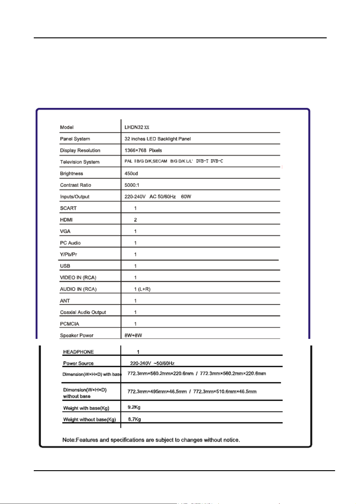
2. Product Specifications:
2.1 Specification:
LHDN32K15/16CEU:
- 10 -
Page 11
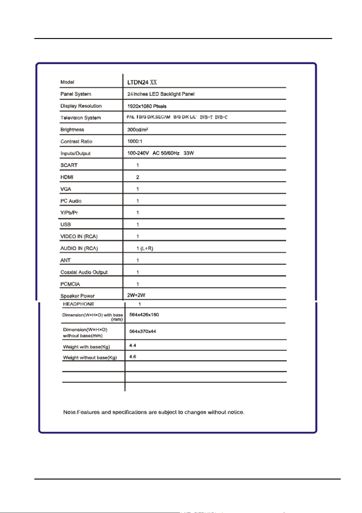
LTDN24K15CEU:
- 11 -
Page 12
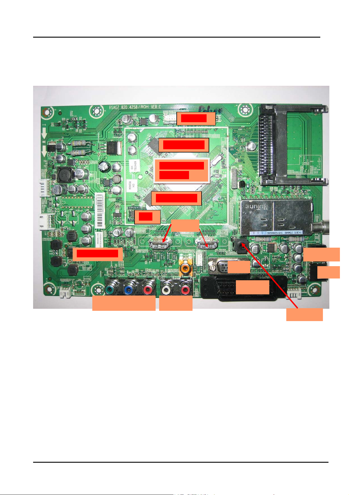
2.2 Main Board:
K15 Series
LVDS OUT
DDR2(512M)
Main IC
(MSD308)
DDR2(512M)
Flash
HDMI
Digital Audio AMP
VGA
SCART
Y/Video PB PR L R
PC Audio IN
Note
actual units to determine the boards.
:
The above “Main board image”is only take LHDN32K15CEU for example, others please refer to the
Earphone
USB
- 12 -
Page 13
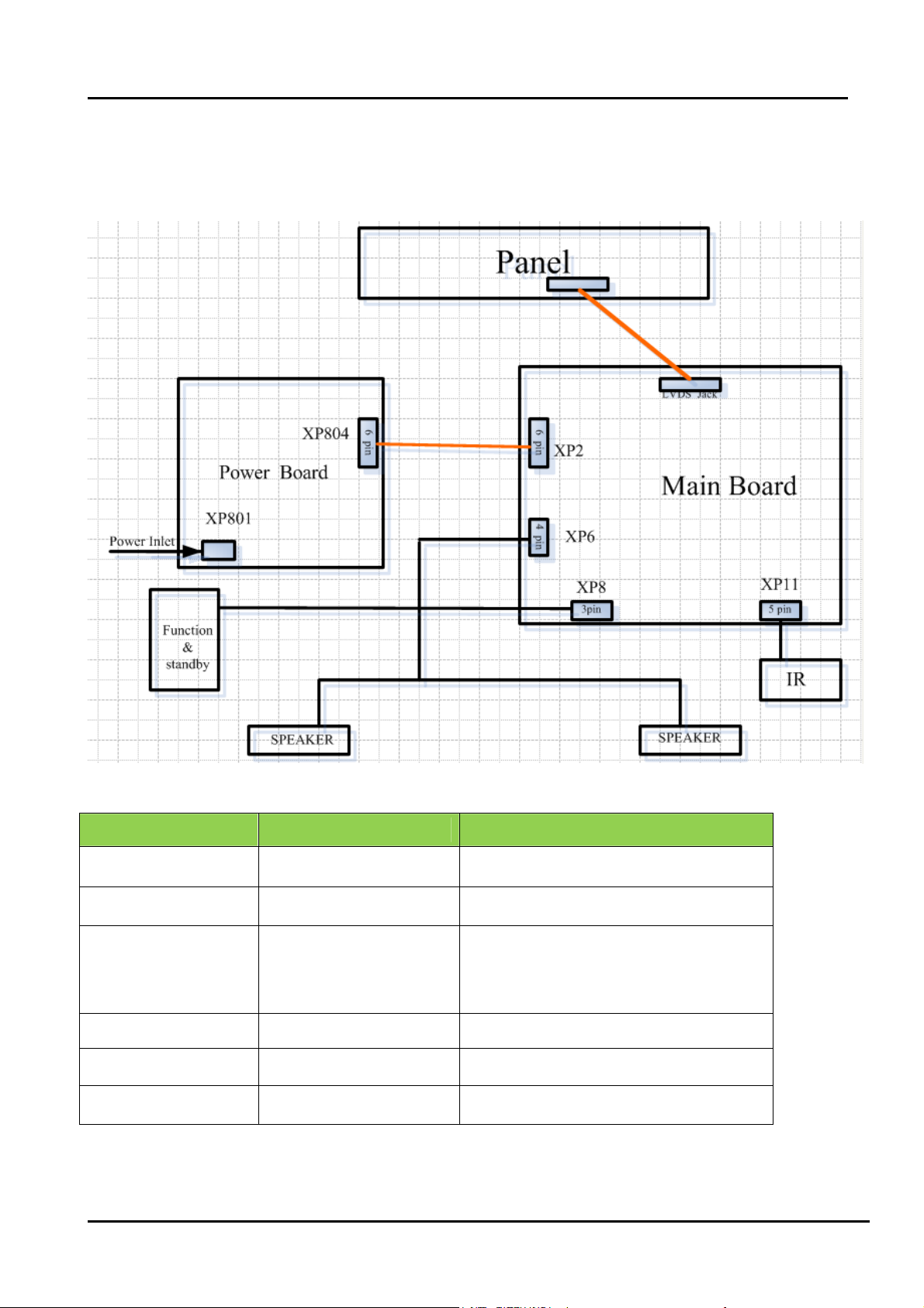
2.3 Wiring Diagram:
LHDN 32K15CEU’’
Model Panel Mode LVDS(Main-Panel)
LTDN24K15CEU M236H3-LA2\V236H1-LE2 HX2-2X20KLB400P-CMO\ROH
LHDN32K15/K16CEU HE315DH-E02(S3)\ROH HX2-2×15KLB400P-HS-1\ROH
LHDN32K15CEU(1) HE315DH-E06\S3\ROH Same to LHDN32K15
- 13 -
Page 14

3. Factory/Service OSD Menu and Adjustment
3.1 To enter the Factory OSD Menu
a. With factory RC (remote control)
1. Press “M” button and enter factory mode.(Note1)
2. Press “Menu” button and enter factory OSD menu.
3. Press “CH+”/“CH-” button select the function menu, press “VOL+”/“VOL-” enter the selected
function menu. Press “VOL+”/“VOL-” button adjust values in the menu.
4. Press “M” button exit factory mode in the factory OSD menu.
When TV outgoing factory, user can not enter factory OSD menu with Factory Remote
Note:
1. In the “Factory Menu”, item “Function”->”TOFAC” ,you can select “M” or “U”, default is “U”.
----M-Means you can enter factory mode with factory RC or user RC.
----U-Means you can enter factory mode only with user’s RC.
2. Mode “M” is only used for factory production.
b. With user’s RC
Power on the TV.
1. Press “Menu” button and call up User OSD Menu.
2. Select “ Sound” -> “Balance” item.
3. Press number key 1->9->6 ->9 in sequence when “Balance” item is focused.
Note: If necessary, re-do number keys.
4. Factory OSD appears.
Note: Press the standby button then AC turn off and restart the TV, which can exit factory OSD menu.
3.2 Factory OSD Menu
The Factory OSD Menu comprises Factory Menu and Design Menu .
3.2.1、Factory Menu
- 14 -
Page 15

Factory Menu
White Balance
ADC Calibration
Funtion
Lnit
Test Pattern
Version
Clear protectly
Clear unprotectly
White Balance
R-DRV:
G- DRV:
B- DRV
R-CUT:
G- CUT:
B- CUT:
Color Temp: Medium
Panel Set : B1
Function
TO FAC : M or U
Power Mode Save
Software Update
LOGO: Hisense
OSD language: English
WDT: ON
UART Debug : None
3.2.2、Design Menu
Design Menu
Picture Mode
Audio Mode
Picture Curve
Audio Curve
SSC Adjust
Saving Mode
Overscan
Not Stand
Note:
The above “Factory/Service OSD Menu” are re ference only, please refer to the actua l units
to determine the appearances.
- 15 -
Page 16
4. Software Upgrading
4.1 Upgrading with the ISP_TOOL
4.1.1 Hardware connecting
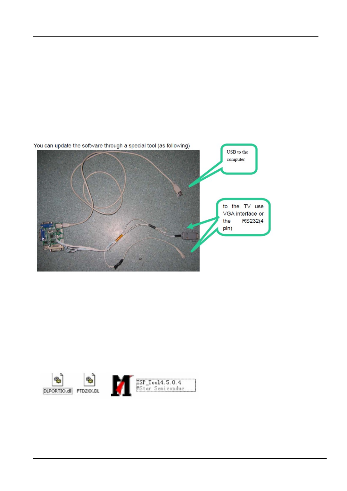
You can update the software through a special tool (as following)
Connect the Debug board to the TV use VGA interface or the RS232 (4 pin), the other USB
port to the compute.
4.1.2 Install the ISP_TOOL4.5.0.4-------only for the first time update.
1、The software is upgraded by a burning tool- ISP_TOOL.exe
2、Find the folder where the ISP_TOOL4.5.0.4 lies in.
There are three folders/files in this folder together.
DLPORTIO.dll and FTD2XX.DLL must be in the same folder
3、Double click the ISP_TOOL4.5.0.4 icon, and then a dialog window will show as below.
- 16 -
Page 17
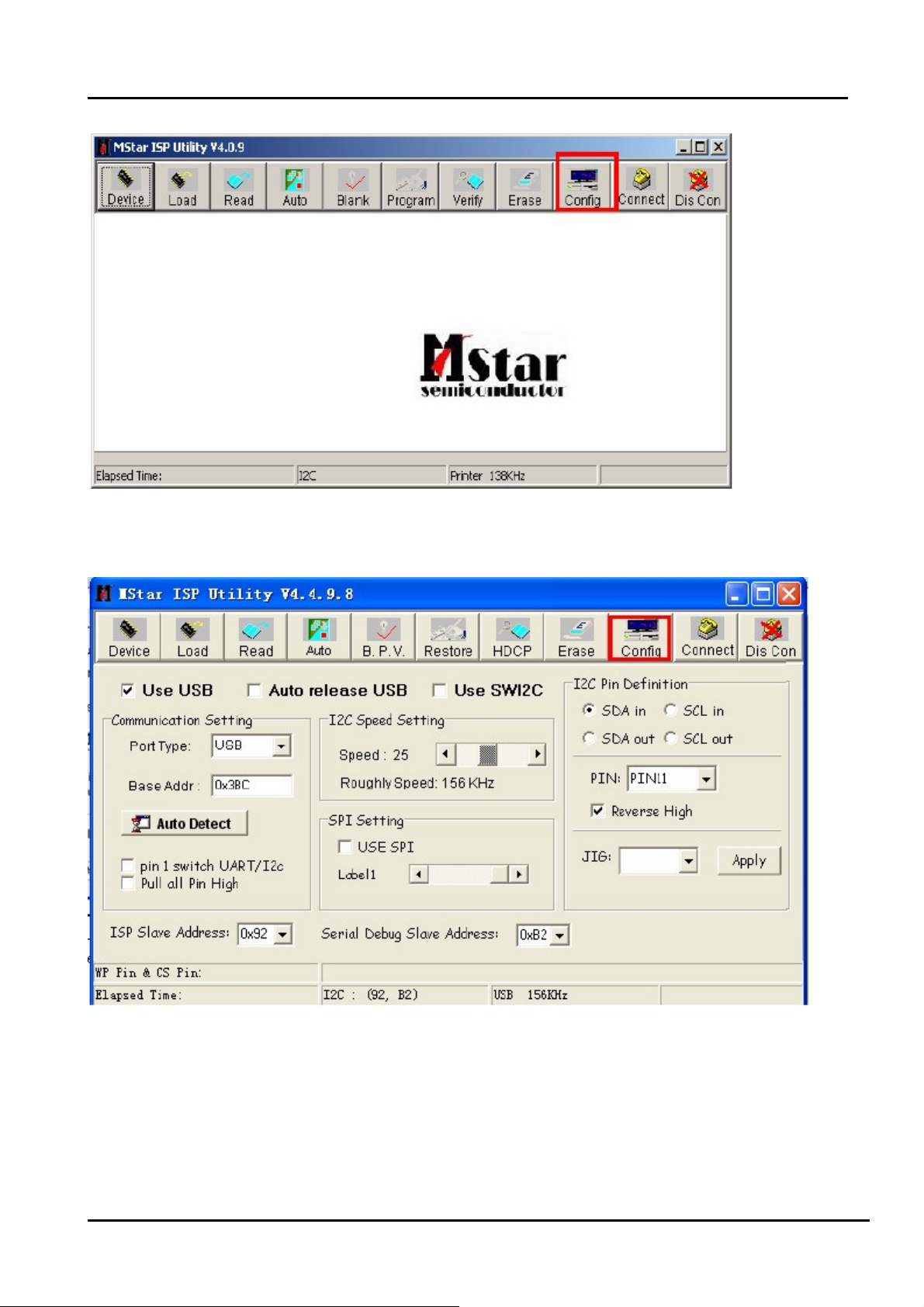
4、Click the” Config “button. And then a dialog window will show as below.
Draw on the front of “Use USB”
Port Type setting is USB
Base Addr setting is 0x38C
ISP Slave Address choose 0x92
Serial Debug Slave Address choose 0xB2,
5、Click the “Connect”button,if appear the following figure, It indicates that the ISP_TOOL has
- 17 -
Page 18

connected.(According to the tv set,”Device Type” maybe different.)
If appear the following figure,It indicates that the ISP_TOOL has not connected. Please click
the“DisCon”button and “Connect”button to connect..
6、Click the“Read ”button,Choose the correct update file。
7、After the update file has been chosen successfully。
Click the“Auto”button and choose parameters as following。
- 18 -
Page 19

8、Click the “Run” button and wait update end.
If show any error message ,then do “Dis Con” >> “Connect”,and click the “Run” button
again,till show the following dialog window。
- 19 -
Page 20

4.2 Upgrading with the USB
Software can update with USB device:
1. Copy the “*.BIN” file such as “MERGE.BIN” to the root directory of a USB disk.
2. Insert the USB disk into the USB slot of the TV SET.
3. Press “Menu” button and call up User OSD Menu,choose "Channel"->”Software
Update(USB)” item. (Note 1)
4. Press “OK”, it will show a confirm message box, Press [◀] button to select “yes” in the
confirm message box, to start automatic update.
5. Then it will update the software automatically,Please don’t power off during the updating
process.
6. After the software is successfully upgraded,TV SET will restart automatically.
Note:
1. In some TV SET, ”Software Update(USB)” item maybe in “OPTION” menu.
2.After updating, you must confirm the software version in the “Factory Menu” and you'd better
do a " UnProtected Clear" in the “Factory Menu”.
- 20 -
Page 21
5. Circuit instruction
5.1 Power assign and block diagram
Power assign:
The Power only has +12V_IN output ,other voltages are converted from +12V_IN.
a. 5Vstb is converted by N19 from +12V_IN,5VAIN and 5V_USB are converted by N43 from 5Vstb.
b. 3.3Vstb and 3.3V_mcu as standby power supply for standby mode.
c. 3.3V_Normal supply power for N5 and Main IC N46 is converted by N3 from 5VAIN; 2.5V_Normal supply
power for N46 is converted by N13 from 5VAIN; VDDC(1.28V) supply power for main IC(core voltage) is
converted by N1 from 5VAIN;1.8VA supply power for N41(DDR),N45(DDR) is converted by N15 from
5VAIN.
e VCC_A supply power for N17(audio amplifier) is converted by N42 from +12V_IN; 5V_Tuner supply
power for Tuner is converted by N16 from +12V; 5V_USB supply power for USB interface.
f VCC-Panel supply power for Panel is converted by N14 from +12V_IN
Block diagram:
+12V
5Vstb
+12V_IN
IRF7314
N42
NB637
N19
STPB2012(L10)
AO4459(N14)
78D05(N16)
IRF7314(N43)
LD1117-3.3
(N2)
VCC _A
VCC-Panel
200mA
5V_Tuner
5VAIN
3.3Vstb
TAS5707(N17)
Panel
FH2610(U42)
380mA
3.3V_mcu
MP1482(N1)
STPB2012
(L46)
5VAIN
FOR STANDBY
FOR STANDBY
1100mA
VDDC
1000mA
5V_USB
500mA
MSD309PX
(N46)
(SH2)
AP1084D-3.3
(N3)
AZ1084S-ADJ
(N15)
LD1117A-2.5
(N13)
3.3V_Normal
1.8VA
2.5V_Normal
(N46,N5)
(N41,N45)
(N46)
- 21 -
Page 22

5.2 Image and signal process
POWER SUPPLY UNIT
SPEAKER(OUT)
HDMI
Amplyfier
HDMI SIGNAL
Panel
LVDS
MSD308PX
TUNER
(FH2610)
DIF
VIF
HS3611
TS
PCMCIA INTERFACE
USB INPUT
AUDIO OUT
REMOTE INFUT SIGNAL
I2C
SCART(CVBS and RGB IN
CVBS OUT,AUDIO IN/OUT)
EARPHONE OUTPUT
REMOTE CONTRAL INPUT
EEPROM
HDCP
DDR
FLASH
HDCP INFO
BUS(DATA,ADDRESS)
BUS(DATA,ADDRESS)
VGA INTERFACE
VIDEO INPUT(YPbPr and
CVBS,AUDIO IN)
a) RF Signal
Digital intermediate frequency and simulation intermediate frequency are processed by Tuner (U42) from RF
Signal. Transport Stream is demodulated directly by main IC from Digital intermediate frequency then enter
PCMCIA card to decipher later return the main IC. The simulation intermediate signal that has passed
amplification and surface acoustic wave filter to get intermediate frequency enters the main IC. After processed
by main IC, next the video signal is processed by SCALER output LVDS signal.to panel . The audio signal is
processed and the Audio amplified to the Speakers.
b). AV Signal
The video signal of AV and YPbPr share the same Terminal of XS13,then enter U46.
- 22 -
Page 23

XS13
左
SIGNAL1
绿
SIGNAL3
中
SIGNAL4
蓝
SIGNAL6
右
SIGNAL7
红
SIGNAL9
GND
GND
GND
1
3
2
4
HD1_Pb
HD1_Pb
6
5
7
HD1_Pr HD1_PrHD1_PrHD1_PrHD1_PrHD1_Pr
9
8
HD1_Y /AV
RV98
ASES12U020R2/NC
RV99
ASES12U020R2/NC
R862
0R
R861
0R
R860
RV105
0R
ASES12U020R2/NC
R345
C214
75R
560p/50V/NC
C207
560p/50V/NC
The CVBS video signal of SCART input the Terminal of XS7, then enter U46.
The RGB video signal of SCART input the Terminal of XS7, then enter U46
XS7
GGND
RGND
BLANK
BLANKGN D
SHIELD
AOR
AIR
AOL
AGND
BGND
AIL
SW
CLK
DATA
GND
R/C
VGND
VOUT
V/YIN
1
2
3
4
5
6
7
B
8
9
10
11
G
12
13
14
15
16
17
18
19
20
21
AV_ROUT
AUR_AV1
AV_LOUT
AUL_AV1
SC-B
SC-FS
SC-G
SC-R
SC-FB
AV_out
AV1
SCART_MODE
SCART_FB_SUB
R350
75R
C208
R399
560p/50V/NC
75R
SCART_RGB
SC-G
SC-B
SC-R
RV74
AVLC18S02015
RV87
AVLC18S02015
SC-FB SC_FB
AVLC18S02015
R421
RV73
0R
AVLC18S02015
SC-FS SC_FS
R420
RV79
8.2k
AVLC18S02015
RV64
R485
75R
R479
75R
75R
R509
R511
75R
SC_FB 2
SC_FS 2
Y1+ 2
PB1+ 2
PR1+ 2
R510
75R
- 23 -
Page 24

+
+
SCART_CVBS_in
RV31
AVLC18S02015
Scart Audio
RV36
AVLC18S02015
AUR_AV1
RV37
AVLC18S02015
R254
AUL_AV1
10k
c) VGA Signal
PC(VGA)signal input from XS24 , later enter U46 .
R863
0R/NC
C336
220p/50V/NC
AV1_AUL
R255
12k
R259
AV1_AUR
10k
R236
12k
CVBS0AV1AV1
R504
C339
220p/50V/NC
75R
AV1_AUL 2
AV1_AUR 2
CVBS0
2
XS24
17 16
DDC_SCL
UART-R
VGA_BIN+
VGA_GIN+
VGA_RIN+
6
11
1
7
12
2
8
13
3
9
14
4
10
15
5
R218
100R
R533
0R/NC
UART-T
VGA_RIN+
DDCSDA
VGA_GIN+
VGA_HS
VGA_BIN+
VGA5V
VGA_VS
UART-R
DDCSCL
RV117
AVLC18S02015
UART-RX 2
AVLC18S02015
RV75
RV76
AVLC18S02015
R235
75R
R493
75R
VGA_BIN+
VGA_GIN
VGA_RIN
R528
75R
- 24 -
Page 25

d) The HDMI and USB signals directly input U46.
e) SCART CVBS output from U46 pass through the following amplified circuit .output from XS7
SCART_CVBS_out
5VAIN
AV_OUTAV_OUTAV_OUT AV_OUTAV_OUT
RV51
AVLC18S02015
L9
R208
BLM18PG181SN1
0R/NC
C830
330u/6V
C199
560p/50V/NC
C194
MMBT3906LT1
100n/25V
R204
75R/NC
2
3
V18
1
R243
150R
R260
150R
R246
330R
V19
3
1
MMBT3904LT1
2
R241
150R
f) Audio Signal (except HDMI and USB)
VGA audio input through XS6, AV and YPbPr Audio input share the same terminal XS14
XS14
白
红
SIGNAL1
SIGNAL3
GND
SIGNAL4
SIGNAL6
GND
1
3
2
4
6
5
HD1/AV-L
R406
10k
RV103
ASES12U020R2/NC
R316
12k
RV104
C209
560p/50V
ASES12U020R2/NC
R336
10k
R256
47k
C831
100u/16V
R226
33k
R361
12k
CVBSOut
C210
560p/50V
CVBSOUT 2
HD2_AUL
HD2_AURHD1/AV-R
HD2_AUL 2
HD2_AUR 2
Audio output
After audio signal was processed by the main IC, outputting digital audio signal that enter I2S and TAS5707
to amplify processing ,finally output to Speakers or soundbars
.
g) Control Process:
The Power only has 12V(+12V_IN) output ,other voltages are converted from 12V(+12V_IN). N43 and
N42 can interrupt other voltages while standby, only reserve standby 5V(5Vstb) and standby 12V(+12V_IN). as
following. When TV Power on , PWR-ON/OFF Signal is Low level, 5VAIN Power supply normally ; otherwise
when TV standby , N43 is shut off , 5VAIN Power _supply is low.
+12V standby signal control as similar as 5VAIN
- 25 -
Page 26

5Vstb
PWR-ON
+12V_IN
1
+12V_IN
5Vstb2
R713
4.7k
PWR-ON
C803
10u/16V
R724
4.7k
1
C801
10u/25V
C713
100n/16V
V710
3
MMBT3904LT1
2
V712
1
5Vstb
R720
10k
C712
100n/25V
R722
3
MMBT3904LT1
2
22k
R758
22k
R723
22k
C715
1u/16V
N43
1
2
3
IRF7314AO4801/3
C718
1u/25V
N42
1
2
3
IRF7314AO4801/3
3.3v_mcu
S1
D11
G1
D12
S2
D21
G24D22
S1
D11
G1
D12
S2
D21
G24D22
8
7
6
5
+12V
8
7
6
5
5VAIN
5VAIN 1
C804
100u/16V
L10
FB1206
1 2
C802
100u/25V
VCC-A
VCC-A 1
100u/25V
C805
+12V 1
H:Disable
R44
10k
L:Enable(default)
PWR-ON/OFF
PWR-ON/OFF 2
PWR-ON
R10
100R
R7
4.7k
V4
3
1
MMBT 3904LT1
2
R41
R40
0R/NC
10k
C714
100n/16V
Power on, the Panel _Backlight and Brightness are control by the main board . the PIN 4 of XP2 is
BL_ON/OFF, the high or low level control the BL_ON/OFF; the PIN 3 of XP2 is BL_ brightness Adjust,
through control the level high or low to control the BL_ brightness.
Back light Control
5VAIN
+12V_IN2
R57
4.7k
V45
3
MMBT3904LT1
2
R63
0R
BRI-EXT
R37
R145
1k
10k/NC
BL-ON/OFF
BRI-EXT 9
BL-ADJUST
C77
10u/10V
BL-ADJUST 9
V46
3
2
R330
4.7k/NC
R78
R64
4.7k
R99
0R/NC
4.7k
1
R143
0R/NC
R334
ON_PBACK2
ADJ-PWM22
ON_PBACK
ADJ-PWM2
1
MMBT3904LT1
10k
R333
4.7k
V44
3
MMBT3904LT1
2
1
+12V_IN
STB2
BL-ADJUST
Inverter
C78
Connector
1n/50V
STB
XP2
7
6
5
4
3
2
1
- 26 -
Page 27

I2C master. for example :search channels , save the customer setting.and the operation of IR and Keypad.
Also can receive information from the EEPROM (N5 AT24C32N)
EEPROM
1
2
3
4
h) The main control signal, as list:
Control Signal
N5
A0
A1
A2
GND
VCC
WP
SCL
SDA
AT24C32N-10SI-2.7
8
7
6
5
net name
Address:0xA0
0:W rit e Enable
1:W rit e D is a ble
33V_Normal
R173
4.7k
100R
R164
I2C-SCL
I2C-SDA 4,9,11,7
4,9,11,7
R157
R175
100R
47R
47R
EEP_VCC
C151
100n/25V
R176
R161
C177
10u/16V
4.7k
WP_EE
I2C-SCL
I2C-SDA
R162
4.7k
recommend Remark
Standby signal(Power
control)
PWR-ON/OFF
Low level power on
PWR-ON/OFF pass V4、
inverse phase
PWR-ON High level power on
BL-control
ON_PBACK High level power on
BL-ON/OFF Low level power on
Audio amplify mute MUTE_5707 Low level mute
Backlight contral
ADJ-PWM2
Contral brightness of
Key “0” KEYPAD-KEY0 Key
Key “1” KEYPAD-KEY1 Key
Remote control signal IR_IN IR
backlight
- 27 -
Page 28

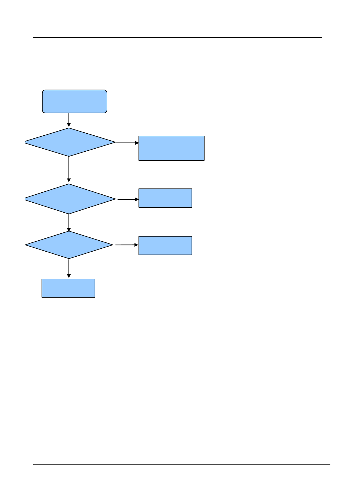
5.3 Troubleshooting
5.3.1 Troubleshooting for Remote Control
Remote control does not work
Try new batteries
NO
Replace RC
Check IR receiver
YES
YES
Replace battery
Replace remote control
Change Led & IR board
NO
Change Led & IR cable
NO
Replace main board
YES
Replace Led & IR BD
YES
Replace Led & IR cable
- 28 -
Page 29

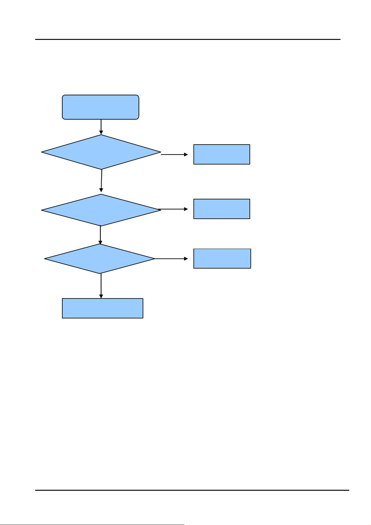
5.3.2 Troubleshooting for Function Key
Buttons does not work
Check switches
YES
Check solder connections and
see if any switches are stuck.
NO
Check key board
NO
Check Key BD cable
YES
Replace Key BD
YES
Change Key BD
OK
NO
Replace main board
- 29 -
Page 30

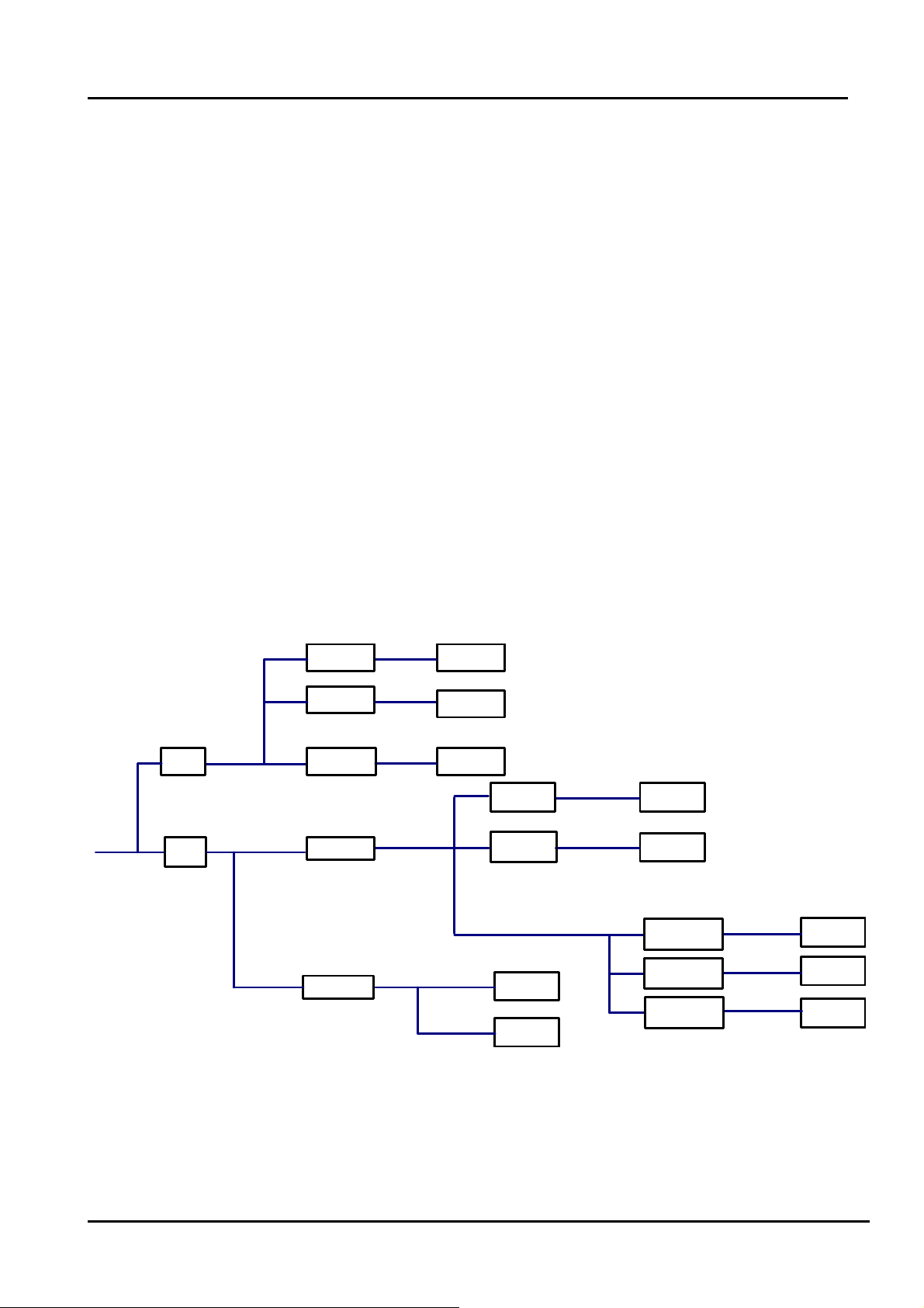
5.3.3 TV won’t Power On
TV won’t power on
Is LED
light?
NO
Check Power
Output
YES
Make Sure Power
source is live
YES
NO
BLUE
RED
Panel Bright
NO
YES
Check signal
Source
YES
NO
Check Power
Cord
NO
Try Power on by
RC and Button
Neither
works
Replace Main
BD
YES
Only
one works
Both
Work
Replace
Power Cord
Check/replace IR
BD or Keypad
PCA
NO
(to contact Hisense tech support.)
Replace Main BD
Replace Panel
OK
YES
Power on
NO
Replace Power BD
YES
OK
- 30 -
Page 31

5.3.4 Troubleshooting for Audio
No sound
Check connecter
YES
Reconnect
NO
Check speaker wire
NO
Check speaker set
YES
YES
Replace speaker wire
Replace speaker set
NO
Replace main board
NO
YES
OK
Power Supply Board
- 31 -
Page 32
5.3.5 Troubleshooting for TV/VGA/HDMI input
No picture on the screen
NO
Check Signal Source
Make sure signal
source is available
YES
Check connect
NO
YES
Check cab l e
NO
Replace main board
Reconnect
Replace cable
- 32 -
Page 33

5.3.6 Troubleshooting for YPbPr input
No picture on the screen
Check Source work or not
YES
Check connect
NO
Check Wires (Green Blue, Red)
NO
Replace main board
NO
YES
YES
Check Source Device
Reconnect
Replace wires
- 33 -
Page 34
5.3.7 Troubleshooting for Video input
No picture on the screen
Check Source work or not
YES
Check connect
NO
Check Cable/ Wires
NO
Replace main board
NO
YES
YES
Check Signal Source
Reconnect
Replace Cable/Wires
- 34 -
Page 35

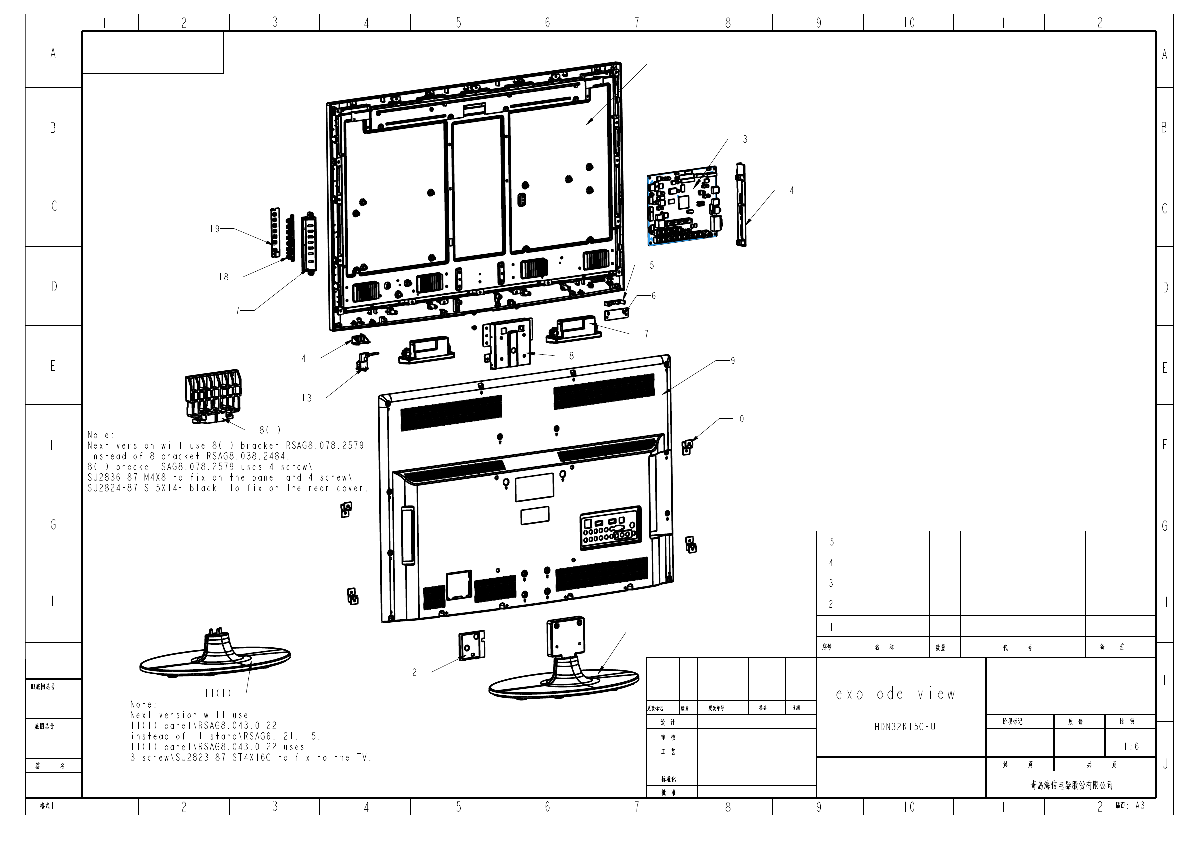
6. Explode View
7. Schematic circuit diagram
- 35 -
Page 36

Page 37

LTDN24K15CEU
2
Led Lens
1
RSAG8.640.0213\ROH
t
11
Bracket
1
RSAG8.078.932\ROH\X0
22
Label
1
RSAG8.804.4247\ROH
No. Description Qty. Code Number Remark
1 Front bezel 1 RSAG8.074.896\FB2\V0\ROH\X0
IR Board
3
1 RSAG2.908.4193-03\ROH
4 Bracket 1 RSAG8.038.2452\ROH
LCD Panel
5
6
Power Board
1 M236H3-LA2\V236H1-LE2\GS\JK\ROH
1 RSAG2.908.2256-52\ROH
7 Bracket 1 RSAG8.078.937\ROH\X0
Keypad PCA (wi
8
1 RSAG2.908.1962\ROH
9 Bracket 1 RSAG8.078.938\ROH\X1
10
Screw
4 SJ2825-87 ST3X12C黑色\ROH\STD
12
13
Power Switch
Power Cord
1 HF-606(TV)-P通PS8-12-D-047B\ROH
1 YS-3-8E-2\ROH
(13-1) STAND 1 RSAG6.121.0224\FB2\ROH\X1\SKD
14 Bracket 1 RSAG8.078.946\ROH\X0
15 Bracket 1 RSAG8.600.171\ROH\X0
16 Bracket 1 RSAG8.038.2486\ROH
17
18
19
20
21
23
24
Bottom Label
Side Label
Rating Label
Bracket Unit
Rear Cover
Bracket Unit
Main Board
1 RSAG8.804.4251\ROH
1 RSAG8.804.4250\ROH
See the TV Rear Back.Difference
1
because of Brands
2 RSAG6.150.804\ROH
1 RSAG8.074.1095\B2\V0\ROH\X0
1 RSAG6.150.1052\ROH
1 RSAG2.908.4258-01\ROH
Page 38

25 Bracket 1 RSAG8.038.2453\ROH
26 Bracket 2 RSAG8.038.2485\ROH
Page 39
1
2
3
4
5
6
7
8
9
10
11
12
A
1
B
3
4
C
19
5
18
D
6
17
7
A
B
C
D
E
14
13
Note:
F
Next version will use 8(1) bracket RSAG8.078.2579
instead of 8 bracket RSAG8.038.2484.
8(1) bracket SAG8.078.2579 uses 4 screw \
SJ2836-87 M4X8 to fix on the panel and 4 screw \
SJ2824-87 ST5X14F black to fix on the rear cover.
8(1)
G
H
8
9
E
10
F
G
5
4
3
H
11
2
1
ÐòºÅ
Ãû ³Æ
ÊýÁ¿
´ú ºÅ
±¸ ×¢
¾Éµ×ͼ×ܺÅ
µ×ͼ×ܺÅ
Ç© Ãû
¸ñʽ1
12
I
11(1)
Note:
Next version will use
11(1) panel \RSAG8.043.0122
instead of 11 stand \RSAG6.121.115.
11(1) panel \RSAG8.043.0122 uses
3 screw\SJ2823-87 ST4X16C to fix to the TV.
1
2
3
4
5
6
¸ü¸Ä±ê¼Ç
Éè ¼Æ
Éó ºË
¹¤ ÒÕ
±ê×¼»¯
Åú ×¼
7
ÊýÁ¿
¸ü¸Äµ¥ºÅ
8
Ç©Ãû
ÈÕÆÚ
explode view
LHDN32K15CEU
9
10
½×¶Î±ê¼Ç
µÚ Ò³
ÖÊ Á¿
¹² Ò³
±È Àý
1:6
Заµºº£РЕµзЖч¹Й·ЭУРПЮ¹«Л¾
·ùÃæ: A3
11
12
J
Page 40

LHDN32K15CEU Parts List
7
VIT3010 8W8Ω 01
Speaker
2
fix with 4 screw\RSAG8.912.018
No. Code Number
Description
1 HE315DH-E02 LED panel 1
2
3 RSAG2.908.4258
4 RSAG8.081.1039
main board
Terminal
Bracket
5 RSAG8.640.0203 lens 1
6 RSAG2.908.2310-52 IR Board 1
-
-
8 RSAG8.038.2484 bracket 1
QTY Note
Front bezel is fixed with panel.
fix with 3 screw\SJ2836-87 M3X8 white and 1 screw\SJ2831-87 ST3X8.
1
1
fix with 2 screw\SJ2825-87 ST3X10C black.
.
fix to panel with 2 screw\GB/T818-2000 M4X6 white and 2
screw\SJ2836-87 M4X6,
fix to front bezel with 2 screw\SJ2824-87 ST4X14F black.
9 RSAG8.074.917 Rear Cover 1
10 RSAG6.150.685 bracket 4
11 RSAG6.121.115 stand 1
12 RSAG8.078.2589 bracket 1
fix to front bezel with 14 screw\SJ2824-87 ST4X14F black.
fix with 4 screw\SJ2824-87 ST4X10F black.
fix with 4 screw\SJ2824-87 ST5X14F black.
fix with 2 screw\SJ2830-87 M3X6 black.
Page 41

13
16
18RSAG8.078.93
b
1
fix to panel with 4 screw\SJ2836 87 M4X8 white,fix to Rear Cover
HF-606(TV)-P通PS8-12-D047B
Power Switch 1
14 RSAG8.078.820 bracket 1
15
16
17 RSAG8.078.938 bracket 1
7
racket
19 RSAG2.908.1962 Keypad PCA 1
8(1) RSAG8.078.2579\ROH bracket 1
11
(1)
RSAG8.043.0122\SKD\ROH stand 1
fix to front bezel with screw\SJ2822-87 ST3X10C black.
fix with 2 screw\SJ2836-87 M3X8 white.
fix to panel with 4 screw\SJ2836-87 M4X8 white,fix to Rear Cover
with 4 screw\SJ2824-87 ST5X14F black. (next version uses Bracket
8(1))
fix to TV with 3 screw\SJ2824-87 ST4X16C black. (next version uses
Stand 11(1))
1102433
152661
Page 42

5
D D
+12V
+12V0
5VAIN0
C C
5VAIN
L18
L18
STPB2012-121PT
STPB2012-121PT
L19
L19
STPB2012-121PT/NC
STPB2012-121PT/NC
C810
C810
100u/16V
100u/16V
R448
R448
100k
100k
C301
C301
100n/16V
100n/16V
1
2
3
4
N1
BS
IN
SW
GND
MP1482N1MP1482
待机12伏和待机5伏在00页中转为主12V和主5伏后返回。
Vout=0.923*(1+4.02K/10K)=1.294 V
N13
2.5V Power
5VAIN
B B
C31
C31
10u/10V
10u/10V
N13
3
LD1117A-2.5AZ1117H-2.5
LD1117A-2.5AZ1117H-2.5
C79
C79
100n/16V
100n/16V
VIN
VOUT
VOUT
ADJ
1
4
2
C74
C74
10u/10V
10u/10V
2.5V_Normal
C80
C80
100n/16V
100n/16V
SOT-223
3.3V Power_Standby
5Vstb
5VAIN
N2
L93
L93
L92
L92
BLM18PG121SN1/NC
BLM18PG121SN1/NC
BLM18PG121SN1/NC
A A
BLM18PG121SN1/NC
C8
10u/10VC810u/10V
N2
3
VIN
C10
C10
100n/16V
100n/16V
5
VOUT
VOUT
ADJ
1
LD1117A-3.3AZ1117H-3.3
LD1117A-3.3AZ1117H-3.3
SOT-223
4
2
L91
L91
BLM18PG121SN1/NC
BLM18PG121SN1/NC
3.3Vstb
3.3Vstb 1
C9
C7
C7
10u/10VC910u/10V
100n/16V
100n/16V
3.3v_mcu 15Vstb 0
4
Vout=0.8*(1+5.1K/0.953K)=5.08 V
L11
L11
10.0 uH
10.0 uH
C300
C300
10n/50V
10n/50V
C305
C305
100n/16V
100n/16V
COMP
8
SS
7
EN
6
3.3n/50V
3.3n/50V
5
C304
FB
C304
R446
R446
2.2k
2.2k
此为待机12V转待机5伏
VDDC
C302
C302
R445
R445
100n/16V
100n/16V
4.02k
4.02k
R428
R428
R447
R447
10k/NC
10k/NC
10k
10k
3.3V Power_Normal
5VAIN 33V_Normal
C13
C13
10u/10V
10u/10V
33V_Normal
N3
N3
2
C12
C12
100n/16V
100n/16V
SOT-252
Vout
Vin
ADJ
1
AP1084D33GAZ1084D-3.3
AP1084D33GAZ1084D-3.3
33V_Normal 1
3
C108
C108
2.2u/10V
2.2u/10V
Power for PCMCIA
L34
L34
STPB2012-121PT/NC
STPB2012-121PT/NC
2
R30
R30
C43
C43
22k
22k
680n/16V
680n/16V
V22
V22
3
MMBT3904LT1
MMBT3904LT1
1
R32
2
4
R32
10k/NC
10k/NC
V27
V27
R341kR34
1k
1
VCC-PCMCIA5VAIN
3
AO3401L
AO3401L
PCM_PWR_CTL 2
R38
R38
1k/NC
1k/NC
C379
C379
100n/16V
100n/16V
3
C303
C303
10u/10V
10u/10V
C14
C14
100n/16V
100n/16V
3
C811
C811
100u/16V
100u/16V
C813
C813
100u/16V
100u/16V
C814
C814
100u/16V
100u/16V
2
背光控制
R330
V46
V46
3
1
2
C956
C956
100u/25V
100u/25V
R453
R453
1
0R/NC
0R/NC
N15
N15
VOUT4VIN
2
VOUT
2
R330
4.7k/NC
4.7k/NC
R78
R78
R64
R64
4.7k
4.7k
R99
R99
0R/NC
0R/NC
4.7k
4.7k
C198
C198
100n/16V
100n/16V
V11
V11
3
MMBT3904LT1
MMBT3904LT1
2
C201
C201
100n/16V
100n/16V
ADJ
1
AZ1084S-ADJ
AZ1084S-ADJ
1
R451
R451
10k
10k
R143
R143
0R/NC
0R/NC
R334
R334
10k
10k
L8
L8
STPB2012-121PT
STPB2012-121PT
L7
L7
STPB2012-121PT
STPB2012-121PT
R454
R454
10k
10k
R450
R450
4.7k
4.7k
MMBT3904LT1
MMBT3904LT1
C812
C812
330u/10V
330u/10V
+12V
5VAIN
ON_PANEL2
ON_PBACK2
ADJ-PWM22
ADJ-PWM2
33V_Normal
1.8V Power for DDR
5VAIN
R460
R460
R464
R464
6.8R/2W
6.8R/2W
6.8R/2W
6.8R/2W
C306
C306
2.2u/10V
2.2u/10V
C310
C310
100n/16V
100n/16V
Vout=Vrefx(1+(R384/R461))+50mAx1
1
+12V_IN
V44
V44
3
MMBT3904LT1
MMBT3904LT1
2
1
R342
R342
47k
47k
R449
R449
4.7k
4.7k
3
2.4k
2.4k
R333
R333
4.7k
4.7k
R461
R461
V45
V45
5VAIN
1
R57
R57
4.7k
4.7k
R630RR63
0R
BRI-EXTON_PBACK
R371kR37
3
R145
R145
1k
10k/NC
10k/NC
MMBT3904LT1
MMBT3904LT1
2
N14
N14
AO4459
AO4459
1
S1
2
S2
3
S3
4
C195
C195
G
1u/16V
1u/16V
R470
R470
R452
R452
100k
100k
4.7k
4.7k
V10
V10
3
MMBT3904LT1
MMBT3904LT1
2
R3841kR384
BL-ON/OFF
BRI-EXT 9
BL-ADJUST
D1
D1
D2
D2
C816
C816
100u/16V
100u/16V
+12V_IN2
C77
C77
10u/10V
10u/10V
VCC-Panel
8
7
6
5
C815
C815
100u/16V
100u/16V
BL-ADJUST 9
C78
C78
1n/50V
1n/50V
1.8VA
C311
C311
100n/16V
100n/16V
STB
STB2
BL-ADJUST
Inverter
Connector
1k
Title
Title
Title
MSD309PX
MSD309PX
MSD309PX
Size Document Number Rev
Size Document Number Rev
Size Document Number Rev
B
B
B
Date: Sheet of
Date: Sheet of
Date: Sheet of
System Power
System Power
System Power
Saturday, November 27, 2010
Saturday, November 27, 2010
Saturday, November 27, 2010
110
110
110
1
XP2XP2
7
6
5
4
3
2
1
A
A
A
Page 43

5Vstb
5Vstb2
PWR-ON
+12V_IN1
+12V_IN
C803
C803
10u/16V
10u/16V
V710
V710
R713
R713
1
4.7k
4.7k
C801
C801
10u/25V
10u/25V
R724
R724
PWR-ON
4.7k
4.7k
H:Disable
L:Enable(default)
5Vstb 3.3v_mcu
R10
R10
PWR-ON
100R
100R
C713
C713
100n/16V
100n/16V
3
MMBT3904LT1
MMBT3904LT1
2
V712
V712
1
R7
4.7kR74.7k
V4
3
MMBT3904LT1V4MMBT3904LT1
2
R720
R720
10k
10k
C712
C712
100n/25V
100n/25V
3
MMBT3904LT1
MMBT3904LT1
2
R40
R40
1
10k
10k
C714
C714
100n/16V
100n/16V
R758
R758
N43
N43
C715
C715
22k
22k
1
C718
C718
1u/25V
1u/25V
S1
2
G1
3
S2
G24D22
IRF7314AO4801/3
IRF7314AO4801/3
N42
N42
1
S1
2
G1
3
S2
G24D22
IRF7314AO4801/3
IRF7314AO4801/3
R44
R44
10k
10k
PWR-ON/OFF
D11
D12
D21
D11
D12
D21
8
7
6
5
+12V
8
7
6
5
PWR-ON/OFF 2
5VAIN
5VAIN 1
C804
C804
100u/16V
100u/16V
L10
L10
FB1206
FB1206
1 2
C802
C802
100u/25V
100u/25V
+12V_IN
L23
L23
220u/25V
220u/25V
STPB3216-121PT
STPB3216-121PT
C806
C806
VCC-A
VCC-A 1
100u/25V
100u/25V
C805
C805
+12V 1
N6
C17
C17
10u/10V
10u/10V
3
C15
C15
100n/16V
100n/16V
N6
1
5Vstb
1u/16V
1u/16V
R723
R723
22k
22k
R722
R722
22k
22k
R41
R41
0R/NC
0R/NC
present for MCU
3.3v_mcu
XP17
XP17
3.3v_mcu
R538
R538
R537
R537
NC/0R
IR_IN2
NC/0R
4.7K
4.7K
IR_mcu
23
V56
V56
2N7002
2N7002
1
R539
R539
NC/10K
NC/10K
3.3v_mcu
R767
R767
RST_MCU
R768
IR_mcu
KEYPAD-KEY0
KEYPAD-KEY1
KEYPAD-KEY1
KEYPAD-KEY0
R768
R770
R770
100R
100R
R771
R771
100R
100R
100R
100R
KEYPAD-KEY11
100R
100R
KEYPAD-KEY01
AMP-MUTE2
3.3v_mcu
12
C961100uF/16V+C961100uF/16V
R772
R772
C378
C378
+
R764
R764
R766
R766
4K7
4K7
4.7K
4.7K
1 2
1 2
NC/10K
NC/10K
NC/22K
NC/22K
R773
R773
1 2
10uF/6.3V
10uF/6.3V
1
VCC
14
VSS
10
RST/NMI/SBWTDIO_3
2
P1.0/TACLK/ACLK/AO_4
3
P1.1/TA0/A1_5
4
P1.2/TA1/A2_6
5
P1.3/ADC10CLK/A3/VREF-/VeREF-_1
R-TSOP14N-065-640-HX
R-TSOP14N-065-640-HX
MSP430F2012
MSP430F2012
XIN/P2.6_11
XOUT/P2.7_12
TEST/SBWTCK_13
P1.7/A7/SDI/SDA/TDO/TDI_7
P1.6/TA1/A6/SDO/SCL/TDI/TCLK_8
P1.4/SMCLK/A4/VREF+/VeREF+/TCK_9
P1.5/TA0/A5/SCLK/TMS_10
1
1
TEST
2
2
RST_MCU
3
3
4
4
TJC10-4A
TJC10-4A
Debug Port
Debug Port
C81
C81
12
N55
N55
13
12
11
9
8
6
7
TEST
MCU_SDA
MCU_SCL
LED1
MCU_PWON/OFF
NC/12pF
NC/12pF
Y5
JU-38Y5JU-38
C82
C82
NC/12pF
NC/12pF
1 2
3.3v_mcu
R774
R774
R775
R775
R776
R776
R777
R777
100R
100R
100R
100R
100R
100R
NC/4.7K
NC/4.7K
100R
100R
R778 4.7KR778 4.7K
R779
R779
1 2
PWR-ON/OFF
I2C-SDA 2,4
I2C-SCL 2,4
LED_M
LED_M 2
C333
C333
C337
C337
C376
C376
C373
C373
10u/16V/NC
10u/16V/NC
10u/16V/NC
10u/16V/NC
22u/16V
22u/16V
100n/16V
100n/16V
VOUT4VIN
2
VOUT
ADJ
LD1117A-3.3AZ1117H-3.3
LD1117A-3.3AZ1117H-3.3
SOT-223
C11
C11
10u/10V
10u/10V
3.3v_mcu
5Vstb
C807
C807
220u/25V
220u/25V
C16
C16
100n/16V
100n/16V
C957
C957
C958
C958
22u/6.3V
22u/6.3V
22u/6.3V
22u/6.3V
3.3v_mcu 1
C959
C959
22u/6.3V
22u/6.3V
C372
C372
100n/16V
100n/16V
L22
L22
3.3 uH
3.3 uH
R512
R512
100K
100K
EN/SYNC
C374
C374
100n/16V/NC
100n/16V/NC
PWR-ON/OFF
R966
R966
10k/NC
10k/NC
R960
R960
10R
10R
R431
R431
47k
47k
C382
C382
100n/16V
100n/16V
R432
R432
R430
R430
0R/NC
0R/NC
4.7k
4.7k
1
2
4
5
6
7
1
N19
N19
IN
SW1
SW23GND
SW4
BST
NB637
NB637
5Vstb
V29
V29
3
MMBT3904LT1
MMBT3904LT1
2
15
14
AGND
NC
13
GND
12
VCC_NB637
VCC11SW3
10
AAM
9
PG
R961
R961
PB8EN/SYNC
12.4k
12.4k
5Vstb
R429
R433
R433
47k/NC
47k/NC
R429
10k
10k
R434
R434
R427
R427
V20
V20
3
R412
R412
100R
100R
0R/NC
0R/NC
1
MMBT3904LT1
MMBT3904LT1
2
4.7k
4.7k
R402
R402
10k
10k
R967
R967
80.6K
80.6K
R964
R964
1.6k
1.6k
STB
STB 1
100p/50V
100p/50V
R965
R965
10k
10k
R9622kR962
2k
R1190RR119
C960
C960
0R
R1218 and R1216----AAM
更换
2380为NB637
C383
C383
100n/16V
100n/16V
R963
R963
10R
10R
Page 44

R533
R533
DDC_SCL
0R/NC
0R/NC
R218
R218
UART-R
VGA_BIN+
100R
100R
VGA_GIN+
VGA_RIN+
R527
R527
UART-T
DDC_SDA
100R
100R
DDCSDA
DDCSCL
RV77
RV77
AVLC18S02015
AVLC18S02015
VGA5V
2
1
+5V
XS6XS6
2
R
1
L
5
SW1
4
SW2
3
GND
R534
R534
0R/NC
0R/NC
RV78
RV78
AVLC18S02015
AVLC18S02015
VD40
VD40
BAT54C
BAT54C
3
5VAIN 1
RV81
RV81
AVLC18S02015/NC
AVLC18S02015/NC
R529
R529
R487
R487
100R
100R
100R
100R
1
A0
2
A1
3
A2
Vss4SDA
K24C02
K24C02
AVLC18S02015/NC
AVLC18S02015/NC
UART-TX 2
N18
N18
VCC
SCL
RV82
RV82
VGA-5V
8
7
WP
6
5
R480
R480
10k
10k
RV117
RV117
AVLC18S02015
AVLC18S02015
C237
C237
100n/25V
100n/25V
R502
R502
12k
12k
VGA-5V
DDC_SCL
C239
C239
560p/50V
560p/50V
R496
R496
10k
10k
DDC_SDA
R526
R526
22k/NC
22k/NC
UART-RX 2
RV75
RV75
AVLC18S02015
AVLC18S02015
R523
R523
10k
10k
R482
R482
10k
10k
AVLC18S02015
AVLC18S02015
R478
R478
12k
12k
AVLC18S02015
AVLC18S02015
RV116
RV116
R484
R484
10k
10k
RV76
RV76
MUX_AUR
MUX_AUL
C243
C243
560p/50V
560p/50V
VGA_HS
VGA_VS
DDC_SDA
DDC_SCL
RV80
RV80
AVLC18S02015
AVLC18S02015
MUX_AUR 2
MUX_AUL 2
VGA_BIN+ 2
VGA_GIN+ 2
R235
R235
R493
R493
75R
75R
75R
75R
R481
R481
22k
22k
XS24XS24
17 16
VGA_RIN+ 2
R528
R528
75R
75R
R483
R483
RGB1_VGA-HS
R230
R230
RGB1_VGA-VS
100R
100R
100R
100R
R232
R232
22k
22k
6
UART-T
11
VGA_RIN+
1
7
DDCSDA
12
VGA_GIN+
2
8
VGA_HS
13
VGA_BIN+
3
VGA5V
9
VGA_VS
14
UART-R
4
10
DDCSCL
15
5
HS_RGB 2
VS_RGB 2
VER.C版本的更改
Page 45

HDTV-1 YPbPr INPUT
YPBPR AND AV INPUT INPUT, AUDIO 共用,
更改为立式插座。
XS13
XS13
左
左
1
SIGNAL1
绿
绿
3
SIGNAL3
2
GND
中
中
4
SIGNAL4
蓝
蓝
6
SIGNAL6
5
GND
右
右
7
SIGNAL7
红
红
9
SIGNAL9
8
GND
XS14
XS14
1
SIGNAL1
白
白
3
SIGNAL3
2
GND
4
SIGNAL4
红
红
6
SIGNAL6
5
GND
SPDIF OUT
XS17黄XS17
SIGNAL
黄
SIGNAL_1
GND
HD1_Y/AV
HD1_Pb
HD1_Pr HD1_PrHD1_PrHD1_PrHD1_PrHD1_Pr
HD1/AV-L
HD1/AV-R
SPDIF-OUT SPDIF_OUT
1
3
2
RV112
RV112
ASES12U020R2/NC
ASES12U020R2/NC
RV98
RV98
ASES12U020R2/NC
ASES12U020R2/NC
R406
R406
10k
10k
RV103
RV103
ASES12U020R2/NC
ASES12U020R2/NC
C216
C216
100n/25V
100n/25V
R335
R335
100R
100R
RV99
RV99
ASES12U020R2/NC
ASES12U020R2/NC
R316
R316
12k
12k
R408
R408
100R
100R
C218
C218
33p/50V
33p/50V
RV105
RV105
ASES12U020R2/NC
ASES12U020R2/NC
RV104
RV104
C209
C209
560p/50V
560p/50V
ASES12U020R2/NC
ASES12U020R2/NC
R8620RR862
0R
R8610RR861
0R
R8600RR860
0R
R336
R336
10k
10k
SPDIF_OUT 2
C214
C214
560p/50V/NC
560p/50V/NC
R361
R361
12k
12k
5VAIN
5VAIN 1
R950
R950
V90
V90
4.7k
4.7k
3
C930
C930
1
R951
R951
MMBT3904LT1
MMBT3904LT1
2
0R/NC
0R/NC
Y2+ 2
PB2+ 2
PR2+ 2
CVBS1
R801
R801
220R
220R
2
CVBS1
22u/6.3V
22u/6.3V
5VAIN
R952
R952
V91
V91
3
C931
C931
4.7k
4.7k
1
R953
R953
MMBT3904LT1
MMBT3904LT1
2
22u/6.3V
22u/6.3V
C208
C210
C210
560p/50V
560p/50V
C207
C207
560p/50V/NC
560p/50V/NC
HD2_AUL
HD2_AUR
C208
R350
R350
R399
R399
560p/50V/NC
560p/50V/NC
75R
75R
75R
HD2_AUL 2
HD2_AUR 2
75R
C932
C932
22u/6.3V
22u/6.3V
C933
C933
22u/6.3V
22u/6.3V
R345
R345
75R
75R
0R/NC
0R/NC
R984
R984
4.7k
4.7k
1
R955
R955
0R/NC
0R/NC
1
R957
R957
0R/NC
0R/NC
5VAIN
V92
V92
R986
R986
V93
V93
4.7k
4.7k
R802
R802
220R
220R
3
MMBT3904LT1
MMBT3904LT1
2
R803
R803
220R
220R
5VAIN
3
MMBT3904LT1
MMBT3904LT1
2
R804
R804
220R
220R
Y2+
PB2+
PR2+
Page 46

R735
PH-Lin7
PH-Rin7
PH-Lin
PH-Rin
R735
470R/NC
470R/NC
C707
C707
R7440RR744
R745
R745
0R
VCC-A
2.2k
2.2k
C888
C888
100u/25V
100u/25V
VCC-A 1
C244
C244
100n/25V
100n/25V
C709
C708
C708
R737
R737
1n/50V/NC
1n/50V/NC
22k/NC
22k/NC
SHUTDOWN
C709
2.2u/10V/NC
2.2u/10V/NC
2.2u/10V/NC
2.2u/10V/NC
R736
R736
22k/NC
22k/NC
R734
R734
470R/NC
470R/NC
C706
C706
1n/50V
1n/50V
SHUTDOWN7
24寸用R745,32寸用R744
C891
C891
100u/16V/NC
100u/16V/NC
1
IN1
2
SGND
3
SVRR
4
OUT1
5
PGND
6
OUT2
7
VCC
8
M_SB
9
IN2
GND_1810GND_19
N44 TPA1517N44 TPA1517
GND_17
GND_16
GND_15
GND_14
GND_13
GND_12
GND_11
GND_10
GND
20
19
18
17
16
15
14
13
12
11
R739
R739
22k/NC
22k/NC
R740
R740
22k/NC
22k/NC
C889
C889
220u/25V/NC
220u/25V/NC
C890
C890
220u/25V/NC
220u/25V/NC
AMP-ROUT
AMP-LOUT
R7430RR743
R7420RR742
R7410RR741
R7380RR738
0R
0R
0R
0R
AMP-R+
AMP-RAMP-L-
AMP-L+
AMP-R+9
AMP-R- 9
AMP-L- 9
AMP-L+ 9
Page 47

5
N46D MSD309PX
N46D MSD309PX
PWM
R3411MR341
1M
XTALO
CI_A8
CI_A10
CI_A1
CI_A13
CI_A14
AB25
AB24
E6
D6
J5
G4
B4
AA7
C4
A4
A2
B3
A3
B2
P6
N6
AA23
AA24
G5
AD1
AE2
E5
C2
B1
AD11
AE11
F11
E11
N46B MSD309PX
N46B MSD309PX
W21
U21
U19
AD12
AC12
AD13
Y12
AA11
Y24
Y22
AB22
AA22
AA20
Y21
AA18
AA19
AA16
AA14
AA12
Y15
AA17
AA15
AE14
Y20
AD16
Y13
Y14
AA13
AC14
AB23
AB20
AB14
AA21
Y25
T21
T19
P21
P20
R20
T20
P19
5
PWM
PAD_PWM0
PAD_PWM1
PAD_PWM2
PAD_PWM3
SAR
SAR
PAD_SAR0
PAD_SAR1
PAD_SAR2_POWER_DET__68
PAD_SAR3
SPI
SPI
PAD_GPIO_PM6_BOOT_FLASH_CS__45
PAD_SPI_CZ_BACKUP_FLASH_CS__46
PAD_SPI_CK
PAD_SPI_DI
PAD_SPI_DO
PAD_GPIO_PM8_FLASH_WP__47
UART/I2CS
UART/I2CS
DDCA_CK
DDCA_DA
I2CM
I2CM
PAD_DDCR_CK
PAD_DDCR_DA
IR
IR
PAD_IRIN
XTAL
XTAL
PAD_XTAL_IN
PAD_XTAL_OUT
RESET
RESET
PAD_RESET
USB
USB
PAD_DP_P0
PAD_DM_P0
PAD_DP_P1
PAD_DM_P1
PAD_GND_EFUSE
PAD_TESTPIN
PCMCIA
PCMCIA
PAD_PCM_D[0]_0
PAD_PCM_D[1]_1
PAD_PCM_D[2]_2
PAD_PCM_D[3]_3
PAD_PCM_D[4]_4
PAD_PCM_D[5]_5
PAD_PCM_D[6]_6
PAD_PCM_D[7]_7
PAD_PCM_A[0]_8
PAD_PCM_A[1]_9
PAD_PCM_A[2]_10
PAD_PCM_A[3]_11
PAD_PCM_A[4]_12
PAD_PCM_A[5]_13
PAD_PCM_A[6]_14
PAD_PCM_A[7]_21
PAD_PCM_A[8]_16
PAD_PCM_A[9]_17
PAD_PCM_A[10]_20
PAD_PCM_A[11]_18
PAD_PCM_A[12]_15
PAD_PCM_A[13]_19
PAD_PCM_A[14]_59
PAD_PCM_RESET
PAD_PCM_IRQA_N
PAD_PCM_OE_N
PAD_PCM_IORD_N
PAD_PCM_CE_N
PAD_PCM_WE_N
PAD_PCM_CD_N
PAD_PCM_WAIT_N
PAD_PCM_IOWR_ N_67
PAD-PCM_REG_N_68
PAD_PCM2_CE_N
NAND FLASH
NAND FLASH
PAD_PF_ALE
PAD_PF_AD[15]_70
PAD_PF_CE0Z
PAD_PF_CE1Z
PAD_PF_OEZ
PAD_PF_WEZ
PAD_F_RBZ
5Vstb
RESET
VD2
VD2
BAV99LT1
BAV99LT1
R239
R239
100k
100k
R248
R248
MMBT3906LT1
MMBT3906LT1
132
1
4.7k
4.7k
V6
V6
C122
C122
10u/16V
10u/16V
PADA_OUTP_CH[6]_PAD_R_ODD[7]__1
PADA_OUTN_CH[6]_PAD_R_ODD[6]__0
PADA_OUTP_CH[7]_PAD_R_ODD[5]__3
PADA_OUTN_CH[7]_PAD_R_ODD[4]__2
PADA_OUTP_CH[8]_PAD_R_ODD[3]__5
PADA_OUTN_CH[8]_PAD_R_ODD[2]__4
PADA_OUTP_CH[9]_PAD_R_ODD[1]__9
PADA_OUTN_CH[9]_PAD_R_ODD[0]__8
PADA_OUTP_CH[10]_PAD_G_ODD[7]__7
PADA_OUTN_CH[10]_PAD_G_ODD[6]__6
PADA_OUTP_CH[11]_PAD_G_ODD[5]__11
PADA_OUTN_CH[11]_PAD_G_ODD[4]__10
PADA_OUTP_CH[12]_PAD_G_ODD[3]__13
PADA_OUTN_CH[12]_PAD_G_ODD[2]__12
PADA_OUTP_CH[13]_PAD_G_ODD[1]__15
PADA_OUTN_CH[13]_PAD_G_ODD[0]__14
PADA_OUTP_CH[14]_PAD_B_ODD[7]__17
PADA_OUTN_CH[14]_PAD_B_ODD[6]__16
PADA_OUTP_CH[15]_PAD_B_ODD[5]__19
PADA_OUTN_CH[15]_PAD_B_ODD[4]__18
PADA_OUTP_CH[16]_PAD_B_ODD[3]__21
PADA_OUTN_CH[16]_PAD_B_ODD[2]__20
PADA_OUTP_CH[17]_PAD_B_ODD[1]__23
PADA_OUTN_CH[17]_PAD_B_ODD[0]__22
PAD_TCON2_FE_ANT5V_MONITOR__62
PAD_TCON3_TUNER_RESET__56
PAD_TCON6_PCM_5V_CTL__74
PAD_TCON7_SIDE_AV_DET__73
PAD_GPIO5_ERROR_OUT__66
PAD_GPIO_PM0_5V_HDMI_3__42
PAD_GPIO_PM1_5V_HDMI_1__67
PAD_GPIO_PM4_POWER_ON_OFF__43
PAD_GPIO_PM5_5V_HDMI_2__65
PAD_GPIO_PM11_DSUB_DET__44
PAD_GPIO_PM12_EDID_WP__64
PAD_TGPIO0_RF_AGC_CTRL__48
PAD_TGPIO1_DEMOD_RESET__49
PAD_TGPIO2_TUNER_SCL__50
PAD_TGPIO3_TUNER_SDA__51
2
R2371kR237
3
1k
R193
R193
22k
22k
PWM0
PWM1
ADJ-PWM2
SAR0
SAR1
SC_FS5
D D
5Vstb
C C
B B
SPI_CSN
SPI_SCK
SPI_SDI
SPI_SDO
4.7k
4.7k
UART-RX
UART-TX
I2C-SCL
I2C-SDA
PCM_D0
PCM_D1
PCM_D2
PCM_D3
PCM_D4
PCM_D5
PCM_D6
PCM_D7
PCM_A0
PCM_A1
PCM_A2
PCM_A3
PCM_A4
PCM_A5
PCM_A6
PCM_A7
PCM_A8
PCM_A9
PCM_A10
PCM_A11
PCM_A12
PCM_A13
PCM_A14
PCM_RESET
PCM_IRQA_N
PCM_OE_N
PCM_IORD_N
PCM_CE_N
PCM_WE_N
PCM_CD_N
PCM_WAIT_N
PCM_IOWR_N
PCM_REG_N
R348
R348
R347
R347
4.7k
4.7k
C178
C178
33p/50V
33p/50V
C176
C176
HC-49SM24MHZ
HC-49SM24MHZ
33p/50V
33p/50V
USB0_DP10
USB0_DM10
R505
R505
R506
R506
SPI-CSNI
R507
R507
SPI-SCKI
R508
R508
SPI-SDII
22R
22R
SPI-SDOI
22R
22R
FLASH_WPN
22R
22R
22R
22R
R519
R519
R520
R520
22R
22R
22R
22R
R5210RR521
R5220RR522
0R
0R
IRIN
XTALI
12
Z1
Z1
System-RST
USB0_DP
USB0_DM
R182
R182
R179
R179
R178
R178
R174
R174
R187
R187
22R
22R
R189
R189
22R
22R
R194
R194
22R
22R
R198
R198
22R
22R
22R
22R
R199
R199
22R
22R
R338
R338
22R
22R
R339
R339
22R
22R
R340
R340
R344
R344
22R
22R
R364
R364
22R
22R
R365
R365
22R
22R
R366
R366
22R
22R
R372
R372
22R
22R
R401
R401
22R
22R
R367
R367
22R
22R
R370
R370
22R
22R
R184
R184
22R
22R
R371
R371
22R
22R
R373
R373
22R
22R
R185
R185
22R
22R
22R
22R
R376
R376
22R
22R
R368
R368
22R
22R
CI_IRQA_N
R369
R369
22R
22R
CI_OE_N
R391
R391
CI_IORD_N
R394
R394
22R
22R
22R
22R
R395
R395
22R
22R
R390
R390
22R
22R
R388
R388
22R
22R
22R
22R
22R
22R
22R
22R
IC Configuration Selection
A A
33V_Normal
R467
R467
R465
R465
I2S_OUT_MCK
R466
R466
10k
10k
I2S_OUT_BCK
10k/NC
10k/NC
R468
R468
I2S_OUT_SD
10k
10k
R271
R271
PWM0
10k
10k
R270
R270
PWM1
10k
10k
10k
10k
LVDS
LVDS
GPIO_TCON
GPIO_TCON
PAD_TCON0
PAD_TCON1_SC1_RE1__55
PAD_TCON4
PAD_TCON5_SC1_MUTE__63
PAD_TCON9_COMP_DET__60
PAD_TCON10_HP_DET__57
PAD_TCON11_HP_MUTE__61
PAD_TCON15_SC1_DET__72
GPIO
PAD_GPIO0_NTP_MUTE__69
PAD_GPIO3_PANEL_CTL__40
PAD_GPIO12_AMD_SCL__70
PAD_GPIO13_AMP_SDA__71
GPIO
PAD_GPIO1_AMP_RST__38
PAD_GPIO2_INV_CTL__39
PAD_GPIO4_USB_CTL__41
GPIO_PM
GPIO_PM
TS1
TS1
PAD_TS1_D[0]_25
PAD_TS1_D[1]_26
PAD_TS1_D[2]_27
PAD_TS1_D[3]_28
PAD_TS1_D[4]_29
PAD_TS1_D[5]_30
PAD_TS1_D[6]_31
PAD_TS1_D[7]_32
PAD_TS1_CLK
PAD_TS1_VLD
PAD_TS1_SYNC
TS0
TS0
PAD_TS0_D[0]_36
PAD_TS0_D[1]_37
PAD_TS0_D[2]_38
PAD_TS0_D[3]_39
PAD_TS0_D[4]_40
PAD_TS0_D[5]_41
PAD_TS0_D[6]_42
PAD_TS0_D[7]_43
PAD_TS0_CLK
PAD_TS0_VLD
PAD_TS0_SYNC
FRONT END
FRONT END
PAD_IP
PAD_IM
PAD_QP
PAD_QM
PAD_VIFP
PAD_VIFM
PAD_SIFP
PAD_SIFM
PAD_IFAGC
PAD_RFAGC_TAGC
C313
C313
10u/16V
10u/16V
System-RST
C123
C123
1n/50V
1n/50V
XP5XP5
AC24
AC25
AD24
AD25
AE24
AC23
AE23
AD23
AE22
AC22
AC21
AD22
AC20
AD21
AE20
AD20
AE19
AC19
AC18
AD19
AC17
AD18
AE17
AD17
AA10
T5
AB10
AB7
AA9
V5
AC11
AA8
R6
Y8
Y9
T4
A7
C7
F4
E4
C3
D4
F6
F5
AB8
H5
C5
K4
L5
M6
TS1_D0
Y16
TS1_D1
AD14
TS1_D2
AD15
TS1_D3
AC15
TS1_D4
AC16
TS1_D5
Y17
TS1_D6
AB17
TS1_D7
AB19
TS1_CK
Y18
AE16
AB16
TS_D0
U20
TS_D1
V20
TS_D2
R19
TS_D3
AE13
TS_D4
AC13
TS_D5
Y11
TS_D6
AB11
TS_D7
AB13
TS_CLK
Y19
TS_MOVAL0
Y23
TS_MOSTART0
W20
AA3
AA2
Y3
Y2
AB1
AA1
AB2
AB3
IFAGC
AD3
TAGC
AE3
RF_AGC_SEL
AC4
SIF_SW
AD2
AD4
AE4
Debug port
1
2
3
4
LVB0P
LVB0N
LVB1P
LVB1N
LVB2P
LVB2N
LVBCP
LVBCN
LVB3P
LVB3N
LVB4P
LVB4N
LVA0P
LVA0N
LVA1P
LVA1N
LVA2P
LVA2N
LVACP
LVACN
LVA3P
LVA3N
LVA4P
LVA4N
WP_EE
PCM_PWR_CTL
HP_DET
ON_USB
AMP-MUTE
AMP-RST
ON_PBACK
ON_PANEL
VIF_SW
ANTPWR_ON
LED1
LED2
PWR-ON/OFF
C168
C168
100n/25V
100n/25V
C169
C169
C171
C171
C174
C174
100n/25V
100n/25V
100n/25V
100n/25V
100n/25V
100n/25V
R188
R188
R215
R215
4.7k
4.7k
4.7k
4.7k
UART-RX
UART-TX
HP_DET
ON_USB
AMP-RST 7
RP966
RP966
RP967
RP967
22R
22R
R203
R203
R205
R205
R181
R181
22R
22R
C341
C341
22R
22R
22R
22R
22R
22R
RP968
RP968
20p/50V/NC
20p/50V/NC
RP969
RP969
22R
22R
R167
R167
R166
R166
R165
R165
22R
22R
22R
22R
22R
22R
22R
22R
C312
C312
150p/50V
150p/50V
VIFP 6
VIFM 6
T_SCL
T_SDA
4
VGA_RIN+5
VGA_GIN+5
VGA_BIN+5
7
10
TS_MDI0
TS_MDI1
TS_MDI2
TS_MDI3
TS_MDI4TS_MDI4
TS_MDI5TS_MDI5
TS_MDI6TS_MDI6
TS_MDI7TS_MDI7
TSCLK
TSVALID
TSSTART
TS_MDO0
TS_MDO1
TS_MDO2
TS_MDO3
TS_MDO4
TS_MDO5
TS_MDO6
TS_MDO7
TS_MOCLK
TS_MOVAL
TS_MOSTART
L57
L57
0.0 uH
0.0 uH
R381
R381
R382
R382
2.2k
2.2k
2.2k
2.2k
T_SCL 6
T_SDA 6
5V-IF
4
HS_RGB5
VS_RGB5
PR1+5
Y1+5
PB1+5
SC_FB5
PR2+5
Y2+5
PB2+5
R206
R206
100R
100R
R250
R250
100R
100R
UART-RX 5
UART-TX 5
HDMI1-RX0N4
HDMI1-RX0P4
HDMI1-RX1N4
HDMI1-RX1P4
HDMI1-RX2N4
HDMI1-RX2P4
HDMI1-CLKN4
HDMI1-CLKP4
HDMI1-SCL4
HDMI1-SDA4
HDMI1-HPDIN4
HDMI0-RX0N4
HDMI0-RX0P4
HDMI0-RX1N4
HDMI0-RX1P4
HDMI0-RX2N4
HDMI0-RX2P4
HDMI0-CLKN4
HDMI0-CLKP4
HDMI0-SCL4
HDMI0-SDA4
HDMI0-HPDIN4
HDMI-CEC4
HDMI-CEC4
TS_MDO[7..0]
VGA_RIN+
VGA_GIN+VGA_GIN+
VGA_BIN+
HS_RGB
VS_RGB
PR1+
PB1+
PR2+
PB2+
TS_MDI[7:0]
Y1+
Y2+
IF+
IF-
R619
R619
R615
R615
R909
R909
R911
R911
68R
68R
R612
R612
33R
33R
R613
R613
68R
68R
R6100RR610
33R
33R
68R
68R
33R
33R
0R
R594
R594
R595
R595
R593
R593
R592
R592
68R
68R
R590
R590
33R
33R
R463
R463
68R
68R
R5910RR591
33R
33R
68R
68R
33R
33R
0R
R598
R598
R599
R599
R597
R597
R596
R596
68R
68R
R600
R600
33R
33R
R462
R462
68R
68R
R6010RR601
33R
33R
68R
68R
33R
33R
0R
HDMI1-RX0N
HDMI1-RX0P
HDMI1-RX1N
HDMI1-RX1P
HDMI1-RX2N
HDMI1-RX2P
HDMI1-CLKN
HDMI1-CLKP
HDMI1-SCL
HDMI1-SDA
HDMI1-HPDIN
HDMI0-RX0N
HDMI0-RX0P
HDMI0-RX1N
HDMI0-RX1P
HDMI0-RX2N
HDMI0-RX2P
HDMI0-CLKN
HDMI0-CLKP
HDMI0-SCL
HDMI0-SDA
HDMI0-HPDIN
HDMI-CECHDMI-CEC
PCM_CD1_N
TS_MDO3
TS_MDO4
TS_MDO5
TS_MDO6
TS_MDO7
PCM_IORD_N
PCM_IOWR_N
TSSTART
TS_MDI0
TS_MDI1
TS_MDI2
TS_MDI3
TS_MDI4
TS_MDI5
TS_MDI6
TS_MDI7
TS_MOCLK
6
PCM_RESET
PCM_WAIT_N
PCM_REG_N
TS_MOVAL
TS_MOSTART
TS_MDO0
6
TS_MDO1
TS_MDO2
PCM_CD2_N
AGC
N46E MSD309PX
N46E MSD309PX
C484
C484
RGB CVBS
RGB CVBS
C481
C481
M2
C485
C485
PADA_RIN0M
M3
C483
C483
PADA_RIN0P
L2
PADA_GIN0M
C477
C477
47n/16V
47n/16V
L3
PADA_GIN0P
C480
C480
47n/16V
47n/16V
K1
C478
C478
PADA_BIN0M
47n/16V
47n/16V
K3
PADA_BIN0P
47n/16V
47n/16V
K2
PADA_SOGIN0
47n/16V
47n/16V
N4
PAD_HSYNC0
47n/16V
47n/16V
N5
C479
C479
PAD_VSYNC0
1n/50V
1n/50V
C404
C404
R3
C396
C396
PADA_RIN1M
P2
PADA_RIN1P
C192
C192
P3
PADA_GIN1M
C482
C482
47n/16V
47n/16V
N2
PADA_GIN1P
C190
C190
47n/16V
47n/16V
N3
C403
C403
PADA_BIN1M
47n/16V
47n/16V
M1
PADA_BIN1P
47n/16V
47n/16V
N1
PADA_SOGIN1
47n/16V
47n/16V
W6
PAD_HSYNC1
47n/16V
47n/16V
Y6
PAD_VSYNC1
C440
C440
1n/50V
1n/50V
C402
C402
U2
C395
C395
PADA_RIN2M
U3
PADA_RIN2P
C193
C193
T2
PADA_GIN2M
C476
C476
47n/16V
47n/16V
T1
C191
C191
PADA_GIN2P
47n/16V
47n/16V
R1
C398
C398
PADA_BIN2M
47n/16V
47n/16V
R2
PADA_BIN2P
47n/16V
47n/16V
T3
PADA_SOGIN2
47n/16V
47n/16V
V4
PAD_HSYNC2
47n/16V
47n/16V
1n/50V
1n/50V
N46C MSD309PX
N46C MSD309PX
HDMI AUDIO
HDMI AUDIO
G2
PAD_RX0N_A
H3
PAD_RX0P_A
H2
PAD_RX1N_A
J3
PAD_RX1P_A
J2
PAD_RX2N_A
J1
PAD_RX2P_A
G3
PAD_RXCN_A
G1
PAD_RXCP_A
M4
DDCDA_CK
M5
DDCDA_DA
K6
PAD_HOTPLUGA
D2
PAD_RX0N_B
E3
PAD_RX0P_B
E2
PAD_RX1N_B
F3
PAD_RX1P_B
F2
PAD_RX2N_B
F1
PAD_RX2P_B
D3
PAD_RXCN_B
D1
PAD_RXCP_B
J6
DDCDB_CK
L6
DDCDB_DA
J4
HOTPLUGB
AC8
PAD_RX0N_C
AD9
PAD_RX0P_C
AC9
PAD_RX1N_C
AD10
PAD_RX1P_C
AE10
AC10
AE8
AD8
AE7
AD7
AC7
K5
PAD_RX2N_C
PAD_RX2P_C
PAD_RXCN_C
PAD_RXCP_C
DDCDC_CK
DDCDC_DA
PAD_HOTPLUGC
PAD_CEC
PAD_I2S_IN_BCK_USB_OCD__52
PAD_I2S_IN_WS_WARM_LED_ON__54
PCMCIA
XS31 PCMCIAXS31 PCMCIA
35
GND
GND_34
36
37
38
39
40
41
42
43
44
45
46
47
48
49
50
51
52
53
54
55
56
57
58
59
60
61
62
63
64
65
66
67
68
5V-IF
R6611kR661
R642
R642
IFAGC IF_AGC
1k
5V-IF
10k
10k
R641
R641
R643
R643
TAGC
10k
10k
C471
C471
10k
10k
100n/25V
100n/25V
D3
CD1#_35
D4
MDO3
D5
MDO4
D6
MDO5
D7
MDO6
CE1#_6
MDO7
A10
CE2#_41
OE#_8
VS1#_42
A11
IORD#_43
A9
IOWR#_44
A8
MISTRT
A13
MDI0
A14
MDI1
WE#_14
MDI2
READY
MDI3
VCC
VCC_50
VPP1
VPP2
MIVAL
MDI4
MICLK
MDI5
A12
MDI6
A7
MDI7
A6
MOCLK
A5
RESET
A4
WAIT#_58
A3
INPACK
A2
REG#_60
A1
MOVAL
A0
MOSTART
D0
MDO0
D1
MDO1
D2
MDO2
WP
CD2#_66
GND_33
GND_67
GND_6869GND_6970GND_7071GND_71
72
C460
C460
100n/25V
100n/25V
IF_AGC
C462
C462
22n/25V
22n/25V
RF_AGC
RF_AGC
C491
C491
22n/25V
22n/25V
Close to chip
3
PADA_CVBS0
PADA_CVBS1
PADA_CVBS2
PADA_CVBS3
PADA_CVBS4
PADA_CVBS5
PADA_CVBS_OUT1
PADA_CVBS_OUT2
PADA_VCOM
PAD_LINEIN_L0
PAD_LINEIN_R0
PAD_LINEIN_L1
PAD_LINEIN_R1
PAD_LINEIN_L2
PAD_LINEIN_R2
PAD_LINEIN_L5
PAD_LINEIN_R5
PAD_LINEOUT_L0
PAD_LINEOUT_R0
PAD_LINEOUT_L3
PAD_LINEOUT_R3
PAD_EARPHONE_OUTL
PAD_EARPHONE_OUTR
PAD_VRP
PAD_VAG
AVSS_VRM_ADC_DAC
I2S
I2S
PAD_I2S_OUT_MCK
PAD_I2S_OUT_SD
PAD_I2S_OUT_WS
PAD_I2S_OUT_BCK
PAD_I2S_IN_SD_LED_ON__53
SPDIF
SPDIF
PAD_SPDIF_OUT
VCC-PCMCIAVCC-PCMCIA
1
PCM_D3
2
PCM_D4
3
PCM_D5
4
PCM_D6
5
PCM_D7
6
PCM_CE_N
7
PCM_A10
8
PCM_OE_N
9
PCM_A11
10
PCM_A9
11
PCM_A8
12
PCM_A13
13
PCM_A14
14
PCM_WE_N
15
PCM_IRQA_N
16
17
18
TSVALID
19
TSCLK
20
PCM_A12
21
PCM_A7
22
PCM_A6
23
PCM_A5
24
PCM_A4
25
PCM_A3
26
PCM_A2
27
PCM_A1
28
PCM_A0
29
PCM_D0
30
PCM_D1
31
PCM_D2
32
33
34
Boot Loader SPI Flash
6
6
3
3.3Vstb
SPI_CSN
SPI_SDO
AC5
W4
W5
AA5
W2
W3
CVBSOut
V3
AA4
W1
R611
R611
47R
47R
R4
R5
T6
U6
V6
U5
AD6
AC6
V1
V2
AUOUTL1
AA6
AUOUTR1
Y5
EARPHONE_OUTL
AD5
EARPHONE_OUTR
AE5
AB4
AB5
AC3
A6
B5
I2S_OUT_LRCKI2S_OUT_LRCK
B6
C6
C1
H6
G6
P5
EARPHONE_OUTR
EARPHONE_OUTL
I2S_OUT_MCK
I2S_OUT_SD
I2S_OUT_LRCK
I2S_OUT_BCK
5VAIN
C147
C147
100n/25V
100n/25V
C488
C488
C489
C489
47R
47R
47n/16V
47n/16V
47R
47R
47n/16V
47n/16V
CVBSOUT 5
C490
C490
47n/16V
47n/16V
C102
C102
C116
C116
AUL1
C109
C109
AUR1
C107
C107
AUL2
C104
C104
2.2u/10V
2.2u/10V
AUR2
C103
C103
2.2u/10V
2.2u/10V
AUL5
2.2u/10V
2.2u/10V
AUR5
2.2u/10V
2.2u/10V
2.2u/10V
2.2u/10V
2.2u/10V
2.2u/10V
AUVRP
AUVAG
AUVRM
I2S_OUT_MCK
Close to IC
I2S_OUT_SD
with width
trace
I2S_OUT_BCK
AUOUTR1
AUOUTL1
SPDIF_OUT 5
R3931kR393
R3971kR397
1k
1k
PCM_CD1_N
PCM_CD2_N
N11
N11
NC/MX25L6405
NC/MX25L6405
1
HOLD_0
2
VCC
3
NC1
4
NC2
5
NC3
6
NC4
7
SO16-CS_6
8
DO
M25P32VMNTKH25L3205DM2C-12G
M25P32VMNTKH25L3205DM2C-12G
R907
R907
R908
R908
R670RR67
R660RR66
0R
0R
C331
C331
10u/10V
10u/10V
8
VCC
S
1
LVB0N
LVB0P
LVB1N
LVB1P
LVB2N
LVB2P
LVBCN
LVBCP
LVB3N
LVB3P
LVB4N
LVB4P
LVA0N
LVA0P
LVA1N
LVA1P
LVA2N
LVA2P
LVACN
LVACP
LVA3N
LVA3P
LVA4N
LVA4P
HD2_AUL 5
HD2_AUR 5
MUX_AUL 5
MUX_AUR 5
AV1_AUL 5
AV1_AUR 5
C167
C167
100n/16V
100n/16V
C118
C118
220p/50V
220p/50V
1
2
7
N12
N12
HOLD
Q2VSS4W
CVBS0
CVBS1
22R
22R
22R
22R
22R
22R
22R
22R
22R
22R
22R
22R
C175
C175
100n/16V
100n/16V
R123
R123
220k
220k
EARPHONE_OUTR 7
EARPHONE_OUTL 7
I2S_OUT_MCK 7
I2S_OUT_SD 7
I2S_OUT_LRCK 7
I2S_OUT_BCK 7
3
6
C
3
WP/Vpp_8
CVBS0 5
CVBS1 5
RP965
RP965
RP964
RP964
RP963
RP963
RP962
RP962
RP961
RP961
RP960
RP960
VCC-Panel
VD78
VD78
BAT54C
BAT54C
CLK
DI
5
NC8
D
NC7
NC6
NC5
VSS
R6_RXO0R7_RXO0+
R4_RXO1R5_RXO1+
R2_RXO2R3_RXO2+
R0_RXOCR1_RXOC+
G6_RXO3G7_RXO3+
G4_RXO4G5_RXO4+
G2_RXE0G3_RXE0+
G0_RXE1G1_RXE1+
B6_RXE2B7_RXE2+
B4_RXECB5_RXEC+
B2_RXE3B3_RXE3+
B0_RXE4B1_RXE4+
R678
R678
27k/NC
27k/NC
R694
R694
10k/NC
10k/NC
C330
C330
10u/10V
10u/10V
L20
L20
BLM18PG181SN1
BLM18PG181SN1
AU_ROUT 5
AU_LOUT 5
R127
R127
C117
C117
220p/50V
220p/50V
220k
220k
R659
R659
100R
100R
16
15
14
13
12
11
10
9
R699
R699
0R/NC
0R/NC
PCM_CD_N
R6581kR658
1k
SPI_SCK
SPI_SDI
C148
C148
20p/50V/NC
20p/50V/NC
C146
C146
1n/50V
1n/50V
VCC-Panel
R704
R704
R703
R703
27k/NC
27k/NC
R705
R705
100R
100R
10k
10k
+3.3AVDD +3.3AVDD
AI
IR&KEY PAD
1
2
3
4
5
6
7
8
XP11XP11
N5
N5
1
A0
A12WP
A23SCL
4
GND
AT24C32N-10SI-2.7
AT24C32N-10SI-2.7
R77
R77
FLASH_WPN
33k
33k
2
LVDS CONNECTOR
LVDS_SCL
R140
R140
4.7k/NC
4.7k/NC
GVMODSEL
GVMODSELGVMODSELGVMODSEL
R8420RR842
0R
IR_IN
R138
R138
LED_CTL
LED_EN
100R/NC
100R/NC
VER.B更改遥控控制
IR_IN
RV85
RV85
AVLC18S02015/NC
AVLC18S02015/NC
VCC-Panel
LVDS_SCL
BRI_OUT EXT_BRI
R6_RXO0-
R2_RXO2- R3_RXO2+
R0_RXOCG6_RXO3- G7_RXO3+
G4_RXO4-
G2_RXE0- G3_RXE0+
R141
R141
4.7k/NC
4.7k/NC
G0_RXE1- G1_RXE1+
8/10BITSEL
8/10BITSEL8/10BITSEL8/10BITSEL8/10BITSEL8/10BITSEL8/10BITSEL8/10BITSEL
B6_RXE2B4_RXEC-
R9100RR910
B2_RXE3-
0R
R134
R134
R135
R135
100R/NC
100R/NC
100R/NC
100R/NC
1k
C135
C135
100pF
100pF
5Vstb
R2381kR238
1k
V8
V8
R2511kR251
1
R224
R224
4.7k
4.7k
5Vstb
R275
R275
4.7k
4.7k
EEPROM
8
VCC
7
6
5
SDA
Address:0xA0
HDCP
R130
R130
10k
10k
N4
N4
1
8
A0
VCC
2
7
A1
WP
3
6
A2
SCL
5
Vss4SDA
AT24C04N-10SU-2.7
AT24C04N-10SU-2.7
Address:0xA4
2
IR_IN 0
5Vstb
C134
C134
I2C-SCL
1n/50V
1n/50V
I2C-SDA
3
IRIN
MMBT3904LT1
MMBT3904LT1
2
LED2
0:Write Enable
1:Write Disable
EEP_VCC
R157
R157
R175
R175
R176
R176
100R
100R
47R
47R
47R
47R
EEP_VCC
R124
R124
R128
R128
R129
R129
100R
100R
47R
47R
47R
47R
XP16XP16
12
3
4
5
6
7
8
9
10
11
12
13
14
15
16
17
18
19
20
21
22
23
24
25
26
27
28
29
30
31
32
33
34
35
36
37
38
39
40
VER.B更改KEY0和GND顺序
C139
C139
XP8XP8
C136
C136
20p/50V/NC
20p/50V/NC
20p/50V/NC
20p/50V/NC
3.3v_mcu
R398
R398
R319
R319
4.7k
4.7k
LED_M
4.7k
4.7k
R530
R530
LED_M
0R/NC
0R/NC
R162
R162
R161
R161
C151
C151
C177
C177
100n/25V
100n/25V
10u/16V
10u/16V
4.7k
4.7k
4.7k
4.7k
WP_EE
I2C-SCL
I2C-SDA
R126
R126
C145
C145
100n/25V
100n/25V
4.7k
4.7k
I2C-SCL
I2C-SDA
1
VCC-Panel
C892
C892
100u/25V
100u/25V
AI
GVMODSEL8/10BITSEL
R7_RXO0+
R5_RXO1+R4_RXO1-
R1_RXOC+
G5_RXO4+
AI
3.3v_mcu
R247
R247
2.2k
2.2k
KEYPAD-KEY0
RV3
RV3
AVLC18S02015/NC
AVLC18S02015/NC
5Vstb
R331
R331
V26
V26
10k
10k
3
LED_EN
2
MMBT3904LT1
MMBT3904LT1
33V_Normal
4,9,11,7
I2C-SCL
I2C-SDA 4,9,11,7
MSD309PX
MSD309PX
MSD309PX
MSD309PX-1
MSD309PX-1
MSD309PX-1
Saturday, November 27, 2010
Saturday, November 27, 2010
Saturday, November 27, 2010
LVDS_SCL
EXT_BRI
BRI_OUT
R352
R352
2.2k
2.2k
KEYPAD-KEY1
RV4
RV4
AVLC18S02015/NC
AVLC18S02015/NC
R5240RR524
0R
4.7k
4.7k
33V_Normal
1
R240
R240
B7_RXE2+
B5_RXEC+
B3_RXE3+
B1_RXE4+B0_RXE4-
3
2
1
R192
R192
0R/NC
0R/NC
1
LED_M 0
R5310RR531
0R
LED1
R164
R164
R173
R173
100R
100R
4.7k
4.7k
Title
Title
Title
Size Document Number Rev
Size Document Number Rev
Size Document Number Rev
Custom
Custom
Custom
Date: Sheet of
Date: Sheet of
Date: Sheet of
C640
C640
100n/25V
100n/25V
R702
R702
R700
R700
1k/NC
1k/NC
R675
R675
1k/NC
1k/NC
R701
R701
1k/NC
1k/NC
1k/NC
1k/NC
33V_Normal
5VAIN
KEYPAD-KEY1
KEYPAD-KEY0
3.3v_mcu 0
C170
C170
C160
C160
100n/25V
100n/25V
10u/16V
10u/16V
1k
1k
C156
C156
1n/50V
1n/50V
R354
R354
0R/NC
0R/NC
1
5Vstb
3.3Vstb
PWR-ON/OFF
R21
R21
ON_PANEL
R151
R151
ON_PBACK
R24
R24
ADJ-PWM2
10k
10k
R33
R33
10k
10k
AMP-MUTE
10k
10k
R26
R26
RF_AGC_SEL
R150
R150
10k
10k
VIF_SW
R152
R152
SIF_SW
R153
R153
10k
10k
ANTPWR_ON
10k
10k
R155
R155
10k
10k
ON_USB
10k
10k
10k
10k
R212
R212
PCM_IRQA_N
R221
R221
PCM_WAIT_N
R231
R231
PCM_PWR_CTL
10k
10k
10k
10k
10k
10k
C951
C951
100n/25V
100n/25V
VCC-Panel
I2C-SCL
BL-ADJUST
33V_Normal 1
5VAIN 1
KEYPAD-KEY11
KEYPAD-KEY01
R3561kR356
SAR1
R2761kR276
SAR0
C159
C159
1n/50V
1n/50V
5Vstb
R355
R355
10k
10k
LED_CTL
V9
V9
3
MMBT3904LT1
MMBT3904LT1
2
210
210
210
I2C-SDA 2,4
I2C-SCL 2,4
BRI-EXT 1
BL-ADJUST 1
5Vstb 1
3.3Vstb 1
PWR-ON/OFF 1
ON_PANEL 1
ON_PBACK 1
ADJ-PWM2 1
AMP-MUTE 7
RF_AGC_SEL 6
VIF_SW 6
ANTPWR_ON
ON_USB 1
PCM_PWR_CTL 1
C950
C950
100n/25V
100n/25V
C540
C540
100n/25V
100n/25V
6
A
A
A
Page 48
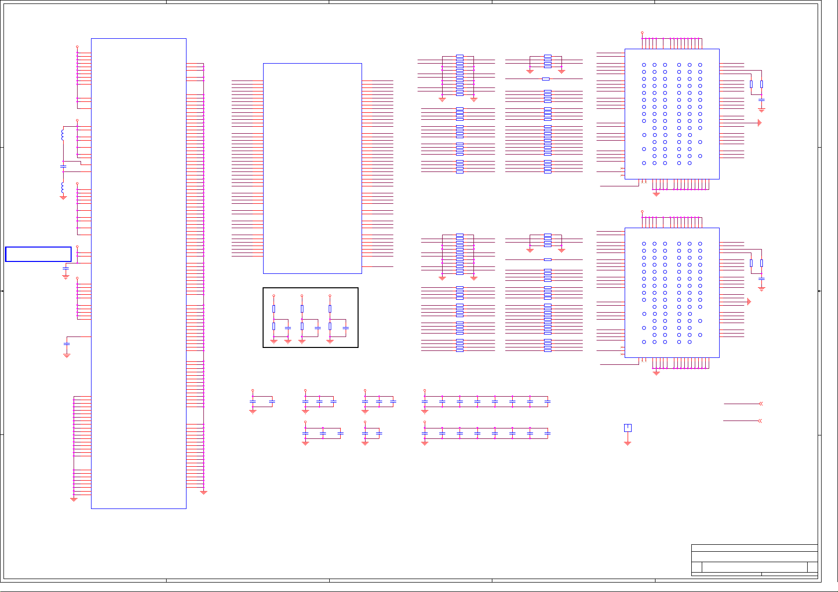
5
4
3
2
1
B3
UDM
F3
LDM
F7
LDQS
E8
LDQS#
B7
UDQS
A8
UDQS#
D3
DQ11
D1
DQ12
C2
DQ9
B1
DQ14
F1
DQ6
G2
DQ1
H3
DQ3
H1
DQ4
L3
BA1
L2
BA0
M3
A1
M2
A10
N3
A5
P3
A9
R2
A12
P2
A7
N2
A3
R7
RFU1
L1
RFU2
R3
RFU3
N45
N45
H5PS5162FFR-25C
H5PS5162FFR-25C
B3
UDM
F3
LDM
F7
LDQS
E8
LDQS#
B7
UDQS
A8
UDQS#
D3
DQ11
D1
DQ12
C2
DQ9
B1
DQ14
F1
DQ6
G2
DQ1
H3
DQ3
H1
DQ4
L3
BA1
L2
BA0
M3
A1
M2
A10
N3
A5
P3
A9
R2
A12
P2
A7
N2
A3
R7
RFU1
L1
RFU2
R3
RFU3
N41
N41
H5PS5162FFR-25C
H5PS5162FFR-25C
SH1
SH1
MARK
MARK
1
1
1.8VA
E9
C9
C7
A9
C1
C3
G1
VDDL
VSS
VDDL
VSS
VDDQ
A
A
B
B
C
C
D
D
E
E
F
F
G
G
H
H
J
J
K
K
L
L
M
M
N
N
P
P
R
R
VSS
P9
A9
VDDQ
A
A
B
B
C
C
D
D
E
E
F
F
G
G
H
H
J
J
K
K
L
L
M
M
N
N
P
P
R
R
VSS
P9
VDDQ
VDDQ
VDDQ
VDDQ
VDDQ
VssQ UDQS# VddQ
VssQ UDQS# VddQ
UDQS VssQ DQ15
UDQS VssQ DQ15
VddQ DQ8 VddQ
VddQ DQ8 VddQ
DQ10 VssQ DQ13
DQ10 VssQ DQ13
VssQ LDQS# VddQ
VssQ LDQS# VddQ
LDQS VssQ DQ7
LDQS VssQ DQ7
VddQ DQ0 VddQ
VddQ DQ0 VddQ
DQ2 VssQ DQ5
DQ2 VssQ DQ5
VssDL CK Vdd
VssDL CK Vdd
RAS# CK# ODT
RAS# CK# ODT
CAS# CS#
CAS# CS#
A2 A0 Vdd
A2 A0 Vdd
A6 A4
A6 A4
A11 A8
A11 A8
RFU NC
RFU NC
VSSQ
VSSQ
VSSQ
VSSQ
VSSQ
B2
A7
B8
D8
D2
E9
C9
C7
C1
C3
VDDQ
VDDQ
VDDQ
VDDQ
VDDQ
VssQ UDQS# VddQ
VssQ UDQS# VddQ
UDQS VssQ DQ15
UDQS VssQ DQ15
VddQ DQ8 VddQ
VddQ DQ8 VddQ
DQ10 VssQ DQ13
DQ10 VssQ DQ13
VssQ LDQS# VddQ
VssQ LDQS# VddQ
LDQS VssQ DQ7
LDQS VssQ DQ7
VddQ DQ0 VddQ
VddQ DQ0 VddQ
DQ2 VssQ DQ5
DQ2 VssQ DQ5
VssDL CK Vdd
VssDL CK Vdd
RAS# CK# ODT
RAS# CK# ODT
CAS# CS#
CAS# CS#
A2 A0 Vdd
A2 A0 Vdd
A6 A4
A6 A4
A11 A8
A11 A8
RFU NC
RFU NC
VSSQ
VSSQ
VSSQ
VSSQ
VSSQ
B2
A7
B8
D8
D2
E7
G1
E7
VDDQ
VSSQ
VDDQ
VSSQ
G3
F2
G3
F2
A1
M9
J9
R1
E1
J1
VDD
VDD
VDD
VDD
VDD
123 789
123 789
Vdd NC Vss
Vdd NC Vss
DQ14 VssQ UDM
DQ14 VssQ UDM
VddQ DQ9 VddQ
VddQ DQ9 VddQ
DQ12 VssQ DQ11
DQ12 VssQ DQ11
Vdd NC Vss
Vdd NC Vss
DQ6 VssQ LDM
DQ6 VssQ LDM
VddQ DQ1 VddQ
VddQ DQ1 VddQ
DQ4 VssQ DQ3
DQ4 VssQ DQ3
VddL Vref Vss
VddL Vref Vss
CKE WE#
CKE WE#
RFU BA0 BA1
RFU BA0 BA1
A10 A1
A10 A1
Vss A3 A5
Vss A3 A5
A7 A9
A7 A9
Vdd A12 RFU
Vdd A12 RFU
NC2A2VSS
NC3E2VSS
VSS
NC1
J3
A3
E3
N1
R8
1.8VA
A1
M9
J9
R1
E1
J1
VDD
VDD
VDD
VDD
VDD
123 789
123 789
Vdd NC Vss
Vdd NC Vss
DQ14 VssQ UDM
DQ14 VssQ UDM
VddQ DQ9 VddQ
VddQ DQ9 VddQ
DQ12 VssQ DQ11
DQ12 VssQ DQ11
Vdd NC Vss
Vdd NC Vss
DQ6 VssQ LDM
DQ6 VssQ LDM
VddQ DQ1 VddQ
VddQ DQ1 VddQ
DQ4 VssQ DQ3
DQ4 VssQ DQ3
VddL Vref Vss
VddL Vref Vss
CKE WE#
CKE WE#
RFU BA0 BA1
RFU BA0 BA1
A10 A1
A10 A1
Vss A3 A5
Vss A3 A5
A7 A9
A7 A9
Vdd A12 RFU
Vdd A12 RFU
NC2A2VSS
NC3E2VSS
VSS
NC1
J3
A3
E3
N1
R8
VDDQ
VSSQ
VDDQ
VSSQ
G9
G7
VDDQ
VDDQ
Vss
Vss
VSSQ
F8
G7
VDDQ
Vss
Vss
VSSQ
F8
H2
G9
H2
VSSQ
VDDQ
VSSQ
A_MVERF
J2
VREF
MA_CKE
K2
CKE
MA_MCLK
J8
CLK
MA_MCLKZ
K8
CLK#
MA_DQ15
B9
DQ15
MA_DQ8
C8
DQ8
MA_DQ10
D7
DQ10
MA_DQ13
D9
DQ13
MA_DQ7
F9
DQ7
MA_DQ0
G8
DQ0
MA_DQ2
H7
DQ2
MA_DQ5
H9
DQ5
MA_ODT
K9
ODT
MA_RASZ
K7
RAS#
L8
CS#
MA_CASZ
L7
CAS#
MA_A0MA_A1 MA_A1
M8
A0
MA_A2
M7
A2
MA_A4
N8
A4
MA_A6
N7
A6
MA_A8MA_A9 MA_A9
P8
A8
MA_A11
P7
A11
MA_WEZ
K3
WE#
VSSDL
VSSQ
J7
H8
B_MVERF
J2
VREF
MB_CKE
K2
CKE
MB_MCLK
J8
CLK
MB_MCLKZ
K8
CLK#
MB_DQ15
B9
DQ15
MB_DQ8
C8
DQ8
MB_DQ10
D7
DQ10
MB_DQ13
D9
DQ13
MB_DQ7
F9
DQ7
MB_DQ0
G8
DQ0
MB_DQ2
H7
DQ2
MB_DQ5
H9
DQ5
MB_ODT
K9
ODT
MB_RASZ
K7
RAS#
L8
CS#
MB_CASZ
L7
CAS#
MB_A0
M8
A0
MB_A2
M7
A2
MB_A4
N8
A4
MB_A6
N7
A6
MB_A8
P8
A8
MB_A11
P7
A11
MB_WEZ
K3
WE#
VSSDL
VSSQ
J7
H8
Close to DRAM
Close to DRAM
33V_Normal
3.3Vstb
R23
R23
100R
100R
R378
R378
100R
100R
33V_Normal 1
3.3Vstb 1
R71
R71
100R
100R
C430
C430
1n/50V
1n/50V
R379
R379
100R
100R
C433
C433
1n/50V
1n/50V
N46F MSD309PXN46F MSD309PX
VDDC
E22
VDDC1.2V_4
F22
VDDC1.2V_5
E21
VDDC1.2V_6
F21
VDDC1.2V_31
G21
VDDC1.2V_32
H21
VDDC1.2V_33
E20
VDDC1.2V_34
D D
C C
G18引脚必须先经过C408后,
再跟33V_Normal连
B B
A A
F20
G20
G22
H20
J20
J21
2.5V_Normal
M8
M9
L17
L17
N8
BLM18PG181SN1
BLM18PG181SN1
N9
R9
C44
C44
U8
100n/16V
100n/16V
3.3Vstb
L16
L16
BLM18PG181SN1
BLM18PG181SN1
E10
F10
G9
G10
H9
H10
33V_Normal
E19
F19
G18
C408
C408
100n/16V
100n/16V
1.8VA
E17
E18
F17
F18
G17
G16
H16
H17
J16
J17
L10
DVDD_NODIE
C52
C52
2.2u/10V
2.2u/10V
N19
M19
L19
K19
N20
M20
L20
K20
N21
M21
L21
K21
N22
M22
L22
K22
J22
H22
U18
T18
R18
P18
N18
M18
L18
K18
VDDC1.2V_35
VDDC1.2V_36
VDDC1.2V_37
DVDD_MIUA
DVDD_MIUB
AVDD1P2
AVDD2P5_ADC_24
AVDD2P5_ADC
AVDD25_REF
AVDD25_REF_38
AVDD_AU25
P8
AVDD25_MOD
P9
AVDD25_MOD_21
T8
AVDD25_PGA
AVSS_PGA
E9
AVDD_DVI
AVDD_DVI_3
F9
AVDD_DVI_40
AVDD_DVI_41
AVDD_DVI_42
AVDD_DMPLL
AVDD3P3_ADC
AVDD3P3_ADC_45
K9
AVDD_AU33
J9
AVDD_EAR33
VDDP
VDDP_23
AVDD_LPLL_MEMPLL
AVDD_DDRA_13
AVDD_DDRA_17
AVDD_DDRA_19
AVDD_DDRA
AVDD_DDRA_29
AVDD_DDRB_14
AVDD_DDRB_18
AVDD_DDRB_20
AVDD_DDRB
AVDD_DDRB_30
DVDD_NODIE
GND_163
GND_162
GND_161
GND_160
GND_164
GND_165
GND_166
GND_167
GND_168
GND_169
GND_170
GND_171
GND_172
GND_173
GND_174
GND_175
GND_176
GND_177
GND_159
GND_158
GND_157
GND_156
GND_155
GND_154
GND_153
GND_152
GND_179
GND_180
GND_178
GND_47
GND_48
GND_49
GND_50
GND_51
GND_52
GND_53
GND_54
GND_55
GND_56
GND_57
GND_58
GND_59
GND_60
GND_61
GND_62
GND_63
GND_64
GND_65
GND_66
GND_67
GND_68
GND_69
GND_70
GND_71
GND_72
GND_73
GND_74
GND_75
GND_76
GND_77
GND_78
GND_79
GND_80
GND_81
GND_82
GND_83
GND_84
GND_85
GND_86
GND_87
GND_88
GND_89
GND_90
GND_91
GND_92
GND_93
GND_94
GND_95
GND_96
GND_97
GND_98
GND_99
GND_100
GND_101
GND_102
GND_103
GND_104
GND_105
GND_106
GND_107
GND_108
GND_109
GND_110
GND_111
GND_112
GND_113
GND_114
GND_115
GND_116
GND_117
GND_118
GND_119
GND_120
GND_121
GND_122
GND_123
GND_124
GND_125
GND_126
GND_127
GND_128
GND_129
GND_130
GND_131
GND_132
GND_143
GND_142
GND_141
GND_140
GND_139
GND_138
GND_137
GND_136
GND_135
GND_134
GND_133
GND_144
GND_145
GND_146
GND_147
GND_148
GND_149
GND_150
GND_151
AC2
AE1
Y10
V7
GND
W7
V8
W8
V9
W9
J10
K10
M10
N10
P10
R10
T10
U10
V10
W10
D11
G11
H11
J11
K11
L11
M11
N11
P11
R11
T11
U11
V11
W11
D12
E12
F12
G12
H12
J12
K12
L12
M12
N12
P12
R12
T12
U12
V12
W12
D13
E13
F13
H13
J13
K13
L13
M13
N13
P13
R13
T13
U13
D14
E14
F14
G14
H14
J14
K14
L14
M14
N14
P14
R14
T14
U14
D15
E15
F15
G15
H15
J15
K15
L15
M15
N15
P15
R15
T15
U15
U16
T16
R16
P16
N16
M16
L16
K16
F16
E16
D16
K17
L17
M17
N17
P17
R17
T17
U17
MIUA_A0
MIUA_A1
MIUA_A2
MIUA_A3
MIUA_A4
MIUA_A5
MIUA_A6
MIUA_A7
MIUA_A8
MIUA_A9
MIUA_A10
MIUA_A12
MIUA_A13
MIUA_DQ0
MIUA_DQ1
MIUA_DQ2
MIUA_DQ3
MIUA_DQ4
MIUA_DQ5
MIUA_DQ6
MIUA_DQ7
MIUA_DQ8
MIUA_DQ9
MIUA_DQ10
MIUA_DQ11
MIUA_DQ12
MIUA_DQ13
MIUA_DQ14
MIUA_DQ15
MIUA_DQS0
MIUA_DQS0B
MIUA_DQS1
MIUA_DQS1B
MIUA_DQM0
MIUA_DQM1
MIUA_MCLK
MIUA_MCLKZ
MIUA_MCKE
MIUA_WEZ
MIUA_RASZ
MIUA_CASZ
MIUA_BA0
MIUA_BA1
MIUA_BA2
MIUA_ODT
N46A MSD309PX
N46A MSD309PX
MIUA MIUB
MIUA MIUB
C10
PAD_IO[8]_A_A0__0
A22
PAD_IO[41]_A_A1__1
A9
PAD_IO[5]_A_A2__2
B23
PAD_IO[44]_A_A3__3
B9
PAD_IO[3]_A_A4__4
A23
PAD_IO[43]_A_A5__5
C9
PAD_IO[6]_A_A6__6
C23
PAD_IO[45]_A_A7__7
B8
PAD_IO[4]_A_A8__8
A24
PAD_IO[46]_A_A9__9
B22
PAD_IO[42]_A_A10__10
C8
PAD_IO[2]_A_A11__11
B24
PAD_IO[35]_A_A12__12
B7
PAD_IO[0]_A_A13__91
C13
PAD_IO[14]_A_DQ0__13
A19
PAD_IO[32_A_DQ1__14
A12
PAD_IO[15]_A_DQ2__15
B19
PAD_IO[33]_A_DQ3__16
C20
PAD_IO[34]_A_DQ4__17
B12
PAD_IO[13]_A_DQ5__18
C19
PAD_IO[31]_A_DQ6]_19
A13
PAD_IO[17]_A_DQ7__20
B14
PAD_IO[18]_A_DQ8__21
C18
PAD_IO[29]_A_DQ9__22
C14
PAD_IO[19]_A_DQ10__23
A18
PAD_IO[30]_A_DQ11__24
B18
PAD_IO[28]_A_DQ12__25
B13
PAD_IO[16]_A_DQ13__26
B17
PAD_IO[27]_A_DQ14__27
C15
PAD_IO[20]_A_DQ15__28
A16
PAD_IO[23]_A_DQS0__29
C16
PAD_IO[24]_A_DQS0B__30
A15
PAD_IO[21]_A_DQS1__31
B15
PAD_IO[22]_A_DQS1B__32
B16
PAD_IO[26]_A_DQM0__34
C17
PAD_IO[25]_A_DQM1__35
C12
PAD_IO[12]_A_MCLK__36
B11
PAD_IO[10]_A_MCLKZ__37
C21
PAD_IO[37]_A_CKE__38
B20
PAD_IO[36]_A_WEZ__39
B10
PAD_IO[9]_A_RASZ__40
A10
PAD_IO[7]_A_CASZ__41
A21
PAD_IO[39]_A_BA0__42
B21
PAD_IO[38]_A_BA1__43
C22
PAD_IO[40]_A_BA2__44
C11
PAD_IO[11]_A_ODT__45
1.8VA
1.8VA
R107
R107
R8
10k
10k
10kR810k
A_MVERF
MVERF
R9
R116
R116
C39
C39
10kR910k
10k
10k
100n/16V
100n/16V
3.3Vstb
380mA 1100mA
C381
C377
C377
100n/16V
100n/16V
C381
100n/16V
100n/16V
C407
C407
100n/16V
100n/16V
110mA
C399
C399
100n/16V
100n/16V
PAD_IO[55]_B_A0__46
PAD_IO[88]_B_A1__47
PAD_IO[52]_B_A2__48
PAD_IO[91]_B_A3__49
PAD_IO[50]_B_A4__50
PAD_IO[90]_B_A5__51
PAD_IO[53]_B_A6__52
PAD_IO[92]_B_A7__53
PAD_IO[51]_B_A8__54
PAD_IO[93]_B_A9__55
PAD_IO[89]_B_A10__56
PAD_IO[49]_B_A11__57
PAD_IO[82]_B_A12__58
PAD_IO[47]_B_A13__92
PAD_IO[61]_B_DQ0__59
PAD_IO[79]_B_DQ1__60
PAD_IO[62]_B_DQ2__61
PAD_IO[80]_B_DQ3__62
PAD_IO[81]_B_DQ4__63
PAD_IO[60]_B_DQ5__64
PAD_IO[78]_B_DQ6__65
PAD_IO[64]_B_DQ7__66
PAD_IO[65]_B_DQ8__67
PAD_IO[76]_B_DQ9__68
PAD_IO[66]_B_DQ10__69
PAD_IO[77]_B_DQ11__70
PAD_IO[75]_B_DQ12__71
PAD_IO[63]_B_DQ13__72
PAD_IO[74]_B_DQ14__73
PAD_IO[67]_B_DQ15__74
PAD_IO[70]_B_DQS0__75
PAD_IO[71]_B_DQS0B__76
PAD_IO[68]_B_DQS1__77
PAD_IO[69]_B_DQS1B__78
PAD_IO[73]_B_DQM0__79
PAD_IO[72]_B_DQM1__80
PAD_IO[59]_B_MCLK__81
PAD_IO[57]_B_MCLKZ__82
PAD_IO[84]_B_CKE__83
PAD_IO[83]_B_WEZ__84
PAD_IO[56]_B_RASZ__85
PAD_IO[54]_B_CASZ__86
PAD_IO[86]_B_BA0__87
PAD_IO[85]_B_BA1__88
PAD_IO[87]_B_BA2__89
PAD_IO[58]_B_ODT__90
MVREF
1.8VA
R310
R310
10k
10k
B_MVERF
R377
R377
C428
C428
10k
10k
10n/50V
10n/50V
C412
C412
C410
C410
100n/16V
100n/16V
100n/16V
100n/16V
C401
C401
C400
C400
100n/16V
100n/16V
100n/16V
100n/16V
C431
C431
10n/50V
10n/50V
E23
U24
D24
V25
D25
V24
D23
W25
C25
W24
V23
C24
W23
B25
H23
P24
G24
R23
R24
G25
P23
H24
J25
N23
J24
N24
N25
J23
M25
K23
L24
L23
K24
K25
M23
M24
G23
F25
T23
R25
F23
E24
T24
T25
U23
F24
D22
2.5V_NormalVDDC
33V_Normal
C391
C391
100n/16V
100n/16V
C380
C380
100n/16V
100n/16V
MIUB_A0
MIUB_A1
MIUB_A2
MIUB_A3
MIUB_A4
MIUB_A5
MIUB_A6
MIUB_A7
MIUB_A8
MIUB_A9
MIUB_A10
MIUB_A11
MIUB_A12
MIUB_A13
MIUB_DQ0
MIUB_DQ1
MIUB_DQ2
MIUB_DQ3
MIUB_DQ4
MIUB_DQ5
MIUB_DQ6
MIUB_DQ7
MIUB_DQ8
MIUB_DQ9
MIUB_DQ10
MIUB_DQ11
MIUB_DQ12
MIUB_DQ13
MIUB_DQ14
MIUB_DQ15
MIUB_DQS0
MIUB_DQS0B
MIUB_DQS1
MIUB_DQS1B
MIUB_DQM0
MIUB_DQM1
MIUB_MCLK
MIUB_MCLKZ
MIUB_MCKE
MIUB_WEZ
MIUB_RASZ
MIUB_CASZ
MIUB_BA0
MIUB_BA1
MIUB_BA2
MIUB_ODT
MVERF
230mA
C1
100n/16VC1100n/16V
150mA
C394
C394
100n/16V
100n/16V
C393
C393
100n/16V
100n/16V
MIUA_DQS0
MIUA_DQS0B
MIUA_DQS1
MIUA_DQS1B
MIUA_DQM1
MIUA_DQM0
MIUA_DQ11
MIUA_DQ12
MIUA_DQ9
MIUA_DQ14
MIUA_DQ6
MIUA_DQ1
MIUA_DQ3
MIUA_DQ4
MIUA_DQ15
MIUA_DQ8
MIUA_DQ10
MIUA_DQ13
MIUA_DQ7
MIUA_DQ0
MIUA_DQ2
MIUA_DQ5
MIUB_DQS0
MIUB_DQS0B
MIUB_DQS1
MIUB_DQS1B
MIUB_DQM1
MIUB_DQM0
MIUB_DQ11
MIUB_DQ12
MIUB_DQ9
MIUB_DQ14
MIUB_DQ6
MIUB_DQ1
MIUB_DQ3
MIUB_DQ4
MIUB_DQ15
MIUB_DQ8
MIUB_DQ10
MIUB_DQ13
MIUB_DQ7
MIUB_DQ0
MIUB_DQ2
MIUB_DQ5
1.8VA
1.8VA1.8VA
22R
22R
MA_DQS0
MA_DQSB0
22R
22R
MA_DQS1
RP970
RP970
MA_DQSB1
22R
22R
MA_DQM1
RP971
RP971
MA_DQM0
RP972
RP972
22R
22R
MA_DQ11
MA_DQ12
MA_DQ9
MA_DQ14
22R
22R
MA_DQ6
RP973
RP973
MA_DQ1
MA_DQ3
MA_DQ4
22R
22R
MA_DQ15
RP974
RP974
MA_DQ8
MA_DQ10
MA_DQ13
22R
22R
MA_DQ7
RP975
RP975
MA_DQ0
MA_DQ2
MA_DQ5
RP976
RP976
22R
22R
MB_DQS0
MB_DQSB0
22R
22R
MB_DQS1
RP994
RP994
MB_DQSB1
22R
22R
MB_DQM1
RP993
RP993
MB_DQM0
RP992
RP992
22R
22R
MB_DQ11
MB_DQ12
MB_DQ9
MB_DQ14
22R
22R
MB_DQ6
RP991
RP991
MB_DQ1
MB_DQ3
MB_DQ4
22R
22R
MB_DQ15
RP990
RP990
MB_DQ8
MB_DQ10
MB_DQ13
22R
22R
MB_DQ7
RP989
RP989
MB_DQ0
MB_DQ2
MB_DQ5
RP988
RP988
230mA_DDR2/PCS_
C450
C439
C439
100n/16V
100n/16V
C432
C432
100n/16V
100n/16V
C454
C454
100n/16V
100n/16V
C445
C445
100n/16V
100n/16V
C442
C442
100n/16V
100n/16V
C441
C441
100n/16V
100n/16V
C473
C473
100n/16V
100n/16V
C468
C468
100n/16V
100n/16V
C450
100n/16V
100n/16V
C443
C443
100n/16V
100n/16V
MIUA_MCLK
MIUA_MCLKZ
MIUA_ODT
MIUA_WEZ
MIUA_MCKE
MIUA_BA1
MIUA_BA0
MIUA_A4
MIUA_A6
MIUA_A8
MIUA_A11MIUA_A11
MIUA_A5
MIUA_A10
MIUA_A1
MIUA_BA2
MIUA_A13
MIUA_A12
MIUA_A7
MIUA_A9
MIUA_A3
MIUA_A2
MIUA_A0
MIUA_CASZ
MIUA_RASZ
MIUB_MCLK
MIUB_MCLKZ
MIUB_ODT
MIUB_WEZ
MIUB_MCKE
MIUB_BA1
MIUB_BA0
MIUB_A4
MIUB_A6
MIUB_A8
MIUB_A11
MIUB_A5
MIUB_A10
MIUB_A1
MIUB_BA2
MIUB_A13
MIUB_A12
MIUB_A7
MIUB_A9
MIUB_A3
MIUB_A2
MIUB_A0
MIUB_CASZ
MIUB_RASZ
C438
C438
100n/16V
100n/16V
C427
C427
100n/16V
100n/16V
22R
22R
75R
75R
75R
75R
75R
75R
75R
75R
75R
75R
22R
22R
75R
75R
75R
75R
75R
75R
75R
75R
75R
75R
C436
C436
100n/16V
100n/16V
C429
C429
100n/16V
100n/16V
RP977
RP977
R13
R13
75R
75R
RP978
RP978
RP979
RP979
R383
R383
RP980
RP980
75R
75R
RP981
RP981
RP982
RP982
RP995
RP995
R380
R380
75R
75R
RP983
RP983
RP954
RP954
R396
R396
RP985
RP985
75R
75R
RP956
RP956
RP987
RP987
MA_MCLK
MA_MCLKZ
MA_ODT
MA_WEZ
MA_CKE
MA_BA1
MA_BA0
MA_A4
MA_A6
MA_A8
MA_A11
MA_A5
MA_A10
MA_BA2
MA_A13
MA_A12
MA_A7
MA_A3
MA_A2
MA_A0
MA_CASZ
MA_RASZ
MB_MCLK
MB_MCLKZ
MB_ODT
MB_WEZ
MB_CKE
MB_BA1
MB_BA0
MB_A4
MB_A6
MB_A8
MB_A11
MB_A5
MB_A10
MB_BA2
MB_A13
MB_A12
MB_A7
MB_A3
MB_A2 MB_A3
MB_A0
MB_CASZ
MB_RASZ
C452
C452
100n/16V
100n/16V
C444
C444
100n/16V
100n/16V
MA_DQM1
MA_DQM0
MA_DQS0
MA_DQSB0
MA_DQS1
MA_DQSB1
MA_DQ11
MA_DQ12
MA_DQ9
MA_DQ14
MA_DQ6
MA_DQ1
MA_DQ3
MA_DQ4
MA_BA1
MA_BA0
MA_A10
MA_A5
MA_A12
MA_A7
MA_A3
MA_BA2
MA_A13
MB_DQM1
MB_DQM0
MB_DQS0
MB_DQSB0
MB_DQS1
MB_DQSB1
MB_DQ11
MB_DQ12
MB_DQ9
MB_DQ14
MB_DQ6
MB_DQ1
MB_DQ3
MB_DQ4
MB_BA1
MB_BA0
MB_A1MB_A1
MB_A10
MB_A5
MB_A9MB_A9
MB_A12
MB_A7
MB_BA2
MB_A13
Title
Title
Title
MSD309PX
MSD309PX
MSD309PX
Size Document Number Rev
Size Document Number Rev
Size Document Number Rev
Custom
Custom
Custom
MSD309PX-2
MSD309PX-2
MSD309PX-2
Saturday, November 27, 2010
Saturday, November 27, 2010
Saturday, November 27, 2010
Date: Sheet of
Date: Sheet of
5
4
3
2
Date: Sheet of
1
A
A
A
103
103
103
Page 49

5
HDMI1
DC1R019JB1
DC1R019JB1
24
1
DATA2+
2
DATA2S
GND120GND322GND221GND423GND5
D D
XS1
XS1
C C
HDMI2
GND120GND322GND221GND423GND5
XS5
XS5
B B
3
DATA2-
4
DATA1+
5
DATA1S
6
DATA1-
7
DATA0+
8
DATA0S
9
DATA0-
10
CLK+
11
CLKS
12
CLK-
13
CEC
14
NC
15
SCL
16
SDA
17
CEC/GND
18
+5V
19
HPDET
(下面)
DC1R019JB1
DC1R019JB1
24
1
DATA2+
2
DATA2S
3
DATA2-
4
DATA1+
5
DATA1S
6
DATA1-
7
DATA0+
8
DATA0S
9
DATA0-
10
CLK+
11
CLKS
12
CLK-
13
CEC
14
NC
15
SCL
16
SDA
17
CEC/GND
18
+5V
19
HPDET
HDMI0-RX2+
HDMI0-RX2-
HDMI0-RX1+
HDMI0-RX1-
HDMI0-RX0+
HDMI0-RX0-
HDMI0-CLK+
HDMI0-CLK-
CEC
HDMI1/5V
RV16
RV16
ASES12U020R2/NC
ASES12U020R2/NC
HDMI1-RX2+
HDMI1-RX2-
HDMI1-RX1+
HDMI1-RX1-
HDMI1-RX0+
HDMI1-RX0-
HDMI1-CLK+
HDMI1-CLK-
CEC
RV93
RV93
R257
R257
ASES12U020R2/NC
ASES12U020R2/NC
100k
100k
R1831kR183
1k
HDMI0-HPD
HDMI0-DDC-SCLHDMI0-DDC-SCLHDMI0-DDC-SCLHDMI0-DDC-SCL
HDMI0-DDC-SDAHDMI0-DDC-SDA
V12
V12
3
1
MMBT3904LT1
MMBT3904LT1
2
ASES12U020R2/NC
ASES12U020R2/NC
ASES12U020R2/NC
ASES12U020R2/NC
ASES12U020R2/NC
ASES12U020R2/NC
ASES12U020R2/NC
ASES12U020R2/NC
ASES12U020R2NC
ASES12U020R2NC
ASES12U020R2/NC
ASES12U020R2/NC
ASES12U020R2/NC
ASES12U020R2/NC
ASES12U020R2/NC
ASES12U020R2/NC
HDMI1-DDC-SCL
ASES12U020R2/NC
ASES12U020R2/NC
HDMI1-DDC-SDA
R3221kR322
1k
V31
V31
3
2
RV94
RV94
RV30
RV30
RV111
RV111
RV118
RV118
RV113
RV113
RV106
RV106
RV97
RV97
RV95
RV95
RV114
RV114
MMBT3904LT1
MMBT3904LT1
(下面)
RV100
RV100
RV39
RV39
ASES12U020R2/NC
ASES12U020R2/NC
RV129
RV129
ASES12U020R2/NC
ASES12U020R2/NC
RV127
RV127
ASES12U020R2/NC
ASES12U020R2/NC
RV130
RV130
ASES12U020R2/NC
ASES12U020R2/NC
RV128
RV128
ASES12U020R2/NC
ASES12U020R2/NC
RV102
RV102
ASES12U020R2/NC
ASES12U020R2/NC
RV101
RV101
ASES12U020R2/NC
ASES12U020R2/NC
RV14
RV14
ASES12U020R2/NC
ASES12U020R2/NC
ASES12U020R2/NC
ASES12U020R2/NC
R211
R211
10k
10k
R186
R186
4.7k
4.7k
1
HDMI0-HPDIN
HDMI2/5V
R216
R216
4.7k
4.7k
RV17
RV17
ASES12U020R2/NC
ASES12U020R2/NC
ASES12U020R2/NC
ASES12U020R2/NC
R264
R264
10k
10k
RV18
RV18
ASES12U020R2/NC
ASES12U020R2/NC
R213
R213
10k
10k
RV122
RV122
ASES12U020R2/NC
ASES12U020R2/NC
HDMI0-RX2+
HDMI0-RX2-
HDMI0-RX1+
HDMI0-RX1-
HDMI0-RX0+
HDMI0-RX0HDMI0-CLK+
HDMI0-DDC-SCL
HDMI0-DDC-SDA
HDMI0-HPD
5VAIN
R266
R266
10k
10k
5VAIN
1
R214
R214
10k
10k
RV109
RV109
1
R209
R209
R168
R168
100R
100R
100R
100R
4
3
HDMI2/5V
3
HDMI1/5V
2
R191
R191
R146
R146
100R
100R
100R
100R
2
VD98
VD98
BAT54C
BAT54C
VD90
VD90
BAT54C
BAT54C
R627
R627
4.7k/NC
4.7k/NC
R163
R163
R245
R245
R261
R261
10R
10R
R225
R225
10R
10R
10R
10R
R265
R265
R263
R263
10R
10R
R190
R190
10R
10R
R234
R234
10R
10R
R177
R177
10R
10R
R292
R292
100R
100R
100R
100R
1k/NC
1k/NC
R631
R631
4.7k/NC
4.7k/NC
R626
R626
0R/NC
0R/NC
8
7
6
5
R630
R630
0R/NC
0R/NC
8
7
6
5
VCC
WP
SCL
SDA
N29
N29
VCC
WP
SCL
SDA
K24C02/NC
K24C02/NC
N25
N25
A0
A1
A2
Vss
K24C02/NC
K24C02/NC
HDMI0-RX2P 2
HDMI0-RX2N 2
HDMI0-RX1P 2
HDMI0-RX1N 2
HDMI0-RX0P 2
HDMI0-RX0N 2
HDMI0-CLKP 2
HDMI0-CLK-
HDMI0-SCL 2
HDMI0-SDA 2
HDMI0-HPDIN 2
1
A0
2
A1
3
A2
4
Vss
1
2
3
4
C607
C607
100n/16V/NC
100n/16V/NC
C562
C562
100n/16V/NC
100n/16V/NC
R160
R160
10R
10R
3
HDMI0-CLKN 2
HDMI1-DDC-SCL
HDMI1-DDC-SDA
HDMI1-RX2+
HDMI1-RX2-
HDMI1-RX1+
HDMI1-RX1-
HDMI1-RX0+
HDMI1-RX0-
HDMI1-CLK+
HDMI1-CLK-
R200
R200
100R
100R
R172
R172
100R
100R
R169
R169
R262
R262
10R
10R
R278
R278
10R
10R
R227
R227
10R
10R
R273
R273
10R
10R
10R
10R
R269
R269
10R
10R
R202
R202
10R
10R
R170
R170
10R
10R
HDMI1-SCL 2
HDMI1-SDA 2
HDMI1-RX2P 2
HDMI1-RX2N 2
HDMI1-RX1P 2
HDMI1-RX1N 2
HDMI1-RX0P 2
HDMI1-RX0N 2
HDMI1-CLKP 2
HDMI1-CLKN 2
CEC
2
3.3v_mcu
R913
R913
22k
22k
5VAIN
R267
R267
200R
200R
1
5VAIN 1
3.3v_mcu 1
HDMI-CEC 2
R210
R210
10k
10k
HDMI1-HPDIN
A A
5
4
HDMI1-HPDIN 2
Title
Title
Title
MSD309PX
MSD309PX
MSD309PX
Size Document Number Rev
Size Document Number Rev
Size Document Number Rev
Custom
Custom
Custom
HDMI
HDMI
HDMI
Tuesday, December 07, 2010
Date: Sheet of
Tuesday, December 07, 2010
Date: Sheet of
Tuesday, December 07, 2010
3
2
Date: Sheet of
410
410
410
1
A
A
A
Page 50
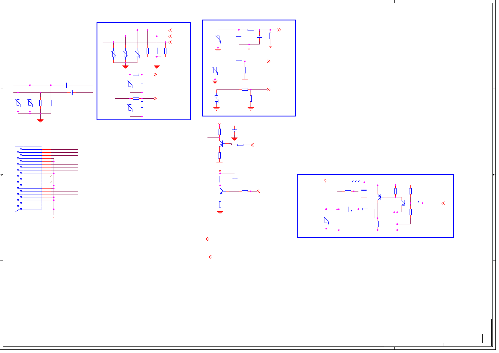
5
4
3
2
1
SCART_RGB
SC-G
SC-B
SC-R
RV74
RV74
RV87
D D
C342
C342
AV_LOUT
AV_ROUT
RV52
RV52
RV53
RV53
R252
R252
R222
AVLC18S02015
AVLC18S02015
AVLC18S02015
AVLC18S02015
C C
XS7XS7
AOR
AIR
AOL
AGND
BGND
AIL
SW
GGND
CLK
DATA
RGND
GND
R/C
BLANK
VGND
BLANKGND
VOUT
V/YIN
SHIELD
B B
R222
10k
10k
10k
10k
AV_ROUT
1
AUR_AV1
2
AV_LOUT
3
4
5
AUL_AV1
6
SC-B
7
B
G
SC-FS
8
9
10
SC-G
11
12
13
14
SC-R
15
SC-FB
16
17
18
AV_out
19
AV1
20
21
C343
C343
2.2u/10V
2.2u/10V
2.2u/10V
2.2u/10V
OUT-L
OUT-R
SCART_MODE
SCART_FB_SUB
RV87
AVLC18S02015
AVLC18S02015
AVLC18S02015
AVLC18S02015
SC-FB
SC-FS
AVLC18S02015
AVLC18S02015
R4210RR421
RV73
RV73
0R
AVLC18S02015
AVLC18S02015
R420
R420
RV79
RV79
8.2k
8.2k
AVLC18S02015
AVLC18S02015
RV64
RV64
75R
75R
75R
75R
R485
R485
R479
R479
75R
75R
R509
R509
SC_FB
SC_FS
75R
75R
R511
R511
R510
R510
75R
75R
SC_FB 2
SC_FS 2
Y1+ 2
PB1+ 2
PR1+ 2
SCART_CVBS_in
R863
R254
R254
10k
10k
C338
C338
100n/25V
100n/25V
R223
R223
100R
100R
C335
C335
100n/25V
100n/25V
R863
0R/NC
0R/NC
C336
C336
220p/50V/NC
220p/50V/NC
AV1_AUL
R255
R255
12k
12k
R259
R259
AV1_AUR
10k
10k
R242
R242
100R
100R
AV1AV1 CVBS0
RV31
RV31
AVLC18S02015
AVLC18S02015
Scart Audio
AUL_AV1
RV36
RV36
AVLC18S02015
AVLC18S02015
AUR_AV1
RV37
RV37
AVLC18S02015
AVLC18S02015
+12V
R498
R498
V17
V17
1.5k
1.5k
OUT-R
3
1
MMBT3904LT1
MMBT3904LT1
2
R492
R492
470R
470R
+12V
R499
R499
V16
V16
1.5k
1.5k
OUT-L
3
1
MMBT3904LT1
MMBT3904LT1
2
R501
R501
470R
470R
C339
C339
220p/50V/NC
220p/50V/NC
75R
75R
R236
R236
12k
12k
AU_ROUT 2
AU_LOUT 2
R504
R504
AV1_AUL 2
AV1_AUR 2
CVBS0
2
SCART_CVBS_out
5VAIN
AV_OUTAV_OUTAV_OUT AV_OUTAV_OUT
RV51
RV51
AVLC18S02015
AVLC18S02015
L9
L9
R208
R208
BLM18PG181SN1
BLM18PG181SN1
0R/NC
0R/NC
C830
C830
330u/6V
330u/6V
C199
C199
560p/50V/NC
560p/50V/NC
R204
R204
75R/NC
75R/NC
C194
C194
2
MMBT3906LT1
MMBT3906LT1
100n/25V
100n/25V
3
V18
V18
R260
R260
150R
150R
1
R243
R243
150R
150R
R246
R246
330R
330R
V19
V19
3
MMBT3904LT1
MMBT3904LT1
2
R241
R241
150R
150R
1
R256
R256
47k
47k
C831
C831
100u/16V
100u/16V
R226
R226
33k
33k
CVBSOut
CVBSOUT 2
+12V
5VAIN
A A
5
4
+12V 1
5VAIN 1
Title
Title
Title
MSD309PX
MSD309PX
MSD309PX
Size Document Number Rev
Size Document Number Rev
Size Document Number Rev
Custom
Custom
Custom
PC/HDTV/AV
PC/HDTV/AV
Date: Sheet of
Date: Sheet of
3
2
Date: Sheet of
PC/HDTV/AV
Saturday, November 27, 2010
Saturday, November 27, 2010
Saturday, November 27, 2010
1
A
A
A
105
105
105
Page 51

Ant_Pwr
RF AGC
SCL
SDA
VCC
IF AGC
DIF OUT+
DIF OUT-
IF OUT
5
5VAIN
ANT_5V_OUT
1
2
NC
VT
AS
T_RF_AGC
3
4
R4250RR425
5
T_SCL_D
6
0R
T_SDA_D
7
5V_TUNER
8
9
10
11
12
IF+
IF-
IF_TV
R440
R440
IF+ 2
100R
100R
IF- 2
T_SCL_D
IF_AGC 2
T_SDA_D
C456
C456
20p/50V/NC
20p/50V/NC
C461
C461
20p/50V/NC
20p/50V/NC
U42
U42
D D
16
GND4
15
GND3
14
GND2
13
GND1
FH2610
FH2610
DVB-T/C TUNER
FR_AGC
RF_AGC
C C
2
5V-IF
RF_AGC
R417
R417
10k
10k
2
V37
V37
MMBT3906LT1
MMBT3906LT1
3
1
R414
R414
100k
100k
V38
V38
3
1
MMBT3904LT1
MMBT3904LT1
2
R442
R442
100R
100R
R404
R404
10k
10k
ANT POWER
+5V_TUNER_TEST
V41
R497
R497
10k
10k
R525
R525
470R
470R
V41
2
1
B B
5V-IF
ANTPWR_ON2
L21
L21
BLM18PG181SN1
BLM18PG181SN1
ANTPWR_ON
R409
R409
10k
10k
C340
C340
10n/50V
10n/50V
C344
C344
10u/16V
10u/16V
V42
V42
1
C347
C347
100n/16V
100n/16V
3
MMBT3904LT1
MMBT3904LT1
2
TUNER POWER
N16
R312
R312
+12V
A A
6.8R/2W
6.8R/2W
R314
R314
6.8R/2W
6.8R/2W
C639
C639
10u/16V
10u/16V
C826
C826
100u/25V
100u/25V
1
Vin
C248
C248
100n/16V
100n/16V
N16
GND
3
2
Vout
CW78D05CZ
CW78D05CZ
C249
C249
100n/16V
100n/16V
4
5VAIN 1
R439
R439
R438
R438
T_SDA 2
T_SCL 2
100R
100R
100R
100R
T_IF_AGCT_IF_AGC
T_RF_AGC
T_RF_AGC
RF_AGC_SEL
RF_AGC_SEL
0: DTV
1: ATV
L56
L56
F526
F526
Fuse/100mA
Fuse/100mA
BLM18PG181SN1/NC
3
AO3401L
AO3401L
5V-IF
C827
C827
100u/25V
100u/25V
BLM18PG181SN1/NC
L1
L1
L24
L24
BLM18PG181SN1/NC
BLM18PG181SN1/NC
BLM18PG181SN1
BLM18PG181SN1
C828
C828
100u/25V
100u/25V
C464
C464
100n/25V
100n/25V
RF_AGC_SEL 2
5VAIN
+12V
C463
C463
100n/25V
100n/25V
12
5V_TUNER
C459
C459
1n/50V
1n/50V
IF_TV
ANT_5V_OUT
1 2
C446
C446
100n/16V
100n/16V
R308
R308
R303
R303
300R
300R
300R
300R
C345
C345
0.01uF
0.01uF
AGND
C220
C220
10n/50V
10n/50V
R297
R297
75R/NC
75R/NC
C346
C346
2.2u/10V
2.2u/10V
R2810RR281
0R
C219
C219
10n/50V
10n/50V
靠近
R283
R283
C230
C230
4.7k
4.7k
10n/50V
10n/50V
R2821kR282
1k
VIF_SW
2
3
Tuner
R2721kR272
V14
V14
1k
1
3
2SC2717
2SC2717
2
VIF_SW
放置
R298
R298
56R
56R
R285
R285
680R
680R
R302
R302
10k/NC
10k/NC
H1NCH1
NC
5
4
3
2
L3
L3
LGA0305-0u82-K
LGA0305-0u82-K
R2840RR284
0R
5V-IF
C235
C235
10n/50V
10n/50V
1
1
5
4
3
2
+12V
1
R326
R326
47k/NC
47k/NC
R291
R291
6.8k/NC
6.8k/NC
R286
R286
2.2k/NC
2.2k/NC
8
7
6
R300
R300
6.8k/NC
6.8k/NC
VD44
VD44
BA277/NC
BA277/NC
1 2
3
V21
V21
MMBT3904LT1/NC
MMBT3904LT1/NC
2
8
7
6
+12V 1
靠近主芯片放置
N58
N58
1
R3040RR304
0R
OUT2
IN1
IN2/SW2OUT1
GND
HS3611
HS3611
3
N6274
0: NTSC
1: PAL
2
C236
C236
C254
C254
100n/16V/NC
100n/16V/NC
线宽
12mil
100n/16V
100n/16V
C252
C252
线宽
12mil
C242
C242
100n/16V
100n/16V
100n/16V/NC
100n/16V/NC
1
1
1
1
VIFM
,包地
,包地
VIFP
8
7
6
8
7
6
8
7
6
8
7
6
VIFM 2
VIFP 2
M7
MARKM7MARK
5
4
3
2
H9NCH9
NC
5
4
3
2
M5
MARKM5MARK
M6
MARKM6MARK
1
H4NCH4
NC
1
5
4
3
2
5
4
3
2
8
7
6
1
1
8
8
7
7
6
6
5
R999
R999
1M/NC
1M/NC
4
H3NCH3
NC
5
5
4
4
3
3
2
2
H8NCH8
NC
5
5
4
4
3
3
2
2
1
M1
MARKM1MARK
M3
MARKM3MARK
H5NCH5
NC
5
5
4
8
7
6
4
3
3
2
2
M2
MARKM2MARK
M4
MARKM4MARK
1
1
8
8
7
7
6
6
Title
Title
Title
MSD309PX
MSD309PX
MSD309PX
Size Document Number Rev
Size Document Number Rev
Size Document Number Rev
Custom
Custom
Custom
TUNER
TUNER
TUNER
Saturday, November 27, 2010
Date: Sheet of
Saturday, November 27, 2010
Date: Sheet of
Saturday, November 27, 2010
5
4
3
2
Date: Sheet of
1
A
A
A
106
106
106
Page 52
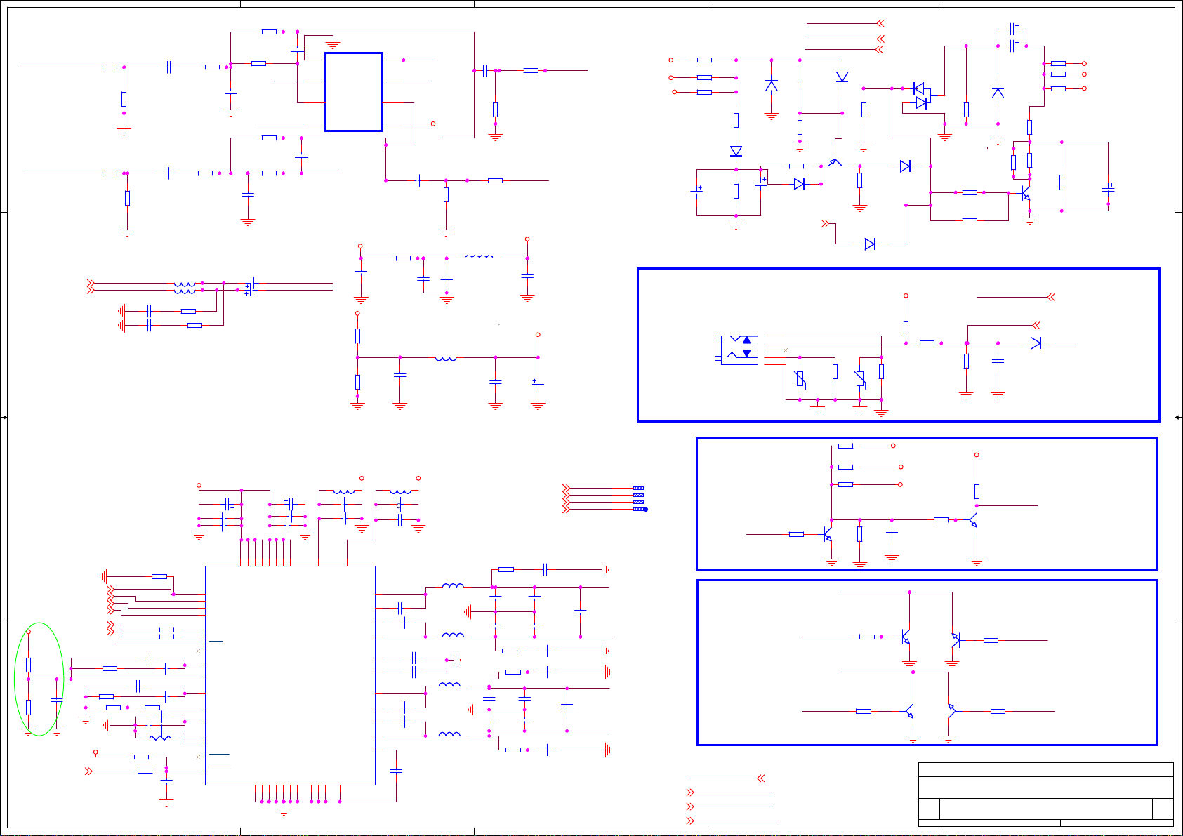
5
R137
R137
C232
47k/NC
Headphone out
EARPHONE_OUTL
D D
EARPHONE_OUTR
EARPHONE_OUTR2
EARPHONE_OUTL
2
C C
R400
R400
0R/NC
0R/NC
R148
R148
10k/NC
10k/NC
R415
R415
0R/NC
0R/NC
R156
R156
10k/NC
10k/NC
EARPHONE_OUTR
EARPHONE_OUTL
C321
C321
C320
C320
10u/16V
10u/16V
10u/16V
10u/16V
C409
C409
10u/16V/NC
10u/16V/NC
C319
C319
10u/16V/NC
10u/16V/NC
L14
L14
L15
L15
10.0 uH
10.0 uH
R486
R486
10.0 uH
10.0 uH
R422
R422
200R
200R
200R
200R
R180
R180
10k/NC
10k/NC
R158
R158
10k/NC
10k/NC
47k/NC
R147
R147
5.1k/NC
5.1k/NC
C200
C200
820p/50V/NC
820p/50V/NC
R195
R195
47k/NC
47k/NC
R159
R159
5.1k/NC
5.1k/NC
C212
C212
820p/50V/NC
820p/50V/NC
C822
C822
C823
C823
100u/16V
100u/16V
100u/16V
100u/16V
C232
120pF
120pF
1 2
OPAVREF
AU1_IN AU2_OUT
AU1_OUT
C164
C164
120pF/NC
120pF/NC
1 2
PH-Rin
PH-Lin
N40
N40
4
VEE
+IN13-IN2
-IN12OUT2
1
OUT1
BA4558FAZ4558CM/NC
BA4558FAZ4558CM/NC
AU2_IN
+12V
OPAV120
4
+IN2
VCC
R132
R132
47k/NC
47k/NC
R131
R131
47k/NC
47k/NC
5
6
7
8
R201
R201
C189
C189
10R/NC
10R/NC
100n/25V/NC
100n/25V/NC
OPAVREF
AU2_IN
C406
C406
10u/16V/NC
10u/16V/NC
C246
C246
100n/25V/NC
100n/25V/NC
C355
C355
10u/16V/NC
10u/16V/NC
OPAV120
AU1_OUT
R154
R154
47k/NC
47k/NC
L4
1 2
4.7uH/NCL44.7uH/NC
C405
C405
C397
C397
10u/16V/NC
10u/16V/NC
10u/16V/NC
10u/16V/NC
L85
L85
BLM18PG181SN1/NC
BLM18PG181SN1/NC
1u/16V/NC
1u/16V/NC
R197
R197
470R/NC
470R/NC
R142
R142
47k/NC
47k/NC
OPAV120
C271
C271
R149
R149
470R/NC
470R/NC
PH-Rin
C211
C211
100n/25V/NC
100n/25V/NC
OPAVREF
3
PH-Lin
24寸用C829,32寸用C821
100u/25V/NC
100u/25V/NC
C824
C824
Mute Circuit
+12V
VCC-A
5Vstb
C829
C829
470u/16V
470u/16V
R4230RR423
R359
R359
0R
R403
R403
0R/NC
0R/NC
0R/NC
0R/NC
12
VD67
VD67
1N4148W
1N4148W
R4111kR411
1k
R410
R410
100k
100k
VD92
VD92
1N4148W/NC
1N4148W/NC
1 2
VD66
VD66
C821
C821
1 2
47u/25V
47u/25V
Headphone jack
XS12
XS12
HeadPhone
HeadPhone
AGND
3
R
4
WR
2
WL
1
L
5
2
R358
R358
1k/NC
1k/NC
R357
R357
47k
47k
R4410RR441
2
MMBT3906LT1
MMBT3906LT1
0R
1N4148W/NC
1N4148W/NC
AMP-MUTE2
PH-Rin
PH-Lin
RV32
RV32
AVLC18S02015/NC
AVLC18S02015/NC
5Vstb
+12V
VCC-A
12
VD42
VD42
1N4148W
1N4148W
V24
V24
1
PWR_OFF_MUTE
3
AMP-MUTE
VD65
VD65
1 2
R299
R299
470R
470R
AVLC18S02015/NC
AVLC18S02015/NC
R419
R419
47k
47k
R443
R443
22k/NC
22k/NC
1N4148W
1N4148W
RV33
RV33
5Vstb 1
+12V 1
VCC-A 1
VD75
VD75
2
3
1
BAV99LT1
BAV99LT1
VD50
VD50
1 2
1N4148W
1N4148W
24寸用R436,32寸用R435
PWD_MT
R362
R362
24寸用R363,32寸用R362
5VAIN
R311
R311
R320
R320
47k
47k
HP_DET
HP_DETHP_DETHP_DETHP_DETHP_DETHP_DET
10k
10k
R343
R343
470R
470R
R3631kR363
1k
VD91
VD91
1N4148W/NC
1N4148W/NC
R375
R375
100k
100k
10k
10k
HP_DET
R321
R321
10k/NC
10k/NC
R436
R436
8.2k
8.2k
220u/25V
220u/25V
1
C832
C832
24寸用C832,32寸用C820
R407
R407
C820
47u/25V
47u/25V
1 2
C820
1
5VAIN
C392
C392
10u/10V
10u/10V
R424
R424
10k
10k
SHUTDOWN
R4350RR435
0R
V23
V23
3
MMBT3904LT1
MMBT3904LT1
2
HP_DET 2
VD54
VD54
1 2
1N4148W
1N4148W
0R/NC
0R/NC
R374
R374
R4050RR405
0R/NC
0R/NC
0R
R360
R360
10k/NC
10k/NC
5VAIN 1
PWD_MT
+12V
VCC-A
5Vstb
22u/16V
22u/16V
C247
C247
24寸用C247,32寸不用
R329
R329
0R/NC
0R/NC
R327
R327
R325
R325
22k
22k
0R/NC
0R/NC
V33
V33
3
MMBT3904LT1
MMBT3904LT1
2
2
AGND
PH-Lin
PH-Rin
R418
R418
10k
10k
R413
R413
10k
10k
DGND
R328
R328
10k
10k
+12V
VCC-A
5Vstb
C245
C245
10u/10V/NC
10u/10V/NC
V28
V28
3
1
MMBT3904LT1
MMBT3904LT1
2
V35
V35
3
1
MMBT3904LT1
MMBT3904LT1
2
Title
Title
Title
Size Document Number Rev
Size Document Number Rev
Size Document Number Rev
Date: Sheet of
Date: Sheet of
Date: Sheet of
R50
R50
1
10k
10k
V34
V34
2
3
V36
V36
2
3
MSD309PX
MSD309PX
MSD309PX
Custom
Custom
Custom
Tuesday, January 11, 2011
Tuesday, January 11, 2011
Tuesday, January 11, 2011
33V_Normal
R35
R35
4.7k
4.7k
MUTE_5707
V43
V43
3
MMBT3904LT1
MMBT3904LT1
2
0:PWM Stop
1:PWM Normal
R416
R416
PWR_OFF_MUTE
1
MMBT3904LT1
MMBT3904LT1
10k
10k
R426
R426
1
MMBT3904LT1
MMBT3904LT1
10k
10k
Audio Amplifier
Audio Amplifier
Audio Amplifier
1
A
A
A
710
710
710
GND
Amplifier
33V_Normal
L89
PVDD_D_44
AVSS
DVSS28GND29AGND
30
L89
C129 10uFC129 10uF
1 2
C125
C125
BLM18PG181SN1
BLM18PG181SN1
100n/25V
100n/25V
27
13
AVDD
GVDD_OUT_31
GVDD_OUT
STEST
EPAD
26
49
DVDD
OUT_A
BST_A
BST_B
OUT_B
OUT_C
BST_C
BST_D
OUT_D
VREG
4
VCC-A
C825
C825
C127
C127
C181
C181
100u/25V
15
21
20
22
24
23
19
8
11
12
10
16
18
6
7
14
25
100u/25V
100n/25V
100n/25V
100n/25V
100n/25V
N17
N17
MCLK
SCLK
LRCLK
SDIN
SCL
SDA
PDN_18
NC
PLL_FLTP
VR_ANA
PLL_FLTM
OSC_RES
VR_DIG
SSTIMER
OC_ADJ
FAULT_13
RESET_24
2
B B
R59
R59
I2C-SCL2,10
I2C-SDA2,10
R324
R324
R318
R318
470R
470R
470R
470R
33V_Normal
AMP-RST
I2S_OUT_MCK
I2S_OUT_BCK
I2S_OUT_LRCK
I2S_OUT_SD
MUTE_5707
R317
R317
200R
200R
5
10k/NC
10k/NC
C128
C128
C130
C130
4.7n/50V
4.7n/50V
R144
R144
4.7n/50V
4.7n/50V
C277
C277
C155
C155
C182
C182
18k
18k
4.7u/10V
4.7u/10V
R58 22K1
R58 22K1
1 2
100n/25V
100n/25V
R323
R323
2.2n/50V/NC
2.2n/50V/NC
R346
R346
10k
10k
100R
100R
R387
R387
R349
R349
22R
22R
22R
22R
C290
C290
C172
C172
4.7n/50V
4.7n/50V
4.7n/50V
4.7n/50V
R-RESC1608N-HX
R-RESC1608N-HX
C286
C286
100n/25V
100n/25V
I2S_OUT_MCK2
I2S_OUT_BCK2
I2S_OUT_LRCK2
I2S_OUT_SD2
33V_Normal
R136
R136
47k/NC
47k/NC
C256
C256
R133
R133
100n/25V/NC
100n/25V/NC
47k/NC
47k/NC
A A
Present for eleminating pop,C256close to 12 PIN
AMP-RST2
C851
C851
C126
C126
C163
C163
100u/25V
100u/25V
100n/25V
100n/25V
100n/25V
100n/25V
35
41
34
40
44
45
3
PVDD_A
PVDD_B
PVDD_D
PVDD_C
PVDD_A_7
PVDD_B_46
PVDD_C_29
TAS5707
TAS5707
TAS5707PHP
DVSSO
PGND_CD37PGND_CD_5
PGND_AB47PGND_AB_2
9
17
38
48
33V_Normal
L90
L90
C121 10uFC121 10uF
1 2
BLM18PG181SN1
BLM18PG181SN1
C119
C119
100n/25V
100n/25V
1
C165
C165
4
C288
C288
43
33n/50V
33n/50V
46
33n/50V
33n/50V
C124
C124
5
C293
C293
32
1u/50V
1u/50V
1u/50V
1u/50V
39
C504
C504
42
C322
C322
33
33n/50V
33n/50V
36
33n/50V
33n/50V
31
C285
C285
100n/25V
100n/25V
L25
L25
22.0 uH
22.0 uH
L29
L29
22.0 uH
22.0 uH
L26
L26
22.0 uH
22.0 uH
L28
L28
22.0 uH
22.0 uH
AMP-R+10
AMP-R-10
AMP-L-10
AMP-L+10
R389
R389
56R/NC
56R/NC
C166
C166
470n/50V
470n/50V
C154
C154
470n/50V
470n/50V
R385
R385
R392
R392
56R/NC
56R/NC
56R/NC
56R/NC
C507
C507
470n/50V
470n/50V
C173
C173
470n/50V
470n/50V
R386
R386
56R/NC
56R/NC
C217
C217
10n/50V/NC
10n/50V/NC
C142
C142
220n/50V
220n/50V
C179
C179
220n/50V
220n/50V
C215
C215
C213
C213
10n/50V/NC
10n/50V/NC
10n/50V
10n/50V
C334
C334
220n/50V
220n/50V
C503
C503
220n/50V
220n/50V
C206
C206
10n/50V/NC
10n/50V/NC
AMP-R+
AMP-R-
AMP-L-
AMP-L+
AMP-R+
AMP-R-
AMP-L-
C508
C508
680n/16V/NC
680n/16V/NC
AMP-L+
3
C180
C180
680n/16V/NC
680n/16V/NC
XP6XP6
4
3
2
1
PH-Lin7
PH-Rin7
SHUTDOWN7
Amplifier Mute
R332
R332
SHUTDOWNSHUTDOWN
10k
10k
Headphone Mute
PWR_OFF_MUTE
PWR_OFF_MUTE PWR_OFF_MUTE
33V_Normal
33V_Normal 1
PH-Lin
PH-Rin
SHUTDOWN
1
Page 53

5
4
3
2
1
5VAIN
D D
5VAIN 1
Power for USB
5VAIN
C C
L46
L46
STPB2012-121PT
STPB2012-121PT
MMBT3904LT1 /NC
MMBT3904LT1 /NC
+5V_USB
C115
C115
100n/16V
100n/16V
V25
V25
3
2
R61
R61
4.7k/NC
4.7k/NC
1
1u/16V/NC
1u/16V/NC
C120
C120
1u/16V
1u/16V
R49
R49
C114
C114
4.7k/NC
4.7k/NC
L888
L888
STPB2012-121PT
STPB2012-121PT
N28
N28
AO4459 /NC
AO4459 /NC
1
S1
2
S2
3
S3
4
G
D1
D1
D2
D2
ON_USB 2
5V_USB
8
7
6
5
100u/16V
100u/16V
C817
C817
USB Input
Shield
6
R42
RV8
RV8
R42
R43
R43
5.1R
5.1R
5.1R
5.1R
USB0_DP
USB0_DMUSB1_D1-_in
USB0_DP 2
USB0_DM 2
4
GND
3
D+
GND5GND
2
D -
1
B B
VCC
XP15XP15
5V_USB
USB1_D1+_in
RV7
RV7
ASES12U020R2/NC
ASES12U020R2/NC
ASES12U020R2/NC
ASES12U020R2/NC
SH2SH2
1
2
3
4
A A
Title
Title
Title
Size Document Number Rev
Size Document Number Rev
Size Document Number Rev
Date: Sheet of
Date: Sheet of
Date: Sheet of
5
4
3
MSD309PX
MSD309PX
MSD309PX
A
A
A
USB
USB
USB
Saturday, November 27, 2010
Saturday, November 27, 2010
Saturday, November 27, 2010
2
A
A
A
1010
1010
1010
1
 Loading...