

Page 1
UD 16 /
UD 30
Bedienungsanleitung de
Operating instructions en
Mode d’emploi fr
Manual de instrucciones es
Istruzioni d’uso it
Gebruiksaanwijzing nl
Brugsanvisning da
Bruksanvisning no
Bruksanvisning sv
Käyttöohje fi
Manual de instruções pt
ΟΟδδηηγγιιεεςς χχρρηησσεεωωςς
el
Lietoßanas pamåcîba lv
Instrukcija lt
Kasutusjuhend et
ar
Page 2
12
15 6
8
9
+≠
7
12
2
4
3
UD 30
UD 16
1
Page 3
2
12
1
3/4
2/5
3
1
23
4
2
3/4
5
3
2
4
1
6
2
5
31
6
4
7
8
2
1
3
4
9
4
1
12
3
2
5
1 2
Page 4
10
2
3
1
11
1
3
4
2
12
Page 5
UD 16 / UD 30 drill
It is essential that the operating instructions
are read before the power tool is operated
for the first time.
Always keep these operating instructions
together with the power tool.
Ensure that the operating instructions are
with the power tool when it is given to other
persons.
Contents Page
1. General information 17
2. Description 18
3. Accessories 21
4. Technical data 21
5. Safety rules 22
6. Before use 25
7. Operation 25
8. Care and maintenance 28
9. Troubleshooting 28
10. Disposal 29
11. Manufacturer’s warranty ‐ tools 29
12. EC declaration of conformity 30
1. General information
1 These numbers refer to the corresponding illustrations. The illustrations can be found on the fold‐out
cover pages. Keep these pages open while studying
the operating instructions.
In these operating instructions, the designation “the
power tool” always refers to the UD 16 or UD 30
electric drill.
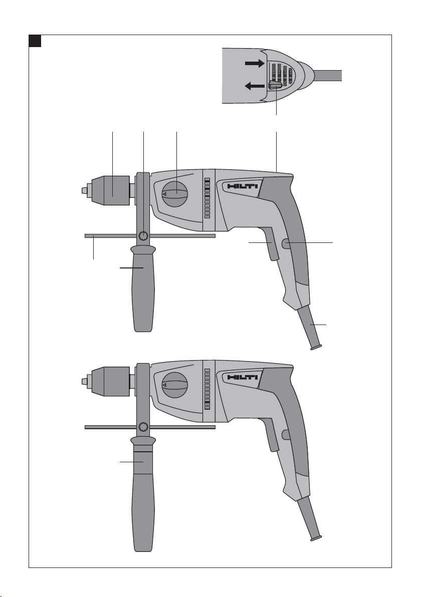
Operating controls and parts 1
Chuck (keyless chuck or key chuck with key)
@
Side handle
;
Sleeve (only UD 16)
=
Depth gauge
%
Depth gauge locking screw
&
Function selector switch
(
Forward / reverse switch
)
Control switch with electronic speed control
+
Lockbutton for sustained operation
§
Supply cord
/
en
1.1 Safety notices and their meaning
WARNING
Draws attention to a potentially dangerous situation
that could lead to serious personal injury or fatality.
CAUTION
Draws attention to a potentially dangerous situation
that could lead to slight personal injury or damage to
the equipment or other property.
NOTE
Draws attention to an instruction or other useful
information.
1.2 Explanation of the pictograms and other
information
Warning signs
General
warning
Warning:
electricity
17
Page 6
Obligation signs
Wear a hard
en
protective
gloves
Symbols
hat
Wear
Wear eye
protection
Wear
breathing
protection
Wear ear
protection
Location of identification data on the power tool
The type designation, item number, year of manufacture and technical status can be found on the
type identification plate on the machine or tool. The
serial no. can be found on the underside of the motor
housing. Make a note of this data in your operating
instructions and always refer to it when making an
enquiry to your Hilti representative or service department.
Type:
Serial no.:
1
Read the
operating
instructions
before use
Amps Hertz Volts Watts
Alternating
current
Return waste
material for
recycling.
Double
insulated
Drilling, 1st
gear
2
Drilling, 2nd
gear
2. Description
2.1 Use of the product as directed
The power tool is a hand‐held, mains‐powered electric drill for drilling in wood and metal and for screwdriving.
Under certain conditions, the power tool is also suitable for mixing (see “Applications”).
The working environment may be as follows: construction site, workshop, renovation, conversion or new
construction, where the types of work listed above may be carried out.
The power tool may be operated only when connected to a power supply providing a voltage and frequency in
compliance with the information given on its type identification plate.
Modification of the power tool or tampering with its parts is not permissible.
The power tool is designed for professional use and may be operated, serviced and maintained only by trained,
authorized personnel. This personnel must be informed of any special hazards that may be encountered. The
power tool and its ancillary equipment may present hazards when used incorrectly by untrained personnel or
when used not as directed.
To avoid the risk of injury, use only genuine Hilti accessories and insert tools.
Observe the information printed in the operating instructions concerning operation, care and maintenance.
18
Page 7

Working on materials hazardous to the health (e.g. asbestos) is not permissible.
The power tool may be used only in a dry environment.
Do not use the power tool where there is a risk of fire or explosion.
2.2 Chuck
Keyless chuck or
Key chuck with key
2.3 Switches
Control switch with electronic speed control
Lockbutton for sustained operation
Function selector switch
Forward / reverse switch
2.4 Grips
Vibration‐absorbing side handle with depth gauge
Vibration‐absorbing grip
2.5 Possible applications
en
UD 16 applications Insert tool type
Drilling in metal Drill bits with smooth
shank
Stepped drill bits
Drilling in wood Twist drills
Forstner drill bits
Hole saws
Auger bits
Flat bits (not self‐
cutting)
Driving Drywall screws
Frame anchors (HRD)
Universal anchors
(HUD)
Mixing dispersion paint, thin
cement mortar, tile adhesive and
plaster with mixing paddles
UD 30 applications Insert tool type
Drilling in metal Drill bits with smooth
TE‑MP 80
TE‑MP 110
shank
Stepped drill bits
Drill bit sizes, 1st
gear
Max. 13 mm
Max. 35 mm
Max. 30 mm
Max. 40 mm
Max. 80 mm
Max. 30 mm
Max. 40 mm
6/300 mm
10/50 ‑ 120 mm
12/60 mm
Recommended
Recommended
Drill bit sizes, 1st
gear
Max. 13 mm
Max. 35 mm
Drill bit sizes, 2nd
gear
Max. 6 mm
Max. 10 mm
Max. 30 mm
Max. 40 mm
Max. 40 mm
‐
Max. 40 mm
‐
‐
‐
‐
‐
Drill bit sizes, 2nd
gear
1.5…8 mm
Max. 8 mm
19
Page 8

UD 30 applications Insert tool type
Drilling in wood Twist drills
Forstner drill bits
Hole saws
en
Driving Drywall screws 6/60 mm
2.6 Items supplied as standard
1 Power tool with side handle
1 Depth gauge
1 Chuck key (with keyed chuck)
1 Operating instructions
1 Hilti cardboard box or toolbox
2.7 Using extension cords
Use only extension cords of a type approved for the application and with conductors of adequate cross section.
The power tool may otherwise loose performance and the extension cord may overheat. Check the extension
cord for damage at regular intervals. Replace damaged extension cords.
Recommended minimum conductor cross section and max. cable lengths for the UD 16:
Conductor cross section 1.5 mm² 2mm² 2.5 mm² 3.5 mm²
Mains voltage 100V 30 m 50 m
Mains voltage 110‐120 V 30 m 50 m
Mains voltage 220‐240 V 90 m 140 m
Recommended minimum conductor cross section and max. cable lengths for the UD 30:
Conductor cross section 1.5 mm² 2mm² 2.5 mm² 3.5 mm²
Mains voltage 100V 40 m 60 m
Mains voltage 110‐120 V 30 m 50 m
Mains voltage 220‐240 V 100 m 160 m
Do not use extension cords with 1.25 mm² conductor cross section.
Auger bits
Flat bits (not self‐
cutting)
Drill bit sizes, 1st
gear
Max. 25 mm
Max. 40 mm
Max. 50 mm
Max. 20 mm
Max. 30 mm
Drill bit sizes, 2nd
gear
Max. 20 mm
Max. 25 mm
‐
‐
Max. 30 mm
‐
2.8 Using extension cords outdoors
When working outdoors, use only extension cords that are approved and correspondingly marked for this
application.
2.9 Using a generator or transformer
This power tool may be powered by a generator or transformer when the following conditions are fulfilled:
The unit must provide a power output in watts of at least twice the value printed on the type identification
plate on the power tool. The operating voltage must remain within +5% and ‐15% of the rated voltage at all
times, frequency must be in the 50 – 60 Hz range and never above 65 Hz, and the unit must be equipped with
automatic voltage regulation and starting boost.
20
Page 9

Never operate other power tools or appliances from the generator or transformer at the same time. Switching
other power tools or appliances on and off may cause undervoltage and / or overvoltage peaks, resulting in
damage to the power tool.
3. Accessories
The list of insert tools can be found in Section 2 under “Possible applications”.
Keyless chuck
Key chuck
Chuck key (with keyed chuck)
4. Technical data
Right of technical changes reserved.
en
Rated
voltage
Rated power
input, UD 16
Rated current input,
UD 16
Rated power
input, UD 30
Rated current input,
UD 30
Power tool UD 16 UD 30
Mains frequency
Weight of tool without side handle
Weight in accordance with EPTA
procedure 01/2003
Dimensions (L x W x H) 342 mm x 86 mm x 205 mm 337 mm x 86 mm x 205 mm
Speed in 1st gear under no load
Speed in 2nd gear under no load
Chuck Ø
Maximum torque, 1st gear 80 Nm 51 Nm
Maximum torque, 2nd gear 29 Nm 18.5 Nm
Speed control Electronic, by way of the control
Forward / reverse
Tightening torque for changing
chuck
100 V 110 V 120 V 220 V 230 V 240 V
710 W 710 W 710 W 710 W 710 W
7.5 A 6.9 A 8 A 3.5 A 3.1 A 3.1 A
650 W 650 W 650 W 650 W 650 W
6.9 A 6.5 A 6.5 A 3.1 A 2.9 A 2.9 A
50…60 Hz 50…60 Hz
2.4 kg 2.3 kg
2.6 kg 2.5 kg
900 r.p.m. 1,200 r.p.m.
2,500 r.p.m. 3,300 r.p.m.
1.5…13 mm 1.5…13 mm
Electronic, by way of the control
switch
Switching lever with interlock to
prevent switching while running
120 Nm 120 Nm
switch
Switching lever with interlock to
prevent switching while running
21
Page 10

Noise and vibration information (measured in accordance with EN 60745 ):
Typical A‐weighted sound power level 97 dB (A)
Typical A‐weighted emission sound pressure level 86 dB (A)
Uncertainty for the given sound level
3 dB (A)
Triaxial vibration values (vibration vector sum) Measured in accordance with EN 60745‑2‑2
Screwdriving without impact action, a
en
h
< 2.5 m/s²
Uncertainty (K) 1.5 m/s²
Additional information about the UD 16
Triaxial vibration values (vibration vector sum) Measured in accordance with EN 60745‑2‑1
Drilling in metal, (a
) < 2.5 m/s²
h, D
Uncertainty (K) 1.5 m/s²
Additional information about the UD 30
Triaxial vibration values (vibration vector sum) Measured in accordance with EN 60745‑2‑1
Drilling in metal, (a
) 3.5 m/s²
h, D
Uncertainty (K) 1.5 m/s²
Information about the power tool and its applications
Protection class Protection class II (double insulated)
5. Safety rules
5.1 General power tool safety warnings
WARNING! Read all instructions! Failure to follow all
instructions listed below may result in electric shock,
fire and/or serious injury. The term “power tool” in
all of the warnings listed below refers to your mains‐
operated (corded) power tool or battery‐operated
(cordless) power tool. SAVE THESE INSTRUCTIONS.
5.1.1 Work area safety
a) Keep work area clean and well lit. Cluttered or
dark areas invite accidents.
b) Do not operate power tools in explosive atmo-
spheres, such as in the presence of flammable
liquids, gases or dust. Power tools create sparks
which may ignite the dust or fumes.
c) Keep children and bystanders away while oper-
ating a power tool. Distractions can cause you to
lose control.
5.1.2 Electrical safety
a) Power tool plugs must match the outlet. Never
modify the plug in any way. Do not use any
adapter plugs with earthed (grounded) power
tools. Unmodified plugs and matching outlets will
reduce risk of electric shock.
b) Avoid body contact with earthed or grounded
surfaces such as pipes, radiators, ranges and
refrigerators. There is an increased risk of electric
shock if your body is earthed or grounded.
c) Do not expose power tools to rain or wet con-
ditions. Water entering a power tool will increase
the risk of electric shock.
d) Do not abuse the cord. Never use the cord for
carrying, pulling or unplugging the power tool.
Keep cord away from heat, oil, sharp edges
or moving parts. Damaged or entangled cords
increase the risk of electric shock.
e) When operating a power tool outdoors, use an
extension cord suitable for outdoor use. Use of a
cord suitable for outdoor use reduces the risk of
electric shock.
5.1.3 Personal safety
a) Stay alert, watch what you are doing and use
common sense when operating a power tool. Do
not use a power tool while you are tired or under
the influence of drugs, alcohol or medication. A
moment of inattention while operating power tools
may result in serious personal injury.
22
Page 11

b) Use safety equipment. Always wear eye pro-
tection. Safety equipment such as dust mask,
non‐skid safety shoes, hard hat, or hearing protection used for appropriate conditions will reduce
personal injuries.
c) Avoid accidental starting. Ensure the switch is
in the off‐position before plugging in. Carrying
power tools with your finger on the switch or
plugging in power tools that have the switch on
invites accidents.
d) Remove any adjusting key or wrench before
turning the power tool on. A wrench or a key left
attached to a rotating part of the power tool may
result in personal injury.
e) Do not overreach. Keep proper footing and bal-
ance at all times. This enables better control of
the power tool in unexpected situations.
f) Dress properly. Do not wear loose clothing or
jewellery. Keep your hair, clothing and gloves
away from moving parts. Loose clothes, jewellery
or long hair can be caught in moving parts.
g) Ifdevices are provided for the connection of dust
extraction and collection facilities, ensure these
are connected and properly used. Use of these
devices can reduce dust‐related hazards.
5.1.4 Power tool use and care
a) Do not force the power tool. Use the correct
power tool for your application. The correct power
tool will do the job better and safer at the rate for
which it was designed.
b) Do not use the power tool if the switch does not
turn it on and off. Any power tool that cannot be
controlled with the switch is dangerous and must
be repaired.
c) Disconnect the plug from the power source
and/or the battery pack from the power tool
before making any adjustments, changing accessories, or storing power tools. Such prevent-
ive safety measures reduce the risk of starting the
power tool accidentally.
d) Storeidle power tools out of the reach of children
and do not allow persons unfamiliar with the
power tool or these instructions to operate the
power tool. Power tools are dangerous in the
hands of untrained users.
e) Maintain power tools. Check for misalignment or
binding of moving parts, breakage of parts and
any other condition that may affect the power
tool’s operation. If damaged, have the power
tool repaired before use. Many accidents are
caused by poorly maintained power tools.
f) Keep cutting tools sharp and clean. Properly
maintained cutting tools with sharp cutting edges
are less likely to bind and are easier to control.
g) Use the power tool, accessories and tool bits
etc., in accordance with these instructions and
in the manner intended for the particular type
of power tool, taking into account the working
conditions and the work to be performed. Use of
the power tool for operations different from those
intended could result in a hazardous situation.
5.1.5 Service
a) Have your power tool serviced by a qualified
repair person using only identical replacement
parts. This will ensure that the safety of the power
tool is maintained.
5.2 Additional safety precautions
5.2.1 Personal safety
a) Wear ear protectors. Exposure to noise can cause
hearing loss.
Use auxiliary handles supplied with the tool.
b)
Loss of control can cause personal injury.
c) Always hold the power tool securely with both
hands on the grips provided. Keep the grips dry,
clean and free from oil and grease.
d) Check that the side handle is fitted correctly and
tightened securely.
e) Wear a dust mask.
f) Improve the blood circulation in your fingers by
relaxing your hands and exercising your fingers
during breaks between working.
g) Avoid touching rotating parts. Switch the power
tool on only after bringing it into position at
the workpiece. Touching rotating parts, especially
rotating insert tools, may lead to injury.
h) Operate the power tool only as intended and
when it is in faultless condition.
i) Wear protective gloves when changing insert
tools as the insert tools get hot during use.
j) Always lead the supply cord and extension cord
away from the power tool to the rear while
working. This helps to avoid tripping over the cord
while working.
k) Do not use damaged insert tools.
l) If the work involves breaking right through, take
the appropriate safety measures at the opposite
en
23
Page 12

side. Parts breaking away could fall out and / or
fall down and injure other persons.
m)Always engage 1st gear when mixing. This will
help to avoid splashing or spillage. Wear protective gloves.
5.2.2 Power tool use and care
en
a) Secure the workpiece. Use clamps or a vice
to secure the workpiece. The workpiece is thus
held more securely than by hand and both hands
remain free to operate the power tool.
b) Check that the insert tools used are compatible
with the chuck system and that they are secured
in the chuck correctly.
c) Switch the power tool off and unplug the supply
cord in the event of a power failure or interruption
in the electric supply. Release the switch lockbutton (if applicable). This will prevent accidental
restarting when the electric power returns.
while working. Disconnect the supply cord plug
from the power outlet. Damaged supply cords or
extension cords present a risk of electric shock.
c) Dirty or dusty power tools which have been
used frequently for work on conductive materials should be checked at regular intervals at a
Hilti Service Center. Under unfavorable circum-
stances, dampness or dust adhering to the surface
of the power tool, especially dust from conductive
materials, may present a risk of electric shock.
d) When working outdoors with an electric tool
check to ensure that the tool is connected to the
electric supply by way of a ground fault circuit
interrupter (RCD) with a rating of max. 30 mA
(tripping current). Use of a ground fault circuit
interrupter reduces the risk of electric shock.
e) Use of a ground fault circuit interrupter (RCD
residual current device) with a maximum tripping
current of 30 mA is recommended.
5.2.3 Electrical safety
a) Before beginning work, check the working area
(e.g. using a metal detector) to ensure that no
concealed electric cables or gas and water pipes
are present. External metal parts of the power tool
may become live, for example, when an electric
cable is damaged accidentally. This presents a
serious risk of electric shock.
b) Check the power tool’s supply cord at regular
intervals and have it replaced by a qualified
specialist if found to be damaged. Check extension cords at regular intervals and replace
them if found to be damaged. Do not touch the
supply cord or extension cord if it is damaged
5.2.4 Work area safety
a) Ensure that the workplace is well lit.
b) Ensure that the workplace is well ventilated.
Exposure to dust at a poorly ventilated workplace
may result in damage to the health.
5.2.5 Personal protective equipment
The user and any other persons in the vicinity must
wear suitable eye protection, a hard hat, ear protection, protective gloves and breathing protection
while the power tool is in use.
24
Page 13
6. Before use
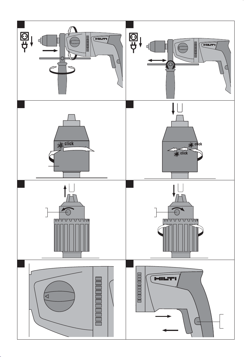
6.1 Fitting and adjusting the side handle 2
CAUTION
Remove the depth gauge from the side handle and
the insert tool from the chuck in order to avoid
injury.
1. Disconnect the supply cord plug from the power
outlet.
2. Release the side handle clamping band by turning
the handle counterclockwise.
3. CAUTION With the UD 16 it is essential to ensure
that the sleeve is fitted in the grip section of the
side handle.
Slip the side handle (clamping band) over the
chuck and push it onto the collar around the
gearing section as far as it will go.
7. Operation
Use auxiliary handles supplied with the tool. Loss
of control can cause personal injury.
WARNING
Do not attempt to use the tool to unscrew screws or
nuts or to free sticking drill bits when the maximum
torque in reverse rotation (see technical data) is
inadequate. There is a risk that the chuck may
become detached from the tool.
4. CAUTION Check that the ribs on the clamping
band engage in the grooves in the collar around
the gearing section.
CAUTION If the side handle slips in the event of
the drill bit sticking while drilling, check that the
ribs on the side handle clamping band engage
securely with the collar on the power tool. Have
any damaged parts replaced. The side handle
will otherwise be unable to take up the torque
generated by the electric tool.
Pivot the side handle into the desired position (it
engages at a number of set positions).
5. Secure the side handle by turning the grip clockwise.
6.2 Use of extension cords and generators or
transformers
See section “Description / use of extension cords”.
7.1 Preparing for use
7.1.1 Fitting and adjusting the depth gauge 3
1. Disconnect the supply cord plug from the power
outlet.
2. Release the depth gauge locking screw.
3. Push the depth gauge into the opening provided.
4. Adjust the depth gauge to the desired drilling
depth.
5. Tighten the depth gauge locking screw securely.
7.2 Operation
en
WARNING
The electric supply voltage must comply with the
information given on the type identification plate
on the power tool.
CAUTION
Use clamps or a vice to hold the workpiece securely.
CAUTION
Working on the material may cause it to splinter.
Wear eye protection and protective gloves. Wear
breathing protection if no dust removal system is
25
Page 14

used. Splintering material presents a risk of injury to
the eyes and body.
CAUTION
The work generates noise. Wear ear protectors.
Exposure to noise can cause hearing loss.
CAUTION
en
The insert tool and the chuck get hot during use.
Wear protective gloves when changing insert tools.
7.2.1 Keyless chuck
CAUTION
Disconnect the supply cord plug from the power
outlet.
NOTE
The keyless chuck may have to be rotated slightly by
hand before the built‐in drive spindle lock engages.
NOTE
Depending on the type of chuck fitted, either the broad
adjusting ring or the rear gripping ring on the chuck
must be held securely by hand.
NOTE
Use the key supplied to open the chuck and to tighten
it after inserting a tool.
7.2.2.1 Opening the key chuck 6
1. Insert the chuck key in one of the three holes
provided in the chuck.
2. Open the chuck by turning the key in a counterclockwise direction.
3. Remove the tool from the chuck.
4. Remove the chuck key.
7.2.2.2 Closing the key chuck 7
1. Open the key chuck far enough to allow the shank
of the tool to be inserted.
2. Insert the shank of the tool in the chuck.
3. Close the jaws by turning the rotatable toothed
ring until the tool is gripped by the chuck.
4. Insert the chuck key in one of the three holes
provided in the chuck.
5. Tighten the chuck by turning the chuck key in a
clockwise direction until the tool is held securely.
6. Remove the chuck key.
7.2.1.1 Opening the keyless chuck 4
1. Grip the rotatable sleeve.
2. Turn the sleeve counterclockwise.
NOTE First, the locking mechanism will be released automatically.
3. Continue turning the sleeve until the insert tool is
released.
7.2.1.2 Closing the keyless chuck 5
1. Open the keyless chuck far enough to allow the
shank of the tool to be inserted.
2. Insert the shank of the tool in the keyless chuck.
3. Tighten the chuck by turning the rotatable sleeve
firmly in a clockwise direction.
4. After the jaws of the chuck begin to grip the tool,
continue turning the rotatable sleeve in a clockwise direction until the keyless chuck engages
and locks automatically.
NOTE The chuck must be heard to engage (several
clicks).
7.2.2 Key chuck
CAUTION
Disconnect the supply cord plug from the power
outlet.
7.2.3 Possible applications
CAUTION
In accordance with the applications for which it is
designed, the power tool produces a high torque.
Always use the side handle and hold the power
tool with both hands. The user must be prepared for
sudden sticking and stalling of the insert tool.
CAUTION
If stalling occurs, switch off the motor immediately.
The power tool may suffer damage if stalled for longer
than 2‐3 seconds.
CAUTION
Do not operate the function selector switch while
the motor is running.
NOTE
The forward / reverse switch must be set to the
“forward” position.
26
Page 15

7.2.3.1 Rotary drilling, 1st and 2nd gear 8
1. Turn the function selector switch to the 1st or
2nd gear rotary drilling position until it engages.
It may be necessary to turn the drive spindle
slightly.
2. Bring the side handle into the desired position
and check that it is fitted correctly and secured.
3. Plug the supply cord into the power outlet.
4. Position the power tool and drill bit at the point
where the hole is to be drilled.
5. Press the control switch slowly (drill at a low
speed until the drill bit centers itself in the hole).
6. Press the control switch fully to continue working
at full power.
7. Adjust the pressure applied to the power tool
according to the material you are working on. This
will ensure the optimum rate of drilling progress.
7.2.3.2 Mixing
1. Turn the function selector switch to the 1st gear
rotary drilling position until it engages. It may be
necessary to turn the drive spindle slightly.
2. Bring the side handle into the desired position
and check that it is fitted correctly and secured.
3. Plug the supply cord into the power outlet.
4. Position the mixing paddle in the container holding the substance to be mixed.
5. To begin mixing, press the control switch slowly.
6. Press the control switch fully to continue working
at full power.
7. Guide the mixing paddle carefully in order to avoid
splashing and spillage.
7.2.3.3 Screwdriving
NOTE
Set the forward / reverse switch to suit the screwdriving operation to be carried out.
1. Turn the function selector switch to the 1st or
2nd gear rotary drilling position until it engages.
It may be necessary to turn the drive spindle
slightly.
2. Bring the side handle into the desired position
and check that it is fitted correctly and secured.
3. Plug the supply cord into the power outlet.
4. Press the control switch slowly until the screw
grips and is guided by the material into which it
is being driven.
5. Continue pressing the control switch, applying
power appropriate to the material you are working
on.
6. Reduce speed toward the end of the screwdriving
operation in order to avoid damage.
7.2.4 Control switch with electronic speed
control
The speed of the power tool can be varied continuously up to maximum speed by slowly increasing
pressure on the control switch.
7.2.5 Lockbutton for sustained operation
The lockbutton for sustained operation is used to lock
the control switch in the “on” position. The motor
then runs constantly at full speed.
7.2.5.1 Switching on in sustained operating
mode 9
1. Press the control switch and hold it in this position.
2. Press the lockbutton and hold it in this position.
3. Release the control switch.
4. Release the lockbutton.
7.2.5.2 Switching off after sustained operation
Press the control switch again to release the lockbutton.
7.2.6 Forward / reverse
CAUTION
Do not operate the forward / reverse switch while
the motor is running.
Turn the switch lever to the “forward” or “reverse”
position, depending on the work to be carried out.
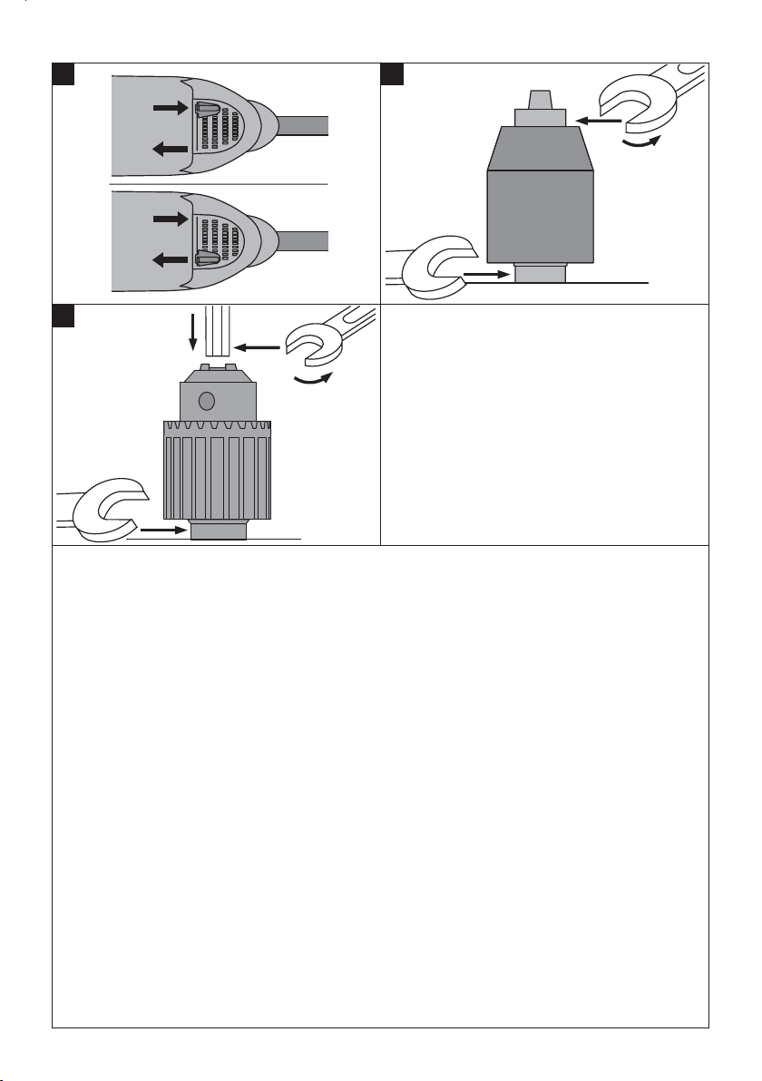
7.3 Changing the chuck
7.3.1 Removing the keyless chuck
1. Grip the flat section of the drive spindle with a 17
mm AF open‐end wrench.
2. Grip the hexagonal section of the keyless chuck
with a 19 mm AF ring or open‐end wrench.
3. Turn the 19 mm AF open‐end wrench in a counterclockwise direction.
The keyless chuck will be unscrewed from the
drive spindle.
7.3.2 Removing the key chuck
1. Insert a short length of hexagonal steel in the
chuck and then tighten the chuck jaws until the
hexagonal steel is held securely (use the chuck
key).
en
27
Page 16

2. Grip the flat section of the drive spindle with a 17
mm AF open‐end wrench.
3. Grip the hexagonal steel with a suitable wrench.
4. Turn the 17 mm AF open‐end wrench in a counterclockwise direction.
The key chuck will be unscrewed from the drive
en
spindle.
7.3.3 Fitting the keyless chuck
1. Screw the keyless chuck onto the drive spindle by
hand as far as it will go.
2. Grip the flat section of the drive spindle with a 17
mm AF open‐end wrench.
3. Grip the hexagonal section of the keyless chuck
with a 19 mm AF ring or open‐end wrench.
8. Care and maintenance
CAUTION
Ensure that the power tool is disconnected from the
electric supply.
4. Tighten the chuck to the specified torque (see
technical data).
7.3.4 Fitting the key chuck
1. Insert a short length of hexagonal steel in the
chuck and then tighten the chuck jaws until the
hexagonal steel is held securely (use the chuck
key).
2. Screw the key chuck onto the drive spindle by
hand as far as it will go.
3. Grip the flat section of the drive spindle with a 17
mm AF open‐end wrench.
4. Grip the hexagonal steel with a suitable wrench.
5. Tighten the chuck to the specified torque (see
technical data).
power tool. Always keep the grip surfaces of the
power tool free from oil and grease. Do not use
cleaning agents which contain silicone.
8.1 Care of insert tools
Clean off dirt and dust deposits adhering to the insert
tools and protect them from corrosion by wiping the
insert tools from time to time with an oil‐soaked rag.
8.2 Care of the power tool
The outer casing of the power tool is made from
impact‐resistant plastic. Sections of the grip are made
from a synthetic rubber material.
Never operate the power tool when the ventilation
slots are blocked. Clean the ventilation slots carefully
using a dry brush. Do not permit foreign objects to
enter the interior of the power tool. Clean the outside
of the power tool at regular intervals with a slightly
damp cloth. Do not use a spray, steam pressure
cleaning equipment or running water for cleaning.
This may negatively affect the electrical safety of the
8.3 Maintenance
WARNING
Repairs to the electrical section of the power tool
may be carried out only by trained electrical specialists.
Check all external parts of the power tool for damage
at regular intervals and check that all controls operate
faultlessly. Do not operate the power tool if parts
are damaged or when the controls do not function
faultlessly. If necessary, the power tool should be
repaired by Hilti Service.
8.4 Checking the power tool after care and
maintenance
After carrying out care and maintenance work on
the power tool, check that all protective and safety
devices are fitted and that they function faultlessly.
9. Troubleshooting
Fault Possible cause Remedy
The power tool doesn’t start.
Interruption in the electric supply. Plug in another electric appliance
and check whether it works.
28
Page 17

Fault Possible cause Remedy
The power tool doesn’t start.
The power tool doesn’t achieve
full power.
The drill bit makes no progress.
The drill bit doesn’t rotate.
The supply cord or plug is defective.
The control switch is defective.
The extension cord is too long or its
gauge is inadequate.
The control switch is not pressed
fully.
The forward/reverse switch is set to
reverse rotation.
The drill bit is blunt or damaged. Hone the drill bit or replace it.
The chuck is not tightened securely. Retighten the chuck.
Have it checked by a trained
electrical specialist and replaced if
necessary.
Have it checked by a trained
electrical specialist and replaced if
necessary.
Use an extension cord of an
approved length and / or of
adequate gauge.
Press the control switch as far as it
will go.
Set the forward/reverse switch to
forward rotation.
10. Disposal
Most of the materials from which Hilti power tools or appliances are manufactured can be recycled. The
materials must be correctly separated before they can be recycled. In many countries, Hilti has already made
arrangements for taking back your old power tools or appliances for recycling. Please ask your Hilti customer
service department or Hilti representative for further information.
Return waste material for recycling.
en
For EC countries only
Disposal of electric tools together with household waste is not permissible.
In observance of European Directive 2002/96/EC on waste electrical and electronic equipment
and its implementation in accordance with national law, electric tools that have reached the end
of their life must be collected separately and returned to an environmentally compatible recycling
facility.
11. Manufacturer’s warranty ‐ tools
Hilti warrants that the tool supplied is free of defects
in material and workmanship. This warranty is valid
so long as the tool is operated and handled correctly,
cleaned and serviced properly and in accordance with
the Hilti Operating Instructions, and the technical
system is maintained. This means that only original
Hilti consumables, components and spare parts may
be used in the tool.
This warranty provides the free‐of‐charge repair or
replacement of defective parts only over the entire
lifespan of the tool. Parts requiring repair or replace-
29
Page 18

ment as a result of normal wear and tear are not
covered by this warranty.
warranties of merchantability or fitness for a particular purpose are specifically excluded.
Additionalclaims are excluded, unless stringent national rules prohibit such exclusion. In particular,
Hilti is not obligated for direct, indirect, incidental
or consequential damages, losses or expenses in
en
connection with, or by reason of, the use of, or
inability to use the tool for any purpose. Implied
12. EC declaration of conformity
Designation: Drill
Type: UD 16 / UD 30
Year of design:
We declare, on our sole responsibility, that this
product complies with the following directives and
standards: 89/336/EEC, 98/37/EC, EN 60745‑1,
EN 60745‑2‑1, EN 55014‑1, EN 55014‑2,
EN 61000‑3‑2, EN 61000‑3‑3.
2006
For repair or replacement, send the tool or related
parts immediately upon discovery of the defect to
the address of the local Hilti marketing organization
provided.
This constitutes Hilti’s entire obligation with regard
to warranty and supersedes all prior or contemporaneous comments and oral or written agreements
concerning warranties.
Hilti Corporation
Peter Cavada Matthias Gillner
Head of BU Quality and Process
Management
Business Area Electric Tools & Accessories
11 2006 11 2006
Executive Vice President
Business Area Electric
Tools & Accessories
30
Page 19

*273763*
273763
Hilti Corporation
LI-9494 Schaan
Tel.:+423 /234 2111
Fax: +423 / 234 2965
www.hilti.com
Hilti = registered trademark of Hilti Corp., Schaan W 3243 1107 00-Pos. 1 1 Printed in China © 2007
Right of technical and programme changes reserved S. E. & O.
273763 / D
 Loading...