

Page 1

*201315*
201315
Operating instructions TE 5 / TE 5-DRS
Rotary Hammer Drill
3-Wire Grounded Construction
Printed: 07.07.2013 | Doc-Nr: PUB / 5071017 / 000 / 00
Page 2
Safety precautions for 3 wire
grounded construction
WARNING:
When using electric tools, basic safety precautions
should always be followed to reduce the risk of fire,
electric shock, and personal injury, including the following:
Read all instructions
1. Keep Work Area Clean. Cluttered areas and benches invite
injuries.
2. Consider Work Area Environment. Don’t expose power tools
to rain. Don’t use power tools in damp or wet locations. Keep
work area well lit. Do not use tool in presence of flammable liquids
or gases.
3. Guard Against Electric Shock. Prevent body contact with
gr
ounded surfaces. For example; pipes, radiators, ranges, refriger-
ator enclosures.
4. Keep Children Away. Do not let visitors contact tool or extension cord. All visitors should be kept away from work area.
5. Store Idle Tools. When not in use, tools should be stored in dry,
and high or locked-up place – out of reach of children.
6. Don’t Force Tool. It will do the job better and safer at the rate
for which it was intended.
7. Use Right T
job of a heavy-duty tool. Don’t use tool for purpose not intended –
for example – don’t use circular saw for cutting tree limbs or logs.
8. Dress Properly. Do not wear loose clothing or jewelry. They can
be caught in moving parts. Rubber gloves and non-skid footwear
are recommended when working outdoors. Wear protective hair
covering to contain long hair.
9. Use Safety Glasses. Also use face or dust mask if cutting
operation is dusty.
10. Don’t Abuse Cord. Never carry tool by cord or yank it to disconnect from receptacle. Keep cord from heat, oil, and sharp
edges.
11. Secure Work. Use clamps or a vise to hold work. It’s safer
than using your hand and it frees both hands to operate tool.
12. Don’t Overreach / Maintain Control. Keep proper footing
and balance at all times.
13. Maintain Tools With Care. Keep tools sharp and clean for
better and safer performance. Follow instructions for lubricating
and changing accessories. Inspect tool cords periodically and if
damaged, have repaired by authorized service facility. Inspect
extension cords periodically and replace if damaged. Keep handles dry, clean, and free from oil and grease.
Don’
ool.
t force small tool or attachment to do the
14. Disconnect Tools. When not in use, before servicing and
when changing accessories, such as blades, bits, cutters.
15. Remove Adjusting Keys and Wrenches. Form habit of
checking to see that keys and adjusting wrenches are removed
from tool before turning it on.
16. Avoid Unintentional Starting. Don’t carry tool with finger on
switch. Be sure switch is off when plugging in.
16A. Extension Cords. Make sure your extension cord is in good
condition. When using an extension cord, be sure to use one
heavy enough to carry the current your product will draw. An
undersized cord will cause a drop in line voltage resulting in loss of
power and overheating. The following table shows the correct size
to use depending on cord length and nameplate ampere rating. If
in doubt, use the next heavier gage. The smaller the gage number,
the heavler the cord.
Extension Cord Table
Volts Total Length of Cord in Feet
120 V 0–25 26– 50 51–100 101–150
240 V 0–50 51–100 101–200 201–300
Ampere Rating AWG
More Than Not More Than
0 6 18 16 16 14
610 18161412
10 12 16 16 14 12
12 16 14 12 Not recommended
17. Outdoor Use Extension Cords. When tool is used outdoors,
use only extension cords intended for use outdoors and so
marked.
18. Stay Alert. Watch what you are doing. Use common sense.
Do not operate tool when you are tired.
19. Check Damaged Parts. Before further use of the tool, a guard
or other part that is damaged should be carefully checked to
determine that it will operate properly and perform its intended
function. Check for alignment of moving parts, binding of moving
parts, breakage of parts, mounting, and any other conditions that
may affect its operation. A guard or other part that is damaged
should be properly repaired or replaced by an authorized service
center unless otherwise indicated elsewhere in this instruction
manual. Have defective switches replaced by authorized service
center. Do not use tool if switch does not turn it on and off.
20. Only use accessories and attachments which are given in the
operating instructions or in the respective catalogue. The use of
accessories or insert tools or attachments other than those specified in the operating instructions can result in personal injury to
you.
21. Only have repairs carried out by recognized electrical specialists. This electric tool/machine complies with respective safety
regulations. Repairs may only be carried out by an electrical specialist otherwise an accident hazard for the operator can exist.
22. Wear ear protectors when using for extended periods.
23. Always use any supplied side handle, and keep it tightly
secured; use both hands during operation. Keep proper footing
and balance and don’t overreach. Firm control of the tool is necessary should the tool bind.
24. Hold Tool by Handle(s) Provided. Do not touch uninsulated
parts of tool when drilling. Exposed metal surfaces may be made
live if the tool drills into electrical wiring.
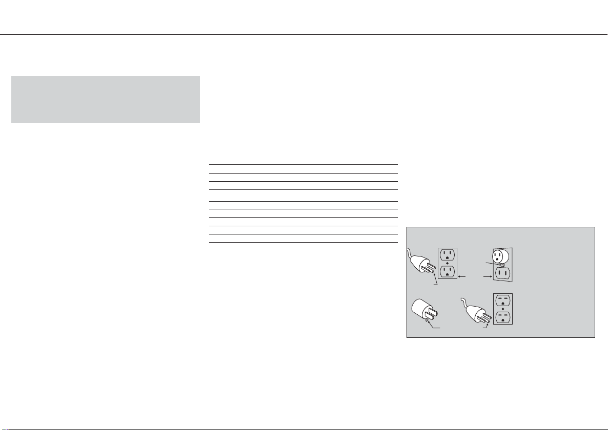
25. Grounding instructions. This tool should be grounded while
in use to protect the operator from electric shock. The tool is
equipped with a 3-conductor cord and 3-prong grounding type
plug to fit the proper grounding type receptacle. The green (or
green and yellow) conductor in the cord is the grounding wire.
Never connect the green (or green and yellow) wire to a live terminal. If your unit is for use on less than 150 V, it has a plug that looks
like that shown in sketch (A) in Figure «Grounding Methods». If it is
for use on 150 to 250 V, it has a plug that looks like that shown in
sketch (D). An adapter, see sketches (B) and (C), is available for
connecting sketch (A) type plugs to 2-prong receptacles. The
green-colored rigid ear, lug, or the like, extending from the adapter
must be connected in a permanent ground, such as a properly
grounded outlet box. No adapter is available for a plug as
in sketch (D).
GROUNDING METHODS
metal screw
cover of grounded
outlet box
grounding pin
26. Extension Cords. Use only 3-wire extension cords that have
3-prong grounding-type plugs and 3-pole receptacles that accept
the tool’s plug. Replace or repair damaged cords.
Please read and take note of these precautions before you use the
tool/machine and always keep this safety precautions with the
tool.
(A)
grounding
grounding pin
means
(C) (D)
(B)
shown
SAVE THESE INSTRUCTIONS
Printed: 07.07.2013 | Doc-Nr: PUB / 5071017 / 000 / 00
Page 3
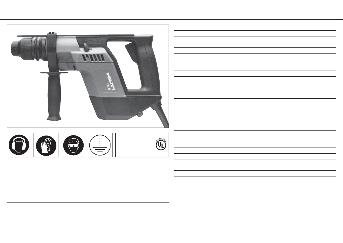
Hilti TE 5 Rotary Hammer
This Product is Listed
by Underwriters
Laboratories Inc.
and bears the Mark:
Always wear ear
protectors.
Always wear protective gloves.
Always wear safety
glasses.
Protective earthing
Technical data
Power input: 500 W
Voltage: 115 V
Current input: 4.6 A
Frequency: 50–60 Hz
Weight: 2.8 kg / 6.2 Ibs
Speed under load: 0–800 r.p.m.
Hammering speed under load: 0–4000 blows per minute
Single impact energy: 2.0 joules / 1.5 ft-lb
Drill bit diameter range: 5–20 mm (3/16″–3/4″) dia. in concrete
Recommended range: 5–10 mm (3/16″–3/8″) dia.
Drilling performance in B35 concrete: 8/150 mm (
(1.46 in.3) = 480 mm/min.
Drill bits in standard programme:
TE-C drill bits 4–16 mm (
TE-C-S drill bits 18 mm / 20 mm (5/8″/3/4″) dia.
TE-C-HB forming bit 10–24 mm (3/8″–1″) dia.
Chuck TE-C
Carbon brushes with automatic cut-out
Protection class I (grounded tool)
Slip-type clutch as protection against motor overloading
Sealed against dust, permanent lubrication (maintenance free)
Variable speed control switch with infinite regulation
Reversing switch
Adjustable side handle with depth gauge
Automatic hammering cut-out when idling
Setting lever for hammer drilling/rotary drilling only
Connections for dust removal system
Right of technical modifications reserved.
5
/16″/6″) dia.= 24 cm3/min.
5
/32″–5/8″) dia.
Accessories and kit for Hilti TE 5 rotary hammer:
Hilti lubricant spray, TE 5-DRS dust removal system, key-type chuck, quickrelease chuck case or cardboard box
Before starting to work, please read the enclosed safety precautions.
Printed: 07.07.2013 | Doc-Nr: PUB / 5071017 / 000 / 00
Please refer to the respective regulations of your trade association and the
enclosed safety precautions!
Page 4

1
Before beginning work:
1. Check that the electric supply corresponds to the information on the rating
plate.
2. The TE5 is 3 wire grounded.
3. Do not apply excessive pressure to
the TE 5 – hammering/impact power
will not be increased. Simply position
and guide the TE5.
4. Check that the direction of rotation is
set correctly.
Before starting to work, please read
the enclosed safety precautions.
Cleaning the drill bit
The chuck is not included in the
machine's lubrication system. The drill
bit connection end should therefore be
cleaned at regular intervals and spray-
ed sparingly with Hilti lubricant spray,
which is available as an accessory.
Start-up time at low temperatures
Start-up time can be reduced by jolting
the drill bit against the work surface
when switching on.
Operation:
Fig.1: Inserting the drill bit
Turn chuck towards
insert the drill bit, turning it until the
drive grooves engage and it can be
pushed in fully. Lock the chuck by turning it towards the()symbol.
Fig.2: Hammer drilling
For hammer drilling in concrete masonry and natural stone, adjust the setting
lever to the hammer drilling position (-
) symbol).
Printed: 07.07.2013 | Doc-Nr: PUB / 5071017 / 000 / 00
()
symbol and
Drilling without hammering action
Adjust the setting lever to the rotary
drililng position ( symbol). When
set to this position, only the rotary
action is transmitted to the drill bit.
Fig. 3: Reversing switch
The desired direction of rotation for
screwdriving can be selected with the
reversing switch. For counter-clockwise rotation, the setting lever must be
in the rotary drilling position (no hammering action). Counter-clockwise
rotation should only be used for short
periods.
Fig. 4: Changing the chuck
Pull the sleeve forwards to remove the
complete chuck. To replace the chuck,
pull the sleeve forwards and hold it in
that position. Slide the chuck onto the
guide as far as it will go and release the
sleeve. Turn the chuck until the balls
engage and the sleeve snaps back into
position.
Fig. 5: Side handle / depth gauge
The side handle can be turned through
360° and locked in the desired position. Release the side handle by turning
it counter-clockwise, set the desired
drilling depth with the depth gauge and
then lock the side handle by turning it
clockwise.
Note: When the key-type chuck is fitted, the hammering action cuts out
automatically (rotary drilling only).
Inserting the cylindrical connection
end: Open the key-type chuck to the
required diameter, insert the drill bit as
far as it will go and tighten using the
key. The key-type chuck can also be
used for counter-clockwise rotation.
Dust removal:
All TE 5 rotary hammer drills can be
equipped with a dust removal system
(see following pages), which can be
attached to the TE 5 quickly and simply.
2
Servicing:
Electric tools must conform to the
applicable safety regulations. Servicing
must only be carried out by a trained
electrical specialist. The use of original
Hilti spare parts ensures optimal safety.
3
4
5
Page 5

Hilti TE 5-DRS Dust Removal System
Technical data
Power input: max.60 W
Suction capacity: 500 I/min.
Weight: 0.8 kg /1.8 Ibs
Maximum stroke: 112 mm / 41/4″
Suitable TE-C drill bits (It/cm): 5–17.5 mm (
Drill bit working length: 50–100 mm (2″–4″)
Contact pressure: 15–25 N (3.4–5.6 Ibs)
Dust container capacity: 130 holes –
Dust container regeneration cycles: up to 100 cycles
Extraction heads 5–12.0 mm (
Built-in extraction fan
Dust container incorporating folded filter
Depth gauge
Length adjustment
Plug-in drive coupling for extraction fan
3
10–18 cm (4″–6″)
6mm(
75 holes –
8mm(5/16″) dia. / 30 mm (11/8″) deep
20 holes –
12 mm (1/2″) dia. / 50 mm (2″) deep
12–17.5 mm (1/2″–9/16″) dia. (D17.5)
/16″–9/16″) dia. /
1
/4″) dia. / 28 mm (11/16″) deep
3
/16″–1/2″) dia. (D12)
Kit supplied with TE 5-DRS: Case or cardboard box, cover for dust container,
D12 extraction head, D17.5 extraction head
TE 5-DRS accessories: Dust container with cover and folded filter
Printed: 07.07.2013 | Doc-Nr: PUB / 5071017 / 000 / 00
Riqht of technical modifications reserved
Page 6

5
Assembly/disassembly
Fig.1+2: Drive coupling principle
The built-in extraction fan in the dust
removal module is driven by the TE5
motor via a plug-in coupling. The teeth
on the rotor shaft () grip the toothed
plug-in sleeve () on the dust removal
module.
Fig.3/4: Assembling the dust removal
module
Fig.3: Open the cover () on the under-
side of the housing endcap and engage
it in the open position.
Fig.4: Press in the lockbutton ()onthe
dust removal module and slide the module into the guides on the housing and
housing endcap. The drive coupling
engages automatically. Release the
lockbutton. The lockbutton must return
to its original position (not pressed in).
Only then is the dust removal module
securely attached to the TE5.
Fig.5: Disassembling the dust
removal module
Press in the lockbutton () on the dust
removal module and pull the module
downwards. Close the cover ()onthe
underside of the motor endcap (protects
from dirt and dust).
Operation
Fig.6: Adjustment of drilling depth
(depth gauge)
Open the locking lever () and move
stop () to the desired drilling depth.
Close the locking lever (). Drill test
holes if an exact drilling depth is
Printed: 07.07.2013 | Doc-Nr: PUB / 5071017 / 000 / 00
required for anchors. Clean out the
anchor holes according to the instructions for the anchors used.
Fig. 7: Length adjustment (stroke)
Length adjustment is normally set for
TE-C drill bits I
responds to a drill bit working length of
100 mm (4″). For shorter drill bits, open
the locking lever () and press the
extraction head against the wall, sliding
it back until it is flush with the point of
the drill bit. Close the locking lever ().
Stop for length adjustment can be
removed 훽. To do so, pull out the stop
at the connection end. Grip the stop bar
at the front, at the suction head end, and
pull it out upwards.
Fig. 8: Changing the extraction head
The small extraction head has been
optimized for use with 5–12 mm (3/16″–
1
/2″) dia. TE-C drill bits. The larger extraction head must be used for 12–17.5 mm
(1/2″–9/16″) dia. drill bits. To remove the
extraction head, press in the rib ()on
the back of the head and pull the head
upwards. The extraction head is
replaced by inserting it from above and
pressing down until it engages. Small
diameter drill bits may also be used with
the larger extraction head but optimum
dust removal performance will not be
achieved.
Fig. 9: Emptying the dust container
Before removing the dust container,
hold the TE5 horizontal and switch it on
briefly. All remaining dust which has
accumulated in the dust module is then
drawn into the dust container. Press in
both buttons () on each side of the
dust container and pull it down and
t =15cm(6″), which cor-
away from the machine. Tap the container lightly when emptying. Replace
the container by sliding it in from below
until a definite click is heard. When using
a new dust container, first remove the
cover and then slide it into position as
described above.
Cleaning
The dust removal system should be
cleaned only by using compressed air
and a cleaning cloth (no water, oil,
grease or cleaning agents).
1 2
3
4
6
7
8
9
Page 7

Warranty
Hilti warrants that the tool supplied is
free of defects in material and workmanship. This warranty is valid as long
as the tool is operated and handled
correctly, cleaned and serviced properly and in accordance with the Hilti
Operating Instructions, all warranty
claims are made within 12 months from
the date of the sale (invoice date), and
the technical system is maintained.
This means that only original Hilti consumables, components and spare
parts may be used in the tool.
This warranty provides the freeofcharge repair or replacement of
defective parts only. Parts requiring
repair or replacement as a result of normal wear and tear are not covered by
this warranty.
Under no circumstances will Hilti be
obligated for direct, indirect, incidental or consequential damages,
losses or expenses in connection
with, or by reason of, the use of, or
inability to use the tool for any purpose. Hilti specifically excludes the
implied warranties of merchantability and fitness for a particular purpose.
For repair or replacement, send the tool
and/or related parts immediately upon
discovery of the defect to the address
of the local Hilti marketing organization
provided.
This constitutes Hilti's entire obligation
with regard to warranty and supersedes all prior or contemporaneous
comments and oral or written agreernents concerning warranties.
Printed: 07.07.2013 | Doc-Nr: PUB / 5071017 / 000 / 00
 Loading...