

Page 1

TE16 / TE16-C /
TE16-M
*287428*
287428
Bedienungsanleitung de
Operating instructions en
Mode d’emploi fr
Istruzioni d’uso it
Gebruiksaanwijzing nl
Manual de instruções pt
Manual de instrucciones es
Brugsanvisning da
Käyttöohje fi
Bruksanvisning no
Bruksanvisning sv
Οδηγιες χρησεως
el
Kasutusjuhend et
Lieto‰anas pamÇc¥ba lv
Page 2
1
1
2
3
5
TE 16-M
4
6
7
TE 16-C
Page 3

2
3
3
3
2
2
1
-M
6
1
E
T
4
4
4
5
5
1
M
-
6
1
E
T
4
3
6
1
1
6
2
6
5
4
1
( ) ( )
( ) ( ) ( ) ( )
7
8
( ) ( )
( ) ( )
7 8
2/4
( ) ( )
1
( ) ( )
2
1
3
Page 4

9 10
1
3
4
11 12
TE 16-M
1
2
L
R
Page 5

13
en
It is essential that the operating
instructions are read before the tool is
operated for the first time.
Always keep these operating instructions
together with the tool.
Ensure that the operating instructions are
with the tool when it is given to other
persons.
TE 16/-C/-M rotary hammer
1. General information
1.1 Safety notices and their meaning
-CAUTION-
Draws attention to a potentially dangerous situation
that could lead to minor personal injury or damage
to the equipment or other property.
-NOTE-
Draws attention to instructions and other useful information that help the user to employ the product efficiently.
Contents Page
1. General information 13
2. Description 14
3. Tools and accessories 14
4. Technical data 15
5. Safety precautions 16
6. Before use 18
7. Operation 19
8. Care and maintenance 21
9. Troubleshooting 22
10. Disposal 23
11. Warranty 23
12. EC declaration of conformity 24
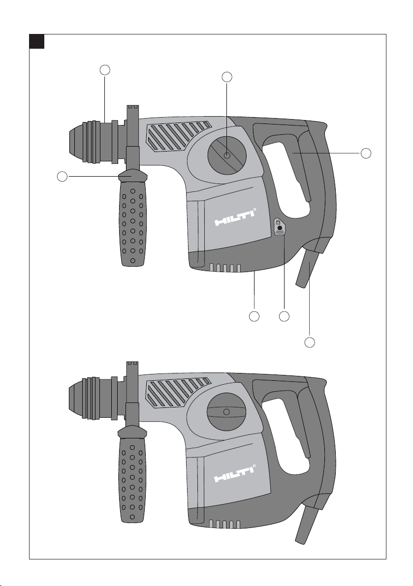
Operating controls and parts
Chuck
Function selector switch
Control switch
Forwards/reverse switch
Side handle with depth gauge
Theft protection system
(accessory for TE 16-M available as option)
Supply cord
These numbers refer to the corresponding illustrations. The illustrations can be found on the fold-out
cover pages. Keep these pages open while studying
the operating instructions.
In these operating instructions, the TE 16, TE 16-C or
TE 16-M is referred to as "the tool".
Location of identification data on the tool
The type designation can be found on the rating plate
and the serial number on the side of the motor housing.
Make a note of this data in your operating instructions
and always refer to it when making an enquiry to your
Hilti representative or service department.
Type:
Serial No.:
1.2 Pictograms
Warning signs
Obligation signs
Wear ear
protection
Wear
protective
gloves
Wear
breathing
protection
Wear eye
protection
Read the
operating
instructions
before use.
Symbols
General
warning
Warning:
electricity
Warning:
hot surface
Wear a
hard hat
Page 6

14
en
2. Description
The tool is an electrically powered rotary hammer with
pneumatic hammering mechanism. The tool is intended
for professional use.
2.1 Use of the tool as intended
The tool is designed for drilling in concrete and masonry.
The tool may also be used for light chiseling work on
masonry and for finishing concrete surfaces.
The working environment may be on a construction
site or in a workshop and the tool may be used for renovation, conversion or new building work.
The tool may be operated only when connected to a
power supply providing a voltage and frequency in
compliance with the information given on its rating
plate.
Changes or modifications to the tool are not permissible.
To avoid the risk of injury, use only original Hilti accessories and additional equipment. Observe the information printed in the operating instructions concerning operation, care and maintenance. The tool and its
ancillary equipment may present hazards when used
incorrectly by untrained personnel or when used not
as directed.
2.2 Chucks
– TE-C (SDS plus) chuck
– TE-T (SDS top) chuck
2.3 Switches
2.3.1 Switches on the TE 16
Speed control switch for smooth starting.
Function selector switch for:
– Drilling without hammering
– Hammer drilling
2.3.2 Switches on the TE 16-C
Speed control switch for smooth starting.
Function selector switch for:
– Drilling without hammering
– Hammer drilling
– Chisel adjustment (12 positions)
– Chiseling
2.3.3 Switches on the TE 16-M
Speed control switch for smooth starting.
Function selector switch for:
– Drilling without hammering 2
– Drilling without hammering 1
– Hammer drilling
– Chisel adjustment (12 positions)
– Chiseling
2.4 Grips
– Adjustable side handle with depth gauge
– Vibration-absorbing grip
2.5 Protective devices
– Mechanical slip clutch
2.6 Lubrication
– Oil lubrication
2.7 Items supplied as standard
– The electric tool
– TE-C or TE-T chuck
– Side handle with depth gauge
– Operating instructions
–Toolbox
– Cleaning cloth
– Grease
– Dust shield
3. Tools and accessories
TE 16 TE 16-C TE 16-M
Chuck TE-C (SDS plus) TE-C (SDS plus) TE-C (SDS plus)
Chuck TE-T (SDS top) TE-T (SDS top) TE-T (SDS top)
Hammer drill bits 5–25 mm dia.
Percussion core bits 66–90 mm dia. (TE-C)
50–90 mm dia. (TE-T)
Formwork and
installation drill bits 10–35 mm dia. (TE-C)
Lightweight percussion
core bits for masonry 25–68 mm dia. (TE-C)
Multi-purpose hole saws 35–105 mm dia.
(hex. connection end)
Page 7

15
en
Chisels Pointed, flat and shaped chisels with TE-C or TE-T
connection end
Setting tools Setting tools with TE-C or TE-T connection end
Quick-release chucks Quick-release chucks 282341 and 282342 for wood
and metal drill bits with cylindrical or hex. connection end
Wood drill bits 5–25 mm dia.
Metal drill bits up to 13 mm dia.
Stepped drill bits for metal 3–8 mm dia.
(2nd gear)
8–13 mm dia.
(1st gear)
(hex. connection end)
Mixing paddles for 80–150 mm dia.
non-inflammable substances mixing paddles
with cylindrical shank
Dust removal system TE DRS-S
Theft protection system
(available as option) TPS
4. Technical data
Tool TE 16 TE 16-C TE 16-M
Rated power input 800 W 800 W 850 W
Rated voltage/rated 100 V / 8,2 A 100 V / 8,2 A 100 V / 11,0 A
current input 110 V / 7,3 A 110 V / 7,3 A 110 V / 10,0 A
110–127 V / 6,8 A 110–127 V / 6,8 A 110–127 V / 10,0 A
120 V / 6,8 A 120 V / 6,8 A 120 V / 9,2 A
220 V / 3,8 A 220 V / 3,8 A 220 V / 5,0 A
230 V / 3,6 A 230 V / 3,6 A 230 V / 4,8 A
240 V / 3,5 A 240 V / 3,5 A 240 V / 4,6 A
Mains frequency 50–60 Hz 50–60 Hz 50–60 Hz
Weight of tool 3.8 kg 3.85 kg 4.05 kg
Dimensions (L xWxH) 360 x 90 x 210 mm 360 x 90 x 210 mm 370 x 90 x 210 mm
Drilling speed without
hammering, position 2 1100 r.p.m.
Drilling speed without
hammering, position 1 750 r.p.m. 750 r.p.m. 750 r.p.m.
Hammer drilling speed 750 r.p.m. 750 r.p.m. 750 r.p.m.
Single impact energy 3.2 J 3.2 J 3.2 J
Chuck TE-C (SDS plus)/TE -T (SDS top)
Drilling dia. range in concrete/
masonry (hammer drilling) 5–28mm dia.
Percussion core bits 66–90 mm dia.
Drilling dia. range with drill
bits for wood 5–20 mm dia.
Drilling dia. range with drill
bits for metal max. 13 mm dia.
Drilling dia. range in
medium-hard concrete 16 mm dia./72 cm3/min
Double insulated
(in accordance with EN 50144) Protection class II Z
Mechanical slip clutch
Page 8

16
5. Safety precautions
5.1 Basic information concerning safety
CAUTION: To avoid the risk of electric shock, injury or
fire, the following basic safety precautions must always
be observed when using electric tools.
Read all safety precautions and instructions before
using this tool.
5.2 Safety precautions at the workplace
● Ensure that the workplace is well lit.
● Ensure that the workplace is well ventilated.
● Keep the workplace tidy. Objects which could cause
injury should be removed from the working area.
Untidiness at the workplace can lead to accidents.
● Secure the workpiece. Use clamps or a vice to hold
the workpiece in place. The workpiece is thus held
more securely than by hand and both hands remain
free to operate the tool.
● Wear eye protection.
● Wear breathing protection if the work creates dust.
● Wear suitable working clothing. Do not wear loose
clothing, loose long hair or jewelry as it can become
caught up in moving parts. Wear suitable headgear
if you have long hair.
● It is recommended that protective gloves and non-
slip shoes are worn when working outdoors.
● Keep children and other persons away from the work-
ing area.
● Do not allow other persons to tamper with the tool
or the supply cord.
● Avoid unfavorable body positions. Work from a secure
stance and stay in balance at all times.
● Connect the dust extraction system. Check that this
system is connected and used correctly.
● To avoid tripping and falling when working, always
lead the supply cord, extension cord and dust extraction hose away to the rear.
● Concealed electric cables or gas and water pipes pre-
sent a serious hazard if damaged while you are working. Accordingly, check the area in which you are
working beforehand (e.g. using a metal detector).
External metal parts of the tool may become live, for
example, when an electric cable is drilled into inadvertently.
5.3 General safety precautions
● Use the right tool for the job. Do not use the tool for
purposes for which it was not intended. Use the tool
only as directed and when it is in faultless condition.
● Avoid contact with rotating parts.
● Use only the original accessories or ancillary equip-
ment listed in the operating instructions. Use of accessories or items of ancillary equipment other than
those listed in the operating instructions may present a risk of personal injury.
● Take the influences of the surrounding area into
account. Do not expose the tool to rain or snow and
do not use it in damp or wet conditions. Do not use
the tool where there is a risk of fire or explosion.
● Keep the grips clean, dry and free from oil and grease.
● Do not overload the tool. It will work more efficiently
and more safely within its intended performance
range.
● Always hold the tool securely with both hands on the
grips provided.
Vibration absorbing grip
and side handle
Interference immunity in accordance with EN 55014-2
Radio and television
interference suppression in accordance with EN 55014-1
Noise and vibration information (measured in
accordance with EN 50144):
Typical A-weighted sound
power level (LwA): 102 dB (A)
Typical A-weighted sound
power level (LpA): 89 dB (A)
Wear ear protection!
Typical weighted vibration
at the grips 9,5 m/s
2
9 m/s
2
Right of technical changes reserved!
en
Page 9

17
en
● When not in use, the tool must be stored in a dry
place, locked up or out of reach of children.
● Avoid unintentional starting. Never keep a finger on
the on/off switch when carrying the tool when it is
connected to the electric supply. Check that the on/
off switch is in the "off" position before plugging the
supply cord into the electric socket.
● Switch the tool on only once it has been brought into
the working position close to the workpiece.
● Unplug the tool when it is not in use, during pauses
between work, before maintenance and before changing insert tools.
● Switch the tool off before transporting it.
● Take care of your insert tools. You will be able to work
more efficiently and more safely if the insert tools
are kept sharp and clean. Observe the instructions
concerning lubrication and changing insert tools.
● Check that moving parts function correctly without
sticking and that no parts are damaged. All parts
must be fitted correctly and fulfill all conditions necessary for correct operation of the tool.
● Check the tool for possible damage. Protective devices
and any parts that may have suffered slight damage
should be checked for correct operation and functionality before further use. Damaged safety devices
or other damaged parts must be replaced or repaired
properly by an authorized repair workshop unless
otherwise indicated in the operating instructions.
5.3.1 Mechanical hazards
● Observe the instructions concerning care and main-
tenance.
● Ensure that the insert tools used are equipped with
the appropriate connection end system and that they
are properly fitted and secured in the chuck.
5.3.2 Electrical hazards
● Protect yourself against electric shock. Avoid body
contact with earthed/grounded objects, e.g. pipes,
radiators, cookers and fridges.
● Check the condition of the supply cord and its plug
connections and have it replaced by a qualified electrician if damage is found. Check the condition of the
extension cord and replace it if damage is found.
● Check the condition of the tool and its accessories.
Do not operate the tool or its accessories if damage
is found, if the tool is incomplete or if its controls
cannot be operated faultlessly.
● Do not touch the supply cord in the event of it suf-
fering damage while working. Disconnect the supply cord plug from the socket.
● Damaged or faulty switches must be replaced at a
Hilti service center. Do not use the tool if its switch
is inoperative.
● Have the tool repaired only by a trained electrical
specialist (Hilti service center) using original Hilti
spare parts. Failure to observe this point may result
in risk of accident to the user.
● Electrostatic discharge is possible at any time.
● Do not use the supply cord for purposes for which
it is not intended. Never carry the tool by the supply
cord and never pull the plug out of the socket by
pulling the supply cord.
● Do not expose the supply cord to heat, oil or sharp
edges.
● When working outdoors, use only extension cords
that are approved and correspondingly marked for
this type of use.
● In the event of a power failure, switch the tool off
and unplug the supply cord.
● Avoid using extension cords with multiple sockets
and the simultaneous use of several tools connected
to one extension cord.
● Never operate the tool when it is dirty or wet. Dust
(especially dust from conductive materials) or dampness adhering to the surface of the tool may, under
unfavorable conditions, present a risk of electric
shock. Dirty or dusty electric tools should thus be
checked at a Hilti service center at regular intervals,
especially if used frequently for working on conductive materials.
5.3.3 Thermal hazards
● The insert tool may become hot during use. Wear
protective gloves when changing insert tools.
5.3.4 Dust
● Breathing protection must be worn when the tool is
used without a dust removal system for work that
creates dust.
Warning:
hot surface
Wear
protective
gloves
Wear
breathing
protection
Page 10

18
en
5.4 Requirements to be met by users
● The tool is intended for professional use.
● The tool may be operated, serviced and repaired only
by authorized, trained personnel. This personnel
must be informed of any special hazards that may
be encountered.
● Always concentrate on the job you are doing. Pro-
ceed carefully and do not use the tool if your full
attention is not on the job.
● Exercise your fingers during pauses between work
to improve the blood circulation in your fingers.
5.5 Personal protective equipment
The user and any other persons in the vicinity must
wear suitable eye protection, a hard hat, ear protection
and protective gloves when the tool is in use. Breathing protection must be worn if no dust removal system is used.
6. Before use
6.1 Use of extension cords
Use only extension cords of a type approved for the
application and with conductors of adequate cross section. Failure to observe this point may cause the tool
to lose power and the extension cord may overheat.
Check the extension cord for damage at regular intervals. Replace damaged extension cords.
Recommended minimum conductor cross section and
max. extension cord lengths:
Mains voltage Conductor cross section AWG
1.5 mm22.0 mm22.5 mm23.3 mm214 12
100 V – 30 m – 50 m – –
110–120 V 20 m 30 m 40 m 50 m 75 ft 125 ft
220–240 V 50 m – 100 m – – –
Do not use extension cords with 1.25 mm
2
or 16 AWG conductor cross sec-
tions.
Use of extension cords outdoors
When working outdoors use only extension cords that
are correspondingly marked and approved for outdoor
use.
6.2 Use of a generator or transformer
This tool may be powered by a generator or transformer
which fulfils the following conditions:
– AC voltage, output power at least 2600 W.
– The operating voltage must be within +5 % and
–15 % of the rated voltage at all times.
– Frequency range 50–60 Hz, never above 65 Hz.
– Automatic voltage regulation with starting boost.
Never operate other tools or appliances from the generator or transformer at the same time. Switching other
tools or appliances on and off may cause undervoltage and/or overvoltage peaks, resulting in damage to
the electric tool.
6.3 Fitting the side handle
1. Unplug the tool from the mains socket.
2. Release the side handle clamping band by turning
the handle in a counter-clockwise direction.
3. Fit the side handle clamping band over the chuck
and onto the cylindrical section at the front end of
the tool.
4. Pivot the side handle into the desired position.
5. Tighten the side handle securely to prevent inad-
vertent movement.
Wear ear
protection
Wear
protective
gloves
Wear
breathing
protection
Wear eye
protection
Wear a
hard hat
Page 11

19
en
7. Operation
CAUTION: In the event of the drill bit sticking, the tool
will pivot about its own axis.
Always use the tool with the side handle fitted and hold
it securely with both hands applying an opposing torque
so that the clutch releases in the event of the drill bit
sticking.
Use a vice or clamp to secure loose workpieces.
7.1 Preparing the tool for use
7.1.1 Adjusting the depth gauge
1. Release the side handle clamping mechanism by
turning the handle in a counter-clockwise direction.
2. Pivot the side handle into the desired position.
3. Adjust the depth gauge to the desired drilling depth
"X".
4. Tighten the side handle securely by turning the handle in a clockwise direction.
7.1.2 Fitting the insert tool (TE-C)
1. Unplug the supply cord from the mains socket.
2. Check that the connection end of the insert tool is
clean and lightly greased. Clean it and grease it if
necessary.
3. Check that the sealing lip of the dust shield is clean
and in good condition. Clean the dust shield if necessary or replace it if the sealing lip is damaged.
4. Push the connection end of the insert tool into the
chuck and, while applying slight pressure, rotate the
insert tool until it engages in the guide grooves.
5. Push the insert tool further into the chuck until it is
heard to engage.
6. Check that the insert tool has engaged correctly (pull
by hand).
7.1.3 Removing the insert tool (TE-C)
1. Unplug the supply cord from the mains socket.
2. Open the chuck by pulling back the locking sleeve.
3. Pull the insert tool out of the chuck.
7.1.4 Fitting the insert tool (TE-T)
-NOTE-
Remove the depth gauge from the side handle in order
to avoid injury.
1. Unplug the supply cord from the mains socket.
2. Check that the connection end of the insert tool is
clean and lightly greased. Clean it and grease it if
necessary.
3. Check that the sealing lip of the dust shield is clean
and in good condition. Clean the dust shield if necessary or replace it if the sealing lip is damaged.
4. Turn the chuck locking ring toward the
()
sym-
bol.
5. Push the insert tool into the chuck as far as it will go.
6. Rotate the insert tool until it is heard to engage.
7. Turn the chuck locking ring toward the ()symbol.
8. Check that the insert tool has engaged correctly (pull
by hand).
7.1.5 Removing the insert tool (TE-T)
-NOTE-
Remove the depth gauge from the side handle in order
to avoid injury.
1. Unplug the supply cord from the mains socket.
2. Turn the chuck locking ring toward the
()
sym-
bol.
3. Pull the insert tool out of the chuck.
4. Turn the chuck locking ring toward the ()symbol.
7.1.6 Removing the chuck (TE-C und TE-T)
-NOTE-
Remove the depth gauge from the side handle in order
to avoid injury.
1. Unplug the supply cord from the mains socket.
2. Pull the retaining ring on the chuck toward the front
and hold it in this position.
3. Pull the chuck away from the tool toward the front.
7.1.7 Fitting the chuck (TE-C und TE-T)
-NOTE-
Remove the depth gauge from the side handle in order
to avoid injury.
The chuck must be open
()
.
1. Unplug the supply cord from the mains socket.
2. Grip the sleeve around the base of the chuck and pull
it forward. Hold it in this position.
3. Push the chuck onto the guide tube on the tool and
release the sleeve.
4. Turn the chuck until it is heard to engage.
-CAUTION-
● The insert tool may become hot dur-
ing use.
● There is a risk of burning the hands.
● Wear protective gloves when chang-
ing insert tools.
Page 12

20
en
7.2 Operating the tool
7.2.1 Activating the tool (theft protection system)
(TE 16-M) (accessory available as option)
Please refer to the operating instructions for the TPS
theft protection system.
1. Plug the supply cord of the tool into the mains socket.
The yellow theft protection indicator blinks. (The tool
is now under power and ready for activation by contactless communication with a valid electronic activation key.)
2. Bring the tool within range of the activation key
(approx. 50–70 cm). The tool is activated and ready
for use as soon as the yellow theft protection indicator lamp no longer lights. (The system is designed
so that the activation key for the tool normally doesn't have to be taken out of the trouser pocket.)
-NOTE-
The tool remains activated and ready for use as long
as it is connected to the mains supply
7.2.2 Drilling without hammering,
position (2 ) (TE 16-M)
1. Engage the function selector switch in the (2 )
position. Do not operate the function selector switch
while the motor is running.
2. Adjust the side handle to the desired position and
check that it is fitted and secured correctly.
3. Plug the supply cord into the mains socket.
4. Position the tip of the drill bit at the point where the
hole is to be drilled.
5. Press the control switch slowly. Begin drilling at low
speed, increasing speed only after the drill bit has
become centered in the hole.
6. Press the control switch fully to continue drilling at
full power.
7. Do not apply excessive pressure to the tool. This will
not increase its hammering power. Lower contact
pressure increases the life of the insert tool.
7.2.3 Drilling without hammering, position
(
/ 1
) (TE 16/TE 16-C /TE 16-M)
1. Engage the function selector switch in the
(
/ 1
) position. Do not operate the func-
tion selector switch while the motor is running.
2. Adjust the side handle to the desired position and
check that it is fitted and secured correctly.
3. Plug the supply cord into the mains socket.
4. Position the tip of the drill bit at the point where the
hole is to be drilled.
5. Press the control switch slowly. Begin drilling at low
speed, increasing speed only after the drill bit has
become centered in the hole.
6. Press the control switch fully to continue drilling at
full power.
7. Do not apply excessive pressure to the tool. This will
not increase its hammering power. Lower contact
pressure increases the life of the insert tool.
7.2.4 Hammer drilling ( )
(TE 16/TE 16-C/TE 16-M)
1. Engage the function selector switch in the
()position. Do not operate the function
selector switch while the motor is running.
2. Adjust the side handle to the desired position and
check that it is fitted and secured correctly.
3. Plug the supply cord into the mains socket.
4. Position the tip of the drill bit at the point where the
hole is to be drilled.
5. Press the control switch slowly. Begin drilling at low
speed, increasing speed only after the drill bit has
become centered in the hole.
6. Press the control switch fully to continue drilling at
full power.
7. Do not apply excessive pressure to the tool. This will
not increase its hammering power. Lower contact
pressure increases the life of the insert tool.
8. When drilling through-holes, avoid spalling by reducing drilling speed shortly before breaking through.
-NOTE-
When working at low temperatures:
The hammering mechanism begins to operate only
when the tool has reached a minimum operating temperature.
Press the tip of the drill bit briefly against the work surface while the tool is running. Repeat this procedure if
necessary. The hammering mechanism will begin to
operate when the tool reaches the minimum operating
temperature.
7.2.5 Chiseling (
/
)
(TE 16-C/TE 16-M)
-NOTE-
The chisel can be locked in 12 different positions (in
30° increments). Flat and shaped chisels can thus
always be brought into the optimum position for the
job on hand.
-CAUTION-
● Drilling may cause splintering of the
material.
● Splinters may cause injury to parts
of the body and eyes.
● Wear eye protection, protective gloves
and breathing protection if no dust
removal system is used.
-CAUTION-
● The tool and the drilling operation
emit noise.
● Excessive noise may damage the
hearing.
● Wear ear protection.
Page 13

21
en
Chisel position adjustment
1. Engage the function selector switch in the position
( ). Do not operate the function selector switch
while the motor is running.
2. Adjust the side handle to the desired position and
check that it is fitted and secured correctly. (When
chiseling, the tool may also be held at the section of
the housing behind the chuck.)
3. Adjust the chisel to the desired position.
-CAUTION-
Do not work with the tool when the function selector
switch is in this position.
Locking the chisel
1. Engage the chisel selector switch in the ( )
position. Do not operate the function selector switch
while the motor is running.
Chiseling ( )
1. Plug the supply cord into the mains socket.
2. Position the tip of the chisel at the desired position
on the work surface.
3. Press the control switch fully.
7.2.6 Forwards/reverse rotation
-CAUTION-
Do not operate the forwards/reverse switch while the
motor is running.
1. Turn the switch to the forwards ("R") or reverse ("L")
position.
8. Care and maintenance
Unplug the supply cord from the mains socket.
8.1 Care of insert tools
Clean off dirt and dust deposits and protect your insert
tools from corrosion by wiping them from time to time
with an oil-soaked rag.
8.2 Care of the electric tool
The outer casing of the tool is made from impact-resistant plastic. Sections of the grip are made from a synthetic rubber material.
Never operate the tool when the ventilation slots are
blocked. Clean the ventilation slots carefully with a dry
brush. Do not permit foreign objects to enter the interior of the tool. Clean the outside of the tool at regular
intervals with a slightly damp cloth. Do not use a spray,
steam pressure cleaning equipment or running water
for cleaning. This may negatively affect the electrical
safety of the tool. Always keep the grip surfaces of the
tool free from oil and grease. Do not use cleaning agents
containing silicone.
8.3 Maintenance
Check all external parts of the tool for damage at regular intervals and check that all controls operate faultlessly. Do not operate the tool if parts are damaged or
when the controls do not function faultlessly. If necessary, your electric tool should be repaired at a Hilti
repair center.
Repairs to the electrical section of the tool may be carried out only by trained electrical specialists.
8.4 Checks after care and maintenance
After carrying out care and maintenance on the tool,
check that all protective equipment has been refitted
and that all parts function faultlessly.
Page 14

22
en
9. Troubleshooting
Fault
The tool doesn't start.
No hammering action.
The tool does not
achieve full power.
Drill bit doesn't rotate.
The drill bit cannot be
released from the chuck.
The drill bit makes no
progress.
Possible cause
Fault in mains supply.
Supply cord or plug defective.
Control switch defective.
The tool is not activated.
(TE16-M with theft protection system)
The tool is too cold.
The function selector switch is set to
rotary drilling.
Extension cord with inadequate cross
section used.
Control switch not fully pressed.
Function selector switch not
engaged.
Chuck sleeve not pulled back fully.
Side handle not correctly fitted or
moved out of place.
The forwards/reverse switch is set to
reverse rotation.
Remedy
Plug in another electric appliance and
check whether it works.
Have the cord checked and, if necessary, replaced by an electrical specialist.
Have it checked and, if necessary,
replaced by an electrical specialist.
Activate the tool with the activation
key.
Allow the tool to warm up to the minimum operating temperature.
(See "Operation".)
Set the function selector switch to hammer drilling.
Use an extension cord with adequate
cross section. (See "Before use".)
Press the control switch as far as it will
go.
After rotation has stopped, move the
function selector switch until it
engages.
Pull the chuck sleeve back as far as it
will go and remove the insert tool.
Release the side handle and reposition it
correctly so that the clamping band and
side handle are engaged in the groove.
(see 6.3)
Set the switch to forwards rotation.
Page 15

23
en
11. Warranty
Hilti warrants that the product supplied is free of defects
in material and workmanship. This warranty is valid as
long as the product is operated and handled correctly,
cleaned and serviced properly and in accordance with
the Hilti operating instructions, all warranty claims are
made within 12 months (unless other mandatory national
regulations prescribe a longer minimum period) from
the date of sale (invoice date) and the technical system is maintained, i.e. only original Hilti consumables,
accessories and spare parts are used with the product.
This warranty provides the free-of-charge repair or
replacement of defective parts only. Parts requiring
repair or replacement as a result of normal wear and
tear are not covered by this warranty.
Additional claims are excluded, unless mandatory
national regulations prohibit such exclusion. In particular, Hilti is not obligated for direct, indirect, incidental or consequential damages, losses or expenses
in connection with, or by reason of, the use of, or
inability to use the product for any purpose. Implied
warranties of merchantability or fitness for a particular purpose are specifically excluded.
Send the product and/or related parts immediately
upon discovery of a defect to the local Hilti marketing
organization for repair or replacement.
This constitutes Hilti's entire obligation with regard to
warranty and supersedes all prior or contemporaneous comments and oral or written agreements concerning warranties.
10. Disposal
Most of the materials from which Hilti electric tools are manufactured can be recycled. The materials must be
correctly separated before they can be recycled. In many countries, Hilti has already made arrangements for
taking back your old electric tools for recycling. Please ask your Hilti customer service department or Hilti representative for further information.
Should you wish to return the electric tool yourself to a disposal facility for recycling, proceed as follows: Dismantle the electric tool as far as possible without the need for special tools. Use absorbent paper to wipe oily
parts clean and to collect any grease that runs out (total quantity approx. 50 ml). This paper should also be
disposed of correctly. On no account should grease be allowed to enter the waste water system or to find
its way into the ground.
The individual parts should be separated as follows:
Part/assembly Main material Recycling
Toolbox Plastic Plastics recycling
Gear housing Aluminium alloy Scrap metal
Bearing plate Aluminium alloy Scrap metal
Grip, side handle Plastic Plastics recycling
Motor housing Plastic Plastics recycling
Grip cover Plastic Plastics recycling
Fan Plastic Plastics recycling
Motor (rotor and stator) Steel and copper Scrap metal
Supply cord Copper, synthetic rubber Scrap metal
Gearing parts Steel Scrap metal
Hammering mechanism parts Steel Scrap metal
Screws, small parts Steel Scrap metal
Page 16

24
en
12. EC declaration of conformity
We declare, on our sole responsibility, that this product complies with the following directives and standards: 73/23/EEC, 89/336/EEC, 98/37/EC, EN 55014-1,
EN 55014-2, EN 50144-1, EN 50144-2-6, EN 61000-3-2,
EN 61000-3-3
Designation: Rotary hammer
Type: TE 16/TE 16-C/TE 16-M
Year of design: 2003
Hilti Corporation
Dr. Heinz-Joachim Schneider Dr. Andreas Bong
Executive Vice President Senior Vice President
Business Area Electric Tools & Accessories Business Unit Power Tools
02/2004 02/2004
Page 17

Hilti Corporation
FL-9494 Schaan
Tel.: +423/ 2342111
Fax: +423 /234 29 65
www.hilti.com
Hilti = registered trademark of Hilti Corp., Schaan W 2934 0204 25-Pos. 1 1 Printed in Liechtenstein © 2004
Right of technical and programme changes reserved S. E. & O.
287428 / B
 Loading...