

Page 1
GX 120-ME
Bedienungsanleitung de
Operating instructions en
Mode d’emploi fr
Manual de instrucciones es
Istruzioni d’uso it
Gebruiksaanwijzing nl
Brugsanvisning da
Bruksanvisning no
Bruksanvisning sv
Käyttöohje fi
Manual de instruções pt
Οδηγιες χρησεως el
Kulllanma Talimatı tr
Lietošanas pamācība lv
Instrukcija lt
Kasutusjuhend et
ko
zh
ar
Printed: 28.11.2013 | Doc-Nr: PUB / 5125187 / 000 / 01
Page 2
2
1
+[
8
7+#+≠
9
3
4
+±
5
6
+“
Ga
s
+Ç
5
1
Printed: 28.11.2013 | Doc-Nr: PUB / 5125187 / 000 / 01
Page 3
3
1
2
2
1
2
3
3
1
2
3
4
4
6
3
1
5
2
4
6
7
2
1
3
8
2
1
9
+[
GAS
5
Printed: 28.11.2013 | Doc-Nr: PUB / 5125187 / 000 / 01
Page 4
1
1
2
2
1
3
+“
1
2
3
+
-
10
11
12
14
16
13
15
17
Printed: 28.11.2013 | Doc-Nr: PUB / 5125187 / 000 / 01
Page 5
ORIGINAL OPERATING INSTRUCTIONS
GX 120‑ME gas-driven fastening tool
It is essential that the operating instructions
are read before the tool is operated for the
en
first time.
Always keep these operating instructions to-
gether with the tool.
Ensure that the operating instructions are
with the tool when it is given to other persons.
Contents Page
1 General information 14
2Description 15
3 Accessories, consumables 15
4 Technical data 16
5 Safety instructions 17
6Beforeuse 19
7 Operation 19
8 Care and maintenance 21
9 Troubleshooting 22
10 Disposal 25
11 Manufacturer’s warranty - tools 25
12 EC declaration of conformity (original) 26
13 Health and safety of the operator 26
1 General information
1.1 Safety notices and their meaning
DANGER
Draws attention to imminent danger that will lead to
seriousbodilyinjuryorfatality.
WARNING
Draws attention to a potentially dangerous situation that
could lead to serious personal injury or fatality.
CAUTION
Draws attention to a potentially dangerous situation that
could lead to slight personal injury or damage to the
equipment or other property.
NOTE
Draws attention to an instruction or other useful information.
1 These numbers refer to the corresponding illustrations. The illustrationscan be found on the fold-out cover
pages. Keep these pages open while studying the operating instructions.
In these operating instructions, the designation “the tool”
always refers tothe GX 120-ME gas-drivenfastening tool.
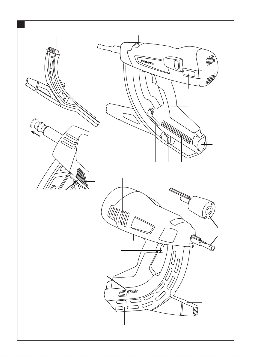
Parts, operating controls and indicators 1
Grip
@
Lockbutton and power regulator
;
Nosepieces
=
Support leg
%
Magazine (20 nails or 40 nails)
&
Type identification plate
(
Gas can compartment
)
Gas can compartment cover
+
Ventilation slots
§
Locking lever
/
Trigger
:
Reset button
·
Nail pusher
$
Belt hook
£
Gas level indicator
|
1.2 Explanation of the pictograms and other
information
Warning signs
General
warning
Obligation signs
Wear eye
protection.
Warning: hot
surface
Wear a hard
hat.
Wear ear
protection.
Wear
protective
gloves.
14
Page 6
Symbols
Read the
operating
instructions
before use.
2 Description
2.1 Use of the product as directed
The tool is designed for driving specially manufactured
nails (fasteners) into concrete, steel and other materials
suitable for the direct fastening technique (please refer to
the Fastening Technology Manual).
The tool is designed for professional use in fastening
applications in the drywall installation trade and other
building trades where fasteners are driven into concrete,
steel, sand-lime block, concrete block and rendered
masonry.
Thetool,gascanandfastenersformasingletechnical
unit. This means that the tool can achieve optimum
fastening performance only when used in conjunction
Location of identification data on the tool
The type designation and serial number can be found on
thetypeidentificationplateonthetool.Makeanoteof
this data in your operating instructions and always refer
to it when making an enquiry to your Hilti representative
or service department.
Type:
Generation: 01
Serial no.:
with the Hilti fasteners and gas cans specially designed
and manufactured for it. The fastening and application
recommendations given by Hilti apply only when these
conditions are observed.
The tool is for hand-held use only.
The tool may be operated, serviced and repaired only by
trained personnel. This personnel must be informed of
any special hazards that may be encountered.
Modification of the tool is not permissible.
Observe the information printed in the operating instructions concerning operation, care and maintenance.
The tool and its ancillary equipment may present hazards
when used incorrectly by untrained personnel or when
used not as directed.
en
3 Accessories, consumables
Designation Description
Gas can GC 21/ GC 22
Nosepiece X‑120 ME TN
Additional nosepieces X‑120 WH (washers)
Magazine X‑120 GM 40/ X‑120 GM 20
Support leg X‑120 SL
Set of pin punches X‑120 NP set
Tool clip X‑120 TS
Nails Length In magazine strips of
X‑EGN 14MX 14 mm (¹/₂") 10 Steel
X‑EGN 18MX 18 mm (¹¹/₁₆") 10 Hard concrete /
X‑EGN 20MX 20 mm (³/₄") 10 Hard concrete /
For use on (please
contact Hilti for detailed information)
precast concrete /
steel
precast concrete /
steel
15
Page 7

Nails Length In magazine strips of
X‑EGN 24MX 24 mm (¹⁵/₁₆") 10 Hard concrete /
X‑GN 20 MX 20 mm (³/₄") 10 Concrete / rendered
en
X‑GN 27 MX 27 mm (1") 10 Concrete / rendered
X‑GN 32 MX 32 mm (1 ¹/₄") 10 Concrete / rendered
X‑GN 39 MX 39 mm (1 ⁹/₁₆") 10 Concrete / rendered
X‑GPN 37 MX 37 mm (1¹/₂") 10 Sheet steel / thin steel
For use on (please
contact Hilti for detailed information)
precast concrete /
steel
masonry (1cm / ³/₈")
/ sand-lime block /
concrete block
masonry (1cm / ³/₈")
/ sand-lime block /
concrete block
masonry (1cm / ³/₈")
/ sand-lime block /
concrete block
masonry (1cm / ³/₈")
/ sand-lime block /
concrete block
Other fasteners
Rings and clips for pipes and conduits X‑FB; X‑DFB
Holder for clips and cables X‑EKB Up to 16 cables
Holder for cable ties X‑ECT
Hanger for threaded rods and wire X‑HS
Universal plastic washer X‑ET
Designation
X‑BX; X‑EMTC
X‑EMTSC
X‑EKS; X‑EKSC
X‑CC
Sizes
8…40 mm
³/₈"‑1"
¹/₂"‑1"
16…40 mm
M4‑M8
W6 thread
4 Technical data
Right of technical changes reserved.
NOTE
The tool is equipped with a transmitter module.
Tool with magazine
Weight 3.8 kg (8.41 lbs)
Dimensions (L x W x H) 431 mm X 134 mm X 392 mm (17" x 5 ¼" x 15 ½")
Nail length Max. 39 mm (max. 1 ⁹/₁₆")
Nail diameter ∅ 3 mm (∅ 0.118 in) / ∅ 2.6 mm (∅ 0.102 in)
Magazine capacity 40 + 2 nails or 20 + 2 nails
Contact movement 40 mm (1 ⁹/₁₆")
Operating temperature / ambient temperature with
GC 21 gas can
Operating temperature / ambient temperature with
GC 22 gas can
-5…+45°C(23°Fto113°F)
-10…+45°C (14°F to 113°F)
16
Page 8

Maximum fastener driving rate 1,200/h
Energy-equivalent acceleration, a
Gas can
Capacity 1 can for 750 nails
Recommended transport and storage temperature +5…+25°C (41°F to 77°F)
Substances contained Isobutane, propene
Gas can Not refillable
The gas can is pressurized. Protect the gas can from
the heat of the sun.
hw, RMS(3)
Recoil: Applicable to 1 mm sheet metal on B45 concrete: 4.04 m/s²
Never expose the gas can to temperatures over 50°C
(122°F).
5 Safety instructions
5.1 Basic information concerning safety
In addition to the information relevant to safety given
in each of thesections ofthese operatinginstructions,
the following points must be strictly observed at all
times.
5.1.1 Personal safety
a) Stay alert, watch what you are doing and use
common sense when operating a direct fastening
tool. Do not use a tool while you are tired or under
the influence of drugs, alcohol or medication.
A moment of inattention while operating tools may
result in serious personal injury.
b) Avoid unfavorable body positions. Make sure you
work from a safe stance and stay in balance at all
times.
c) Never point the tool toward yourself or other per-
sons.
d) Neverpress the nosepiece of thetool against your
hand or against any other part of your body (or
other person’s hand or part of their body).
e) Keep other persons, especially children, away
from the area in which the work is being carried
out.
5.1.2 Fastening tool use and care
a) Use the right tool for the job. Do not use the tool
for purposes for which it was not intended. Use it
only as directed and when in faultless condition.
b) Pressthe tool against theworking surface at right
angles.
c) Never leave a loaded tool unattended.
d) Remove the gas can from the tool before trans-
porting the tool.
e) Always unload the tool (remove the gas can and
fasteners) before cleaning, before carrying out
care and maintenance, before work breaks and
before storing the tool.
f) When not in use, tools must be unloaded and
stored in a dry place, locked up or out of reach of
children.
g) Check the tool or machine and its accessories for
damage and ensure that they function faultlessly
andas intended.Check thatmoving parts function
correctly without sticking and that no parts are
damaged. All parts must be fitted correctly and
fulfill all conditions necessary for correct operation of the tool. Damaged guards, safety devices
and other parts must be repaired or replaced
properly at a Hilti service center unless otherwise
indicated in the operating instructions.
h) Keep the arms slightly bent while operating the
tool (do not straighten the arms).
i) Pull the trigger only when the tool is pressed
against the working surface at right angles.
j) Always hold the tool securely and at right angles
to the working surface when driving a fastener.
This will helpto prevent fasteners being deflected
by the working surface.
k) Never redrive a fastener. This may cause the
fastener to break and the tool may jam.
l) Never drive fasteners into existing holes unless
this is recommended by Hilti.
m) Always observe the application guidelines.
5.1.3 Work area safety
a) Ensure that the workplace is well lit.
b) Operate the tool only in well-ventilated working
areas.
c) Do not attempt to drive fasteners into unsuitable
materials. Materials that are too hard, e.g. welded
steel and cast iron. Materials that are too soft, e.g.
wood and drywall panel (gypsum board). Materials
that are too brittle, e.g. glass and ceramic tiles.
Driving a fastener into these materials may cause
the fastener to break, shatter or to be driven right
through.
d) Before driving fasteners, check that no one is
present immediately behind or below the working
surface.
en
17
Page 9

e) Keep the workplace tidy. Objects which could
cause injury should be removed from the working area. Untidiness at the workplace can lead to
accidents.
f) Keep the grips dry, clean and free from oil and
grease.
g) Wear non-skid shoes.
h) Take the influences of the surrounding area into
en
account. Do not expose the tool to rain or snow
and do not use it in damp or wet conditions. Do
notusethetoolwherethereisariskoffireor
explosion.
5.1.4 Mechanical hazards
a) Select the correct fastener guide and fastener
combination for the job on hand. Failure to use
the correct combination of these items may result in
damage to the tool and/or unsatisfactory fastening
quality.
b) Useonly fasteners of a type approved for usewith
the tool.
c) Never fill the magazine with fasteners unless it is
correctly fitted to the tool. The fasteners could be
ejected uncontrollably.
5.1.5 Thermal hazards
a) If the tool has overheated, allow it to cool down.
Do not exceed the recommended fastener driving
rate.
b) Always wear gloves if the tool has to be dis-
mantled for cleaning or maintenance before it
has been allowed to cool down.
5.1.6 Gasses
Liquid gas under pressure:
Observe the hazard warnings and first-aid instructions printed on the gas can and in the instructions
for use.
The gas is extremely flammable (contains: isobutane,
propene).
Refilling the gas can is not permissible.
a) Do not use damaged gas cans.
b) Do not attempt to force the gas can open. Do not
incinerate or crush the can and do not attempt to
reuse it for any other purpose.
c) Neverspray the gastoward personsor otherliving
beings.
d) Keep the gas away from all sources of ignition
such as naked flames, sparks, pilot lights, static
discharge and very warm surfaces.
e) Do not smoke while using the tool.
5.1.6.1 Storage
a) Do not store gas cans in inhabited rooms or in
rooms connected to inhabited rooms.
b) Store the gas cans in a dry, well-ventilated place.
c) Store the gas cans out of reach of children.
d) Do not expose gas cans to direct sunlight or
temperatures above 50°C (122°F).
e) Recommended storage temperature: 5°C to 25°C
(41°F to 77°F).
5.1.6.2 First aid
Read the material safety data sheet for information
about use, care and maintenance and first-aid measures.
a) Direct skin contact with the liquid gas may cause
frostbite or a serious freezing injury similar to a
burn.
b) In case of inhalation of the gas: The person af-
fected should be taken into the open air and
brought into a comfortable position.
c) In case of unconsciousness: Bring the person af-
fected into a securerecovery position. Should the
person stop breathing, apply artificial respiration
and supply oxygen if necessary.
d) In case of gas contact with the eyes: Rinse the
open eyes under running water for one minute.
e) In case of gas contact with the skin: Wash the
contact surface carefully with warm water and
soap. Subsequently apply a skin cream.
f) Consult a doctor if necessary.
5.1.7 Protective device
Never use the tool if the applicable safety devices
have been damaged or removed.
18
Page 10

6Beforeuse
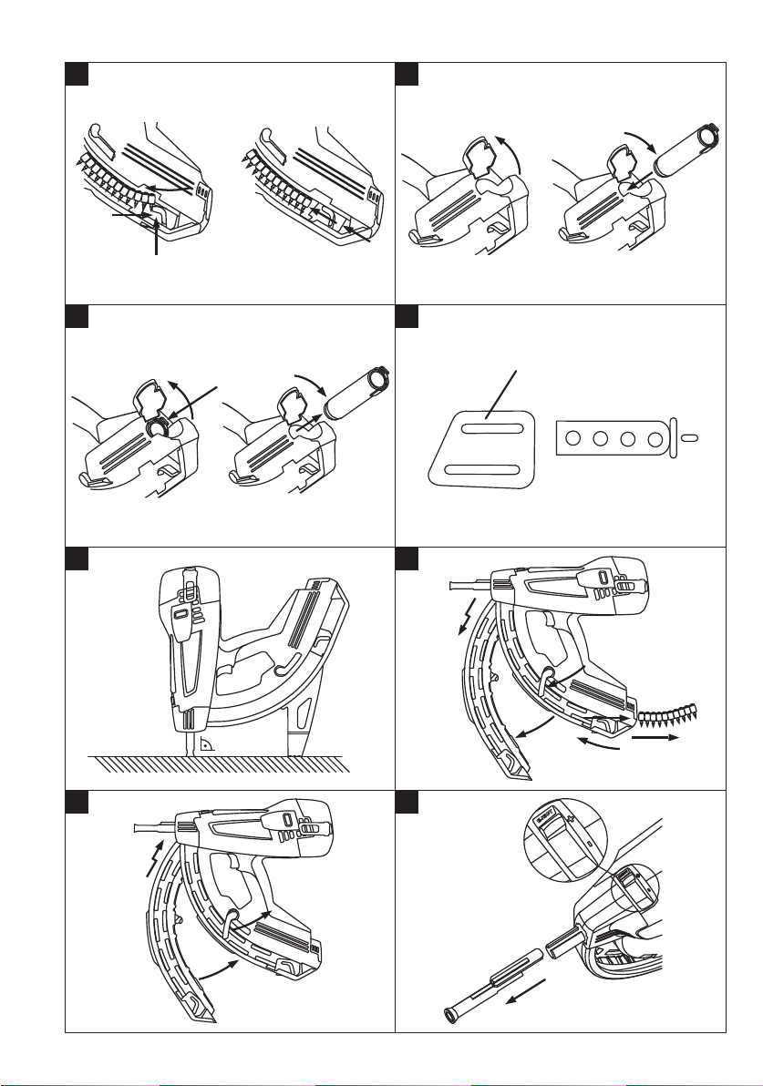
3. Release the nail pusher and allow it to slide forward
slowly.
6.2 Inserting the gas can 3
NOTE
Read the operating instructions before using the tool.
6.1 Inserting nails 2
1. Pull the nail pusher back until it engages.
NOTE The nail pusher must engage in this position.
2. Slide the nails into the magazine (maximum of 4
strips of 10 nails).
6.4 Checking the gas can 5
NOTE
- To check the gas level in the can, press the button marked GAS. When doing so,takecaretoensurethatthetoolis
not pressed against the working surface.
- Even when the indicator shows “empty”, a small quantity of gas, for technical reasons, still remains in the can.
4 LEDs light green constantly. The gas can is full.
2 LEDs light green constantly. The gas can is half full.
1 LED blinks green. The gas can is almost empty. The gas can should be changed.
1 LED lights red constantly. The gas can is empty, no gas can fitted or wrong gas can fitted.
1. Open the cover.
2. Push the gas can into the gas can compartment,
valve first, until the clip engages.
3. Close the cover.
4. Press the tool against the working surface 3 times
without pulling the trigger.
6.3 Removing the gas can 4
1. Open the cover of the gas can compartment.
2. Press the can retaining clip.
3. Remove the gas can.
4. Close the cover of the gas can compartment.
en
7Operation
NOTE
When holding the tool steady with the second hand, the
hand must be positioned in such a way that no ventilation
slots or openings are covered.
CAUTION
Never redrive a fastener. This may cause the fastener
to break and the tool may jam.
WARNING
Material may splinter when the fastener is driven or fragments of the magazine strip may fly off. Splintering material presents a risk of injury to the eyes and body. The
user of the tool and all persons in the vicinity must
wear eye protection and a hard hat.
CAUTION
The fastener is driven by theenergy releasedon ignitionof
a gas-air mixture. Exposure to noise can cause hearing
loss. The operator and bystanders must wear ear
protectors.
WARNING
Never make the tool ready to fire by pressing it against a
part of the body (e.g. the hand). When the tool is ready
to fire, fasteners could be driven inadvertently into parts
of the body. Never press the tool against parts of the
body.
WARNING
Never pull the tool nosepiece back by the fastening
component inserted in it (e.g. soft washer, pipe ring
or clip etc.). This presents an increased risk of accident.
WARNING
The tool must always be unloaded before changing
the magazine and before carrying out cleaning or
maintenance (see section “Unloading the tool”).
19
Page 11

WARNING
Parts of the tool outside the grip area may get hot when
fasteners are driven at a rapid rate over a long period of
time. Wear protective gloves.
NOTE
If the nail is still driven too deeply when the power
regulator is set to “-”, it may be necessary to use a longer
nail.
7.1 Operation 6
NOTE
It is possible to drive a fastener only when more than 3
en
nails are in the magazine.
1. Position the nose of the tool at right angles to
the working surface and then press it against the
working surface as far as it will go.
2. Drive the fastener by pulling the trigger.
3. After driving the fastener, lift the tool away completely from the working surface.
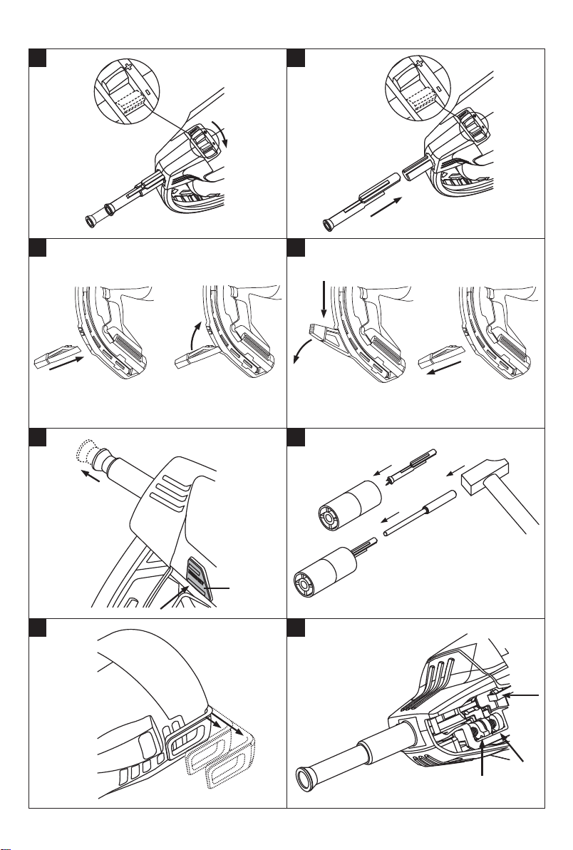
7.1.1 Using pipe rings and other fasteners
If you wish to use pipe rings and other types of fastener,
push the plastic part of the fastener into the tool
nosepiece.
7.2 Gas level indicator 5
Please refer to section 6.4 “Checking the gas can (for 2
seconds)”.
7.3 Fitting and removing the magazine
7.3.1 Removing the magazine 7
1. Pull the nail pusher back until it engages.
NOTE The nail pusher must engage in this position.
2. Remove all fasteners from the magazine.
3. Release the nail pusher and allow it to slide forward
slowly.
4. Push the locking lever down toward the magazine.
5. Pivot the magazine forward away from the tool.
6. Disengage the magazine from the tool.
7.3.2 Fitting the magazine 8
1. Engage the magazine with the tool.
NOTE The locking lever must be in the open position.
2. Guide the magazine toward the tool until the shaped
parts fit together.
3. Close the locking lever and check that it engages.
7.4 Nosepiece
7.4.1 Removing the nosepiece 9
1. Set the power regulator to “Eject”.
2. Remove the nosepiece.
7.4.2 Settings at the nosepiece
NOTE
When the power regulator is set to “+”, the nosepiece is
set to the standard fastener driving depth.
NOTE
When the power regulator is set to “-”, the nosepiece is
set to the reduced fastener driving depth.
7.4.2.1 Setting the standard fastener driving
depth
Set the power regulator to “+”.
7.4.2.2 Setting the reduced fastener driving
depth
NOTE
This setting is suitable for fastening thin sheet metal to
soft materials (e.g. young / green concrete).
Set the power regulator to “-”.
7.4.3 Fitting the tool nosepiece
WARNING
Check to ensure that the tool is not loaded. The tool
could be made ready to fire inadvertently by pressing the
nosepiece in by hand.
1. Align the nosepiece with the slot in the tool.
2. Push the nosepiece onto the tool.
3. While holding the nosepiecewith thehand, press the
tool against the working surface until the nosepiece
engages in position.
7.5 Support leg
7.5.1 Fitting the support leg
1. Push the support leg into the slot in the magazine at
right angles.
2. Turn the support leg through 90° and engage it in
position.
7.5.2 Removing the support leg
1. Release the support leg by pressing the spring
catch.
2. Turn the support leg through 90°.
3. Pull the support leg away from the magazine at right
angles.
7.6 Bringing the piston into the correct position
NOTE
The piston is incorrectly positioned when the tool
nosepiece has not extended to its original position after
the tool is lifted away from the working surface and the
reset button is projecting.
The piston can be returned to the correct position by
pressing the reset button. Fasteners can then be driven.
In exceptional cases, the tool may fire without driving a
fastener when the tool is operated for the first time after
resetting the piston.
Press the reset button.
20
Page 12

7.7 Removing a jammed fastener
1. Remove the magazine.
2. Remove the nosepiece.
3. Fit the nosepiece into the support supplied.
4. Use the pin punch to remove the fastener.
7.9 Application guidelines
NOTE
For detailed information, please ask the Hilti marketing organization in your country for a copy of the Hilti Fastening
Technology Manual or the applicable national regulations.
Concrete
A = min. distance from edge = 70 mm (2¾")
B = min. fastener center spacing = 80 mm (3¹/₈")
C = min. base material thickness = 100 mm (4")
7.8 Unloading the tool
1. Open the cover of the gas can compartment.
2. Press the can retaining clip and remove the gas can.
3. Close the cover of the gas can compartment.
4. Pull the nail pusher back until it engages.
NOTE Thenailpushermustengageinthisposition.
5. Remove the fasteners from the magazine.
6. Release the nail pusher in the magazine and allow it
to slide forward slowly.
B A
ET
C
Steel
A = min. distance from edge = 15 mm (⁵/₈")
B = min. fastener center spacing = 20 mm (¾")
C = min. base material thickness = 4 mm (⁵/32")
en
B A
C
7.10 Belt hook
The belt hook can be used to attach the tool in position
1toabeltorinposition2toaladderorscaffold.
8 Care and maintenance
WARNING
The tool must be unloaded (gas can and fasteners
removed from the tool) before carrying out cleaning
or maintenance.
CAUTION
The tool may get hot during use. You could burn your
hands. Wear protective gloves before carrying out
care and maintenance. Allow the tool to cool down.
21
Page 13

8.1 Care of the tool
CAUTION
Take care not to damage the piston detector, nail
detector and magazine detector.
1. Removeplasticdebrisfromthenosepieceatregular
intervals.
2. Never operate the tool when the ventilation slots are
en
blocked. Clean the ventilation slots carefully using a
dry brush.
3. Do not permit foreign objects to enter the interior of
the tool.
4. Clean the outside of the tool at regular intervals with
a slightly damp cloth.
5. Do not use a spray, steam pressure cleaning equipment or running water for cleaning.
6. Always keep the grip surfaces of the tool free from
oil and grease.
7. Do not use cleaning agents which contain silicone.
8. Do not use Hiltispray orsimilar lubricantsor cleaning
agents.
8.2 Maintenance
Check all external parts of the tool for damage at regular
intervals and check that all controls operate faultlessly.
Do not operate the tool if parts are damaged or when
the controls do not function faultlessly. Have the tool
repaired by Hilti Service.
8.3 Checking the tool after care and maintenance
After cleaning orservicing, check that the powerregulator
is correctly set (standard setting “+”) before inserting the
gas can.
9 Troubleshooting
WARNING
The tool must be unloaded (gas canand fasteners removed fromthe tool) before carrying out cleaning or maintenance.
Fault Possible cause Remedy
Fastener head stand-off is frequently too high.
The power regulator is set to “-”. Set the power regulator to “+”.
The fastener used is too long. Use a shorter fastener.
The base material is too hard. Use a DX fastening tool.
The intake/exhaust valve is dirty or
covered over.
The fastener is frequently driven
too deeply (punches through)
and/or the ring or clip breaks.
Fastener breakage. The power regulator is set to “-”. Set the power regulator to “+”.
22
Driving power is too high. Set the power regulator to “-”.
The fastener is too short. Use a longer fastener.
The fastener used is too long. Use a shorter fastener.
The base material is too hard. Use a DX fastening tool.
The tool is pressed against the surface at an angle.
Clean the tool and pay attention to
the hand position.
Contact Hilti if the problem persists.
Hold the tool at right angles to the
working surface. Use the support leg.
See section: 7.5 Support leg
Page 14

Fault Possible cause Remedy
Fasteners are bent. The power regulator is set to “-”. Set the power regulator to “+”.
The fastener used is too long. Use a shorter fastener.
The tool is pressed against the surface at an angle.
Fastener doesn’t hold in steel. The base material is not thick enough
Gas can doesn’t last for the
whole box of fasteners.
The tool remains compressed
(does not extend when pressure
is released).
Fastener driving failure rate too
high.
The tool doesn’t fire.
(less than 4 mm).
Frequently pressing the tool against
the working surface without pulling
the trigger causes increased gas consumption.
The piston is incorrectly positioned. Press the reset button.
The nail detector is jammed; The reset button still projects after it has
been pressed (white edge still visible).
A fastener is jammed in the tool. Remove the magazine and the tool
The tool is pressed against the surface at an angle.
Wrong type of nail used. Use X-GHP nails if necessary.
The base material is too hard. Use a DX fastening tool.
The nail pusher is in the rearmost po-
sition.
Insufficient number of fasteners in the
magazine (2 or less).
Fastener feed malfunction. Use a different strip of fasteners (strip
Hold the tool at right angles to the
working surface. Use the support leg.
See section: 7.5 Support leg
Use a different fastening technique.
Avoid pressing the tool against the
working surface without pulling the
trigger.
See section: 7.6 Bringing the piston
into the correct position
Remove the gas can and the
magazine from the tool and remove
any dirt or debris from the nail
detector.
nosepiece. Fit the tool nosepiece into
the support supplied and use the pin
punch to remove the fastener.
CAUTION
Do not damage the tool nosepiece.
See section: 7.7 Removing a jammed
fastener
See section: 7.3.1 Removing the
magazine 7
See section: 7.4.1 Removing the
nosepiece 9
See section: 7.8 Unloading the tool
Contact Hilti if the problem persists.
Hold the tool at right angles to the
working surface. Use the support leg.
See section: 7.5 Support leg
Release the nail pusher.
See section: 7.3 Fitting and removing
the magazine
Reload fasteners.
is possibly damaged).
Clean the magazine.
en
23
Page 15
Fault Possible cause Remedy
The tool doesn’t fire. The gas can is empty. Check the gas level by pressing the
No gas can fitted or wrong type of
en
When hot, the tool doesn’t fire
after a pause between use.
The tool doesn’t fire or fires
sporadically.
gas can fitted to the tool.
New gas can fitted, but the tool has
not been pressed against the working
surface 3 times without pulling the
trigger.
Foreign object in the tool nosepiece
section.
The tool is too hot. Allow the tool to cool down.
The fastener driving rate was considerably higher than 1200 per hour and
the gas can is almost empty.
Operation outside the limits of the
permissible ambient conditions.
The gas can is not at the operating
temperature.
Gas bubbles have formed in the gas
injection system.
The tool is not lifted away completely
from the working surface.
button marked GAS.
If only 1 LED lights red constantly, the
gas can is empty. Fit a new gas can.
See section: 7.2 Gas level indicator.
Open the gas can compartment cover
and check the contents.
If a gas can is present in the tool,
press the button marked GAS.
If 1 LED lights red constantly, the
wrong type of gas can has been inserted in the tool. Insert the correct
type of gas can.
See section: 7.2 Gas level indicator.
Press the tool against the working
surface 3 times without pulling the
trigger.
Remove the magazine and nosepiece
and then remove the foreign object
from the tool.
See section: 7.3.1 Removing the
magazine 7
See section: 7.4.1 Removing the
nosepiece 9
Contact Hilti if the problem persists.
Remove the gas can and then refit it.
Then press the tool against the working surface 3 times without firing it.
Check the gas level indicator. If the
LED lights red constantly, the gas can
is empty. Fit a new gas can.
Allow the tool to cool down.
Observe the maximum fastener driving rate (1200 per hour).
Contact Hilti if the problem persists.
If possible, take measures to ensure
that the ambient conditions in the
working environment remain within
the permissible limits.
Use a different fastening technique.
Bring the gas can to the operating
temperature (-5°C to 45°C with
GC 21, -10°C to 45°C with GC 22).
Remove the gas can and then refit it.
Take care to ensure that the tool is lifted away completely from the working
surface after driving each fastener.
24
Page 16
Fault Possible cause Remedy
Fastener cannot be removed
from nosepiece.
Pipe rings and other fasteners
cannot be inserted in the tool
nosepiece.
A fastener is jammed in the tool
nosepiece.
Fragments of the magazine strip are
lodged in the tool nosepiece.
Remove the tool nosepiece from the
tool. Fit the tool nosepiece into the
support supplied and use the pin
punch to remove the fastener.
CAUTION
Do not damage the tool nosepiece.
See section: 7.4.1 Removing the
nosepiece 9
See section: 7.7 Removing a jammed
fastener
Remove the fragments of the
magazine strip from the tool
nosepiece.
10 Disposal
Most of the materials from which Hilti tools or appliances are manufactured can be recycled. The materials must
be correctly separated before they can be recycled. In many countries, Hilti has already made arrangements for
taking back old tools and appliances for recycling. Ask Hilti customer service or your Hilti representative for further
information. If you wish to bring the tool to a materials separation facility yourself: Regional and international directives
and regulations must be observed.
11 Manufacturer’s warranty - tools
Hilti warrants that the tool supplied is free of defects in
materialandworkmanship.Thiswarrantyisvalidsolong
as the tool is operated and handled correctly, cleaned
and serviced properly and in accordance with the Hilti
Operating Instructions, and the technical system is maintained. This means that only original Hilti consumables,
components and spare parts may be used in the tool.
This warranty provides the free-of-charge repair or replacement of defective parts only over the entire lifespan
of the tool. Parts requiring repair or replacement as a
result of normal wear and tear are not covered by this
warranty.
Additional claims are excluded, unless stringent national rules prohibit such exclusion. In particular, Hilti
is not obligated for direct, indirect, incidental or con-
sequential damages, losses or expenses in connection with, or by reason of, the use of, or inability to
use the tool for any purpose. Implied warranties of
merchantability or fitness for a particularpurpose are
specifically excluded.
For repair or replacement, send the tool or related parts
immediately upon discovery of the defect to the address
of the local Hilti marketing organization provided.
This constitutes Hilti’s entire obligation with regard to
warranty and supersedes all prior or contemporaneous
comments and oral or written agreements concerning
warranties.
NOTE
Observe the gas can expiry date printed on the edge of
the can.
en
25
Page 17
12 EC declaration of conformity (original)
Designation: Gas-driven fastening tool
Type: GX 120‑ME
Generation: 01
Year of design: 2007
en
We declare, on our sole responsibility, that this
product complies with the following directives and
standards: 75/324/EEC, 91/155/EEC, 64/548/EEC,
EN ISO 12100, EN 13752‑1:2008‑12, EN 50081‑2,
EN 1127‑1, EN 417, ISO 8662‑11 AMD 1:2001-12,
EN 792‑13:A1:2008‑09, EN 60529:2000‑09,
64/548/EEC, EN 55011:1998+A1:1999, CISPR 11:2003,
A1:2004, IEC 61000‑6‑2:2005, EN 61000‑6‑2:2001,
IS1:2005, IEC 61000‑6‑3:1996, EN 61000‑6‑3:2001,
IEC 61000‑4‑2:1995, IEC 61000‑4‑3:2006,
IEC 61000‑4‑8:1993: A1:2000, 2006/42/EC, 2011/65/EU.
Hilti Corporation, Feldkircherstrasse 100,
FL‑9494 Schaan
Norbert Wohlwend Tassilo Deinzer
Head of Quality & Processes Management
BU DirectFastening BU Direct Fastening
04/2013 04/2013
Head of BU Direct Fastening
Technical documentation filed at:
Hilti Entwicklungsgesellschaft mbH
Zulassung Elektrowerkzeuge
Hiltistrasse 6
86916 Kaufering
Deutschland
13 Health and safety of the operator
13.1 Noise information
Gas-actuated fastening tool
Type GX 120-ME
Model Series
Caliber GC 22
Power regulation
Application Fastening 1 mm sheet metal to concrete (C40) with the
+
X-ECT
Declared measuredvalues of noise characteristicsaccording to 2006/42/ECMachinery Directive in conjunction
with DIN EN 15895
Noise (power) level, L
Emission sound pressure level at the workplace,
2
L
pA, 1s
Peak sound pressure emission level, L
1
±2dB(A)
2
±2dB(A)
3
±2dB(C)
WA, 1S
1
pC, peak
3
106 dB (A)
102 dB (A)
137 dB (C)
Operation and set-up conditions: Set-up and operation of the pin driver in accordance with E DIN EN 15895-1 in the
semi-anechoic test room of Müller-BBM GmbH. The ambient conditions in the test room conform to DIN EN ISO 3745.
Testing procedure: Enveloping surface method in anechoic room on reflective surface area in accordance with
E DIN EN 15895, DIN EN ISO 3745 and DIN EN ISO 11201.
NOTE The noise emissions measured and the associated measurement uncertainty represent the upper limit for the
noise values to be expected during the measurements.
Variations in operating conditions may cause deviations from these emission values.
14. FCC statement
This device complies with Part 15 of the FCC Rules and to RSS-210 of Canada.
Operation is subject to the following two conditions:
(1) this device may not cause harmful interference, and
(2) this device must accept any interference received, including interference that may cause undesired operation.
26
Page 18

Hilti Corporation
LI-9494 Schaan
Tel.:+423 /234 2111
Fax:+423 /234 29 65
www.hilti.com
Hilti = registered trademark of Hilti Corp., Schaan
W 3410 | 1013 | 2-Pos. 1 | 1
Printed in Germany © 2013
Right of technical and programme changes reserved S. E. & O
Printed: 28.11.2013 | Doc-Nr: PUB / 5125187 / 000 / 01
*39199*
.
39199 / A3
39199
 Loading...