

Page 1
GX 100-E
Bedienungsanleitung de
Operating instructions en
Mode d’emploi fr
Istruzioni d’uso it
Manual de instruções pt
Manual de instrucciones es
ΟΟδδηηγγιιεεςς χχρρηησσεεωως
ς
el
Printed: 07.07.2013 | Doc-Nr: PUB / 5069872 / 000 / 00
Page 2

GX
10
0
G
X 100
R
13
11
10
1
12
R
GX
100-
E
GX
1
0
0
E
3
7
4
8
5
6
9
2
9
14
E
1
G
햾
Printed: 07.07.2013 | Doc-Nr: PUB / 5069872 / 000 / 00
Page 3
2
3
1
2
1
2
3
4
G
X 10
0
G
X
1
0
0
R
GX 100-E
GX 100-E
R
5
GX 100-E
GX 100-E
1
2
6
3
5
4
6
GX 100-E
GX 100-E
1
3
2
7
1
2
8
3
1
2
9
1
2
3
Printed: 07.07.2013 | Doc-Nr: PUB / 5069872 / 000 / 00
Page 4
10
G
XGX 100
1
12
1
13
1
2
11
3
1
2
Printed: 07.07.2013 | Doc-Nr: PUB / 5069872 / 000 / 00
Page 5
1
de
Lesen Sie die Bedienungsanleitung vor
Inbetriebnahme unbedingt durch.
Bewahren Sie diese Bedienungsanleitung
immer beim Gerät auf.
Geben Sie das Gerät nur mit Bedienungsanleitung an andere Personen weiter .
GX100-E Gasgerät
Inhalt Seite
1. Allgemeine Hinweise 1
2. Beschreibung 2
3. Zubehör und Verbrauchsmaterial 2
4. Technische Daten 3
5. Sicherheitshinweise 3
6. Inbetriebnahme 5
7. Bedienung 6
8. Pflege und Instandhaltung 8
9. Fehlersuche 8
10. Entsorgung 11
11. Herstellergewährleistung Geräte 11
12. EG-Konformitätserklärung 12
Gerätebauteile
햲 Handgriff
햳 Arretierungstaste
햴 Gerätenase
햵 Schiebehülse
햶 Magazin
햷 Typenschild
햸 Gasdosenfach
햹 Gasdosenfachdeckel
햺 Lüftungsschlitze
햻 V erriegelungshebel
햽 Abzug
햾 Rückstelltaste
햿 Nagelschieber
헀 Gürtelhaken
Die Zahlen verweisen jeweils auf Abbildungen. Die
Abbildungen zum T extfinden Sie auf den ausklappbaren
Umschlagseiten. Halten Sie diese beim Studium der Anleitung geöffnet.
Im Text dieser Bedienungsanleitung bezeichnet «das
Gerät» immer das Gasgerät GX 100-E.
Ort der Identifizierungsdetails auf dem Gerät
Die Typenbezeichnung und die Serienkennzeichnung sind
auf dem Typenschild Ihres Geräts angebracht. Übertragen Sie diese Angaben in Ihre Bedienungsanleitung und
beziehen Sie sich bei Anfragen an unsere Vertretung oder
Servicestelle immer auf diese Angaben.
Typ: GX100-E
Serien Nr.:
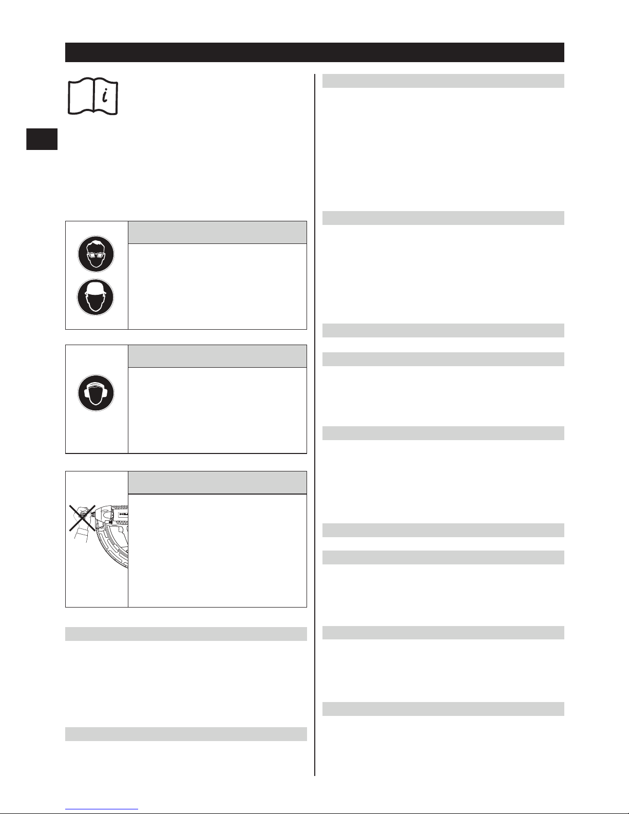
Warnzeichen
Warnung
vor allgemeiner
Gefahr
Warnung
vor explosionsgefährlichen
Stoffen
Warnung
vor heisser
Oberfläche
Gebotszeichen
Schutzhelm
benutzen
Gehörschutz
benutzen
Schutzbrille
benutzen
Vor Benutzung
Bedienungsan-
leitung lesen
Symbole
1. Allgemeine Hinweise
1.1 Signalworte und ihre Bedeutung
-WARNUNG-
Für eine möglicherweise gefährliche Situation, die zu
schweren Körperverletzungen oder zum Todführen könnte.
-VORSICHT-
Für eine möglicherweise gefährliche Situation, die zu
leichten Körperverletzungen oder zu Sachschaden führen
könnte.
-HINWEIS-
Für Anwendungshinweise und andere nützliche Informationen.
1.2 Piktogramme
Printed: 07.07.2013 | Doc-Nr: PUB / 5069872 / 000 / 00
Page 6
2
de
2. Beschreibung
Das Gerät dient zum Setzen von speziell hergestellten
Nägeln in Beton, Stahl und andere für die Direktmontage geeignete Untergründe (siehe Handbuch der Befestigungstechnik). Das Kolbenprinzip gewährleistet eine optimale Arbeits- und Befestigungssicherheit. Als Treibmittel wird Gas eingesetzt.
Das Gerät, die Gasdose, der Ventilkopf und die Befestigungselemente bilden eine technische Einheit. Das bedeutet, dass ein problemloses Befestigen mit diesem Gerät
nur dann gewährleistet werden kann, wenn die speziell
für das Gerät hergestellten Hilti Befestigungselemente
und Gasdosen verwendet werden. Nur bei Beachtung
dieser Bedingungen gelten die von Hilti angegebenen
Befestigungs- und Anwendungsempfehlungen.
2.1 Kolbenprinzip
Die Energie der Gasladung wird auf einen Kolben übertragen, dessen beschleunigte Masse den Nagel in den
Untergrund treibt. Da rund 95% der kinetischen Energie
im Kolben verbleibt, dringt das Befestigungselement mit
einer stark verminderten Geschwindigkeit von weniger
als 100 m/s kontrolliert in den Untergrund ein. Das Abstop-
3. Zubehör, Verbrauchsmaterial
Gasdose mit schwarzem Ventilkopf GC 11 Standard
Gasdose mit grauem Ventilkopf GC 11 HA > 1200 m (3900 ft)
und/oder hohe Setzfrequenz
Gerätenase X-100-E TN
Magazin X-GM 20
Magazin X-GM40
Stütze X-100SL
Hitzepolster X-100HP
Durchschlag X-100NP
Fixbridenhalter X-WH 100-M
Nägel Länge Magaziniert in Streifen zu für Untergrundmaterial
X-GHP 20 MX 20 mm (3/4") 10 Stück Beton
X-GN 27 MX 27 mm (1″) 10 Stück Verputztes Mauerwerk (1 cm)
Kalksandstein / Betonmauerwerk
X-EGN 14 MX 14 mm (1/2″) 10 Stück Stahl
pen des Kolbens im Gerät beendet zugleich den Setzvorgang. So sind bei korrekter Anwendung gefährliche
Durchschüsse praktisch unmöglich.
2.2 Fallsicherung
Durch die Kopplung von Zündmechanismus und Anpressweg ist eine Fallsicherung gegeben. Bei einem Aufprall
des Geräts auf einen harten Untergrund kann deshalb
keine Zündung erfolgen, egal in welchem Winkel das
Gerät auftrifft.
2.3 Abzugsicherung
Die Abzugsicherung gewährleistet, dass bei alleiniger
Betätigung des Abzugs der Setzvorgang nicht ausgelöst
wird. Ein Setzvorgang lässt sich nur auslösen, wenn das
Gerät zusätzlich auf einen festen Untergrund angepresst
ist.
2.3.1 Anpresssicherung
Um den Setzvorgang einzuleiten ist eine deutliche Anpresskraft auf einen festen Untergrund erforderlich.
Printed: 07.07.2013 | Doc-Nr: PUB / 5069872 / 000 / 00
Page 7
4. Technische Daten
Gerät mit Magazin und Gasdose
Gewicht 3,80 kg (8,37 lbs)
Dimension (L×B×H) 425×172×330 mm (163/4″× 63/4″×13″)
Nagellänge max. 39 mm max. (19/16″)
Nageldurchmesser ∅ 3,0 mm (∅ 118 in.)
Magazinkapazität X-GM 20 20 + 2 Nägel
Anpressweg ca. 36 mm (17/16″)
Anpresskraft ca. 120 N (27 lbs)
Anwendungstemperatur / Umgebungstemperatur –5°C bis 45°C (23°F bis 113°F)
Max. Setzfrequenz 600 pro 30 Min.
1000 pro Stunde
Lärminformationen: Ergebnisse für 1 mm Blech auf Beton B45
1b) Schallleistungspegel L
WA, 1S
109 dB (A)
arbeitsplatzbezogener Emmisionswert L
pAImax
102 dB (A)
(gemessen am Ort der Ohren der Bedienungsperson)
1e) Messflächenschalldruckpegel L ’
–
pA, 1s
96 dB (A)
(Abweichende Arbeitsbedingungen können zu anderen Emissionswerten führen)
Gasdose
Kapazität 1 Dose für 750 Nägel
Empfohlene Transport- und Lagertemperatur +5°C bis +25°C (41°F bis 77°F)
Die Gasdose steht unter Druck.
Schützen Sie die Gasdose vor Sonnenbestrahlung.
Die Gasdose darf nie T emperaturen über 50°C (122°F) ausgesetzt werden.
Enthält Dimethyläther, Isobutan, Propylen, Propan,
Butan, Ethanol und Isoparafin
Gasdose Nicht nachfüllbar
TechnischeÄnderungen vorbehalten
3
de
5. Sicherheitshinweise
5.1 Grundlegende Sicherheitsvermerke
Neben den sicherheitstechnischen Hinweisen in den einzelnen Kapiteln dieser Bedienungsanleitung sind folgende
Bestimmungen jederzeit strikt zu beachten.
5.2 Bestimmungsgemässe Verwendung
Das Gerät dient vornehmlich dem professionellen Benutzer. Angewendet wird es in der Elektro- und SHK-Branche sowie für geeignete Anwendungen im Bauhaupt- und
Baunebengewerbe zum Setzen von Nägeln in Beton, Stahl,
Kalksandstein, Betonmauerwerk und verputztes Mauerwerk.
G Manipulationen oder Veränderungen am Gerät sind
nicht erlaubt.
G Benutzen Sie, um Verletzungsgefahren zu vermeiden,
nur original Hilti Zubehör und Verbrauchsmaterial.
G Beachten Sie die Angaben zu Betrieb, Pflege und Instand-
haltung in der Bedienungsanleitung.
G Richten Sie das Gerät nicht gegen sich oder eine ande-
re Person.
G Pressen Sie das Gerät nicht gegen Ihre Hand oder einen
anderen Körperteil (bzw. einer anderen Person).
G Setzen Sie keine Nägel in Untergrundmaterial, das
ungeeignet ist wie:
- Material das zu hart ist wie z.B. geschweisster Stahl
und Gussstahl.
- Material das zu weich ist wie z.B. Holz und Gipskarton.
- Material das zu spröde ist wie z.B. Glas und Fliessen.
Das Setzen in diese Materialien kann einen Nagelbruch
oder ein Durchsetzen verursachen.
Printed: 07.07.2013 | Doc-Nr: PUB / 5069872 / 000 / 00
Page 8

4
de
G Vom Gerät und seinen Hilfsmitteln können Gefahren
ausgehen, wenn sie von unausgebildetem Personal
unsachgemäss behandelt oder nicht bestimmungsgemäss verwendet werden.
G Betätigen Sie den Abzug nur, wenn das Gerät Kontakt
mit dem Untergrundmaterial hat.
G Halten Sie das Gerät immer fest und rechtwinklig zum
Untergrundmaterial. Dadurch wird ein Ablenken des
Nagels vom Untergrundmaterial verhindert.
G Setzen Sie nie einen Nagel durch eine zweite Setzung
nach, es kann zu Nagelbrüchen führen.
G Setzen Sie nie in ein bestehendes Loch, ausser wenn
es von Hilti empfohlen wird.
G Beachten Sie immer die Anwendungsrichtlinien.
5.3 Sachgemässe Einrichtung der Arbeitsplätze
G Tragen Sie rutschfestes Schuhwerk und sorgen Sie
jederzeit für sicheren Stand.
G Vermeiden Sie eine ungünstige Körperhaltung.
G Setzen Sie das Gerät nicht Niederschlägen aus, benut-
zen Sie es nicht in feuchter oder nasser Umgebung
sowie in der Nähe von brennbaren Flüssigkeiten oder
Gasen.
G Sorgen Sie für eine gute Beleuchtung.
G Setzen Sie das Gerät nur in gut belüfteten Arbeitsbe-
reichen ein.
G Halten Sie das Arbeitsumfeld frei von Gegenständen
an denen Sie sich verletzen könnten.
G Das Gerät darf nur handgeführt eingesetzt werden.
G Halten Sie bei der Betätigung des Geräts die Arme
gebeugt (nicht gestreckt).
G Halten Sie beim Arbeiten andere Personen, insbeson-
dere Kinder, vom Wirkungsbereich fern.
G Vergewissern Sie sich, bevor Sie Nägel setzen, dass
sich niemand hinter oder unter dem Arbeitsplatz aufhält.
G Halten Sie den Handgriff trocken, sauber und frei von
Öl und Fett.
5.4 Allgemeine Sicherheitsmassnahmen
G Das Gerät darf nur in einwandfreiem Zustand bestim-
mungsgemäss betrieben werden.
G Lassen Sie ein geladenes Gerät nie unbeaufsichtigt.
G Entladen Sie das Gerät immer vor Reinigungs-, Servi-
ce- und Unterhaltsarbeiten und vor Arbeitsunterbrüchen
(Gasdose und Nägel entfernen).
G Nicht in Gebrauch stehende Geräte müssen entladen
und getrennt von der Gasdose an einem trockenen,
hochgelegenen oder abgeschlossenen Ort ausserhalb
der Reichweite von Kindern, aufbewahrt werden.
G Nehmen Sie für den Transport die Gasdose aus dem
Gerät.
G Verwenden Sie das Gerät nicht, wenn Teile beschädigt
oder gebrochen sind.
5.4.1 Mechanisch
G Verwenden Sie nur Nägel, die für das Gerät zugelas-
sen sind.
G Füllen Sie keine Nägel in das Magazin, wenn es nicht
korrekt an das Gerät montiert ist. Die Nägel können
herausgeschleudert werden.
5.4.2 Thermisch
G Lassen Sie das Gerät abkühlen, wenn es heiss ist.
G Überschreiten Sie nicht die maximale Setzfrequenz
(Anzahl Setzungen pro Zeiteinheit). Das Gerät könnte
sonst überhitzt werden.
5.4.3 Gase
-WARNUNG-
Flüssiggas unter Druck.
Beachten Sie die Gefahren- und Erste-Hilfehinweise auf
der Gasdose.
Das Gas ist äusserst leicht entflammbar (Enthält: Dimethyläther, Isobutan, Propylen, Propan, Butan, Ethanol
und Isoparafin).
Die Gasdose kann nicht nachgefüllt werden.
G Setzen Sie keine beschädigten Gasdosen ein.
G Versuchen Sie nicht, eine Gasdose zu öffnen.
G Sprühen Sie nie Gas gegen Personen und andere Lebe-
wesen.
G Halten Sie das Gas von allen Zündquellen wie offenem
Feuer ,Funken, Zündflammen, statischen Entladungen
und sehr warmen Oberflächen fern.
G Rauchen Sie nicht während der Anwendung.
G Versuchen Sie nicht die Gasdose gewaltsam zu öff-
nen, zu verbrennen, zusammen zu drücken oder für
irgendeinen andern Zweck wieder zu verwenden.
Lagerung
G Lagern Sie keine Gasdosen in einem bewohnten Raum
oder in einen Raum, der zu einem bewohnten Raum führt.
G Bewahren Sie die Gasdosen nur in gut belüfteten und
trockenen Bereichen auf.
G Bewahren Sie die Gasdose ausserhalb der Reichwei-
te von Kindern auf.
G Setzen Sie die Gasdosen nicht dem direkten Sonnen-
licht oder Temperaturen über 50°C (122°F) aus.
G Empfohlene Lagertemperatur 5°C bis 25°C (41°F bis
77°F).
Erste Hilfe
-WARNUNG-
G Direkter Kontakt mit dem Flüssiggas kann Frostbeu-
len oder schwere Verbrennungen zur Folge haben.
Printed: 07.07.2013 | Doc-Nr: PUB / 5069872 / 000 / 00
Page 9
5
de
G Hat eine Person Gas eingeatmet, führen Sie sie ins
Freie und bringen Sie sie in eine bequeme Lage.
G Ist eine Person bewusstlos, bringen Sie sie in eine sta-
bile Seitenlage. Atmet die Person nicht, beatmen Sie
sie künstlich und wenden Sie wenn nötig Sauerstoff
an.
G Bei Augenkontakt mit Gas spülen Sie die offenen Augen
während mehrerer Minuten mit fliessendem Wasser .
G Bei Hautkontakt mit Gas waschen Sie die Kontaktfläche
sorgfältig mit Seife und warmem Wasser . Wenden Sie
nachträglich eine Hautcreme an.
G Wenn nötig ziehen Sie einen Arzt zu.
5.5 Anforderung an den Benutzer
G Das Gerät ist für den professionellen Benutzer bestimmt.
G Das Gerät darf nur von autorisiertem, eingewiesenem
Personal bedient, gewartet und instand gehalten werden. Dieses Personal muss speziell über die auftretenden Gefahren unterrichtet sein.
G Arbeiten Sie stets konzentriert. Gehen Sie überlegt vor
und verwenden Sie das Gerät nicht, wenn Sie unkonzentriert sind.
5.6 Persönliche Schutzausrüstung
G Der Benutzer und die sich in der Nähe aufhaltenden
Personen müssen während der Benutzung und Fehlerbehebung des Geräts eine geeignete Schutzbrille,
einen Schutzhelm und einen Gehörschutz benutzen.
5.7 Schutzeinrichtung
G Setzen Sie das Gerät nie ein wenn die Schiebehülse
(Schutzeinrichtung) beschädigt ist oder entfernt wurde.
6. Inbetriebnahme
-WARNUNG-
Im Magazin dürfen keine Nägel sein.
Die Gasdose muss aus dem Gasdosenfach entfernt sein.
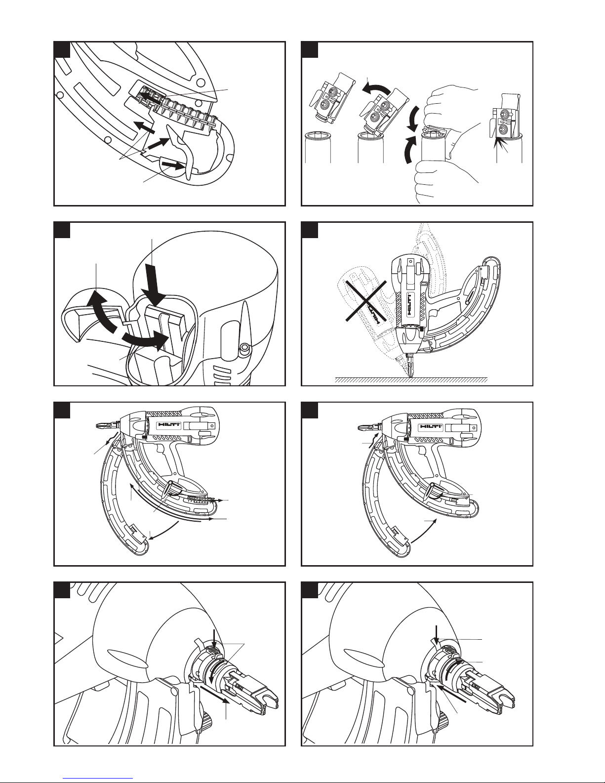
6.1 Nägel einlegen
1. Ziehen Sie den Nagelschieber zurück, bis er einrastet.
-HINWEIS-
Der Nagelschieber muss einrasten.
2. Schieben Sie die Nägel in das Magazin (maximal 2
Streifen à 10 Nägel).
3. Entriegeln Sie den Nagelschieber und lassen Sie ihn
langsam nach vorne gleiten.
6.2 Gasdose vorbereiten
1. Setzen Sie den Ventilkopf an den Innenrand der Gasdose.
2. Pressen Sie den Ventilkopf auf die Gasdose bis er
einrastet.
-HINWEIS-
Kontrollieren Sie den richtigen Sitz des Ventilkopfs auf
dem Ventilsitz. Leichtes Spiel ist normal.
-VORSICHT-
Ein einmal auf die Gasdose aufgesetzter Ventilkopf darf
nicht mehr abgenommen werden, ausser er wird der Entsorgung zugeführt.
6.3 Gasdose einlegen
1. Schwenken Sie den Deckel des Gasdosenfachs am
Gerät auf.
2. Schieben Sie die Gasdose mit dem Boden voran in das
Gasdosenfach bis sie einrastet.
-HINWEIS-
Der Pfeil auf dem Ventilkopf muss nach aussen und
die weisse Platte gegen das Gerät zeigen.
3. Schwenken Sie den Deckel des Gasdosenfachs zu, bis
er einrastet.
Printed: 07.07.2013 | Doc-Nr: PUB / 5069872 / 000 / 00
Page 10
6
de
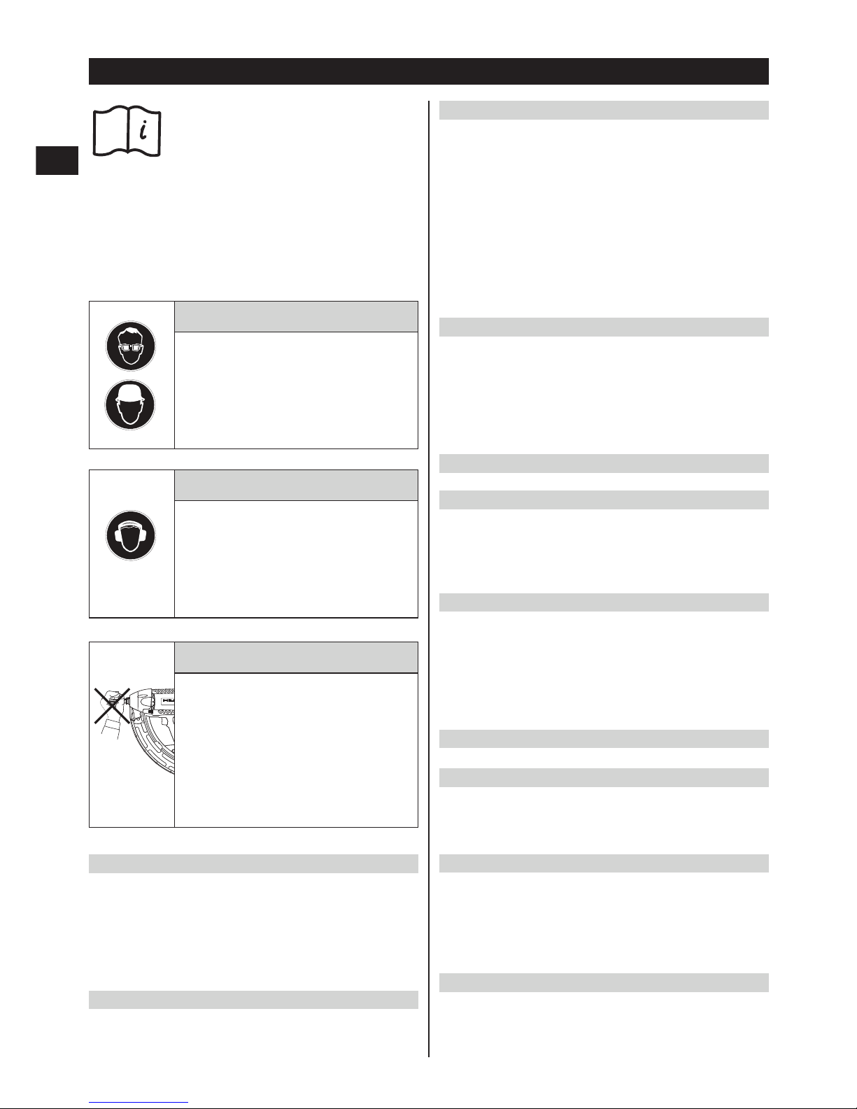
-WARNUNG-
G Durch das Setzen der Nägel kann
Material absplittern.
G Abgesplittertes Material kann Körper
und Augen verletzen.
G Benutzen Sie eine Schutzbrille und
einen Schutzhelm.
GX100
GX 100
R
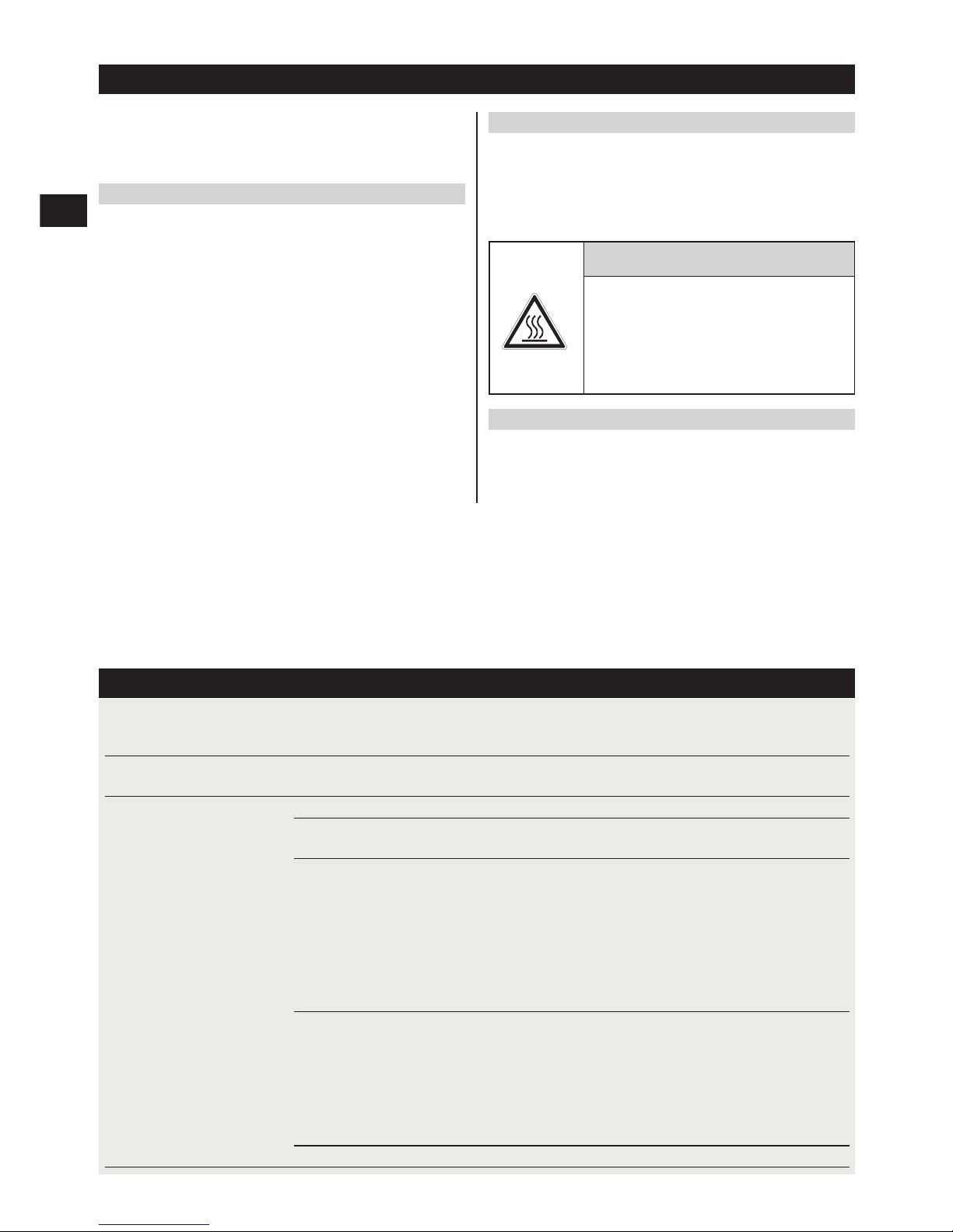
-WARNUNG-
G Durch Anpressen auf einen Körper-
teil (z.B. Hand) wird das Gerät, nicht
bestimmungsgemäss, einsatzbereit
gemacht.
G Die Einsatzbereitschaft ermöglicht
eine Setzung auch in Körperteile.
G Pressen Sie das Gerät nie gegen Kör-
perteile.
-VORSICHT-
G Das Setzen der Nägel wird durch die
Zündung eines Gas- Luftgemischs
ausgelöst.
G Zu starker Schall kann das Gehör
schädigen.
G Benutzen Sie einen Gehörschutz.
7. Bedienung
-HINWEIS-
Beim Festhalten mit der zweiten Hand müssen Sie die
Hand so plazieren, dass Sie keine Lüftungsschlitze oder
Öffnungen verdecken.
-VORSICHT-
Nie einen Nagel durch eine zweite Setzung nachsetzen.
7.1 Betrieb
-HINWEIS-
Eine Setzung ist nur möglich, wenn im Magazin mehr als
2 Nägel sind.
1. Setzen Sie das Gerät rechtwinklig auf die Arbeitsfläche
und pressen Sie es bis zum Anschlag an.
2. Lösen Sie durch Drücken des Abzugs die Setzung aus.
7.2 Magazin demontieren
-HINWEIS-
Vor jedem Magazinwechsel muss das Gerät entladen
werden (siehe 7.6).
7.2.1 Magazin abnehmen
1. Ziehen Sie den Nagelschieber zurück, bis er einrastet.
-HINWEIS-
Der Nagelschieber muss richtig einrasten.
2. Entnehmen Sie alle Nägel aus dem Magazin.
3. Entriegeln Sie den Nagelschieber und lassen Sie ihn
langsam nach vorne gleiten.
4. Schieben Sie den Verriegelungshebel nach unten in
Richtung des Magazins.
5. Schwenken Sie das Magazin nach vorne vom Gerät
weg.
6. Hängen Sie das Magazin vom Gerät ab.
7.2.2 Magazin einsetzen
1. Hängen Sie das Magazin am Gerät ein.
-HINWEIS-
Der Verriegelungshebel muss geöffnet sein.
2. Führen Sie das Magazin gegen das Gerät, bis es mit
den Konturen des Geräts übereinstimmt.
3. Schliessen Sie den Verriegelungshebel, bis er einrastet.
7.3 Gerätenase
7.3.1 Gerätenase demontieren
1. Drücken Sie die Arretierungstaste und drehen Sie die
Gerätenase gegen die Pfeilrichtung.
2. Halten Sie die Arretierungstaste gedrückt und ziehen
Sie die Gerätenase nach vorne vom Gerät.
7.3.2 Gerätenase montieren
1. Richten Sie die Arretierungstaste der Gerätenase auf
die Kerbe am Gerät aus.
2. Schieben Sie die Gerätenase bis zur End-Position auf
das Gerät.
3. Drehen Sie die Gerätenase in Pfeilrichtung bis sie einrastet.
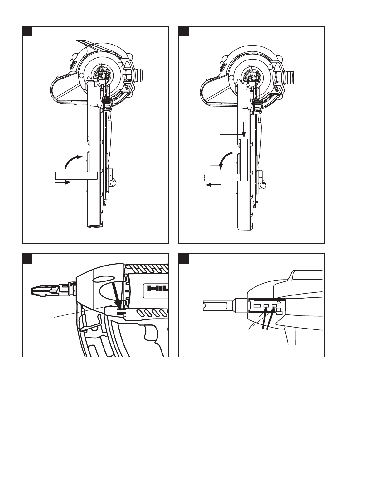
7.4 Stütze
7.4.1 Stütze montieren
1. Schieben Sie die Stütze in einem 90° Winkel in den
Schlitz am Magazin.
2. Drehen Sie die Stütze um 90° und rasten Sie sie ein.
7.4.2 Stütze demontieren
1. Lösen Sie durch Drücken des Federelements die Stütze.
2. Drehen Sie die Stütze um 90°.
3. Ziehen Sie die Stütze in einem 90° Winkel vom Magazin.
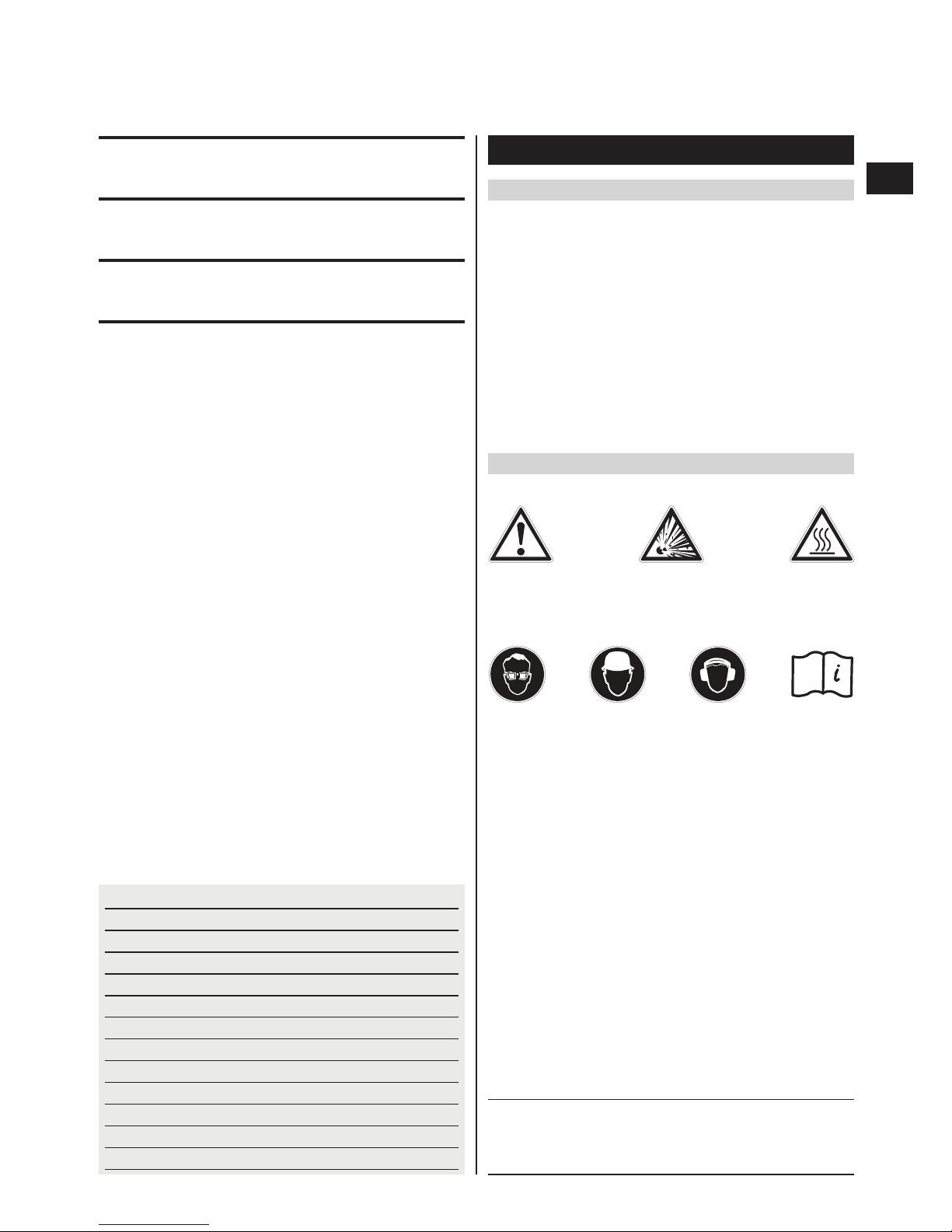
7.5 Kolbenfehlstand beheben
-HINWEIS-
Ein Kolbenfehlstand ist daran erkennbar, dass sich die
Gerätenase nach dem Abheben nicht nach vorne in ihre
Ausgangsstellung bewegt hat.
Printed: 07.07.2013 | Doc-Nr: PUB / 5069872 / 000 / 00
Page 11
7
de
Durch Drücken der Rückstelltaste wird ein Kolbenfehlstand behoben. Anschliessend können wieder Setzungen ausgeführt werden. In Ausnahmefällen kann die erste
Setzung nach dem Drücken der Rückstelltaste eine Leersetzung (ohne Nagel) sein.
1. Drücken Sie die Rückstelltaste (der Schaltweg führt
leicht nach unten).
7.6 Gerät entladen
1. Schwenken Sie den Deckel des Gasdosenfachs auf.
2. Entriegeln Sie die Gasdose durch drücken in Pfeilrichtung am Ventilkopf.
3. Nehmen Sie die Gasdose aus dem Gasdosenfach.
-VORSICHT-
Ein einmal auf den Ventilsitz (Gasdose) aufgesetzter
Ventilkopf darf nicht mehr abgenommen werden, ausser er wird der Entsorgung zugeführt. Legen Sie die
Gasdose mit dem Ventilkopf in den Gerätekoffer.
4. Schwenken Sie den Deckel des Gasdosenfachs zu.
5. Ziehen Sie den Nagelschieber zurück bis er einrastet.
-HINWEIS-
Der Nagelschieber muss richtig einrasten.
6. Entfernen Sie die Nägel aus dem Magazin.
7. Entriegeln Sie den Nagelschieber am Magazin und lassen Sie ihn langsam nach vorne gleiten.
7.7 Anwendungsrichtlinien
Für detaillierte Informationen fordern Sie bitte von Ihrer
Hilti-Marktorganisation das Handbuch der Befestigungstechnik oder gegebenenfalls nationale Vorschriften an.
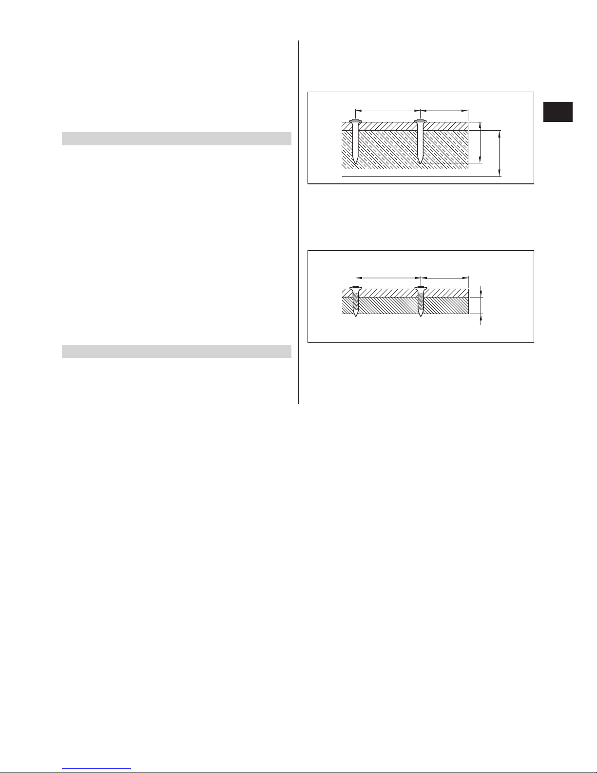
Beton
A = min. Kantenabstand = 70 mm (2
3
/4″)
B = min. Achsabstand = 80 mm (3
1
/8″)
C = min. Untergrunddicke = 100 mm (4″)
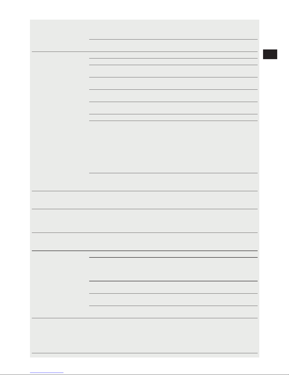
Stahl
A = min. Kantenabstand = 15 mm (
5
/8″)
B = min. Achsabstand = 20 mm (
3
/4″)
C = min. Untergrunddicke = 4 mm (
5
/32″)
BA
ET
C
BA
C
Printed: 07.07.2013 | Doc-Nr: PUB / 5069872 / 000 / 00
Page 12

8
de
8. Pflege und Instandhaltung
-WARNUNG-
Vor Pflege und Instandhaltungsarbeiten muss das Gerät
entladen werden (Gasdose und Nägel aus dem Gerät entfernen).
8.1 Pflege des Geräts
G Entfernen Sie regelmässig die Kunststoffreste von der
Gerätenase.
G Betreiben Sie das Gerät nie mit verstopften Lüftungs-
schlitzen! Reinigen Sie die Lüftungsschlitze vorsichtig mit einer trockenen Bürste.
G Verhindern Sie das Eindringen von Fremdkörpern in
das Innere des Geräts.
G Reinigen Sie die Geräteaussenseite regelmässig mit
einem leicht angefeuchteten Putzlappen.
G Verwenden Sie kein Sprühgerät, Dampfstrahlgerät oder
fliessendes Wasser zur Reinigung!
G Halten Sie die Griffpartien am Gerät immer frei von Öl
und Fett.
G Verwenden Sie keine silikonhaltigen Pflegemittel.
G Verwenden Sie keinen Hilti-Spray oder ähnliche Schmier-
und/oder Pflegemittel.
-VORSICHT-
G Beschädigen Sie den Nageldetektor nicht
8.2 Instandhaltung
Prüfen Sie regelmässig alle aussenliegenden Teile des
Geräts auf Beschädigungen und alle Bedienungselemente
auf einwandfreie Funktion. Betreiben Sie das Gerät nicht,
wenn Teile beschädigt sind oder Bedienelemente nicht
einwandfrei funktionieren. Lassen Sie das Gerät vom
Hilti-Service reparieren.
9. Fehlersuche
-WARNUNG-
Vor Fehlerbehebungsarbeiten muss das Gerät entladen werden (Gasdose und Nägel aus dem Gerät entfernen).
Fehler Mögliche Ursache Behebung
Geringe Energie Gasdose ist fast leer Neue Gasdose einsetzen
(zu grosse Nagelvorstände) Ventilkopf ist defekt Neuen Ventilkopf auf neue Gasdose
aufsetzen
Fremdkörper im Bereich Magazin/ Magazin entfernen. Fremdkörper entGerätenase verklemmt. fernen.
Gerät kollabiert (Vorwärtsbewegung Falls nicht erfolgreich:
der Gerätenase nach dem Abheben Gerät einsenden an Hilti Reparatur Center
vom Untergrund in die Ausgangsstellung)
nicht vollständig oder zu langsam.
(Grobprüfung:
Axial-Spiel Gerätenase prüfen
[Soll: 1–2mm])
Zu tiefe Betriebstemperatur Auf Zimmertemperatur (~20°C / ~68°F)
vorgewärmte Dose verwenden.
(In der Hosentasche oder im warmen
Raum vorgewärmte Dose verwenden)
-WARNUNG-
Wärmen Sie die Gasdose nicht mit heissen
Gegenständen oder einer Flamme auf.
Kolbenfehlstand Siehe Kolbenfehlstand
-VORSICHT-
G Das Gerät kann durch den Einsatz
heiss werden.
G Sie können sich Körperteile verbren-
nen.
G Lassen Sie das Gerät abkühlen.
8.3 Kontrolle nach Pflege- und Instandhaltungsarbeiten
Nach Pflege- und Instandhaltungsarbeiten und vor dem
Einlegen der Gasdose ist zu prüfen, ob die Schiebehülse (Schutzeinrichtung) angebracht ist und fehlerfrei funktioniert (ohne Kraftaufwand verschiebbar ist).
Printed: 07.07.2013 | Doc-Nr: PUB / 5069872 / 000 / 00
Page 13
9
de
Kolbenfehlstand Gerät ist zu heiss Per Druckknopf entriegeln (Rückstelltaste
), weiter setzen (evtl. eine Leersetzung)
Evtl. Gerät abkühlen lassen
Gasdose ist fast leer Neue Gasdose, mit neu aufgestecktem
Ventilkopf, einsetzen
Keine Zündung Gasdose ist fast leer Neue Gasdose einsetzen
Ventilkopf ist defekt Neuer Ventilkopf auf neue Gasdose aufsetzen
Ventilkopf falsch / nicht Ventilkopf korrekt auf die Gasdose
vollständig aufgesetzt aufsetzen
Gasdose ist nicht richtig im Gerät Gasdose richtig im Gerät einsetzen
eingesetzt
Zu tiefe Betriebstemperatur Auf Zimmertemperatur (~20°C / ~68°F)
vorgewärmte Gasdose verwenden.
Ferromagnetische Fremdkörper Fremdkörper vom Magazin entfernen
haften am Magazin
Magazin ist defekt Mit anderem Magazin probieren
Ventilkopf dosiert nicht richtig Gasdose entnehmen und abkühlen lassen
oder wiederholt Ventilkopf betätigen
(weisse Platte am Ventilkopf gegen den
Ventilkopf drücken, bis der Ventilkopf
wieder funktioniert.
-WARNUNG-
Düsenöffnung nie gegen Lebewesen,
offene Flammen oder heisse Gegenstände
richten.
Elektronik ist defekt Falls Elektronik defekt, ist keine unmittel-
bare Fehlerbehebung möglich. Reparatur in
Hilti Reparatur Center
-VORSICHT-
Vor den nachfolgend mit * bezeichneten Manipulationen 10 Sekunden warten und anschliessend wenn möglich
die Gasdose mit dem Ventilkopf aus dem Gasdosenfach entfernen.
Nagel in Bolzenführung Mehrere Nägel sind aufeinander gesetzt * Magazin und Gerätenase abnehmen,
verklemmt Nägel nach vorne herausziehen
* Gerätenase abnehmen, Nägel nach hinten
zurückschlagen
Nagel in „Führung“ Nagel hat sich beim Setzvorgang * Magazin abnehmen, Nagel entfernen
(Magazin-Stahlteil) verklemmt
verklemmt
Gerät kollabiert nicht Kolbenfehlstand * Siehe Kolbenfehlstand
(Vorwärtsbewegung der Nagel ist unter Taster verklemmt * Magazin abnehmen, Nagel entfernen.
Gerätenase nach dem -VORSICHT-
Abheben vom Untergrund) Taster und Nageldetektor nicht beschädi-
gen
Nageldetektion verklemmt Bügel * Gerätenase von Hand oder mit Zange
(evtl. aufgrund von Verschmutzung) herausziehen
Abzug ist in der hinteren Stellung * Abzug mit Zange oder von Hand in
verklemmt Ausgangsstellung bringen
Lose Nägel / Fremdkörper in * Magazin abnehmen, Fremdkörper entAbdeckhaube fernen. Reparatur in Hilti Reparatur Center
Gasdose kann nicht Gerät kollabiert nicht * Magazin abnehmen, Nagel entfernen.
entnommen werden Deckel des Gasdosenfachs öffnen und
Ventilkopf in Pfeilrichtung nach aussen
drücken, bis der Ventilkopf von Gasdose
abspringt.
Ventilkopf und Dose einzeln entnehmen
Printed: 07.07.2013 | Doc-Nr: PUB / 5069872 / 000 / 00
Page 14

10
de
Magazin: Verschmutzung Von aussen reinigen
Nagelschieber klemmt Mit Druckluft reinigen
Fremdkörper Fremdkörper von aussen entfernen
Magazin nicht montierbar Gummi-Puffer auf Rasthaken des Gummi-Puffer ersetzen
Magazins fehlt
Verriegelungshebel nicht ganz nach Verriegelungshebel ganz nach unten (90°)
unten (90°) gedreht drehen
Anpressen nicht möglich Magazin leer, bzw. nur 1 oder 2 Nägel Magazin laden
im Magazin
Auf Fremdkörper angepresst Auf saubere Unterlage anpressen
Kunststoffrest in Gerätenase Kunststoffrest entfernen
verklemmt
Nagelschieber in hinterer Rastposition Nagelschieber lösen
Nagelschieber klemmt Nagelschieber lösen Magazin reinigen /
Fremdpartikel entfernen
Hülse verdreht, nicht in eingerasteter Hülse in richtige Stellung bringen
Stellung
Gasdose nicht richtig in das Gerät Gasdose richtig einlegen
eingelegt
Nagel in Bolzenführung vorgerutscht Magazin abnehmen, Nagel entfernen
Lose Nägel / Fremdkörper in Magazin abnehmen, Fremdkörper
Abdeckhaube entfernen, Reparatur in Hilti Reparatur
Center
Gerätenase rastet nicht ein Arretierungstase gebrochen/ Gerätenase ersetzen.
deformiert Reparatur in Hilti Reparatur Center
Leckage Gasdose bzw. Fehlerhafte Schnittstelle Gasdose entnehmen, Ventilkopf entfernen,
Schnittsstelle Gasdose / Gasdose / Ventilkopf entsorgen.
Ventilkopf (Neue Gasdose mit neu aufgestecktem
Ventilkopf einsetzen)
Falls keine Behebungsmassnahme erfolgreich ist, bringen Sie das Gerät zum Hilti Reparatur Center.
Printed: 07.07.2013 | Doc-Nr: PUB / 5069872 / 000 / 00
Page 15

11
de
10. Entsorgung
Hilti-Geräte sind zu einem hohen Anteil aus wiederverwendbaren Materialien hergestellt. Voraussetzung für eine
Wiederverwendung ist eine sachgemässe Stofftrennung. In vielen Ländern ist Hilti bereits eingerichtet, Ihr Altgerät zur Verwertung zurückzunehmen. Fragen Sie den Hilti Kundenservice oder Ihren Verkaufsberater . Befolgen
Sie die regionalen und internationalen Richtlinien und Vorschriften.
Trennen Sie die Einzelteile wie folgt:
Bauteil / Baugruppe Hauptwerkstoff Verwertung
Transportkoffer Kunststoff Kunststoffrecycling
Aussengehäuse Kunststoff / Elastomer Kunststoffrecycling
Batterie Batterie-Recycling
(-HINWEIS- (länderspezifische Bestimmungen
Die Batterie ist für die Lebensdauer des Geräts ausgelegt) beachten)
Elektronikteile Verschiedene Elektronikschrott
Schrauben, Kleinteile Stahl Altmetall
Ventilkopf Kunststoff Kunststoffrecycling
Gasdose Beachten Sie regionale und nationale
Vorschriften.
11. Herstellergewährleistung Geräte
Hilti gewährleistet, dass das gelieferte Gerät frei von
Material- und Fertigungsfehler ist. Diese Gewährleistung gilt unter der Voraussetzung, dass das Gerät in
Übereinstimmung mit der Hilti Bedienungsanleitung
richtig eingesetzt und gehandhabt, gepflegt und gereinigt wird, und dass die technische Einheit gewahrt
wird, d.h. dass nur Original Hilti Verbrauchsmaterial,
Zubehör und Ersatzteile mit dem Gerät verwendet werden.
Diese Gewährleistung umfasst die kostenlose Reparatur oder den kostenlosen Ersatz der defekten Teile
während der gesamten Lebensdauer des Gerätes. Teile, die dem normalen Verschleiss unterliegen, fallen
nicht unter diese Gewährleistung.
Weitergehende Ansprüche sind ausgeschlossen,
soweit nicht zwingende nationale Vorschriften entgegenstehen. Insbesondere haftet Hilti nicht für
unmittelbare oder mittelbare Mangel- oder Mangelfolgeschäden, Verluste oder Kosten im Zusammenhang
mit der Verwendung oder wegen der Unmöglichkeit
der Verwendung des Gerätes für irgendeinen Zweck.
Stillschweigende Zusicherungen für Verwendung
oder Eignung für einen bestimmten Zweck werden
ausdrücklich ausgeschlossen.
Für Reparatur oder Ersatz sind Gerät oder betroffene
Teile unverzüglich nach Feststellung des Mangels an
die zuständige Hilti Marktorganisation zu senden.
Die vorliegende Gewährleistung umfasst sämtliche
Gewährleistungsverpflichtungen seitens Hilti und ersetzt alle früheren oder gleichzeitigen Erklärungen,
schriftlichen oder mündlichen Verabredungen betreffend Gewährleistung.
11.1 Gasdose
Beachten Sie das Ablaufdatum für die Gasdose auf dem
Gasdosenrand.
Printed: 07.07.2013 | Doc-Nr: PUB / 5069872 / 000 / 00
Page 16
12
de
12. EG-Konformitätserklärung
Wir erklären in alleiniger Verantwortung, dass dieses
Produkt mit den folgenden Richtlinien und Normen übereinstimmt: 75/324/EWG, 91/155/EWG, 67/548/EWG,
EN 292, EN 792-13, EN 563, EN 50081-2, EN 60529, EN
1127-1, EN 417, EN 61000-4-3, EN 55011:1998, EN
61000-6-2:2001, IEC 61000-6-2:1999, EN 61000-63:2001, IEC 61000-6-3:1996, CISPR11:1997.
Bezeichnung: Gasgerät
Typenbezeichnung: GX100-E
Konstruktionsjahr: 2004
Hilti Corporation
Raimund Zaggl Dr.Walter Odoni
Senior Vice President Vice President Development
Business Area Direct Fastening Business Unit Direct Fastening
07 / 2004 07 / 2004
Printed: 07.07.2013 | Doc-Nr: PUB / 5069872 / 000 / 00
Page 17
13
en
It is essential that the operating instructions
are read before the tool is operated for the
first time.
Always keep these operating instructions
together with the tool.
Ensure that the operating instructions are
with the tool when it is given to other persons.
GX100-E gas-powered fastening tool
Contents Page
1. General information 13
2. Description 14
3. Accessories and consumables 14
4. Technical data 15
5. Safety precautions 15
6. Before use 17
7. Operation 18
8. Care and maintenance 20
9. Troubleshooting 20
10. Disposal 23
11. Manufacturer's warranty – tools 23
12. CE declaration of conformity 24
Parts of the tool
햲 Grip
햳 Lockbutton
햴 Nosepiece
햵 Sliding sleeve
햶 Magazine
햷 Type plate
햸 Gas can compartment
햹 Gas can compartment cover
햺 Ventilation slots
햻 Locking lever
햽 Trigger
햾 Reset button
햿 Nail pusher
헀 Belt hook
The numbers refer to the illustrations. The illustrations can be found on the fold-out cover pages. Keep
these pages open while you read the operating instructions.
In these operating instructions, the designation “the tool”
always refers to the GX 100-E gas-powered fastening
tool.
Location of identification data on the tool
The type designation and serial number are printed on
the type plate on the tool. Make a note of this information in your operating instructions and always refer to it
when making an enquiry to your Hilti representative or
service department.
Type: GX100-E
Serial no.:
Warning signs
General
warning
Warning:
explosive substance
Warning:
hot surface
Obligation signs
Wear a hard
hat
Wear ear
protection
Wear eye
protection
Read the operating
instructions before
use.
Symbols
1. General information
1.1 Signal words and their meaning
-WARNING-
The word WARNING is used to draw attention to a potentially dangerous situation which could lead to severe personal injury or death.
-CAUTION-
The word CAUTION is used to draw attention to a potentially
dangerous situation which could lead to minor personal injury or damage to the equipment or other property.
-NOTE-
The word NOTE is used to indicate instructions and other useful information. It is not used to indicate potentially
dangerous situations or situations where damage may
occur.
1.2 Pictograms
Printed: 07.07.2013 | Doc-Nr: PUB / 5069872 / 000 / 00
Page 18
14
en
2. Description
The tool is designed for driving specially manufactured
nails (fasteners) into concrete, steel and other materials
suitable for the direct fastening technique (please refer
to the Fastening Technology Manual). The piston principle employed ensures maximum operating safety and
fastening reliability. Gas is used as a propellant.
The tool, gas can, valve head and fasteners form a single technical unit. This means that the tool can achieve
optimum fastening performance only when used in conjunction with the Hilti fasteners and gas cans specially
designed and manufactured for it. The fastening and
application recommendations given by Hilti apply only
when these conditions are observed.
2.1 Piston principle
The energy from the propellant charge is transferred to
a piston, the accelerated mass of which drives the fastener into the base material. As approximately 95 % of
the kinetic energy is absorbed by the piston, the fastener is driven into the base material at much reduced veloc-
3. Accessories and consumables
Gas can with black valve head GC 11 Standard
Gas can with gray valve head GC 11 HA > 1200 m (3900 ft) and/or
high fastener driving rate
Nosepiece X-100-E TN
Magazine X-GM20
Magazine X-GM40
Support X-100SL
Heat shield X-100HP
Punch X-100NP
Conduit holder X-WH 100-M
Nails Length In magazine strips of Suitable base materials
X-GHP 20 MX 20 mm (3/4") 10 Concrete
X-GN 27 MX 27 mm (1″) 10 Masonry with plaster coating (1cm)
sand-lime blocks / concrete blocks
X-EGN 14 MX 14 mm (1/2″) 10 Steel
ity (less than 100 m/sec.) in a controlled manner. The
fastener driving process ends when the piston reaches
the end of its travel. This makes dangerous through-shots
virtually impossible when the tool is used correctly.
2.2 Drop-firing safety device
The drop-firing safety device is the result of coupling the
firing mechanism with the cocking movement. This prevents the tool from firing when dropped onto a hard surface, no matter at which angle the impact occurs.
2.3 Trigger safety device
The trigger safety device ensures that a fastener cannot
be driven simply by pulling the trigger only. The tool must
be pressed against a firm surface before a fastener can
be released.
2.3.1 Contact pressure safety device
The tool can be fired only when pressed against a firm
surface with a significant force.
Printed: 07.07.2013 | Doc-Nr: PUB / 5069872 / 000 / 00
Page 19
4. Technical data
Tool with magazine and gas can
Weight 3.80 kg (8.37 lbs)
Dimensions (L×W×H) 425×172×330 mm (163/4″× 63/4″×13″)
Nail length max. 39 mm max. (19/16″)
Nail diameter 3.0 mm (쏗118 in)
Magazine capacity X-GM 20 20 + 2 nails
Contact movement approx. 36 mm (17/16″)
Contact pressure approx. 120 N (27 lbs)
Operating temperature range / ambient temperature –5°C to 45°C (23°F to 113°F)
Max. fastener driving rate 600 per 30 min.
1000 per hour
Noise information (applicable to 1mm sheet metal on B45 concrete):
1b) Noise (power) level L
WA, 1S
109 dB (A)
Workplace-relevant emission value L
pAImax
102 dB (A)
(measured at operator ear level)
1e) Noise (pressure) level L’
–
pA, 1s
96 dB (A)
(Variations in operating conditions may cause deviation from these noise emission values.)
Gas can
Capacity 1 can for 750 nails
Recommended transport and storage temperature +5° C to +25°C (41°F to 77°F)
The gas can is pressurized.
Avoid prolonged exposure to direct sunlight.
Never expose the gas can to temperatures over 50°C (122°F).
Substances contained Dimethyl ether, isobutane, propylene,
propane, butane, ethanol and isoparaffin
Gas can Not refillable
Right of technical changes reserved.
15
en
5. Safety precautions
5.1 Basic safety instructions
In addition to the safety precautions listed in the individual sections of these operating instructions, the following points must be strictly observed at all times.
5.2 Use as intended
The tool is intended mainly for professional use. It designed
for driving nails into concrete, steel, sand-lime block, concrete block masonry and masonry with a plaster or cement
rendering finish when installing electrical and mechanical installations and for other suitable fastening applications in the construction industry and associated trades.
G Manipulation or modification of the tool is not per-
missible.
G To avoid the risk of injury, use only original Hilti acces-
sories and consumables.
G Observe the information printed in the operating instruc-
tions concerning operation, care and maintenance.
G Never point the tool at yourself or at any bystander.
G Never press the nosepiece of the tool against your hand
or other part of your body (or other person’s hand or
parts of their body).
G Do not attempt to drive fasteners into unsuitable mate-
rials:
- Materials that are too hard, e.g. welded steel and cast
iron
- Materials that are too soft, e.g. wood and drywall
panel
- Materials that are too brittle, e.g. glass and ceramic
tiles
Driving a nail into these materials may cause the nail
to break, shatter or to be driven right through.
Printed: 07.07.2013 | Doc-Nr: PUB / 5069872 / 000 / 00
Page 20
16
en
G The tool and its ancillary equipment may present haz-
ards when used incorrectly by untrained personnel or
not as directed.
G Pull the trigger only when the nosepiece of the tool is
in contact with the base material.
G Always hold the tool securely, perpendicular to the
work surface. This will reduce the possibility of the nail
ricocheting off the work surface.
G Never redrive a fastener . This may cause the fastener
to break or shatter .
G Never drive a fastener into an existing hole, except as
recommended by Hilti.
G Always observe the application guidelines.
5.3 Take the necessary precautions to make the
workplace safe
G Wear non-slip shoes and always ensure that you have
a secure stance.
G Avoid unfavorable body positions.
G Do not expose the tool to rain or snow and do not use
it in wet or damp environments or in the vicinity of
inflammable liquids or gasses.
G Ensure that the working area is well lit.
G Operate the tool only in well-ventilated working areas.
G Objects which could cause injury should be removed
from the working area.
G The tool is for hand-held use only.
G Keep the arms flexed when the tool is fired (do not
straighten the arms).
G Keep other persons, children in particular,outside the
working area.
G Before using the tool, make sure that no one is stand-
ing behind or below the point where fasteners are to
be driven.
G Keep the grip dry, clean and free from oil and grease.
5.4 General safety precautions
G Operate the tool only as directed and only when it is in
faultless condition.
G Never leave the tool unattended when it is loaded.
G Always unload the tool before beginning cleaning, ser-
vicing or changing parts and before work breaks (remove
the gas can and nails).
G When not in use, the tool must be unloaded and stored
separate from the gas can in a dry, locked place or
where it is out of reach of children.
G Remove the gas can before transporting the tool.
G Do not use the tool if parts of it are damaged or broken.
5.4.1 Mechanical
G Use only nails that have been approved for use with
the tool.
G Do not load nails into the magazine when it is not cor-
rectly attached to the tool. The nails may be forcibly
ejected.
5.4.2 Thermal
G Allow the tool to cool when it becomes hot.
G Do not exceed the maximum fastener driving rate (num-
ber of fasteners driven per given time interval). The
tool may otherwise overheat.
5.4.3 Gas
-WARNING-
Liquid gas under pressure.
Observe the hazard warnings and first-aid instructions
printed on the gas can.
The gas is highly inflammable (contains dimethyl ether,
isobutane, propene, propane, butane, ethanol and isoparaffin).
The gas can cannot be refilled.
G Do not use a gas can if it has been damaged.
G Donotattempttoopenagascan.
G Never spray the gas toward persons or animals.
G Keep the gas away from all sources of ignition such as
naked flames, sparks, pilot lights, static discharge and
very warm surfaces.
G Do not smoke while using the tool.
G Do not attempt to force the gas can open. Do not incin-
erate or crush the can and do not attempt to reuse it
for any other purpose.
Storage
G Do not store gas cans in inhabited rooms or in rooms
connected to inhabited rooms.
G Store the gas cans in a dry, well-ventilated place.
G Store the gas cans out of reach of children.
G Do not expose gas cans to direct sunlight or temper-
atures above 50°C (122°F).
G Recommended storage temperature: 5°C to 25°C (41°F
to 77°F).
First aid
-WARNING-
G Direct skin contact with the liquid gas may cause
chilblains or a serious freezing injury similar to a burn.
G If the gas has been inhaled, the person affected should
be taken into the open air and brought into a comfortable position.
G In case of unconsciousness, bring the person affect-
ed into a secure recovery position. Should the person
stop breathing, apply artificial respiration and supply
oxygen if necessary.
G In case of gas contact with the eyes: Rinse the open
eyes under running water for one minute.
Printed: 07.07.2013 | Doc-Nr: PUB / 5069872 / 000 / 00
Page 21
17
en
G In case of gas contact with the skin: Wash the contact
surface carefully with warm water and soap and apply
a skin cream when dry.
G Consult a doctor if necessary.
5.5 Requirements to be met by users
G The tool is intended for professional use.
G The tool may be operated, serviced and repaired only
by authorized, trained personnel. This personnel must
be informed of any special hazards that may be encountered.
G Always concentrate on your work. Proceed carefully
and do not use the tool if your full attention is not on
the job.
5.6 Personal protective equipment
G The operator and other persons in the immediate vicin-
ity must always wear eye protection, a hard hat and
ear protection while the tool is in use or when checking the tool in case of a fault.
5.7 Safety devices
G Never use the tool if the sliding sleeve (safety device)
is damaged or missing.
6. Before use
-WARNING-
The magazine must be empty.
The gas can must be removed from the can compartment.
6.1 Inserting nails
1. Pull the nail pusher back until it engages.
-NOTE-
The nail pusher must engage.
2. Slide the nails into the magazine (maximum of 2 strips
of 10 nails).
3. Disengage the nail pusher and allow it to slide forward
slowly.
6.2 Preparing the gas can for use
1. Position the valve head on the inside edge of the gas
can.
2. Press the valve head onto the gas can until it engages.
-NOTE-
Check that the valve head is fitted correctly on the valve
seat. Slight play is normal.
-CAUTION-
Once the valve head has been fitted on the gas can it
should not be removed (except when the can is disposed
of).
6.3 Inserting the gas can
1. Open the cover of the gas can compartment on the
tool.
2. Slide the gas can into the can compartment, base first,
until it engages.
-NOTE-
The arrow on the valve head must point to the outside
and the white plate must be positioned toward the tool.
3. Close the cover of the gas can compartment and ensure
that it engages in the closed position.
Printed: 07.07.2013 | Doc-Nr: PUB / 5069872 / 000 / 00
Page 22
18
en
-WARNING-
G Driving the nail may cause flying frag-
ments.
G Flying fragments may injure parts of
the body or the eyes.
G Wear eye protection and a hard hat.
GX100
GX 100
R
-WARNING-
G Making the tool ready to fire by press-
ing it against a part of the body (e.g.
the hand) is not permissible.
G This could cause a nail to be driven
into a part of the body .
G Never press the tool against a part of
the body.
-CAUTION-
G The nail is driven by the energy released
on ignition of a gas-air mixture.
G An excessively high noise level may
damage the hearing.
G Wear ear protection.
7. Operation
-NOTE-
When holding the tool with the second hand, care must
be taken to position the hand so that no ventilation slots
or openings are covered.
-CAUTION-
Never attempt to redrive the same fastener.
7.1 Operation
-NOTE-
The magazine must contain at least 2 nails, otherwise no
nail can be driven.
1. Hold the tool at right angles to the work surface and
then press it against the surface as far as it will go.
2. Drive the fastener by pulling the trigger .
7.2 The magazine
-NOTE-
The tool must be unloaded each time before the magazine is changed (see 7.6).
7.2.1 Removing the magazine
1. Pull the nail pusher back until it engages.
-NOTE-
The nail pusher must engage correctly.
2. Remove all nails from the magazine.
3. Disengage the nail pusher and allow it to slide forward
slowly.
4. Push the locking lever down toward the magazine.
5. Swing the magazine forwards away from the tool.
6. Detach the magazine from the tool.
7.2.2 Fitting the magazine
1. Attach the front end of the magazine to the tool.
-NOTE-
The locking lever must be in the open position.
2. Swing the magazine toward the tool, taking care to
ensure that its contours match the shape of the tool.
3. Close the locking lever and check that it engages
securely.
7.3 Nosepiece
7.3.1 Removing the nosepiece
1. Press the lockbutton and turn the nosepiece of the tool
in the opposite direction to the arrow.
2. While pressing the lockbutton, pull the nosepiece away
from the tool.
7.3.2 Fitting the nosepiece
1. Bring the nosepiece lockbutton into alignment with
the notch on the tool.
2. Slide the nosepiece onto the tool into the end position.
3. Turn the nosepiece in the direction of the arrow until
it engages.
7.4 Support
7.4.1 Fitting the support
1. Push the support at right angles into the slot in the
magazine.
2. Pivot the support through 90° and engage it in position.
7.4.2 Removing the support
1. Release the support by pressing the spring catch.
2. Pivot the support through 90°.
3. Pull the support away from the magazine at right
angles.
7.5 Bringing the piston into the correct position
-NOTE-
The piston is incorrectly positioned when the nosepiece
of the tool has not extended to its original position after
thetoolisliftedawayfromtheworksurface.
Printed: 07.07.2013 | Doc-Nr: PUB / 5069872 / 000 / 00
Page 23

19
en
The piston can be returned to the correct position by
pressing the reset button. Nails can then be driven. In
exceptional cases, the tool may fire without driving a nail
when the tool is actuated for the first time after it has
been reset.
1. Press the reset button (the direction of movement is
downwards at a slight angle).
7.6 Unloading the tool
1. Open the cover of the gas can compartment.
2. Release the gas can by pressing the valve head in the
direction of the arrow.
3. Remove the gas can from the compartment.
-CAUTION-
Once the valve head has been fitted to the valve seat
on the gas can it should not be removed (except when
the can is disposed of). Place the gas can complete
with valve head in the toolbox.
4. Close the cover of the gas can compartment.
5. Pull the nail pusher back until it engages.
-NOTE-
Ensure that the nail pusher engages.
6. Remove the nails from the magazine.
7. Disengage the nail pusher at the magazine and allow
it to slide forward slowly.
7.7 Application guidelines
For more detailed information, please ask the Hilti marketing organization in your country for a copy of the Hilti
Fastening Technology Manual or the applicable national
regulations.
Concrete
A = min. distance from edge = 70 mm (2
3
/4″)
B = min. fastener center spacing = 80 mm (3
1
/8″)
C = min. base material thickness = 100 mm (4″)
Steel
A = min. distance from edge = 15 mm (
5
/8″)
B = min. fastener center spacing = 20 mm (
3
/4″)
C = min. base material thickness = 4 mm (
5
/32″)
BA
ET
C
BA
C
Printed: 07.07.2013 | Doc-Nr: PUB / 5069872 / 000 / 00
Page 24
20
en
8. Care and maintenance
-WARNING-
Always remove the gas can and nails from the tool before
performing any work or maintenance on the tool.
8.1 Care of the tool
G Carefully remove any scraps of plastic from the nose-
piece of the tool.
G Never operate the tool if the ventilation slots are blocked.
Clean the ventilation slots carefully with a dry brush.
G Do not permit foreign objects to enter the interior of
the tool.
G Use a slightly damp cloth to clean the outside of the
tool at regular intervals.
G Do not use a spray, steam cleaning system or running
water to clean the tool.
G Always keep the grip surfaces of the tool free from oil
and grease.
G Do not use cleaning agents containing silicone.
G Do not use Hilti spray or similar lubricants.
-CAUTION-
G Do not damage the nail detector
8.2 Maintenance
Check all external parts of the tool for damage at regular
intervals and check that all operating controls function
faultlessly.Do not operate the tool when parts are damaged or when operating controls do not function faultlessly.The tool should be repaired at a Hilti service center .
9. Troubleshooting
-WARNING-
Always unload the tool (remove the gas can and nails) before checking it for faults.
Problem Possible cause Remedy
Low power (nails not Gas can almost empty Fit a new gas can.
driven deeply enough) Valve head defective Fit a new valve head on a new gas
can.
Foreign object jammed in the area Remove the magazine. Remove the foreign
of the magazine / nosepiece object. If the problem persists, have the
(nosepiece does not extend to its tool repaired at a Hilti repair center.
original position after lifting tool
away from work surface or extends
too slowly).
Check axial play at nosepiece:
(should be 1–2 mm).
Operating temperature too low Use a gas can that has been warmed to
room temperature (~20°C / ~68°F)
(Warm the can beforehand in a
trouser pocket or in a warm room.)
-WARNING-
Never heat the gas can on a hot
surfaceorwithaflame.
Piston in wrong position See “Piston in wrong position”.
-CAUTION-
G The tool may get hot when in use.
G You could burn parts of your body.
G Allow the tool to cool.
8.3 Checking the tool after maintenance
After performing maintenance work on the tool and before
inserting the gas can, check that the sliding sleeve (safety device) is fitted and that it functions correctly (easy
sliding movement).
Printed: 07.07.2013 | Doc-Nr: PUB / 5069872 / 000 / 00
Page 25
21
en
Piston in wrong position Tool is too hot Free the mechanism by pressing the reset
button . Drive the next nail (the tool may
fire once without driving a nail after resetting). Allow the tool to cool if necessary.
Gas can almost empty Use a new gas can
(fit the valve head to the new can).
Tool doesn’t fire Gas can almost empty Insert a new gas can.
Valve head is defective Fit a new valve head on a new gas can.
Valve head fitted incorrectly / not Fit the valve head to the can correctly.
fully seated
Gas can not inserted correctly in the Insert the gas can in the tool correctly.
tool
Operating temperature too low Use a gas can that has been warmed
to room temperature (~20°C / ~68°F)
Ferromagnetic foreign objects Remove foreign objects from the
adhering to the magazine magazine.
Magazine is defective T ry using another magazine.
Valve head does not dispense the Remove the gas can and allow it to
correct gas quantity cool or operate the valve head manually
several times (press the white plate toward
the valve head) until it functions correctly.
-WARNING-
Never point the nozzle toward persons, animals, naked flames or hot objects).
Electronics defective If electronics are defective, no
immediate remedy is possible. Have
the tool repaired at a Hilti repair center.
-CAUTION-
Wait 10 seconds and then, if possible, remove the gas can and valve head from the tool before manipulating the
tool as described in the instructions below (*).
Nail jammed in the Several nails driven on top of each * Remove the magazine and nosepiece and
fastener guide other pull the nail out toward the front.
* Remove the nosepiece and tap the nail
back with a hammer and pin punch.
Nail jammed in the Nail has become jammed during * Remove the magazine.
“guide” (steel part the driving operation Remove the nail.
of the magazine)
Tool cycling mechanism Piston in wrong position * See “Piston in wrong position”
jammed (no movement of Nail jammed under the button * Remove magazine, remove nail.
nosepiece after lifting tool -CAUTION-
away from work surface) Do not damage the button and nail detector
Nail detector jammed (possibly * Pull the nosepiece forward
due to dirt or debris) by hand or use pliers.
Trigger jammed in rearmost position * Bring the trigger into its outset
position (by hand or use pliers).
Loose nails / foreign objects * Remove the magazine, remove
under the cover foreign objects. Have the tool
repaired at a Hilti repair center.
Gas can cannot be Tool cycling mechanism jammed Remove the magazine. Remove the nail.
removed Open the cover of the gas can compartment
and press the valve head toward the outside,
in the direction of the arrow, until the valve
head is released from the can. Remove the
valve head and the gas can individually.
Printed: 07.07.2013 | Doc-Nr: PUB / 5069872 / 000 / 00
Page 26

22
en
Magazine: Dirt or debris Clean from the outside.
Nail pusher jammed
Foreign objects Remove foreign objects from the outside.
Magazine cannot be fitted Rubber buffer on the magazine Replace the rubber buffer.
retaining piece is missing
Locking lever not turned all the way Turn the locking lever all the way
down (90°) down (90°).
Tool cannot be pressed Magazine empty, or possible only 1 Load the magazine.
against the work surface or 2 nails in the magazine
(cycling movement) T ool pressed against a foreign object Press the tool against an unobstructed
surface.
Plastic debris jammed in the Remove plastic debris.
nosepiece
Nail pusher engaged in rearmost Release the nail pusher.
position
Nail pusher jammed Free the nail pusher , clean the magazine /
remove foreign objects
Sleeve turned out of position, not Bring sleeve into correct position.
engaged
Gas can not fitted correctly in the Fit the gas can correctly.
tool
Nail has slid forward in fastener Remove the magazine and remove the
guide nail.
Loose nails or foreign objects under Remove the magazine, remove
the cover foreign objects. Have the tool
repaired at a Hilti repair center.
Nosepiece doesn’t engage Lockbutton broken or deformed Fit a replacement nosepiece. Have the tool
repaired at a Hilti repair center.
Leakage from the gas can Faulty interface between gas can and Remove the gas can, remove the valve
or leakage at the interface valve head head from the can and dispose of both
between the can and the parts. Use a new gas can fitted with a
valve head new valve head.
Please send the tool to a Hilti repair center if these measures fail to remedy the problem.
Printed: 07.07.2013 | Doc-Nr: PUB / 5069872 / 000 / 00
Page 27

23
en
10. Disposal
Most of the materials from which Hilti tools are manufactured can be recycled. The materials must be correctly
separated before they can be recycled. In many countries, Hilti has already made arrangements for taking back
your old fastening tools for recycling. Please ask your Hilti customer service department or Hilti sales representative for further information. Please observe regional and international guidelines and regulations.
Separate the individual parts as follows:
Component / assembly Main material Recycling
Toolbox Plastic Plastics recycling
Tool casing Plastic / synthetic rubber Plastics recycling
Battery Battery recycling
(-NOTE- (observe specific national regulations)
The battery is designed to last the life of the tool.)
Electronics parts Various Electronics scrap
Screws, small parts Steel Scrap metal
Valve head Plastic Plastics recycling
Gas can Pay attention to regional and national
regulations
11. Manufacturer's warranty – tools
Hilti warrants that the tool supplied is free of defects
in material and workmanship. This warranty is valid so
long as the tool is operated and handled correctly,
cleaned and serviced properly and in accordance with
the Hilti Operating Instructions, and the technical system is maintained. This means that only original Hilti
consumables, components and spare parts may be
used in the tool.
This warranty provides the free-of-charge repair or
replacement of defective parts only over the entire lifespan of the tool. Parts requiring repair or replacement
as a result of normal wear and tear are not covered by
this warranty.
Additional claims are excluded, unless stringent
national rules prohibit such exclusion. In particular,
Hilti is not obligated for direct, indirect, incidental
or consequential damages, losses or expenses in
connection with, or by reason of, the use of, or inability to use the tool for any purpose. Implied warranties
of merchantability or fitness for a particular purpose
are specifically excluded.
For repair or replacement, send tool or related parts
immediately upon discovery of the defect to the address
of the local Hilti marketing organization provided.
This constitutes Hilti's entire obligation with regard to
warranty and supersedes all prior or contemporaneous comments and oral or written agreements concerning warranties.
11.1 Gas can
Observe the use-by date for the gas can (printed on the
edge of the can).
Printed: 07.07.2013 | Doc-Nr: PUB / 5069872 / 000 / 00
Page 28

24
en
12. CE declaration of conformity
We declare, on our sole responsibility, that this product
complies with the following standards or standardization documents: 75/324/EWG, 91/155/EWG, 67/548/EWG,
EN 292, EN 792-13, EN 563, EN 50081-2, EN 60529,
EN 1127-1, EN 417, EN 61000-4-3, EN 55011:1998,
EN 61000-6-2:2001, IEC 61000-6-2:1999, EN 61000-63:2001, IEC 61000-6-3:1996, CISPR11:1997.
Designation: Gas-powered fastening tool
Type: GX 100-E
Year of design: 2004
Hilti Corporation
Raimund Zaggl Dr.Walter Odoni
Senior Vice President Vice President Development
Business Area Direct Fastening Business Unit Direct Fastening
07 / 2004 07 / 2004
Printed: 07.07.2013 | Doc-Nr: PUB / 5069872 / 000 / 00
Page 29

25
fr
Avant de mettre l’appareil en marche,
il est impératif de lire d’abord son mode
d’emploi.
Le présent mode d’emploi doit toujours
accompagner l’appareil.
Ne prêter ou céder l’appareil à quelqu’un
d’autre qu’en lui fournissant aussi le mode
d’emploi.
Appareil de scellement à gaz GX 1 00-E
Sommaire Page
1. Consignes générales 25
2. Description 26
3. Accessoires et matières consommables 26
4. Caractéristiques techniques 27
5. Consignes de sécurité 27
6. Mise en marche 29
7. Utilisation 30
8. Nettoyage et entretien 32
9. Guide de dépannage 32
10. Recyclage 35
11. Garantie constructeur des appareils 35
12. Déclaration de conformité CE 36
Pièces de l‘appareil
햲 Poignée
햳 Bouton d'arrêt
햴 Museau de l‘appareil
햵 Douille coulissante
햶 Chargeur
햷 Plaquette signalétique
햸 Compartiment pour recharge de gaz
햹 Couvercle du compartiment à recharge de gaz
햺 Ouïes d'aération
햻 Levier de verrouillage
햽 Détente
햾 Bouton Reset
햿 Poussoir
헀 Patte d’accrochage à la ceinture
Ces chiffres renvoient aux illustrations correspondant
au texte, qui se trouvent sur les pages rabattables précédentes. Pour lire le mode d’emploi, rabattre ces pages
de manière à voir les illustrations. Dans le texte du présent mode d’emploi, le terme «appareil» désigne toujours l’appareil de scellement à gaz GX 100-E.
Emplacement des détails d’identification sur l’appareil
La désignation du modèle et le numéro de série de votre
appareil figurent sur sa plaquette signalétique. Inscrivez
ces renseignements dans votre mode d’emploi et référez-vous y toujours pour communiquer avec notre représentation ou votre agence Hilti.
Modèle: GX100-E
N° de série:
Symboles de danger
Avertissement:
danger
général!
Avertissement:
matières à risque
d’explosion!
Avertissement:
surface très
chaude!
Symboles d’obligation
Porter un
casque dur!
Porter un
casque
antibruit!
Porter des
lunettes de
protection!
Avant d’utiliser
l’appareil, lire son
mode d’emploi!
Symbole
1. Consignes générales
1.1 Mots signalant un danger et leur signification
-AVERTISSEMENT-
Le mot AVERTISSEMENT est utilisé pour attirer l’attention sur une situation potentiellement dangereuse qui
pourrait conduire à de graves blessures corporelles, voire à un accident mortel.
-ATTENTION-
Le mot ATTENTION est utilisé pour attirer l’attention sur
une situation potentiellement dangereuse qui pourrait
conduire à de légères blessures corporelles ou à des
dégâts matériels.
-REMARQUE-
Le mot REMARQUE est utilisé pour donner des précisions
et des informations utiles. Ne relève pas de situations
dangereuses ou susceptibles de nuire à l’utilisateur .
1.2 Pictogrammes
Printed: 07.07.2013 | Doc-Nr: PUB / 5069872 / 000 / 00
Page 30

26
fr
2. Description
L‘appareil sert à planter des clous de fabrication spéciale dans le béton et l’acier ainsi que dans d’autres supports destinés à un montage direct (se reporter au manuel
des techniques de fixation). Le fonctionnement de l’appareil par piston lui confère une sécurité d’emploi optimale et permet des fixations fiables. L’avance du piston
est assurée par un gaz.
L’appareil, la recharge de gaz, le chapeau de soupape et
les éléments de fixation constituent un ensemble où tout
se tient. Il en découle que pour travailler sans problème
avec cet appareil, l’utilisateur doit utiliser les éléments
de fixation et les recharges de gaz Hilti spécialement fabriqués à cet effet. Les recommandations données par Hilti concernant la mise en place de ses fixations sont valables
uniquement dans ces conditions!
2.1 Principe du piston
L’énergie de la charge propulsive du gaz est transmise à
un piston dont la masse, accélérée, enfonce l’élément de
fixation dans le matériau récepteur. Comme le piston
absorbe env. 95 % de l’énergie cinétique, l’élément pénètre
à vitesse fortement réduite (inférieure à 100 m/s) dans
le matériau récepteur. L’élément est implanté lorsque le
3. Accessoires et matières consommables
Recharge de gaz avec chapeau de soupape noir GC 11 standard
Recharge de gaz avec chapeau de soupape gris GC 11 HA >1200 m (3900 ft) et/ou
fréquence de percussions élevée
Museau appareil X-100-E TN
Chargeur X-GM 20
Chargeur X-GM 40
Appui X-100SL
Protection thermique X-100 HP
Poinçon X-100NP
Embase pour pattes métalliques X-WH100-M
Clous Longueur Bandes à charges Pour matériau récepteur
X-GHP 20 MX 20 mm (3/4″) 10 pièces béton
X-GN 27 MX 27 mm (1″) 10 pièces maçonnerie crépie (1 cm)
brique silicocalcaire / maçonnerie en béton
X-EGN 14 MX 14 mm (1/2″) 10 pièces acier
piston vient terminer sa course en position de butée dans
l’appareil, ce qui exclut pratiquement tout transpercement dangereux du matériau récepteur , à condition, bien
sûr, que l’appareil soit correctement utilisé.
2.2 Sécurité contre les tirs intempestifs en cas de
chute
La sécurité contre les tirs intempestifs en cas de chute
résulte de l’action combinée du mécanisme de mise à
feu et de la course d’appui. Elle évite toute mise à feu
intempestive si l’appareil vient à tomber sur une surface dure, quel que soit l’angle de chute.
2.3 Sécurité de détente
La sécurité de détente évite toute percussion lorsque seule la détente est pressée. Pour qu’il y ait percussion, il
faut en plus que l’appareil prenne appui contre un support solide.
2.3.1 Sécurité d‘appui
Pour déclencher la percussion, il faut exercer une force
d’appui résolue contre le support solide.
Printed: 07.07.2013 | Doc-Nr: PUB / 5069872 / 000 / 00
Page 31

4. Caractéristiques techniques
Appareil avec chargeur et recharge de gaz
Poids 3,80 kg (8,37 lbs)
Dimensions (lo × la × ha) 425 ×172 × 330 mm (163/4″×63/4″×13)
Longueur clous max. 39 mm (max. 19/16″)
Diamètre clous ∅ 3,0 mm (∅ 118 in.)
Capacité chargeur X-GM 20 20 + 2 clous
Course d’appui env. 36 mm (17/16″)
Force d’appui env. 120 N (27 lbs)
Température à l‘utilisation / température ambiante –5°C à 45°C (23°F à 113°F)
Fréquence max. de percussions 600 par 30 min.
1000 par h
Niveaux sonores: résultats pour 1mm de tôle sur du béton B45
1b) Niveau de puissance acoustique L
WA, 1S
109 dB (A)
Valeur d'émission au poste de travail L
pAImax
102 dB (A)
(mesurée près des oreilles de l’utilisateur)
1e) Niveau de pression acoustique sur la surface de travail L’
–
pA, 1s
96 dB (A)
(les valeurs d’émission de bruit peuvent varier selon les conditions de travail)
Recharge de gaz
Capacité 1 recharge pour 750 clous
Pour le transport et le stockage, température recommandée +5° C à +25°C (41° F à 77° F)
La recharge de gaz est sous pression.
La recharge de gaz doit rester à l’abri du soleil.
La recharge de gaz ne doit jamais être exposée à des températures supérieures à 50° C (122° F).
Gaz propulseurs Oxyde de méthyle, isobutane, propylène, propane,
butane, éthanol et isoparaffine
Recharge de gaz Le récipient de la recharge n’est plus réutilisable
Sous réserve de toutes modifications techniques!
27
fr
5. Consignes de sécurité
5.1 Consignes de sécurité fondamentales
Outre les consignes techniques de sécurité indiquées
dans les différents chapitres du présent mode d’emploi,
il a y lieu de toujours respecter strictement les directives
suivantes.
5.2 Utilisation conforme à l’usage prévu
L’appareil est destiné principalement aux utilisateurs professionnels. Il est utilisé pour les installations electrique et
plomberie ainsi que dans l‘industrie et l‘artisanat de la
construction (gros-oeuvre et second-oeuvre), plus précisément pour l’implantation de clous dans le béton, l’acier,
les briques silicocalcaires, la maçonnerie en béton et la
maçonnerie crépie.
G Toutes manipulations ou modifications sur l’appareil
sont interdites.
G Pour éviter tous risques de blessures, utiliser uni-
quement des accessoires et matières consommables
Hilti.
G Bien respecter les données concernant le fonctionne-
ment, le nettoyage et l’entretien de l’appareil qui figurent dans le présent mode d’emploi.
G Ne jamais pointer l’appareil contre vous-même ou quel-
qu’un d’autre.
G Ne jamais appuyer contre la paume de votre main ou
contre une autre partie de votre corps (ni contre une
autre personne).
G Ne pas planter des clous dans des matériaux récep-
teurs qui ne conviennent pas. Par exemple:
– matériau trop dur, tel que acier soudé et acier fondu
– matériau trop mou, tel que bois et placoplâtre
– matériau trop fragile, tel que verre et carrelage
Lors de son implantation dans ce type de matériau, le
clou risque de se briser ou de le transpercer de part en
part.
Printed: 07.07.2013 | Doc-Nr: PUB / 5069872 / 000 / 00
Page 32

28
fr
G L’appareil et ses accessoires peuvent être dange-
reux s’ils sont utilisés incorrectement par du personnel
non formé ou de manière non conforme à l’usage prévu.
G Avant d‘actionner la détente, il faut impérativement que
l’appareil prenne appui contre le support (matériau
récepteur).
G Toujours tenir l’appareil fermement et perpendiculai-
rement au matériau récepteur, ceci pour réduire le
risque de dérapage du clou sur le matériau.
G Pour éviter tout risque de rupture de clou, ne jamais
tirer un clou sur une ancienne implantation.
G Ne jamais planter de clou dans un trou existant, sauf
si Hilti le recommande.
G Respecter toujours les consignes d’utilisation.
5.3 Aménagement correcte du poste de travail
G Porter des chaussures antidérapantes et se tenir tou-
jours bien campé sur les deux jambes.
G Eviter de tenir le buste dans une position précaire.
G Ne pas exposer l’appareil aux intempéries, et pas non
plus l’utiliser dans un environnement humide ou mouillé,
et encore moins à proximité de liquides ou de gaz flammables.
G Assurer un bon éclairage.
G Utiliser l'appareil uniquement dans des emplacements
bien aérés.
G Ecarter de l’environnement de travail tout objet sus-
ceptible de provoquer des lésions.
G L’appareil doit être utilisé uniquement guidé des deux
mains.
G En actionnant l’appareil, garder les bras fléchis (et non
tendus).
G Lors de l’utilisation de l‘appareil, tenir à l’écart toute
autre personne, en particulier des enfants.
G Avant de planter des clous, toujours vérifier que per-
sonne ne se trouve derrière ou dessous l’endroit où
vous travaillez.
G Toujours bien nettoyer et sécher la poignée pour enle-
ver toutes traces d’huile et de graisse.
5.4 Mesures générales de sécurité
G Utiliser l’appareil uniquement s’il est dans un état impec-
cable et seulement conformément à l’usage prévu.
G Ne jamais laisser l’appareil sans surveillance.
G Toujours décharger l’appareil (enlever la recharge de
gaz et les clous) pour le nettoyer, l’entretenir , le réviser, et aussi au moment d’interrompre le travail.
G Lorsque l’appareil n’est pas utilisé, toujours en retirer
la recharge de gaz et le ranger à part dans un endroit
sec, en hauteur ou fermé à clé, hors de portée des
enfants.
G Avant de transporter l’appareil, en retirer la recharge
de gaz.
G Ne pas utiliser l’appareil lorsque l’un de ses compo-
sants est endommagé ou hors d’usage.
5.4.1 Dangers mécaniques
G Utiliser uniquement les clous homologués pour l’ap-
pareil.
G Ne pas emplir de clous le chargeur sans que celui-ci
soit correctement monté dans l’appareil. Autrement
les clous risquent d’être propulsés hors de l’appareil.
5.4.2 Dangers thermiques
G Laisser l’appareil se refroidir lorsqu’il est trop chaud.
G Ne pas dépasser la fréquence maximale des tirs (nombre
de tirs par unité de temps). Autrement, l’appareil risque
une surchauffe.
5.4.3 Les gaz
-AVERTISSEMENT-
Gaz à l’état liquide sous pression.
Lire attentivement la mise en garde contre les dangers
et les premiers secours sur la recharge de gaz.
Du fait de sa teneur en oxyde de méthyle, isobutane, propylène, propane, butane, éthanol et isoparaffine, le gaz
s’enflamme très facilement.
Une fois vide, la recharge de gaz ne peut être rechargée.
G Ne pas utiliser de recharges de gaz endommagées.
G Ne pas essayer d’ouvrir une recharge de gaz.
G Ne jamais diriger un jet de gaz sur une personne, un
animal ou une plante.
G Tenir le gaz à l’écart de toute source d'inflammation
telle que feu, étincelles, veilleuse d’allumage, décharges
statiques et surfaces rayonnant une forte chaleur.
G Ne pas fumer durant le travail avec l’appareil.
G Ne pas tenter d’ouvrir par la force la recharge de gaz,
ni de la brûler, de l’aplatir ou de la récupérer pour un
quelconque autre usage.
Stockage
G Ne stocker aucune recharge de gaz dans une pièce habi-
tée ou dans un local donnant accès à une pièce habitée.
G Conserver les recharges de gaz uniquement dans des
emplacements bien aérés et au sec.
G Garder la recharge de gaz hors de la portée d’enfants.
G Les recharges de gaz doivent se trouver à l’abri du soleil
et ne doivent pas être exposées à des températures
supérieures à 50°C (122°F).
G Pour le stockage, la température recommandée est de
5°C à 25°C (41°F à 77°F).
Les premiers secours
-AVERTISSEMENT-
G Le contact direct avec le gaz à l’état liquide peut pro-
voquer des engelures ou des brûlures graves.
Printed: 07.07.2013 | Doc-Nr: PUB / 5069872 / 000 / 00
Page 33

29
fr
G Lorsqu’une personne a inhalé du gaz, l’accompagner
sans tarder à l’air libre et lui faire occuper une position
confortable.
G Lorsqu’une personne a perdu connaissance, l’allon-
ger et la caler sur un côté. Si la personne ne respire
plus, faire du bouche-à-bouche, et, si nécessaire, emplir
ses poumons d’oxygène.
G Lorsque le gaz entre en contact avec les yeux, les rin-
cer avec de l’eau fraîche durant plusieurs minutes en
gardant les yeux ouverts.
G Lorsque le gaz entre en contact avec la peau, utiliser
de l’eau et du savon pour laver soigneusement les parties touchées par le gaz. Ensuite, appliquer une crème
de soin de la peau sur les parties touchées.
G S’il y a lieu, consulter un médecin.
5.5 Exigences concernant les utilisateurs
G L’appareil est destiné aux utilisateurs professionnels.
G L’appareil ne doit être utilisé, nettoyé et révisé que par
du personnel agréé, formé spécialement, qui doit être
au courant notamment de tous les risques potentiels.
G Restez toujours concentré sur votre travail. Procédez
de manière réfléchie et n’utilisez pas l’appareil si vous
n’êtes pas complètement concentré sur votre travail.
5.6 Equipement personnel de protection
G Lorsque l’appareil est utilisé ou en train d’être réparé,
l’opérateur et son entourage doivent porter des lunettes
de protection appropriées, un casque dur et un casque
antibruit.
5.7 Dispositif de protection
G Ne jamais utiliser l’appareil lorsque la douille coulis-
sante (dispositif de protection) est endommagée ou
absente.
6. Mise en marche
-AVERTISSEMENT-
Le chargeur ne doit pas renfermer de clous.
La recharge de gaz ne doit pas se trouver dans le compartiment de l’appareil.
6.1 Introduire les clous
1. Repousser le poussoir jusqu’à ce qu’il s’enclenche.
-NOTE-
Le poussoir doit s‘enclencher .
2. Introduire les clous dans le chargeur (au maximum 2
bandes à 10 clous).
3. Déverrouiller le poussoir et le retenir pour ne pas brusquer son avance.
6.2 Préparer la recharge de gaz
1. Placer le chapeau de soupape sur le bord intérieur de
la recharge.
2. Presser le chapeau contre la recharge de gaz jusqu’à
l’audition d’un clic.
-NOTE-
Il importe de vérifier la bonne assise du chapeau sur le
siège de soupape. Il y a un petit peu de jeu: c’est normal.
-ATTENTION-
Une fois le chapeau et la recharge de gaz réunis, le chapeau ne doit plus être ôté, sauf pour être jeté et recyclé.
6.3 Mettre en place la recharge de gaz
1. Ouvrir en le faisant pivoter, le couvercle du compartiment de recharge de l’appareil.
2. Y placer la recharge en l’introduisant avec le culot en
premier, jusqu’à l’audition d’un clic.
-NOTE-
La flèche sur le chapeau de soupape doit être pointée
vers l’extérieur et la plaque blanche contre l’appareil.
3. Rabattre le couvercle du compartiment jusqu’à l’audition d’un clic.
Printed: 07.07.2013 | Doc-Nr: PUB / 5069872 / 000 / 00
Page 34

30
fr
-AVERTISSEMENT-
G L‘application de clous peut provo-
quer des éclats de matière.
G Les projections de matière sont sus-
ceptibles de provoquer des lésions
au corps et aux yeux.
G Porter des lunettes de protection et
un casque.
GX100
GX 100
R
-AVERTISSEMENT-
G Lorsque l’appareil est appuyé contre
une partie du corps (la paume de la
main p.ex.), ce qui est contraire aux
consignes, l’appareil est prêt à implanter.
G Une fois l’appareil prêt à l‘implanta-
tion, le clou s’enfonce dans le corps
en appuyant sur la détente.
G Ne jamais appuyer l’appareil contre
une partie du corps.
-ATTENTION-
G Le tir des clous est obtenu par l’allu-
mage d’un mélange gaz-air.
G Les ondes sonores sont susceptibles
de nuire à l’ouïe.
G Utiliser un casque pour la protection
des oreilles.
7. Utilisation
-NOTE-
La deuxième main qui sert à assujettir l’appareil ne doit
pas recouvrir les ouïes d’aération ou ouvertures.
-ATTENTION-
Ne jamais planter un clou sur une ancienne implantation.
7.1 Usage
-NOTE-
Pour planter un clou, le chargeur doit en contenir au
moins 2.
1. T enir l’appareil perpendiculairement et l’appuyer contre
la surface de travail.
2. Déclencher le tir en pressant la détente.
7.2 Retirer le chargeur
-NOTE-
Avant de changer le chargeur, il faut décharger l’appareil
(voir 7.6).
7.2.1 Enlever le chargeur
1. Repousser le poussoir jusqu’à l’audition d’un clic.
-NOTE-
Le poussoir doit s’enclencher .
2. Extraire tous les clous du chargeur.
3. Déverrouiller le poussoir et le retenir pour ne pas brusquer son avance.
4. Pousser le levier de verrouillage vers le bas en direction du chargeur.
5. Faire pivoter le chargeur vers l’avant pour le faire sortir.
6. Décrocher le chargeur de l’appareil.
7.2.2 Introduire le chargeur
1. Accrocher le chargeur sur l’appareil.
-NOTE-
Le levier de verrouillage doit être ouvert.
2. Faire coïncider le corps du chargeur avec les contours
de l’appareil.
3. Fermer le levier de verrouillage jusqu’à l’audition d’un
clic.
7.3 Museau de l’appareil
7.3.1 Démonter le museau de l’appareil
1. Presser le bouton d’arrêt et tourner le museau de l’appareil dans le sens opposé de la flèche.
2. Tout en maintenant le bouton d’arrêt enfoncé, dégager le museau en l’écartant de l’appareil.
7.3.2 Monter le museau de l’appareil
1. Faire coïncider le bouton d’arrêt du museau de l’appareil avec l’entaille sur l’appareil.
2. Placer le museau sur l’appareil et le pousser jusqu’à
la position au bout.
3. Tourner le museau dans le sens de la flèche jusqu’à
l’audition d’un clic.
7.4 Appui
7.4.1 Monter l’appui
1. Enfoncer l’appui dans la fente du chargeur; l’angle
obtenu doit être de 90°.
2. Tourner l’appui sur 90º et l’enclencher .
7.4.2 Démonter l’appui
1. En vue de retirer l’appui, appuyer sur le ressort.
2. Tourner l’appui sur 90°.
3. En adoptant un angle de 90°, retirer l’appui du chargeur .
7.5 Corriger la position incorrecte du piston
-NOTE-
On reconnaît une position incorrecte du piston au fait
qu’après le recul du museau de l’appareil, le museau n’est
pas retourné à sa position initiale.
Pour que le piston se remette dans la bonne position, il
suffit de presser le bouton Reset. Il est alors possible de
Printed: 07.07.2013 | Doc-Nr: PUB / 5069872 / 000 / 00
Page 35

31
fr
reprendre les implantations. Dans des cas exceptionnels,
il arrive que l’actionnement du bouton Reset se traduise
par un tir à blanc (pas de clou).
1. Presser le bouton Reset (la course de la pression est
dirigée légèrement vers le bas).
7.6 Décharger l‘appareil
1. En le faisant pivoter, ouvrir le couvercle du comparti-
ment qui renferme la recharge.
2. Déverrouiller la recharge de gaz en pressant dans la
direction de la flèche sur le chapeau de soupape.
3. Extraire la recharge de son compartiment.
-ATTENTION-
Une fois le chapeau de soupape placé sur le siège de
soupape (recharge de gaz), le chapeau ne doit plus
être ôté, sauf pour être jeté et recyclé. Placer la recharge de gaz munie de son chapeau de soupape dans la
mallette de l’appareil.
4. Rabattre le couvercle du compartiment de la recharge.
5. Repousser le poussoir jusqu’à l’audition d’un clic.
-NOTE-
Le poussoir doit se verrouiller.
6. Extraire tous les clous du chargeur.
7. Déverrouiller le poussoir sur le chargeur et le retenir
pour ne pas brusquer son avance.
7.7 Directives relatives à l'application
Si vous désirez des informations détaillées, adressezvous à l‘organisation marketing Hilti pour recevoir le
manuel des techniques de fixation, ou, le cas échéant,
les directives nationales.
Béton:
A = distance min. par rapport à l'arête = 70 mm (2
3
/4″)
B = écart min. entre les clous tirés = 80 mm (3
1
/8″)
C = épaisseur min. matériau récepteur = 100 mm (4″)
Acier:
A = distance min. par rapport à l'arête = 15 mm (
5
/8″)
B = écart min. entre les clous tirés = 20 mm (
3
/4″)
C = épaisseur min. matériau récepteur = 4 mm (
5
/32″)
BA
ET
C
BA
C
Printed: 07.07.2013 | Doc-Nr: PUB / 5069872 / 000 / 00
Page 36

32
fr
8. Nettoyage et entretien
-AVERTISSEMENT-
Avant toute opération de nettoyage et d’entretien, il faut
tout d’abord décharger l’appareil (à savoir en retirer la
recharge de gaz et les clous).
8.1 Nettoyage de l‘appareil
G Débarrasser régulièrement le museau de l’appareil des
résidus de plastique qui s’y trouvent.
G Ne jamais utiliser l’appareil avec les ouïes d’aération
bouchées! Passer sans trop forcer une brosse sèche
sur les ouïes pour les dégager.
G Protéger l’appareil contre toute intrusion de corps
étrangers.
G Nettoyer régulièrement la coque de l’appareil à l’aide
d’un chiffon légèrement humide.
G Pour le nettoyage, ne pas utiliser de vaporisateur ou
d‘appareil à jet de vapeur, et ne pas rincer à l‘eau!
G Ne jamais exposer ni à de l’huile ni à de la graisse les
parties de l’appareil maintenues par la main.
G Ne pas utiliser de produits de nettoyage à base de sili-
cones.
G Ne pas utiliser de spray Hilti, ni de produit de graissa-
ge ou de nettoyage semblable.
-ATTENTION-
G Ne pas endommager le détecteur de clous
8.2 Entretien
Vérifier régulièrement toutes les pièces extérieures de
l’appareil pour voir si elles ne sont pas abîmées et tous
les éléments de commande pour établir s’ils fonctionnent bien. Ne jamais faire fonctionner l’appareil si des
pièces sont abîmées ou si des éléments de commande
ne fonctionnent pas bien. Dans ce cas, faire réparer l’appareil par le S.A.V. Hilti.
9. Guide de dépannage
-AVERTISSEMENT-
Avant toute opération de dépannage, il faut tout d’abord décharger l’appareil (à savoir en retirer la recharge de
gaz et les clous).
Défauts Cause possible Rectification
Energie insuffisante Recharge de gaz pratiquement vide Utiliser une nouvelle recharge
(dépassement trop Chapeau de soupape défectueux Placer un nouveau chapeau sur une
important des clous) nouvelle recharge
Corps étranger coincé au niveau du Retirer le chargeur et extraire le corps
chargeur et du museau de l’appareil. étranger. Si le dysfonctionnement persiste,
Les parties mobiles de l’appareil onfier l’appareil au Centre de réparation
coincent lorsqu’elles sont armées Hilti.
[avance incomplète ou trop lente du
museau après le recul par rapport au
matériau récepteur et le retour en
position initiale). (Examen rapide: vérifier
le jeu axial du museau (tolérance: 1–2mm)]
Température trop basse pour Utiliser une recharge à environ 20°C / 68°F
déclencher les tirs (préchauffée dans la poche ou dans un
local à température agréable).
-AVERTISSEMENT-
Ne pas chauffer la recharge à l’aide d’une
flamme ou de toute autre source de
chaleur.
Position incorrecte du piston Voir rubrique Position incorrecte du piston
-ATTENTION-
G L’utilisation de l’appareil peut entraî-
ner un échauffement important.
G Vous risquez des brûlures partie du
corps.
G Laisser se refroidir l’appareil.
8.3 Vérifications après nettoyage et entretien
Après nettoyage et entretien de l’appareil et avant d’introduire la recharge de gaz, il est nécessaire de vérifier
que la douille coulissante (dispositif de protection) est
bien en place et en bon état de fonctionnement (elle doit
coulisser librement).
Printed: 07.07.2013 | Doc-Nr: PUB / 5069872 / 000 / 00
Page 37

33
fr
Position incorrecte du Surchauffe de l‘appareil Déverrouiller avec le bouton poussoir
piston (bouton Reset ), poursuivre les tirs
(au besoin, tirs à blanc).
S’il y a lieu, laisser se refroidir l’appareil
Recharge de gaz pratiquement vide Utiliser une nouvelle recharge en plaçant
dessus un nouveau chapeau de soupape
Pas de mise à feu Recharge de gaz pratiquement vide Utiliser une nouvelle recharge
Chapeau de soupape défectueux Adapter un nouveau chapeau sur une nou-
velle recharge
Adaptation incorrecte ou incomplète Adapter correctement le chapeau sur la
du chapeau de soupape recharge de gaz
La recharge de gaz est mal logée Bien loger la recharge dans l’appareil
dans l’appareil
Température trop basse pour Utiliser une recharge préchauffée à environ
déclencher les tirs (~20°C / ~68°F)
Des particules ferromagnétiques Débarrasser le chargeur de tout corps
adhèrent contre les parois du chargeur étranger
Chargeur défectueux Essayer un autre chargeur
Le chapeau de soupape n’assure pas Retirer la recharge de gaz pour qu’elle
un dosage correct refroidisse ou actionner plusieurs fois le
chapeau de soupape (presser la plaquette
blanche près du chapeau contre le chapeau)
jusqu’à ce qu’il fonctionne à nouveau.
-AVERTISSEMENT-
Ne jamais ponter l’ouverture de la buse sur
une personne ou un animal, ou encore sur
uneflammenueouunobjetchaud)
Electronique défectueuse Si l’électronique est défectueuse, il n’est
pas possible d’y remédier dans l’immédiat.
Réparation au Centre de réparation Hilti
-ATTENTION-
* En ce qui concerne les manipulations suivantes, pour celles qui sont marquées d’un astérisque (*), laisser
passer 10 secondes, et dans la mesure du possible, extraire du compartiment de l’appareil, le chargeur à gaz
muni de son chapeau de soupape.
Clou coincé dans le canon Plusieurs clous sont engagés * Retirer le chargeur et le museau de
l’appareil et extraire les clous par l’avant
* Retirer le museau de l’appareil, puis
extraire les clous vers l’arrière en les
percutant
Clou coincé dans le Le clou s’est coincé lors de la * Enlever le chargeur et extraire le clou
«guide» (pièce en acier du percussion
chargeur)
Les pièces mobiles de Position incorrecte du piston * Voir rubrique Positionincorrecte du piston
l’appareil ne peuvent pas Le clou est coincé sous le tâteur * Enlever le chargeur et extraire le clou.
être armées (avance du -ATTENTION-
museau après le recul par ne pas endommager le tâteur ni le
rapport au matériau détecteur de clous
récepteur) Le détecteur de clous coince l’étrier * Retirer le museau de l’appareil à la
(souillure possible) main ou en s’aidant d’une pince
La détente s’est grippée en position * De la main ou avec une pince, ramener la
arrière détente à la position de départ
Clous épars / corps étrangers sous le * Extraire le chargeur et les corps étran-
couvercle gers. Réparation au Centre de réparation
Hilti
Printed: 07.07.2013 | Doc-Nr: PUB / 5069872 / 000 / 00
Page 38

34
fr
Impossible d’extraire la Les pièces mobiles de l’appareil ne * Retirer le chargeur et extraire le clou.
recharge de gaz peuvent pas être armées Ouvrir le couvercle du compartiment de la
recharge et, pour faire sauter le chapeau de
soupape, le pousser vers l’extérieur dans le
sens de la flèche. Enlever la soupape, puis
la recharge.
Chargeur: Souillures Nettoyer depuis l’extérieur
le poussoir est coincé Dépoussiérer avec un jet d’air
Corps étrangers Extraire les corps étrangers depuis l’extérieur
Impossible de mettre en Le levier à cran du chargeur est sans Remplacer l’amortisseur caoutchouc
place le chargeur amortisseur caoutchouc
Le levier de verrouillage n’est pas T ourner à fond (90°) le levier de
complètement (90°) tourné vers le bas verrouillage vers le bas (90°)
En prenant appui, Le chargeur est vide ou ne contient Rajouter des clous dans le chargeur
l’appareil ne réagit pas plus qu’un ou deux clous
Appui contre un corps étranger Appuyer contre un support propre
Résidu de plastique pris dans le Extraire le résidu de plastique
museau de l’appareil
Poussoir verrouillé en position arrière Dégager le poussoir
Poussoir grippé Dégager le poussoir Nettoyer le chargeur et
le débarrasser de corps étrangers
Douille mal positionnée; elle doit se Placer la douille en position correcte
verrouiller
La recharge de gaz n’est pas bien Bien loger la recharge de gaz
logée dans l’appareil
Clou se trouvant déjà engagé dans le Retirer le chargeur et extraire le clou
canon
Clous épars / corps étrangers sous le Extraire le chargeur et les corps étrangers.
couvercle Réparation au Centre de réparation Hilti
Le museau de l’appareil Touche d’arrêt cassée ou déformée Remplacer le museau de l’appareil.
ne s’enclenche pas Réparation au Centre de réparation Hilti.
Fuite au niveau de la Défaut au niveau du raccord entre la Enlever la recharge de gaz, puis le chapeau
recharge de gaz ou entre recharge de gaz et le chapeau de de soupape, et jeter le tout
celle-ci et le chapeau de soupape (utiliser une nouvelle recharge en plaçant
soupape dessus un nouveau chapeau de soupape)
Si les mesures de dépannage ne vous permettent pas de remettre l’appareil en bon état de marche, veuillez
confier l’appareil au Centre de réparation Hilti.
Printed: 07.07.2013 | Doc-Nr: PUB / 5069872 / 000 / 00
Page 39

35
fr
10. Recyclage
Les appareils Hilti sont, pour la plus grande partie, fabriqués en matériaux recyclables qui doivent être, bien sûr,
correctement triés au préalable. Dans de nombreux pays, Hilti est déjà équipé pour reprendre votre ancien appareil afin de le faire recycler. Contactez votre conseiller de vente Hilti ou notre Service Clients Hilti. Veuillez respecter les directives et dispositions régionales et internationales.
Tirer les différentes pièces ou parties comme suit:
Pièces/sous-ensembles Principaux matériaux Recyclage
Coffret de transport Plastique Recyclage plastiques
Boîtier extérieur Plastique/élastomère Recyclage plastiques
Pile Recyclage des piles
(-NOTE- (tenir compte des dispositions nationales)
La pile est suffisante pour la durée de vie de l’appareil)
Pièces électroniques Divers Ferraille électronique
Vis, menues pièces Acier Ferraille de récupération
Chapeau de soupape Plastique Reyclage plastiques
Recharge de gaz Respectez les régulations regional et
national
11. Garantie constructeur des appareils
Hilti garantit l'appareil contre tout vice de matières et
de fabrication. Cette garantie s'applique à condition
que l'appareil soit utilisé et manipulé, nettoyé et entretenu correctement, en conformité avec le mode d'emploi Hilti, et que l'intégrité technique soit préservée,
c'est-à-dire sous réserve de l'utilisation exclusive de
consommables, accessoires et pièces de rechange
d'origine Hilti.
Cette garantie se limite strictement à la réparation gratuite ou au remplacement gracieux des pièces défectueuses pendant toute la durée de vie de l'appareil. Elle
ne couvre pas les pièces soumises à une usure normale.
T outes autres revendications sont exclues pour autant
que des dispositions légales nationales impératives
ne s'y opposent pas. En particulier, Hilti ne saurait
être tenu pour responsable de toutes détériorations,
pertes ou dépenses directes, indirectes, acciden-
telles ou consécutives, en rapport avec l'utilisation
ou dues à une incapacité à utiliser l'appareil dans
quelque but que ce soit. Hilti exclut en particulier
les garanties implicites concernant l'utilisation et
l'aptitude dans un but bien précis.
Pour toute réparation ou tout échange, renvoyer l'appareil ou les pièces concernées au réseau de vente Hilti compétent, sans délai, dès constatation du défaut.
La présente garantie couvre toutes les obligations d'Hilti et annule et remplace toutes les déclarations antérieures ou actuelles, de même que tous accords oraux
ou écrits concernant des garanties.
11.1 Recharge de gaz
Pour la recharge, veuillez respecter la date de péremption inscrite sur la bordure de la recharge.
Printed: 07.07.2013 | Doc-Nr: PUB / 5069872 / 000 / 00
Page 40

36
fr
12. Déclaration de conformité CE
Nous déclarons en engageant notre seule responsabilité que le présent produit est conforme aux directives et
normes suivantes: 75/324/EWG, 91/155/EWG, 67/548/EWG,
EN 292, EN 792-13, EN 563, EN 50081-2, EN 60529,
EN 1127-1, EN 417, EN 61000-4-3, EN 55011:1998,
EN 61000-6-2:2001, IEC 61000-6-2:1999, EN 61000-63:2001, IEC 61000-6-3:1996, CISPR11:1997.
Désignation: Appareil de scellement à gaz
Désignation du modèle: GX100-E
Année de fabrication: 2004
Hilti Corporation
Raimund Zaggl Dr.Walter Odoni
Senior Vice President Vice President Development
Business Area Direct Fastening Business Unit Direct Fastening
07/ 2004 07 / 2004
Printed: 07.07.2013 | Doc-Nr: PUB / 5069872 / 000 / 00
Page 41

37
it
Leggere attentamente il manuale
d’istruzioni prima di mettere in funzione
l’attrezzo.
Conservare sempre il presente manuale
d’istruzioni insieme all’attrezzo.
Se affidato a ter ze persone, l’attrezzo deve
essere sempre provvisto del manuale
d’istruzioni.
Manuale d’istruzioni
Inchiodatrice GX100-E
Indice Pagina
1. Indicazioni generali 37
2. Descrizione 38
3. Accessori e materiale di consumo 38
4. Dati tecnici 39
5. Indicazioni di sicurezza 39
6. Messa in servizio 41
7. Utilizzo 42
8. Cura e manutenzione 44
9. Problemi e soluzioni 44
10. Smaltimento 47
11. Garanzia del costruttore per gli attrezzi 47
12. Dichiarazione di conformità CE 48
Componenti dell’attrezzo
햲 impugnatura
햳 tasto di blocco
햴 bocca dell’attrezzo
햵 manicotto scorrevole
햶 caricatore
햷 targhetta
햸 scomparto propulsore
햹 coperchio dello scomparto propulsore
햺 feritoia di ventilazione
햻 leva di bloccaggio
햽 grilletto
햾 tasto di reset/sbloccagio
햿 spingichiodi
헀 gancio per cintura
I numeri rimandano alle figure corrispondenti, le
figure riferite al testo si trovano nelle pagine pieghevoli della copertina. Si prega di tenere aperte queste
pagine durante la lettura del manuale d’istruzioni.
Nel testo del presente manuale d’istruzioni con il termine "attrezzo" si fa sempre riferimento all’inchiodatrice GX100-E.
Localizzazione dei dati identificativi sull’attrezzo
La descrizione ed il codice articolo e/o matricola sono
riportati sulla targhetta dell’attrezzo. Riportare questi
dati sul manuale d’istruzioni ed utilizzarli sempre come
riferimento in caso di richieste rivolte al referente Hilti
o al Servizio Assistenza Hilti.
Descrizione: GX100-E
Matricola:
Segnali d’avvertimento
Attenzione:
pericolo
generico
Attenzione:
materiali esplosivi
Attenzione:
pericolo
ustioni
Segnali di obbligo
Indossare
elmetto di
protezione
Indossare
protezioni
acustiche
Indossare
gli occhiali
protettivi
Prima dell’uso
leggere il
manuale
d’istruzioni
Simboli
1. Indicazioni generali
1.1 Indicazioni di pericolo
-ATTENZIONE-
Situazione potenzialmente pericolosa, che potrebbe
causare lesioni gravi o mortali.
-PRUDENZA-
Situazione potenzialmente pericolosa, che potrebbe
causare lesioni lievi alle persone o danni materiali.
-NOTA-
Per istruzioni sull’utilizzo dell’attrezzo e altre informazioni utili.
1.2 Simboli e segnali
Printed: 07.07.2013 | Doc-Nr: PUB / 5069872 / 000 / 00
Page 42

38
it
2. Descrizione
L’attrezzo è ideato per il fissaggio di chiodi speciali nel
calcestruzzo, acciaio o altri materiali base adatti per il
fissaggio diretto (vedi manuale per la tecnica di fissaggio). Grazie al principio del pistone, è garantita una
sicurezza di lavoro e di tenuta ottimale. Il propellente
utilizzato è il gas.
L'apparecchio, il propulsore a gas, la testa della valvola
e gli elementi di fissaggio costituiscono un'unità tecnica. Ciò significa che, con questo attrezzo, è possibile
eseguire un fissaggio perfetto solo se vengono utilizzati gli elementi di fissaggio ed i propulsori a gas Hilti, realizzati appositamente per questo attrezzo. I suggerimenti per l’utilizzo ed il fissaggio forniti dalla Hilti
sono validi solo se vengono osservate le presenti istruzioni.
2.1 Principio del pistone
L’energia del propulsore a gas viene trasferita su di un
pistone, la cui massa accelerata inchioda l’elemento di
fissaggio nel materiale base. Poiché circa il 95 % dell’energia cinetica viene assorbita dal pistone, l’elemento
di fissaggio penetra nel materiale base, ad una velocità notevolmente ridotta (inferiore a 100 m/s), in modo
controllato. Il pistone termina la sua corsa nell’attrez-
3. Accessori e materiale di consumo
Propulsore a gas con testa della ventola nera GC 11 standard
Propulsore a gas con testa della ventola grigia GC 11 HA >1200 m e/o frequenza di
sparo alta
Bocca dell’attrezzo X-100-E TN
Caricatore X-GM20
Caricatore X-GM40
Supporti X-100 SL
Isolante X-100HP
Punzone X-100NP
Supporto per clip X-WH100-M
Chiodi Lunghezza Predisposti in strisce da Adatti per materiale di base
X-GHP 20 MX 20 mm (3/4″) 10 pz calcestruzzo
X-GN 27 MX 27 mm (1″) 10 pz opere in muratura con intonaco (1 cm)/
arenaria calcarea/opere in muratura con
calcestruzzo
X-EGN 14 MX 14 mm (1/2″) 10 pz acciaio
zo nel momento in cui termina anche il processo di fissaggio. Questo fa sì che, se l’attrezzo viene usato correttamente, sia praticamente impossibile che un colpo attraversi pericolosamente il materiale base.
2.2 Dispositivo di sicurezza contro le cadute
Il dispositivo di sicurezza contro l’azionamento involontario in caso di caduta deriva dall’accoppiamento
del meccanismo di sparo con la pressione di contatto. Ciò impedisce che l’attrezzo venga azionato in caso
di caduta su di una superficie dura, indipendentemente dall’angolazione con cui avviene l’impatto.
2.3 Dispositivo di sicurezza del grilletto
Il dispositivo di sicurezza del grilletto garantisce che il
propulsore non possa essere azionato semplicemente premendo il grilletto. L’attrezzo infatti può inchiodare solo quando viene premuto contro una superficie di lavoro fissa.
2.3.1 Dispositivo di sicurezza pressione di contatto
Per eseguire il procedimento di fissaggio, è necessario che l’attrezzo sia chiaramente premuto contro un
piano di lavoro stabile.
Printed: 07.07.2013 | Doc-Nr: PUB / 5069872 / 000 / 00
Page 43

4. Dati tecnici
Attrezzo con caricatore e propulsore a gas
Peso 3,80 kg (8,37 lbs)
Dimensioni (L× P × H) 425 × 172 × 330 mm (163/4″× 63/4″×13″)
Lunghezza chiodi max. 39 mm (max. 19/16″)
Diametro chiodi ∅ 3,0 mm (∅ 118 in. )
Capacità caricatore X-GM 20 20 + 2 chiodi
Superficie pressione di contatto ca. 36 mm (17/16″)
Forza pressione di contatto ca. 120 N (27 lbs)
Temperatura d’utilizzo/temperatura ambiente da –5 °C a 45 °C (da 23 °F a 113 °F)
Max. frequenza di sparo 600 in 30 min.
1000 all’ora
Informazioni sulla rumorosità: risultati relativi all’inchiodatura di una lamiera (spessore 1 mm) su calcestruzzo B45
1b) soglia di pressione acustica L
WA, 1S
109 dB (A)
valore emissione relativo al posto di lavoro L
pAImax
102 dB (A)
(misurato in prossimità delle orecchie dell’operatore)
1e) Superficie di misurazione livello pressione
acustica L’
–
pA, 1s
96 dB (A)
(Da condizioni di lavoro diverse possono derivare altri valori di emissione)
Propulsore a gas
Capacità 1 propulsore per 750 chiodi
Temperatura di trasporto e stoccaggio consigliata da +5 °C a +25 °C (da 41 °F a 77 °F)
Il propulsore a gas è sotto pressione.
Proteggere il propulsore a gas dai raggi del sole.
Non esporre il propulsore a gas a temperature superiori a 50° C.
Contenuto dimetiletere, isobutano, propilene, propano,
butano, etanolo ed isoparaffina
Propulsore a gas Non ricaricabile
Con riserva di apportare modifiche tecniche
39
it
5. Indicazioni di sicurezza
5.1 Note fondamentali sulla sicurezza
Oltre alle avvertenze di sicurezza riportate nei singoli
capitoli del presente manuale d’istruzioni, è necessario attenersi sempre e rigorosamente alle seguenti
disposizioni.
5.2 Utilizzo conforme
L’attrezzo è concepito per un utilizzo professionale. Viene utilizzato in installazione elettrici e idraulici, nonché
per applicazioni adatte nelle attività edili principali e
secondarie per il fissaggio di chiodi in calcestruzzo,
acciaio, arenaria calcarea, opere in muratura in calcestruzzo ed intonaco.
G Non è consentito manipolare o apportare modifiche
all’attrezzo.
G Per evitare il rischio di lesioni, utilizzare esclusiva-
mente accessori e materiale di consumo originali Hilti.
G Osser vare le indicazioni per l’utilizzo, la cura e la
manutenzione dell’attrezzo riportate nel manuale d’istruzioni.
G Non rivolgere mai l’attrezzo verso sé stessi o terzi.
G Non premere mai l’attrezzo contro le mani o altre
parti del corpo (oppure contro un’altra persona).
G Non sparare mai chiodi in materiali base non adatti
come:
- materiale eccessivamente duro come, ad esempio,
acciaio saldato ed acciaio fuso.
- materiale eccessivamente morbido come, ad esempio, legno e cartongesso.
- materiale eccessivamente fragile come, ad esempio, vetro e piastrelle.
Se l’attrezzo viene utilizzato con questi materiali,
potrebbe verificarsi la rottura dei chiodi oppure i chiodi stessi potrebbero attraversare il materiale.
Printed: 07.07.2013 | Doc-Nr: PUB / 5069872 / 000 / 00
Page 44

40
it
G L’attrezzo ed i suoi accessori possono essere causa
di danni, se utilizzati da personale non opportunamente istruito, utilizzati in maniera non idonea o non
conforme allo scopo.
G Azionare il grilletto solo se l’apparecchio è a contat-
to con il materiale di base.
G Tenere sempre saldamente l’attrezzo ed in modo che
risulti perpendicolare al materiale di base. In questo
modo si eviterà che il chiodo venga deviato dal materiale di base stesso.
G Non ribattere mai un chiodo, questo potrebbe cau-
sarne la rottura.
G Non effettuare mai un fissaggio in un foro già esi-
stente, se non dietro diverso suggerimento riportato nel manuale.
G Osservare sempre le prescrizioni d’uso.
5.3 Allestimento e protezione dell'area di lavoro
G Indossare calzature antiscivolo ed assicurarsi sem-
pre di avere un equilibrio stabile.
G Evitare posture scomode.
G Non esporre l’attrezzo alla pioggia o alle intempere,
non utilizzare in ambienti umidi o bagnati, né in prossimità di liquidi infiammabili o gas.
G Provvedere ad una buona illuminazione.
G Impiegare l’attrezzo solo in posti di lavoro ben aerati.
G Mantenere l’area di lavoro libera da oggetti che potreb-
bero essere causa di lesioni.
G L’attrezzo può essere utilizzato solo manualmente.
G Durante l’azionamento dell’attrezzo tenere le brac-
cia piegate (non tese).
G Tenere le persone estranee, specialmente i bambini,
lontane dall’area di lavoro.
G Prima di utilizzare l’attrezzo, assicurarsi che nessu-
no si trovi dietro o sotto il punto di fissaggio.
G Tenere l’impugnatura asciutta, pulita e senza tracce
di olio o grasso.
5.4 Misure di sicurezza generali
G Azionare l’attrezzo solo se è in perfette condizioni ed
in conformità a quanto prescritto.
G Non lasciare mai l’attrezzo carico incustodito.
G Prima di procedere alla pulizia e ad interventi di manu-
tenzione, nonché prima di interrompere il lavoro,
scaricare sempre l’attrezzo (rimuovere il propulsore ed i chiodi).
G Gli attrezzi non utilizzati devono essere scaricati e
riposti – separatamente dai propulsori – in un luogo asciutto, situato in alto oppure chiuso, fuori dalla portata dei bambini.
G Durante il trasporto estrarre il propulsore dall’at-
trezzo.
G Non utilizzare l’attrezzo qualora si riscontrino com-
ponenti danneggiati o rotti.
5.4.1 Sicurezza meccanica
G Utilizzare solamente chiodi che siano omologati per
l’attrezzo.
G Non introdurre chiodi nel caricatore, nel caso in cui
quest’ultimo non sia correttamente installato sull’attrezzo.I chiodi possono venire violentemente espulsi dall’attrezzo.
5.4.2 Sicurezza termica e temperatura d’esercizio
G Lasciare raffreddare l’attrezzo quando è caldo
G Non superare mai la frequenza massima di fissaggi
(numero di fissaggi per unità di tempo). In caso contrario l’attrezzo potrebbe surriscaldarsi.
5.4.3 Sicurezza chimica per la presenza di gas
-ATTENZIONE-
Gas liquido sotto pressione.
Rispettare le indicazioni di pericolo e di pronto soccorso riportate sull’involucro del propulsore.
Il gas è estremamente infiammabile (contiene: dimetiletere, isobutano, propilene, propano, butano, etanolo ed isoparaffina
Il propulsore non può essere ricaricato.
G Non introdurre nell’attrezzo dei propulsori danneggiati.
G Non tentare di aprire i propulsori.
G Non spruzzare il gas verso persone o altri esseri
viventi.
G Tenere il gas lontano da qualsiasi potenziale fonte di
accensione come fiamme libere, scintille, fiamme
pilota, scariche statiche e superfici molto calde.
G Non fumare durante l’utilizzo dell’attrezzo.
G Non tentare di aprire il propulsore con la for za, di
bruciarlo, comprimerlo o riutilizzarlo per qualsiasi
altro scopo.
Stoccaggio
G Non conservare i propulsori in un locale abitato oppure
in un luogo che conduce ad un locale abitato.
G Immagazzinare i propulsori solo in ambienti ben aera-
ti ed asciutti.
G Conservare i propulsori fuori dalla portata dei bam-
bini.
G Non esporre i propulsori alla luce diretta del sole o
a temperature superiori a 50 °C (122 °F).
G Temperatura di stoccaggio consigliata da 5 °C fino
a 25 °C (da 41 °F a 77 °F).
Primo soccorso
-ATTENZIONE-
G Il contatto diretto con il gas liquido può dare origi-
ne a geloni o provocare gravi ustioni.
Printed: 07.07.2013 | Doc-Nr: PUB / 5069872 / 000 / 00
Page 45

41
it
G Se una persona inala il gas, condurla subito all’aria
aperta e farle assumere una posizione comoda.
G Se una persona è priva di sensi, farle assumere una
posizione stabile su di un fianco. Se la persona non
respira, praticarle la respirazione artificiale e, se
necessario, ricorrere all’uso di ossigeno.
G Se il gas viene a contatto con gli occhi, risciacqua-
re gli occhi aperti per alcuni minuti con acqua corrente.
G In caso di contatto con la pelle risciacquare con cura
la zona interessata usando sapone ed acqua calda.
Applicare quindi una crema per la pelle.
G Se necessario contattare un medico.
5.5 Requisiti per gli utilizzatori
G L’attrezzo è destinato ad un uso professionale.
G L’uso, la manutenzione e la cura dell’attrezzo devo-
no essere eseguite esclusivamente da personale
autorizzato ed addestrato. Questo personale deve
essere istruito specificamente sui pericoli che possono presentarsi.
G Utilizzare l’attrezzo rimanendo sempre concentrati.
Procedere sempre con ponderazione e non utilizzare l’attrezzo senza la necessaria concentrazione.
5.6 Equipaggiamento di protezione personale
G Durante l’utilizzo e la messa a punto dell’attrezzo,
l’operatore e le persone che si trovano nelle vicinanze
devono indossare occhiali di protezione adeguati,
elmetto protettivo e protezioni acustiche.
5.7 Equipaggiamento di protezione
G Non mettere mai in funzione l’attrezzo se il manicotto
scorrevole (sistema di protezione) è danneggiato o
è stato rimosso.
6. Messa in servizio
-ATTENZIONE-
Non devono esserci chiodi nel caricatore.
Il propulsore deve essere rimosso dall’apposito scomparto.
6.1 Introdurre i chiodi
1. Tirare indietro il dispositivo spingichiodi finché non
si innesta.
-NOTA-
Il dispositivo spingichiodi deve innestarsi in posizione.
2. Introdurre i chiodi nel caricatore (massimo 2 strisce da 10 chiodi).
3. Sbloccare il dispositivo spingichiodi e farlo scivolare lentamente in avanti.
6.2 Preparazione dei propulsori
1. Inserire la testa della valvola nel bordo interno del
propulsore.
2. Esercitare pressione sulla testa della valvola finché
non si innesta (scatta) nel propulsore.
-NOTA-
Controllare che la testa della valvola sia correttamente innestata nella sede valvola. La presenza di un lieve
gioco è normale.
-PRUDENZA-
Una volta che la testa della valvola è stata innestata nel
propulsore, non deve più essere rimossa, tranne che
per lo smaltimento.
6.3 Introdurre il propulsore
1. Aprire il coperchio dello scomparto propulsore nell’attrezzo.
2. Spingere il propulsore, con il fondo rivolto in avanti, nell’apposito scomparto propulsore, finché non
si innesta (scatta).
-NOTA-
La freccia sulla testa della valvola deve essere rivolta verso l’esterno e la piastra bianca verso l’attrezzo.
3. Richiudere il coperchio dello scomparto propulsore, fino ad udirne lo scatto in posizione di chiusura.
Printed: 07.07.2013 | Doc-Nr: PUB / 5069872 / 000 / 00
Page 46

42
it
-ATTENZIONE-
GX100
GX 100
R
-ATTENZIONE-
-PRUDENZA-
7. Utilizzo
-NOTA-
Nell’impugnare saldamente l’attrezzo con entrambe le
mani, la presa deve essere eseguita in modo tale da
non ostruire alcuna feritoia di ventilazione o altre aperture.
-PRUDENZA-
Non ribattere mai un chiodo per una seconda volta.
7.1 Funzionamento
-NOTA-
L’attrezzo può essere azionato solamente se nel caricatore sono presenti più di 2 chiodi.
1. Disporre l’attrezzo perpendicolarmente alla superficie di lavoro e premere finché non giunge a battuta.
2. Effettuare il fissaggio premendo il grilletto dell’attrezzo.
7.2 Smontaggio del caricatore
-NOTA-
Prima di sostituire il caricatore l’attrezzo deve essere
sempre scaricato (vedere punto 7.6).
7.2.1 Rimuovere il caricatore
1. Tirare indietro il dispositivo spingichiodi finché non
si innesta (scatta).
-NOTA-
Il dispositivo spingichiodi deve innestarsi correttamente in posizione (scatto).
2. Estrarre tutti i chiodi dal caricatore.
3. Sbloccare il dispositivo spingichiodi e farlo scivolare lentamente in avanti.
4. Spingere la leva di bloccaggio verso il basso in direzione del caricatore.
5. Disinserire il caricatore dall’attrezzo, tirandolo in
avanti.
6. Sganciare il caricatore dall’attrezzo.
7.2.2 Inserimento del caricatore
1. Agganciare il caricatore all’attrezzo.
-NOTA-
La leva di bloccaggio deve essere aperta.
2. Guidare il caricatore contro l’attrezzo sino a farlo
combaciare con il profilo dell’attrezzo stesso.
3. Chiudere la leva di bloccaggio in modo che si innesti in posizione (scatto).
7.3 Bocca dell’attrezzo
7.3.1 Smontaggio della bocca dell’attrezzo
1. Premere il tasto di blocco e ruotare la bocca dell’attrezzo nel senso opposto alla freccia.
2. Tenere premuto il tasto di blocco ed estrarre la bocca dell’attrezzo, tirandola in avanti.
7.3.2 Montaggio della bocca dell’attrezzo
1. Orientare il tasto di blocco della bocca dell’attrezzo
sulla tacca nell’attrezzo stesso.
2. Spingere la bocca dell’attrezzo, fino a raggiungere
la posizione.
3. Ruotare la bocca dell’attrezzo nel senso della freccia, finché non scatta in posizione.
7.4 Supporti
7.4.1 Montaggio dei supporti
1. Spingere i supporti con un angolo di 90° nella feritoia del caricatore.
2. Ruotare i supporti di 90° ed innestarli in posizione.
7.4.2 Smontaggio dei supporti
1. Rilasciare i supporti esercitando una pressione sull’elemento a molla.
2. Ruotare i supporti di 90°.
3. Estrarre i supporti dal caricatore, con un angolo di
90°.
G A causa del fissaggio dei chiodi il mate-
riale può scheggiarsi.
G Un materiale scheggiato può causare
ferite all’operatore e provocare lesioni
agli occhi.
G Indossare gli occhiali protettivi ed un
elmetto protettivo.
G Il fissaggio dei chiodi avviene median-
te lo scoppio di una miscela di gas e
aria.
G Una rumorosità eccessiva può provo-
care danni all’udito.
G Utilizzare apposite protezioni acusti-
che.
G Se premuto contro una parte del cor-
po (ad esempio una mano) l’attrezzo,
anche se in modo non conforme, viene messo in condizione di funzionare.
G Ciò significa che è possibile che i chio-
di vengano sparati anche contro parti
del corpo.
G Non premere mai l’attrezzo contro par-
ti del corpo.
Printed: 07.07.2013 | Doc-Nr: PUB / 5069872 / 000 / 00
Page 47

43
it
7.7 Disposizioni di utilizzo
Per avere informazioni dettagliate richiedere, tramite
il proprio referente Hilti, oppure il servizio clienti Hilti,
il Manuale di Tecnica del Fissaggio o, se necessario, le
normative nazionali vigenti in materia.
Calcestruzzo
A = distanza minima dai bordi = 70 mm (2
3
/4″)
B = minimo interasse = 80 mm (3
1
/8″)
C = spessore minimo
del materiale di base = 100 mm (4″)
Acciaio
A = distanza minima dai bordi = 15 mm (
5
/8″)
B = minimo interasse = 20 mm (
3
/4″)
C = spessore minimo
del materiale di base = 4 mm (
5
/32″)
BA
C
BA
ET
C
7.5 Portare il pistone nella posizione corretta
-NOTA-
È possibile riconoscere un’errata posizione del pistone poiché la bocca dell’attrezzo, dopo il sollevamento,
non si sposta in avanti nella sua posizione di partenza.
Mediante pressione del tasto di reset, si elimina un’eventuale posizione errata del pistone. È inoltre possibile riprendere ad eseguire le operazioni di fissaggio.
In casi eccezionali è possibile che il primo fissaggio
successivo all’azionamento del tasto di reset sia eseguito a vuoto (senza chiodi).
1. Premere il tasto di reset (la direzione di commutazione porta leggermente in basso).
7.6 Scaricamento dell’attrezzo
1. Aprire il coperchio dello scomparto propulsore.
2. Sbloccare il propulsore esercitando una pressione,
nel senso della freccia, sulla testa della valvola.
3. Estrarre il propulsore dallo scomparto propulsore.
-PRUDENZA-
Una volta che la testa della valvola (propulsore) è
stata innestata nella sua sede, non deve più essere
rimossa, tranne che per lo smaltimento. Deporre il
propulsore con la testa della valvola nella valigetta
degli attrezzi .
4. Chiudere il coperchio dello scomparto propulsore.
5. Tirare indietro il dispositivo spingichiodi finché non
si innesta.
-NOTA-
Il dispositivo spingichiodi deve innestarsi correttamente in posizione.
6. Estrarre i chiodi dal caricatore.
7. Sbloccare il dispositivo spingichiodi nel caricatore
e farlo scivolare lentamente in avanti.
Printed: 07.07.2013 | Doc-Nr: PUB / 5069872 / 000 / 00
Page 48

44
it
9. Problemi e soluzioni
8. Cura e manutenzione
-ATTENZIONE-
Prima di eseguire lavori di pulizia, cura e manutenzione è necessario scaricare l’attrezzo (estrarre propulsore e chiodi dall’attrezzo).
8.1 Pulizia e cura dell’attrezzo
G Rimuovere regolarmente residui di plastica dalla boc-
ca dell’attrezzo.
G Non utilizzare mai l’attrezzo se le griglie di ventila-
zione sono otturate! Pulire con cautela le fessure di
ventilazione con una spazzola asciutta.
G Impedire la penetrazione di corpi estranei all’inter-
no dell’attrezzo.
G Pulire regolarmente la parte esterna dell’attrezzo con
un panno leggermente umido.
G Non utilizzare per la pulizia apparecchi a getto d’ac-
qua/di vapore oppure acqua corrente!
G Mantenere l’impugnatura dell’attrezzo sempre puli-
ta da olio o grasso.
G Non utilizzare prodotti detergenti contenenti silico-
ne.
G Non utilizzare alcun tipo di spray Hilti o simili pro-
dotti lubrificanti e/o per la cura dell’attrezzo.
-PRUDENZA-
G Non danneggiare il rivelatore di chiodi
8.2 Manutenzione
Controllare regolarmente che le parti esterne dell’attrezzo non presentino eventuali danneggiamenti e che
gli elementi di comando funzionino perfettamente. Non
utilizzare l’attrezzo se si presenta danneggiato o se gli
elementi di comando non funzionano correttamente.
Fare riparare l’attrezzo dal Centro Riparazioni Hilti.
-ATTENZIONE-
Prima di eseguire operazioni di messa a punto, è necessario scaricare l’attrezzo (estrarre propulsore e chiodi dall’attrezzo).
Problema Possibile causa Soluzione
Energia scarsa Propulsore quasi vuoto Inserire un nuovo propulsore
(il chiodo non penetra Testa della valvola difettosa Installare una nuova testa della valvola
sufficientemente) su di un nuovo propulsore
Corpi estranei in prossimità del Rimuovere il caricatore. Rimuovere i corpi
caricatore/Bocca dell’attrezzo estranei. Se il problema persiste fare ripabloccata. rare l'attrezzo dal Centro Riparazioni Hilti
Dopo il distacco dal materiale di base,
la bocca dell'attrezzo non ritorna nella
posizione di partenza, oppure vi ritorna
solo molto lentamente.
(Controllo di carattere generale: verificare
il gioco assiale della bocca dell’attrezzo
[valore nominale: 1–2 mm])
Temperatura d’esercizio troppo bassa Utilizzare propulsori preriscaldati alla tem-
peratura ambiente (~20 °C/~68 °F).
(Utilizzare propulsori preriscaldati nella
tasca dei pantaloni o in un ambiente caldo)
-ATTENZIONE-
Non riscaldare i propulsori con oggetti caldi
o mediante fiamme.
Posizione errata del pistone Vedere "posizione errata del pistone" (pagina
seguente)
-PRUDENZA-
G A causa dell’utilizzo, l’attrezzo può
surriscaldarsi.
G È possibile procurarsi ustioni alle
parti del corpo.
G Lasciare che l’attrezzo si raffreddi.
8.3 Verifiche a seguito di lavori di pulizia, cura e
manutenzione
In seguito a lavori di pulizia, cura e manutenzione e prima di inserire il propulsore nell’attrezzo, verificare se
il manicotto scorrevole (sistema di protezione) è applicato e funziona correttamente (scorre senza bisogno
di essere forzato).
Printed: 07.07.2013 | Doc-Nr: PUB / 5069872 / 000 / 00
Page 49

45
it
Posizione errata del Attrezzo troppo caldo Sbloccare mediante il pulsante (tasto di reset
pistone ), procedere con le operazioni di fissaggio
(eventualmente eseguire un fissaggio a vuoto)
Se necessario lasciare raffreddare l’attrezzo
Propulsore quasi vuoto Introdurre un nuovo propulsore, con instal-
lata una nuova testa di valvola
Mancata accensione Propulsore quasi vuoto Inserire un nuovo propulsore
La testa della valvola è difettosa Installare una nuova testa della valvola su di
un nuovo propulsore
Testa della valvola errata/non Installare correttamente la testa della valvola
completamente installata sul propulsore
Propulsore non installato correttamente Installare correttamente il propulsore
nell’attrezzo nell’attrezzo
Temperatura d’esercizio troppo bassa Utilizzare propulsori preriscaldati alla tem-
peratura ambiente (~20 °C/~68 °F).
Corpi estranei ferromagnetici Rimuovere i corpi estranei dal caricatore
si attaccano al caricatore
Il caricatore è guasto Provare con un altro caricatore
La testa della valvola non dosa Rimuovere il propulsore e lasciare
correttamente raffreddare oppure azionare ripetutamente
la testa della valvola (premere la piastra
bianca sulla testa della valvola contro la
testa della valvola stessa finché questa non
torna a funzionare.
-ATTENZIONE-
Non rivolgere mai i fori degli ugelli verso
esseri viventi, fiamme libere oppure oggetti
caldi.
Elettronica difettosa In caso di guasto della parte elettronica, non
è possibile eliminare immediatamente il
problema. Fare eseguire la riparazione in un
Centro Riparazioni Hilti
-PRUDENZA-
Prima di procedere con le manipolazioni contrassegnate di seguito con il simbolo * attendere 10 secondi e quindi,
se possibile, rimuovere il propulsore con la testa della valvola dallo scomparto propulsore.
Chiodi bloccati nella guida Più chiodi si sono sovrapposti * Rimuovere il caricatore e la bocca
bulloni dell’attrezzo
Estrarrei chiodi tirandoli in avanti
* Rimuovere la bocca dell’attrezzo, spingere
i chiodi indietro
Chiodi bloccati nella guida Il chiodo si è bloccato durante la fase * Rimuovere il caricatore, rimuovere il
(caricatore pezzo in acciaio) di fissaggio chiodo
L’attrezzo non torna in Errata posizione del pistone * Vedere "posizione errata del pistone"
posizione
(Movimento in avanti della Chiodo bloccato sotto al tasto * Rimuovere il caricatore, rimuovere il
bocca dell’attrezzo dopo il chiodo.
sollevamento dal materiale -PRUDENZA-
di base) Non danneggiare il tasto ed il rivelatore di
chiodi
La rilevazione chiodi blocca la staffa * Estrarre la bocca dell’attrezzo
(eventualmente a causa dello sporco) manualmente o con l'ausilio delle pinze
Il grilletto è bloccato nella posizione * Portare il grilletto, con l'ausilio delle pinze
arretrata o manualmente, nella posizione di partenza
Chiodi sciolti/corpi estranei nella * Rimuovere il caricatore, eliminare i corpi
copertura di protezione estranei
Fare eseguire la riparazione presso il Centro
Riparazioni Hilti
Printed: 07.07.2013 | Doc-Nr: PUB / 5069872 / 000 / 00
Page 50

46
it
Non è possibile estrarre il L’attrezzo non torna in posizione * Rimuovere il caricatore, eliminare i chiodi.
propulsore Aprire il coperchio dello scomparto propul-
sore e premere la testa della valvola nella
direzione della freccia verso l’esterno finché
la testa della valvola non si stacca dal propulsore.
Rimuovere la testa della valvola ed il propulsore separatamente.
Caricatore: Sporcizia Pulire dall’esterno
il dispositivo spingichiodi Pulire con aria compressa
si blocca Corpi estranei Eliminare i corpi estranei dall’esterno
Il caricatore non può essere Manca il gommino sul gancio di Sostituire il gommino
installato innesto del caricatore
Leva di bloccaggio non completamente Ruotare la leva di bloccaggio completaruotata verso il basso (90°) mente verso il basso (90°)
Pressione non possibile Caricatore vuoto, oppure solo Caricare il caricatore
1 o 2 chiodi nel caricatore
Attrezzo premuto su di un corpo Premere l’attrezzo su di una superficie
estraneo pulita
Residui di plastica bloccati nella bocca Eliminare i residui di plastica
dell’attrezzo
Spingichiodi in posizione di innesto Rilasciare il dispositivo spingichiodi
posteriore
Spingichiodi bloccato Rilasciare lo spingichiodi, pulire il caricatore/
eliminare le particelle estranee
Manicotto ruotato, non in posizione di Portare il manicotto nella posizione corretta
innesto
Propulsore non inserito correttamente Inserire correttamente il propulsore
nell’attrezzo
Chiodo scivolato in anticipo nella guida Rimuovere il caricatore, eliminare il chiodo
Chiodi liberi/corpi estranei nella Rimuovere il caricatore, eliminare i
copertura di protezione corpi estranei, fare eseguire la riparazione
presso il Centro Riparazioni Hilti
La bocca dell’attrezzo Tasto di blocco rotto/deformato Sostituire la bocca dell’attrezzo.
non si innesta Fare eseguire la riparazione presso il Centro
Riparazioni Hilti
Perdita propulsore oppure Guasto interfaccia Rimuovere il propulsore, rimuovere/smaltire
interfaccia propulsore/ propulsore/testa della valvola la testa della valvola.
Testa della valvola (Installare un nuovo propulsore con una
nuova testa della valvola applicata)
Nel caso in cui le misure correttive si rivelassero inefficaci, portare l’attrezzo presso il Centro Riparazioni Hilti.
Printed: 07.07.2013 | Doc-Nr: PUB / 5069872 / 000 / 00
Page 51

47
it
10. Smaltimento
Gli attrezzi Hilti sono in gran parte costituiti da materiali riciclabili. Condizione essenziale per il riciclaggio è
che i materiali vengano accuratamente separati. In molte nazioni, Hilti si è già organizzata per provvedere al
ritiro dei vecchi attrezzi e per il loro riciclaggio. Per informazioni a riguardo, chiedere al Servizio Clienti Hilti
oppure al rappresentante Hilti di riferimento. Attenersi alle normative ed alle disposizioni regionali ed internazionali.
Separare le singole parti como segue:
Componente Materiale principale Smaltimento
Valigetta per il trasporto Plastica Riciclaggio plastica
Carcassa esterna Plastica/elastomero Riciclaggio plastica
Batteria Riciclaggio batterie
-NOTA- (attenersi alle specifiche disposizioni
La batteria è ideata per la durata di vita dell’attrezzo locali e leggi vigenti in materia)
Componenti elettronici Diversi Rottami elettronici
Viti, piccole parti Acciaio Rottami metallici
Testa della valvola Plastica Riciclaggio plastica
Propulsore Prestare attenzione alle norme locali e
nazionali.
11. Garanzia del costruttore per gli attrezzi
Hilti garantisce che l'attrezzo fornito è esente da difetti di materiale e di produzione. Questa garanzia è valida a condizione che l'attrezzo venga correttamente utilizzato e manipolato in conformità al manuale d'istruzioni Hilti, che venga curato e pulito e che l'unità tecnica venga salvaguardata, cioè vengano utilizzati per
l'attrezzo esclusivamente materiale di consumo, accessori e ricambi originali Hilti.
La garanzia si limita rigorosamente alla riparazione gratuita o alla sostituzione delle parti difettose per l'intera
durata dell'attrezzo. Le parti sottoposte a normale usura non rientrano nei termini della presente garanzia.
Si escludono ulteriori rivendicazioni, se non diversamente disposto da vincolanti prescrizioni nazionali. In particolare Hilti non si assume alcuna responsabilità per eventuali difetti o danni accidentali o
consequenziali diretti o indiretti, perdite o costi relativi alla possibilità/impossibilità d'impiego dell'attrezzo per qualsivoglia ragione. Si escludono espres-
samente tacite garanzie per l'impiego o l'idoneità
per un particolare scopo.
Per riparazioni o sostituzioni dell'attrezzo o di singoli
componenti e subito dopo aver rilevato qualsivoglia
danno o difetto, è necessario contattare il Servizio Clienti Hilti. Hilti Italia SpA provvederà al ritiro dello stesso,
a mezzo corriere.
Questi sono i soli ed unici obblighi in materia di garanzia che Hilti è tenuta a rispettare; quanto sopra annulla e sostituisce tutte le dichiarazioni precedenti e/o contemporanee alla presente, nonché altri accordi scritti
e/o verbali relativi alla garanzia.
11.1 Propulsori
Prestare attenzione alla data di scadenza del propulsore, riportata sul bordo dell’involucro del propulsore
stesso.
Printed: 07.07.2013 | Doc-Nr: PUB / 5069872 / 000 / 00
Page 52

48
it
12. Dichiarazione di conformità CE
Sotto nostra unica responsabilità, dichiariamo che questo prodotto è stato realizzato in conformità alle seguenti direttive e norme 75/324/CEE, 91/155/CEE, 67/548/CEE,
EN 292, EN 792-13, EN 563, EN 50081-2, EN 60529,
EN 1127-1, EN 417, EN 61000-4-3, EN 55011:1998,
EN 61000-6-2:2001, IEC 61000-6-2:1999, EN 610006-3:2001, IEC 61000-6-3:1996, CISPR11:1997.
Descrizione: Inchiodatrice
Descrizione tipo: GX100-E
Anno di progettazione: 2004
Hilti Corporation
Raimund Zaggl Dr. Walter Odoni
Senior Vice President Vice President Development
Business Area Direct Fastening Business Unit Direct Fastening
07/ 2004 07 / 2004
Printed: 07.07.2013 | Doc-Nr: PUB / 5069872 / 000 / 00
Page 53

49
pt
Antes de utilizar a ferramenta, por favor
leia atentamente o manual de instruções.
Conserve o manual de instruções sempre
junto da ferramenta.
Entregue a ferramenta a outras pessoas
juntamente com o manual de instruções.
Manual de Instruções
GX100-E Ferramenta de fixação a gás
Conteúdo Página
1. Informação geral 49
2. Descrição 50
3. Acessórios e consumíveis 50
4. Características técnicas 51
5. Normas de segurança 51
6. Antes de iniciar a utilização 53
7. Utilização 54
8. Conservação e manutenção 56
9. Avarias possíveis 56
10. Reciclagem 59
11. Garantia do fabricante sobre ferramentas 59
12. Declaração de conformidade CE 60
Componentes da ferramenta
햲 Punho
햳 Botão de bloqueio
햴 Nariz da ferramenta
햵 Casquilho deslizante
햶 Carregador
햷 Placa de características
햸 Compartimento da lata de gás
햹 Tampa do compartimento da lata de gás
햺 Ranhuras de arrefecimento
햻 Alavanca de bloqueio
햽 Gatilho
햾 Botão reset (rearmar)
햿 Dispensador de pregos
헀 Gancho para o cinto
Estes números referem-se a figuras. Estas encontram-se nas contracapas desdobráveis. Ao ler as instruções, mantenha as contracapas abertas.
Neste manual de instruções, a palavra "ferramenta" refere-se sempre à ferramenta de fixação a gás GX 100-E.
Localização da informação na ferramenta
A designação e o número de série da ferramenta encontram-se na placa de características. Anote estes dados
no seu manual de instruções e faça referência a estas
indicações sempre que necessitar de qualquer peça/acessório para a ferramenta.
Tipo: GX100-E
Número de série:
Sinais de aviso
Aviso:
Perigo Geral
Aviso:
Substâncias Explosivas
Perigo:
superfície
quente
Sinais de obrigação
Use capacete
de segurança
Use protecção
auricular
Use óculos
de protecção
Leia o manual de
instruções antes de
iniciar a utilização
da ferramenta
Símbolos
1. Informação geral
1.1 Indicações de perigo e seu significado
-AVISO-
Indica uma situação potencialmente perigosa que pode
causar graves ferimentos pessoais, até mesmo fatais.
-CUIDADO-
Indica uma situação potencialmente perigosa que pode
originar ferimentos graves ou danos na ferramenta ou
outros materiais.
-NOTA-
Indica uma instrução ou outra informação útil.
1.2 Pictogramas
Printed: 07.07.2013 | Doc-Nr: PUB / 5069872 / 000 / 00
Page 54

50
pt
2. Descrição
Esta ferramenta foi concebida para aplicações de fixação
de pregos especiais em betão, aço e outros materiais
de base apropriados para fixação directa (ver Manual
de Técnica de Fixação). O princípio do pistão conferelhe segurança de trabalho e capacidade de fixação óptimas. A ferramenta usa gás como agente propulsor.
Ar ferramenta, a lata de gás, a cabeça da válvula e os
elementos de fixação formam uma unidade técnica.
Isto significa que só se pode garantir uma fixação óptima, se forem utilizados elementos de fixação e latas
de gás Hilti, concebidos especialmente para a ferramenta. As recomendações de fixação e aplicação indicadas pela Hilti só serão aplicáveis se estas condições
forem observadas.
2.1 O princípio do pistão
A energia da carga propulsora é transferida a um pistão,
cuja massa acelerada projecta o prego contra o material base. Dado que aproximadamente 95 % da energia cinética é absorvida pelo pistão, o prego penetra
de forma controlada no material base, a uma velocidade muito reduzida, inferior a 100 m/s. O processo
de projecção termina quando o pistão atinge o fim do
3. Acessórios e consumíveis
Lata de gás com cabeça de válvula preta GC 11 standard
Lata de gás com cabeça de válvula cinzenta GC 11 HA >1200 m (3900 ft) e/ou ele-
vada frequência de fixação
Nariz da ferramenta X-100-E TN
Carregador X-GM20
Carregador X-GM40
Suporte X-100SL
Almofada térmica X-100HP
Penetração X-100NP
Abraçadeira para suporte de condutas X-WH100-M
Pregos Comprimento Em fitas de carregamento de Para material base
X-GHP 20 MX 20 mm (3/4″) 10 Unidades Betão
X-GN 27 MX 27 mm (1″) 10 Unidades Alvenaria rebocada (1 cm)
Blocos/alvenaria de betão
X-EGN 14 MX 14 mm (1/2″) 10 Unidades Aço
seu curso. Este processo torna os tiros de atravessamento virtualmente impossíveis, se a ferramenta for
usada correctamente.
2.2 Dispositivo de segurança de disparo
O dispositivo de segurança do disparo é o resultado
da combinação entre o mecanismo de disparo e um
movimento de pressão que evita um disparo acidental caso, por exemplo, a ferramenta seja deixada cair
sobre uma superfície dura, independentemente do
ângulo de impacto.
2.3 Dispositivo de segurança do gatilho
O dispositivo de segurança do gatilho garante que o
cartucho não pode ser disparado puxando simplesmente o gatilho. A ferramenta só pode ser disparada
quando pressionada contra o material base.
2.3.1 Dispositivo de segurança da pressão de
contacto
A ferramenta só pode ser disparada quando pressionada contra o material base, com força significativa.
Printed: 07.07.2013 | Doc-Nr: PUB / 5069872 / 000 / 00
Page 55

4. Características técnicas
Ferramenta com carregador e lata de gás
Peso 3,80 kg (8,37 lbs)
Dimensões (c× l × a) 425× 172 × 330 mm (163/4″× 63/4″×13″)
Comprimento do prego máx. 39 mm (max. 19/16″)
Diâmetro do prego ∅ 3,0 mm (∅ 118 pol.)
Capacidade do carregador X-GM 20 20 + 2 pregos
Movimento de contacto aprox. 36 mm (17/16″)
Pressão de contacto aprox. 120 N (27 lbs)
Temperatura operacional/temperatura ambiental –5 °C a 45 °C (23 °F a 113 °F)
Frequência de fixação máx. 600 por 30 min.
1000 por hora
Informações sobre o ruído: Resultados para chapa de 1 mm sobre betão B45
1b) Nível de ruído L
WA, 1S
109 dB (A)
emissão de valores de ruído relevantes
no local L
pAImáx
102 dB (A)
(medido ao nível do ouvido do operador)
1e) Nível de pressão do ruído L’
–
pA, 1s
96 dB (A)
(Devido a variações nas condições de operação, podem ocorrer desvios em relação aos valores
assinalados)
Lata de gás
Capacidade 1 lata para 750 pregos
Temperaturas de transporte e de armazenagem
recomendadas +5 °C a +25 °C (41 °F a 77 °F)
O lata de gás está sob pressão.
Proteja a lata de gás diante de raios solares.
A lata de gás nunca deve ser exposta a temperaturas superiores a 50° C (122° F)
Contém Éter dimetílico, isobutano, propileno, propano,
butano, etanol e isoparafina
Lata de gás Não recarregável
Reservamo-nos o direito de proceder a alterações técnicas
51
pt
5. Normas de segurança
5.1 Informação básica no que se refere a normas
de segurança
Além das regras especificamente mencionadas em
cada capítulo deste manual de instruções, deve observar sempre os pontos a seguir indicados.
5.2 Utilização correcta
A ferramenta foi concebida principalmente para utilização profissional, em aplicações de fixação em betão,
aço, blocos, alvenaria de betão e alvenaria rebocada
(instalações eléctricas e mecânicas), e para outras aplicações de fixação possíveis na indústria da construção.
G Não é permitida a modificação ou manipulação da
ferramenta.
G Para evitar ferimentos, utilize apenas acessórios e
consumíveis originais Hilti.
G Leia as instruções contidas neste manual sobre a
utilização, conservação e manutenção.
G Nunca aponte a ferramenta na sua direcção ou na
direcção de terceiros.
G Nunca pressione a ferramenta contra a sua mão ou
qualquer outra parte do seu corpo (ou contra uma
outra pessoa).
G Nunca aplique pregos em materiais de base não ade-
quados, tais como:
- material demasiado duro, como por exemplo aço
soldado e ferro fundido.
- material demasiado mole, como por exemplo madeira e drywall.
- material muito poroso, como por exemplo vidro e
azulejos.
Printed: 07.07.2013 | Doc-Nr: PUB / 5069872 / 000 / 00
Page 56

52
pt
Fixar um prego em qualquer destes materiais pode
fazer com que este quebre, estilhace ou atravesse o
material base.
G A ferramenta e seu equipamento auxiliar podem
representar perigo se usadas incorrectamente por
pessoas não qualificadas ou se usadas para fins
diferentes daqueles para os quais foi concebida.
G Pressione o gatilho quando o nariz da ferramenta
estiver em contacto com o material base.
G Segure a ferramenta com firmeza, perpendicular-
mente ao material base. Assim evita que prego faça
ricochete.
G Nunca tente reutilizar um prego. Este poderá partir
ou estilhaçar.
G Nunca coloque uma fixação num furo já existente,
excepto se tal for recomendado pela Hilti.
G Observe sempre as regras de aplicação.
5.3 Organização segura dos locais de trabalho
G Use sapatos que não escorreguem e trabalhe sem-
pre em posição segura.
G Evite uma postura de trabalho inadequada.
G Não exponha a ferramenta à chuva, neve ou outras
condições atmosféricas adversas e não opere com
a ferramenta em locais húmidos ou na proximidade
de líquidos inflamáveis ou gases.
G Assegure-se de que o local está bem iluminado e
ventilado.
G Utilize a ferramenta apenas em áreas de trabalho bem
ventiladas.
G Mantenha a área de trabalho livre de quaisquer objec-
tos que possam provocar ferimentos.
G A ferramenta destina-se somente a uso manual.
G Mantenha os braços flectidos quando disparar a
ferramenta (não endireite os braços).
G Mantenha outras pessoas, e principalmente as crian-
ças, afastadas do raio de acção da ferramenta durante os trabalhos.
G Antes de aplicar os pregos, certifique-se de que não
se encontra ninguém atrás ou por baixo do local de
trabalho.
G Mantenha o punho seco e limpo de óleo e massa.
5.4 Precauções gerais de segurança
G A ferramenta só deve ser usada para os fins para os
quais foi concebida e só se estiver completamente
operacional.
G Nunca deixe uma ferramenta carregada sem super-
visão.
G Descarregue sempre a ferramenta antes da limpeza
ou manutenção e antes das pausas de trabalho (remova a lata de gás e os pregos).
G Quando não está a ser utilizada, a ferramenta deve
ser descarregada e guardada à parte da lata de gás,
em local seco e longe do alcance das crianças.
G Durante o transporte da ferramenta, retire-lhe a lata
do gás.
G Não utilize a ferramenta se constatar danos, se esti-
ver incompleta ou se houver peças inoperacionais.
5.4.1 Perigos mecânicos
G Utilize somente pregos aprovados para o uso com
a ferramenta.
G Não carregue pregos no carregador se este não esti-
ver correctamente montado na ferramenta. Os pregos podem ser (perigosamente) ejectados.
5.4.2 Perigos térmicos
G Deixe a ferramenta arrefecer quando está quente.
G Nunca exceda a média de fixações máxima (quanti-
dade de fixações por unidade de tempo). A ferramenta pode sobreaquecer.
5.4.3 Gases
-AVISO-
Gás líquido sob pressão.
Observe as indicações de perigo e de primeiros socorros sobre a lata de gás.
O gás é altamente inflamável (contém: éter dimetílico,
isobutano, propileno, propano, butano, etanol e isoparafina).
A lata de gás não pode ser recarregada.
G Não use latas de gás danificadas.
G Nunca tente abrir uma lata de gás.
G Nunca pulverize gás contra pessoas ou outros seres
vivos.
G Mantenha o gás afastado de fontes de ignição como
fogo, pilotos de ignição, descargas estáticas e superfícies muito quentes.
G Nunca fume durante a utilização da ferramenta.
G Nunca tente abrir a lata de gás à força . Não incen-
deie ou esmague a lata e não torne a usá-la para
quaisquer outros fins.
Armazenamento
G Nunca guarde latas de gás numa área habitada ou num
local próximo de uma área habitada.
G Guarde as latas de gás em local bem ventilado e seco.
G Guarde a lata de gás fora do alcance das crianças.
G Não exponha as latas de gás à luz directa do sol ou
a temperaturas acima de 50 °C (122 °F).
G Temperatura de armazenamento recomendada 5 °C
a 25 °C (41 °F a 77 °F).
Primeiros socorros
-AVISO-
G O contacto directo da pele com o gás líquido pode
causar frieiras ou ferimentos graves por congelamento, semelhantes a uma queimadura.
Printed: 07.07.2013 | Doc-Nr: PUB / 5069872 / 000 / 00
Page 57

53
pt
G Em caso de inalação de gás leve a pessoa para o ar
livre e mantenha-a em posição confortável.
G Em caso de inconsciência coloque a pessoa afecta-
da em posição de recuperação de sentidos. Se a pessoa deixou de respirar aplique respiração artificial e
administre-lhe oxigénio se necessário.
G Em caso de contacto do gás com os olhos, lave-os
muito bem com água corrente, por alguns minutos.
G No contacto do gás com a pele, lave a superfície de
contacto muito bem com água morna e sabão. Depois
aplique um creme para pele.
G Caso necessário, procure um médico.
5.5 Informação ao utilizador
G A ferramenta foi concebida para uso profissional.
G A ferramenta deve ser utilizada, feita a sua manu-
tenção e reparada apenas por pessoal autorizado e
devidamente credenciado. Estas pessoas deverão
ser informadas sobre os potenciais perigos que a
ferramenta representa.
G Concentre-se no trabalho. Não utilize a ferramenta
se a sua atenção não estiver inteiramente voltada
para a tarefa que está a executar.
5.6 Equipamento de protecção pessoal
G O utilizador da ferramenta e quaisquer outras pes-
soas que se encontram nas imediações, quando a
ferramenta estiver em actividade ou durante a localização de avarias, devem usar óculos de protecção
apropriados, capacete de segurança e protecção auricular.
5.7 Dispositivo de protecção
G Nunca utilize a ferramenta quando a manga de des-
lize (dispositivo de protecção) se encontra danificada ou quando foi removida.
6. Antes de iniciar a utilização
-AVISO-
O carregador deve estar vazio.
A lata do gás deve ser removida do seu compartimento.
6.1 Inserir pregos
1. Puxe o dispensador de pregos para trás, até engatar.
-NOTA-
O dispensador de pregos deve engatar.
2. Carregue o carregador com, no máximo, 2 fitas de
pregos.
3. Destrave o dispensador de pregos e deixe-o deslizar lentamente para a frente.
6.2 Preparar a lata de gás
1. Posicione a cabeça da válvula no bordo interno da
lata de gás.
2. Pressione a cabeça da válvula sobre o lata de gás
até que engate.
-NOTA-
Verifique se a cabeça da válvula está correctamente
colocada no assento da válvula. Uma ligeira folga é
normal.
-CUIDADO-
A cabeça da válvula, depois de colocada no assento da
válvula da lata de gás, não deve ser removida (excepto quando a lata for inutilizada).
6.3 Inserir a lata de gás
1. Abra a tampa do compartimento da lata de gás na
ferramenta.
2. Empurre a lata do gás (a base em primeiro lugar),
para dentro do compartimento da lata até engatar.
-NOTA-
A seta na cabeça da válvula deve apontar para o exterior e a placa branca deve estar posicionada na
direcção da ferramenta.
3. Feche a tampa do compartimento da lata de gás, e
certifique-se de que esta engata na posição fechada.
Printed: 07.07.2013 | Doc-Nr: PUB / 5069872 / 000 / 00
Page 58

54
pt
-AVISO-
G Quando se efectua uma fixação, pode
acontecer que o material base estilhace ou que sejam projectados fragmentos de fita.
G Os estilhaços podem provocar feri-
mentos corporais , nomeadamente
nos olhos.
G Use óculos de protecção e capace-
te de segurança.
GX100
GX 100
R
-AVISO-
G Não é permitido colocar a ferramenta
pronta a disparar, pressionando-a
contra uma parte do corpo (por exemplo contra a mão).
G Isto pode provocar um disparo con-
tra qualquer parte do corpo.
G Nunca pressione a ferramenta con-
tra o seu corpo.
-CUIDADO-
G A fixação dos pregos é activada atra-
vés da ignição de uma mistura de
gásear.
G Ruído excessivo pode prejudicar a
audição.
G Use protecção auricular.
7. Utilização
-NOTA -
Quando segurar a ferramenta com a outra mão posicione-a de modo a que não encubra nenhuma ranhura de arrefecimento ou abertura.
-CUIDADO-
Nunca tente voltar a fixar o mesmo prego.
7.1 Operação
-NOTA-
Uma fixação só é possível quando há mais de 2 pregos no carregador.
1. Segure a ferramenta em ângulo recto em relação à
superfície de trabalho e pressione-a contra a superfície o máximo que puder.
2. Dispare a fixação, puxando o gatilho.
7.2 Desmontar o carregador
-NOTA -
A ferramenta deve ser descarregada antes de cada troca de carregador (ver 7.6).
7.2.1 Remover o carregador
1. Puxe o dispensador de pregos para trás, até engatar .
-NOTA-
O dispensador de pregos deve engatar correctamente.
2. Retire todos os pregos do carregador.
3. Destrave o dispensador de pregos e deixe-o deslizar lentamente para a frente.
4. Empurre a alavanca de bloqueio para baixo, em
direcção ao carregador.
5. Rode o carregador para a frente, para longe da
ferramenta.
6. Desengate o carregador da ferramenta.
7.2.2 Encaixar o carregador
1. Engate o carregador na ferramenta.
-NOTA-
A alavanca de bloqueio deve estar aberta.
2. Rode o carregador na direcção da ferramenta, certificando-se de que as suas formas coincidem
(carregador e ferramenta).
3. Feche a alavanca de bloqueio, até engatar.
7.3 Nariz da ferramenta
7.3.1 Remover o nariz da ferramenta
1. Pressione o botão de bloqueio e rode o nariz da
ferramenta no sentido contrário ao da seta.
2. Mantenha o botão de bloqueio pressionado e puxe
o nariz da ferramenta para a frente.
7.3.2 Colocar o nariz da ferramenta
1. Alinhe o botão de bloqueio do nariz da ferramenta com a ranhura na ferramenta.
2. Faça deslizar o nariz da ferramenta até à posição
final.
3. Rode o nariz da ferramenta no sentido da seta, até
engatar.
7.4 Suporte
7.4.1 Montar o suporte
1. Empurre o suporte em ângulo recto na ranhura do
carregador.
2. Rode o suporte por 90° e engate-o.
7.4.2 Desmontar o suporte
1. Solte o suporte pressionando a mola.
2. Rode o suporte a 90°.
3. Puxe o suporte para fora do carregador em ângulo recto.
7.5 Corrigir a posição do pistão
-NOTA -
O pistão está incorrectamente posicionado se o nariz
da ferramenta não volta à sua posição inicial, depois
de a ferramenta ter sido levantada do material base.
Printed: 07.07.2013 | Doc-Nr: PUB / 5069872 / 000 / 00
Page 59

55
pt
Para corrigir a posição do pistão, pressione o botão
reset. De seguida podem voltar a ser efectuadas fixações.
A primeira fixação após o accionamento do botão reset
pode, em alguns casos, ser uma aplicação falsa (sem
prego).
1. Pressione o botão reset (o sentido de movimento é
ligeiramente para baixo).
7.6 Descarregar a ferramenta
1. Abra a tampa do compartimento da lata de gás.
2. Liberte a lata de gás, pressionando a cabeça da válvula no sentido da seta.
3. Remova a lata de gás do seu compartimento.
-CUIDADO-
A cabeça da válvula, depois de colocada no assento da
válvula da lata de gás, não deve ser removida (excepto quando a lata for inutilizada). Coloque a lata de gás
com a cabeça da válvula na caixa de ferramentas.
4. Feche a tampa do compartimento da lata de gás.
5. Puxe o dispensador de pregos para trás, até engatar.
-NOTA-
O dispensador de pregos deve engatar correctamente.
6. Retire os pregos do carregador.
7. Destrave o dispensador de pregos no carregador e
deixe-o deslizar lentamente para a frente.
7.7 Regras de aplicação
Para informações mais específicas, solicite o Manual
da Técnica de Fixação, disponível no seu representante
Hilti ou eventualmente as regulamentações nacionais.
Betão
A = Distância mín. aos bordos = 70 mm (2
3
/4″)
B = Espaçamento mín. = 80 mm (3
1
/8″)
C = Espessura mín. material base = 100 mm (4″)
Aço
A = Distância mín. aos bordos = 15 mm (
5
/8″)
B = Espaçamento mín = 20 mm (
3
/4″)
C = Espessura mín. material base = 4 mm (
5
/32″)
BA
C
BA
C
Printed: 07.07.2013 | Doc-Nr: PUB / 5069872 / 000 / 00
Page 60

56
pt
8. Conservação e manutenção
-AVISO-
A ferramenta deve ser descarregada antes de ser efectuada qualquer manutenção (remover lata de gás e pregos da ferramenta.
8.1 Manutenção da ferramenta
G Remova regularmente os restos de plástico do nariz
da ferramenta.
G Nunca coloque a ferramenta em funcionamento se
as saídas de ar estiverem obstruídas! Limpe as saídas de ar cuidadosamente com uma escova seca.
G Eviteapenetraçãodecorposestranhosnointerior
da ferramenta.
G Limpe regularmente o exterior da ferramenta com
um pano ligeiramente húmido.
G Não use sistemas de limpeza por spray ou vapor ou
água corrente para limpar a ferramenta.
G Mantenha o punho da ferramenta limpo de óleo/ mas-
sa.
G Não utilize produtos de limpeza que contenham sili-
cone.
G Não use spray Hilti ou lubrificantes e/ou produtos
de limpeza similares.
-CUIDADO-
G Não danifique o detector de pregos
8.2 Manutenção
Examine periodicamente todos os componentes e partes externas da ferramenta prevenindo assim o seu
perfeito funcionamento. Não utilize a ferramenta se
houver partes danificadas ou se os elementos de comando não estiverem a funcionar correctamente. Nesse
caso, mande reparar a ferramenta num Centro de
Assistência Técnica Hilti.
9. Avarias possíveis
-AVISO-
A ferramenta deve ser descarregada antes de qualquer verificação de avarias (remova lata de gás e os pregos da ferramenta).
Avaria Causa possível Solução
Fraca potência A lata de gás está quase vazia Insira uma nova lata de gás
Pregos não entram a uma Cabeça da válvula com defeito Coloque uma nova cabeça de válvula
profundidade suficiente numa nova lata de gás
Objectos estranhos presos na área Remova o carregador.
do carregador/nariz da ferramenta. Remova os objectos estranhos.
(O nariz da ferramenta não volta à Se o problema persistir:
sua posição inicial depois de levan- envie a ferramenta a um Centro de
tado do material base). Assistência Técnica Hilti.
Verifique folga axial no nariz da
ferramenta: deverá ser 1-2mm.
Temperatura operacional demasiado Use uma lata de gás preaquecida à
baixa temperatura ambiente (~20 °C / ~68 °F).
(use uma lata preaquecida no bolso da
calça ou num recinto aquecido)
-AVISO-
Não aquecer a lata de gás sobre uma
superfície quente ou com fogo.
Posição incorrecta do pistão Ver Posição incorrecta do pistão
-CUIDADO-
G Após utilização prolongada a ferra-
menta fica muito quente.
G Poderá queimar a parte do seu cor-
po.
G Deixe a ferramenta arrefecer.
8.3 Verificação da ferramenta após manutenção
Após efectuar qualquer manutenção e antes de inserir a lata do gás, deverá verificar se o casquilho deslizante (dispositivo de protecção) foi fixado devidamente
e se funciona correctamente (facilmente deslocável).
Printed: 07.07.2013 | Doc-Nr: PUB / 5069872 / 000 / 00
Page 61

57
pt
Posição incorrecta do Ferramenta demasiado quente Destrave o mecanismo através do botão
pistão reset fixe o próximo prego
(eventualmente pode ocorrer uma fixação
falsa – sem prego. Deixe a ferramenta
arrefecer.
Lata de gás quase vazia Insira uma nova lata de gás, com nova
cabeça de válvula
Nenhuma ignição A lata de gás está quase vazia Insira uma nova lata de gás
Cabeça da válvula com defeito Coloque uma nova cabeça de válvula
numa nova lata de gás.
Cabeça da válvula mal colocada/ Coloque a cabeça da válvula de forma
não colocada completamente correcta na lata de gás.
Lata de gás não inserida correcta- Insira a lata de gás de forma correcta
mente na ferramenta na ferramenta
Temperatura operacional demasiado Use uma lata de gás preaquecida à
baixa temperatura ambiente (~20 °C / ~68 °F).
Objectos estranhos ferromagnéticos Remova os objectos estranhos do
aderem ao carregador. carregador.
Carregador com defeito Tente usar um outro carregador
Cabeça da válvula não doseia Remova a lata de gás e deixe-a arrefecer
gás correctamente. ou accione a cabeça da válvula manual-
mente
-AVISO-
Nunca aponte o bocal contra pessoas,
animais, fogo ou objectos quentes.
Componentes electrónicos com Se a electrónica está com defeito, não é
defeito possível a eliminação imediata de avarias.
Reparo no Centro de Reparos Hilti
-CUIDADO-
Antes de efectuar as seguintes operações (marcadas com *) aguarde 10 segundos e depois, se possível,
remova a lata de gás e a cabeça da válvula da ferramenta.
Prego preso no guia Pregos sobrepostos * Remova o carregador e o nariz da ferracavilhas menta, retire os pregos, puxando-os para
a frente
* Remova o nariz da ferramenta e
empurre os pregos para trás com um
punção.
Prego preso na "guia" O prego ficou preso durante o * Remova o carregador, retire o prego
(peça de aço do carre- processo de projecção
gador)
O nariz da ferramenta Posição incorrecta do pistão * Ver Posição incorrecta do pistão
não volta à posição inicial Prego preso abaixo do botão * Remova o carregador, retire o prego.
após ter sido levantado -CUIDADO-
do material base. Não danifique o botão ou o detector de
pregos
Detector de pregos preso (provavel- * Retire o nariz da ferramenta manualmente devido a sujidade) mente ou com um alicate.
O gatilho está na posição mais * Manualmente ou com um alicate colorecuada. que o casquilho na sua posição inicial.
Pregos soltos/objectos estranhos na * Remova o carregador, retire os
tampa de cobertura corpos estranhos. Leve a sua ferramenta
a um Centro de Assistência Técnica Hilti.
Printed: 07.07.2013 | Doc-Nr: PUB / 5069872 / 000 / 00
Page 62

58
pt
Impossível retirar A ferramenta não pára * Remova o carregador, retire os pregos.
a lata de gás Abra a tampa do compartimento da lata
de gás e pressione a cabeça da válvula
para fora, no sentido da seta, até que a
cabeça da válvula salte da lata de gás.
Remova separadamente a cabeça da
válvula e a lata.
Carregador: Sujidade Limpe o exterior
Dispensador de pregos Limpe com ar comprimido
preso.
Objectos estranhos Remova os objectos estranhos do
exterior
Impossível montar o Falta o amortecedor de borracha Substitua o amortecedor de borracha
carregador sobre o gancho retentor do carre-
gador
Alavanca de bloqueio não rodada Rode a alavanca de bloqueio completa-
completamente para baixo (90°) mente para baixo (90°)
Impossível pressionar a Carregador vazio ou só 1 ou 2 pre- Carregue o carregador
ferramenta contra a gos no carregador
superfície de trabalho
Compressão contra um objecto Pressione contra uma superfície limpa
estranho
Restos de plástico presos no Remova os restos de plástico
nariz da ferramenta
Dispensador de pregos na posição Solte o dispensador de pregos.
mais recuada.
Dispensador de pregos preso. Solte o dispensador de pregos, limpe o
carregador/
Remova os objectos estranhos
Casquilho incorrectamente Coloque o casquilho na posição correcta.
colocado.
Lata de gás não inserida devida- Insira a lata de gás de forma correcta
mente na ferramenta
Prego deslizou para a frente. Remova o carregador, retire o prego
Pregos soltos/objectos estranhos Remova o carregador, retire os corpos
na tampa de cobertura estranhos, e leve a sua ferramenta a
um Centro de Assistência Técnica Hilti.
Nariz da ferramenta não Botão de bloqueio danificado. Substitua o nariz da ferramenta.
engata Leve a sua ferramenta a um Centro de
Assistência Técnica Hilti.
Fuga pela lata de gás ou Interface com defeito. Remova a lata de gás, retire a cabeça
pelo interface entre a lata de válvula e recicle-a. (insira uma nova
de gás/cabeça da válvula. cabeça de gás com uma nova cabeça
de válvula).
Leve a sua ferramenta a um Centro de Assistência Técnica Hilti, caso estas medidas não resolvam o
problema.
Printed: 07.07.2013 | Doc-Nr: PUB / 5069872 / 000 / 00
Page 63

59
pt
10. Reciclagem
As ferramentas Hilti são, em grande parte, fabricadas com materiais recicláveis. Um pré-requisito para a reciclagem é que esses materiais sejam devidamente separados. A Hilti já iniciou em vários países a recolha da
sua ferramenta usada para fins de reaproveitamento. Para mais informações dirija-se ao centro de vendas
Hilti local ou ao vendedor. Siga as regulamentações nacionais e internacionais.
Separe as peças individuais como se segue:
Peça/módulo Material base Reciclagem
Mala da ferramenta Plástico Reciclagem de plástico
Carcaça exterior Plástico/Borracha sintética Reciclagem de plástico
Bateria Reciclagem de baterias
(-NOTA- (observe as regulamentações em
A bateria foi concebida para durar o mesmo tempo que a vigor no país)
ferramenta.
Componentes electrónicos Diversos Sucata electrónica
Parafusos, outras peças pequenas Aço Sucata de metal
Cabeça da válvula Plástico Reciclagem de plástico
Lata de gás Tenha em atenção as regulamentações
regionais e nacionais
11. Garantia do fabricante sobre ferramentas
A Hilti garante que a ferramenta fornecida está isenta
de quaisquer defeitos de material e de fabrico. Esta
garantia é válida desde que a ferramenta seja utilizada
e manuseada, limpa e revista de forma adequada e de
acordo com o manual de instruções Hilti e desde que
o sistema técnico seja mantido, isto é, sob reserva da
utilização exclusiva na ferramenta de consumíveis,
componentes e peças originais Hilti.
A garantia limita-se rigorosamente à reparação gratuita ou substituição das peças com defeito de fabrico durante todo o tempo de vida útil da ferramenta. A
garantia não cobre peças sujeitas a um desgaste normal de uso.
Estão excluídas desta garantia quaisquer outras
situações susceptíveis de reclamação, salvo legislação nacional aplicável em contrário. Em caso algum
será a Hilti responsável por danos indirectos, directos, acidentais ou pelas consequências daí resul-
tantes, perdas ou despesas em relação ou devidas
à utilização ou incapacidade de utilização da ferramenta, seja qual for a finalidade. A Hilti exclui em
particular as garantias implícitas respeitantes à utilização ou aptidão para uma finalidade particular.
Para toda a reparação ou substituição, enviar a ferramenta ou as peças para o seu centro de vendas Hilti,
imediatamente após detecção do defeito.
Estas são todas e as únicas obrigações da Hilti no que
se refere à garantia, as quais anulam todas as declarações, acordos orais ou escritos anteriores ou contemporâneos referentes à garantia.
11.1 Lata de gás
Verifique o prazo de validade da lata de gás no bordo
da lata.
Printed: 07.07.2013 | Doc-Nr: PUB / 5069872 / 000 / 00
Page 64

60
pt
12. Declaração de conformidade CE
Declaramos sob nossa exclusiva responsabilidade que
este produto cumpre as seguintes normas ou documentos normativos: 75/324/CEE, 91/155/CEE, 67/548/CEE,
EN 292, EN 792-13, EN 563, EN 50081-2, EN 60529,
EN 1127-1, EN 417, EN 61000-4-3, EN 55011:1998,
EN 61000-6-2:2001, IEC 61000-6-2:1999,
EN 61000-6-3:2001, IEC 61000-6-3:1996,
CISPR11:1997.
Designação: Ferramenta de fixação a gás
Tipo: GX100-E
Ano de fabricação: 2004
Hilti Corporation
Raimund Zaggl Dr. Walter Odoni
Senior Vice President Vice President Development
Business Area Direct Fastening Business Unit DirectFastening
07 / 2004 07 / 2004
Printed: 07.07.2013 | Doc-Nr: PUB / 5069872 / 000 / 00
Page 65

61
es
Leer detenidamente el manual de
instrucciones antes de la puesta en
servicio de la herramienta.
Conservar siempre este manual de
instrucciones cerca de la herramienta.
No entregar nunca la herramienta a otras
personas sin el manual de instrucciones.
Manual de instrucciones
Herramienta accionada por gas GX100-E
Índice Página
1. Indicaciones generales 61
2. Descripción 62
3. Accesorios y material de consumo 62
4. Datos técnicos 63
5. Indicaciones de seguridad 63
6. Puesta en servicio 65
7. Manejo 66
8. Cuidado y mantenimiento 68
9. Localización de averías 68
10. Reciclaje 71
11. Garantía del fabricante de las herramientas 71
12. Declaración de conformidad CE 72
Componentes de la herramienta
햲 Empuñadura
햳 Botón de detención
햴 Punta de la herramienta
햵 Casquillo corredizo
햶 Cargador
햷 Placa de identificación
햸 Alojamiento de la carga de gas
햹 Tapa del alojamiento de la carga de gas
햺 Rejillas de ventilación
햻 Palanca de bloqueo
햽 Gatillo
햾 Botón de reposición
햿 Guía de clavos
헀 Colgador de cinturón
Los números hacen referencia a las ilustraciones
del texto que pueden encontrarse en las páginas desplegables correspondientes. Mantenerlas desplegadas
mientras se estudia el manual de instrucciones.
En el texto de este manual de instrucciones, la expresión "la herramienta" designa siempre a la herramienta accionada por gas GX100-E.
Ubicación de los datos identificativos de la herramienta.
La denominación del modelo y la identificación de serie
se indican en la placa de identificación de su herramienta. Trasladar estos datos a su manual de instrucciones y mencionarlos siempre que se realice alguna
consulta a nuestros representantes o al departamento de servicio técnico.
Modelo: GX100-E
N.˚ de serie:
Símbolos de advertencia
Advertencia
acerca de un
peligro general
Advertencia
acerca de materiales
explosivos
Advertencia
acerca de super-
ficie caliente
Señales prescriptivas
Utilizar casco
de protección
Utilizar protección
para los oídos
Utilizar gafas
protectoras
Leer el manual
de instrucciones
antes del uso
Símbolos
1. Indicaciones generales
1.1 Señales de peligro y significado
-ADVERTENCIA-
Término utilizado para una posible situación peligrosa que podría ocasionar lesiones graves o fatales.
-PRECAUCIÓN-
Término utilizado para una posible situación peligrosa que podría ocasionar lesiones o daños materiales
leves.
-INDICACIÓN-
Termino utilizado para indicaciones de uso y otras informaciones útiles.
1.2 Pictogramas
Printed: 07.07.2013 | Doc-Nr: PUB / 5069872 / 000 / 00
Page 66

62
es
2. Descripción
La herramienta está destinada a la colocación de clavos de fabricación especial en hormigón, acero y otros
materiales de base apropiados para el montaje directo (ver el manual de la técnica de sujeción). El principio del pistón garantiza una seguridad de sujeción y
de trabajo óptima. Como agente de propulsión se utiliza gas.
La herramienta, la carga de gas, la cabeza de válvula y el
elemento de sujeción forman una unidad técnica. Esto
significa que sólo puede garantizarse una sujeción sin
problemas con esta herramienta cuando se utilizan los
elementos de sujeción y las cargas de gas fabricados
por Hilti especialmente para esta herramienta. Las recomendaciones de utilización y sujeción son válidas exclusivamente si se cumplen estas condiciones.
2.1 Principio del pistón
La energía de la carga de gas es transmitida a un pistón, cuya masa acelerada impulsa el clavo hacia el
material de base. Puesto que aproximadamente un
95 % de la energía cinética permanece en el pistón, el
elemento de sujeción penetra de forma controlada en
el material de base con una velocidad sustancialmente reducida inferior a 100 m/s. La detención del pistón
3. Accesorios, material de consumo
Carga de gas con cabeza de válvula negra GC 11 estándar
Carga de gas con cabeza de válvula gris GC 11 HA >1.200 m (3.900 ft) y/o alta
frecuencia de disparo
Punta de la herramienta X-100-E TN
Cargador X-GM20
Cargador X-GM40
Soporte X-100SL
Acolchado térmico X-100HP
Punzón X-100NP
Bolsa grappas metálicas X-WH100-M
Clavos Longitud Cargados en tiras de Para material de base
X-GHP 20 MX 20 mm (3/4″) 10 unidades Hormigón
X-GN 27 MX 27 mm (1″) 10 unidades Hormigón/Muro de ladrillo revocado (1cm)/
Piedra arenisca calcárea/Mampostería de hormigón
X-EGN 14 MX 14 mm (1/2″) 10 unidades Acero
en la herramienta finaliza al mismo tiempo el proceso
de colocación. De esta forma, si la aplicación se lleva
a cabo de modo correcto, es prácticamente imposible
que se produzcan inserciones peligrosas.
2.2 Protección en caso de caída
Gracias a la unión entre el mecanismo de encendido y
el recorrido de presión, se dispone de una protección
en caso de caída. En caso de choque de la herramienta contra una superficie dura, no se encenderá la herramienta, independientemente del ángulo en que haya
recibido el golpe.
2.3 Protección del gatillo
La protección del gatillo garantiza que un único accionamiento del gatillo no active el proceso de colocación. Un proceso de colocación sólo puede activarse
cuando además se esta ejerciendo presión con la herramienta contra una superficie firme.
2.3.1 Protección mediante presión
Para iniciar el proceso de colocación, es necesario ejercer una clara fuerza de presión sobre una superficie
firme.
Printed: 07.07.2013 | Doc-Nr: PUB / 5069872 / 000 / 00
Page 67

4. Datos técnicos
Herramienta con cargador y carga de gas
Peso 3,80 kg (8,37 lbs)
Dimensión (Largo× Ancho × Alto) 425 × 172 ×330 mm (163/4″× 63/4″×13″)
Longitud del clavo máx. 39 mm (max. 19/16″)
Diámetro del clavo ∅ 3,0 mm (∅ 118 in. )
Capacidad del cargador X-GM 20 20 + 2 clavos
Recorrido de presión aprox. 36 mm (17/16″)
Fuerza de presión aprox. 120 N (27 lbs)
Temperatura de utilización/Temperatura ambiente –5 °C a 45 °C (23 °F a 113 °F)
Máx. frecuencia de aplicación 600 por 30 Min.
1.000 por hora
Información sobre ruido: Resultados para chapa de 1 mm sobre hormigón B45
1b) potencia acústica L
WA, 1S
109 dB (A)
valor de emisión relacionado con el lugar
de trabajo L
pAImax
102 dB (A)
(medido junto a los oídos de la persona de servicio)
1e) nivel de intensidad acústica de la superficie
de medición L’
–
pA, 1s
96 dB (A)
(Unas condiciones de trabajo divergentes pueden acarrear otros valores de emisión)
Carga de gas
Capacidad 1 carga para 750 clavos
Temperatura de transporte y almacenamiento
recomendada +5 °C a +25 °C (41°F a 77°F)
La carga de gas se encuentra bajo presión.
Proteja la carga de gas de los rayos solares.
No exponga en ningún caso la carga de gas a temperaturas superiores a 50 °C (122 °F).
Contiene dimetiléter, isobutano, propileno, propano,
butano, etanol y isoparafina
Recipiente no recargable
Reservado el derecho a introducirmodificaciones técnicas
63
es
5. Indicaciones de seguridad
5.1 Observaciones básicas de seguridad
Además de la indicaciones técnicas de seguridad en
cada uno de los capítulos de este manual de instrucciones, se deberán respetar de forma estricta las siguientes disposiciones.
5.2 Uso conforme a lo prescrito
La herramienta está destinada especialmente al usuario profesional. Para ser utilizado en ramos de Electricidad,
Sanitarios y Calefacción, así como para aplicaciones
apropiadas en los sectores principales de la construcción y los anejos a ella, para la colocación de clavos
en hormigón, acero, piedra arenisca calcárea, mampostería de hormigón y muros de ladrillo revocados.
G No está permitido efectuar manipulaciones o modi-
ficaciones en la herramienta.
G Utilizar exclusivamente accesorios y material de con-
sumo originales de Hilti para evitar el riesgo de lesiones.
G Observar las indicaciones sobre el funcionamiento,
cuidado y mantenimiento contenidas en el manual
de instrucciones.
G No dirigir la herramienta hacia uno mismo o hacia
otra persona.
Printed: 07.07.2013 | Doc-Nr: PUB / 5069872 / 000 / 00
Page 68

64
es
G No ejercer presión con la herramienta contra su mano
u otra parte del cuerpo (u otra persona).
G No colocar clavos en un material de base que no sea
apropiado como:
- Material demasiado duro, p. ej. acero soldado y
acero colado.
- Material demasiado blando, p. ej. madera y cartón
de yeso.
- Material demasiado quebradizo, p. ej. cristal y
azulejos
La aplicación en estos materiales puede provocar la
rotura del clavo o una inserción incorrecta del mismo.
G La herramienta y sus dispositivos auxiliares pueden
conllevar riesgos si son manejados de forma inadecuada por parte de personal no cualificado o si se
utilizan para usos diferentes a los que están destinados.
G Accionar el gatillo exclusivamente cuando la herra-
mienta está en contacto con el material de base.
G Mantener siempre sujeta la herramienta y en ángu-
lo recto respecto al material de base. De esta forma,
se evita que el clavo se desvíe respecto al material
de fondo.
G No colocar en ningún caso un clavo mediante una
segunda aplicación, puede producirse la rotura del
mismo.
G No colocar nunca en un orificio ya existente, excep-
to si así lo recomienda Hilti.
G Tener en cuenta en todo momento las directrices de
aplicación.
5.3 Organización segura del lugar de trabajo
G Llevar calzado antideslizante y procurar estar siem-
pre en una posición segura.
G Evitar adoptar malas posturas.
G No exponer la herramienta a la lluvia, no utilizarla en
un entorno húmedo, mojado ni cerca de gases o líquidos inflamables.
G Procurar que haya una buena iluminación.
G Utilice la herramienta únicamente en zonas de traba-
jo bien ventiladas.
G Mantenga el entorno de trabajo sin objetos con los
que pueda herirse.
G La herramienta sólo está indicada para una utiliza-
ción manual.
G Mantener siempre los brazos ligeramente doblados
(nunca estirados) durante el accionamiento de la
herramienta.
G Mientras se está trabajando, mantener alejadas del
radio de acción de la herramienta a otras personas,
especialmente a los niños.
G Cerciorarse, antes de colocar los clavos, de que no
se encuentra nadie detrás o debajo del lugar de trabajo.
G Mantener la empuñadura seca, limpia y sin residuos
de aceite o grasa.
5.4 Medidas de seguridad generales
G Utilizar la herramienta sólo conforme a lo prescrito
y en perfecto estado de funcionamiento.
G No dejar nunca la herramienta cargada sin vigilancia.
G Descargar siempre la herramienta antes de efectuar
trabajos de limpieza, reparación o mantenimiento y
antes de interrumpir el trabajo (quitar la carga de gas
y los clavos).
G Cuando no se utilicen las herramientas deben des-
cargarse y extraerse la carga de gas; además, deben
guardarse fuera del alcance de los niños en un lugar
seco y alto o cerrado.
G Extraer la carga de gas de la herramienta para su
transporte.
G No utilizar la herramienta si alguna de las piezas está
dañada o rota.
5.4.1 Aspecto mecánico
G Utilizar exclusivamente clavos homologados para la
herramienta.
G No introducir clavos en el cargador, si no está correc-
tamente montado en la herramienta. Los clavos pueden proyectarse hacia fuera.
5.4.2 Peligro térmico
G Dejar que la herramienta se enfríe cuando esté caliente.
G No sobrepasar la frecuencia de colocación máxima
(número de aplicaciones por unidad de tiempo). De
otra forma, la herramienta podría sobrecalentarse.
5.4.3 Gases
-ADVERTENCIA-
Gas licuado bajo presión.
Tener en cuenta las indicaciones de peligro y de primeros auxilios que aparecen en la carga de gas.
El gas es extremadamente inflamable (contiene: dimetiléter, isobutano, propileno, propano, butano, etanol
y isoparafina).
La carga de gas no puede rellenarse.
G No emplear cargas de gas que estén dañadas.
G No intentar en ningún caso abrir una carga de gas.
G No pulverizar nunca el gas sobre personas u otros
seres vivos.
G Mantener alejado el gas de cualquier fuente de igni-
ción como fuegos abiertos, chispas, llamas de encendido, descargas estáticas y superficies a muy elevadas temperaturas.
G No fumar durante la utilización.
G No intentar en ningún caso abrir la carga de gas uti-
lizando la fuerza ni exponerla al fuego, prensarla o
reutilizarla para cualquier otra función.
Almacenamiento
G No almacenar ninguna cargade gas en unespacio habi-
tado oen una sala queconduzca a unespacio habitado.
G Conservar las cargas de gas únicamente en zonas
secas y perfectamente ventiladas.
Printed: 07.07.2013 | Doc-Nr: PUB / 5069872 / 000 / 00
Page 69

65
es
G Conservar las cargas de gas fuera del alcance de los
niños.
G No exponer las cargas de gas directamente a la luz
solar o a temperaturas superiores a 50 °C (122 °F).
G Temperatura de almacenamiento recomendada 5 °C
a25°C(41°Fa77°F)
Primeros auxilios
-ADVERTENCIA-
G El contacto directo con el gas licuado puede provocar
la aparición de sabañones o quemaduras graves.
G Si una persona ha inhalado gas, llevarla al exterior
y situarla al aire libre en un lugar tranquilo.
G Si una persona pierde el conocimiento, hay que colo-
carla en una posición lateral segura. Si el afectado
no respira, se le debe practicar la respiración artificial y aplicarle oxígeno en caso necesario.
G En caso de contacto con los ojos, aclararlos con
abundante agua durante varios minutos y con ellos
abiertos.
G En caso de contacto cutáneo, lavar cuidadosamen-
te con jabón y agua caliente la superficie de la piel
que ha entrado en contacto. Aplicar posteriormente
una crema de protección cutánea.
G En caso necesario, consultar a un médico.
5.5 Requisitos impuestos al usuario
G Esta herramienta ha sido diseñada para el usuario
profesional.
G Por este motivo, las operaciones de manejo, man-
tenimiento y reparación correrán a cargo exclusivamente de personal autorizado y debidamente cualificado. Este personal debe estar especialmente instruido en lo referente a los riesgos de uso.
G Trabajar de forma concentrada. Proceder de modo
reflexivo y no utilizar la herramienta sin estar absolutamente concentrado en lo que está haciendo.
5.6 Equipo de seguridad personal
G El usuario y las personas próximas a él deberán uti-
lizar durante el uso y la reparación de averías de la
herramienta unas gafas protectoras adecuadas, un
casco de protección y una protección para los oídos.
5.7 Dispositivo de protección
G No utilizar nunca la herramienta si el casquillo corre-
dizo (dispositivo de protección) está dañado o ha
sido retirado.
6. Puesta en servicio
-ADVERTENCIA-
En el cargador no debe haber ningún clavo.
La carga de gas debe extraerse de su soporte.
6.1 Introducción de los clavos
1. Correr hacia atrás la guía deslizante de clavos hasta que quede encajada.
-INDICACIÓN-
La guía deslizante de clavos debe encajar.
2. Empujar los clavos dentro el cargador (máximo
2 hileras de 10 clavos).
3. Desbloquear la guía deslizante de clavos y dejar que
se desplace lentamente hacia delante.
6.2 Preparación de la carga de gas
1. Colocar la cabeza de válvula en el borde interior de
la carga de gas.
2. Presione la cabeza dosificadorasobre el aerosol hasta que ésta encaje en la misma.
-INDICACIÓN-
Controle que la cabeza dosificadora calze correctamente en el asiento para la misma. Un juego ligero es
normal.
-PRECAUCIÓN-
Una vez que la cabeza de válvula se ha colocado en el
alojamiento de válvula (carga de gas) no podrá extraerse, excepto para destinarla a su eliminación.
6.3 Colocación de la carga de gas
1. Abrir la tapa del alojamiento de la carga de gas situada en la herramienta.
2. Empujar la carga de gas con el cuerpo por delante
dentro del soporte de la carga hasta que encaje.
-INDICACIÓN-
La flecha situada en la cabeza de la válvula debe
señalar hacia fuera y la placa blanca lo debe hacer
en sentido contrario a la herramienta.
3. Cerrar la tapa del alojamiento de la carga de gas hasta que encaje debidamente.
Printed: 07.07.2013 | Doc-Nr: PUB / 5069872 / 000 / 00
Page 70

66
es
-ADVERTENCIA-
G Al colocar los clavos pueden des-
prenderse materiales.
G El material desprendido puede oca-
sionar lesiones corporales y en los
ojos.
G Utilizar gafas protectoras y un cas-
co de protección.
GX100
GX 100
R
-ADVERTENCIA-
G Al ejercer presión en una parte del
cuerpo (p.ej. una mano) con la herramienta (no conforme a lo prescrito),
ésta entra en disposición para el uso.
G La disposición para el uso no impi-
de una aplicación en las partes del
cuerpo.
G No ejercer presión con la herramienta
contra ninguna parte del cuerpo.
-PRECAUCIÓN-
G La colocación de los clavos se pro-
duce mediante una mezcla de gas y
aire.
G Un ruido demasiado potente puede
dañar los oídos.
G Utilizar protección para los oídos.
7. Manejo
-INDICACIÓN-
Al sujetar la herramienta con la segunda mano, debe
hacerse de forma que no se cubra ninguna rejilla de
ventilación o abertura.
-PRECAUCIÓN-
No colocar nunca un clavo efectuando una segunda
aplicación de la herramienta.
7.1 Servicio
-INDICACIÓN-
Sólo es posible una aplicación cuando en el cargador
se dispone de más de 2 clavos.
1. Colocar la herramienta en ángulo recto respecto a
la superficie de trabajo y ejercer presión sobre ella
hasta que se produzca el impacto.
2. Efectuar la aplicación apretando el gatillo.
7.2 Desmontaje del cargador
-INDICACIÓN-
Antes de cada cambio de cargador, la herramienta debe
descargarse (ver 7.6).
7.2.1 Extracción del cargador
1. Correr hacia atrás la guía deslizante de clavos hasta que encaje.
-INDICACIÓN-
La guía deslizante de clavos debe encajar correctamente.
2. Extraer todos los clavos del cargador.
3. Desbloquear la guía deslizante de clavos y dejar que
se desplace lentamente hacia delante.
4. Desplazar la palanca de bloqueo hacia abajo en la
dirección del cargador.
5. Mover el cargador hacia delante respecto a la herramienta.
6. Desenganchar el cargador de la herramienta.
7.2.2 Colocación del cargador
1. Enganchar el cargador en la herramienta.
-INDICACIÓN-
La palanca de bloqueo debe estar abierta.
2. Desplazar el cargador contra la herramienta, hasta
que coincida con los contornos de la misma.
3. Cerrar la palanca de bloqueo hasta que encaje correctamente.
7.3 La punta de la herramienta
7.3.1 Desmontaje de la punta de la herramienta
1. Presionar el botón de detención y girar la punta de
la herramienta en el sentido contrario a la dirección
de la flecha.
2. Mantener pulsado el botón de detención y tirar de
la punta de la herramienta hacia delante respecto a
la herramienta.
7.3.2 Montaje de la punta de la herramienta
1. Alinear el botón de detención de la punta de la
herramienta en la muesca disponible en la herramienta.
2. Empujen la punta de la herramienta en esta misma
hasta la posición final.
3. Girar la punta de la herramienta en la dirección de
la flecha hasta que encaje.
7.4 Soporte
7.4.1 Montaje del soporte
1. Desplazar el soporte en un ángulo de 90° en la ranura del cargador.
2. Girar el soporte 90° y encajarlo.
7.4.2 Desmontaje del soporte
1. Aflojar el soporte presionando el elemento tensor.
2. Girar el soporte 90°.
3. Tirar del soporte en un ángulo de 90° respecto al
cargador.
Printed: 07.07.2013 | Doc-Nr: PUB / 5069872 / 000 / 00
Page 71

67
es
7.5 Subsanación del estado incorrecto
del pistón
-INDICACIÓN-
Un estado incorrecto del pistón puede identificarse
porque la punta de la herramienta después de despegarse no se mueve hacia delante a su posición original.
Pulsando el botón de reposición, se elimina el estado
incorrecto del pistón. A continuación, pueden realizarse nuevas aplicaciones. En casos excepcionales, la
primera aplicación después de haber pulsado el botón
de reposición puede ser una aplicación vacía (sin clavo).
1. Pulsar el botón de reposición (la trayectoria de posicionamiento se dirige ligeramente hacia abajo).
7.6 Descarga de la herramienta
1. Abrir la tapa del alojamiento de la carga de gas situa-
da en la herramienta.
2. Desbloquear la carga de gas presionando en la cabeza de válvula en la dirección de la flecha.
3. Extraer la carga de gas de su soporte.
-ATENCIÓN-
Una vez que la cabeza de válvula se ha colocado en
el alojamiento de válvula (carga de gas) no podrá
extraerse, excepto para destinarla a su eliminación.
Colocar la carga de gas con la cabeza de válvula en
el maletín de herramientas.
4. Cerrar la tapa del alojamiento de la carga de gas.
5. Correr hacia atrás la guía deslizante de clavos hasta que encaje.
-INDICACIÓN-
La guía deslizante de clavos debe encajar correctamente.
6. Extraer los clavos del cargador.
7. Desbloquear la guía deslizante de clavos situada en
el cargador y dejar que se desplace lentamente hacia
delante.
7.7 Directrices de utilización
Para obtener una información detallada, solicitar al
representante comercial Hilti el manual de la técnica
de sujeción o, dado el caso, las prescripciones nacionales.
Hormigón
A = distancia mín. respecto al borde = 70 mm (2
3
/4″)
B = distancia mín. de eje = 80 mm (3
1
/8″)
C = grosor mínimo de base = 100 mm (4″)
Acero
A = distancia mín. respecto al borde = 15 mm (
5
/8″)
B = distancia mín. de eje = 20 mm (
3
/4″)
C = grosor mínimo de base = 4 mm (
5
/32″)
BA
C
BA
ET
C
Printed: 07.07.2013 | Doc-Nr: PUB / 5069872 / 000 / 00
Page 72

68
es
8. Cuidado y mantenimiento
-PRECAUCIÓN-
Antes de comenzar las tareas de cuidado y mantenimiento, la herramienta debe descargarse (quitar la carga de gas y los clavos de la herramienta).
8.1 Cuidado de la herramienta
G Eliminar regularmente los restos plásticos de la pun-
ta de la herramienta.
G No utilizar nunca la herramienta si ésta tiene obs-
truidas las ranuras de ventilación. Limpiarlas cuidadosamente con un cepillo seco.
G Evitar que se introduzcan cuerpos extraños en el inte-
rior de la herramienta.
G Limpiar regularmente el exterior de la herramienta
con un paño ligeramente humedecido.
G No utilizar para la limpieza pulverizadores, aparatos
de chorro de vapor o agua corriente,
G Mantener siempre las empuñaduras de la herramienta
libres de aceite y grasa.
G No utilizar ningún producto de limpieza que conten-
ga silicona.
G No utilizar sprays Hilti o productos de conservación
y/o lubricación similar.
-PRECAUCIÓN-
G No dañar el detector de clavos .
8.2 Mantenimiento
Comprobar regularmente que ninguna de la partes
exteriores de la herramienta esté dañada y que todos
los elementos de manejo se encuentren en perfecto
estado de funcionamiento. No utilizar la herramienta
si alguna de las piezas está dañada o si alguno de los
elementos de manejo no funciona correctamente. En
caso necesario, encargar la reparación de la herramienta al servicio técnico de Hilti.
9. Localización de averías
-ADVERTENCIA-
Antes de comenzar las tareas de reparación de averías, la herramienta debe descargarse (quitar la carga de
gas y los clavos de la herramienta).
Fallo Posible causa Solución
Baja energía La carga de gas está casi vacía. Colocar una nueva carga de gas.
(el clavo sobresale La cabeza de válvula está defectuosa. Colocar una nueva cabeza de válvula en
demasiado) una nueva carga de gas.
Cuerpo extraño en la zona del extraer el cargador. Extraer el cuerpo
cargador/La punta de la herramienta extraño.
se atasca.
Herramienta se colapsa (Movimiento En caso de que no se consiga:
adelante de la punta de la herra- Enviar la herramienta al Centro de
mienta después de despegarse de Reparación Hilti.
la base a la posición inicial) no se
completa o lo hace demasiado tarde.
(Comprobación aproximada: Comprobar juego axial de la punta de
herramienta [Nominal: 1–2 mm])
Temperatura de servicio demasiado Utilizar carga precalentada a la temperabaja tura de la habitación (~20 °C/~68 °F).
(Utilizar carga precalentada en el bolsillo
del pantalón o en un espacio cálido)
-ADVERTENCIA-
No caliente las cargas de gas con objetos
calientes o con una llama.
-PRECAUCIÓN-
G La herramienta puede calentarse por
el uso.
G Puede quemarse partes del cuerpo.
G Dejar que la herramienta se enfríe.
8.3 Control después de los trabajos de cuidado y
mantenimiento
Una vez finalizados los trabajos de cuidado y mantenimiento, y antes de colocar la carga de gas debe comprobarse si el casquillo deslizante (dispositivo de protección) está instalado y funciona correctamente
(puede desplazarse sin esfuerzo).
Printed: 07.07.2013 | Doc-Nr: PUB / 5069872 / 000 / 00
Page 73

69
es
Estado incorrecto del pistón Ver Estado incorrecto del pistón.
Estado incorrecto del Herramienta demasiado caliente Desbloquear mediante pulsación del
pistón botón (Tecla de reposición ), colocar
de nuevo (posible una aplicación vacía)
Dejar enfriar la herramienta.
Carga de gas casi vacía Colocar nueva carga de gas, con una
nueva cabeza de válvula
Sin encendido La carga de gas está casi vacía Colocar una nueva carga de gas
Cabeza de válvula defectuosa Colocar nueva cabeza de válvula sobre una
nueva carga de gas
Cabeza de válvula incorrecta/no Colocar cabeza de válvula correctamente
colocada por completo en la carga de gas
Carga de gas no colocada correcta- Colocar correctamente la carga de gas en
mente en la herramienta la herramienta
Temperatura de servicio demasiado Utilizar carga de gas precalentada a la
baja temperatura de la habitación
(~20 °C/~68 °F).
Cuerpos extraños ferromagnéticos Quitar los cuerpos extraños del cargador.
pegados al cargador
Cargador defectuoso Probar con otro cargador.
Cabeza de válvula no dosifica Quitar carga de gas y dejar enfriar o ac-
correctamente cionar repetidamente la cabeza de válvula
(presionar la placa blanca situada junto a
la cabeza de válvula contra la misma,
hasta que la cabeza de válvula funcione
de nuevo.
-ADVERTENCIA-
No orientar la abertura de la carga hacia
seres vivos, llamas abiertas u objetos
calientes.
Sistema electrónico defectuoso Si el sistema electrónico está defectuoso,
no podrá realizarse una reparación inmediata del mismo. Reparación en el
Centro de Reparación Hilti.
-ATENCIÓN-
Antes de las manipulaciones marcadas con *, esperar 10 segundos y, a continuación, siempre que sea
posible, retirar la carga de gas junto con la cabeza de válvula del alojamiento de la carga de gas.
Clavo atascado a la guía Varios clavos puestos uno sobre otro * Extraer el cargador y la punta de la
de perno herramienta, extraer los clavos hacia
delante.
* Quitar la punta de la herramienta,
retirar los clavos hacia atrás.
Clavo atascado en la "guía" Clavo atascado durante el proceso * Quitar el cargador, retirar los clavos.
(pieza de acero del carga- de aplicación
dor)
Herramienta no colapsada Estado incorrecto del pistón * Ver estado correcto del pistón.
(Movimiento de avance Clavo atascado debajo del botón * Extraer el cargador, retirar los clavos.
adelante de la punta de -ATENCIÓN-
la herramienta después No dañar el botón y el detector de
de despegarse de la base) clavos .
Detección de clavos atasca * Sacar la punta de la herramienta
el estribo manualmente o con tenazas (posibl.
a causa de suciedad)
Gatillo atascado en la posición * LLevar el gatillo con una tenaza o
posterior manualmente a la posición inicial
Printed: 07.07.2013 | Doc-Nr: PUB / 5069872 / 000 / 00
Page 74

70
es
Clavos flojos/Cuerpo extraño en la * Extraer cargador, retirar el cuerpo
tapa cobertora extraño. Reparación en el Centro de
Reparación Hilti.
La carga de gas no puede La herramienta no se colapsa * Extraer el cargador, retirar los clavos.
extraerse Abrir la tapa del soporte de carga de gas
y presionar hacia fuera la cabeza de válvula en la dirección de la flecha, hasta
que la cabeza de válvula se suelte de la
carga de gas .
Extraer por separado la cabeza de válvula
y la carga de gas.
Cargador: Suciedad Limpiar desde fuera.
La guía de clavos se atasca Limpiar con aire comprimido.
Cuerpo extraño Retirar el cuerpo extraño desde fuera.
El cargador no puede Falta el tope de goma sobre el Sustituir el tope de goma
montarse gancho de retención del cargador
La palanca de bloqueo no se ha Girar la palanca de bloqueo por completo
girado por completo hacia abajo hacia abajo (90°).
(90°).
No se puede ejercer Cargador vacío, o sólo 1 o 2 clavos Llenar cargador
presión en el cargador.
Presión ejercida en un cuerpo Ejercer presión sobre una base limpia.
extraño
Resto de plástico atascado en la Eliminar el resto de plástico.
punta de la herramienta.
Guía de clavos en la posición de Aflojar la guía de clavos.
retención posterior
Guía de clavos atascado Aflojar la guía de clavos, limpia carga-
dor/retirar la partícula extraña.
Casquillo torcido, no está en posi- Situar el casquillo en la posición correcta.
ción encajada
La carga de gas no está colocada Colocar la carga de gas correctamente
correctamente en la herramienta
Clavo desplazado en la guía del perno Extraer el cargador, retirar el clavo
Clavos sueltos/Cuerpo extraño en Extraer el cargador, retirar el cuerpo
la tapa cobertora extraño, reparación en el Centro de
Reparación Hilti.
La punta de le herra- Botón de detención roto/deformado Sustituir punta de herramienta.
mienta no encaja Reparación en el Centro de Reparación
Hilti.
Escape de la carga de gas Punto de conexión incorrecto Extraer carga de gas, retirar, eliminar
o punto de conexión carga de gas/cabeza de válvula. cabeza de válvula,
carga de gas/Cabeza de (Colocar nueva carga de gas con una
válvula. cabeza de válvula encajada de nuevo).
Si las medidas de reparación de averías no surten un efecto positivo, lleve la herramienta al Centro de
Reparación Hilti.
Printed: 07.07.2013 | Doc-Nr: PUB / 5069872 / 000 / 00
Page 75

71
es
10. Eliminación
Las herramientas Hilti están fabricadas en su mayor parte con materiales reutilizables. La condición para dicha
reutilización es una separación de materiales adecuada. En muchos países Hilti ya está organizada para recoger su vieja herramienta y proceder a su recuperación. Ponerse en contacto con el servicio de atención al
cliente de Hilti o con su asesor de ventas. Observar las directrices y prescripciones regionales e internacionales.
Separar los componentes tal como se indica a continuación:
Componente/Grupo Material principal Recuperación
Maletín de transporte Plástico Reciclado de plásticos
Carcasa externa Plástico/ Elastómero Reciclado de plásticos
Batería Reciclado de batería
(-INDICACIÓN- (Observar las disposiciones específicas
La batería está diseñada para toda la vida útil de la herramienta) del país)
Componentes electrónicos Distinta chatarra electrónica
Tornillos, Piezas pequeñas Acero Metal viejo
Cabeza de válvula Plástico Reciclaje de plásticos
Carga de gas Tenga en cuenta prescripciones
regionales y nacionales.
11. Garantía del fabricante de las herramientas
Hilti garantiza la herramienta suministrada contra todo
fallo de material y de fabricación. Esta garantía se otorga a condición de que la herramienta sea utilizada,
manejada, limpiada y revisada en conformidad con el
manual de instrucciones de Hilti, y de que el sistema
técnico sea salvaguardado, es decir, que se utilicen en
la herramienta exclusivamente consumibles, accesorios y piezas de recambio originales de Hilti.
Esta garantía abarca la reparación gratuita o la substitución sin cargo de las piezas defectuosas durante toda
la vida útil de la herramienta. La garantía no cubre las
piezas sometidas a un desgaste normal. Hilti será quien
defina cuál es el periodo de vida útil de la herramienta, fijando este plazo siempre por encima de lo que
marque la ley vigente
Quedan excluidas otras condiciones que no sean las
expuestas, siempre que esta condición no sea contraria a las prescripciones nacionales vigentes. Hilti no acepta la responsabilidad especialmente en
relación con deterioros, pérdidas o gastos directos,
indirectos, accidentales o consecutivos, en relación
con la utilización o a causa de la imposibilidad de
utilización de la herramienta para cualquiera de sus
finalidades. Quedan excluidas en particular todas
las garantías tácitas relacionadas con la utilización
y la idoneidad para una finalidad precisa.
Para toda reparación o recambio, les rogamos que envíen la herramienta o las piezas en cuestión a la dirección
de su organización de venta Hilti más cercana inmediatamente después de la constatación del defecto.
Estas son las únicas obligaciones de Hilti en materia de
garantía, las cuales anulan toda declaración anterior o
contemporánea, del mismo modo que todos los acuerdos orales o escritos en relación con las garantías.
11.1 Carga de gas
Comprobar la fecha de caducidad/fecha de vencimiento de la carga de gas situada en el borde de la misma.
Printed: 07.07.2013 | Doc-Nr: PUB / 5069872 / 000 / 00
Page 76

72
es
12. Declaración de conformidad CE
Declaramos bajo nuestra responsabilidad que este producto cumple con las siguientes directrices y normas:
75/324/CEE, 91/155/CEE, 67/548/CEE, EN 292,
EN 792-13, EN 563, EN 50081-2, EN 60529,
EN 1127-1, EN 417, EN 61000-4-3, EN 55011:1998,
EN 61000-6-2:2001, IEC 61000-6-2:1999,
EN 61000-6-3:2001, IEC 61000-6-3:1996,
CISPR11:1997.
Designación: Herramienta accionada por gas
Denominación del modelo: GX100-E
Año de fabricación: 2004
Hilti Corporation
Raimund Zaggl Dr. Walter Odoni
Senior Vice President Vice President Development
Business Area Direct Fastening Business Unit Direct Fastening
07 / 2004 07 / 2004
Printed: 07.07.2013 | Doc-Nr: PUB / 5069872 / 000 / 00
Page 77

73
el
Πριν απ τη θέση σε λειτουργία διαßάστε
οπωσδήποτε τις οδηγίες χρήσης.
Φυλάσσετε τις παρούσες οδηγίες χρήσης
πάντα στο εργαλείο.
ταν δίνετε το εργαλείο σε άλλους,
ßεßαιωθείτε τι τους έχετε δώσει και τις
οδηγίες χρήσης.
Oδηγίες χρήσης
Καρφωτικ αερίου GX 100-E
Περιεχμενα Σελίδα
1. Γενικέσ υποδείξεισ 73
2. Περιγραφή 74
3. Αξεσουάρ και αναλώσιµα 74
4. Τεχνικά χαρακτηριστικά 75
5.Υποδείξεισ για την ασφάλεια 75
6. Θέση σε λειτουργία 77
7. Χειρισµσ 78
8. Φροντίδα και συντήρηση 80
9. Εντοπισµσ προßληµάτων 80
10. ∆ιάθεση στα απορρίµµατα 83
11. Εγγύηση κατασκευαστή, εργαλεία 83
12. ∆ήλωση συµßαττητασ EΚ 84
Εξαρτήματα εργαλείου
햲
Χειρολαßή
햳
Πλήκτρο ασφάλισησ
햴
Μύτη εργαλείου
햵
Συρµενο χιτώνιο
햶
∆εσµίδα
햷
Πινακίδα τύπου
햸
Θήκη φυαλιδίου αερίου
햹
Καπάκι θήκησ φυαλιδίου αερίου
햺
Σχισµέσ αερισµού
햻
Μοχλσ κλειδώµατοσ
햽
Σκανδάλη
햾
Πλήκτρο επαναφοράσ
햿
Σύρτησ καρφιών
헀
Άγκιστρο ζώνησ
Oι αριθµοί παραπέµπουν σε εικνεσ. Στισ
αναδιπλούµενεσ σελίδεσ των εξώφυλλων θα ßρείτε
τισ εικνεσ που αναφέρονται στο κείµενο. Κρατήστε
τισ σελίδεσ αυτέσ ανοιχτέσ, ενώ µελετάτε τισ οδηγίεσ
χρήσησ.
Στο κείµενο των παρντων οδηγιών χρήσησ
χρησιµοποιείται πάντα ο ροσ "το εργαλείο" για το
καρφωτικ αερίου GX100-E.
Σημείο αναγραφής στοιχείων αναγνώρισης στο εργαλείο
Η περιγραφή τύπου και ο κωδικσ σειράσ ßρίσκονται
στην πινακίδα τύπου του εργαλείου σασ. Αντιγράψτε
αυτά τα στοιχεία στισ οδηγίεσ χρήσησ και αναφέρετε
πάντα αυτά τα στοιχεία ταν απευθύνεστε στην
αντιπροσωπεία µασ ή στο σέρßισ.
Τύποσ: GX100-E
Αρ. σειράσ:
Σύμßολα προειδοποίησης
Προειδοποίηση
για κίνδυνο
γενικήσ φύσησ
Προειδοποίηση
για υλικά επικίνδυνα για
έκρηξη
Προειδοποίηση
για καυτή
επιφάνεια
Σύμßολα υποχρέωσης
Χρησιµοποιήστε
προστατευτικ
κράνοσ
Χρησιµοποιήστε
ωτοασπίδεσ
Χρησιµοποιήστε
προστατευτικά
γυαλιά
Πριν απ τη
χρήση διαßάστε
τισ οδηγίεσ
χρήσησ
Σύμßολα
1. Γενικές υποδείξεις
1.1 Λέξεις επισήμανσης και η σημασία τους
–ΠΡOΕΙΔOΠOΙΗΣΗ–
Για µια πιθανν επικίνδυνη κατάσταση, που ενδέχεται
να οδηγήσει σε σοßαρ ή θανατηφρο τραυµατισµ.
–ΠΡOΣOΧΗ–
Για µια πιθανν επικίνδυνη κατάσταση, που ενδέχεται
να οδηγήσει σε τραυµατισµ ή υλικέσ ζηµιέσ.
–ΥΠOΔΕΙΞΗ–
Για υποδείξεισ χρήσησ και άλλεσ χρήσιµεσ πληροφορίεσ.
1.2 Σύμßολα
Printed: 07.07.2013 | Doc-Nr: PUB / 5069872 / 000 / 00
Page 78

74
el
2. Περιγραφή
Το εργαλείο χρησιµεύει στην τοποθέτηση ειδικά
κατασκευασµένων καρφιών σε µπετν, χάλυßα και
άλλα υποστρώµατα κατάλληλα για απευθείασ
τοποθέτηση (ßλέπε εγχειρίδιο τεχνικών στερέωσησ).
Η αρχή λειτουργίασ του εµßλου διασφαλίζει ιδανική
ασφάλεια στην εργασία και στη στερέωση. Ωσ προωθητικ υλικ χρησιµοποιείται αέριο.
Το εργαλείο, το φυαλίδιο αερίου και τα εξαρτήµατα
στερέωσησ αποτελούν ένα ενιαίο τεχνικ σύνολο.
Αυτ σηµαίνει, τι η απροßληµάτιστη στερέωση µε
αυτ το εργαλείο µπορεί να διασφαλιστεί µνο εφσον
χρησιµοποιούνται τα ειδικά για αυτ το εργαλείο
κατασκευασµένα εξαρτήµατα στερέωσησ και φυαλίδια
αερίου τησ Hilti. Μνο σε περίπτωση τήρησησ αυτών
των ρων ισχύουν οι αναφερµενεσ απ τη Hilti
προτάσεισ στερέωσησ και εφαρµογήσ.
2.1 Αρχή λειτουργίας εμßλου
Η ενέργεια που προέρχεται απ το αέριο µεταφέρεται
σε ένα έµßολο, η επιταχυνµενη µάζα του οποίου
προωθεί το καρφί στο υπστρωµα. ∆εδοµένου τι
γύρω στο 95% τησ κινητικήσ ενέργειασ παραµένει
στο έµßολο, το εξάρτηµα στερέωσησ εισχωρεί
ελεγχµενα στο υπστρωµα µε έντονα µειωµένη
3. Αξεσουάρ, αναλώσιμα
Φυαλίδιο αερίου µε µαύρη κεφαλή βαλβίδασ GC11 Standard
Φυαλίδιο αερίου µε γκρι κεφαλή βαλβίδασ GC11HA >1200 m (3900 ft) και/ή υψηλέσ
συχντητεσ τοποθέτησησ
Μύτη εργαλείου X–100-E TN
∆εσµίδα X–GM 20
∆εσµίδα X–GM 40
Στήριγµα X–100 SL
Θερµοπροστατευτικ Χ-100ΗP
Εξάρτηµα κρούσησ X-100NP
Στήριγµα αγωγού
X-WH 100-M
Καρφιά Μήκος Σε λωρίδες δεσμίδων για υλικά υποστρώματος
X–GHP 20 MX 20 mm (3/4″) 10 τεµαχίων Μπετν
X–GN 27 MX 27 mm (1″) 10 τεµαχίων σοßατισµένη τοιχοποιία (1 cm)/
ασßεστλιθο/τσιµεντοσανίδεσ
X–EGN14MX 14mm(1/2″) 10 τεµαχίων χάλυßασ
ταχύτητα µικρτερη απ 100 m/s. Η επιßράδυνση του
εµßλου µέσα στο εργαλείο, ολοκληρώνει ταυτχρονα
τη διαδικασία τοποθέτησησ. Σε περίπτωση σωστήσ
χρήσησ, αποκλείονται έτσι οι περιπτώσεισ επικίνδυνων
εκτοξεύσεων.
2.2 Ασφάλεια πτώσης
Με τη σύνδεση µηχανισµού πυροκρτησησ και
διαδροµήσ πίεσησ υπάρχει ασφάλεια απ πτώση. Σε
περίπτωση πρσκρουσησ του εργαλείου σε σκληρ
υπστρωµα δεν µπορεί να πραγµατοποιηθεί πυροκρτηση, ανεξάρτητα απ τη γωνία πρσκρουσησ του
εργαλείου.
2.3 Ασφάλεια σκανδάλης
Η ασφάλεια σκανδάλησ διασφαλίζει ώστε να µην
ενεργοποιείται η διαδικασία τοποθέτησησ σε περίπτωση ενεργοποίησησ µνο τησ σκανδάλησ. Η διαδικασία τοποθέτησησ µπορεί να ενεργοποιηθεί µνο,
ταν ταυτχρονα πιέσετε το εργαλείο επάνω σε
σταθερ υπστρωµα.
2.3.1 Ασφάλεια πίεσης
Για να αρχίσει η διαδικασία τοποθέτησησ απαιτείται
σαφήσ δύναµη πίεσησ σε σταθερ υπστρωµα.
Printed: 07.07.2013 | Doc-Nr: PUB / 5069872 / 000 / 00
Page 79

4. Τεχνικά χαρακτηριστικά
Εργαλείο με δεσμίδα και φυαλίδιο αερίου
Βάροσ 3,80 kg (8,37 lbs)
∆ιαστάσεισ (Μ × Π × Υ) 425× 172 × 330 mm (163/4″×63/4″×13″)
Μήκοσ καρφιού µεγ. 39 mm (µεγ. 19/16″)
∆ιάµετροσ καρφιού ∅ 3,0 mm (∅ 118 in. )
Χωρητικτητα δεσµίδασ X-GM 20 20 + 2 καρφιά
Κίνηση επαφήσ περ. 36 mm (17/16″)
∆ύναµη επαφήσ περ. 120 N (27 lbs)
Θερµοκρασία εφαρµογήσ/θερµοκρασία –5 °C έωσ 45 °C (23 °F έωσ 113 °F)
περιßάλλοντοσ
Μεγ. συχντητα τοποθέτησησ 600 ανά 30 λεπτά
1000 ανά ώρα
Πληροφορίες θορύßου: Αποτελέσµατα για έλασµα 1 mm επάνω σε µπετν B45
1b) Στάθµη ισχύοσ θορύßου L
WA, 1S
109 dB (A)
τιµή θορύßου σχετιζµενη µε το χώρο εργασίασ
L
pAImax
102 dB (A)
(υπολογισµένη στο ύψοσ των αυτιών του χειριστή)
1e) Στάθµη πίεσησ θορύßου
L’
–
pA, 1s
96 dB (A)
(αποκλίνουσεσ συνθήκεσ εργασίασ ενδέχεται να οδηγήσουν σε άλλεσ τιµέσ θορύßου)
Φυαλίδιο αερίου
Χωρητικτητα 1 φυαλίδιο για 750 καρφιά
Προτεινµενη θερµοκρασία µεταφοράσ και +5 °C έωσ +25 °C (41 °F έωσ 77 °F)
αποθήκευσησ
Το φυαλίδιο αερίου βρίσκεται υπ πίεση.
Προστατέψτε το φυαλίδιο αερίου απ την ηλιακή ακτινοβολία.
Το φυαλίδιο αερίου δεν επιτρέπεται να εκτίθεται σε θερµοκρασίεσ µεγαλύτερεσ απ 50° C (122° F F).
Περιέχει διµεθυλοαιθέρα, ισοßουτάνιο, προπυλένιο,
προπάνιο, ßουτάνιο, αιθανλη και ισοπαραφίνη
Φυαλίδιο Χωρίσ δυναττητα επαναπλήρωσησ
∆ιατηρούµε το δικαίωµα τεχνικών αλλαγών
75
el
5.Υποδείξεις για την ασφάλεια
5.1 Βασικές επισημάνσεις για την ασφάλεια
Εκτσ απ τισ υποδείξεισ για την ασφάλεια που
υπάρχουν στα επιµέρουσ κεφάλαια αυτών των οδηγιών
χρήσησ, πρέπει να τηρείτε πάντοτε αυστηρά τισ οδηγίεσ
που ακολουθούν.
5.2 Κατάλληλη χρήση
Το εργαλεία προορίζεται κυρίωσ για επαγγελµατική
χρήση. Έχει σχεδιαστεί για καρφώνει καρφιά σε
σκυρδεµα, χάλυβα, τοιχοποιία µε επίχρισµα, ταν
γίνονται ηλεκτροµηχανολογικέσ εγκαταστάσεισ, και
άλλεσ στηρίξεισ σε οικοδοµικέσ εργασίεσ.
G
∆εν επιτρέπονται οι παραποιήσεισ ή οι µετατροπέσ
στο εργαλείο.
G
Για να αποφύγετε κινδύνουσ τραυµατισµού,
χρησιµοποιήστε µνο γνήσια αξεσουάρ και αναλώσιµα
τησ Hilti.
G
Προσέξτε σα αναφέρονται στισ οδηγίεσ χρήσησ
για τη λειτουργία, τη φροντίδα και τη συντήρηση.
G
Μην κατευθύνετε το εργαλείο εναντίον σασ ή προσ
άλλα πρσωπα.
G
Μην πιέζετε το εργαλείο κντρα στο χέρι σασ ή σε
άλλα µέρη του σώµατσ σασ (ή άλλου προσώπου).
G
Μην τοποθετείτε καρφιά σε υποστρώµατα, που είναι
ακατάλληλα, πωσ:
– υλικ που είναι πολύ σκληρ, πωσ π.χ.
συγκολληµένο χάλυßα και χυτοχάλυßα.
– υλικ που είναι πολύ µαλακ, πωσ π.χ. ξύλο και
γυψοσανίδα.
– υλικ που είναι πολύ άκαµπτο, πωσ π.χ. γυαλί και
πλακίδια.
Η τοποθέτηση σε αυτά τα υλικά µπορεί να προκαλέσει
θραύση ή διαµπερή διέλευση του καρφιού.
Printed: 07.07.2013 | Doc-Nr: PUB / 5069872 / 000 / 00
Page 80

76
el
G
Απ το εργαλείο και τα ßοηθητικά του µέσα
ενδέχεται να προκληθούν κίνδυνοι, ταν ο χειρισµσ
τησ γίνεται µε ακατάλληλο τρπο απ µη
εκπαιδευµένο προσωπικ ή ταν δεν
χρησιµοποιούνται µε κατάλληλο τρπο.
G
Ενεργοποιείτε τη σκανδάλη µνο ταν το εργαλείο
ßρίσκεται σε επαφή µε το υπστρωµα.
G
Κρατάτε το εργαλείο πάντα σταθερ και σε ορθή
γωνία προσ το υπστρωµα. Με αυτν τον τρπο
αποφεύγετε την εκτροπή του καρφιού απ το
υπστρωµα.
G
Ποτέ µην τοποθετείτε ένα καρφί µε δεύτερη
προσπάθεια, µπορεί να προκαλέσει θραύσεισ στο
καρφί.
G
Ποτέ µην τοποθετείτε καρφί σε υπάρχουσα οπή,
εκτσ και εάν προτείνεται απ την Hilti.
G
Προσέχετε πάντα τισ οδηγίεσ εφαρµογήσ.
5.3 Κατάλληλη διευθέτηση και οργάνωση
χώρων εργασίας
G
Φοράτε αντιολισθητικά υποδήµατα και φροντίζετε
να έχετε ανά πάσα στιγµή καλή ευστάθεια.
G
Αποφεύγετε να παίρνετε µε το σώµα σασ δυσµενείσ
στάσεισ.
G
Μην εκθέτετε το εργαλείο σε ßροχή/χινι, µην το
χρησιµοποιείτε σε υγρ ή ßρεγµένο περιßάλλον
καθώσ και κοντά σε εύφλεκτα υγρά ή αέρια.
G
Φροντίστε για καλ φωτισµ.
G
Χρησιµοποιείτε το εργαλείο µνο σε χώρουσ
εργασίασ µε καλ αερισµ.
G
Αποµακρύνετε απ τον περιßάλλοντα χώρο
εργασίασ αντικείµενα απ τα οποία θα µπορούσατε
να τραυµατιστείτε.
G
Το εργαλείο επιτρέπεται να καθοδηγείται µνο
µε το χέρι.
G
Κατά το χειρισµ του εργαλείο έχετε τα χέρια σασ
λυγισµένα (χι τεντωµένα).
G
Κρατάτε άλλα πρσωπα, ιδίωσ παιδιά, µακριά απ
το χώρο εργασίασ.
G
Βεßαιωθείτε πριν απ την τοποθέτηση καρφιών,
τι δε ßρίσκεται κανείσ πίσω ή κάτω απ το χώρο
εργασίασ.
G
∆ιατηρείτε τη χειρολαßή στεγνή, καθαρή και
απαλλαγµένη απ λιπαρέσ ουσίεσ και γράσα.
5.4 Γενικά μέτρα ασφαλείας
G
Το εργαλείο επιτρέπεται να χρησιµοποιείται µνο
σε άψογη κατάσταση µε κατάλληλο τρπο.
G
Ποτέ µην αφήνετε χωρίσ επίßλεψη ένα γεµάτο
εργαλείο.
G
Αδειάζετε το εργαλείο πάντα πριν απ εργασίεσ
καθαρισµού, σέρßισ και συντήρησησ και πριν απ
διαλείµµατα απ την εργασία (αποµακρύνετε το
φυαλίδιο αερίου και τα καρφιά).
G
Εργαλεία που δε χρησιµοποιούνται πρέπει να
αποθηκεύονται άδεια και ξεχωριστά απ το φυαλίδιο
αερίου σε στεγν, υπερυψωµένο ή κλειστ χώρο
εκτσ τησ εµßέλειασ παιδιών.
G
Για τη µεταφορά, αφαιρέστε το φυαλίδιο αερίου
απ το εργαλείο.
G
Μη χρησιµοποιείτε το εργαλείο, ταν έχουν υποστεί
ζηµιά ή σπάσει εξαρτήµατά του.
5.4.1 Μηχανικά μέρη
G
Χρησιµοποιείτε µνο καρφιά, που είναι εγκεκριµένα
για το εργαλείο.
G
Μη γεµίζετε καρφιά στη δεσµίδα, εάν η δεσµίδα
δεν είναι σωστά τοποθετηµένη στο εργαλείο. Μπορεί
να εκτοξευθούν τα καρφιά.
5.4.2 Θερμοκρασία
G
Αφήστε το εργαλείο να κρυώσει, ταν ζεσταθεί.
G
Μην υπερßαίνετε τη µέγιστη συχντητα τοποθέτησησ
(πλήθοσ τοποθετήσεων ανά µονάδα χρνου).
∆ιαφορετικά υπάρχει περίπτωση να υπερθερµανθεί
το εργαλείο.
5.4.3 Αέρια
–ΠΡOΕΙΔOΠOΙΗΣΗ–
Υγραέριο υπ πίεση.
Προσέξτε τισ υποδείξεισ για τουσ κινδύνουσ και τισ
πρώτεσ ßοήθειεσ που υπάρχουν στο φυαλίδιο αερίου.
Το αέριο είναι εξαιρετικά εύφλεκτο (περιέχει: διµεθυλοαιθέρα, ισοßουτάνιο, προπυλένιο, προπάνιο,
ßουτάνιο, αιθανλη και ισοπαραφίνη).
∆εν υπάρχει η δυναττητα επαναπλήρωσησ του φυαλιδίου αερίου.
G
Μη χρησιµοποιείτε φυαλίδια αερίου που έχουν
υποστεί ζηµιά.
G
Μην προσπαθείτε να ανοίξετε το φυαλίδιο αερίου.
G
Ποτέ µην ψεκάζετε αέριο σε πρσωπα ή άλλα ντα.
G
∆ιατηρείτε το αέριο µακριά απ άλλεσ πηγέσ
ανάφλεξησ πωσ ανοιχτέσ φλγεσ, σπινθήρεσ,
φλγεσ ανάφλεξησ, ηλεκτροστατικά φορτία και
πολύ θερµέσ επιφάνειεσ.
G
Μην καπνίζετε κατά τη διάρκεια τησ εφαρµογήσ.
G
Μην προσπαθείτε να ανοίξετε µε ßία, να κάψετε,
νασυµπιέσετετοφυαλίδιοαερίουήνατο
χρησιµοποιήσετε ξανά για οποιοδήποτε άλλο σκοπ.
Αποθήκευση
G
Μην αποθηκεύετε φυαλίδια αερίου σε κατοικηµένο
χώρο ή σε χώρο, ο οποίοσ οδηγεί σε κατοικηµένο χώρο.
G
Φυλάσσετε τα φυαλίδια αερίου µνο σε καλά
αεριζµενουσ και στεγνούσ χώρουσ.
G
Φυλάσσετε το φυαλίδιο αερίου εκτσ τησ εµßέλειασ
παιδιών.
G
Μην εκθέτετε τα φυαλίδια αερίου σε άµεση ηλιακή
ακτινοßολία ή σε θερµοκρασίεσ υψηλτερεσ των
50 °C (122 °F).
G Προτεινµενη θερµοκρασία αποθήκευσησ 5 °C έωσ
25 °C (41 °F έωσ 77 °F).
Printed: 07.07.2013 | Doc-Nr: PUB / 5069872 / 000 / 00
Page 81

77
el
Πρώτες ßοήθειες
–ΠΡOΕΙΔOΠOΙΗΣΗ–
G
Η άµεση επαφή µε το υγραέριο µπορεί να έχει ωσ
συνέπεια πρήξιµο απ πάγωµα ή σοßαρά εγκαύµατα.
G
Σε περίπτωση που κάποιο πρσωπο έχει εισπνεύσει
αέριο, οδηγήστε το σε υπαίθριο χώρο και τοποθετήστε
το σε άνετη στάση.
G
Εάν κάποιο πρσωπο χάσει τισ αισθήσεισ του, φέρτε
το σε σταθερή πλάγια θέση. Εάν το πρσωπο δεν
αναπνέει, κάντε του τεχνητέσ αναπνοέσ και, εάν
απαιτείται, χρησιµοποιήστε οξυγνο.
G
Σε περίπτωση επαφήσ του αερίου µε τα µάτια,
ξεπλύντε τα ανοιχτά µάτια για πολλά λεπτά µε
τρεχούµενο νερ.
G
Σε περίπτωση επαφήσ του αερίου µε το δέρµα,
πλύντε την επιφάνεια που ήρθε σε επαφή πολύ
καλά µε σαπούνι και ζεστ νερ. Στη συνέχεια
χρησιµοποιήστε µια κρέµα επιδερµίδασ.
G
Εάν απαιτείται, ζητήστε ιατρική συµßουλή.
5.5 Απαιτήσεις απ το χρήστη
G
Το εργαλείο προορίζεται για επαγγελµατίεσ χρήστεσ.
G
O χειρισµσ, η συντήρηση και η επισκευή του
εργαλείου επιτρέπεται µνο απ εξουσιοδοτηµένο,
ενηµερωµένο προσωπικ.Το προσωπικ αυτ πρέπει
να έχει ενηµερωθεί ειδικά για τουσ κινδύνουσ που
ενδέχεται να παρουσιαστούν.
G
Εργάζεστε πάντα µε αυτοσυγκέντρωση. Εργάζεστε
µε λογική και µη χρησιµοποιείτε το εργαλείο ταν
δεν είσαστε συγκεντρωµένοι.
5.6 Προσωπικς εξοπλισμς προστασίας
G O χρήστησ και τα πρσωπα που ßρίσκονται κοντά
πρέπει να χρησιµοποιούν κατά τη χρήση και την
αποκατάσταση ßλαßών του εργαλείου κατάλληλα
προστατευτικά γυαλιά, προστατευτικ κράνοσ και
ωτοασπίδεσ.
5.7 Σύστημα προστασίας
G
Ποτέ µη χρησιµοποιείτε το εργαλείο ταν έχει
υποστεί ζηµιά ή έχει αποµακρυνθεί το συρµενο
χιτώνιο (σύστηµα προστασίασ).
6. Θέση σε λειτουργία
–ΠΡOΕΙΔOΠOΙΗΣΗ–
Στη δεσµίδα δεν επιτρέπεται να υπάρχουν καρφιά.
Το φυαλίδιο αέρα πρέπει να έχει αποµακρυνθεί απ
τη θήκη φυαλιδίου αερίου.
6.1 Τοποθέτηση καρφιών
1. Τραßήξτε προσ τα πίσω το σύρτη καρφιών, µέχρι
να κουµπώσει.
–ΥΠOΔΕΙΞΗ–
O σύρτησ καρφιών πρέπει να κουµπώσει.
2. Εισάγετε τα καρφιά στη δεσµίδα (το πολύ 2 λωρίδεσ
απ 10 καρφιά).
3. Απασφαλίστε το σύρτη καρφιών στη δεσµίδα και
αφήστε τον να γλυστρίσει σιγά–σιγά προσ τα εµπρσ.
6.2 Προετοιμασία φυαλιδίου αερίου
1. Εφαρµστε την κεφαλή τησ ßαλßίδασ στην εσωτερική
ακµή του φυαλιδίου αερίου.
2. Πιέστε την κεφαλή τησ ßαλßίδασ στην έδρα τησ
ßαλßίδασ µέχρι να κουµπώσει.
–ΥΠOΔΕΙΞΗ–
Ελέγξατε τι η κεφαλή τησ βαλβίδασ έχει εφαρµσει
σωστά στην έδρα. Ένασ µικρσ τζγοσ είναι
φυσιολογικσ.
–ΠΡOΣOΧΗ–
ταν η κεφαλή τησ βαλβίδασ έχει τοποθετηθεί στη
φιάλη δεν πρέπει να αφαιρεθεί (εκτσ και αν είναι να
απορριφθεί η φιάλη).
6.3 Τοποθέτηση φυαλιδίου αερίου
1. Ανοίξτε το καπάκι τησ θήκησ φυαλιδίου αερίου στο
εργαλείο.
2. Σπρώξτε το φυαλίδιο αερίου στη θήκη φυαλιδίου
αερίου, πρώτα τη ßάση του, µέχρι να κουµπώσει.
–ΥΠOΔΕΙΞΗ–
Το ßέλοσ στην κεφαλή τησ ßαλßίδασ πρέπει να
δείχνει προσ τα έξω και η λευκή πλάκα αντίθετα
µε το εργαλείο.
3. Κλείστε το καπάκι τησ θήκησ φυαλιδίου αερίου
µέχρι να κουµπώσει.
Printed: 07.07.2013 | Doc-Nr: PUB / 5069872 / 000 / 00
Page 82

78
el
–ΠΡOΕΙΔOΠOΙΗΣΗ–
G
Απ την τοποθέτηση των καρφιών
µπορεί να πεταχτούν θραύσµατα
υλικού.
G
Τα θραύσµατα του υλικού µπορεί
να προκαλέσουν τραυµατισµούσ
στο σώµα και στα µάτια.
G
Χρησιµοποιήστε προστατευτικά
γυαλιά και προστατευτικ κράνοσ.
GX100
GX 100
R
–ΠΡOΕΙΔOΠOΙΗΣΗ–
G
Πιέζοντασ το εργαλείο σε ένα µέροσ
του σώµατοσ (π.χ. στο χέρι) το
εργαλείο είναι έτοιµο προσ λειτουργία, χι µε κατάλληλο τρπο.
G
Η ετοιµτητα λειτουργίασ επιτρέπει
την τοποθέτηση καρφιών και σε
µέρη του σώµατοσ.
G
Ποτέ µην πιέζετε το εργαλείο σε
µέρη του σώµατοσ.
–ΠΡOΣOΧΗ–
G Η τοποθέτηση των καρφιών γίνεται
µε ανάφλεξη ενσ µίγµατοσ αερίου–
αέρα.
G O πολύ δυνατσ θρυßοσ µπορεί
να προκαλέσει ßλάßεσ στην ακοή.
G Χρησιµοποιήστε ωτοασπίδεσ.
7. Χειρισμς
–ΥΠOΔΕΙΞΗ–
Κρατώντασ µε το δεύτερο χέρι, πρέπει να τοποθετείτε
το χέρι έτσι, ώστε να µην καλύπτετε σχισµέσ αερισµού
ή ανοίγµατα.
–ΠΡOΣOΧΗ–
Ποτέ µην τοποθετείτε καρφί µε δεύτερη προσπάθεια.
7.1 Λειτουργία
–ΥΠOΔΕΙΞΗ–
Η τοποθέτηση είναι δυνατή, µνο εάν στη δεσµίδα
ßρίσκονται περισστερα απ 2 καρφιά.
1. Εφαρµστε το εργαλείο σε ορθή γωνία προσ την
επιφάνεια εργασίασ πιέστε το µέχρι να τερµατίσει.
2. Ενεργοποιήστε την τοποθέτηση, πιέζοντασ τη
σκανδάλη.
7.2 Αποσυναρμολγηση δεσμίδας
–ΥΠOΔΕΙΞΗ–
Πριν απ κάθε αλλαγή δεσµίδασ πρέπει να αδειάζετε
το εργαλείο (ßλέπε 7.6).
7.2.1 Αφαίρεση δεσμίδας
1. Τραßήξτε προσ τα πίσω το σύρτη καρφιών, µέχρι
να κουµπώσει.
–ΥΠOΔΕΙΞΗ–
O σύρτησ καρφιών πρέπει να κουµπώσει σωστά.
2. Αφαιρέστε λα τα καρφιά απ τη δεσµίδα.
3. Απασφαλίστε το σύρτη καρφιών και αφήστε τον να
γλυστρίσει σιγά–σιγά προσ τα εµπρσ.
4. Σπρώξτε το µοχλ κλειδώµατοσ προσ τα κάτω, προσ
την κατεύθυνση τησ δεσµίδασ.
5. Μετακινήστε τη δεσµίδα προσ τα εµπρσ, αντίθετα
προσ το εργαλείο.
6. Απαγκιστρώστε τη δεσµίδα απ το εργαλείο.
7.2.2 Τοποθέτηση δεσμίδας
1. Αγκιστρώστε τη δεσµίδα στο εργαλείο.
–ΥΠOΔΕΙΞΗ–
O µοχλσ κλειδώµατοσ πρέπει να είναι ανοιχτσ.
2. Εισάγετε τη δεσµίδα κντρα στο εργαλείο, µέχρι
να συµπέσει µε τα περιγράµµατα του εργαλείου.
3. Κλείστε το µοχλ κλειδώµατοσ, µέχρι να κουµπώσει.
7.3 Μύτη Εργαλείου
7.3.1 Αφαίρεση μύτης εργαλείου
1. Πιέστε το πλήκτρο ασφάλισησ και περιστρέψτε τη
µύτη εργαλείου αντίθετα µε τη φορά του ßέλουσ.
2. Κρατήστε πατηµένο το πλήκτρο ασφάλισησ και
τραßήξτε τη µύτη εργαλείου προσ τα εµπρσ απ
το εργαλείο.
7.3.2 Τοποθέτηση μύτης εργαλείου
1. Ευθυγραµµίστε το πλήκτρο ασφάλισησ τησ µύτησ
εργαλείου στισ εγκοπέσ του εργαλείου.
2. Οδηγήστε την µύτη του εργαλείου µέχρι την τελική
θέση.
3. Περιστρέψτε τη µύτη εργαλείου µε τη φορά του
ßέλουσ, µέχρι να κουµπώσει.
7.4 Στήριγμα
7.4.1 Τοποθέτηση στηρίγματος
1. Εισάγετε το στήριγµα υπ γωνία 90° στη σχισµή
που υπάρχει στη δεσµίδα.
2. Περιστρέψτε το στήριγµα κατά 90° και κουµπώστε
το.
7.4.2 Αφαίρεση στηρίγματος
1. Αποσυνδέστε το στήριγµα πιέζοντασ το ελατήριο.
2. Περιστρέψτε το στήριγµα κατά 90°.
3. Τραßήξτε το στήριγµα απ τη δεσµίδα υπ γωνία
90°.
7.5 Διρθωση λανθασμένης θέσης εμßλου
–ΥΠOΔΕΙΞΗ–
Η ύπαρξη λανθασµένησ θέσησ εµßλου αναγνωρίζεται
απ το τι η µύτη εργαλείου δεν µετακινείται προσ
Printed: 07.07.2013 | Doc-Nr: PUB / 5069872 / 000 / 00
Page 83

79
el
τα εµπρσ, προσ την αρχική τησ θέση µετά το σήκωµα
του εργαλείου.
Πατώντασ το πλήκτρο επαναφοράσ διορθώνεται η
λανθασµένη θέση εµßλου. Στη συνέχεια µπορείτε
να κάνετε ξανά τοποθετήσεισ. Σε εξαιρετικέσ
περιπτώσεισ µπορεί η πρώτη τοποθέτηση µετά το
πάτηµα του πλήκτρου επαναφοράσ να είναι κενή
τοποθέτηση (χωρίσ καρφί).
1. Πατήστε το πλήκτρο επαναφοράσ (η κατεύθυνση
κίνησησ οδηγεί ελαφρά προσ τα κάτω).
7.6 Άδειασμα εργαλείου
1. Ανοίξτε το καπάκι τησ θήκησ φυαλιδίου αερίου.
2. Απασφαλίστε το φυαλίδιο αερίου, πιέζοντασ στην
κεφαλή τησ ßαλßίδασ µε τη φορά του ßέλουσ.
3. Αποµακρύνετε το φυαλίδιο αερίου απ τη θήκη
φυαλιδίου αερίου.
–ΠΡOΣOΧΗ–
∆εν επιτρέπεται να αφαιρεθεί κεφαλή ßαλßίδασ
που έχει τοποθετηθεί στην έδρα τησ ßαλßίδασ
(φυαλίδιο αερίου), εκτσ και εάν διατεθεί στα
απορρίµµατα.Τοποθετήστε το φυαλίδιο αερίου µε
την κεφαλή ßαλßίδασ στο ßαλιτσάκι του εργαλείου.
4. Κλείστε το καπάκι τησ θήκησ φυαλιδίου αερίου.
5. Τραßήξτε προσ τα πίσω το σύρτη καρφιών, µέχρι
να κουµπώσει.
–ΥΠOΔΕΙΞΗ–
O σύρτησ καρφιών πρέπει να κουµπώσει.
6. Αφαιρέστε τα καρφιά απ τη δεσµίδα.
7. Απασφαλίστε το σύρτη καρφιών στη δεσµίδα και
αφήστε τον να γλυστρίσει σιγά–σιγά προσ τα εµπρσ.
7.7 Oδηγίες εφαρμογής
Για αναλυτικέσ πληροφορίεσ ζητήστε απ τον έµπορο
τησ Hilti το εγχειρίδιο των τεχνικών στερέωσησ ή
εφαρµστε τισ εθνικέσ διατάξεισ.
Μπετν
A = ελαχ. απσταση ακµών = 70 mm (2
3
/4″)
B = ελαχ. απσταση αξνων καρφιών = 80 mm (3
1
/8″)
C = ελαχ. πάχοσ υποστρώµατοσ = 100 mm (4″)
Χάλυßας
A = ελαχ. απσταση ακµών = 15 mm (
5
/8″)
B = ελαχ. απσταση αξνων καρφιών = 20 mm (
3
/4″)
C = ελαχ. πάχοσ υποστρώµατοσ = 4 mm (
5
/32″)
BA
C
BA
ET
C
Printed: 07.07.2013 | Doc-Nr: PUB / 5069872 / 000 / 00
Page 84

80
el
8. Φροντίδα και συντήρηση
–ΠΡOΕΙΔOΠOΙΗΣΗ–
Πριν απ εργασίεσ φροντίδασ και συντήρησησ πρέπει
να αδειάζετε το εργαλείο (αποµακρύνετε το φυαλίδιο
αερίου και τα καρφιά απ το εργαλείο).
8.1 Φροντίδα του εργαλείου
G Αποµακρύνετε τακτικά τα υπολείµµατα πλαστικών
απ τη µύτη του εργαλείου.
G Ποτέ µη χρησιµοποιείτε το εργαλείο µε ßουλωµένεσ
σχισµέσ αερισµού! Καθαρίζετε τισ σχισµέσ αερισµού
προσεκτικά µε µια στεγνή ßούρτσα.
G Εµποδίζετε την εισχώρηση ξένων αντικειµένων στο
εσωτερικ του εργαλείου.
G Καθαρίζετε τακτικά την εξωτερική πλευρά του
εργαλείου µε ένα ελαφρά ßρεγµένο πανί καθαρισµού.
G Μη χρησιµοποιείτε συσκευή ψεκασµού, συσκευή
εκτξευσησ δέσµησ ατµού ή τρεχούµενο νερ για
τον καθαρισµ!
G ∆ιατηρείτε τισ χειρολαßέσ πάντα καθαρέσ απ λάδια
και λιπαρέσ ουσίεσ.
G Μη χρησιµοποιείτε υλικά περιποίησησ που περιέχουν
σιλικνη.
G Μη χρησιµοποιείτε σπρέυ τησ Hilti ή παρµοια υλικά
λίπανσησ και/ή φροντίδασ.
–ΠΡOΣOΧΗ–
G Μην προκαλείτε ζηµιά στον ανιχνευτή καρφιών
8.2 Συντήρηση
Ελέγχετε τακτικά λα τα εξωτερικά µέρη του εργαλείου
για τυχν ζηµιέσ και την άψογη λειτουργία λων των
χειριστηρίων. Μη χρησιµοποιείτε το εργαλείο, ταν
έχουν υποστεί ζηµιά εξαρτήµατά του ή ταν δε
λειτουργούν άψογα τα χειριστήρια. Αναθέστε την
επισκευή του εργαλείου στο σέρßισ τησ Hilti.
9. Εντοπισμς προßλημάτων
–ΠΡOΕΙΔOΠOΙΗΣΗ–
Πριν απ εργασίεσ αποκατάστασησ ßλαßών πρέπει να αδειάζετε το εργαλείο (αποµακρύνετε το φυαλίδιο
αερίου και τα καρφιά απ το εργαλείο).
Πρßλημα Πιθανή αιτία Αντιμετώπιση
Χαµηλή ενέργεια Το φυαλίδιο αερίου είναι σχεδν Τοποθετήστε καινούργιο φυαλίδιο
άδειο αερίου
(πολύ µεγάλεσ προεξοχέσ Κεφαλή ßαλßίδασ ελατωµµατική Τοποθετήστε καινούργια κεφαλή
καρφιών) ßαλßίδασ σε καινούργιο φυαλίδιο αερίου
Ξένα σώµατα κολληµένα στην Αποµακρύνετε τη δεσµίδα.
περιοχή τησ δεσµίδασ/τησ µύτησ Αποµακρύνετε τα ξένα σώµατα.
εργαλείου.
Το εργαλείο κολλάει (κίνηση προσ Εάν δεν έχει αποτέλεσµα:
τα εµπρσ τησ µύτησ εργαλείου Στείλτε το εργαλείο στο κέντρο
µετά το σήκωµα απ το υπστρωµα επισκευήσ τησ Hilti
στην αρχική θέση) χι πλήρησ ή
πολύ αργή. (πρχειροσ έλεγχοσ:
Έλεγχοσ αξονικού τζγου στη µύτη
εργαλείου [ονοµ. τιµή: 1– 2 mm])
Πολύ χαµηλή θερµοκρασία Χρησιµοποιήστε φυαλίδιο που έχει
λειτουργίασ προθερµανθεί σε θερµοκρασία
δωµατίου (~20 °C/~68 °F).
(Προθερµάνετε το φυαλίδιο στη τσέπη
του παντελονιού ή σε ζεστ δωµάτιο)
–ΠΡOΕΙΔOΠOΙΗΣΗ–
Μη προθερµαίνετε το φυαλίδιο αερίου µε
καυτά αντικείµενα ή µε φλγα.
Λανθασµένη θέση εµßλου Βλέπε "Λανθασµένη θέση εµßλου"
–ΠΡOΣOΧΗ–
G
Το εργαλείο µπορεί να αναπτύξει
υψηλέσ θερµοκρασίεσ απ τη χρήση.
G
Υπάρχει κίνδυνοσ εγκαυµάτων.
G
Αφήστε το εργαλείο να κρυώσει.
8.3 Έλεγχος μετά απ εργασίες φροντίδας
και συντήρησης
Μετά απ εργασίεσ φροντίδασ και συντήρησησ και
πριν απ την τοποθέτηση του φυαλιδίου αερίου πρέπει
να ελέγχετε, εάν είναι τοποθετηµένο το συρµενο
χιτώνιο (σύστηµα προστασίασ) και λειτουργεί σωστά
(εάν µπορεί να µετακινηθεί χωρίσ εξάσκηση δύναµησ).
Printed: 07.07.2013 | Doc-Nr: PUB / 5069872 / 000 / 00
Page 85

81
el
Λανθασµένη θέση Το εργαλείο είναι πολύ ζεστ Απασφαλίστε πατώντασ το κουµπί
εµßλου (πλήκτρο επαναφοράσ), συνεχίστε την
τοποθέτηση (πιθανν να γίνει µία κενή
τοποθέτηση) Εάν απαιτείται, αφήστε να
κρυώσει το εργαλείο
Το φυαλίδιο αερίου είναι σχεδν Τοποθετήστε καινούργιο φυαλίδιο
άδειο αερίου, µε καινούργια τοποθετηµένη
κεφαλή ßαλßίδασ
Χωρίσ πυροδτηση Το φυαλίδιο αερίου είναι σχεδν Τοποθετήστε καινούργιο φυαλίδιο
άδειο αερίου
Η κεφαλή τησ ßαλßίδασ είναι Τοποθετήστε καινούργια κεφαλή ßαλßίδασ
ελατωµµατική σε καινούργιο φυαλίδιο αερίου
Κεφαλή ßαλßίδασ λάθοσ/χι Τοποθετήστε σωστά την κεφαλή
πλήρωσ τοποθετηµένη ßαλßίδασ στο φυαλίδιο αερίου
Φυαλίδιο αερίου χι σωστά τοπο- Τοποθετήστε το φυαλίδιο αερίου σωστά
θετηµένο στο εργαλείο στο εργαλείο
Πολύ χαµηλή θερµοκρασία Χρησιµοποιήστε φυαλίδιο αερίου που
λειτουργίασ έχει προθερµανθεί σε θερµοκρασία
δωµατίου (~20 °C/~68 °F).
Σιδηροµαγνητικά ξένα σώµατα Αποµακρύνετε τα ξένα σώµατα απ τη
δεσµίδα έχουν προσκολλήσει στη
δεσµίδα
Η δεσµίδα είναι ελαττωµατική ∆οκιµάστε άλλη δεσµίδα
Η κεφαλή τησ ßαλßίδασ δεν παρέχει Αφαιρέστε το φυαλίδιο αερίου και
τη σωστή ποστητα αερίου αφήστε το να κρυώσει ή ενεργοποιήστε
επανειληµµένα την κεφαλή τησ ßαλßίδασ
(πιέστε τη λευκή πλάκα στην κεφαλή
ßαλßίδασ κντρα στην κεφαλή ßαλßίδασ),
µέχρι να λειτουργήσει ξανά η κεφαλή
ßαλßίδασ.
–ΠΡOΕΙΔOΠOΙΗΣΗ–
Ποτέ µην κατευθύνετε το άνοιγµα του
ακροφυσίου σε ανθρώπουσ ή ζώα, σε
ανοιχτέσ φλγεσ ή καυτά αντικείµενα.
Ηλεκτρονικ σύστηµα Σε περίπτωση που έχει χαλάσει το
ελατωµµατικ ηλεκτρονικ σύστηµα, δεν υπάρχει η
δυναττητα άµεσησ αντιµετώπισησ τησ
ßλάßησ. Επισκευή στο κέντρο επισκευών
τησ Hilti
–ΠΡOΣOΧΗ–
Πριν απ τουσ χειρισµούσ που επισηµαίνονται στη συνέχεια µε *, περιµένετε 10 δευτερλεπτα και στη
συνέχεια αποµακρύνετε, εάν είναι δυνατν, το φυαλίδιο αερίου µαζί µε την κεφαλή τησ ßαλßίδασ απ τη
θήκη φυαλιδίου αερίου.
Καρφί κολληµένο στον Έχουν τοποθετηθεί πολλά καρφιά * Αφαιρέστε τη δεσµίδα και τη µύτη
οδηγ µε µπουλνι διαδοχικά τραßήξτε προσ τα εργαλείου,
µπροστά τα καρφιά * Αφαιρέστε τη µύτη εργαλείου,
χτυπήστε προσ τα πίσω τα καρφιά
Καρφί κολληµένο στον Το καρφί κλλησε κατά τη διαδικασία * Αφαιρέστε τη δεσµίδα, αφαιρέστε το
"οδηγ" (ατσάλινο τοποθέτησησ καρφί
τµήµα δεσµίδασ)
Printed: 07.07.2013 | Doc-Nr: PUB / 5069872 / 000 / 00
Page 86

82
el
Το εργαλείο κλλησε Λανθασµένη θέση εµßλου * Βλέπε “λανθασµένη θέση εµßλου”
(κίνηση προσ τα εµπρσ Το καρφί έχει κολλήσει κάτω απ * Αφαιρέστε τη δεσµίδα, αφαιρέστε το
τησ µύτησ του εργαλείου το µπουτν καρφί. –ΠΡOΣOΧΗ–
µετά το σήκωµα απ το Μην προκαλείτε ζηµιά στο µπουτν και
υπστρωµα) στον ανιχνευτή καρφιών
Ανιχνευτήσ καρφιών κολληµένοσ * Τραßήξτε έξω τη µύτη εργαλείου µε το
(ενδεχ. λγω ρύπανσησ) χέρι ή µε πένσα
Η σκανδάλη έχει κολλήσει στην * Φέρτε τη σκανδάλη µε πένσα ή µε το
πίσω θέση χέρι στην αρχική τησ θέση
Σκρπια καρφιά/ξένα σώµατα * Αφαιρέστε τη δεσµίδα, αφαιρέστε τα
κάτω απ το κάλυµµα ξένα σώµατα. Επισκευή στο κέντρο
επισκευών τησ Hilti
Αδυναµία αφαίρεσησ Η συσκευή κολλάει * Αφαιρέστε τη δεσµίδα, αφαιρέστε το
φυαλίδιου αερίου καρφί. Ανοίξτε το καπάκι τησ θήκησ
φυαλιδίου αερίου και πιέστε την κεφαλή
τησ ßαλßίδασ µε τη φορά του ßέλουσ
προσ τα έξω, µέχρι να αποσυνδεθεί η
κεφαλή τησ ßαλßίδασ απ το φυαλίδιο
αερίου. Αφαιρέστε ξεχωριστά την κεφαλή
τησ ßαλßίδασ και το φυαλίδιο
∆εσµίδα: Ακαθαρσίεσ Καθαρίστε εξωτερικά
ο σύρτησ καρφιών κολλάει Καθαρίστε µε πεπιεσµένο αέρα
Ξένα σώµατα Αποµακρύνετε τα ξένα σώµατα απ το
εξωτερικ
Αδυναµία τοποθέτησησ Απουσία λαστιχένιου στοπ στο Αντικαταστήστε το λαστιχένιο στοπ
δεσµίδασ άγκιστρο ασφάλισησ τησ δεσµίδασ
O µοχλσ ασφάλισησ δεν είναι γυρι- Περιστρέψτε το µοχλ ασφάλισησ
σµένοσ τελείωσ προσ τα κάτω (90°) τελείωσ προσ τα κάτω (90°)
Αδυναµία πίεσησ του ∆εσµίδα άδεια, ή µνο 1 ή 2 καρφιά Γεµίστε τη δεσµίδα
εργαλείου στο στη δεσµίδα
υπστρωµα
Το εργαλείο πιέστηκε σε ξένο σώµα Πιέστε σε καθαρ υπστρωµα
Υπολείµµατα πλαστικών κολληµένα Αποµακρύνετε τα υπολείµµατα
στη µύτη εργαλείου πλαστικών
Σύρτησ καρφιών στην πίσω θέση Αποσυνδέστε το σύρτη καρφιών
ασφάλισησ
O σύρτησ καρφιών κολλάει Αποσυνδέστε το σύρτη καρφιών
Καθαρίστε τη δεσµίδα/
Αποµακρύνετε τα ξένα σωµατίδια
Χιτώνιο περιστραµµένο, δεν είναι Φέρτε το χιτώνιο στη σωστή θέση
στηθέσητου
Φυαλίδιο αερίου χι σωστά τοπο- Τοποθετήστε σωστά το φυαλίδιο
θετηµένο στο εργαλείο αερίου
Το καρφί έχει γλυστρίσει στον οδηγ Αφαιρέστε τη δεσµίδα, αποµακρύνετε το
µπουλονιού καρφί
Σκρπια καρφιά/ξένα σώµατα Αφαιρέστε τη δεσµίδα, αποµακρύνετε τα
στο κάλυµµα ξένα σώµατα, επισκευή στο κέντρο
επισκευών τησ Hilti
Η µύτη εργαλείου δεν Πλήκτρο ασφάλισησ σπασµένο/ Αντικαταστήστε τη µύτη εργαλείου.
κουµπώνει παραµορφωµένο Επισκευή στο κέντρο επισκευών τησ Hilti
∆ιαρροή φυαλίδιου αερίου Ελατωµµατικ σηµείου σύνδεσησ Αφαιρέστε το φυαλίδιο αερίου,
ή σηµείου σύνδεσησ φυαλίδιου αερίου/απορίψτε την αποµακρύνετε την κεφαλή ßαλßίδασ,
φυαλίδιου αερίου/ κεφαλή ßαλßίδασ (Τοποθετήστε καινούργιο φυαλίδιο
κεφαλήσ ßαλßίδασ αερίου µε καινούργια κεφαλή ßαλßίδασ)
Εάν καµία ενέργεια αποκατάστασησ δεν έχει επιτυχία, φέρτε το εργαλείο στο κέντρο επισκευών τησ Hilti.
Printed: 07.07.2013 | Doc-Nr: PUB / 5069872 / 000 / 00
Page 87

83
el
10. Διάθεση στα απορρίμματα
Τα εργαλεία τησ Hilti είναι κατασκευασµένα σε µεγάλο ποσοστ απ ανακυκλώσιµα υλικά. Προϋπθεση για
την επαναχρησιµοποίησή τουσ είναι ο κατάλληλοσ διαχωρισµσ των υλικών. Σε πολλέσ χώρεσ, η Hilti έχει
οργανωθεί ήδη ώστε να µπορείτε να επιστρέφετε το παλι σασ εργαλείο για ανακύκλωση. Ρωτήστε το τµήµα
εξυπηρέτησησ πελατών τησ Hilti ή τον σύµßουλο πωλήσεων. Ακολουθήστε τισ τοπικέσ και διεθνήσ οδηγίεσ
και κανονισµούσ.
Διαχωρίστε τα επιμέρους εξαρτήματα ως εξής:
Εξάρτημα/συγκρτημα Κύριο υλικ Ανακύκλωση
Βαλιτσάκι µεταφοράσ Πλαστικ Ανακύκλωση πλαστικών
Εξωτερικ περίßληµα Πλαστικ/ελαστοµερή Ανακύκλωση πλαστικών
Μπαταρία Ανακύκλωση µπαταριών
(–ΥΠOΔΕΙΞΗ– (προσέξτε τουσ εθνικούσ κανονισµούσ)
Η µπαταρία είναι σχεδιασµένη για τη διάρκεια ζωήσ του εργαλείου)
Ηλεκτρονικά µέρη ∆ιάφορα Σκραπ ηλεκτρονικών
Βίδεσ, µικροεξαρτήµατα Χάλυßασ Σκραπ µετάλλων
Κεφαλή ßαλßίδασ Πλαστικ Ανακύκλωση πλαστικών
Φυαλίδιο αερίου ∆ώστε προσοχή στουσ τοπικούσ και
εθνικούσ κανονισµούσ.
11. Εγγύηση κατασκευαστή, εργαλεία
Η Hilti εγγυάται τι το παραδοθέν εργαλείο είναι
απαλλαγµένο απ αστοχίεσ υλικού και κατασκευαστικά σφάλµατα. Η εγγύηση αυτή ισχύει µνο υπ την
προϋπθεση τι η χρήση, ο χειρισµσ, η φροντίδα και
ο καθαρισµσ του εργαλείου γίνεται σύµφωνα µε τισ
οδηγίεσ χρήσησ τησ Hilti και τι διατηρείται το τεχνικ
ενιαίο σύνολο, δηλ. τι µε το εργαλείο χρησιµοποιούνται µνο γνήσια αναλώσιµα, αξεσουάρ και ανταλλακτικά τησ Hilti.
Η παρούσα εγγύηση περιλαµβάνει τη δωρεάν επισκευή ή τη δωρεάν αντικατάσταση των ελαττωµατικών
εξαρτηµάτων καθ' λη τη διάρκεια ζωήσ του εργαλείου.
Εξαρτήµατα που υπκεινται σε φυσιολογική φθορά
απ τη χρήση, δεν καλύπτονται απ την παρούσα
εγγύηση.
Αποκλείονται περαιτέρω αξιώσεις, εφσον κάτι τέτοιο
δεν αντίκειται σε δεσμευτικές εθνικές διατάξεις. Η
Hilti δεν ευθύνεται ιδίως για έμμεσες ή άμεσες ζημιές
απ ελαττώματα ή επακλουθα ελαττώματα, απώλειες ή έξοδα σε σχέση με τη χρήση ή λγω αδυναμίας
χρήσης του εργαλείου για οποιοδήποτε σκοπ. Αποκλείονται ρητά προφορικές βεβαιώσεις για τη χρήση
ή την καταλληλτητα για συγκεκριμένο σκοπ.
Για την επισκευή ή αντικατάσταση, το εργαλείο ή τα
σχετικά εξαρτήµατα πρέπει να αποστέλλονται αµέσωσ
µετά τη διαπίστωση του ελαττώµατοσ στο αρµδιο
τµήµα τησ Hilti.
Η παρούσα εγγύηση περιλαµβάνει λεσ τισ υποχρεώσεισ παροχήσ εγγύησησ απ πλευράσ Hilti και αντικαθιστά
λεσ τισ προηγούµενεσ ή σύγχρονεσ δηλώσεισ, γραπτέσ
ή προφορικέσ συµφωνίεσ σον αφορά τισ εγγυήσεισ.
11.1 Φυαλίδιο αερίου
Παρατηρήστε την ηµεροµηνία λήξεισ στο φυαλίδιο
αερίου (τυπωµένη στην ακµή του φυαλιδίου).
Printed: 07.07.2013 | Doc-Nr: PUB / 5069872 / 000 / 00
Page 88

84
el
12. Δήλωση συμßαττητας EΚ
∆ηλώνουµε ωσ µνοι υπεύθυνοι, τι αυτ το προϊν
ανταποκρίνεται στισ ακλουθεσ οδηγίεσ και πρτυπα:
75/324/EOΚ, 91/155/EOΚ, 67/548/EOΚ, EN 292,
EN 792–13, EN 563, EN 50081–2, EN 60529,
EN 1127–1, EN 417, EN 61000–4–3, EN 55011:1998,
EN 61000–6–2:2001, IEC 61000–6–2:1999,
EN 61000–6–3:2001, IEC 61000–6–3:1996,
CISPR11:1997.
Περιγραφή: Καρφωτικ αερίου
Περιγραφή τύπου: GX100-E
Έτοσ κατασκευήσ: 2004
Hilti Corporation
Raimund Zaggl Dr. Walter Odoni
Senior Vice President Vice President Development
Business Area Direct Fastening Business Unit Direct Fastening
07 / 2004 07 / 2004
Printed: 07.07.2013 | Doc-Nr: PUB / 5069872 / 000 / 00
Page 89

Printed: 07.07.2013 | Doc-Nr: PUB / 5069872 / 000 / 00
Page 90

Printed: 07.07.2013 | Doc-Nr: PUB / 5069872 / 000 / 00
Page 91

Printed: 07.07.2013 | Doc-Nr: PUB / 5069872 / 000 / 00
Page 92

Printed: 07.07.2013 | Doc-Nr: PUB / 5069872 / 000 / 00
Page 93

*285804*
285804
Hilti Corporation
LI-9494 Schaan
Tel.: +423 / 234 2111
Fax: +423 / 234 29 65
www.hilti.com
Hilti = registered trademark of Hilti Corp., Schaan W3022 0506 30-Pos. 2 1 Printed in Liechtenstein © 2006
Right of technical and programme changes reserved S. E. & O.
285804/B
Printed: 07.07.2013 | Doc-Nr: PUB / 5069872 / 000 / 00
 Loading...