

Page 1

GX100
*338046*
338046
Bedienungsanleitung de
Operating instructions en
Hilti Corporation
FL-9494 Schaan
Tel.:+423 / 2342111
Fax: +423 /23429 65
www.hilti.com
Hilti = registered trademark of Hilti Corp., Schaan W 2767 0203 25-Pos. 1 1 Printed in Liechtenstein © 2003
Right of technical and programme changes reserved S. E. & O.
338046/B
Page 2
2
3
1
2
1
2
3
GX 100
GX 100
1
2
3
4
GX 100
R
GX 100GX 100
R
5
GX 100
GX 100
GX 100
GX 100GX 100
1
2
2
3
5
4
6
GX 100GX 100
GX 100
GX 100
1
1
2
7
GX 100
GX 100
GX 100
GX 100
1
3
2
8
GX 100
GX 100
GX 100
1
3
2
9
GX 100
R
13
11
10
1
12
R
GX 100
3
7
4
8
5
6
9
2
9
14
1
1
2
10
3
1
2
11
12
GX 100
R
1
14
1
15
1
2
13
3
1
2
Page 3
13
en
It is essential that the operating instructions
are read before the tool is operated for the
first time.
Always keep these operating instructions
together with the tool.
Ensure that the operating instructions are
with the tool when it is given to other persons.
GX100 gas-powered fastening tool
Contents Page
1. General information 13
2. Description 14
3. Accessories and consumables 14
4. Technical data 15
5. Safety precautions 15
6. Before use 17
7. Operation 18
8. Care and maintenance 20
9. Troubleshooting 20
10. Disposal 23
11. Warranty 23
12. CE declaration of conformity 24
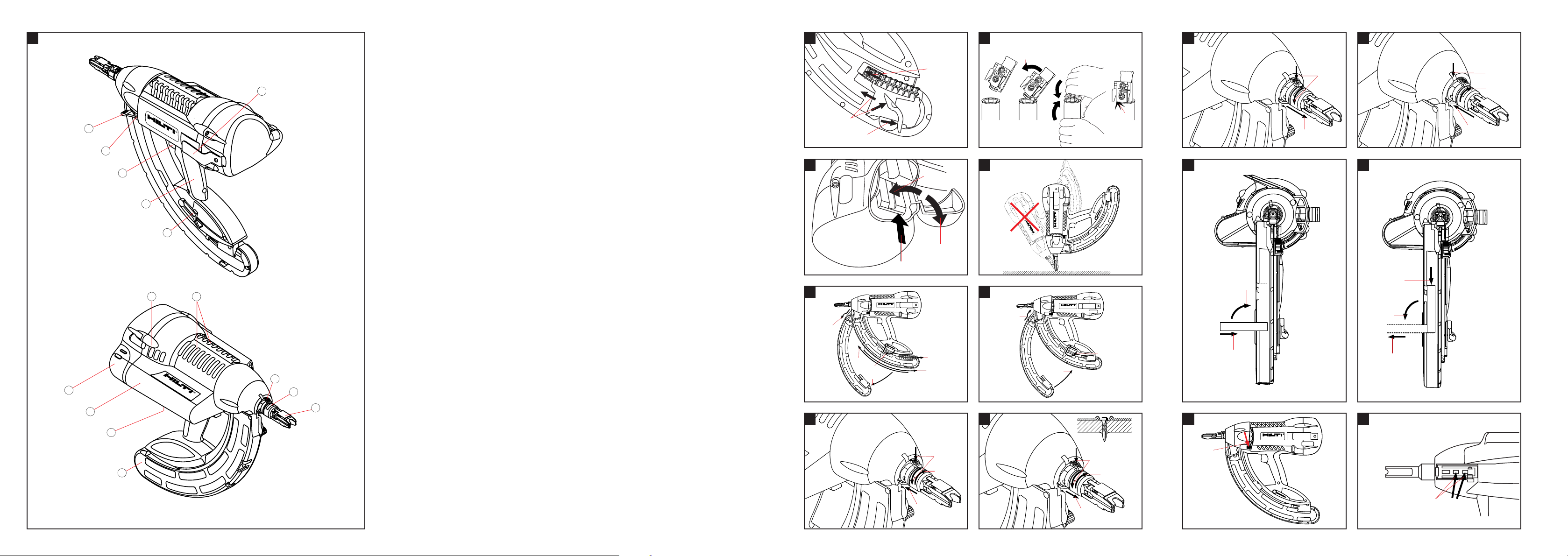
Parts of the tool
Grip
Lockbutton
Nosepiece
Sliding sleeve
Magazine
Type plate
Gas can compartment
Gas can compartment cover
Ventilation slots
Locking lever
Trigger
Reset button
Nail pusher
Belt hook
The numbers refer to the illustrations. The illustrations can be found on the fold-out cover pages. Keep
these pages open while you read the operating instructions.
In these operating instructions, the designation “the tool”
always refers to the GX 100 gas-powered fastening tool.
Location of identification data on the tool
The type designation and serial number are printed on
the type plate on the tool. Make a note of this information in your operating instructions and always refer to it
when making an enquiry to your Hilti representative or
service department.
Type: GX100
Serial no.:
Warning signs
General
warning
Warning:
explosive substance
Warning:
hot surface
Obligation signs
Wear a hard
hat
Wear ear
protection
Wear eye
protection
Read the operating
instructions before
use.
Symbols
1. General information
1.1 Signal words and their meaning
-WARNING-
The word WARNING is used to draw attention to a potentially dangerous situation which could lead to severe personal injury or death.
-CAUTION-
The word CAUTION is used to draw attention to a potentially
dangerous situation which could lead to minor personal injury or damage to the equipment or other property.
-NOTE-
The word NOTE is used to indicate instructions and other useful information. It is not used to indicate potentially
dangerous situations or situations where damage may
occur.
1.2 Pictograms
Page 4

14
en
2. Description
The tool is designed for driving specially manufactured
nails (fasteners) into concrete, steel and other materials
suitable for the direct fastening technique (please refer
to the Fastening Technology Manual). The piston principle employed ensures maximum operating safety and
fastening reliability. Gas is used as a propellant.
The tool, gas can and fasteners form a single technical
unit. This means that the tool can achieve optimum fastening performance only when used in conjunction with
the Hilti fasteners and gas cans specially designed and
manufactured for it. The fastening and application recommendations given by Hilti apply only when these conditions are observed.
2.1 Piston principle
The energy from the propellant charge is transferred to
a piston, the accelerated mass of which drives the fastener into the base material. As approximately 95 % of
the kinetic energy is absorbed by the piston, the fastener is driven into the base material at much reduced veloc-
3. Accessories and consumables
Gas can GC 11
Nosepiece X-100TN
Magazine X-GM40
Support X-100SL
Nails Length In magazine strips of Suitable base materials
X-EGN 14 MX 14 mm (1/2″) 10 Steel
X-GHP 18 MX 18 mm (11/16″) 10 Hard concrete / pre-cast concrete / steel
X-GN 20 MX 20 mm (
3
/4″) 10 Concrete / masonry with plaster coating (1cm) /
sand-lime blocks / concrete blocks
X-GN 27 MX 27 mm (1″) 10 Concrete / masonry with plaster coating (1cm) /
sand-lime blocks / concrete blocks
X-GN 32 MX 32 mm (1
1
/4″) 10 Concrete / masonry with plaster coating (1cm) /
sand-lime blocks / concrete blocks
X-GN 39 MX 39 mm (1
9
/16″) 10 Concrete / masonry with plaster coating (1cm) /
sand-lime blocks / concrete blocks
ity (less than 100 m/sec.) in a controlled manner. The
fastener driving process ends when the piston reaches
the end of its travel. This makes dangerous through-shots
virtually impossible when the tool is used correctly.
2.2 Drop-firing safety device
The drop-firing safety device is the result of coupling the
firing mechanism with the cocking movement. This prevents the tool from firing when dropped onto a hard surface, no matter at which angle the impact occurs.
2.3 Trigger safety device
The trigger safety device ensures that a fastener cannot
be driven simply by pulling the trigger only. The tool must
be pressed against a firm surface before a fastener can
be released.
2.3.1 Contact pressure safety device
The tool can be fired only when pressed against a firm
surface with a significant force.
Page 5
4. Technical data
Tool with magazine and gas can
Weight 3.95 kg (8.7 lbs)
Dimensions (L×W×H) 425×172×370 mm (163/4″×63/4″×141/2″)
Nail length max. 39 mm (19/16″)
Nail diameter 3.0 mm and 2.6 mm (.118 and 102 in.)
Magazine capacity 40 + 2 nails
Contact movement approx. 36 mm (17/16″)
Contact pressure approx. 120 N (27 lbs)
Operating temperature range / ambient temperature –5°C to 45°C (23°F to 113°F)
Max. fastener driving rate 600 per 30 min.
1000 per hour
3000 per day
Noise information (applicable to 1mm sheet metal on B45 concrete):
1b) Noise (power) level L
WA, 1S
109 dB (A)
Workplace-relevant emission value L
pAImax
102 dB (A)
(measured at operator ear level)
1e) Noise (pressure) level L’
–
pA, 1s
96 dB (A)
(Variations in operating conditions may cause deviation from these noise emission values.)
Gas can
Capacity 1 can for 750 nails
Recommended transport and storage temperature +5°C to +25°C (41°F to 77°F)
The can is pressurized.
Avoid prolonged exposure to direct sunlight and temperatures above 50°C (122°F).
Substances contained Dimethyl ether, isobutane, propylene,
propane, butane, ethanol and isoparaffin
Can Not refillable
Right of technical changes reserved.
15
en
5. Safety precautions
5.1 Basic safety instructions
In addition to the safety precautions listed in the individual sections of these operating instructions, the following points must be strictly observed at all times.
5.2 Use as intended
The tool is intended mainly for professional use. It designed
for driving nails into concrete, steel, sand-lime block,
concrete block masonry and masonry with a plaster or
cement rendering finish when installing drywall partitions and for other suitable fastening applications in the
construction industry and associated trades.
● Manipulation or modification of the tool is not per-
missible.
● To avoid the risk of injury, use only original Hilti acces-
sories and consumables.
● Observe the information printed in the operating instruc-
tions concerning operation, care and maintenance.
● Never point the tool at yourself or at any bystander.
● Never press the nosepiece of the tool against your hand
or other part of your body (or other person’s hand or
parts of their body).
● Do not attempt to drive fasteners into unsuitable mate-
rials:
- Materials that are too hard, e.g. welded steel and cast
iron
- Materials that are too soft, e.g. wood and drywall
panel
- Materials that are too brittle, e.g. glass and ceramic
tiles
Driving a nail into these materials may cause the nail
to break, shatter or to be driven right through.
Page 6

16
en
● The tool and its ancillary equipment may present haz-
ards when used incorrectly by untrained personnel or
not as directed.
● Pull the trigger only when the nosepiece of the tool is
in contact with the base material.
● Always hold the tool securely, perpendicular to the
work surface. This will reduce the possibility of the nail
ricocheting off the work surface.
● Never redrive a fastener. This may cause the fastener
to break or shatter.
● Never drive a fastener into an existing hole, except as
recommended by Hilti.
● Always observe the application guidelines.
5.3 Take the necessary precautions to make the
workplace safe
● Wear non-slip shoes and always ensure that you have
a secure stance.
● Avoid unfavorable body positions.
● Do not expose the tool to rain or snow and do not use
it in wet or damp environments or in the vicinity of
inflammable liquids or gasses.
● Ensure that the working area is well lit.
● Objects which could cause injury should be removed
from the working area.
● The tool is for hand-held use only.
● Keep the arms flexed when the tool is fired (do not
straighten the arms).
● Keep other persons, children in particular, outside the
working area.
● Before using the tool, make sure that no one is stand-
ing behind or below the point where fasteners are to
be driven.
● Keep the grip dry, clean and free from oil and grease.
5.4 General safety precautions
● Operate the tool only as directed and only when it is in
faultless condition.
● Never leave the tool unattended when it is loaded.
● Always unload the tool before beginning cleaning, ser-
vicing or changing parts and before work breaks (remove
the gas can and nails).
● When not in use, the tool must be unloaded and stored
separate from the gas can in a dry, locked place or
where it is out of reach of children.
● Remove the gas can before transporting the tool.
● Do not use the tool if parts of it are damaged or bro-
ken.
5.4.1 Mechanical
● Use only nails that have been approved for use with
the tool.
● Do not load nails into the magazine when it is not cor-
rectly attached to the tool. The nails may be forcibly
ejected.
5.4.2 Thermal
● Allow the tool to cool when it becomes hot.
● Do not exceed the maximum fastener driving rate (num-
ber of fasteners driven per given time interval). The
tool may otherwise overheat.
5.4.3 Gas
-WARNING-
Liquid gas under pressure.
Observe the hazard warnings and first-aid instructions
printed on the gas can.
The gas is highly inflammable (contains dimethyl ether,
isobutane, propene, propane, butane, ethanol and isoparaffin).
The gas can cannot be refilled.
● Do not use a gas can if it has been damaged.
● Do not attempt to open a gas can.
● Never spray the gas toward persons or animals.
● Keep the gas away from all sources of ignition such as
naked flames, sparks, pilot lights, static discharge and
very warm surfaces.
● Do not smoke while using the tool.
● Do not attempt to force the gas can open. Do not incin-
erate or crush the can and do not attempt to reuse it
for any other purpose.
Storage
● Do not store gas cans in inhabited rooms or in rooms
connected to inhabited rooms.
● Store the gas cans in a dry, well-ventilated place.
● Store the gas cans out of reach of children.
● Do not expose gas cans to direct sunlight or temper-
atures above 50°C (122°F).
● Recommended storage temperature: 5°C to 25°C (41°F
to 77°F).
First aid
-WARNING-
● Direct skin contact with the liquid gas may cause
chilblains or a serious freezing injury similar to a burn.
● If the gas has been inhaled, the person affected should
be taken into the open air and brought into a comfortable position.
● In case of unconsciousness, bring the person affect-
ed into a secure recovery position. Should the person
stop breathing, apply artificial respiration and supply
oxygen if necessary.
● In case of gas contact with the eyes: Rinse the open
eyes under running water for one minute.
Page 7

17
en
● In case of gas contact with the skin: Wash the contact
surface carefully with warm water and soap and apply
a skin cream when dry.
● Consult a doctor if necessary.
5.5 Requirements to be met by users
● The tool is intended for professional use.
● The tool may be operated, serviced and repaired only
by authorized, trained personnel. This personnel must
be informed of any special hazards that may be encountered.
● Always concentrate on your work. Proceed carefully
and do not use the tool if your full attention is not on
the job.
5.6 Personal protective equipment
● The operator and other persons in the immediate vicin-
ity must always wear eye protection, a hard hat and
ear protection while the tool is in use or when checking the tool in case of a fault.
5.7 Safety devices
● Never use the tool if the sliding sleeve (safety device)
is damaged or missing.
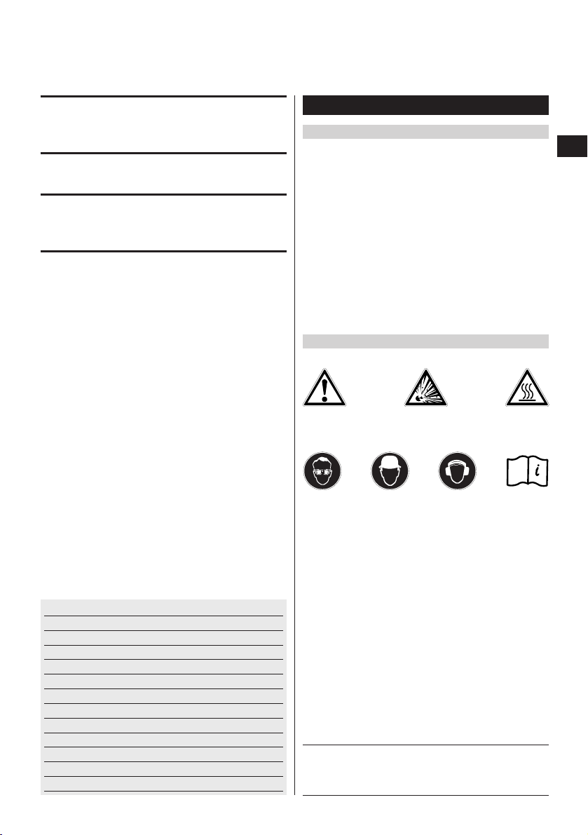
6. Before use
-WARNING-
The magazine must be empty.
The gas can must be removed from the can compartment.
6.1 Inserting nails
1. Pull the nail pusher back until it engages.
-NOTE-
The nail pusher must engage.
2. Slide the nails into the magazine (maximum of 4 strips
of 10 nails).
3. Disengage the nail pusher and allow it to slide forward
slowly.
6.2 Preparing the gas can for use
1. Position the valve head on the inside edge of the gas
can.
2. Press the valve head onto the valve seat until it engages.
-NOTE-
Check that the valve head is fitted correctly on the valve
seat. Slight play is normal.
-CAUTION-
Once the valve head has been fitted to the valve seat on
the gas can it should not be removed (except when the
can is disposed of).
6.3 Inserting the gas can
1. Open the cover of the gas can compartment on the
tool.
2. Slide the gas can into the can compartment, base first,
until it engages.
-NOTE-
The arrow on the valve head must point to the outside
and the white plate must be positioned toward the tool.
3. Close the cover of the gas can compartment and ensure
that it engages in the closed position.
Page 8

18
en
-WARNING-
● Driving the nail may cause flying frag-
ments.
● Flying fragments may injure parts of
the body or the eyes.
● Wear eye protection and a hard hat.
GX 100
R
-WARNING-
● Making the tool ready to fire by press-
ing it against a part of the body (e.g.
the hand) is not permissible.
● This could cause a nail to be driven
into a part of the body.
● Never press the tool against a part of
the body.
-CAUTION-
● The nail is driven by the energy released
on ignition of a gas-air mixture.
● An excessively high noise level may
damage the hearing.
● Wear ear protection.
7. Operation
-NOTE-
When holding the tool with the second hand, care must
be taken to position the hand so that no ventilation slots
or openings are covered.
-CAUTION-
Never attempt to redrive the same fastener.
7.1 Operation
-NOTE-
The magazine must contain at least 2 nails, otherwise no
nail can be driven.
1. Hold the tool at right angles to the work surface and
then press it against the surface as far as it will go.
2. Drive the fastener by pulling the trigger.
7.2 The magazine
-NOTE-
The tool must be unloaded each time before the magazine is changed (see 7.6).
7.2.1 Removing the magazine
1. Pull the nail pusher back until it engages.
-NOTE-
The nail pusher must engage correctly.
2. Remove all nails from the magazine.
3. Disengage the nail pusher and allow it to slide forward
slowly.
4. Push the locking lever down toward the magazine.
5. Swing the magazine forwards away from the tool.
6. Detach the magazine from the tool.
7.2.2 Fitting the magazine
1. Attach the front end of the magazine to the tool.
-NOTE-
The locking lever must be in the open position.
2. Swing the magazine toward the tool, taking care to
ensure that its contours match the shape of the tool.
3. Close the locking lever and check that it engages
securely.
7.3 Adjusting the fastener driving depth at the
nosepiece of the tool
-NOTE-
● When the red ring is not visible, the nosepiece is set
to the standard fastener driving depth (standard setting for fastening wood to concrete).
● When the red ring is visible, the nosepiece is set to a
reduced fastener driving depth.
● When the red ring is visible and the nail is still driven
to deeply, it may be necessary to use a longer nail.
7.3.1 Setting the standard fastener driving depth
1. Press the lockbutton and turn the nosepiece of the tool
in the opposite direction to the arrow.
2. Slide the nosepiece toward the tool.
3. Turn the nosepiece in the direction of the arrow until
it engages.
-NOTE-
The red ring must not be visible.
7.3.2 Setting the reduced fastener driving depth
- NOTE -
This setting is suitable for fastening thin sheet metal to
soft materials (e.g. young / green concrete).
1. Press the lockbutton and turn the nosepiece of the tool
in the opposite direction to the arrow.
2. Slide the nosepiece away from the tool.
3. Turn the nosepiece in the direction of the arrow until
it engages.
-NOTE-
The red ring must be visible.
7.3.3 Removing the nosepiece
1. Press the lockbutton and turn the nosepiece of the tool
in the opposite direction to the arrow.
2. While pressing the lockbutton, pull the nosepiece away
from the tool.
Page 9

19
en
7.3.4 Fitting the nosepiece
1. Bring the nosepiece lockbutton into alignment with
the notch on the tool.
2. Slide the nosepiece onto the tool into the desired position.
3. Turn the nosepiece in the direction of the arrow until
it engages.
7.4 Support
7.4.1 Fitting the support
1. Push the support at right angles into the slot in the
magazine.
2. Pivot the support through 90° and engage it in position.
7.4.2 Removing the support
1. Release the support by pressing the spring catch.
2. Pivot the support through 90°.
3. Pull the support away from the magazine at right
angles.
7.5 Bringing the piston into the correct position
-NOTE-
The piston is incorrectly positioned when the nosepiece
of the tool has not extended to its original position after
the tool is lifted away from the work surface.
The piston can be returned to the correct position by
pressing the reset button. Nails can then be driven. In
exceptional cases, the tool may fire without driving a nail
when the tool is actuated for the first time after it has
been reset.
1. Press the reset button (the direction of movement is
downwards at a slight angle).
7.6 Unloading the tool
1. Open the cover of the gas can compartment.
2. Release the gas can by pressing the valve head in the
direction of the arrow.
3. Remove the gas can from the compartment.
-CAUTION-
Once the valve head has been fitted to the valve seat
on the gas can it should not be removed (except when
the can is disposed of). Place the gas can complete
with valve head in the toolbox.
4. Close the cover of the gas can compartment.
5. Pull the nail pusher back until it engages.
-NOTE-
Ensure that the nail pusher engages.
6. Remove the nails from the magazine.
7. Disengage the nail pusher at the magazine and allow
it to slide forward slowly.
7.7 Application guidelines
For more detailed information, please ask the Hilti marketing organization in your country for a copy of the Hilti
Fastening Technology Manual or the applicable national
regulations.
Concrete
A = min. distance from edge = 70 mm (2
3
/4″)
B = min. fastener center spacing = 80 mm (3
1
/8″)
C = min. base material thickness = 100 mm (4″)
Steel
A = min. distance from edge = 15 mm (
5
/8″)
B = min. fastener center spacing = 20 mm (
3
/4″)
C = min. base material thickness = 4 mm (
5
/32″)
BA
C
BA
ET
C
Page 10

20
en
8. Care and maintenance
-WARNING-
Always remove the gas can and nails from the tool before
performing any work or maintenance on the tool.
8.1 Care of the tool
● Carefully remove any scraps of plastic from the nose-
piece of the tool.
● Never operate the tool if the ventilation slots are blocked.
Clean the ventilation slots carefully with a dry brush.
● Do not permit foreign objects to enter the interior of
the tool.
● Use a slightly damp cloth to clean the outside of the
tool at regular intervals.
● Do not use a spray, steam cleaning system or running
water to clean the tool.
● Always keep the grip surfaces of the tool free from oil
and grease.
● Do not use cleaning agents containing silicone.
● Do not use Hilti spray or similar lubricants.
-CAUTION-
● Do not damage the nail detector
8.2 Maintenance
Check all external parts of the tool for damage at regular
intervals and check that all operating controls function
faultlessly. Do not operate the tool when parts are damaged or when operating controls do not function faultlessly. The tool should be repaired at a Hilti service center.
9. Troubleshooting
-WARNING-
Always unload the tool (remove the gas can and nails) before checking it for faults.
Problem Possible cause Remedy
Low power (nails not Gas can almost empty Fit a new gas can.
driven deeply enough) Valve head defective Fit a new valve head on a new gas
can.
Foreign object jammed in the area Remove the magazine. Remove the foreign
of the magazine / nosepice object. If the problem persists, have the
(nosepiece does not extend to its tool repaired at a Hilti repair center.
original position after lifting tool
away from work surface or extends
too slowly).
Check axial play at nosepiece:
(should be 1–2 mm).
Operating temperature too low Use a gas can that has been warmed to
room temperature (~20°C / ~68°F)
(Warm the can beforehand in a
trouser pocket or in a warm room.)
-WARNING-
Never heat the gas can on a hot
surface or with a flame.
Piston in wrong position See “Piston in wrong position”.
-CAUTION-
● The tool may get hot when in use.
● You could burn your hands.
● Allow the tool to cool.
8.3 Checking the tool after maintenance
After performing maintenance work on the tool and before
inserting the gas can, check that the sliding sleeve (safety device) is fitted and that it functions correctly (easy
sliding movement).
Page 11

21
en
Piston in wrong position Tool is too hot Free the mechanism by pressing the reset
button . Drive the next nail (the tool may
fire once without driving a nail after resett-
ing). Allow the tool to cool if necessary.
Gas can almost empty Use a new gas can
(fit the valve head to the new can).
Tool doesn’t fire Gas can almost empty Insert a new gas can.
Valve head is defective Fit a new valve head on a new gas can.
Valve head fitted incorrectly / not Fit the valve head to the can correctly.
fully seated
Gas can not inserted correctly in the Insert the gas can in the tool correctly.
tool
Operating temperature too low Use a gas can that has been warmed
to room temperature (~20°C / ~68°F)
Ferromagnetic foreign objects Remove foreign objects from the
adhering to the magazine magazine.
Magazine is defective Try using another magazine.
Valve head does not dispense the Remove the gas can and allow it to
correct gas quantity cool or operate the valve head manually
several times (press the white plate toward
the valve head) until it functions correctly.
-WARNING-
Never point the nozzle toward persons, animals, naked flames or hot objects).
Electronics defective If electronics are defective, no
immediate remedy is possible. Have
the tool repaired at a Hilti repair center.
-CAUTION-
Wait 10 seconds and then, if possible, remove the gas can and valve head from the tool before manipulating the
tool as described in the instructions below (*).
Nail jammed in the Several nails driven on top of each * Remove the magazine and nosepiece and
fastener guide other pull the nail out toward the front.
* Remove the nosepiece and tap the nail
back with a hammer and pin punch.
Nail jammed in the Nail has become jammed during * Remove the magazine.
“guide” (steel part the driving operation Remove the nail.
of the magazine)
Tool cycling mechanism Piston in wrong position * See “Piston in wrong position”
jammed (no movement of Nail jammed under the button * Remove magazine, remove nail.
nosepiece after lifting tool -CAUTION-
away from work surface) Do not damage the button and nail detector
Nail detector jammed (possibly * Pull the nosepiece forward
due to dirt or debris) by hand or use pliers.
Trigger jammed in rearmost position * Bring the trigger into its outset
position (by hand or use pliers).
Loose nails / foreign objects * Remove the magazine, remove
under the cover foreign objects. Have the tool
repaired at a Hilti repair center.
Gas can cannot be Tool cycling mechanism jammed Remove the magazine. Remove the nail.
removed Open the cover of the gas can compartment
and press the valve head toward the outside,
in the direction of the arrow, until the valve
head is released from the can. Remove the
valve head and the gas can individually.
Page 12

22
en
Magazine: Dirt or debris Clean from the outside.
Nail pusher jammed
Foreign objects Remove foreign objects from the outside.
Magazine cannot be fitted Rubber buffer on the magazine Replace the rubber buffer.
retaining piece is missing
Locking lever not turned all the way Turn the locking lever all the way
down (90°) down (90°).
Tool cannot be pressed Magazine empty, or possible only 1 Load the magazine.
against the work surface or 2 nails in the magazine
(cycling movement) Tool pressed against a foreign object Press the tool against an unobstructed
surface.
Plastic debris jammed in the Remove plastic debris.
nosepiece
Nail pusher engaged in rearmost Release the nail pusher.
position
Nail pusher jammed Free the nail pusher, clean the magazine /
remove foreign objects
Sleeve turned out of position, not Bring sleeve into correct position.
engaged
Gas can not fitted correctly in the Fit the gas can correctly.
tool
Nail has slid forward in fastener Remove the magazine and remove the
guide nail.
Loose nails or foreign objects under Remove the magazine, remove
the cover foreign objects. Have the tool
repaired at a Hilti repair center.
Nosepiece doesn’t engage Lockbutton broken or deformed Fit a replacement nosepiece. Have the tool
repaired at a Hilti repair center.
Leakage from the gas can Faulty interface between gas can and Remove the gas can, remove the valve
or leakage at the interface valve head head from the can and dispose of both
between the can and the parts. Use a new gas can fitted with a
valve head new valve head.
Please send the tool to a Hilti repair center if these measures fail to remedy the problem.
Page 13

23
en
10. Disposal
Most of the materials from which Hilti tools are manufactured can be recycled. The materials must be correctly
separated before they can be recycled. In many countries, Hilti has already made arrangements for taking back
your old fastening tools for recycling. Please ask your Hilti customer service department or Hilti sales representative for further information. Please observe regional and international guidelines and regulations.
Separate the individual parts as follows:
Component / assembly Main material Recycling
Toolbox Plastic Plastics recycling
Tool casing Plastic / synthetic rubber Plastics recycling
Battery Battery recycling
(-NOTE- (observe specific national regulations)
The battery is designed to last the life of the tool.)
Electronics parts Various Electronics scrap
Screws, small parts Steel Scrap metal
Valve head Plastic Plastics recycling
Gas can Disposal of gas cans by incineration (at a
garbage incineration plant) is not permissible. Do not dispose of gas cans with other
scrap for recycling.
11. Warranty
Hilti warrants that the tool supplied is free of defects in
material and workmanship. This warranty is valid as long
as the tool is operated and handled correctly, cleaned
and serviced properly and in accordance with the Hilti
operating instructions, all warranty claims are made within 12 months (unless other mandatory national regulations prescribe a longer minimum period) from the date
of sale (invoice date) and the technical system is maintained. This means that only original Hilti consumables,
components and spare parts may be used in the tool.
This warranty provides the free-of-charge repair or replacement of defective parts only. Parts requiring repair or
replacement as a result of normal wear and tear are not
covered by this warranty.
Additional claims are excluded, unless stringent
national rules prohibit such exclusion. In particular,
Hilti is not obligated for direct, indirect, incidental or
consequential damages, losses or expenses in connection with, or by reason of, the use of, or inability to
use the tool for any purpose. Implied warranties of
merchantability or fitness for a particular purpose are
specifically excluded.
Send the tool and/or related parts immediately upon discovery of a defect to the local Hilti marketing organisation for repair or replacement.
This constitutes Hilti’s entire obligation with regard to
warranty and supersedes all prior or contemporaneous
comments and oral or written agreements concerning
warranties.
11.1 Gas can
Observe the use-by date for the gas can (printed on the
edge of the can).
Page 14

24
en
12. CE declaration of conformity
We declare, on our sole responsibility, that this product
complies with the following standards or standardization documents: 75/324/EWG, 91/155/EWG, 67/548/EWG,
EN 292, EN 792-13, EN 563, EN 50081-2, EN 60529,
EN 1127-1, EN 417, EN 61000-4-3, EN 55011:1998,
EN 61000-6-2:2001, IEC 61000-6-2:1999, EN 61000-63:2001, IEC 61000-6-3:1996, CISPR11:1997.
Designation: Gas-powered fastening tool
Type: GX100
Year of design: 2002
Hilti Corporation
Raimund Zaggl Dr. Walter Odoni
Senior Vice President Vice President Development
Business Area Direct Fastening Business Unit Direct Fastening
January 2003 January 2003
 Loading...