

Page 1

Ferroscan System FS10
Bedienungsanleitung
Operating instructions
Page 2

16
Contents Main functions
1. Safety / care and maintenance . . . . . . . . . . . . . . . . . . . . . . . . . . . . . . . . . . . . . . . . . 17
2. Items supplied. . . . . . . . . . . . . . . . . . . . . . . . . . . . . . . . . . . . . . . . . . . . . . . . . . . . . . 18
3. Preparing the system for operation . . . . . . . . . . . . . . . . . . . . . . . . . . . . . . . . . . . . . 18
4. Operation . . . . . . . . . . . . . . . . . . . . . . . . . . . . . . . . . . . . . . . . . . . . . . . . . . . . . . . . . . 19
4.1 RV10 monitor . . . . . . . . . . . . . . . . . . . . . . . . . . . . . . . . . . . . . . . . . . . . . . . . . . . . . . . 19
Operating controls . . . . . . . . . . . . . . . . . . . . . . . . . . . . . . . . . . . . . . . . . . . . . . . . . . . . 19
Function keys . . . . . . . . . . . . . . . . . . . . . . . . . . . . . . . . . . . . . . . . . . . . . . . . . . . . . . . 19
Display . . . . . . . . . . . . . . . . . . . . . . . . . . . . . . . . . . . . . . . . . . . . . . . . . . . . . . . . . . . . 19
4.2 RS10 scanner . . . . . . . . . . . . . . . . . . . . . . . . . . . . . . . . . . . . . . . . . . . . . . . . . . . . . . . 20
4.3 Paper reference grid and ruler . . . . . . . . . . . . . . . . . . . . . . . . . . . . . . . . . . . . . . . . . . . 20
4.4 TCU12H charger . . . . . . . . . . . . . . . . . . . . . . . . . . . . . . . . . . . . . . . . . . . . . . . . . . . . . 21
4.5 RB10 battery . . . . . . . . . . . . . . . . . . . . . . . . . . . . . . . . . . . . . . . . . . . . . . . . . . . . . . . 22
5. Using the system. . . . . . . . . . . . . . . . . . . . . . . . . . . . . . . . . . . . . . . . . . . . . . . . . . . . 23
5.1 Setup . . . . . . . . . . . . . . . . . . . . . . . . . . . . . . . . . . . . . . . . . . . . . . . . . . . . . . . . . . . . . 23
5.2 Scanning an image . . . . . . . . . . . . . . . . . . . . . . . . . . . . . . . . . . . . . . . . . . . . . . . . . . . 23
5.3 Determination of position, coverage and diameter of reinforcement. . . . . . . . . . . . . . . . 25
5.4 Rapid detection and verification of minimum coverage . . . . . . . . . . . . . . . . . . . . . . . . .26
5.5 Identifying, recalling and printing images . . . . . . . . . . . . . . . . . . . . . . . . . . . . . . . . . . .27
5.6 PC software . . . . . . . . . . . . . . . . . . . . . . . . . . . . . . . . . . . . . . . . . . . . . . . . . . . . . . . . .27
6. Working range. . . . . . . . . . . . . . . . . . . . . . . . . . . . . . . . . . . . . . . . . . . . . . . . . . . . . . 28
7. Ferroscan FS10 system - technical data. . . . . . . . . . . . . . . . . . . . . . . . . . . . . . . . . . 29
8. Warranty . . . . . . . . . . . . . . . . . . . . . . . . . . . . . . . . . . . . . . . . . . . . . . . . . . . . . . . . . . 29
The Ferroscan FS10 system provides the following main functions:
● Rapid detection and verification of minimum concrete coverage (see section 5.4).
● Scanning and recording of images, with determination of depth of coverage and diameter of
reinforcement (see sections 5.2 and 5.3).
● Printing out of images (see section 5.5).
● PC software for data evaluation (see section 5.6)
Right of technical modifications reserved
Page 3

17
1. Safety / care and maintenance
Safety precautions Ferroscan System Safety precautions TCU12 H
Important: The following safety precautions must be
observed
● The mains supply must correspond to the information printed
on the rating plate. 230 volt units may also be connected to a
220 volt supply.
● Only Hilti RB10 batteries should be charged using this charger.
The TCU12H charger and RB10 battery have been designed to
work together optimally.
● The charger must be able to give off heat during the charging procedure. Please ensure that the ventilation slits are not
obstructed.
Do not use the charger in closed containers!
● Do not short circuit the contacts.
● The charger should be located in a dry, clean and cool place
but protected from frost.
As this unit is connected to the mains supply, safety precautions
must be observed.
Care and maintenance
Always disconnect the mains plug from the mains supply before
cleaning or servicing the TCU12 H. The contacts in the battery
compartment must be kept clean (free of oil and grease).
The ventilation slits must be free of dirt and dust.
A damaged supply cord must be replaced by a Hilti repair centre, as special tools are required for carrying out the repair correctly.
Safety precautions RB1O
Important: The enclosed safety precautions must be
observed
● Before operating the unit, check that the RB10 battery has
been fitted securely.
● Do not continue to operate the unit until the RB 10 battery
becomes totally exhausted (unit completely inoperative). The
battery cells may suffer damage if completely discharged.
● The BP 10 battery should be stored in a dry place and protected from frost. Heat sources such as direct sunlight or radiators should be avoided.
● The RB10 battery should be used only in the units indicated
by Hilti. Use only the charger specified by Hilti for charging the
RB10 battery.The charger,battery and other units of the system
are designed to work together optimally.
● If necessary, clean the RB10 battery terminals before inserting it into the charger or into the unit.
● Do not short circuit the RB10 battery terminals.
● New RB 10 batteries or batteries which have not been used
for a long period only reach full capacity after several
charge/discharge cycles.
Care and maintenance
Battery terminals must be kept clean (free of oil and grease). If,
after having been subjected to considerable use, battery capacity drops below an acceptable level, we recommend that the
battery is checked by Hilti.
Important: RB10 batteries which have reached the end of their
life should be returned to Hilti for recycling.
Important: The following safety precautions must be
observed
● A qualified technical expert (e.g. civil engineer) must be
consulted when making use of the measurement data for
safety relevant purposes (e.g. structural design).
Care and maintenance
The Ferroscan FS10 system is a testing instrument. Although it
has been designed for arduous jobsite conditions (impact and
vibration resistance) it should be treated with the appropriate
care.
The LCD display is suitable for operation in temperatures within
the range –10°C
% to % +50°C. Extreme temperatures resulting from exposure to direct sunlight for long periods and other
sources of heat such as radiators should be avoided!
The PC and printer connections should always be covered when
not in use in order to protect the instrument from the effects of
dust and water spray.
The RS10 scanner required to be recalibrated after a period of
use of approx. two years. It is recommended that the RS10
scanner is returned to the nearest Hilti centre for recalibration
after a period of two years. If the measurement characteristics
lie outside tolerance limits, the complete system becomes inoperative. No further readings can be taken.
The lithium auxiliary battery has a life of approx. six years. It is
recommended that this battery is checked at the two-yearly calibration intervals.
Page 4
18
➜
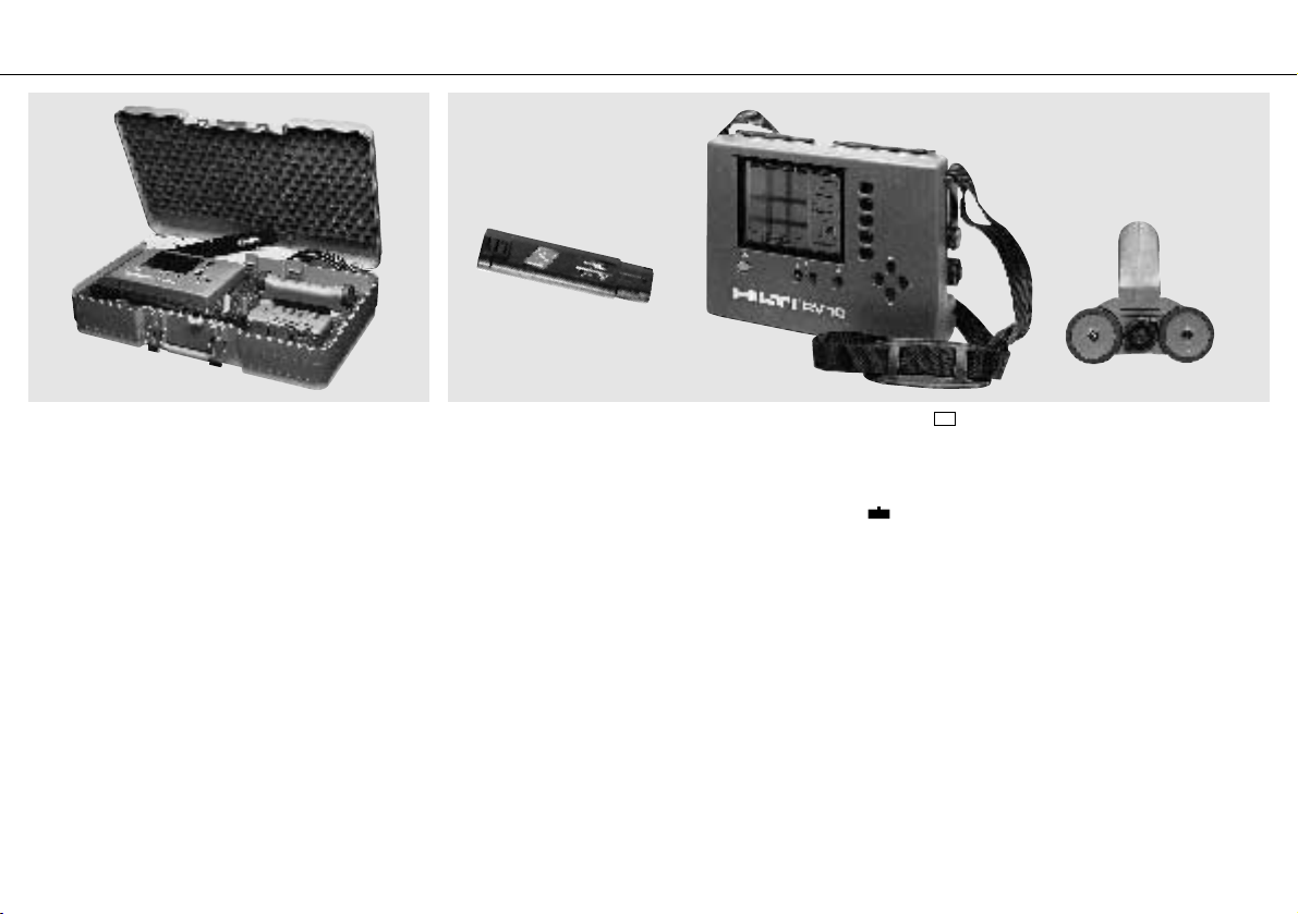
2. Items supplied 3. Preparing the system for operation
The Ferroscan FS10 system is supplied in a standard impactresistant Hilti case. The case contains:
1 RV10 monitor (evaluation module)
1 RS10 scanner (detection probe)
1 RC10 connecting cable
1 RB10 battery
1 TCU12 H charger
10 RG10 paper reference grids
1 roll of adhesive tape
1 serial interface connecting cable
1 PC program for data analysis
Before the system can be operated, the RB10 battery must be
charged using the TCU12 H charger (see section 4.4).
The charged RB10 battery should be inserted in the compartment on the base of the RV10 monitor (locking lever facing
upwards).
Press the button to switch on the RV10 monitor. If the system is being operated for the first time, after running through an
automatic self test, a short description of basic functions
appears on the screen. Alternatively, the last recorded image will
appear on the screen. The battery must be recharged when the
symbol, which appears at the left-hand edge of the screen,
begins to blink. Charge the battery using the TCU12 H charger
(see page 21). The RS10 scanner must be connected to the
RV10 monitor using the RC10 connecting cable before readings
can be taken.
I/O
Page 5
19
6
5
1
7
432
8 9
12
10
11
Scan...
Analyse...
Quickscan...
Set Up...
Main Menu
Delete
Image...
1254 22-OCT-92 09:35
25 of 26
Scan...
Analyse...
Quickscan...
Set Up...
Main Menu
Delete
Image...
"Scan"creates and stores a
600mm square image. Up to 42
images can be stored.
"Analyse"provides detailed
measurement functions for
the stored images.
"Quickscan"gives rapid
assesment of coverage over
a large surface.
"Delete image"removes one
or more images from the
memory.
"Set up"sets volume, time,
date and language.
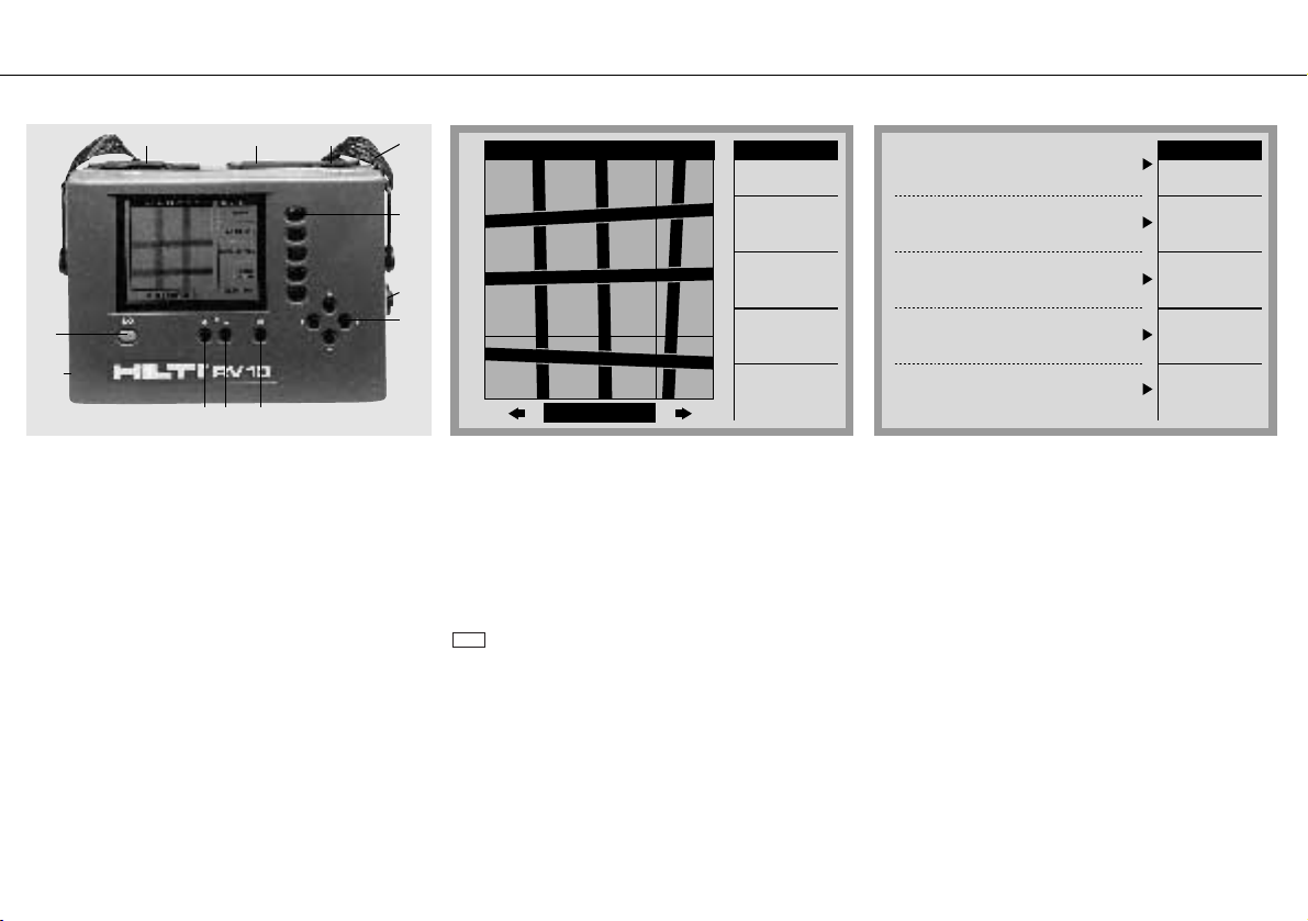
4. Operation
4.1 RV10 monitor
Operating controls
1 On/off button
2 Increase image contrast
3 Reduce image contrast
4 Print
5 Cursor keys
6 Function keys
7 Printer connection
8 PC connection
9 DC power supply socket
10 Scanner connection
11 Battery compartment
12 Carrying strap
Warning: for DC power supply a regulated output voltage of
12 V is required.
Note: To save battery power, the monitor switches off automatically if no button is pressed for a period of 5 minutes.
Function keys
The five function keys are used to select a function from the
main menu which appears on the right-hand side of the screen.
When a function has been selected, the function menu is displayed. If no function is allocated to a particular key, the corresponding position on the screen remains blank. If a function is
not available for a particular operating mode, the menu position
is displayed in grey.
To return to the main menu from a function menu, press the
key.
Done
Display
Normally, when the RV 10 monitor is switched on, the last
recorded image appears on the screen. If no image is stored in
the RV10's memory, a brief description of the main functions is
displayed.
Page 6

20
3
2
1
4
View +
View -
Depth/¿
Done
Analyse
Hide Grid
1254 22-OCT-92 09:35
View Range: o-6o
Depth: 53 ¿: 12
381
312
0 15 30 45 60
015304560
4.3 Paper reference grid and ruler4.2 RS10 scanner
The screen is divided into three main areas.
– The function menu, which can consist of up to five different
functions, is displayed on the right-hand side of the screen. Each
function is activated by selecting the appropriate function key to
the immediate right of the screen.
– At the foot of the screen,the following data is displayed: Righthand side – position of the cursor; left-hand side – depth of coverage and diameter.
– The scanned image is displayed on the main area of the
screen. Each image can be identified by its consecutive number
and date/time, which appears at the top of the screen, and is
recorded with the image in the RV10's memory.
Note: Any additional information relating to the construction site,
position on the structure, etc. must be recorded by the operator
and allocated to the image number.
1 Start/stop button for the scanning procedure
2 Screw for removing the grip
3 Marks for effective scanning width
4 Cable connection
The grip can be removed from the scanner,allowing readings to
be taken where conditions are cramped (e.g. scaffolding close to
the surface to be scanned).
Note: The marks on the left or at the top indicate the start
positions of the scanner rear wheels.
The paper reference grid represents the pre-programmed
600
×600 mm area to be scanned by the Ferroscan RV10 /
RS10.The paper grid, which serves as a direct representation of
the area scanned and for guidance of the RV10 scanner, should
be attached to the surface of the structure using adhesive tape.
If the paper reference grid cannot be attached to the surface of
the structure (due to dampness, dust or dirt), auxiliary means
e.g. a ruler should be used to draw the reference grid directly on
the surface.
Page 7

21
4.4 A TCU12H charger
Preparing the charger for use
1. Connect the charger to the mains supply. The
green LED must light.
2. Insert the RB10 battery into the battery compartment. The battery must engage securely in
the charger.
The charger can be mounted on a wall. (See
wall-mounting holes ➃ on base of charger).
Recommended screws: Round head wood
screws with plastic anchors.
Charging functions
➀ Charger ready LED (green)
The charger ready LED (green) lights continuously when the charger is connected to the
mains supply.
➁ Charging indicator LED (red)
The charging indicator LED (red) lights continously when the RB10 battery is being
charged. The charging indicator LED (red)
blinks (20.5 sec. off, 1 sec. on) after the charger has switched to trickle charge mode.
➂ Battery compartment
In order to ensure correct contact, the RB10
battery engages with a “click” in the battery
compartment. This feature is particularly important when the charger is mounted on a wall.
➃ Wall mounting
Make use of the holes provided on the base of
the charger housing for wall mounting.
Notes on charging procedure
If charging does not begin immediately after
inserting the RB10 battery into the charger,
then the battery is either too cold or too warm.
The battery can remain in the charger. The
charging procedure begins automatically after
the RB10 battery has reached the specified
temperature (0°–45°C). The charger is equipped with an electronic temperature-monitoring
device. Under normal conditions,the RB10 battery is charged after approx. one hour, after
which a trickle charge current counteracts the
battery's inherent tendency to lose its charge.
Technical data
Mains voltage: 110 / 115 / 230 / 240 Volt
Frequency: 50 Hz / 60 Hz
Output current: Charging current 1.6 A
Trickle charge current 80 mA
Charging time: Approx. 1 hour; For 1.4 Ah battery cells
Output voltage: Adapted to NiCd cell charging
characteristics U max. ≈ 17 volts
Weight: 1.5 kg
Supply cord length: 2 m
Indicators: Connected to mains supply – green LED lights
continuously
Charging – red LED lights continuously
Trickle charge – red LED blinks
(20.5 sec. off, 1 sec. on)
➀ Green LED – charger ready
➁ Red LED – charging indicator
➂ Battery compartment
➃ Wall mount
➄ Supply cord
The RB10 battery will suffer no damage
even if left in the charger for long periods.
LED LED
red green
Charger connected to mains
No battery in charger off on
Charger connected to mains
Battery charging on on
Charger connected to mains
Battery is charged blinks on
Charger connected to mains
Battery is too cold or too warm off on
Safety precautions:
See page 17, section 2
Page 8

Technical data
Type of cell: Nickel-cadmium sub C
Number of cells: 10
Capacity: > 1.4 Ah
Nominal voltage: 12 volts DC
Weight: 0.62 kg
Preparing the battery for use
● Charge the RB10 battery before use.
● Always begin work with the system with the battery at room
temperature (max. 40°C).
● Charging only begins when battery temperature is within the
range 0°–45°C. If the battery is too warm, it must be allowed to
cool. The charger begins charging automatically as soon as the
specified temperature range is reached. The battery can remain
in the charger.
Environmental protection / recycling
The RB10 battery contains 10 nickel-cadmium
cells. Not only Hilti but also Hilti customers carry
the responsibility for ensuring that batteries
which have reached the end of their life are
returned for recycling.
● Return used batteries to a Hilti centre for recycling.
● The raw materials, nickel and cadmium, can be extracted
from used Hilti batteries in a special recycling process.
Important: Never dispose of RB 10 nickel-cadmium batteries
with household waste. Do not throw the batteries into a fire or
into water.
22
1 2
➀ RB 10 battery release lever
➁ Contacts
4.5 RB10 battery
Using the battery
1. RB10 battery release lever
Press the release lever to remove the RB10 battery from the
monitor unit.
2. Battery terminals
The battery is charged and provides its power via the two power
terminals (a).
The charger monitors battery cell temperature via the temperature control terminal (b), protecting the battery from damage due
to overheating.
Notes
● The RB10 battery can be recharged more than 1000 times.
● The RB10 battery does not suffer damage even when left in
the charger for long periods.
Safety precautions: See page 17, section 3
Page 9

23
Volume
Time
Date
Done
Set up
Volume:
Time:
Display
Date:
Display:
Use cursor keys
5
16:38
17 -Nov -93
Deutsch
Select item
Set value
1
2
3
4
5 6 7 8
Start
Repeat
Set
Origin
Done
Scan
5. Using the system
5.2 Scanning an image5.1 Set up
The volume of the acoustic signal, the date, the time and the
operating language (German, English, French),can be set by the
operator as desired.
Starting point: Main menu
Press the button. The menu appears at the right-
hand side of the screen.
Select the , , or keys. Language and
unit of measurement (mm/inch) can be set by selecting .
Press the cursor keys to select the day or month.
Press the cursor keys to set the value.
Press the key to return to the main menu.
Done
mi
ko
Display
Display
TimeDateVolume
Set upSet up
Note: As a result of the detection principle utilised, reinforcement which runs parallel to the direction of movement of the
scanner cannot be detected. The grid area must be scanned in
two directions, at right angles to each other.
Note: In order to receive a correct image, it is necessary to follow the prescribed scanning traces in the prescribed sequence.
A) Attach the supplied paper reference grid, using adhesive tape,
to the surface of the concrete. Alternatively, if the condition of the
surface does not allow the use of adhesive tape, the grid can be
marked directly on the concrete using the ruler. Mark out trace
numbers one to eight.
Optimum results will be achieved when the grid axis lies parallel to the reinforcement.
B) Connect the RS10 scanner to the RV10 monitor using the
RC10 connecting cable. Press the button. Press the
key.The starting position of the scanner is shown on the screen
in black.
Scan
I/O
Page 10

24
1
2
3
4
5 6 7 8
Start
Repeat
Set Origin
Done
Scan
0 15 30 45 60
015304560
C) Position the RS10 scanner exactly at the beginning of trace
no. 1 on the grid. Press the start/stop button on the scanner or
the key on the monitor.
Note: Incorrect or inaccurate positioning of the scanner will
result in “shifting” of the image and the indicated location of the
reinforcement will be incorrect. In order to cover the entire area
completely, it must be scanned according to the specified grid,
in vertical and horizontal directions.
Start
Marks are printed on the papier reference grid as an aid to positioning the scanner. If the reference grid is marked directly on
the concrete surface using the ruler, the scanner must be positioned according to the effective scanning width represented by
the grid. Guide the scanner along the trace lines. The distance
covered is displayed on the screen. When the 600 mm trace has
been fully scanned, an acoustic signal is given automatically.
The scan can be interrupted before reaching the end of the 600
mm trace (e.g. because of an obstruction). In this case, the
start/stop button on the scanner or the key on the monitor
must be pressed. The scanned trace is displayed on the monitor
as a shaded area. On the screen, the starting position for the
scanner moves automatically to the next trace.
Stop
D) Repeat the procedure described at C) in the correct order for
the remaining seven traces. The vertical and horizontal scanned
areas are displayed on the screen in black. Press the
function key.The scanned image appears on the screen.
The trace presently being scanned can be interrupted. By pressing the key, the scanner can be returned to the starting
position.
By pressing the key several times, it is possible to move
back and repeat several scan traces.
Note: An image is received only when an area ha been scanned
vertically and horizontally.Areas which have been scanned only
vertically or only horizontally are shown on the screen in grey
and no image is displayed.
Repeat
Repeat
Done
Page 11

25
View +
View -
Depth/¿
Done
Analyse
Hide Grid
1254 22-OCT-92 09:35
View Range: o-6o
Depth: 53 ¿: 12
381
312
The quickscan function provides a quick overview of the position
of the reinforcing bars. The Depth+ and Depth– functions permit the operator to select the depth of coverage. The reinforcing
bars located between the surface and the selected depth of coverage are shown on the screen in a black and white image.
The depth viewed is indicated at the bottom of the screen.
Note
Optimum accuracy of all measurements can be obtained only
when the reinforcing bars are scanned at right angles.
Outset situation: Main menu and image to be evaluated are on
the screen (recalling a recorded image – see section 5.4).
Press function key.
Position the cursor on the desired piece of reinforcement by
using the cursor keys ( ) situated at bottom right
of the screen. The coordinates of the cursor, or respectively, the
reinforcement, are displayed on the right at the bottom of the
screen.
Press the function key. Depth of coverage and diameter (∅) are displayed on the left at the bottom of the screen.
Note: The diameter (∅) is displayed if and only if a reliable read-
ing is allowed for by the detection signals i.e. if the distance
between rebars corresponds to min. twice the coverage and the
reinforcement is not too close to the edge of the image. This
information can be obtained at a depth of coverage of up to 60
mm.
Depth / ∅
miko
Analyse
5.3 Determination of position, depth of coverage and diameter of reinforcement
The unit of the display diameter depends on the scanner used
for the measurement. If the scanner is calibrated for standard
diameters according to american ACI standard (see section 7),
the diameter is shown in standard number #. Otherwise it is displayed in “mm”.
The coordinates of the cursor and the coverage (depth) are in
general displayed in “mm”. If the option “Display” (Engl.: in.) is
chosen (see section 5.1), they will be shown in “in”.
Due to the lack of space available, the units “in.” or “mm” are
not explicitly displayed. The coordinates and the depth in “mm”
are shown in integers. In “in.” they are displayed with a deci-
mal point.
Page 12

26
Start
Depth +
Depth -
Done
Quickscan
Quickscan...
Trigger depth:
Distance:
Coverage:
20
727
30
0
100
Record
5.4 Rapid detection and verification of minimum coverage
Outset situation: Main menu.
– Select function.
– Set minimum coverage
,
keys).
– Position the scanner on the surface.
– Press the start key on the monitor or the button on the scanner.
– Move the scanner along the surface at right angles to the
expected position of the reinforcement.
– An acoustic signal is given each time a reinforcing bar is
detected within the preset minimum coverage range (adjustment of volume – see section 5.1).
– Mark the position of the rebar, using the mark at the free end
of the scanner.
Record function
After pressing the key, depth of coverage data can be
recorded while scanning over a distance of up to 10 m. The
function key can be used to set the maximum
distance to be recorded and direction of movement.
Start/set length
Record
Depth–Depth+
Quickscan
The and keys are used to set the minimum
depth of coverage. When the scan is started, all reinforcing bars
at a depth of up to 100 mm will be recorded. The actual depth
is displayed.
An acoustic signal is emitted when a reinforcing bar is detected
within the set minimum depth of coverage. All reinforcing bars
within this minimum depth of coverage are counted. At the end
of the scan, the number of reinforcing bars detected is displayed
on the screen.
The scan can be interrupted by pressing the button and
continued by pressing the button. Press the key to
end the scan and save the data. If the scanner is moved too
quickly, an error message is displayed on the screen and the
scan is stopped. If this occurs, proceed according to one of the
following alternatives:
– Press the key to abort the present scan.
– Press the key to record the scan up to this point.
Record
Restart
Done
Start
Stop
Depth –
Depth +
Note: Reinforcement which lies parallel to the direction of the
scan cannot be detected. Optimum detection accuracy is
achieved when the scanning direcion is at right angles to the
position of the reinforcement. If the position is not known, an
image of the reinforcement should first be made (see section
5.2).
Start
Tiefe +
Tiefe -
Beenden
Aufnahme
Messweg
Tiefe einstellen
Start/LŠnge
festlegen
†berdeckung
4721
40
78
100
0
0
10
M
Page 13

27
Scan...
Analyse...
Quickscan...
Set Up...
Main Menu
Delete
Image...
1259 22-OCT-92 09:40
30 of 31
The RV10 monitor can store up to 42 images in its memory.
When the monitor is switched on, the last recorded image
appears on the screen automatically. Each image is identified at
the top of the screen by a consecutive number and date/time of
scanning. The number of images in the system's memory is displayed at the foot of the screen.
Two types of image are possible. A picture image records all
data for the reinforcing bars within the area of the scan. This
enables position, depth and diameter to be determined subsequently.A quickscan image records the length of the scan, position and number of bars as well as depth of coverage over the
bars that lie at right angles to the direction of the scan.
Press the cursor keys in order to recall a particular
image.
When the image to be printed appears on the screen:
– connect the printer
– press the key
It is recommended that the operator keeps a systematic record
of the information relating to each image.
k
o
5.5 Identifying, recalling and printing images
Note: To connect the printer a printer cable (36-pin Centronics /
25-pin sub D type) is required. The connected printer must be
compatible to following standard: IBM Proprinter X24, Epson FX
or Diconix 701.
For the printer to work properly the DIP-switches have to be
positionned accordingly (refer to the printer manual).
The Ferroscan PC software permits data to be transferred from
the RV10 to a PC, through the serial interface, for further processing. All data evaluation functions available on the RV10 can
also be carried out on the PC.
Additional functions permit the data and images to be exported
to other PC programs. The printer configured in the Windows
operating system can be used for printing out the data.
Use of the PC program and the functions available are described
in the manual supplied with the software.
Installation under Windows
In the File Manager or Program Manager, type a:\setup. Press
the Enter key and follow the instructions that appear on the
screen.
System requirements
IBM PC or 100% compatible
INTEL 386 processor or higher (486 recommended)
8 MB RAM
2 MB free space on the hard disk
3
1
/2″ floppy disk drive
VGA video adapter (or higher)
Mouse or compatible pointing device
1 free serial interface
MS Windows 3.1 or higher
Windows is a registered trademark of Microsoft Corp., USA.
5.6 PC software
Page 14

28
Max. depth (mm)
for image
processing
Max. depth (mm)
for determination
of coverage
Max. depth (mm)
for determination
of diameter
130
90
60
6
136
94
60
8
142
98
60
10
148
102
60
12
154
106
60
14
160
110
60
16
160
110
60
20
160
110
60
25
164
118
60
28
172
134
60
32
180
150
60
36
d/T 1
± 10%
± 1ø
Resolution/
accuracy
Standard diameters (mm) as per DIN 488
d/T 2
6. Measurement range
* d = distance between reinforcing bars, T = coverage (depth)
The figures given for accuracy apply to the following test conditions:
Smooth surface, circular rebars; permeability range 85–105; reinforcement Iying at right angles
to scanning direction.
Caution: A qualified technical expert (e.g.construction engineer) must be consulted when the
results are to be used for structures where safety is at stake (e.g. structural design).
Diameters (inch) as per ACI standard 318-106
#3 #4 #5 #6 #7 #8 #9 #10 #11
3/8
4/8
5/8
6/8
7/8
1.13
1.27
Max. depth (mm)
for image
processing
Max. depth (mm)
for determination
of coverage
Max. depth (mm)
for determination
of diameter
Max. depth (mm)
for image
processing
Max. depth (mm)
for determination
of coverage
Max. depth (mm)
for determination
of diameter
141
150
160
97
103
110
60
60
60
Diameter (inch) as per CPCI
#10
11.3
150
100
60
1
160
160
160
165
110
110
110
121
60
60
60
#15 #20 #25 #30 #36
25.2
19.5
16.0
160
160
110
110
60
60
173
135
60
60
29.9
170
130
60
1.41
180
149
60
35.7
180
150
60
Resolution/
accuracy
d/T 1
± 10%
d/T 2
Resolution/
accuracy
d/T 1
± 10%
d/T 2
± 1ø
± 1ø
Page 15

29
8. Warranty
Hilti warrants that the tool supplied is free of defects in material and workmanship. This warranty
is valid as long as the tool is operated and handled correctly, cleaned and serviced properly and
in accordance with the Hilti Operating Instructions, all warranty claims are made within 12 months
from the date of the sale (invoice date), and the technical system is maintained. This means that
only original Hilti consumables, components and spare parts may be used in the tool.
This warranty provides the free-of-charge repair or replacement of defective parts only. Parts
requiring repair or replacement as a result of normal wear and tear are not covered by this warranty.
Additional claims are excluded, unless stringent national rules prohibit such exclusion. In
particular, Hilti is not obligated for direct, indirect, incidental or consequential damages,
losses or expenses in connection with, or by reason of, the use of, or inability to use the
tool for any purpose. Implied warranties of merchantability or fitness for a particular purpose are specifically excluded.
For repair or replacement, send tool and/or related parts immediately upon discovery of the defect
to the address of the local Hilti marketing organization provided.
This constitutes Hilti’s entire obligation with regard to warranty and supersedes all prior or contemporaneous comments and oral or written agreements concerning warranties.
Right of technical modifications reserved
7. Ferroscan FS 10 System – technical data
General data
Operating temperature: –10°C bis +50°C
Storage temperature: –20°C bis +60°C
Max. relative humidity: 90%
Dust/water protection: IP 54 (DIN 40 050)
Radio interference suppression: EN 55 011
RV10 monitor
Dimensions: 270×195×80 mm
Weight: 2.2 kg (incl. battery)
Screen: Back-lit LCD 115×86 mm,
320×240 pixels,
9 grey shades
Main battery: 12 V NiCd, at least 4 hours
continuous operation
Automatic switch-off: After 5 minutes without key activity
Auxiliary battery: Lithium
(standard life 6 years)
Permanent image memory: 42 images
Microprocessor: 16 bit
Printer interface: Parallel Centronics
PC interface: Serial RS 232
RS10 scanner
Dimensions: 230×133×140 mm
Weight: 1.0 kg
Effective scanning width: 150mm
Permitted scanning speed: % 0.5 m/s
Microprocessor: 16 bit
Technical data for RB1O battery: See page 22
Technical data for TCU12 H charger: See page 21
 Loading...