

Page 1
DX 76-PTR
*384005*
384005
Hilti Corporation
LI-9494 Schaan
Tel.:+423 /234 2111
Fax: +423/2342965
www.hilti.com
Hilti = registered trademark of Hilti Corp., Schaan W 3249 0308 00-Pos. 1 1 Printed in Liechtenstein © 2008
Right of technical and programme changes reserved S. E. & O.
384005 / C
Bedienungsanleitung de
Operating instructions en
Mode d’emploi fr
Gebruiksaanwijzing nl
Brugsanvisning da
Bruksanvisning no
Bruksanvisning sv
Käyttöohje fi
Lietoßanas pamåcîba lv
Instrukcija lt
Kasutusjuhend et
12
13
11
14
14
18
16
15
15
9
6
8
7
13
Page 2
1
+{
2
3+]+[ 4 5 6 7
8
9
+≠
"±
"≠
"“
+±+“+#+|+Ç
+}
X-76-P-PTR
X-ENP
X-76-P-PTR
ENP2K
1 2
Nail
Nagel
Clou
mm
X-ENP2K X-ENP 19
3.32.7 6 10
> 20
For / Für / Pour
X-ENP2K + X-ENP
* Blue cartridges might be used as well for low strength steel up to 10 mm thickness.
* Für Standard Stahl bis zu einer Dicke von 10 mm können auch blaue Kartuschen verwendet werden.
* Des cartouches bleues peuvent également être utilisées pour de l’acier standard d’une épaisseur jusqu’à 10 mm.
red *
rot *
rouge *
X-ENP2K-20 X-ENP-19
Power regulation to be set according to nail stand-off.
Geräte Leistungseinstellung gemäss Nagelvorstand.
Réglage de la puissance selon l’enfoncement du clou.
green
grün
vert
blue
blau
bleu
black
schwarz
noir
Cartridge
Kartusche
Cartouche
3
1
2
3
4
6
2
1
7
5
8
2
1
9
2
4
3
1
10
5
4
12
1
2
3
11
2
3
1
Page 3
DX 76 PTR direct fastening tool
It is essential that the operating instructions
are read before the tool is operated for the
first time.
Always keep these operating instructions
together with the tool.
Ensure that the operating instructions are
with the tool when it is given to other
persons.
Contents Page
1. General information 17
2. Description 18
3. Accessories, consumables 20
4. Technical data 20
5. Safety instructions 21
6. Before use 23
7. Operation 23
8. Care and maintenance 26
9. Troubleshooting 28
10. Disposal 31
11. Manufacturer’s warranty ‐ tools 31
12. Confirmation of CIP testing 32
1 These numbers refer to the corresponding illustrations. The illustrations can be found on the fold‐out
cover pages. Keep these pages open while studying
the operating instructions.
In these operating instructions, the designation “the
tool” always refers to the DX 76 PTR powder‐actuated
fastening tool.
Parts and operating controls 1
DX 76 PTR tool
MX 76‑PTR fastener magazine
@
Contact pins
;
Protective cap
=
Cycling grip
%
Cartridge strip guideway
&
Loading status control window
(
Power regulation wheel
)
Power regulation indicator
+
Padded end cap
§
Tool casing
/
Grip pad
:
Trigger
·
Piston guide release lever
$
Piston guide
£
Fastener magazine spall guard
|
Fastener stop piece
¡
Ventilation slots
Q
X‑76‑F‑15‑PTR fastener guide
W
Tool spall guard
E
Wearing parts
X‑76‑P‑ENP‑PTR piston
R
X‑76‑P‑ENP2K‑PTR piston
T
Piston brake
Z
en
1. General information
1.1 Safety notices and their meaning
WARNING
Draws attention to a potentially dangerous situation
that could lead to serious personal injury or fatality.
CAUTION
Draws attention to a potentially dangerous situation
that could lead to slight personal injury or damage to
the equipment or other property.
17
Page 4
NOTE
Draws attention to an instruction or other useful
information.
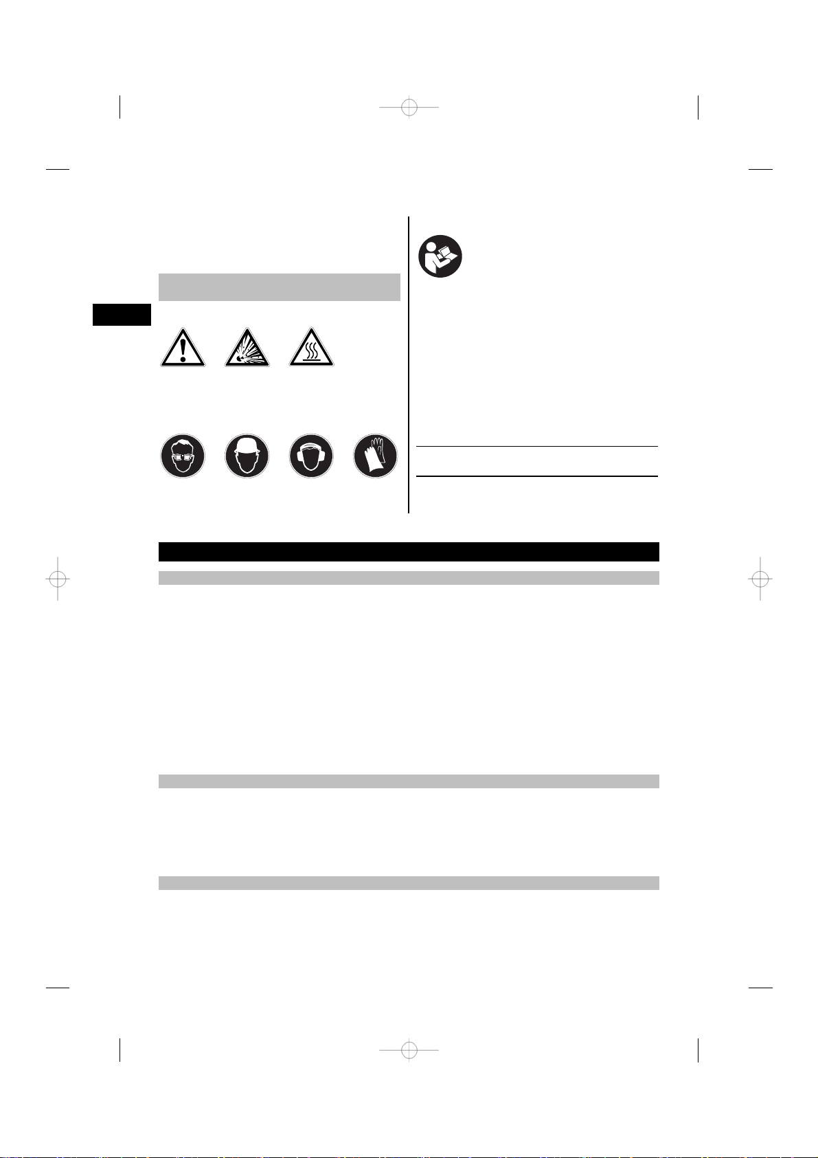
Symbols
1.2 Explanation of the pictograms and other
information
Warning signs
en
Read the
operating
instructions
before use
Location of identification data on the tool
The type designation and serial number can be found
General
warning
Obligation signs
Warning:
explosive
substances
Warning: hot
surface
on the type identification plate on the tool. Make a
note of this data in your operating instructions and
always refer to it when making an enquiry to your
Hilti representative or service department.
Type:
Serial no.:
Wear eye
protection
Wear a hard
hat
Wear ear
protection
Wear
protective
gloves
2. Description
2.1 Use of the product as directed
The tool is intended for use in the construction industry and associated trades for driving fasteners into steel.
The tool is for hand‐held use only.
Modification of the tool is not permissible.
The tool may not be used in an explosive or flammable atmosphere unless it has been approved for use under
these conditions.
To avoid the risk of injury use only genuine Hilti fasteners, cartridges, accessories and spare parts or those of
equivalent quality.
Observe the information printed in the operating instructions concerning operation, care and maintenance.
The tool and its ancillary equipment may present hazards when used incorrectly by untrained personnel or
when used not as directed.
The tool may be operated, serviced and repaired only by trained personnel. This personnel must be informed
of any special hazards that may be encountered.
2.2 Piston principle with piston brake
The energy from the propellant charge is transferred to a piston, the accelerated mass of which drives the
fastener into the base material. Due to use of this piston principle, the tool is classified as a “low velocity
tool”. Approximately 95 % of kinetic energy is taken up by the piston when the tool is fired. As the piston is
always stopped by the piston brake as it reaches the end of its travel, excess energy is absorbed by the tool.
Accordingly, when the tool is used correctly, dangerous through‐shots become virtually impossible.
2.3 Drop‐firing safety device
The drop‐firing safety device is the result of coupling the firing mechanism with the cocking movement. This
prevents the tool from firing when dropped onto a hard surface, no matter at which angle the impact occurs.
18
Page 5

2.4 Trigger safety device
The trigger safety device ensures that a fastener cannot be driven simply by pulling the trigger only. The tool
must be pressed against a firm surface before a fastener can be released.
2.5 Contact pressure safety device
The tool can be fired only when pressed fully against a firm surface with a force of at least 50 N.
2.6 Unintentional firing safety device
The tool is also equipped with an unintentional firing safety device. This prevents the tool from firing if the
trigger is first pulled and the tool then pressed against the work surface. The tool can be fired only when it is
first pressed correctly against the work surface and the trigger subsequently pulled.
2.7 Noise information
As per German legislation (3, GSGV dated January 18, 1991): The noise (power) level LWA,1S as per
§ 1 (2) 1b) applicable to the tool and, due to different workplaces depending on the application for which the
tool is used, also the noise (pressure) level LpAImax at the measurement surface of 1 metre as per § 1 (2) 1e),
are given in addition to the workplace related noise emission value in accordance with the noise measurement
standard. Operating conditions and circumstances of use: most powerful cartridge power load in accordance
with instructions for use with suitable fastener or stud fired vertically downwards into a concrete block and
in accordance with the means of measurement DIN 45635, part 34 “Measurement of the noise emitted by
machines – airborne noise, surface sound transmission – methods – powder‐actuated fastening tools”.
2.8 DX 76 PTR tool: applications and suitable fasteners
Fastening profile metal sheet to steel, steel thickness 6 mm – solid steel
Items required Ordering designation Comments
Fasteners X‑ENP‑19 L15 MX
Fastener magazine MX 76‑PTR
Piston set X‑76‑P‑ENP‑PTR
Fastening profile metal sheet to steel, steel thickness 3‑6mm
Items required Ordering designation Comments
Fasteners X‑ENP2K‑20 L15 MX
Fastener magazine MX 76‑PTR
Piston set X‑76‑P‑ENP2K‑PTR
10 fasteners per magazine
strip
10 fasteners per magazine
strip
en
2.9 DX 76 PTR tool with single fastener guides: accessories, applications and suitable fasteners
Fastening profile metal sheet to steel, steel thickness 6 mm – solid steel
Items required Ordering designation Comments
Fasteners X‑ENP‑19 L15
Fastener guide X‑76‑F‑15‑PTR
Piston set X‑76‑P‑ENP‑PTR
Single fastener
19
Page 6
Fastening profile metal sheet to steel, steel thickness 3‑6mm
Items required Ordering designation Comments
Fasteners ENP2K‑20 L15
Fastener guide X‑76‑F‑15‑PTR
Piston set X‑76‑P‑ENP2K‑PTR
Single fastener
en
3. Accessories, consumables
Hilti toolbox DX 76 PTR KFD, large, with lockable cartridge
compartment
Toolbox for magazine tool
Cleaning set
Protective glasses
Protective glasses
Ear protectors
Hilti spray
Piston and piston brake set X‑76‑P‑ENP‑PTR and X‑76‑P‑ENP2K‑PTR
Spall guard for magazine and single fastener guides
DX 76 PTR test gauge
Cartridge type Ordering designation
Extra heavy 6.8/18 M black
Very heavy 6.8/18 M red
Heavy 6.8/18 M blue
Light 6.8/18 M green
DX 76 PTR
DX 76 / 860‑ENP, Flat brush, 25 mm dia. round
brush, 8 mm dia. round brush, pusher rod, cleaning
cloth
I‑VO 805 PS, clear
I‑VO 808 PS, tinted
Small
4. Technical data
Right of technical changes reserved.
Tool DX 76 PTR
Weight 4.37 kg
Dimensions (L × W × H) 464 mm × 104 mm × 352 mm
Magazine capacity
Contact movement
Contact pressure
Ambient operating temperature range
Maximum average fastener driving frequency*
NOTE
*for trouble‐free operation.
20
10 fasteners
32 mm
90…130 N
-15…+50°C
600/h
Page 7

Noise information with typical application of X‑ENP nail with 6.8/18 M10 blue cartridges and power setting
4 on 8mm steel with 400N/mm²:
Noise (power) level, L
WA, 1S
Workplace‐relevant emission value, L
Noise (pressure) level, L
pA, 1s
pAlmax
119 dB (A)
124 dB (A)
106 dB (A)
5. Safety instructions
5.1 Basic information concerning safety
In addition to the information relevant to safety
given in each of the sections of these operating
instructions, the following points must be strictly
observed at all times.
5.1.1 Personal safety
a) Stay alert, watch what you are doing and use
common sensewhen operating a direct fastening
tool. Do not use tool while tired or under the
influence of drugs, alcohol or medication. A
moment of inattention while operating tools may
result in serious personal injury.
b) Avoid unfavorable body positions. Make sure you
work from a safe stance and stay in balance at
all times.
c) Never point the tool toward yourself or other
persons.
d) Never press the nosepiece of the tool against
your hand or against any other part of your body
(or other person’s hand or part of their body).
e) Keep other persons, especially children, away
from the area in which the work is being carried
out.
f) Keep the arms slightly bent while operating the
tool (do not straighten the arms).
5.1.2 Use and care of powder‐actuated fastening
tools
a) Use the right tool for the job. Do not use the tool
for purposes for which it was not intended. Use it
only as directed and when in faultless condition.
b) Press the tool against the working surface at
right angles.
c) Never leave a loaded tool unattended.
d) Always unload the tool (remove cartridges and
fasteners) before cleaning, before maintenance,
before work breaks and before storing the tool.
e) When not in use, tools must be unloaded and
stored in a dry place, locked up or out of reach
of children.
f) Check the tool or machine and its accessories
for any damage. Guards, safety devices and any
slightly damaged parts must be checked carefully to ensure that they function faultlessly and
as intended. Check that moving parts function
correctly without sticking and that no parts are
damaged. All parts must be fitted correctly and
fulfill all conditions necessary for correct operation of the tool or machine. Damaged guards,
safety devices and other parts must be repaired
or replaced properly at a Hilti service center
unless otherwise indicated in the operating instructions.
g) Pull the trigger only when the toolis fully pressed
against the working surface at right angles.
h) Always hold the tool securely and at right angles
to the working surface when driving in fasteners. This will help to prevent fasteners being
deflected by the working surface.
i) Never redrive a fastener. This may cause the
fastener to break and the tool may jam.
j) Never drive fasteners into existing holes unless
this is recommended by Hilti.
k) Always observe the application guidelines.
l) Use the spall guard when the application per-
mits.
m)Never pull the magazine or fastener guide back
by hand as this could, under certain circumstances, make the tool ready to fire. This could
cause a fastener to be driven into a part of the
body.
en
21
Page 8

5.1.3 Work area safety
a) Ensure that the workplace is well lit.
b) Operate the tool only in well‐ventilated working
en
areas.
c) Do not attempt to drive fasteners into unsuitable
materials: Materials that are too hard, e.g. welded
steel and cast iron. Materials that are too soft, e.g.
wood and drywall panel (gypsum board). Materials
that are too brittle, e.g. glass and ceramic tiles.
Driving a fastener into these materials may cause
the fastener to break, shatter or to be driven right
through.
d) Never attempt to drive fasteners into materials
such as glass, marble, plastic, bronze, brass,
copper, rock, insulation material, hollow brick,
ceramic brick, thin sheet metal (< 2.7 mm), cast
iron or cellular concrete.
e) Before driving fasteners, check that no one is
present immediately behind or below the working surface.
f) Keep the workplace tidy. Objects which could
cause injuryshould be removed fromthe working
area. Untidiness at the workplace can lead to
accidents.
g) Keep the grips dry, clean and free from oil and
grease.
h) Wear non‐skid shoes.
i) Take the influences of the surrounding area into
account. Do not expose the tool to rain or snow
and do not use it in damp or wet conditions. Do
not use the tool where there is a risk of fire or
explosion.
5.1.4 Mechanical safety precautions
damage to the tool and/or unsatisfactory fastening
quality.
b) Use only fasteners of a type approved for use
with the tool.
c) Never fill the magazine with fasteners unless it
is correctly installed onto the tool. The fasteners
could be ejected uncontrollably.
d) Never use worn or damaged piston brakes and do
not attempt to manipulate or modify the piston.
5.1.5 Thermal safety precautions
a) If the tool has overheated, allow it to cool down.
Do notexceed the recommended fastener driving
rate.
b) Always wear gloves if the tool has to be dis-
mantled for cleaning or maintenance before it
has been allowed to cool down.
c) The tool must be allowed to cool down if melting
of the plastic cartridge strip is observed.
5.1.6 Danger of explosion
a) Use only cartridges of a type approved for use
with the tool.
b) Remove the cartridge strip from the tool care-
fully.
c) Do not attempt to forcibly remove cartridges from
the magazine strip or tool.
d) Unused cartridges must be stored in a dry, high
place, locked up or out of reach of children.
5.1.7 Personal protective equipment
a) Select the correct fastener guide and fastener
combination forthe job on hand. Failure to use the
correct combination of these items may result in
22
The user and any other persons in the vicinity must
wear suitable eye protection, a hard hat and ear
protection while the tool is in use or when checking
the tool for faults etc. The user must also wear
protective gloves.
Page 9

DX 76
M
X
7
6
6. Before use
NOTE
Read the operating instructions before the tool is
operated for the first time.
6.1 Check the tool
Check that no cartridge strip is loaded in the tool. If a
cartridge strip is present in the tool, use the cycling
7. Operation
grip to cycle the tool several times until the cartridge
strip projects from the tool at the cartridge strip exit
and it can be pulled out and removed from the tool.
Check all external parts of the tool for damage and
check that all controls operate faultlessly. Do not
operate the tool when parts are damaged or when the
controls do not function correctly. If necessary, have
the tool repaired at an authorized Hilti service center.
Check thepiston and piston brakefor wear and ensure
that the parts have been fitted correctly.
CAUTION
Never redrive a fastener. This may cause the
fastener to break and the tool may jam.
en
1234
DX 76
6
7
X
M
NOTE
When you grip the tool with your other hand, care
must be taken to ensure that this hand does not cover
any ventilation slots or openings.
WARNING
The material may splinter or fragments of the
magazine strip may fly off when the fastener is
driven. The user of the tool and other persons in the
immediate vicinity must wear protective glasses
and a hard hat. Splintering material presents a risk
of injury to the eyes and body.
CAUTION
The fastener driving action is initiated by ignition
of a propellant charge. The user of the tool and
other persons in the immediate vicinity must wear
ear protectors. Exposure to noise can cause hearing
loss.
WARNING
Making the tool ready to fire by pressing it against a
part of the body (e.g. the hand) should never be done.
This could cause a nail or the piston to be driven into
a part of the body. Never press the tool against a
part of the body.
7.1 Operation
Fastening guidelines: These guidelines must be observed at all times.
NOTE
For detailed information, please ask your local Hilti
representative for a copy of the applicable technical
guidelines or national technical regulations.
7.2 Driving fasteners with the magazine tool
If a cartridge fails to fire or misfires, always proceed
as follows:
Keep the tool pressed at right angles against the
working surface for 30 seconds.
If the cartridge still fails to fire, lift the tool away from
the working surface, taking care to avoid pointing it
at yourself or other persons.
Load the next cartridge on the strip by cycling the
tool. Use up the remaining cartridges on the strip and
remove the used cartridge strip from the tool. The
(partly) used cartridge strip must then be disposed of
suitably in order to prevent further use or misuse of
any unfired cartridges.
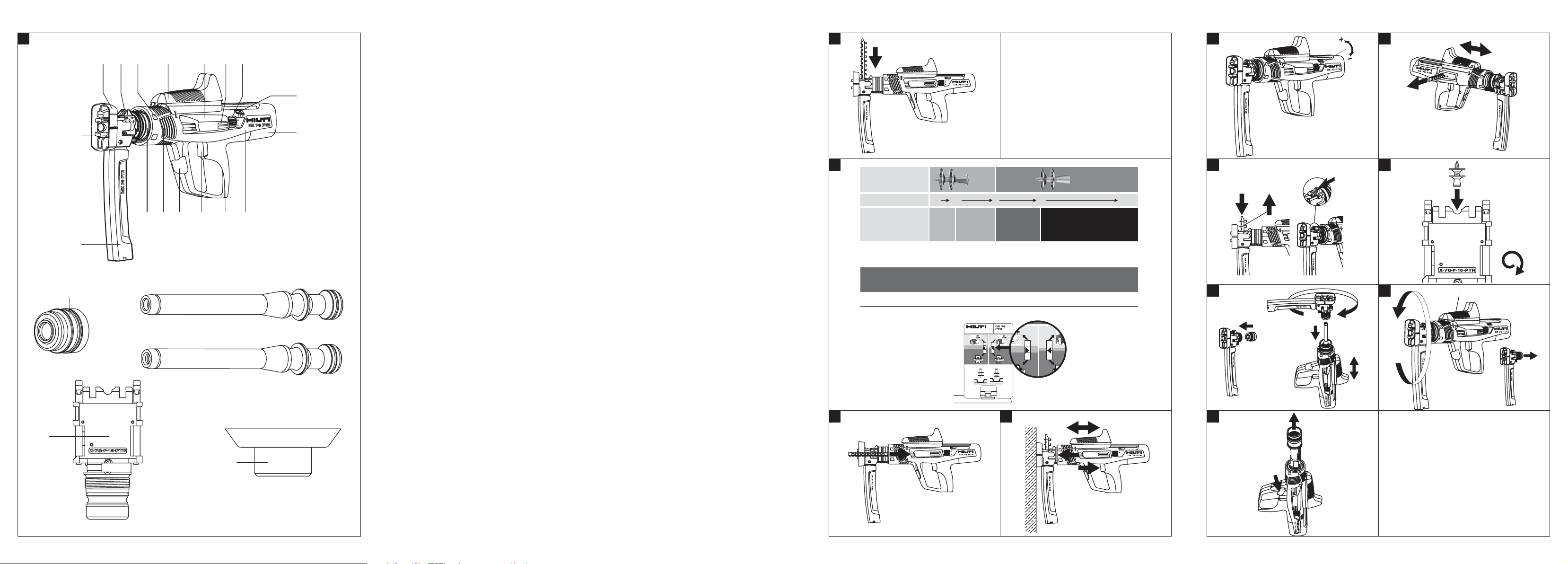
7.2.1 Loading fastener strips in the magazine 2
Push the fastener strip into the magazine from above
until the washer of the final fastener engages in the
magazine.
23
Page 10

7.2.2 Selecting the cartridge 3
1. Determine the thickness of the supporting material.
2. Select a suitable cartridge and power setting according to the cartridge recommendations.
7.2.3 Inserting the cartridge strip 4
en
Push the cartridge strip, as far as it will go, into the
cartridge strip guideway on the side of the tool.
7.2.4 Driving fasteners with the magazine
tool 5
CAUTION
Never drive fasteners into existing holes unless this
is recommended by Hilti.
CAUTION
Never redrive a fastener. This may cause the
fastener to break and the tool may jam.
CAUTION
If the tool has overheated, allow it to cool down. Do
not exceed the recommended fastener driving rate.
1. Press the tool against the working surface at right
angles.
2. Drive the fastener by pulling the trigger.
3. Prepare the tool for driving the next fastener by
pushing the cycling grip back toward the rear of
the tool and then forward to its original position.
7.2.5 Checking and adjusting fastener driving
depth 36
NOTE
Fastener driving depth can be adjusted by turning
the power regulation wheel on the tool. (setting 1 =
minimum; setting 4 = maximum)
1. Use the test gauge to check nail stand‐off.
2. If a fastener is not driven deeply enough, driving power must be increased. Adjust the power
regulation wheel to the next higher setting. If a
fastener is driven too deeply, check to ensure that
supporting material (e.g. a beam) is present at
this point. A fastener should not be driven into
unsupported sheet metal. Check to ensure that
the sheet metal to be fastened lies tightly against
the supporting structure, with no gaps or space
underneath.
3. Drive a fastener.
4. Use the test gauge to check nail stand‐off.
5. If the fastener is still not driven deeply enough
or, respectively, is driven too deeply, steps 2
to 4 must be repeated until the correct depth
is achieved. If necessary, use a cartridge with a
higher or lower power rating.
7.3 Unloading the tool
7.3.1 Removing cartridges from the tool 7
WARNING
Do not attempt to forcibly remove cartridges from
the magazine strip or tool.
1. Advance the cartridge strip through the tool by
moving the cycling grip until the strip is visible at
the exit aperture.
2. Pull the cartridge strip out of the tool at the
cartridge strip exit aperture.
7.3.2 Removing fastener strips from the tool 8
WARNING
Check that no cartridge strip is loaded in the tool. If
a cartridge strip is still present in the tool, operate
the cycling grip until the strip projects from the tool
and then pull the strip out of the cartridge strip exit
by hand and remove it from the tool.
CAUTION
The fastener strip will be ejectedby springpressure.
1. Push the fastener strip 5 mm further into the
magazine and hold it securely in this position.
2. Push the catch forward with the thumb and hold
it in this position.
3. Remove the fastener strip from the magazine.
7.4 Driving fasteners with the single‐fastener
tool (accessories required)
WARNING
Check that the spall guard 19 is fitted to the tool.
7.4.1 Inserting the fastener in the single‐
fastener tool 9
1. Turn the tool so that the fastener guide is pointing
upwards.
2. Insert the fastener in the tool from above.
7.4.2 Selecting the cartridge 3
1. Determine the thickness of the supporting material.
24
Page 11

2. Select a suitable cartridge and power setting according to the cartridge recommendations.
7.4.3 Inserting the cartridge strip 4
Push the cartridge strip, as far as it will go, into the
cartridge strip guideway on the side of the tool.
7.4.4 Driving fasteners with the single‐fastener
tool
CAUTION
Never drive fasteners into existing holes unless this
is recommended by Hilti.
CAUTION
Never redrive a fastener. This may cause the
fastener to break and the tool may jam.
CAUTION
If the tool has overheated, allow it to cool down. Do
not exceed the recommended fastener driving rate.
1. Press the tool against the working surface at right
angles.
2. Drive the fastener by pulling the trigger.
3. Prepare the tool for driving the next fastener by
pushing the cycling grip back toward the rear of
the tool and then forward to its original position.
7.4.5 Checking and adjusting fastener driving
depth 36
NOTE
Fastener driving depth can be adjusted by turning
the power regulation wheel on the tool. (setting 1 =
minimum; setting 4 = maximum)
1. Use the test gauge to check nail stand‐off.
2. If a fastener is not driven deeply enough, driving power must be increased. Adjust the power
regulation wheel to the next higher setting. If a
fastener is driven too deeply, check to ensure that
supporting material (e.g. a beam) is present at
this point. A fastener should not be driven into
unsupported sheet metal. Check to ensure that
the sheet metal to be fastened lies tightly against
the supporting structure, with no gaps or space
underneath.
3. Drive a fastener.
4. Use the test gauge to check nail stand‐off.
5. If the fastener is still not driven deeply enough
or, respectively, is driven too deeply, steps 2
to 4 must be repeated until the correct depth
is achieved. If necessary, use a cartridge with a
higher or lower power rating.
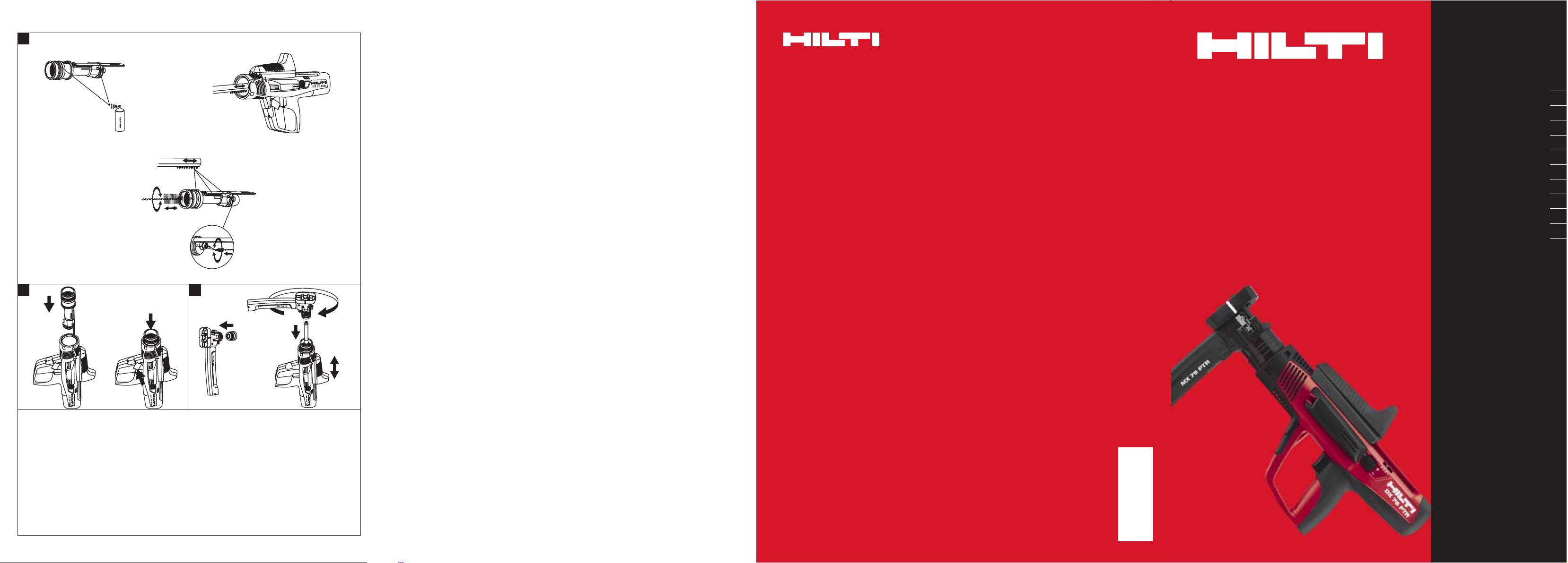
7.5 Changing the nail magazine (or fastener
guide)
7.5.1 Assembly
1. Insert the piston brake, the right way round, in
the piston guide (or fastener magazine) that is to
be fitted to the tool.
2. Insert the piston in the piston guide in the tool.
3. Screw the fastener guide (or fastener magazine)
onto the piston guide as far as it will go and then
turn it back until it engages.
4. Cycle the tool once with the cycling grip.
7.5.2 Disassembly
WARNING
All cartridges must be removed from the tool. The
fastener magazine must be empty.
CAUTION
After the tool has been in use, the parts to be handled
may be very hot. It is essential that gloves are worn
if the following maintenance operations have to be
carried out before the tool has been allowed to cool
down.
1. Check that the tool cycling grip is in its starting
position.
2. Unscrew and remove the fastener guide (or
fastener magazine).
3. Remove the piston brake from the fastener guide.
en
25
Page 12

8. Care and maintenance
CAUTION
en
When this type of tool is used under normal operating
conditions, dirt and residues build up inside the tool
and functionally relevant parts are also subject to
wear. Regular inspections and maintenance are
thus essential in order to ensure reliable operation.
We recommend that the piston and piston brake are
checked and inspected at least daily when the tool
is subjected to intensive use, and at the latest after
driving 3,000 fasteners.
WARNING
The tool must be unloaded before carrying out care
and maintenance.
CAUTION
The tool may get hot during use. You could burn your
hands. Wear protective gloves when carrying out
care and maintenance. Allow the tool to cool down.
8.1 Care of the tool
Clean the outside of the tool at regular intervals with
a slightly damp cloth.
NOTE
Do not use a spray or steam/water jet system for
cleaning! Never operate the tool when the ventilation
slots are blocked. Do not permit foreign objects to
enter the interior of the tool.
8.2 Maintenance
Check all external parts of the tool for damage at
regular intervals and check that all controls operate
faultlessly. Do not operate the tool if parts are damaged or when the controls do not function faultlessly.
If necessary, the tool should be repaired by Hilti
Service.
Use the tool only with the recommended cartridges
and power settings. Use of the wrong cartridges or
use of excessively high power settings may lead to
premature failure of parts of the tool.
CAUTION
Dirt and residues in DX tools contain substances that
may be hazardous to your health. Do not inhale dust
/ or dirt from cleaning. Keep the dust or dirt away
from foodstuffs. Wash your hands after cleaning
the tool. Never use grease for the maintenance/
lubrication of parts of the tool. This may lead to
malfunctions. Use only Hilti lubricant spray or a
product of equivalent quality.
8.2.1 Checking and replacing the piston and
piston brake
WARNING
All cartridges must be removed from the tool. The
fastener magazine must be empty.
CAUTION
After the tool has been in use, the parts to be handled
may be very hot. It is essential that gloves are worn
if the following maintenance operations have to be
carried out before the tool has been allowed to cool
down.
NOTE
Firing the tool repeatedly without driving a fastener
stresses the piston and piston brake and causes these
parts to wear. If the piston shows signs of chipping
and / or the synthetic rubber part of the piston brake
is badly worn, then these parts have reached the end
of their life.
NOTE
The condition of the piston and piston brake must be
checked at regular intervals and at least daily.
NOTE
To replace the piston and the piston brake it is
necessary only to unscrew the fastener magazine or
the fastener guide. It is not necessary to remove the
piston guide.
1. Unscrew and remove the fastener guide (or
fastener magazine).
2. Pull the piston out of the piston guide.
26
Page 13

3. Check the piston for damage. If signs of damage
are found, the piston AND the piston brake must
be replaced. Check the piston brake for signs of
wear of the synthetic rubber part.
NOTE Check the piston for straightness by rolling
it on a smooth surface. Never use worn or damaged pistons and do not attempt to manipulate or
modify the piston.
4. If the piston has to be replaced, remove the piston
brake from the fastener guide.
5. Insert the new piston brake, the right way round,
in the fastener guide (or fastener magazine) that
is to be fitted to the tool.
6. Insert the piston in the piston guide in the tool.
7. Screw the fastener guide (or fastener magazine)
onto the piston guide as far as it will go and then
turn it back until it engages.
8. Cycle the tool once with the cycling grip.
8.2.2 Cleaning the piston guide
WARNING
All cartridges must be removed from the tool. The
fastener magazine must be empty.
CAUTION
After the tool has been in use, the parts to be handled
may be very hot. It is essential that gloves are worn
if the following maintenance operations have to be
carried out before the tool has been allowed to cool
down.
1. Check that the tool cycling grip is in its starting
position.
2. Unscrew and remove the nail magazine (or the
fastener guide).
3. Remove the piston from the piston guide and
remove the piston brake from the nail magazine
(or fastener guide).
4. CAUTION It is essential that the tool is held
with thepiston guide facing upwards. The piston
guide may otherwise fall out.
Open the piston guide release lever.
5. Pull the piston guide out of the tool.
NOTE Further disassembly of the piston guide is
not necessary.
6. Use the large brushes to clean the inside and
outside surfaces of the piston guide.
7. Use the small round brush to clean the bore for
the regulating pin and use the tapered brush to
clean the cartridge chamber.
8. Clean the seat of the piston guide in the tool.
9. Lubricate the slider and the collar of the piston
guide with Hilti spray.
10. Lubricate the steel parts inside the tool with Hilti
spray.
NOTE Use of lubricants other than Hilti spray
may cause damage to rubber parts.
11. Insert the piston guide into the tool.
12. Apply light pressure to the piston guide.
NOTE The lever can be closed only when the
piston guide is pressed (several mm) into the tool.
If the lever still cannot be closed, please refer to
the information in section 9 “Troubleshooting”.
13. Close the piston release lever with light pressure
applied to the piston guide.
14. Insert the piston in the piston guide.
15. Fit the piston brake.
16. Screw the fastener guide (or fastener magazine)
onto the piston guide as far as it will go and then
turn it back until it engages.
17. Lubricate the cartridge transport mechanism by
spraying Hilti lubricant into the gap in the housing
behind the cycling grip.
18. Cycle the tool once with the cycling grip.
8.3 Checking the tool after care and
maintenance
After carrying out care and maintenance and before
loading the cartridges, check that all safety devices
have been fitted and that they function faultlessly.
en
27
Page 14

9. Troubleshooting
WARNING
The tool must be unloaded before taking any steps to remedy faults.
Fault Possible cause Remedy
en
Cartridges are not transported.
Cartridge strip can’t be removed.
Cartridge doesn't fire. The tool is not pressed fully against
Fastener penetrates too
deeply (inadequate fastener
stand‐off).
h
The cartridge strip is damaged.
The tool is damaged.
The tool is damaged or has
overheated as a result of an
excessively high fastener driving
rate.
the working surface.
The cartridge strip is used up. Remove the used cartridge strip.
The magazine or fastener guide is
not screwed on far enough.
One of the cartridges is faulty. Cycle the tool and use up the
The tool is defectiveor the cartridges
are faulty.
The tool is not cycled.
The fastener missed the steel beam. Mark the position of the beam. Drive
There is space between the sheet
and the supporting material.
The wrong piston has been fitted. Check that the right combination
Change the cartridge strip.
See section: 7.3.1 Removing
cartridges from the tool 7
Contact Hilti.
Allow the tool to cool and then
carefully try again to remove the
cartridge strip. Remove the piston
guide from the tool. If a cartridge
sleeve remains jammed in the
cartridge chamber, use the round
rod from the cleaning set to remove
it. If this is still not possible, contact
Hilti.
NOTE
Do not attempt to forcibly remove
cartridges from the magazine strip
or tool.
Press the tool fully against the
working surface and pull the trigger.
Load a new strip.
Screw the magazine farther onto the
tool.
remaining cartridges.
Contact Hilti.
Cycle the tool.
another fastener into the beam.
Check to ensure that the sheet
rests tightly against the supporting
material.
of piston and fastener is used.
Use the X‑76‑P‑ENP‑PTR piston
for X‑ENP fasteners. Use the
X‑76‑P‑ENP2K‑PTR piston for
ENP2K fasteners.
28
Page 15

Fault Possible cause Remedy
Fastener doesn’t penetrate
deeply enough (excessive
fastener stand‐off).
h
Fastener driven into the rib of the
beam.
Supporting material is too thick, or
the thickness has changed.
Drive a second fastener.
Increase fastener driving power in
accordance with recommendations
or, respectively, use a more
powerful cartridge.
See section: 7.2.2 Selecting the
cartridge 3
Fastener driving power is too low.
Increase fastener driving power in
accordance with recommendations
or, respectively, use a more
powerful cartridge.
See section: 7.2.2 Selecting the
cartridge 3
The tool needs to be cleaned.
The piston is broken.
The tool is damaged.
Clean the tool.
Change the piston and piston brake.
Contact Hilti.
The wrong piston has been fitted. Check that the right combination
of piston and fastener is used.
Use the X‑76‑P‑ENP‑PTR piston
for X‑ENP fasteners. Use the
X‑76‑P‑ENP2K‑PTR piston with
green mark for ENP2K fasteners.
Fastener stand‐off (head projection) varies considerably.
h
h
The tool was pressed against the
working surface with a jolt.
The tool is cycled unevenly,
sometimes not fully.
Irregular driving power.
Press the tool against the working
surface smoothly and avoid jolting.
Cycle the tool fully.
Clean the tool. Replace wearing
parts with new parts. Contact Hilti
if irregular driving power is still
experienced.
Shear breakage. The face of the piston is worn or
Change the piston and piston brake.
chipped.
Fastener driven into the rib of the
beam.
The tool is pressed against the
working surface at an angle.
Supporting material is too thick, or
the thickness has changed.
Drive a second fastener beside the
first one.
Press the tool against the working
surface at right angles.
Check that the recommended type
of fastener is used. If the right type
of fastener is used, increase driving
power in accordance with cartridge
recommendations or use a more
powerful cartridge.
The tool remains compressed
(doesn’t extendwhen pressure
is released).
The piston is sticking in the piston
brake.
Change the piston and piston brake.
See section: 7.5.2 Disassembly
See section: 7.5.1 Assembly
en
29
Page 16

Fault Possible cause Remedy
The tool remains compressed
(doesn’t extendwhen pressure
is released).
The tool needs to be cleaned.
The cartridge strip has jammed, the
tool has overheated.
en
The tool can’t be fired.
No fastener is driven.
The fastener guide can’t be
screwed on to the tool fully.
The piston can’t be fitted.
The tool wasn’t cycled correctly, the
cycling grip is not in the starting
position.
The trigger is pulled before the tool
is pressed fully against the working
surface.
Fastener transport malfunctions See section: 7.2.1 Loading fastener
The magazine or fastener guide is
not screwed on far enough.
The tool is damaged.
The tool wasn’t cycled correctly, the
cycling grip is not in the starting
position.
No fasteners in the tool. Load fastener(s) into the tool.
The magazine fastener transport
mechanism is faulty.
No piston in the tool. Fit the piston.
The piston is broken.
The piston doesn’t return to its
starting position.
The fastener guide needs to be
cleaned.
Fasteners are jammed inthe fastener
guide.
The piston guide needs to be
cleaned at the end of the threaded
section.
The tool, especially the piston guide,
needs to be cleaned.
Pins are visible in the piston guide.
See section: 8.2.2 Cleaning the
piston guide
Please refer to the fault: “Cartridge
strip can’t be removed”. Do not
exceed the maximum recommended
fastener driving rate.
Cycle the tool completely and return
the cycling grip to the starting
position.
Press the tool fully against the
working surface and then pull the
trigger.
strips in the magazine 2
See section: 7.3.2 Removing
fastener strips from the tool 8
Screw the magazine farther onto the
tool.
Contact Hilti.
Cycle the tool completely and return
the cycling grip to the starting
position.
Contact Hilti.
Change the piston and piston brake.
Contact Hilti.
Use the brushes provided to clean
the fastener guide and associated
parts. Lubricate with Hilti spray.
Remove the jammed fasteners.
Remove magazine strip plastic
scraps from the tool magazine.
Avoid shear breakage (see above).
Avoid missing the beam (driving
the fastener into unsupported sheet
metal); mark the position of the
beams accurately if necessary.
Clean and lubricate the thread.
Clean the fastener guide and the
tool and refit the piston.
Pull the pins forward until they can
engage.
30
Page 17

Fault Possible cause Remedy
The piston guide can’t be
fitted.
Stiff cycling action.
The lever is in the closed position.
The piston guide is incorrectly
positioned.
The tool needs to be cleaned.
The piston and piston brake have
almost reached the end of their
service life.
The tool is damaged.
See section: 8.2.2 Cleaning the
piston guide
See section: 8.2.2 Cleaning the
piston guide
Clean the tool.
See section: 8.2.2 Cleaning the
piston guide
Change the piston and piston brake.
Contact Hilti.
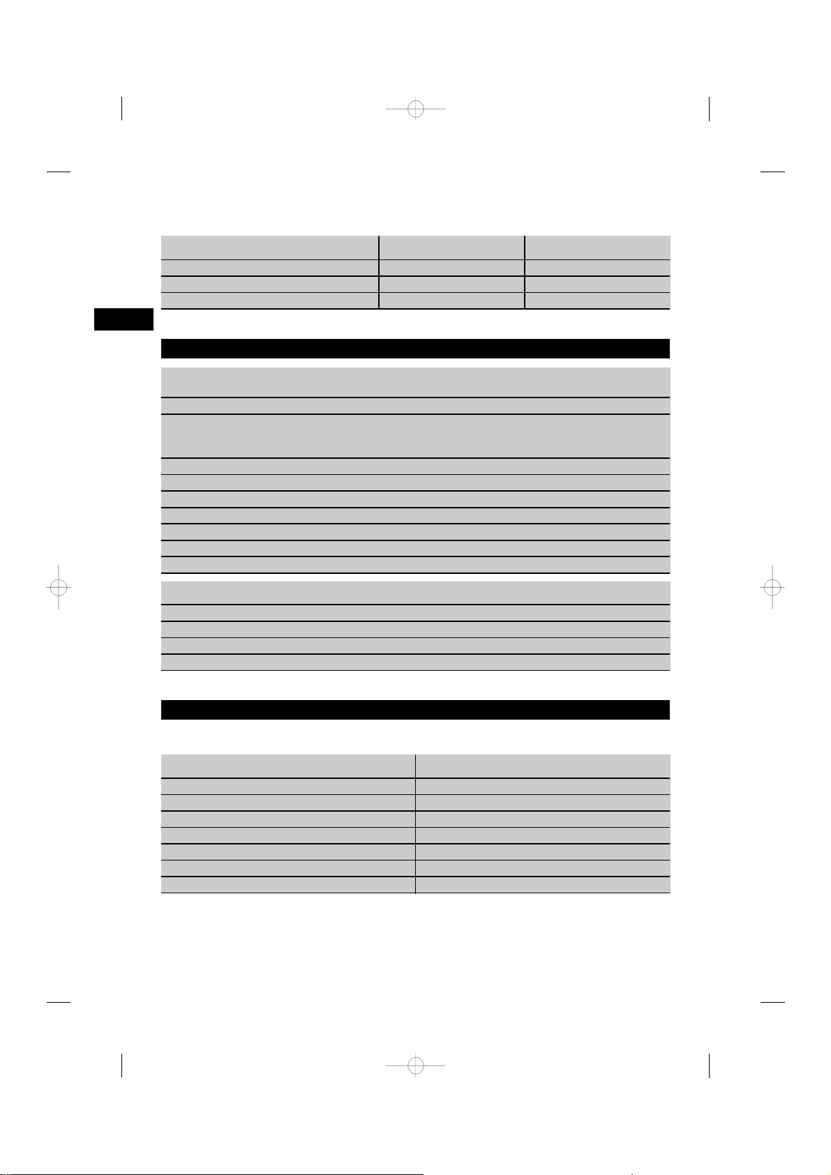
10. Disposal
Most of the materials from which Hilti tools or appliances are manufactured can be recycled. The materials must
be correctly separated before they can be recycled. In many countries, Hilti has already made arrangements
for taking back old tools and appliances for recycling. Ask Hilti customer service or your Hilti representative for
further information. If you wish to bring the tool to a recycling facility yourself: Follow regional and international
directives and regulations.
Separate the individual parts as follows:
Part / assembly Main material Recycling
Hilti toolbox Plastic Plastics recycling
Outer casing Plastic/Synthetic rubber
Piston
Piston brake
Screws, small parts Steel Scrap metal
Used/partly‐used cartridge strips
Steel Scrap metal
Steel/Plastic Scrap metal
Steel/Plastic
Plastics recycling
In accordance with local regulations
en
11. Manufacturer’s warranty ‐ tools
Hilti warrants that the tool supplied is free of defects
in material and workmanship. This warranty is valid
so long as the tool is operated and handled correctly,
cleaned and serviced properly and in accordance with
the Hilti Operating Instructions, and the technical
system is maintained. This means that only original
Hilti consumables, components and spare parts, or
other products of equivalent quality, may be used in
the tool.
This warranty provides the free‐of‐charge repair or
replacement of defective parts only over the entire
lifespan of the tool. Parts requiring repair or replacement as a result of normal wear and tear are not
covered by this warranty.
Additional claims are excluded, unless stringent national rules prohibit such exclusion. In particular,
Hilti is not obligated for direct, indirect, incidental
31
Page 18

or consequential damages, losses or expenses in
connection with, or by reason of, the use of, or
inability to use the tool for any purpose. Implied
warranties of merchantability or fitness for a particular purpose are specifically excluded.
en
12. Confirmation of CIP testing
The Hilti DX 76 PTR has been system and type
tested. As a result, the tool bears the rectangular PTB
approval mark showing approval number S 816. Hilti
thus guarantees compliance with the approved type.
For repair or replacement, send the tool or related
parts immediately upon discovery of the defect to
the address of the local Hilti marketing organization
provided.
This constitutes Hilti’s entire obligation with regard
to warranty and supersedes all prior or contemporaneous comments and oral or written agreements
concerning warranties.
Unacceptable defects or deficiencies, etc. determined
during use of the tool must be reported to the person
responsible at the approval authority (PTB) and to the
Office of the Permanent International Commission
(C.I.P.).
32
 Loading...