

Page 1
DX76
*282470*
282470
Bedienungsanleitung de
Operating instructions en
Ръководство за обслужване
bg
Upute za uporabu hr
Instrukcja obsługi pl
Инструкция по зксплуатации
ru
Návod na obsluhu sk
Navodila za uporabo sl
Návod k obsluze cs
Használati utasítás hu
Page 2
1
16
2
15
1
17
3 4 5 6 7
18
MX 76
14 13
12 11 10
8
9
1
2
3
4
X 76
D
21
22
19
20
1
2
3
4
76
X
D
Page 3
DX 76
MX 76
DX 76
MX 76
MX 76MX 76
1234
DX 76DX 76
1
2
3
DX 76
MX 76
DX 76
MX 76
DX 76
MX 76
MX 76
MX 76
MX 76
2 3
4 5
6 7
8 9
1
1234
DX 76
1
1234
DX 76
MX 76
D
X
7
6
1
2
M
X
7
6
MX 76
1
2
3
4
3
6
7
X
M
max.
min.
max.
1/4
min.
1
6
7
X
M
DX 76
3
2
1
2
3
4
DX 76
2
6
7
X
M
3
6
7
X
M
4
1
1
2
3
4
MX 76
2
1
6
7
X
D
M
X
7
6
2
MX 76
4
4
3
2
1
D
X
7
6
5
Page 4
DX 76
DX 76
10
11 12
13 14
X-ENP
2
1
Standard
steel
High-strength
steel
20
4
4
15
red
3
10
Base material thickness (mm)
8
6
4
3
S 235, S275
E 36, ST 37,
340-470 N/mm
blue
2
3
4
3
S 355, S275
E 42, ST 52,
490-630 N/mm
3
1
black
red
2
2
1
4
DX 76
1234
3
2
3
1
DX 76
2
5
6
4
Page 5
DX 76
DX 76
DX 76
MX 76
15 16
17
19
20 21
h
h
h
h
DX 76
MX 76
18
a)
c)
b)
d)
2
5
1
3
4
3
4
1
2
h
max.
min.
max.
min.
M
X
7
6
4
1
3
5
1
2
6
3
4
7
X
D
2
7
4
3
2
1
D
4
3
2
1
D
X
7
6
X
7
6
9
1
2
3
X 76
4
D
8
5
10
6
M
X
7
6
12
11
14
4
3
2
1
D
X
7
6
4
3
2
1
DX 76
13
Page 6
17
en
It is essential that the operating instructions
are read before the tool is operated for the
first time.
Always keep these operating instructions
together with the tool.
Ensure that the operating instructions are
with the tool when it is given to other
persons.
DX 76 powder -actuated fastening tool
1. General information
1.1 Safety notices and their meaning
-WARNING-
Draws attention to a potentially dangerous situation that
could lead to severe personal injury or death.
-CAUTION-
Draws attention to a potentially dangerous situation that
could lead to minor personal injury or damage to the
equipment or other property.
-NOTE-
Indicates instructions and other useful information. Not
used to indicate potentially dangerous situations or situations where damage may occur.
1.2 Pictograms
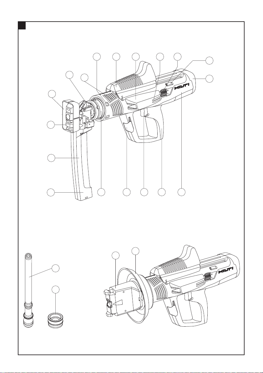
Parts of the tool
DX 76 MX tool
MX 76 fastener magazine
Contact pin
Protective cap
Cycling grip
Cartridge strip guideway
Loading status control window
Power regulation wheel
Power regulation indicator
Padded end cap
Tool casing
Grip pad
Trigger
Piston guide release lever
Sliding sleeve
Magazine casing
Fastener magazine spall guard
Fastener stop piece
Cooling slots
Warning signs
Obligation signs
Wear ear
protection
Wear
protective
gloves
Wear eye
protection
Read the
operating
instructions
before use.
Symbols
General
warning
Warning: explosive
substance
Warning:
hot surface
Wear a
hard hat
Contents Page
1. General information 17
2. Description 18
3. Fasteners, consumables and accessories 18
4. Technical data 20
5. Safety precautions 21
6. Before use 23
7. Operation 23
8. Care and maintenance 27
9. Troubleshooting 28
10. Disposal 30
11. Warranty 31
DX 76 F15 tool
X-76-F-15 fastener guide
Spall guard
Wearing parts
T
Piston
Z
Piston stopper
The numbers refer to the illustrations. The illustrations can be found on the fold-out cover pages. Keep
these pages open while you read the operating instructions.
In these operating instructions, the designation “the
tool” always refers to the DX 76 powder-actuated fastening tool.
Page 7

18
en
2. Description
2.1 Piston principle
The energy from the propellant charge is transferred to
a piston, the accelerated mass of which drives the fastener into the base material. Due to use of this piston
principle, the tool is classified as a “low velocity tool”.
Approximately 95% of kinetic energy is taken up by the
piston when the tool is fired. As the piston is always
stopped as it reaches the end of its travel, excess energy
is absorbed by the tool. Accordingly, when the tool is
used correctly, dangerous through-shots with a fastener
exit velocity in excess of 100 m/sec therefore become
virtually impossible.
2.2 Drop-firing safety device
The drop-firing safety device is the result of coupling
the firing mechanism with the cocking movement. This
prevents the tool from firing when dropped onto a hard
surface, no matter at which angle the impact occurs.
2.3 Trigger safety device
The trigger safety device ensures that a fastener cannot
be driven simply by pulling the trigger only. The tool
must be pressed against a firm surface before a fastener
can be released.
2.3.1 Contact pressure safety device
The tool can be fired only when pressed fully against a
firm surface with a force of at least 50 N.
2.3.2 Unintentional firing safety device
The tool is also equipped with an unintentional firing
safety device. This prevents the tool from firing if the
trigger is first pulled and the tool then pressed against
the work surface. The tool can be fired only when it is
first pressed correctly against the work surface and the
trigger subsequently pulled.
Location of identification data on the tool
The type designation and serial number are printed on
the type plate on the tool. Make a note of this information in your operating instructions and always refer to
it when making an enquiry to your Hilti representative
or service department.
Type:
Serial no.:
3. Fasteners, consumables and accessories
3.1 DX 76 MX tool: applications and suitable fasteners
Application: fastening profile metal sheet to steel, steel thickness 6 mm – solid steel
Fastener
Magazine
Piston
Application: fastening profile metal sheet to steel, steel thickness 3–8 mm
Fastener
Magazine
Piston
Ordering designation
X-ENP-19 L15 MX
MX 76
X-76-P-ENP
Comments
10 fasteners per magazine strip
Ordering designation
ENP2K-20 L15 MX
MX 76
X-76-P-ENP2K
Comments
10 fasteners per magazine strip
Page 8

19
en
3.2 DX 76 F15 tool with accessories: applications and suitable fasteners
Application: fastening profile metal sheet to steel, steel thickness 6 mm – solid steel
Fastener
Fastener guide
Fastener guide
Piston
Application: fastening profile metal sheet to steel, steel thickness 3–8 mm
Fastener
Fastener guide
Fastener guide
Piston
Ordering designation
X-ENP-19 L15
X-76-F-15
X-76-F-N15
X-76-P-ENP
Comments
Single fasteners
Narrow fastener guide only for USA
Ordering designation
ENP2K-20 L15
X-76-F-15
X-76-F-N15
X-76-P-ENP2K
Comments
Single fasteners
Narrow fastener guide only for USA
Application: fastening shear connectors
Fastener
Shear connector
Fastener guide
Piston
Ordering designation
X-ENP-21 HVB
X-HVB 50 / 80 / 95 / 110 /
125 / 140
X-76-F-HVB
X-76-P-HVB
Comments
2 fasteners per shear connector
Application: fastening profile metal sheets to concrete (DX-Kwik)
Fastener
Magazine
Piston
Stepped drill bit
Ordering designation
NPH2-42L15
X-76-F-Kwik
X-76-P-Kwik
TX-C 5/23
Comments
Stepped drill bit for predrilling
Application: 10 mm diameter studs for fastening gratings
Fastener
Fastener guide
Piston
Ordering designation
EM8-15 FP10,
X-CRM8-15 FP10
X-76-F-10
X-76-P-GR
Ramrod
25
30
Comments
For fastening with the X-FCM, X-FCM-F , X-FCM-R,
X-FCP-F , X-FCP-R
Ramrod for pushing the fastener into the tool
Centering device for the X-76-F-10 fastener guide
Centering device for the X-76-F-10 fastener guide
Application: 10 mm diameter fasteners for various applications on steel and concrete
Fasteners
Fasteners
Fasteners
Fastener guide
Piston
Ordering designation
DS 27-117
DSH 57 P10
EDS 19-27 P10
EW10-30 P10,
X-EW10-27 P10,
X-EM10-24 P10
X-76-F-10
X-76-P-10
Comments
Nail for fastening wood battens to concrete and
steel. Nail must be predriven for thicknesses of
62mm and greater.
Nail for fastening wood battens to steel
10 mm threaded studs for use on steel
Page 9

20
en
Ordering designation
6.8/18 M black (purple)
6.8/18 M red
6.8/18 M blue
6.8/18 M yellow
6.8/18 M green
3.3 Cartridges
Comments
Extra heavy (USA)
Very heavy
Heavy
Medium
Light
3.4 Other wearing parts
Ordering designation
X-76-PS
Comments
Piston stopper
Ordering designation
DX 76/860-ENP cleaning set
I-VO 805 PS
I-VO 808 PS
Ear protectors
DX 76 MX
DX 76 KD
Hilti spray
3.5 Other accessories
Comments
Flat brush, round brush 25 mm dia., round brush 8 mm dia.,
pusher, cleaning cloth
Protective glasses, clear
Protective glasses, tinted
Small
Toolbox for magazine tool
Toolbox, large, with lockable cartridge compartment
4. T echnical data
Tool
Weight
Dimensions (L×W×H)
Magazine capacity
Contact movement
Contact pressure
Ambient operating temperature range
Maxim fastener driving rate*
*
for trouble-free operation
Right of technical changes reserved.
DX 76 MX DX 76 F15
4.35 kg 3.83 kg
450 mm
×
101 mm×352 mm 452 mm×104 mm×238 mm
10 fasteners
32 mm
190–240 N
–15 ˚C to 50 ˚C
600 per hour
Page 10

21
en
5. Safety precautions
5.1 Basic safety instructions
In addition to the safety precautions listed in the individual sections of these operating instructions, the following points must be strictly observed at all times.
5.2 Use of the tool as directed
The tool is intended for use in the construction industry and associated trades for driving fasteners of various types (nails, threaded studs and composite fasteners), mainly into steel but also into concrete.
5.3 Misuse of the tool
● Manipulation or modification of the tool is not per-
missible.
● Use of the tool in an explosive or inflammable atmos-
phere is not permissible.
● To avoid the risk of injury, use only genuine Hilti fas-
teners, cartridges, accessories and spare parts or
those of equivalent quality.
● Observe the information printed in the operating instruc-
tions concerning operation, care and maintenance.
● Never point the tool at yourself or at any bystander.
● Never press the nosepiece of the tool against your
hand or other part of your body (or other person's
hand or parts of their body).
● Never attempt to drive fasteners into materials such
as glass, marble, plastic, bronze, brass, copper, rock,
insulation material, hollow brick, ceramic brick, thin
sheet metal (< 3 mm) cast iron or cellular concrete.
● The tool and its ancillary equipment may present haz-
ards when used incorrectly by untrained personnel or
not as directed.
● Pull the trigger only when the nosepiece of the tool is
in contact with the base material.
● Never attempt to redrive a fastener. This may cause
the fastener to break or shatter.
● Never attempt to drive a fastener in an existing hole
except where this is recommended by Hilti (e.g. DXKwik applications).
● Always observe the application guidelines.
5.4 State-of-the-art technology
● The tool is designed and built using state-of-the-art
technology.
● The tool and its ancillary equipment may present haz-
ards when used incorrectly by untrained personnel or
not as directed.
5.5 T ake the necessary precautions at the
workplace
● Ensure that the working area is well lit.
● The tool is for hand-held use only.
● Keep other persons, children in particular, away from
the working area.
● Before driving fasteners, check that no one is present
immediately behind or below the work surface.
● Keep the workplace tidy. Objects which could cause
injury should be removed from the working area.
Untidiness at the workplace can lead to accidents.
● Keep the grips of the tool clean, dry and free form oil
and grease.
5.6 General safety precautions
● Use the right tool for the job. Do not use the tool for
purposes for which it was not intended. Use the tool
only as directed and when it is in faultless condition.
● Use the spall guard when the application permits.
● Press the tool against the work surface at right angles.
● Never leave a loaded tool unattended.
● Always remove all cartridges and fasteners from the
tool before carrying out cleaning, servicing or maintenance and before storing the tool.
● Never pull the magazine back with the hand. Under
certain circumstances, this could cock the tool, making it ready to fire. When the tool is ready to fire, a fastener could be driven inadvertently into a part of the
body.
● When not in use, the tool must be unloaded and stored
in a dry place where it is locked up or out of reach of
children.
● Check that moving parts function correctly without
sticking and that no parts are damaged. All parts must
be fitted correctly and fulfill all conditions necessary
for correct operation of the tool.
● Check the tool for possible damage. Protective devices
and any parts that may have suffered slight damage
should be checked for correct operation and functionality before further use. Damaged safety devices
or other damaged parts must be replaced or repaired
properly by an authorized repair workshop unless otherwise indicated in the operating instructions.
● Always hold the tool securely and at right angles to
the working surface. This will reduce the risk of the
fastener being deflected by the working surface.
Page 11

22
en
● Take the influences of the surrounding area into account.
Do not use the tool where there is a risk of fire or explosion.
● Keep the grips clean, dry and free from oil and grease.
5.6.1 Mechanical hazards
● Select the correct fastener guide, piston and fastener
combination for the job on hand. Failure to use the
correct combination of these items may result in damage to the tool and/or unsatisfactory fastening quality.
● Never use worn or damaged pistons and do not attempt
to manipulate or modify the piston.
● Use only fasteners of a type approved for use with the
tool.
5.6.2 Thermal hazards
● Allow the tool to cool down. Always wear gloves if the
tool has to be dismantled for cleaning or maintenance
before it has been allowed to cool down.
● Do not exceed the recommended fastener driving rate.
The tool may otherwise overheat.
● The tool must be allowed to cool down if melting of
the plastic cartridge strip is observed.
5.6.3 Danger of explosion
● Use only cartridges of a type approved for use with
the tool.
● Remove the cartridge strip from the tool carefully.
● If a cartridge fails to fire or misfires, always proceed
as follows:
1. Keep the tool pressed at right angles against the
working surface for 30 seconds.
2. If the cartridge still fails to fire, lift the tool away
from the working surface, taking care to avoid
pointing it at yourself or other persons.
3. Load the next cartridge on the strip by cycling the
tool. Use up the remaining cartridges on the strip
and remove the used cartridge strip from the tool.
The (partly) used cartridge strip must then be disposed of suitably in order to prevent further use
or misuse of any unfired cartridges.
● Do not attempt to forcibly remove cartridges from the
magazine strip or tool.
● Unused cartridges must be stored in a dry, high place,
locked up or out of reach of children.
5.7 Requirements to be met by users
● The tool is intended for professional use.
● The tool may be operated, serviced and repaired only
by authorized, trained personnel. This personnel must
be informed of any special hazards that may be encountered.
● Always concentrate on your work. Proceed carefully
and do not use the tool if your full attention is not on
the job.
● Wear non-slip shoes when working outdoors.
● Avoid unfavorable body positions. Work from a secure
stance and stay in balance at all times.
● Keep the arms flexed while using the tool (do not
straighten the arms).
5.8 Personal protective equipment
● The operator and other persons in the immediate vicin-
ity must always wear eye protection, a hard hat, ear
protectors and protective gloves while the tool is in
use or when checking the tool in case of a fault.
Page 12

DX 76
MX 76
23
en
6. Before use
6.1 Check the tool
● Check that no cartridge strip is loaded in the tool. If a
cartridge strip is present in the tool, use the cycling
grip to cycle the tool several times until the cartridge
strip projects from the tool at the cartridge strip exit
and can be pulled from the tool.
● Check all external parts of the tool for damage at reg-
ular intervals and check that all controls operate properly. Do not operate the tool when parts are damaged
or when the controls do not operate properly. If necessary, have the tool repaired at a Hilti service centre.
● Check the piston stopper and piston for wear and
ensure that the parts have been fitted correctly.
7.1 Using the tool
-NOTEFastening instructions
These instructions must be observed at all times.
For detailed information, please ask your local Hilti representative for a copy of the applicable technical guidelines or national technical regulations.
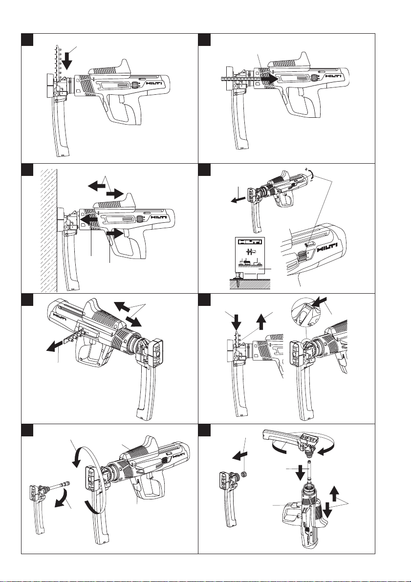
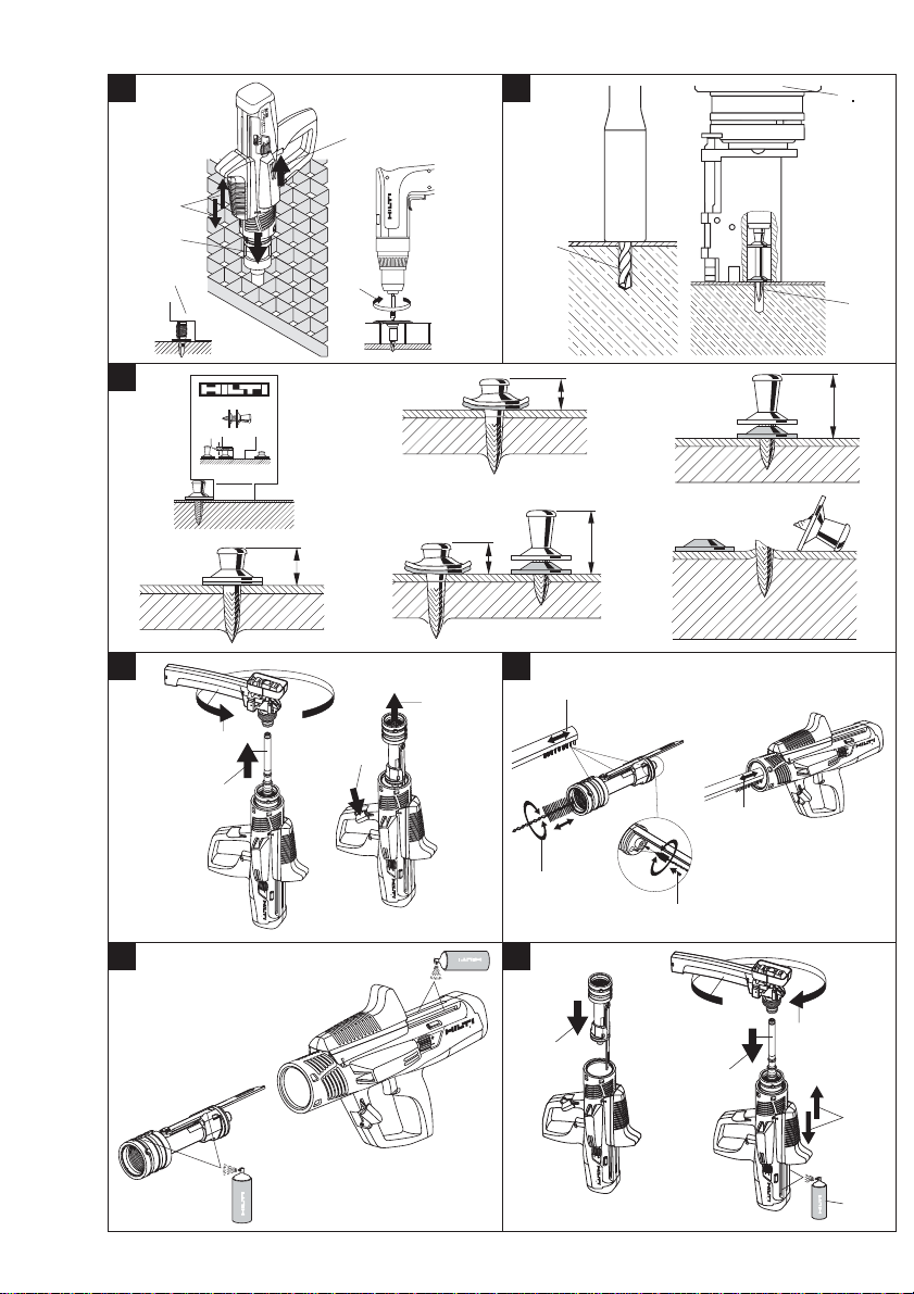
7.2 Driving fasteners with the magazine tool
7.2.1 Loading a fastener strip in the magazine
1.Push the fastener strip into the magazine from above
until the washers on the last fastener engage in the
magazine.
7.2.2 Selecting the cartridge
1.Determine the thickness of the material to be fastened
and the grade of the supporting steel.
2.Select a suitable cartridge and power setting for standard or high-strength steel (in accordance with the
cartridge recommendations).
7.2.3 Inserting the cartridge strip
1.Push the cartridge strip into the cartridge strip guideway on the side of the tool as far as it will go.
7.2.4 Driving fasteners with the magazine tool
1.Press the tool against the working surface at right
angles.
2.Drive the fastener by pulling the trigger.
3.Prepare the tool for driving the next fastener by pushing the cycling grip back toward the rear of the tool
and then forward to its original position.
-WARNING-
Do not attempt to drive fasteners in existing holes unless
this is recommended by Hilti for a particular application
(e.g. DX-Kwik). Do not attempt to redrive a fastener.
Do not exceed the recommended maximum fastener
driving rate.
7. Operation
-WARNING-
● Driving a fastener may cause flying
fragments.
● Flying fragments may injure parts
of the body or the eyes.
● The operator and bystanders must
wear protective glasses and a hard
hat.
-WARNING-
● The fastener is driven by the energy
relesed when a cartridge is fired.
● An excessively high noise level may
damage the hearing.
● The operator and bystanders must
wear ear protectors.
-WARNING-
● Making the tool ready to fire
by pressing it against a part
of the body (e.g. the hand)
is not permissible.
● This could cause a fastener
to be driven into a part of
the body.
● Never press the tool against
a part of the body.
1234
DX 76
6
7
X
M
Page 13

24
en
7.2.5 Checking and adjusting fastener driving
depth
Fastener driving depth can be adjusted by turning the
power regulation wheel on the tool.
Setting 1 = minimum
Setting 4 = maximum
1.Check the fastener stand-off.
2.If a fastener is not driven deeply enough, driving power
must be increased. Adjust the power regulation wheel
to the next higher setting. If a fastener is driven too
deeply, driving power must be decreased. Adjust the
power regulation wheel to the next lower setting.
3.Drive a fastener.
4.Check the stand-off.
5.If the fastener is still not driven deeply enough or,
respectively, is driven too deeply, steps 2 to 4 must
be repeated until the correct depth is achieved. If necessary, use a cartridge with a higher or lower power
rating.
7.3 Unloading the tool
7.3.1 Removing cartridges from the tool
-WARNING-
Do not attempt to forcibly remove cartridges from the
magazine strip or tool.
1.Advance the cartridge strip through the tool by moving the cycling grip until the strip is visible at the exit
aperture.
2.Pull the cartridge strip out of the tool at the cartridge
strip exit aperture.
7.3.2 Removing fastener strips from the tool
-WARNING-
Check that no cartridge strip is present in the tool. If
there is a cartridge strip in the tool, pull it out of the tool
by hand through the exit aperture.
1.Push the fastener strip 5 mm further into the magazine and hold it securely in this position.
2.Push the catch forward with the thumb and hold it in
this position.
3.Remove the fastener strip from the magazine (-CAU-
TION- the fastener strip is ejected under spring pressure).
7.4 Changing the fastener guide (or fastener
magazine)
7.4.1 Disassembly
-WARNING-
All cartridges must be removed from the tool.
The fastener magazine must be empty.
-CAUTION-
After the tool has been in use, the parts to be handled
may be very hot. It is essential that gloves are worn if
the following maintenance operations have to be carried out before the tool has been allowed to cool down.
1.Check that the tool cycling grip is in its starting position.
2.Pull out the piston guide release lever.
3.Unscrew and remove the fastener guide (or fastener
magazine).
4.Remove the piston stopper from the fastener guide
(using the piston as an aid, if necessary).
7.4.2 Assembly
1.Insert the piston stopper the right way round (rubber
toward the front) in the piston guide (or fastener magazine) that is to be fitted to the tool.
2.Insert the piston in the piston guide in the tool.
3.Screw the fastener guide (or fastener magazine) onto
the piston guide as far as it will go and then turn it
back until it engages.
4.Close the piston guide release lever.
5.Cycle the tool once with the cycling grip.
7.5 Driving fasteners with the single-fastener tool
(accessories required)
7.5.1 Inserting the fastener in the single-fastener
tool
1.Turn the tool so that the fastener guide is pointing
upwards.
2.Insert the fastener in the tool from above.
7.5.2 Selecting the cartridge
1.Determine the thickness of the material to be fastened
and the grade of the supporting steel.
2.Select a suitable cartridge and power setting for standard or high-strength steel (in accordance with the
cartridge recommendations).
7.5.3 Inserting the cartridge strip
1.Push the cartridge strip, as far as it will go, into the
cartridge strip guideway on the side of the tool.
Page 14

25
en
7.5.4 Driving fasteners with the single-fastener
tool
1.Press the tool against the working surface at right
angles.
2.Drive the fastener by pulling the trigger.
3.Prepare the tool for driving the next fastener by pushing the cycling grip back toward the rear of the tool
and then forward to its original position.
-WARNING-
Do not attempt to drive fasteners in existing holes unless
this is recommended by Hilti for a particular application
(e.g. DX-Kwik). Do not attempt to redrive a fastener.
Do not exceed the recommended maximum fastener
driving rate.
7.5.5 Checking and adjusting fastener driving
depth
Fastener driving depth can be adjusted by turning the
power regulation wheel on the tool.
Setting 1 = minimum
Setting 4 = maximum
1.Check the fastener stand-off.
2.If a fastener is not driven deeply enough, driving power
must be increased. Adjust the power regulation wheel
to the next higher setting. If a fastener is driven too
deeply, driving power must be decreased. Adjust the
power regulation wheel to the next lower setting.
3.Drive a fastener.
4.Check the stand-off.
5.If the fastener is still not driven deeply enough or,
respectively, is driven too deeply, steps 2 to 4 must
be repeated until the correct depth is achieved. If necessary, use a cartridge with a higher or lower power
rating.
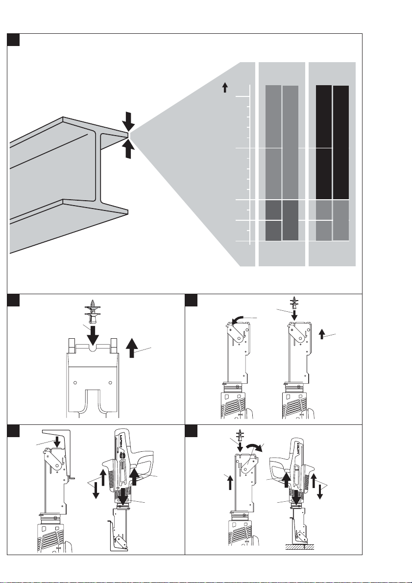
7.6 Fastening shear connectors (accessories
required)
-NOTEDriving the first fastener in the shear connector
7.6.1 Inserting the fastener in the single-fastener
tool
1.Move the slider until it engages and the number 1 is
visible.
2.Turn the tool so that the fastener guide is pointing
upwards.
3.Insert the fastener in the tool from above.
7.6.2 Inserting the cartridge strip
1.Push the cartridge strip, as far as it will go, into the
cartridge strip guideway on the side of the tool.
7.6.3 Driving the fastener
1.Place the shear connector on the tool nosepiece (it
will be held in place by a magnet).
2.Press the tool at right angles against the working surface.
3.Drive the fastener by pulling the trigger.
4.Prepare the tool for driving the next fastener by pushing the cycling grip back toward the rear of the tool
and then forward to its original position.
-WARNING-
Do not attempt to drive fasteners in existing holes unless
this is recommended by Hilti for a particular application
(e.g. DX-Kwik). Do not attempt to redrive a fastener.
Do not exceed the recommended maximum fastener
driving rate.
7.6.4 Power regulation
Adjust the power setting by turning the power regulation wheel on the tool.
Setting 1 = minimum
Setting 4 = maximum
1.Check the fastener stand-off.
2.If a fastener is not driven deeply enough, driving power
must be increased. Adjust the power regulation wheel
to the next higher setting. If a fastener is driven too
deeply, driving power must be decreased. Adjust the
power regulation wheel to the next lower setting.
3.Drive a fastener.
4.Check the stand-off.
5.If the fastener is still not driven deeply enough or,
respectively, is driven too deeply, steps 2 to 4 must
be repeated until the correct depth is achieved. If necessary, use a cartridge with a higher or lower power
rating.
-NOTE-
Driving the second fastener in the shear connector
7.6.5 Inserting the fastener in the single-fastener
tool
1.Move the slider until it engages and the number 2 is
visible.
2.Turn the tool so that the fastener guide is pointing
upwards.
3.Insert the fastener in the tool from above.
7.6.6 Driving the fastener
4.Guide the tool nosepiece into the shear connector and
press the tool against the working surface at right
angles.
5.Drive the second fastener by pulling the trigger.
6.Prepare the tool for driving the next fastener by pushing the cycling grip back toward the rear of the tool
and then forward to its original position.
Page 15

26
en
7.7 Fastening gratings (accessories required)
7.7.1 Inserting the fastener in the single-fastener
tool
1.Turn the tool so that the fastener guide is pointing
upwards.
2.Insert the fastener in the tool from above.
7.7.2 Inserting the cartridge strip
1.Push the cartridge strip into the cartridge strip guideway on the side of the tool as far as it will go.
7.7.3 Driving the fastener with the single-fastening
tool
1.Press the tool at right angles against the working surface.
2.Drive the fastener by pulling the trigger.
3.Check the depth of penetration by using the gauge to
measure fastener stand-off.
4.Screw on the retaining flange (torque = 5 to 8 Nm).
5.Prepare the tool for driving the next fastener by pushing the cycling grip back toward the rear of the tool
and then forward to its original position.
-WARNING-
Do not attempt to drive fasteners in existing holes unless
this is recommended by Hilti for a particular application
(e.g. DX-Kwik). Do not attempt to redrive a fastener.
Do not exceed the recommended maximum fastener
driving rate.
7.7.4 Power regulation
Adjust the power setting by turning the power regulation wheel on the tool.
Setting 1 = minimum
Setting 4 = maximum
1.Check the fastener stand-off.
2.If a fastener is not driven deeply enough, driving power
must be increased. Adjust the power regulation wheel
to the next higher setting. If a fastener is driven too
deeply, driving power must be decreased. Adjust the
power regulation wheel to the next lower setting.
3.Drive a fastener.
4.Check the stand-off.
5.If the fastener is still not driven deeply enough or,
respectively, is driven too deeply, steps 2 to 4 must
be repeated until the correct depth is achieved. If necessary, use a cartridge with a higher or lower power
rating.
7.8 Fastening profile metal sheets to concrete
(accessories required)
7.8.1 Inserting the fastener in the single-fastener
tool
1.Turn the tool so that the fastener guide is pointing
upwards.
2.Insert the fastener in the tool from above.
7.8.2 Inserting the cartridge strip
1.Push the cartridge strip, as far as it will go, into the
cartridge strip guideway on the side of the tool.
7.8.3 Driving the fastener with the single-fastener
tool
1.Use the stepped drill bit to predrill a hole through the
profile metal sheet and into the concrete.
2.Guide the tip of the fastener (projects from the fastener guide) into the hole drilled and press the tool
against the working surface at right angles.
3.Drive the fastener by pulling the trigger.
4.Prepare the tool for driving the next fastener by pushing the cycling grip back toward the rear of the tool
and then forward to its original position.
-WARNING-
Do not attempt to redrive a fastener.
Do not exceed the recommended maximum fastener
driving rate.
7.8.4 Power regulation
Adjust fastener driving power by turning the power regulation wheel on the tool.
Setting 1 = minimum
Setting 4 = maximum
1.Check the fastener stand-off.
2.If a fastener is not driven deeply enough, driving power
must be increased. Adjust the power regulation wheel
to the next higher setting. If a fastener is driven too
deeply, driving power must be decreased. Adjust the
power regulation wheel to the next lower setting.
3.Drive a fastener.
4.Check the stand-off.
5.If the fastener is still not driven deeply enough or,
respectively, is driven too deeply, steps 2 to 4 must
be repeated until the correct depth is achieved. If necessary, use a cartridge with a higher or lower power
rating.
Page 16

27
en
8. Care and maintenance
When this type of tool is used under normal operating
conditions, dirt and residues build up inside the tool and
functionally relevant parts are subject to wear. Regular
inspections and maintenance are thus essential in order
to ensure reliable operation:
Recommended interval for cleaning the tool and checking the condition of the piston and piston stopper:
● At least daily when the tool is subjected to intensive
use
● After 3,000 fasteners have been driven, at the lat-
est
-WARNING-
The tool must be unloaded before carrying out care and
maintenance.
8.2.1 Checking and replacing the piston and piston
stopper
-NOTE-
– If the tool is used incorrectly (e.g. no fastener loaded
in the tool before firing or the fastener is driven into
unsupported sheet metal), the piston may become
jammed against the piston stopper. Should the piston and piston stopper become fully seized in this
way, these parts have reached the end of their life.
The tool cannot be cycled when in this status.
– The condition of the piston and piston stopper must
be checked at regular intervals and at least daily.
-WARNING-
Check that there are no cartridges in the tool.
Check that there are no fasteners in the tool or magazine.
-CAUTION-
Parts of the tool may become very hot after a period of
use. Protective gloves must be worn if the following
maintenance procedure is carried out before the tool
has been allowed to cool down.
1. Unscrew and remove the fastener guide (or fastener
magazine).
2. Pull the piston out of the piston guide.
3. Check the piston for damage. If signs of damage
are found, the piston AND the piston stopper must
be replaced.
-NOTE-
Check the piston for straightness by rolling it on a smooth
surface.
Never use a worn or damaged piston and do not attempt
to manipulate or modify the piston.
4. If the piston has to be replaced, also remove the
piston stopper (with the aid of the piston) from the
fastener guide.
5. Insert the piston stopper the right way round (rubber toward the front) in the piston guide (or fastener
magazine) to be fitted to the tool.
6. Insert the piston in the piston guide in the tool.
7. Screw the fastener guide (or fastener magazine)
onto the piston guide as far as it will go and then
turn it back until it engages.
8. Cycle the tool once with the cycling grip.
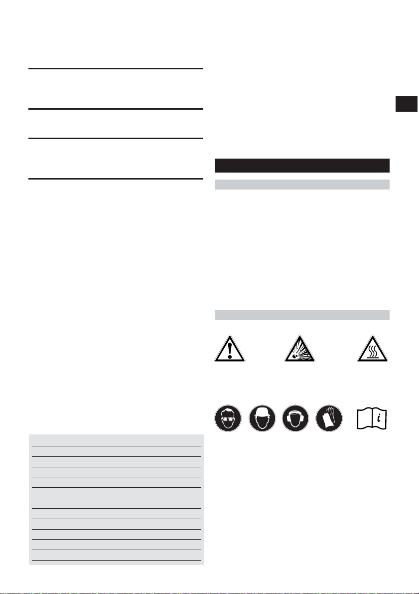
8.2.2 Cleaning the piston guide
-WARNING-
Check that there are no cartridges in the tool.
Check that there are no fasteners in the tool or magazine.
-WARNING-
Parts of the tool may become very hot after a period of
use. Protective gloves must be worn if the following
maintenance procedure is carried out before the tool
has been allowed to cool down.
-CAUTION-
● The tool may become hot during
operation.
● You could burn your hands.
● Wear protective gloves before
carrying out care and maintenance.
8.1 Care of the tool
Clean the casing of the tool at regular intervals with a
damp cloth.
-NOTE-
Do not use a spray or steam-cleaning system for cleaning! Never operate the tool when the ventilation slots
are unobstructed. Do not permit foreign objects to enter
the interior of the tool.
8.2 Maintenance
Check all external parts of the tool for damage at regular intervals and check that all controls operate properly.
Do not operate the tool when parts are damaged or when
the controls do not operate properly. If necessary , have
the tool repaired at a Hilti service centre.
Use the tool only with the recommended cartridges and
power settings. Use of the wrong cartridges or use of
excessively high power settings may lead to premature
failure of parts of the tool.
-CAUTION- when cleaning:
Never use grease for the maintenance/lubrication of
parts of the tool. This may lead to malfunctions. Use
only Hilti lubricant spray or a product of comparable
quality.
The residues deposited inside DX tools contain substances that may be injurious to your health:
– Do not inhale any dust or dirt while cleaning.
– Keep the dust or dirt away from foodstuffs.
–Wash your hands after cleaning the tool.
Page 17

28
1. Unscrew and remove the fastener guide (or fastener
magazine).
2. Pull the piston out of the piston guide.
3. Hold the tool with the nosepiece pointing upwards
and then pull out the piston guide release lever.
-CAUTION-
It is essential that the tool is held with the nosepiece
pointing upwards. The piston guide may otherwise fall
out.
4. Pull the piston guide out of the tool.
5. Use the large brush to clean the inside and outside
surfaces of the piston guide.
6. Use the small round brush to clean the cartridge
chamber and the adjoining holes for the power regulation pin.
7. Clean the seat of the piston guide in the tool.
8. Lubricate the slider and the collar of the piston guide
with Hilti spray.
9.Lubricate the mechanical parts inside the tool with
Hilti spray.
-NOTE-
Use of lubricants other than Hilti spray may cause damage to rubber parts.
10. Push the piston guide into the tool and close the
piston release lever while applying light pressure
to the piston guide.
-NOTE-
The lever can be closed only when the piston guide is
pressed (several mm) into the tool.
If the lever still cannot be closed, please refer to the information in section 9 “Troubleshooting”.
11. Push the piston into the fastener guide (or the fastener magazine).
12. Screw the fastener guide (or fastener magazine)
onto the piston guide as far as it will go and then
turn it back in the opposite direction until it engages.
13. Lubricate the cartridge transport mechanism by
spraying Hilti lubricant into the gap in the housing
behind the cycling grip.
14. Cycle the tool once by moving the cycling grip.
8.3 Checking the tool after care and maintenance
After carrying out care and maintenance and before loading the cartridges, check that all safety devices have
been fitted and that they function faultlessly.
9. T roubleshooting
-WARNING-
The tool must be unloaded before taking any steps to remedy faults.
Fault
Cartridge is not
transported.
Cartridge strip cannot be
removed.
Cartridge doesn't fire.
Fastener penetrates too
deeply (inadequate
fastener stand-off). a
Possible cause
Damaged cartridge strip.
Tool is damaged.
The tool is damaged or has
overheated as a result of an
excessively high fastener driving rate.
The tool is not pressed fully against
the working surface.
The cartridge strip is used up.
The magazine or fastener guide is not
screwed on far enough.
One of the cartridges is faulty.
The tool is defective or the cartridges
are faulty.
Fastener missed the steel beam.
Power setting too high.
Remedy
Change the cartridge strip
Contact Hilti.
Allow the tool to cool and then try again
carefully to remove the cartridge strip. If
still not possible, contact Hilti.
-NOTE-
Do not attempt to forcibly remove
cartridges from the cartridge strip or
from the tool.
Press the tool fully against the working
surface and pull the trigger.
Remove the used cartridge strip. Load a
new strip.
Screw the magazine farther onto the tool.
Cycle the tool and use up the remaining
cartridges.
Contact Hilti.
Mark the position of the beam. Drive
another fastener into the beam.
Reduce fastener driving power according
to the recommendations for the cartridge
or, respectively, use a less powerful
cartridge.
en
Page 18

29
Fastener does not
penetrate deeply enough
(excessive fastener
stand-off). b
Fastener head projection
varies considerably. c
Shear breakage d
The tool remains
compressed (does not
extend when pressure is
released).
The tool cannot be fired.
No fastener is driven.
The piston is worn.
The wrong piston has been fitted.
Fastener driven into the rib of the
beam.
Different thickness and/or strength of
supporting material.
Fastener driving power is too low.
The tool needs to be cleaned.
The piston is broken.
The tool is damaged.
The wrong piston has been fitted.
The tool is not cycled equally each
time, or not cycled fully.
Irregular driving power.
Fastener driven into the rib of the
beam.
The supporting material is thicker
and/or of higher strength.
The piston is sticking in the piston
stopper.
The tool needs to be cleaned.
The cartridge strip has jammed, the
tool has overheated.
Trigger pulled before the tool is fully
pressed down.
Fastener transport malfunction.
The tool needs to be cleaned.
The magazine or fastener guide is not
screwed on far enough.
The tool is damaged.
No fasteners in the tool.
Magazine fastener transport
mechanism is faulty.
No piston in the tool.
The piston is broken.
Replace the piston and piston stopper.
Check that the right combination of
piston and fastener is used.
Drive a second fastener offset from the
first.
Increase fastener driving power in
accordance with recommendations or,
respectively, use a more powerful
cartridge.
Increase fastener driving power in
accordance with recommendations or,
respectively, use a more powerful
cartridge.
Clean the tool.
Change the piston and piston stopper.
Contact Hilti.
Check that the right combination of
piston and fastener is used.
The tool must be cycled precisely over
the full movement of the grip each time.
Clean the tool. Replace the wearing
parts. Contact Hilti if irregular driving
power is still experienced.
Reposition the tool and drive another
fastener.
Check that the recommended type of
fastener is being used and then increase
driving power in accordance with recommendations for the cartridge or, respectively, use a more powerful cartridge.
Replace the piston and piston stopper.
,
Clean the tool. –
Please refer to the fault: “Cartridge
strip cannot be removed.”
Do not exceed the maximum
recommended fastener driving rate.
Press the tool down fully and then pull
the trigger.
Load fastener strips ;
check that strips are free to move;
remove any damaged or distorted
fastener strips
Clean the tool. –
Screw the magazine farther onto the tool.
Contact Hilti.
Load fastener(s) into the tool.
Contact Hilti.
Fit the piston.
Replace the piston and piston stopper.
en
Page 19

30
If these measures fail to remedy the problem, please contact Hilti.
The fastener guide
cannot be screwed on to
the tool fully.
The piston cannot be
fitted.
The piston guide cannot
be fitted.
Stiff cycling action.
The fastener guide needs to be
cleaned.
Fasteners are jammed in the fastener
guide.
The piston stopper has been inserted
the wrong way round.
The piston guide needs to be cleaned
at the end of the threaded section.
The tool, the piston guide in particular,
needs to be cleaned.
The slider projects into the piston
guide and prevents movement of the
piston.
The lever is in the closed position.
The piston guide is incorrectly
positioned.
The tool needs to be cleaned.
Use the brushes provided to clean the
fastener guide and associated parts.
lubricate with Hilti spray.
Remove the jammed fasteners.
Avoid shear breakage (see above).
Avoid missing the beam (driving the
fastener into unsupported sheet metal);
mark the position of the beams
accurately if necessary.
Unscrew and remove the fastener guide.
Fit the piston stopper the right way
round.
Clean and lubricate the thread.
Clean the fastener guide and the tool and
refit the piston.
Pull the slider forward until it can
engage.
Open the lever.
Position the piston guide correctly when
inserting it.
Clean the piston guide.
Check the piston for straightness.
Clean the tool. –
en
10. Disposal
Most of the materials from which Hilti powder-actuated tools are manufactured can be recycled. The materials
must be correctly separated before they can be recycled. In many countries, Hilti has already made arrangements
for taking back your old powder-actuated tools for recycling. Please ask your Hilti customer service department
or Hilti sales representative for further information. Should you wish to return the tool yourself to a disposal facility
for recycling, proceed as follows: Dismantle the tool as far as possible without the need for special tools. National
and international directives and regulations must be observed.
Separate the individual parts as follows:
Part/assembly
Toolbox
Outer casing
Piston
Piston stopper
Screws, small parts
Used/partly-used cartridge strips
Main material
Plastic
Plastic/synthetic rubber
Steel
Steel/plastic
Steel
Steel/plastic
Recycling
Plastics recycling
Plastics recycling
Scrap metal
Scrap metal
Scrap metal
In accordance with local regulations
Page 20

31
en
11. Warranty
Hilti warrants that the product supplied is free of defects
in material and workmanship. This warranty is valid as
long as the product is operated and handled correctly,
cleaned and serviced properly and in accordance with
the Hilti operating instructions, all warranty claims are
made within 5 years from the date of sale (invoice date)
for the tool and 1 year from the date of sale (invoice date)
for the magazine and ancillary equipment (unless other
mandatory national regulations prescribe a longer minimum period) and the technical system is maintained,
i.e. only genuine Hilti consumables, accessories and
spare parts, or those of equivalent quality, are used with
the product.
This warranty provides the free-of-charge repair or replacement of defective parts only. Parts requiring repair or
replacement as a result of normal wear and tear are not
covered by this warranty.
Additional claims are excluded, unless mandatory
national regulations prohibit such exclusion. In particular, Hilti is not obligated for direct, indirect, incidental or consequential damages, losses or expenses
in connection with, or by reason of, the use of, or inability to use the product for any purpose. Implied warranties of merchantability or fitness for a particular
purpose are specifically excluded.
Send the product and/or related parts immediately upon
discovery of a defect to the local Hilti marketing organization for repair or replacement.
This constitutes Hilti’s entire obligation with regard to
warranty and supersedes all prior or contemporaneous
comments and verbal or written agreements concerning warranties.
Confirmation of CIP testing
The Hilti DX 76
has been system and type tested. As a
result, the tool bears the rectangular PTB approval mark
showing approval number S 813. Hilti thus guarantees
compliance with the approved type. Unacceptable defects
or deficiencies, etc. determined during use of the tool
must be reported to the person responsible at the approval
authority (PTB) and to the Office of the Permanent International Commission (C.I.P.).
Noise information
as per German legislation (3, GSGV dated January 18,
1991):
The noise (power) level L
WA,1S
as per § 1 (2) 1b) applicable to the tool and, due to different workplaces depending on the application for which the tool is used, also the
noise (pressure) level L
pAImax
, at the measurement surface of 1 meter as per § 1 (2) 1e), are given in addition
to the workplace related noise emission value in accordance with the noise measurement standard. Operating
conditions and circumstances of use: most powerful cartridge power load in accordance with instructions for use
with suitable fastener or stud fired vertically downwards
into a concrete block and in accordance with the means
of measurement DIN 45635, part 34 “Measurement of
the noise emitted by machines – airborne noise, surface
sound transmission – methods – powder-actuated fastening tools”.
Noise information: Noise information with typical application*:
1b) Noise (power) level L
WA, 1S
= 117 dB (A)
workplace-relevant
emission value L
pAImax
= 114 dB (A)
1e) Noise (pressure) level L’
–
pA, 1s
= 104 dB (A)
Variations in operating conditions may cause deviations from these noise emission values.
*ENP nail with cartridge 6.8/18 M red and power level
2 on 20 mm steel with 370 N/mm
2
Page 21

Hilti Corporation
FL-9494 Schaan
Tel.:+423/2342111
Fax: +423/2342965
www.hilti.com
Hilti = registered trademark of Hilti Corp., Schaan W 2974 0305 10-Pos. 1 1 Printed in Liechtenstein © 2005
Right of technical and programme changes reserved S. E. & O.
282470 / C
 Loading...