

Page 1

<Keines>
DX36M / MX32 / MX62
Bedienungsanleitung 2–22
Operating instructions 2–22
Mode d’emploi 2–22
Manual de instrucciones 2–22
*3357*
3357
Page 2
2
Technische Daten
Leistung: Für Nagelbefestigungen auf Beton und Stahl
Gewicht: 2,4 kg
Gerätelänge: 390 mm
Kartusche: 6,8/11M in Magazinstreifen zu je 10 Kartuschen
Technical data
Performance: For fastenings to concrete and steel
Weight: 2.4 kg
Tool length: 390 mm
Power load: 6.8/11M in cartridge in magazines strips of 10
Données techniques
Rendement: Pour clouages sur béton et acier
Poids: 2,4 kg
Longueur: 390 mm
Cartouches: 6,8/11M en chargeurs de 10 cartouches
Datos técnicos
Aplicación: Fijaciones de clavos sobre hormigón y acero
Peso: 2,4 kg
Longitud: 390 mm
Cartucho: 6,8/11M en peines de 10 cartuchos
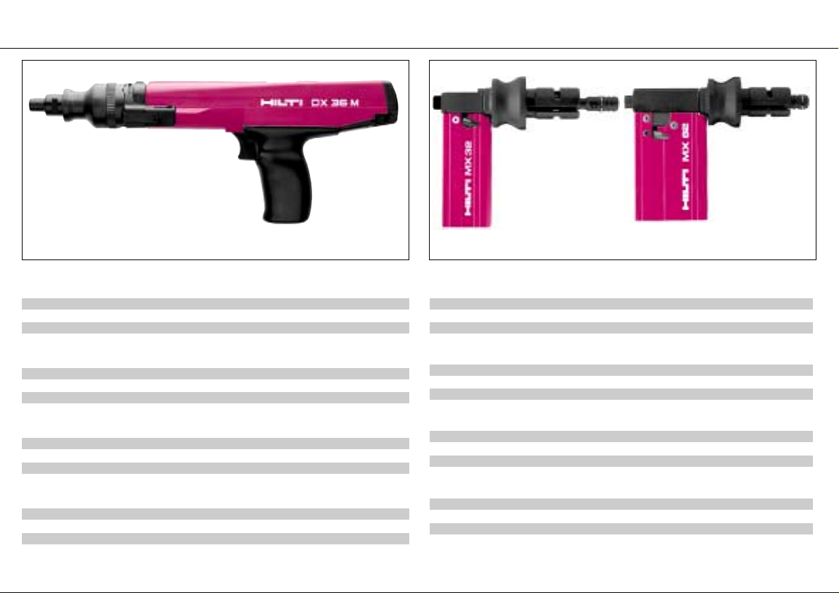
Bolzensetzgerät DX36M / DX36M Fastening Tool /
Appareil de scellement DX36M / Herramienta de fijación DX36M
Nagelmagazin MX32M, MX62 / Fastener magazine MX32, MX62 /
Chargeurs de clous MX32, MX62 / Cargador de clavos MX32, MX62
Awarded the British
Standards Institute
Kit Mark BS 4078
Part 2
Technische Daten MX32 MX62
Gewicht: 0,8 kg 1,3 kg
Magazinkapazität: 10 Stück 10 Stück
Nagellänge: max. 32 mm max. 62 mm
Technical data MX32 MX62
Weight: 0.8 kg 1.3 kg
Magazine capacity: 10 fasteners 10 fasteners
Fastener length: max. 32 mm max. 62 mm
Données techniques MX32 MX62
Poids: 0,8 kg 1,3 kg
Capacité du chargeur: 10 clous 10 clous
Longueur de clous: max. 32 mm max. 62 mm
Datos técnicos MX32 MX62
Peso: 0,8 kg 1,3 kg
Capacidad del cargador: 10 clavos 10 clavos
Longitud de clavos: máx. 32 mm máx. 32 mm
Page 3

4
Safety precautions
Failure to follow these precautions could result in personal injury.
▲
!
Warnings
1. Never use this tool unless you have received proper instruction on its safe use. For assistance, contact your local Hilti sales representative.
2. Always use this tool in strict accordance with the operating instructions and always keep
them with the tool.
3. Do not point the tool at yourself or any bystander.
4. Never cock the tool against your hand or other part of your body.
5. Operator and bystanders must wear appropriate eyewear and hard hats while tool is in use.
Safety precautions
6. Always use the stabilizer/guard whenever possible.
7. Never leave a loaded tool unattended. Always unload the tool before any cleaning or maintenance work, before remedying any defects or malfunctioning, before storing the tool after
finishing work, before work breaks and before changing parts.
8. Wear ear protection when working in confined areas.
9. Always inspect tool for proper operation before using. Do not use a tool that is incomplete
or does not operate properly.
10. Keep arms flexed when operating tool (do not stiff arm). If you feel discomfort, discontinue use.
11. Always hold tool perpendicular to work surface and base material when making
fastening.
12. Always use genuine Hilti fasteners, cartridges and spare parts, or those of equivalent
quality.
13. Do not attempt to pry cartridge from cartridge strip or from tool.
14. Always do the following if cartridge misfires or fails to ignite:
■ Keep tool against work surface for 30 seconds.
■ If cartridge still does not ignite, withdraw tool from work surface, taking care that tool is
not pointed at user or bystanders.
■ Cycle the tool so that the next cartridge is transported. Use up the remaining cartridges
in the strip; remove used cartridge strip and dispose of it in such a way that it can neither
be used again nor misused.
15. Never fasten through an existing hole, except when otherwise recommended by Hilti, e.
g. DX-Kwik.
16. Always keep tool and cartridges locked in a container and in a safe place when not in use.
17. Do not make fastenings in an explosive or flammable atmosphere, except when tool is
approved for such use.
18. Always consult application guidelines.
19. Make sure that no one stands behind/below fastening location when making fastenings
20. Do not disassemble tool when it is hot.
21. Never exceed the recommended setting frequency (number of fastenings per hour).
22. Always remove the cartridge strip during work breaks (< 30 seconds).
General notes
23. Never re-drive fasteners.
24. Observe the relevant national regulations, especially those regarding accident prevention.
Through-shot and ricochet prevention:
The piston principle employed results in low fastener velocity and dissipation of excess driving power.
Contact pressure safety device:
The pressure required to overcome the cocking force and movement prevents a loaded tool
from being fired if it is not pressed against a firm work surface. The tool can only be fired if
the contact pressure safety device is pressed to over-come a movement of 16 mm and a
minimum force of 1 10 N.
Technical description
The DX36 M is a tool which drives nails and threaded studs into concrete and steel. The
DX36 Mworks on the piston principle which gives the assurance of an optimum of operator
safety and fastening reliability. The cartridges are transported automatically for faster and more
economical fastening. In addition, the DX 36M can also be equipped with a fastener magazine.
Depending on the required length of nail, the MX32 for nails up to 32 mm long or the MX62 for
nails up to 62 mm long can be used.
As for all Hilti DX fastening tools, the DX36M, the fasteners and the cartridges have been designed for each other as a technical system. This means that fastening with this tool will only be
quick, accurate and troublefree if the fasteners and cartridges designed specifically for this tool
are used. Fastening recommendations drawn up by Hilti are only valid if this technical system is
used.
The recommended maximum fastening rate is 600 fastenings per hour. This tool is not approved
for use in explosive atmospheres.
This fastener magazine has been designed as an accessory for the DX36M. It greatly increases
the fastening speed and ease of operation of the DX36M. lt is a great advantage when used for
repetitive fastenings of all kinds
Page 4
7
Handhabung Standardgerät / Handling of standard tool / Maniement de l’appareil standard / Manejo de la herramienta estándar
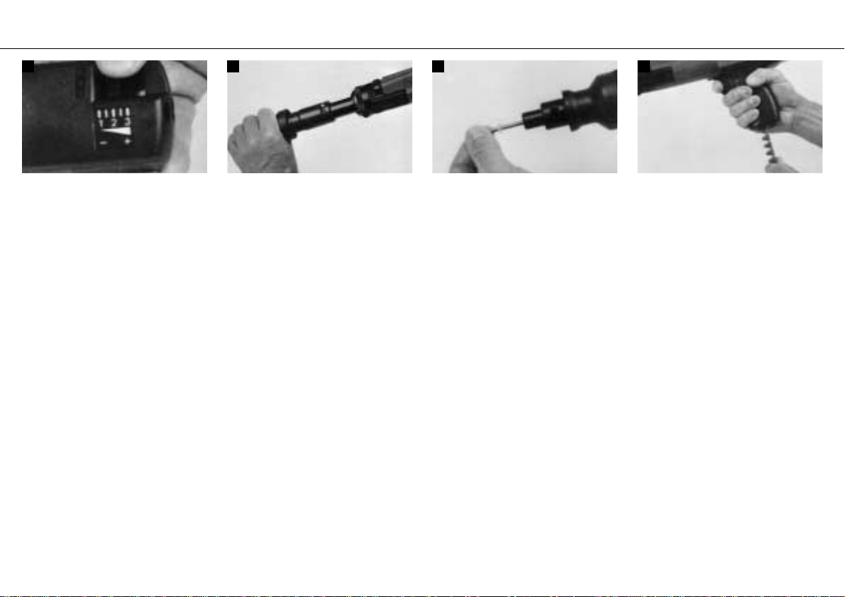
1 2 3 4
Geräteleistung einstellen durch Drehen des
Regulierbolzens.
1 = min. Leistung
3 = max. Leistung
Adjust the driving power by turning the regulating thumbwheel.
1 = min. driving power
3 = max. driving power
Tourner la molette pour régler la puissance
de l'appareil.
1 = puissance min.
3 = puissance max.
Girar la ruedecilla para regular la potencia de
la herramienta.
1 = potencia min.
3 = potencia max.
Einsatz ganz nach vorne ziehen und wieder
zurückstossen.
Hinweis: Lässt sich der Einsatz schwer ausziehen, Schlitz mit Hilti Spray leicht ein-
sprühen und Einsatz einige Male hin- und
herschieben.
Pull out the barrel assembly fully and push it
back again.
Note: If the barrel assembly is stiff, spray the
slot sparingly with Hilti lubricant and pull out
and push back the barrel assembly several
times.
Tirer à fond l'ensemble canon vers l'avant,
puis le repousser à fond.
Nota: Si l'ensemble canon coulisse difficilement, lubrifier légèrement la rainure avec un
peu de spray Hilti, puis faire coulisser l'ensemble canon plusieurs fois dans les 2 sens.
Mover el conjunto completamente hacia adelante y empujarlo atrás otra vez.
Nota: Si se mueve con dificultad, lubricar la
ranura levemente con el spray Hilti y mover el
conjunto varias veces hacia adelante y hacia
atrás
Nagel einschieben, bis Rondelle im Gerät
gehalten wird.
Insert the fastener until the washer is held in
the fastener guide.
Introduire le clou jusqu'à ce que la rondelle
tienne bien dans l'appareil.
Insertar el clavo en la boca hasta que la arandela quede sujeta en la herramienta.
Kartuschenmagazin von unten ganz in den
Griff einschieben.
Insert the cartridge magazine into the base of
the grip and push it in until it is flush with the
grip.
Enfoncer à fond le chargeur de cartouches
dans la poignée par le bas.
Introducir completamente el peine de car-
tuchos en la empuñadura desde abajo.
Page 5
8
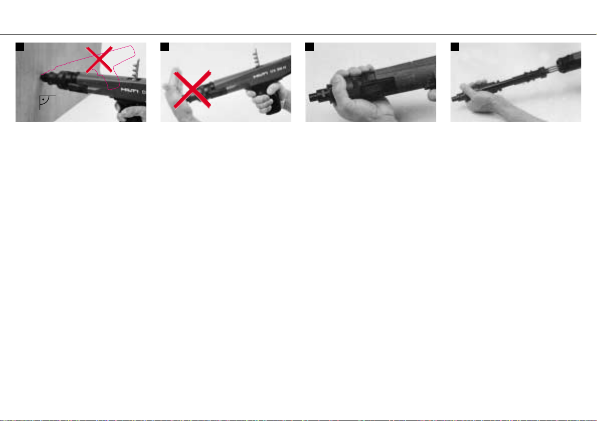
5 6 1 2
Befestigen: Gerät rechtwinkling zum Befesti-
gungsuntergrund ansetzen, anpressen und
Abzug betätigen. Durch Ausziehen des Einsatzes und wieder zurückstossen desselben
bis zum Einrasten, wird das Kartuschenmagazin automatisch um eine Kartusche weitertransportiert.
Driving the fastener: Hold the tool at right
angles to the material in which the fastener is
to be driven, press it firmly against the working
surface and pull the trigger. By pulling out the
barrel assembly and pushing it back again
until it clicks into position, the magazine will
automatically be advanced by one cartridge.
Fixation: placer l’appareil bien perpendiculairement au support, l’appuyer et presser la
détente. Un simple va-et-vient avant-arrière
du canon jusqu’à ce qu’il se verrouille
déclenche l’avance automatique du chargeur
d’une cartouche.
Impulsión del clavo: Mantener la herramienta perpendicular al material en que se
quiere fijar el clavo, apretarla con fuerza contra la superficie de trabajo y disparar. Tirando
el conjunto hacia adelante y empujandolo
atrás que se enclave, el peine avanza
automáticamente al siguiente cartucho.
Vorsicht: Bolzenführung nie mit der Handfläche zurückdrücken; Verletzungsgefahr.
Caution: Never push back baseplate by
hand. There is a risk of injury.
Atention: Ne jamais repousser le canon
avec la paume de la main sous peine de se
blesser.
Atención: Jamás haga la presión de
contacto contra su mano. Corre el riesgo
de accidentarse.
Durch Drehen des Ringes um 45°wird der
Anschlag ausgeschwenkt und der Einsatz
kann aus dem Gerät gezogen werden. Wenn
Anschlag klemmt, denselben mit Hilfe eines
Nagels ausschwenken.
Give the ring a quarter turn to hinge out the
stop. The barrel assembly can then be pulled
out of the tool. If the stop sticks, ease it out
with the aid of a fastener.
Tourner la bague de 45° pour faire pivoter et
dégager la butée, et sortir l'ensemble canon
de l'appareil. Si la butée coince, utiliser un
clou pour la faire pivoter.
Dando un cuarto de vuelta al anillo, se puede
pivotar el tope y retirar el conjunto de la herramienta. Si el tope está atascado, utilizar un
clavo para hacerlo pivotar.
Einsatz aus Gerät gleiten lassen. Sollte der
Einsatz verklemmt sein, kann er durch ruckartiges Herausziehen gelöst werden.
Let the barrel assembly slide out of the housing. If the barrel assembly sticks, it can be
freed by pulling it with a jolt.
Sortir l'ensemble canon de l'appareil en le
faisant glisser. Si l'ensemble canon coince, le
dégager par secousses.
Hacer deslizar el conjunto fuera de la herramienta. Si está atascado, soltarlo mediante
un tirón repentino.
Wechseln des Kolbens und Bolzenführung / Changing the piston and fastener guide /
Remplacement du piston et du canon / Cambio del pistón y guía-clavos
Page 6
9
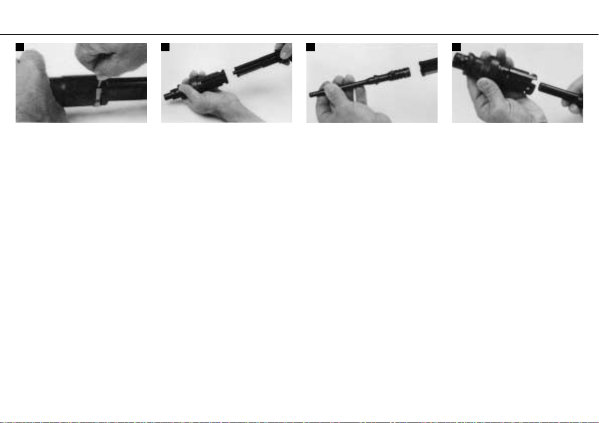
3 4 5 6
Federbügel mit Nagel entfernen.
Lever off the spring clip with a fastener.
Retirer l'étrier-ressort à l'aide d'un clou.
Retirar el estribo con un clavo.
Standplatte mit Bolzenführung von der Kolbenführung abziehen.
Separate the fastener guide and piston guide.
Extraire l'embase et le canon du guide-piston.
Extraer la base con el guía-clavos del guíapistón.
Kolben aus der Kolbenführung ziehen.
Pull the piston out of its guide.
Dégager le piston de son guide.
Sacar el pistón del guía-píston.
Bolzenführung aus der Standplatte gleiten
lassen.
Hinweis: Bei stark verschmutztem Gerät
Bolzenführung mit dem Kolben aus Standplatte stossen.
Let the fastener guide slide out of the baseplate.
Note: In tools having a heavy carbon buildup, use the piston to push the fastener guide
out of the baseplate.
Incliner l'embase de manière à faire descendre le canon.
Remarque: si l'appareil est fortement encrassé, chasser le canon de l'embase en s'aidant
du piston.
Inclinar la base para hacer salir el guía-clavos.
Nota: Si la herramienta tiene una acumulación de carbón, expulsar el guía-clavos de la
base mediante el pistón.
Page 7

10
1 2 3 4
Bolzenführung in Standplatte einsetzen.
Hinweis: Bolzen am Kolben sowie Schlitz in
Standplatte und Kolbenführung müssen übereinstimmen.
Insert the fastener guide into the baseplate.
Note: The pin on the piston and the slot in the
baseplate and piston guide must align.
Remettre le canon dans l'embase.
Remarque: Le tenon sur le piston et la rainure dans l'embase et le guide-piston doivent
être alignés.
Introducir el guía-clavos en la base.
Nota: El perno en el pistón, la ranura en la
base y el guía-pistón deben estar alineados.
Kolben in Kolbenführung bis zum Anschlag
einschieben.
Push the piston into the piston guide as far as
it will go.
Enfoncer le piston à fond dans son guide.
Introducir el pistón en el guía-pistón hasta el
tope.
Standplatte mit Bolzenführung auf Kolbenführung stecken. Federbügel in Ausnehmung
drücken.
Slide the baseplate and fastener guide onto
the piston guide. Snap the spring clip into
place.
Engager l'embase avec le canon sur le guidepiston. Remettre l'étrier-ressort, en force,
dans son logement.
Montar la base con el guía-clavos sobre el
guía-pistón y presionar el estribo en su ranura.
Einsatz in Gerät einführen. Schlitz im Einsatz
muss mit dem Anschlag übereinstimmen.
Insert the barrel assembly into the tool. The
slot in it must align with the stop.
Réintroduire l'ensemble canon dans l'appareil. La rainure de l'ensemble canon doit
être alignée sur la butée.
Introducir el conjunto en la herramienta. La
ranura en el conjunto debe coincidir con el
tope.
Zusammenbau / Assembly / Remontage / Montaje
Page 8

11
5
Anschlag in Öffnung in Hülse drücken und
Verschluss zurückdrehen.
Press the stop into the opening in the sleeve
and turn back the ring to lock.
Remettre la butée en force dans son orifice
dans la douille et tourner pour reverrouiller.
Presionar el tope a la abertura en el manguito
y volver a girar para engranar.
Hinweis: Defekter Anschlag kann in ausgeschwenkter Position unter nach vorne ziehen,
demontiert werden.
Note: A damaged stop can be removed in the
hinged-out position by pulling it forward.
Remarque: Si la butée est défectueuse, elle
peut être démontée: après I'avoir fait pivoter,
la tirer en avant.
Nota: Un tope defectuoso puede ser retirado
en la posición pivotada, tirándolo hacia adelante.
Page 9

12
1 2 3 4
Durch Drehen des Ringes um 45° wird der
Anschlag ausgeschwenkt und der Einsatz
kann aus dem Gerät gezogen werden. Wenn
der Anschlag klemmt, denselben mit Hilfe
eines Nagels ausschwenken.
Turn the locking ring through 45°. This hinges
out the stop, allowing the barrel assembly to
be removed from the tool. If the stop sticks,
hinge it out with the aid of a fastener.
Tourner la bague de 45° pour faire pivoter et
dégager la butée, sortir l'ensemble canon de
l'appareil.
Si la butée coince, utiliser un clou pour la faire pivoter.
Dando un cuarto de vuelta al anillo de bloqueo, se puede pivotar el tope y retirar el
conjunto de la herramienta.
Si el tope está atascado, utilizar un clavo para
hacerlo pivotar.
Einsatz aus dem Gerät gleiten lassen.
Ist der Einsatz verklemmt, kann er durch
ruckartiges Herausziehen gelöst werden.
Slide the barrel assembly out of the tool.
If the barrel assembly sticks, it can be
released by giving it a sudden pull.
Sortir l'ensemble canon de l'appareil en le
faisant coulisser.
Si l'ensemble canon coince, le dégager
par secousses.
Hacer deslizar el conjunto fuera de la herramienta.
En caso que el conjunto estuviese atascado, se puede soltar mediante un tirón
repentino.
Federbügel mit einem Nagel entfernen.
Ease off the spring clip using a fastener.
Retirer l’étrier-ressort à laide d’un clou.
Retirar el estribo de resorte mediante un
clavo.
Standplatte und Bolzenführung von der Kolbenführung abziehen.
Kolben aus der Kolbenführung ziehen (für
Magazinausrüstung kann die gleiche Kolbenführung verwendet werden).
Remove the baseplate and the fastener guide
from the piston guide.
Pull the piston out of its guide. (The same
piston guide can be used with the magazine.)
Extraire l'embase et le canon du guidepiston.
Dégager le piston de son guide (sur l'appareil
avec chargeur, il est possible d'utiliser le
même guide-piston).
Extraer la base con el guía-clavos del guíapistón.
Sacar el pistón del guía-pistón. (El mismo
guía-pistón puede utilizar con el cargador.
Handhabung Magazingerät / Handling of magazine tool / Maniement de l’appareil avec chargeur / Manejo de la herramienta con cargador
Page 10

13
5 6 7 8
Spezial-Kolben 36/MX für das Nagelmagazin
MX32/MX62 in die Kolbenführung einschieben.
Kolbenzuordnung:
Gerät DX36 M = Kolben 36/DN
Magazin MX32, MX62 = Kolben 36/MX
Insert the special piston 36/MX for the MX 36/
MX62 fastener magazine into the piston
guide.
Matching piston:
DX36M = 36/DN piston
MX32, MX 62 magazine = 36/MX piston
Enfoncer le piston spécial 36/MX prévu pour
le chargeur de clous MX32/MX62 dans le
guide-piston.
Types de pistons:
Appareil DX36 M = piston 36/DN
Chargeurs MX32, MX62 = piston 36/MX
Insertar el pistón especial 36/MX para el cargador MX32 en el guía-piston.
Tipos de pistón:
DX36 M = Pistón 36/DN
Cargador MX32, MX62 = Pistón 36/MX
Nagelmagazin mit der Hülse auf die Kolbenführung stecken und den Federbügel in die
Ausnehmung drücken.
Hinweis: Schlitz im Einsatz muss mit dem
Anschlag übereinstimmen.
Push the fastener magazine with sleeve onto
the piston guide and snap the spring clip into
its recess.
Note: The slot in the barrel assembly must
align with the stop.
Enfoncer le chargeur de clous avec le manchon sur le guide-piston et remettre l'étrierressort en force, dans son logement.
Remarque: La rainure de l'ensemble canon
doit être alignée sur la butée.
Insertar el cargador de clavos el manguito
sobre el guía-pistón y presionar el estribo de
resorte en su posición.
Nota: La ranura en el conjunto debe coincidir
con el tope.
Einsatz in das Gerät stecken.
Insert the barrel assembly into the tool housing.
Réintroduire l'ensemble canon dans l'appareil.
Insertar el conjunto en la herramienta.
Anschlag in die Öffnung der Hülse drücken
und den Verschluss zurückdrehen.
Press the stop into the opening and turn the
locking ring to close.
Remettre la butée en force dans son orifice
dans le manchon et tourner pour reverrouiller.
Presionar el tope adentro de la abertura y girar el anillo de bloqueo para cerrar.
Page 11

14
1 2 3 4
Einsatz ganz nach vorne ziehen und wieder
zurückstossen.
Hinweis: Nagelmagazin an dem Repetiergriff
halten, um ein Verkanten des Einsatzes zu
verhindern.
Pull the barrel assembly forward as far as it
will go and then push it back.
Note: Hold the guard sleeve on the magazine
to avoid tilting (angulating) the barrel assembly.
Imprimer un mouvement de va-et-vient
avant-arrière à l'ensemble canon.
Remarque: Tenir le chargeur de clous par le
manchon d'armement pour éviter que l'ensemble canon ne se désaxe.
Tirar el conjunto completamente hacia adelante y empujarlo otra vez hacia atrás.
Nota: Sostener el cargador completamente
arriba para evitar un ladeo del conjunto.
Raste am Nagelmagazin mit dem Daumen
nach oben drücken...
Press forward the catch on the fastener
magazine with your thumb…
Appuyer avec le pouce le cliquet du chargeur
de clous vers le haut…
Presionar hacia adelante el bloqueo del cargador de clavos mediante el pulgar luego…
…und das Magazingehäuse nach hinten
ziehen bis es einrastet.
…and pull down the magazine housing until
it snaps into place.
…tirer le boîtier du chargeur vers l'arrière
jusqu'à ce qu'il s'encliquète.
…tirar la carcasa del cargador hacia abajo
hasta que la misma se encaje.
Elementstreifen in die Nut legen (gemäss
Darstellung im Magazin).
Put the fastener strip into its groove.
Introduire la bande-chargeur d'éléments dans
la rainure (dans le chargeur comme représenté sur la photo).
Introducir el peine de clavos en la ranura del
cargador (ver la foto).
Handhabung Laden / Operation (loading) / Maniement (chargement) / Modo de empleo (carga)
Page 12

15
5 6 7
Durch Betätigung der Raste oder einfaches
Zudrücken Magazin schliessen.
Press the catch to close the magazine.
Actionner le cliquet ou appuyer simplement
pour refermer le chargeur.
Presionar el bloqueo o simplemente empuje
para cerrar el cargador.
Hinweis: Der Arbeitsbereich des Nagelmagazins geht bis ± 90° zur Grundstellung. Raststellungen bei 0° und ± 90°. Bei 180° ist die
Zerlegestellung.
Ist der letzte Nagel verbraucht, tritt eine
Anpress-Sperre in Kraft.
Note: The fastener magazine functions in
positions up to ± 90° to the grip (additional
locking positions are 0° and ± 90°). 180° is
the disassembly position. If the last nail has
been used, a detent prevents the tool from
being pressed down and cocked.
Nota: Plage de travail du chargeur de clous:
± 90°par rapport à sa position initiale. Positions d’encliquetage: 0°et ± 90°. 180°= position de démontage. Le tir du dernier clou
déclenche un dispositif de blocage de la mise
en appui.
Nota: Posición de trabajo del cargador: ± 90°
de su posición inicial. Posiciones de bloqueo
o°y 90°.
Posición de desmontaje :180° al fijar el últi mo clavo se bloquea al sistema de presión de
contacto.
Hinweis: Sollte das Magazin schwer zu
bewegen sein, mit Hilti-Spray leicht einsprühen.
Note: If the movement of the magazine is
stiff, spray it sparingly with Hilti Iubricant.
Remarque: En case de grippage du chargeur, le lubrifier légèrement avec du spray
Hilti.
Nota: En caso de atasco del cargador lubrificar ligeramente con spray Hilti.
Vorsicht: Bolzenführung nie mit der Handfläche zurückdrücken; Verletzungsgefahr.
Caution! Never push back baseplate by
hand. There is a risk of injury.
Attention: Ne jamais repousser le canon
avec la paume de la main sous peine de se
blesser.
Atención: Jamás haga la presión de contacto contra su mano. Corre el riesgo de
accidentarse.
Page 13

16
1 2 3 4
Magazin nach oben drehen (180°).
Twist magazine to point upwards (180°).
Faire pivoter le chargeur jusqu’en haut
(180°).
Girar hacia arriba el cargador 180°.
Magazin von Gerät herausziehen.
Pull magazine out of tool.
Enlever le chargeur de l’appareil.
Retirar el cargador de la herramienta.
Einzelsetzausrüstung in Gerät einführen.
Insert equipment for single fastenings into tool.
Introduire l’embase simple dans l’appareil.
Introducir la base standard en la herramienta.
Bis zum Anschlag einführen, dann links oder
rechts bis zum Einrasten drehen.
Push in as far as it will go, then turn left or
right until it clicks into place.
L’introduire à fond, puis la tourner à gauche
ou à droite jusqu’à ce qu’elle s’encliquète.
Presionar hasta el fondo y girar a derecha o
izquierda hasta que haga «click».
Umbau auf Einzelausrüstung / Conversion for single fastenings / Transformations pour enlever le chargeur / Montaje de la base standard
Page 14

17
Das Gerät sollte mindestens einmal pro
Woche bzw. unmittelbar nach jeder grösseren Anzahl gesetzter Nägel (ca. 3000 Befestigungsvorgänge) gereinigt werden.
1. Zerlegen wie beschrieben.
2. Teile mit den entsprechenden Bürsten reinigen.
3. Gereinigte Teile leicht mit Hilti Spray einsprühen.
4. Zusammenbau des Gerätes.
Gehäuse
Housing
Corps
Carcasa
Kolbenführung
Piston guide
Guide-piston
Guía-pistón
Standplatte
Baseplate
Embase
Base
Bolzenführung
Fastener guide
Canon
Guía-clavos
Kolbn
Piston
Piston
Pistón
The tool must be cleaned at least once a week
or immediately after driving a large number of
fasteners (approx. 3,000 fastenings).
1. Disassemble tool as previously described.
2. Clean parts with suitable brushes.
3. Spray cleaned parts sparingly with Hilti
lubricant.
4. Assemble tool.
L'appareil devrait être nettoyé au moins une
fois par semaine ou immédiatement après un
certain nombre de clouages (3000 fixations
environ).
1. Démonter l'appareil comme décrit.
2. Nettoyer les pièces avec les brosses correspondantes.
3. Lubrifier légèrement les pièces nettoyées
avec du spray Hilti.
4. Remonter l'appareil.
La herramienta debe ser limpiada al menos
una vez a la semana, o inmediatamente
después de un gran número de fijaciones
(aproximadamente 3000).
1. Desmonte la herramienta como se ha
descrito.
2. Limpie las piezas con las escobillas adecuadas.
3. Pulverice las piezas limpias con Hilti spray.
4. Monte de nuevo la herramienta.
Bolzenführung / Magazin
Fastener guide / Magazine
Canon / Chargeur
Guía-clavos / Cargador
Hülse
Sleeve
Manchon
Manquito
Diese Teile dürfen vom Benützer nur durch
Original Hilti-Teile ersetzt werden.
Pflege und Wartung / Cleaning and servicing / Nettoyage et entretien / Limpieza y mantenimiento
Die folgenden rot markierten Teile sind mit den mitgelieferten Reinigungsbürsten zu säubern.
Clean the surfaces marked in red on the following parts with the supplied brushes.
Nettoyer les pièces ci-dessous (entourées de rouge) à l'aide des brosses jointes à l'appareil.
Limpiar todas las piezas marcadas en rojo con las escobillas que vienen de la caja de la herramienta.
Page 15

18
Anwendungshinweise / Application notes / Directives d’application / Modo de aplicación
X-ZF / X-DNI Nagel (Beton/Stahl)
X-ZF-/X-DNI nail (concrete/steel)
Clou X-ZF-/X-DNI (beton/acier)
X-ZF-/X-DNI clavo (Hormigón / Acero)
X-EDNI-Nagel (Stahl)
X-EDNI-nail (steel)
Clou X-EDNI (acier)
X-EDNI-Clavo (Acero)
Bolzen für Beton oder Stahl
Studs for concrete or steel
Goujons pour béton ou acier
Pernos para Hormigón o Acero
Nagellängen auf Beton:
Eindringtiefe (ET) 27 ± 5 mm
+ Materialdicke (MD) ;
= Schaftlänge
Nail length for concrete:
Penetration depth (ET) 27 ± 5 mm
+ material thickness (MD)
= shank length
Longueurs des clous sur béton:
Profondeur d'implantation (ET) 27 ± 5 mm
+ épaisseur matériau (MD)
= longueur de tige
Longitud del clavo en hormigón:
Profundidad de penetración (ET) 27 5 mm
+ espesor del material a fijar (MD)
= longitud del clavo
Nagellängen auf Stahl:
Eindringtiefe (ET) 22 ± 5 mm
(Nagelspitze muss vorstehen)
+ Materialdicke (MD)
= Schaftlänge
Stahldicke (SD) = min. 4 mm, max. 10 mm
Nail length for steel:
Penetration depth (ET) 22 ± 5 mm
(nail point must protrude)
Steel thickness (SD) = 4 mm, = 10 mm
+ material thickness (MD)
= shank length
Longueurs des clous sur acier:
Profondeur d'implantation (ET) 22 ± 5 mm
(la pointe des clous doit dépasser)
Épaisseur d'acier (SD) = 4 mm, = 10 mm
+ épaisseur matériau (MD)
= longueur de tige
Longitud del clavo en acero:
Profundidad de penetración (ET) 22 ± 5 mm
(La punta del clavo debe traspasar)
+ espesor del material a fijar (MD)
= longitud del clavo
Eindringtiefe (ET) 12 ± 2 mm
+ Materialdicke (MD)
= Schaftlänge (SL)
Stahldicke (SD) = 4 mm
Penetration depth (ET) 12 ± 2 mm
+ material thickness (MD)
= shank length (SL)
Steel thickness (SD) = min.4 mm
Profondeur d'implantation (ET) 12 ± 2 mm
+ épaisseur materiau (MD)
= longueur de tige (SL)
épaisseur d'acier (SD) = 4 mm
Longitud del clavo an acero (ET) 12 ± 2 mm
+ espesor del material a fijar (MD)
= Longitud del clavo (SL)
Espesor del acero (SD) = min. 4 mm
Eindringtiefe:
Beton: 27 ± 5 mm
Stahl: 12 ± 2 mm
Penetration depth:
Concrete: 27 ± 5 mm
Steel:12 ± 2 mm
Profondeur d’implantation:
Béton: 27 ± 5 mm
Acier: 12 ± 2 mm
Profundidad de penetración:
Hormigón: 27 ± 5 mm
Acero:12 ± 2 mm
Kartuschen / Cartridges / Cartouches / Cartuchos
Bestell-Bezeichnung Farbe Ladung
Designation Colour Energy
Référence Couleur Charge
Referencia Color Potencia
6.8/11M grün grün/green/verte/verde schwache/light/faible/baja
6.8/11M gelb gelb/yellow/jaune/amarillo mittlere/medium/moyenne/media
6.8/11M rot rot/red/rouge/rojo sehr starke/very heavy/très forte/alta
19
Page 16

Sonderausrüstung / Special equipment / Equipment spécial / Equipos especiales
Sonderausrüstung für Dämmelemente von
40–80 mm:
Special equipment for insulation fasteners
from 40 to 80 mm long:
Equipement spécial pour clous d'isolation de
40 à 80 mm:
Equipo especial para espigas de aislamiento
de 40 a 80 mm:
Kolben 36/IE
Piston 36/IE
Piston 36/IE
Pistón 36/IE
Sonderausrüstung für Dämmelemente von
40–120 mm:
Special equipment for insulation fasteners
from 40 to 120 mm long:
Equipement spécial pour clous d'isolation de
40 à 120 mm:
Equipo especial para espigas del aislamiento
de 40 a 120 mm:
Kolben 36/IE
Piston 36/IE
Piston 36/IE
Pistón 36/IE
Sonderausrüstung DX-Kwik:
Special equipment for DX Kwik:
Equipement spécial DX-Kwik:
Equipo especial para DX-Kwik:
Kurz vorbohren / Element einsetzen / Fertig
Drill briefly / drive fastener / finished
Préperçage rapide / scellement / fixation terminée
Taladrar / Disparar / Fijación terminada
X-M8H / X-CR M8 Gewindebolzen
X-M8H / X-CR M8 threaded stud
Goujon fileté X-M8H / X-CR M8
Pernos X-M8H / X-CR M8
Bolzenführung 36/IE
Piston guide 36/IE
Canon 36/IE
Guía-clavo 36/IE
Bolzenführung 36/IE
Piston guide 36/IE
Canon 36/IE
Guía-clavo 36/IE
X-IE 60
X-IE 120
Standplatte 36/IE
Baseplate 36/IE
Embase 36/IE
Base 36/IE
X-DNH / X-DKH Nagel
X-DNH / X-DKH nail
Clou X-DNH / X-DKH
Clavos X-DNH / X-DKH
Zusatzstandplatte (Gummi)
für Standplatten 36/S13 und 36/S16
Rubber stabilizer
for 36/S13 and 36/S16 baseplates
Embase additionnelle (caoutchouc)
pour embase 36/S13 et 36/S16
Base adicional (goma)
para base 36/S13 y 36/S16
36/S19 Standplatte
verwendbar für Rondellen R23/R36
36/S19 baseplate
for use with R23 and R36 washers
36/S19 embase
utilisable pour rondelles R23 et R36
36/S19 base
para uso con arandelas R23/R36
Bolzenführung 36/HSN kpl.
Piston guide 36/HSN assy
Canon 36/HSN
Guía-clavo 36/HSN
Kolben 36/HSN
Piston 36/HSN
Piston 36/HSN
Pistón 36/HSN
EDNK Nagel
EDNK nail
Clou EDNK
Clavos EDNK
Page 17

20
CIP-Prüfbestätigung
Das Hilti DX36M ist bauartzugelassen und systemgeprüft. Aufgrund dessen ist das Gerät mit dem
Zulassungszeichen der PTB in quadratischer Form mit der eingetragenen Zulassungsnummer S801
versehen. Damit garantiert Hilti die Übereinstimmung mit der zugelassenen Bauart.
Unzulässige Mängel, die bei der Anwendung festgestellt werden, sind dem verantwortlichen Leiter der Zulassungsbehörde (PTB) sowie dem Büro der Ständigen Internationalen
Kommission (C.I.P.) zu melden.
Lärminformation nach der 3. GSGV vom 18. Januar 1991
Als Gerätekennwerte werden der Schalleistungspegel L
WA, 1S nach § 1 (2) 1b) sowie wegen der je
nach Anwendung unterschiedlichen Arbeitsplätze der Messflächenschalldruckpegel LpA, Imax in
1 m Abstand nach § 1 (2) 1e) angegeben, zusätzlich der arbeitsplatzbezogene Emissionswert nach
der Messnorm. Betriebszustand und Aufstellbedingungen – stärkste bestimmungsgemäss zu verwendende Ladung mit angepasstem Setzbolzen, Auslösung auf Betonblock senkrecht nach unten
– sowie die Messtechnik entsprechend DIN 45635, Teil 34 «Geräuschmessung an Maschinen –
Luftschallemission, Hüllflächen-Verfahren – Bolzensetzwerkzeuge».
Lärminformationen bei roter Kartusche und Maximalleistung:
1b)Schalleistungspegel LWA,1S = 105 dB (A)
arbeitsplatzbezogener Emissionswert LpA, Imax = 100 dB (A)
(gemessen am Ort der Ohren der Bedienungsperson)
1e)Messflächenschalldruckpegel L’pA, Imax = 92 dB (A)
Abweichende Arbeitsbedingungen können zu anderen Emissionswerten führen.
Hinweis für Deutschland
Das zusätzliche Prüfzeichen (siehe Bild) dokumentiert, ab wann das Gerät zum
Gebrauch freigegeben ist. Es gibt das Quartal des Verkaufs oder das der letzten
Wiederholungsprüfung an. Die Jahreszahl steht im kleinen Quadrat und das Quartal
in dem Dreieck, das zur Laufmündung zeigt. Zwei Jahre nach dem angegebenen
Quartal wird das Zeichen ungültig. Dann ist das Gerät dem Hersteller oder dessen Beauftragten zur erneuten Prüfung vorzulegen. Bei wesentlichen Funktionsmängeln
ist das Gerät unverzüglich zur Prüfung vorzulegen oder sicher zu entsorgen.
Confirmation of CIP testing
The Hilti DX36M has been system and type tested. As a result, the tool bears the PTB approval
mark of square shape showing approval number S801. In this way, Hilti guarantees compliance
with the approved type.
Unacceptable/inadmissible defects, deficiencies, etc. that are determined during use of
the tool must be reported to the manager responsible at the approval authority (PTB) and
to the Office of the Permanent International Commission (C.I.P.).
Noise information as per German legislation (3. GSGV dated January 18, 1991)
The noise (power) level LWA, 1S as per § 1 (2) 1b) applicable to the tool and, due to different workplaces depending on the application for which the tool is used, also the noise (pressure) level LpA,
Imax at the measurement surface of 1 metre as per § 1 (2) 1e), are given in addition to the workplace
related noise emission value in accordance with the noise measurement standard. Operating conditions and circumstances of use: most powerful cartridge power load in accordance with instructions for use with suitable nail or stud fired vertically downwards into a steel plate and in accordance with the means of measurement DIN 45635, part 34 «Measurement of the noise emitted by powder-actuated fastening tools».
Noise information With red cartridge and maximum power setting 4
1b)Noise (power) level LWA = 105 dB (A)
workplace relevant emission value LpA, Imax = 100 dB (A)
(measured at operator ear level)
1e)Noise (pressure) level L’pA, Imax = 92 dB (A)
Variations in operating conditions may cause deviations from these noise emission values.
Certificat d’essais CIP
L’appareil de scellement DX36M Hilti (modèle et système) est certifié et homologué. En conséquence, l'appareil porte le sigle d'homologation PTB de forme carrée avec le numéro d'homologation S 801. Hilti garantit ainsi la bonne conformité des appareils avec le modèle homologué.
Tous défauts ou vices inadmissibles qui seront constatés au cours de l’utilisation de
l’appareil, devront absolument être signalés au responsable de l’organisme certificateur
(PTB) ainsi qu’au bureau de la Commission Internationale Permanente (C.I.P.).
Certificado de ensayos CIP
La herramienta DX36M de Hilti ha sido certificada y homologada (modelo y sistema). En consecuencia, la herramienta lleva el signo de homologación PTB, de forma cuadrada, con el número
de homologación S 801. Así, Hilti garantiza la conformidad de la herramienta con el modelo
homologado.
Insuficiencias detectadas durante el uso deben ser comunicadas al directivo responsable
de las autoridades de admisión (PTB) como también a la oficina de la Comisión Internacional Permanente (C.I.P.).
Page 18

21
For more specific information see Fastening Technology Handbook available from Hilti
Pour plus de détails, voir le Manuel des Techniques de Fixation de Hilti
Para más detalles, véase el Manual Técnicas de Fijación de Hilti
Concrete:
A = 70 mm (23/4″)
= min. distance from edge
B = 80 mm (31/8″)
= min. distance between fasteners
C = 100 mm (4″)
= min. thickness of base material
ET= Penetration depth
Steel:
A = 15 mm (
5
/8″)
= min. distance from edge
B= 25 mm (1″)
= min. distance between fasteners
C= 4 mm (5/32″)
= min. thickness of base material
Béton:
A = 70 mm (2
3
/4″)
= distance aux bords min.
B = 80 mm (31/8″)
= entr’axe min.
C = 100 mm (4″)
= épaisseur min. de support
ET= Profondeur d’implantation
Acier:
A = 15 mm (
5
/8″)
= distance aux bords min.
B= 25 mm (1″)
= entr’axe min.
C= 4 mm (5/32″)
= épaisseur min. de support
Hormigón:
A = 70 mm (2
3
/4″)
= distancia min. a los bordes
B = 80 mm (31/8″)
= entreeje min.
C = 100 mm (4″)
= espesor min. de soporte
ET= Profundidad de penetración
Acero:
A = 15 mm (
5
/8″)
= distancia min. a los bordes
B= 25 mm (1″)
= entreeje min.
C= 4 mm (5/32″)
= espesor min. de soporte
Page 19

22
Garantie
Hilti garantiert, dass das gelieferte Gerät frei
von Material- oder Fertigungsfehlern ist. Diese Garantie gilt unter der Voraussetzung,
dass das Gerät in Übereinstimmung mit der
Hilti Bedienungsanleitung richtig eingesetzt
und gehandhabt, gepflegt und gereinigt wird,
dass alle Garantieansprüche innerhalb von
5 Jahren für das Gerät und 1 Jahr für das
Magazin und Ausrüstungen ab dem Verkaufsdatum (Rechnungsdatum) erfolgen und
dass die technische Einheit gewahrt wird,
d.h. dass nur Original Hilti Verbrauchsmaterial, Zubehör- und Ersatzteile oder andere,
qualitativ gleichwertige Produkte mit dem
Gerät verwendet werden.
Diese Garantie umfasst die kostenlose Reparatur oder den kostenlosen Ersatz der
defekten Teile. Teile, die dem normalen Verschleiss unterliegen, fallen nicht unter diese
Garantie.
Weitergehende Ansprüche sind ausgeschlossen, soweit nicht zwingende nationale Vorschriften entgegenstehen. Insbesondere haftet Hilti nicht für unmittelbare
oder mittelbare, Mangel- oder Mangelfolgeschäden, Verluste oder Kosten im
Zusammenhang mit der Verwendung oder
wegen der Unmöglichkeit der Verwendung
des Gerätes für irgendeinen Zweck. Stillschweigende Zusicherungen für Verwendung oder Eignung für einen bestimmten
Zweck werden ausdrücklich ausgeschlossen.
Für Reparatur oder Ersatz sind Gerät
und /oder betroffene Teile unverzüglich nach
Feststellung des Mangels an die zuständige
Hilti Marktorganisation zu senden.
Die vorliegende Garantie umfasst sämtliche
Garantieverpflichtungen seitens Hilti und
ersetzt alle früheren oder gleichzeitigen
Erklärungen, schriftlichen oder mündlichen
Verabredungen betreffend Garantien.
Warranty
Hilti warrants that the tool supplied is free of
defects in material and workmanship. This
warranty is valid so long as the tool is operated and handled correctly, cleaned and serviced properly and in accordance with the Hilti
Operating Instructions, all warranty claims
are made within 5 years for the tool and
1 year for the fastener magazine and the
equipments from the date of the sale (invoice
date), and the technical system is maintained. This means that only original Hilti consumables, components and spare parts, or
other products of equivalent quality, may be
used in the tool.
This warranty provides the free-of-charge
repair or replacement of defective parts only.
Parts requiring repair or replacement as a
result of normal wear and tear are not covered by this warranty.
Additional claims are excluded, unless
stringent national rules prohibit such
exclusions. In particular, Hilti is not obligated for direct, indirect, incidental or
consequential damages, losses or expenses in connection with, or by reason of,
the use of, or inability to use the tool for
any purpose. Implied warranties of merchantability and fitness for a particular
purpose are specifically excluded.
For repair or replacement, send tool and/or
related parts immediately upon discovery of
the defect to the address of the local Hilti
marketing organization provided.
This constitutes Hilti's entire obligation with
regard to warranty and supersedes all prior or
contemporaneous comments and oral or
written agreements concerning warranties.
Garantie
Hilti garantit l'appareil livré contre tous vices
de matière ou de fabrication. Cette garantie est
octroyée à condition que l'appareil soit utilisé
et manié correctement, nettoyé et révisé dans
les règles, conformément au mode d'emploi
Hilti, que toutes réclamations concernant la
garantie soient adressées dans les 5 ans pour
les appareils et dans les 12 mois pour les
chargeurs et les équipements, à compter de la
date de vente (de la date de la facture) et que
le système technique soit maintenu, c.-à-d.
sous réserve d'utilisation exclusive dans l'appareil de consommables, composants et pièces de rechange d'origine Hilti ou de tous autres produits de qualité équivalente. Cette
garantie se limite rigoureusement à la réparation gracieuse ou au remplacement gratuit des
pièces défectueuses. Elle ne couvre pas les
pièces soumises à une usure normale.
Toutes autres prétentions sont exclues,
pour autant que des directives nationales
impératives ne s’y opposent pas. Hilti ne
saurait être tenu responsable, en aucune
circonstance, de toutes détériorations, pertes ou dépenses directes, indirectes, accidentelles ou consécutives, en relation ou à
cause de l'utilisation ou de l'incapacité à
utiliser l'appareil pour quelque but que ce
soit. Hilti exclut en particulier les garanties
implicites concernant la commercialisation
et l'aptitude pour un but bien précis.
Pour toute réparation ou tout échange, envoyer
l'appareil et/ou les pièces concernées à l'adresse de votre Organisation de Vente Hilti la
plus proche, immédiatement après découverte
du défaut.
Telles sont les seules obligations d'Hilti en
matière de garantie, lesquelles annulent toutes
déclarations antérieures ou contemporaines
de même que tous accords oraux ou écrits
concernant les garanties.
Garantía
Hilti garantiza que la herramienta suministrada
está exenta de defectos de material y manufactura. Esta garantía será válida siempre y
cuando la herramienta se maneje y manipule
correctamente, se limpie y se le dé el servicio
adecuado y de conformidad con las instrucciones de manejo de Hilti, si todas las reclamaciones en garantía se hacen antes de 5 años a
partir de la fecha de venta (fecha de factura)
para la herramienta, y de un año para el cargador de elementos de fijación, y si el equipo,
accesorios y el sistema técnico ha tenido el
mantenimiento debido. Esto significa que la
herramienta sólo podrá utilizar elementos consumibles, componentes y piezas de recambio
originales Hilti u otros productos de calidad
equivalente.
La garantía cubre únicamente la reparación o
substitución gratuita de piezas defectuosas.
Aquellas piezas que hubieran de ser reparadas
o substituidas como consecuencia de su desgaste normal, no están incluidas en esta
garantía.
Se excluye cualquier otra reclamación adicional, a menos que existan leyes nacionales rigurosas que prohíban esta exclusión.
En particular, Hilti no vendrá obligada a los
daños, pérdidas o gastos directos, indirectos, incidentales o consecuentes, relacionados con o en razón del uso o incapacidad
de uso de la herramienta para algún fin. Se
excluye específicamente toda garantía
implícita de comerciabilidad o adecuación
para un fin determinado.
Para su reparación o substitución, envíe la herramienta y/o las piezas correspondientes a la
dirección de la Organización Local o nacional
de Hilti, tan pronto como descubra el defecto.
Esto constituye la obligación íntegra de Hilti por
lo que respecta a la garantía, y anula cualquier
otro comentario previo o simultáneo y cualquier
acuerdo oral o escrito relativo a garantías.
 Loading...