

Page 1
DX 351
Bedienungsanleitung de
Operating instructions en
Mode d’emploi fr
Istruzioni d’uso it
Manual de instruções pt
Manual de instrucciones es
Οδηγιες χρησεως el
Printed: 12.08.2013 | Doc-Nr: PUB / 5126242 / 000 / 01
Page 2
1
쐉
쐅 쐈 씈
씉 씊 씋
씌
Printed: 12.08.2013 | Doc-Nr: PUB / 5126242 / 000 / 01
Page 3
D
X 3
51
2
2
1
3
4
51
X 3
D
5
1
2
3
6 7 8
Printed: 12.08.2013 | Doc-Nr: PUB / 5126242 / 000 / 01
Page 4
8.5
6.1
6.7 7.4
7.5
8.2
8.3
7.2
7.3
6.8 8.1
6.96.2
6.3
6.4
6.5
6.6
8.6
8.4
8.7
8.8
9.1
9.2
9.3
9.4
9.5
9.6
9.6
Printed: 12.08.2013 | Doc-Nr: PUB / 5126242 / 000 / 01
Page 5

17
en
Contents Page
1. Safety precautions 17
2. General information 19
3. Technical description 19
4. Accessories, cartridges and fasteners 20
5. Technical data 21
6. Operation 22
7. Service (changing the piston and piston brake) 23
8. Care and maintenance 23
9. Assembly 24
10. Troubleshooting 25
11. Disposal 30
12. Manufacturer’s warranty – DX tools 30
13. EC declaration of conformity (original) 30
14. CIP approval mark 31
15. Health and safety of the user 31
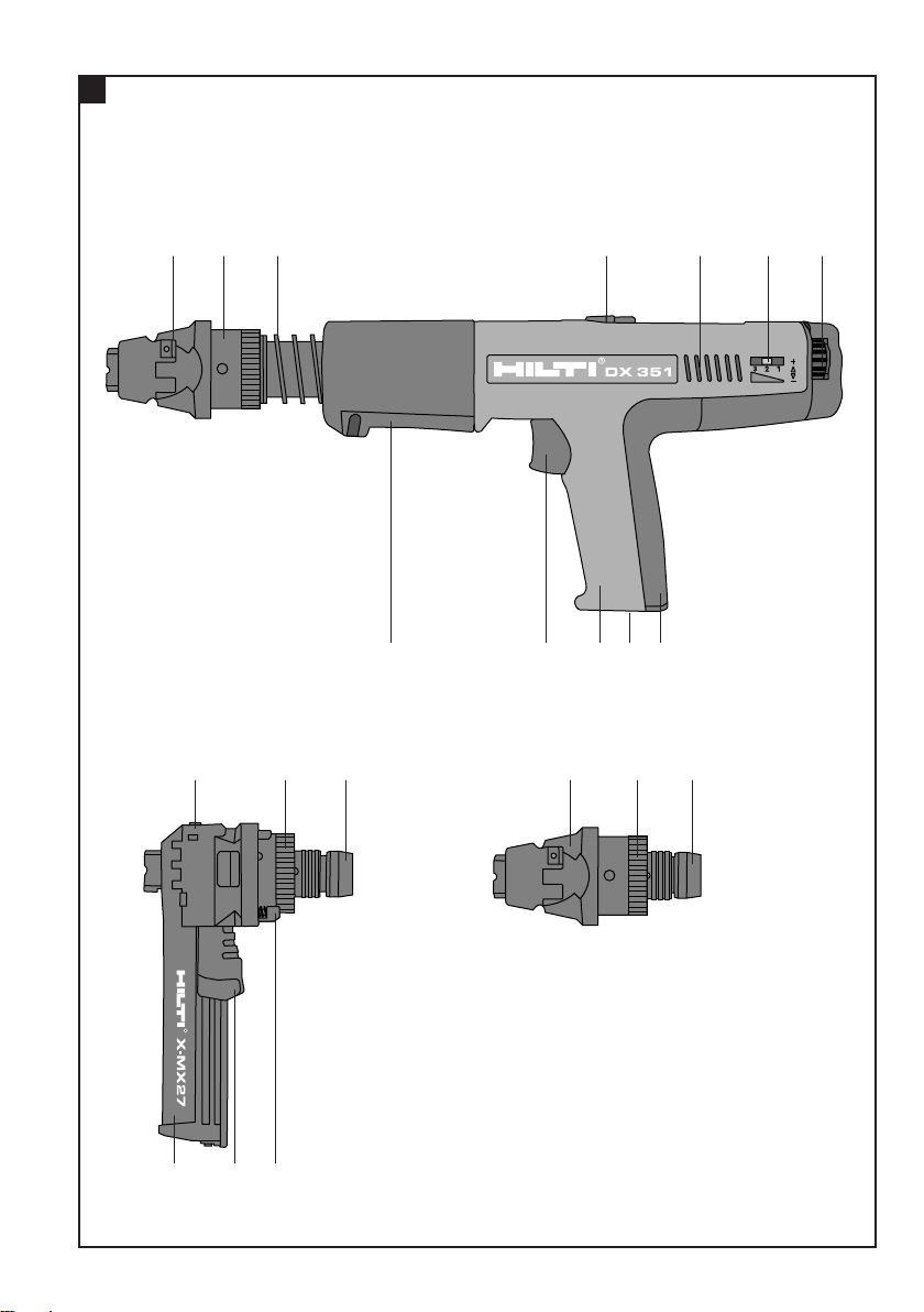
Description of main parts
쐃 Magazine housing
쐇 Nail pusher
쐋 Fastener feed delay device
쐏 Piston brake (part of fastener guide)
쐄 Threaded sleeve
쐂 Fastener guide
쐆 Piston return spring
쐊 Black housing
쐎 Trigger
쐅 Handle
쐈 Cartridge feeding
쐉 Cartridge ejection
씈 Grip
씉 Aeration slots
씊 Power regulation indicator
씋 Power regulation wheel
씌 Nail detector assy
ORIGINAL OPERATING INSTRUCTIONS
DX 351 powder-actuated tool
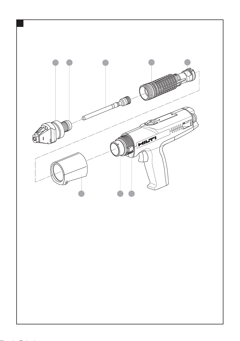
Tool components Item no.
쐃 Fastener guide*
쐇 Piston brake (part of fastener guide)
쐋 Piston*
쐏 Piston return spring 331010
쐄 Piston guide 331203
쐂 Black housing 331027
쐆 Piston stopper right 331158
쐊 Piston stopper left 331045
* These parts may be replaced by the user/operator
It is essential that the operating instructions are read before the tool is operated
for the first time.
Always keep these operating instructions
together with the tool.
Ensure that the operating instructions are
with the tool when it is given to other persons.
1. Safety precautions
1.1 Basic safety instructions
In addition to the safety precautions listed in the individual sections of these operating instructions, the
following points must be strictly observed at all times.
1.2 Only use Hilti cartridges or cartridges of equivalent quality
The use of cartridges of inferior quality in Hilti tools may
lead to build-up of unburned powder, which may explode and cause severe injuries to operators and bystanders. At a minimum, cartridges must either:
a) Be confirmed by their supplier to have been suc-
cessfully tested in accordance with EU standard EN
16264
NOTE:
● All Hilti cartridges for powder-actuated tools have
been tested successfully in accordance with EN 16264.
● The tests defined in the EN 16264 standard are system
tests carried out by the certification authority using
specific combinations of cartridges and tools.
The tool designation, the name of the certification authority and the system test number are printed on the
cartridge packaging.
or
b) Carry the CE conformity mark (mandatory in the EU
as of July 2013).
See packaging sample at:
www.hilti.com/dx-cartridges
1.3 Use as intended
The tool is designed for professional use in fastening
applications in construction where specially-designed
nails, threaded studs and composite fasteners are driven into concrete, steel and sand-lime block masonry.
Printed: 12.08.2013 | Doc-Nr: PUB / 5126242 / 000 / 01
Page 6
18
en
1.4 Improper use
● Manipulation or modification of the tool is not permissible.
● Do not operate the tool in an explosive or flammable
atmosphere, unless the tool is specially approved for
such use.
● Use only original Hilti fasteners, cartridges, accessories and spare parts or those of equivalent quality.
● Observe the information printed in the operating
instructions concerning operation, care and maintenance.
● Never point the tool at yourself or any bystander.
● Never press the muzzle of the tool against your hand
or other part of your body.
● Do not drive nails into excessively hard or brittle materials such as glass, marble, plastic, bronze, brass, copper, natural rock, insulation material, hollow brick, glazed
tile, thin-gauge sheet metal (< 4 mm), grey cast iron,
spheroidal cast iron and gas concrete.
1.5 Technology
● This tool is designed with the latest available technology.
● The tool and its ancillary equipment may present hazards when used incorrectly by untrained personnel or
not as directed.
1.6 Making the workplace safe
● Ensure that the workplace is well lit.
● Operate the tool only in well-ventilated working areas.
● The tool is for hand-held use only.
● Avoid unfavorable body positions. Work from a secure
stance and stay in balance at all times
● Keep other persons, children in particular, outside the
working area.
● Before using the tool, make sure that no one
is standing behind or below the point where fasteners
are to be driven.
● Keep the grip dry, clean and free from oil and grease.
1.7 General safety precautions
● Operate the tool only as directed and only when it is
in faultless condition.
● If a cartridge misfires or fails to ignite, proceed as follows:
1. Keep the tool pressed against the working surface for
30 seconds.
2. If the cartridge still fails to fire, withdraw the tool from
the working surface, taking care that it is not pointed
towards your body or bystanders.
3. Manually advance the cartridge strip one cartridge.
Use up the remaining cartridges on the strip. Remove
the used cartridge strip and dispose of it in such a
way that it can be neither reused nor misused.
● Never attempt to pry a cartridge from the magazine
strip or the tool.
● Keep the arms flexed when the tool is fired (do not
straighten the arms).
● Never leave the loaded tool unattended.
● Always unload the tool before beginning cleaning,
servicing or changing parts and before storage.
● Unused cartridges and tools not presently in use must
be stored in a place where they are not exposed to humidity or excessive heat. The tool should be transported
and stored in a toolbox that can be locked or secured to
prevent use by unauthorized persons.
1.8 Temperature
● Do not disassemble the tool while it is hot.
● Never exceed the recommended maximum fastener
driving rate (number of fastenings per hour). The tool
may otherwise overheat.
● Should the plastic cartridge strip begin to melt, stop
using the tool immediately and allow it to cool down.
1.9 Requirements to be met by users
● The tool is intended for professional use.
● The tool may be operated, serviced and repaired only
by authorised, trained personnel. This personnel must
be informed of any special hazards that may be encountered.
● Proceed carefully and do not use the tool if your full
attention is not on the job.
● Stop working with the tool if you feel any pain or dis-
comfort.
1.10 Personal protective equipment
● The operator and other persons in the immediate vicin-
ity must always wear approved eye protection, a hard
hat and suitable ear protection.
Printed: 12.08.2013 | Doc-Nr: PUB / 5126242 / 000 / 01
Page 7
19
en
3. Technical description
The tool is designed for professional use in fastening
applications where specially-designed nails, threaded
studs and compo site fasteners are driven into concrete,
steel and sand-lime block masonry.
The tool works on the well-proven piston principle and
is therefore not related to high-velocity tools. The piston principle provides an optimum of working and fastening safety. The tool works with cartridges of 6.8/11
caliber.
Piston return and cartridge transport is fully automatic.
This permits fastenings to be made very quickly and
economically with nails and threaded studs. The use of
a nail magazine (MX27 or MX32) greatly increases the
speed and convenience of fastening with the tool, above
all when making large numbers of identical fastenings
of all kinds.
As with all powder-actuated tools, the tool, magazine,
fastener program and cartridge program form a “technical unit”. This means that optimal fastening with this
system can only be achieved if the fasteners and cartridges are specially manufactured for it, or products of
equivalent quality, are used. The fastening and application recommendations given by Hilti are only applicable
if these conditions are observed.
The tool features 5-way safety – for the safety of the
operator and bystanders.
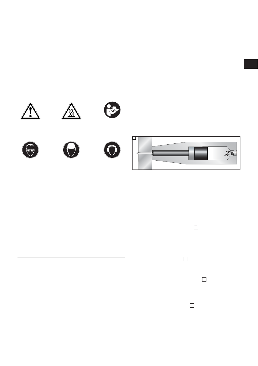
The piston principle
The energy from the propellant charge is transferred to
a piston, the accelerated mass of which drives the fastener
into the base material. As approximately 95 % of the
kinetic energy is absorbed by the piston, the fastener is
driven into the base material at much reduced velocity
(less than 100 m/sec.) in a controlled manner. The driving process ends when the piston reaches the end of
its travel. This makes dangerous through-shots virtually impossible when the tool is used correctly.
The drop-firing safety device is the result of coupling the firing mechanism with the cocking movement. This is designed to prevent the Hilti DX tool from
firing when it is dropped onto a hard surface, no matter at which angle the impact occurs.
The trigger safety device ensures that the cartridge
cannot be fired simply by pulling the trigger only. The
tool can be fired only when fully depressed.
The contact pressure safety device requires the tool
to be fully depressed with a significant force. The tool
can be fired only when pressed fully in this way.
In addition, all Hilti DX tools are equipped with an unintentional firing safety device . This prevents the tool
from firing if the trigger is pulled and the tool then pressed
against the work surface. The tool can be fired only when
it is first pressed 쩸 correctly and 쩹 the trigger then
pulled.
5
4
3
2
1
2. General information
2.1 Signal words and their meaning
WARNING: The word WARNING is used to draw atten-
tion to a potentially dangerous situation which could
lead to severe personal injury or death.
CAUTION: The word CAUTION is used to draw attention
to a potentially dangerous situation which could lead to
minor personal injury or damage to the equipment or
other property.
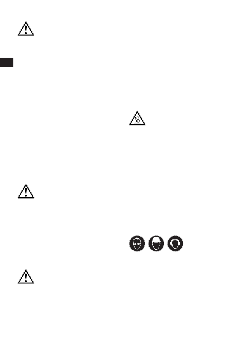
2.2 Pictograms
Warning signs
General
warning
Warning:
hot surface
Obligation signs
Wear eye
protection
Wear a
safety helmet
Wear ear
protection
Symbols
Read the opera-
tion instructions
before use
The numbers refer to the illustrations. The illustrations can be found on the fold-out cover pages. Keep
these pages open while you read the operating instructions.
In these operating instructions, the designation “the
tool” always refers to the DX 351 powder-actuated tool.
Location of identification data on the tool
The type designation and the serial number are printed
on the type plate on the tool. Make a note of this information in your operating instructions and always refer
to it when making an enquiry to your Hilti representative or service department.
Type: DX351 Serial no.:
Printed: 12.08.2013 | Doc-Nr: PUB / 5126242 / 000 / 01
Page 8

20
en
4. Accessories, cartridges and fasteners
Cartridges
Ordering designation Colour code Power level
6.8/11M white White Extra low
6.8/11M green Green Light
6.8/11M yellow Yellow Medium
6.8/11M red Red Heavy
Prevention of misuse:
– When the piston tip is worn or damaged (see 7.), never try to grind the tip in order to re-use the piston. This may
cause serious damage to the tool and will adversely affect fastening quality.
– Please refer to the table below for the right fastener guide/piston/fastener combination. Use of the wrong com-
bination may result in damage to the tool.
2
4
3
5
2
1
Printed: 12.08.2013 | Doc-Nr: PUB / 5126242 / 000 / 01
Page 9

21
en
Fastener guide Piston type Elements
Magazine X-MX27 Magazine X-MX32 X-P8S-351 X-MX27:
X-C20-27MX
X-U20-27
Length: 160 mm X-U15MXSP
Weight: 93 g
X-MX32:
X-C20-32MX
X-U20-32MX
X-U15MXSP
Standard fastener guide X-FG8S-351 X-P8S-351 X-C22-47P8
X-C20THP
X-C22-27P8TH
Length: 160 mm X-C27-C52P8S36
Weight: 93 g X-HS M6/8/10 XU19-32
ME fastener guide X-FG8ME-351 X-HS W6/8/10, XU19-27
X-FB-C27
X-FB-U22
X-RH
1
/4-U27P8
X-M6, X-EM6 / X-F7, X-EF7*
* (up to max. 47 mm/1.85″)
X-M8, X-EM8
Narrow access fastener guide X-FG8L-351 X-P8L-351 X-CF20-47P8
X-C20-47P8
X-U16-47P8
Length: 182 mm X-CC U16-27
Weight: 103 g X-CC C27-32
X-HS M6/8/10 U19-32
X-HS W6/10 U19-27
5. Technical data
DX 351
Weight: 2.2 kg (4.8 lb)
2.4 kg (5.3 lb) with magazine
Tool length: 404 mm (15.9″)
Nail length: Max. 47 mm (1.85″)
Cartridge: 6.8/11 M (27 cal. short) white, green, yellow, red
Compression stroke: 59 mm (2.3″)
Compression force with magazine: 130 N
Compression force with standard fastener guide: 100 N
4 cartridge power levels, click-stop regulation thumbwheel
Nail magazine MX 27 MX 32
Weight : 0.16 kg (0.35 lb) 0.16 kg (0.35 lb)
Nail length: 27 mm (1″) 32 mm (11/4″)
Magazine capacity: 10 nails 10 nails
Recommended max. fastener driving frequency: 700/h with white, green or yellow cartridges
500/h with red cartridges
Right of technical changes reserved
;0;
Printed: 12.08.2013 | Doc-Nr: PUB / 5126242 / 000 / 01
Page 10

22
en
6. Operation
CAUTION
■ The nail or stud is driven by a cartridge being fired.
■ Excessive noise may damage the
hearing.
■ Wear ear protection (users and
bystanders).
WARNING
■ The tool could be made ready to
fire if pressed against a part of
the body (e.g. hand)..
■ This could cause a nail or piston
to be driven into a part of the body.
■ Never press the muzzle of the tool
against parts of the body.
WARNING
■ Under certain circumstances, the
tool could be made ready to fire
by pulling back the magazine, fastener guide or the fastener by
hand.
■ When in the “ready to fire” state,
a fastener or the piston could be
driven into a part of the body.
■ For this reason, never pull back
the magazine, fastener guide or
fastener by hand.
WARNING
■ The base material may splinter
when a fastener is driven or fragments of the cartridge strip may
fly off.
■ Flying fragments may injure parts
of the body or the eyes.
■ Wear approved eye protection
and a hard hat (users and by standers).
Guidelines for optimum fastening quality
NOTE
These application recommendations must always be
observed. For more specific information, refer to the
Hilti Fastening Technology Manual, which is available
from your local Hilti organisation.
Minimum requirements
Fastening on steel
A = min. edge distance = 15 mm (
5
/8")
B = min. spacing = 20 mm (
3
/4")
C = min. base material thickness = 4 mm (
5
/32")
Fastening on concrete
A = min. edge distance = 70 mm (2
3
/4")
B = min. spacing = 80 mm (3
1
/8")
C = min. base material thickness = 100 mm (4")
Nail lengths
(These are only examples, find specific information in
the Hilti Fastening Technology Manual
Fastening on concrete
Penetration depth (ET): 22–27 mm, (
7
/8"–1")
Fastening on steel:
Penetration depth (ET): 12 ± 2 mm, (
1
/2" ± 1/16")
ET
BA
C
BA
ET C
Printed: 12.08.2013 | Doc-Nr: PUB / 5126242 / 000 / 01
ET
Page 11

23
en
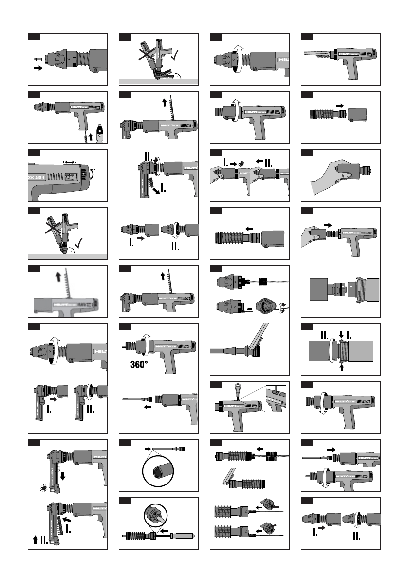
쎱쎱
6.1 Loading the single-fastener tool
Insert the fastener flat end (head) first until the washer
is held in the tool.
쎱쎱
6.2 Inserting the cartridge strip
Load the cartridge strip narrow end first by inserting it
into the bottom of the toolgrip until flush. If the strip has
been partly used, pull it through until a live cartridge is
in the chamber.
쎱쎱
6.3 Power regulation
Adjust the driving power by turning the regulating wheel.
1= minimum power
2= medium power
3= maximum power
Select the cartridge power level and power regulation
setting to suit the application. If you have no previous
experience of this application, always begin with the
lowest power level.
쎱쎱
6.4 Using the single-fastener tool
When fastening, position the tool perpendicular to the
work surface, press down and then pull the trigger.
WARNING
–
Re-use of fasteners:
If the first attempt to drive a fastener fails, so not use
or redrive the same fastener a second time.
–
Do not drive fasteners into holes:
Driving fasteners into existing holes is not permissible unless specifically authorized by Hilti.
–
Fastener driving rate:
Do not exceed the maximum fastener driving rate.
쎱쎱
6.5
Pull the cartridge strip out of the tool.
쎱쎱
6.6 Fitting the magazine
1. Unscrew the single fastening fastener guide, threaded sleeve and pull the fastener guide out.
2.Press the nail magazine onto the piston guide, then
screw the threaded sleeve on clockwise until it engages.
쎱쎱
6.7 Loading the magazine tool
1. Unscrew the single fastening fastener guide, threaded sleeve and pull the fastener guide out.
2. Press the nail magazine onto the piston guide, then
screw the threaded sleeve on clockwise until it engages.
쎱쎱
6.8 Using the magazine tool
When fastening , position the tool perpendicular to the
work surface, press down and then pull the trigger.
Note:
If the nail magazine is empty, the tool cannot be fired.
쎱쎱
6.9 Conversion to single-fastening tool
(changing the equipment)
1. Pull the cartridge strip out of the tool.
2. Open the magazine by pulling the nail pusher down
until it locks, then take out the nail strip. Unscrew the
magazine threaded sleeve.
3. Press the single fastener guide onto the piston guide,
then screw the threaded sleeve on until it engages.
7. Service (changing the piston and
piston brake)
쎱쎱
7.1 Check that the tool is not hot.
쎱쎱
7.2 Remove the cartridge strip from the tool. Unscrew
the fastener guide or magazine.
쎱쎱
7.3 Turn the black housing one whole revolution (360°
counter clockwise). This will release the piston stoppers
so you can remove the piston from the tool.
쎱쎱
7.4 Typical wear of piston.
Check if piston is chipped or damaged. Replace if significant chipping or damage has occurred.
쎱쎱
7.5 If the piston sticks in the piston guide, the entire
piston guide unit must be removed (see section «Care
and maintenance»). Push out the piston through the
cartridge chamber.
Note:
Do not grind the piston. If the piston is made shorter
the tool will be damaged.
8. Care and maintenance
When this type of tool is used under normal operating
conditions, dirt and residues build up inside the tool
and functionally relevant parts are also subject to wear.
Regular inspections and maintenance are thus essential in order to achieve reliable operation. We recommend that the tool is cleaned and the piston and piston
brake are checked at least weekly when the tool is subjected to intensive use, and at the latest after driving
8,000 fasteners.
Care of the tool
The outer casing of the tool is manufactured from impactresistant plastic. The grip comprises a synthetic rubber
section. The ventilation slots must be unobstructed and
kept clean at all times. Do not permit foreign objects to
enter the interior of the tool. Use a slightly damp cloth
to clean the outside of the tool at regular intervals. Do
not use a spray or steam-cleaning system for cleaning.
Maintenance
Check all external parts of the tool for damage at regular intervals and check that all controls operate properly. Do not operate the tool when parts are damaged or
Printed: 12.08.2013 | Doc-Nr: PUB / 5126242 / 000 / 01
Page 12

24
en
when the controls do not operate properly. If necessary,
have the tool repaired at a Hilti service centre.
Servicing the tool
The tool should be serviced if:
1. Cartridges misfire
2. Fastener driving power is inconsistent
3. If you notice that:
● contact pressure increases,
● trigger force increases,
● power regulation is difficult to adjust (stiff),
● the cartridge strip is difficult to remove.
CAUTION while cleaning the tool:
● Never use grease for maintenance /lubrication of tool
parts. This may strongly affect the functionality of the
tool. Use only Hilti spray or such of equivalent quality.
● Dirt from DX tool contains substances that could be
endangering your health.
– Do not breath in the dust from cleaning
– Keep dust away from food
– Wash your hands after cleaning the tool
9. Assembly
쎱쎱
9.1 Put the black housing onto the piston guide.
쎱쎱
9.2 Pull up the black housing against the spring and
hold it with your hand.
쎱쎱
9.3 Insert the complete unit so that the marks on the
piston guide and the marks on the metal housing are in
alignment.
쎱쎱
9.4 Push in the stoppers when the piston guide is in
far enough, so that the stoppers fit into the sleeve on
the side of the piston guide openings.
쎱쎱
9.5 Release the black housing and screw it on one or
two turns.
쎱쎱
9.6 Insert the piston all the way back (the piston can
be inserted anytime before the last whole turn) and finish screwing on the black housing until it engages.
쎱쎱
9.7 Press the single fastener guide or magazine into
the piston guide, then screw the threaded sleeve on until
it engages.
Warning: The tool must be unloaded before carrying
out care and maintenance.
쎱쎱
8.1 Remove fastener guide or magazine
쎱쎱
8.2 Service
Unscrew the black housing counter clockwise fully.
쎱쎱
8.3 Push back the piston guide with the palm of the
hand to release the piston stoppers and then remove
the complete unit.
쎱쎱
8.4 Remove the black housing from the piston guide.
쎱쎱
8.5 Clean the fastener guide or magazine and the pis-
ton.
쎱쎱
8.6 Clean the cartridge transport.
쎱쎱
8.7 Clean the piston guide inside and outside (back-
side of the piston guide and the spring area.) and lubricate it on the outside.
Clean in the cartridge chamber and the power regulation hole at the end-face of the piston guide..
쎱쎱
8.8 Clean the inside of the housing. Slightly lubricate
the inside.
CAUTION
■ The tool can get hot while operating.
■ You could burn your hands.
■ Do not disassemble the tool while
it is hot. Let the tool cool down.
Printed: 12.08.2013 | Doc-Nr: PUB / 5126242 / 000 / 01
Page 13

Cartridge strip melts
Cartridge cannot be fired
25
en
Cartridge strip cannot be
removed
10. Troubleshooting
Cartridge not transported
Fault
Cause
■ Damaged cartridge strip
■ Carbon build up
■ Tool damaged
■ Tool overheated because of high
setting rate
■ Tool damaged
WARNING
Never attempt to pry a cartridge
from the magazine strip or tool.
■ Bad cartridge
■ Carbon build-up
WARNING
Never attempt to pry a cartridge
from the magazine strip or the tool.
Possible remedies
■ Change cartridge strip
■ Clean the cartridge strip guide-
way (see 8.6)
If the problem persists:
■ Contact Hilti Repair Centre
■ Let the tool cool down and then
carefully try to remove the
cartridge strip
If not possible:
■ Contact Hilti Repair Centre
■ Manually advance the cartridge
strip one cartridge
■ If the problem occurs more
often:
Clean the tool (see 8.1–8.8)
If the problem persists:
■ Contact Hilti Repair Centre
■ Tool is compressed too long
while fastening.
■ Fastening frequency is too high
■ Compress the tool only while
fastening.
■ Remove the cartridge strip
■ Disassemble the tool (see
7.1–7.3)
for fast cooling and to avoid
possible damage
■ Do not exceed the recommended
fastener driving rate
If the tool cannot be disassembled:
■ Contact Hilti Repair Centre
Printed: 12.08.2013 | Doc-Nr: PUB / 5126242 / 000 / 01
Page 14

Varying depths of penetration
26
en
Cartridge falls out of the
cartridge strip
The operator notices:
– increased contact pressure
– increased trigger force
– power regulation stiff to adjust
– cartridge strip is difficult to
remove
■ Fastening frequency is too high
WARNING
Never attempt to pry a cartridge
from the magazine strip or tool.
■ Carbon build-up
■ Immediately discontinue using
the tool and let it cool down
■ Remove cartridge strip
■ Let the tool cool down
■ Clean the tool and remove loose
cartridge
If it is impossible to disassemble
the tool:
■ Contact Hilti Repair Centre
■ Clean the tool
(see 8.1–8.8)
■ Check that the correct cartridges
are used (see 1.2) and that they
are in faultless condition.
■ The tool is dirty (carbon buildup)
■ Clean the tool
(see 8.1–8.8)
■ Check piston, replace if necessary
Fault
Cause Possible remedies
Trigger cannot be pulled
■ Tool not fully compressed
■ Safety mechanism activated
because:
– Magazine not loaded
– Plastic debris inside the
magazine
– Incorrect piston position
– Nail incorrectly positioned in
magazine
■ Release the tool and fully compress it again
■ Load fastener strip
■ Open magazine, remove fastener
strip and plastic debris
If problem persists:
■ Clean the tool (see 8.1–8.8)
■ Check to ensure that the tool is
assembled correctly
Printed: 12.08.2013 | Doc-Nr: PUB / 5126242 / 000 / 01
Page 15

Fastener does not penetrate
deeply enough
27
en
Piston stuck in magazine fastener
guide
■ Piston damaged
■ Plastic debris inside the
magazine
■ Excess power when fastening on
steel
■ Tool fired with high power
without fastener in place
■ Unscrew the magazine
■ Unscrew the black part of the
housing
■ Check piston and replace if
necessary (see 7.1–7.5)
■ Open magazine, remove fastener
strip and plastic debris
■ Reduce the power setting
■ Avoid firing the tool without a
fastener in place
Fault
Cause Possible remedies
■ Fastener too short
■ Driving power too high
■ Fastener too long
■ Driving power too low
■ Use longer fastener
■ Reduce power setting
■ Use lighter cartridge
■ Use shorter fastener
if permissible
■ Increase power setting
■ Use heavier cartridge
■ Use a more powerful system
such as the DX 460
Nail bends
■ Hard and/or large aggregate in
concrete
■ Rebar close to surface of
concrete
■ Hard surface (steel)
■ Use shorter fastener if permiss-
able
■ Use a nail with a higher application limit
■ Change to single fasteners
■ Use an alternative system (spall
stop or DX-Kwik)
Fastener penetrates too deeply
Printed: 12.08.2013 | Doc-Nr: PUB / 5126242 / 000 / 01
Page 16

Base material is spalling
Nail breaks
Nail does not
penetrate surface
Wasted (unused) cartridges
28
en
Fault
Cause Possible remedies
■ High strength concrete
■ Hard and/or large aggregate in
concrete
■ Old concrete
■ Adjust the power setting
■ Use an alternative system
(DX460 with spall stop or DXKwik)
■ Driving power too low
■ Application limit exceeded
(very hard surface)
■ Unsuitable system
■ Use a higher power setting or
heavier cartridge
■ Use nail with higher application
limits
■ Switch to more powerful system
e.g. DX 460
■ Driving power too low
■ Application limit exceeded
(very hard surface)
■ Try higher power setting or
heavier cartridge
■ Use a shorter nail if permissible
■ Use nail with higher application
limits
■ Switch to more powerful system
e.g. DX 460
■ The tool is not pressed fully
against the work surface
■ Press the tool fully against the
work surface before pulling the
trigger
Printed: 12.08.2013 | Doc-Nr: PUB / 5126242 / 000 / 01
Page 17

29
en
Fault
Cause Possible remedies
■ The piston is damaged
■ Remains of plastic strip in maga-
zine
■ Driving power too high when driving into steel
■ Firing the tool with high power
without a fastener in place
■ The tool is dirty (carbon buildup)
■ Unscrew the magazine
■ Unscrew the black housing
■ Check the piston and replace if
necessary (see 7.1–7.5)
■ Open the magazine and remove
the nail strip and any plastic
remains
■ Reduce driving power
■ Avoid firing without a fastener in
place
■ Clean the tool (see 8.1–8.8)
Nail jams in the magazine
■ 2 nails are jammed together in
the magazine
■ Insert the tip of a screwdriver
through the furthest forward slot
in the magazine and push the
nails out
Piston guide sticks
Printed: 12.08.2013 | Doc-Nr: PUB / 5126242 / 000 / 01
Page 18

en
30
12. Manufacturer’s warranty – DX tools
Hilti warrants that the tool supplied is free of defects in
material and workmanship. This warranty is valid so
long as the tool is operated and handled correctly, cleaned
and serviced properly and in accordance with the Hilti
Operating Instructions, and the technical system is maintained. This means that only original Hilti consumables,
components and spare parts, or other products of equivalent quality, may be used in the tool.
This warranty provides the free-of-charge repair or
replacement of defective parts only over the entire lifespan of the tool. Parts requiring repair or replacement as
a result of normal wear and tear are not covered by this
warranty.
Additional claims are excluded, unless stringent nation-
11. Disposal
Most of the materials from which Hilti power actuated tools are manufactured can be recycled. The materials must
be correctly separated before they can be recycled. In many countries, Hilti has already made arrangements for
taking back your old powder actuated tools for recycling. Please ask your Hilti customer service department or
Hilti sales representative for further information.
Should you wish to return the power actuated tool yourself to a disposal facility for recycling, proceed as follows:
Dismantle the tools as far as possible without the need for special tools.
Separate the individual parts as follows:
Part / assembly Main material Recycling
Toolbox Plastic Plastics recycling
Outer casing Plastic / synthetic rubber Plastics recycling
Screws, small parts Steel Scrap metal
Used cartridge strip Plastic / steel According to local regulations
al rules prohibit such exclusion. In particular, Hilti is
not obligated for direct, indirect, incidental or consequential damages, losses or expenses in connection
with, or by reason of, the use of, or inability to use the
tool for any purpose. Implied warranties of merchantability or fitness for a particular purpose are
specifically excluded.
For repair or replacement, send tool or related parts
immediately upon discovery of the defect to the address
of the local Hilti marketing organization provided.
This constitutes Hilti's entire obligation with regard to
warranty and supersedes all prior or contemporaneous
comments and oral or written agreements concerning
warranties.
13. EC declaration of conformity (original)
Designation: Powder-actuated tool
Type: DX 351
Year of design: 2000
We declare, on our sole responsibility, that this product
complies with the following directives and standards:
2006/42/EC, 2011/65/EU.
Hilti Corporation, Feldkircherstrasse 100,
FL-9494 Schaan
Norbert Wohlwend Tassilo Deinzer
Head of Quality & Processes Management Head BU Measuring Systems
BU Direct Fastening BU Measuring Systems
08/2012 08/2012
Technical documentation filed at:
Hilti Entwicklungsgesellschaft mbH
Zulassung Elektrowerkzeuge
Hiltistrasse 6
86916 Kaufering
Deutschland
Printed: 12.08.2013 | Doc-Nr: PUB / 5126242 / 000 / 01
Page 19

31
en
14. CIP approval mark
The following applies to C.I.P. member states outside
the EU and EFTA judicial area:
The Hilti DX 351 has been system and type tested. As a
result, the tool bears the square approval mark showing
approval number S 809. Hilti thus guarantees compliance with the approved type.
Unacceptable defects or deficiencies, etc. determined
during use of the tool must be reported to the person
responsible at the approval authority (PTB, Braunschweig)) and to the Office of the Permanent International Commission (C.I.P.) (Permanent Internationial
Commission, Avenue de la Renaissance 30, B-1000
Brussels, Belgium).
15. Health and safety of the user
Noise information
The following table provides noise measurement information:
Powder-actuated tool
Type: DX 351
Model: Serial production
Caliber: 6.8/11 red
Power setting: max
Application: Fastening 2 mm sheet steel to concrete (C40)
using X-U 27/32P8 nail
Declared measured values of noise characteristics according to 2006/42/EC Machinery Directive in
conjunction with E DIN EN 15895
Noise (power) level: L
WA, 1s
1
107 dB(A)
Emission noise-pressure level in the work station: L
pA, 1s
2
101 dB(A)
Peak sound pressure emission level: L
pC, peak
3
135 dB(C)
Operation and set-up conditions:
Set-up and operation of the pin driver in accordance with E DIN EN 15895-1 in the semi-anechoic test room of
Muller-BBM GmbH. The ambient conditions in the test room conform to DIN EN ISO 3745.
Testing procedure:
Enveloping surface method in anechoic room on reflective surface area in accordance with E DIN EN 15895, DIN
EN ISO 3745 and DIN EN ISO 11201.
NOTE: The noise emissions measured and the associated measurement uncertainty represent the upper limit for
the noise values to be expected during the measurements.
Variations in operating conditions may cause deviations from these emission values.
1
± 2 dB (A)
2
± 2 dB (A)
3
± 2 dB (C)
Vibration
The declared total vibration value according to 2006/42/EC does not exceed 2.5 m/s2.
Further information regarding the health and safety of the user can be found at the Hilti web site: www.hilti.com/hse
Printed: 12.08.2013 | Doc-Nr: PUB / 5126242 / 000 / 01
Page 20

32
Printed: 12.08.2013 | Doc-Nr: PUB / 5126242 / 000 / 01
Page 21

*332581*
332581
Hilti Corporation
LI-9494 Schaan
Tel.: +423/ 234 2111
Fax:+423 /23429 65
www.hilti.com
Hilti = registered trademark of Hilti Corp., Schaan
W 2375 | 0713 | 10-Pos. 2 | 1
Printed in Germany © 2013
Right of technical and programme changes reserved S. E. & O
.
332581 / A3
Printed: 12.08.2013 | Doc-Nr: PUB / 5126242 / 000 / 01
 Loading...