

Hilti DSH 700, DSH 900 Original Operating Instructions

DSH 700/
DSH 900
*288291*
288291
HiltiCorporation
LI-9494Schaan
Tel.:+423/ 2342111
Fax:+423/ 2342965
www.hilti.com
Hilti= registeredtrademarkofHilti Corp.,Schaan W 35030310 00-Pos.2 1 Printed inItaly © 2010
Rightof technicalandprogrammechanges reserved S.E. &O.
288291/ D
Operatinginstructions en
Brugsanvisning da
Bruksanvisning sv
Bruksanvisning no
Käyttöohje fi
Instrukcjaobsługi pl
Инструкцияпо зксплуатации ru
1/3
1/3
1/3
15
1
3/8
6
5
2/6
4/7
16
17
15
4
5
0.5mm
2/8
14
6
7
5
1/12
2
10
8
4
4
3
12
2
3
13
00_Cover_DSH700_900_P2.qxd:00_Cover_DSH700_900_P1.qxd 25.3.2010 15:47 Uhr Seite 1
19
2
"≠
+# +] +[
"Ç
+|
5 +}
+≠ 7 6
+±
4 +{ "#
+“ "“
"[
+Ç
3 "±
8
1
ꨍ
ꨏ
ꨔ
ꨑ
ꨎ
ꨐ
ꨕ
ꨒ
ꨓ
2
1/8
1/8
4
2/7/9
3
3
1/15
14
2/4
5/13
4
6
3/10
8
7
9
11
4
1
2
5
1
5
7
3
2/4
3
6
6
6
2
5
6
3
4
8
9/10
8
7
3/4
3/4
3/4
3/4
11
1/5
1/5
2
10
8 9
00_Cover_DSH700_900_P2.qxd:00_Cover_DSH700_900_P1.qxd 25.3.2010 15:47 Uhr Seite 5

ORIGINAL OPERATING INSTRUCTIONS
DSH 700/ DSH 900 cut-off saw
It is essential that the operating instructions
are read before the machine is operated for
the first time.
Always keep these operating instructions
together with the machine.
Ensure that the operating instructions are
with the machine when it is given to other
persons.
Contents Page
1. General information 2
2. Description 3
3. Accessories 4
4. Technical data 5
5. Safety instructions 7
6. Before use 10
7. Operation 14
8. Care and maintenance 15
9. Troubleshooting 19
10. Disposal 21
11. Manufacturer’s warranty 21
12. EC declaration of conformity 22
1 These numbers refer to the corresponding illustrations. The illustrations can be found on the fold-out
cover pages. Keep these pages open while studying
the operating instructions.
In these operating instructions, the designation “the
machine” always refers to the DSH 700 or DSH 900
hand-held gas saw.
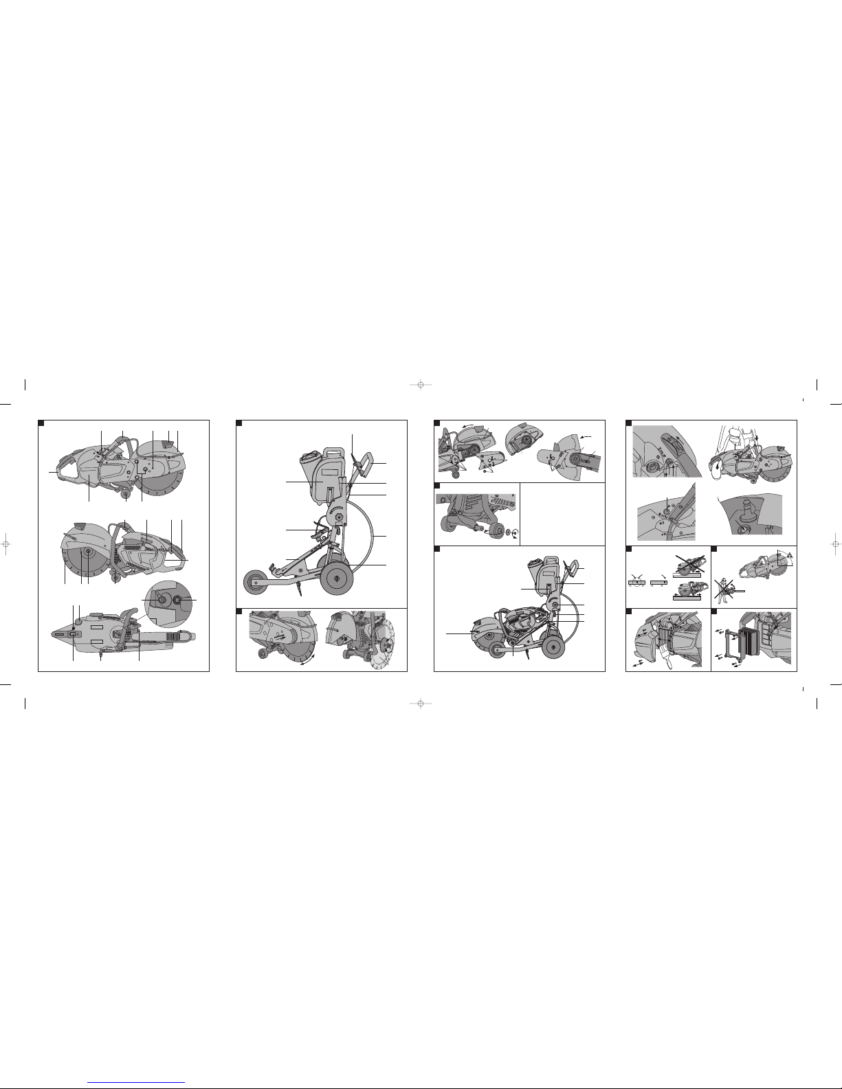
Parts, operating controls and indicators (DSH 700 /
DSH 900) 1
@
Forward grip
;
Rear grip
=
Guide wheels
%
Start/stop switch
&
Choke lever / half-throttle lock
(
Throttle safety grip
)
Throttle trigger
+
Decompression valve
§
Fuel pump
/
Starter handle
:
Cutting disc
·
Clamping screw
$
Hole for locking pin for changing cutting discs
£
Clamping flange
|
Guard (hood)
¡
Disc guard adjustment grip
Q
Water valve
W
Water connection
E
Fuel tank cap
R
Air filter cover
T
Belt tensioner
Z
Exhaust / muffler
U
Spark filter
I
Spark plug connector
O
Type identification plate
DSH-FSC saw carriage 2
@
Grip
;
Throttle trigger
=
Cutting depth adjustment
%
Hold-down device
&
Water tank
(
Water connection
)
Axial adjustment
+
Throttle cable
§
Machine cradle
en
1

5100
r
p
m
m
a
x.
1. General information
1.1 Safety notices and their meaning
DANGER
Draws attention to imminent danger that could lead
to serious bodily injury or fatality.
WARNING
Draws attention to a potentially dangerous situation
that could lead to serious personal injury or fatality.
CAUTION
Draws attention to a potentially dangerous situation
that could lead to slight personal injury or damage to
the equipment or other property.
NOTE
Draws attention to an instruction or other useful
information.
1.2 Explanation of the pictograms and other
information
Prohibition signs
Transport by
crane is not
permissible.
Warning signs
General
warning
Warning: hot
surface
Warning:
Flying sparks
present a fire
risk.
Warning: Risk
of kickback.
Warning:
Don’t inhale
toxic vapors or
exhaust
fumes.
Minimum
permissible
speed rating of
the cutting
discs used
Obligation signs
Wear
protective
gloves.
Wear safety
shoes.
Wear ear
protection, eye
protection,
respiratory
protection and
a hard hat.
Don’t use
toothed
cutting discs.
Don’t use
damaged
cutting discs.
Smoking and
naked flames
prohibited.
Symbols
Read the
operating
instructions
before use.
Motor stop
system
Fuel pump
Location of identification data on the machine
The type designation and serial number can be found
on the type identification plate on the machine. Make
a note of this data in your operating instructions and
always refer to it when making an enquiry to your
Hilti representative or service department.
Type:
Generation: 01
Serial no.:
en
2

2. Description
2.1 Use of the product as directed
The machine is intended for hand-held or walk-behind
use for dry or wet cutting of asphalt and mineral
or metallic construction materials using abrasive or
diamond cutting discs.
To reduce the amount of dust produced when cutting,
we recommend use of the wet cutting method.
The working environment may be as follows: construction site, workshop, renovation, conversion or
new construction.
To avoid the risk of injury, use only genuine Hilti
accessories and cutting tools.
Observe the safety rules and operating instructions
for the accessories used.
Working on materials hazardous to the health (e.g.
asbestos) is not permissible.
Observe the information printed in the operating instructions concerning operation, care and maintenance.
Nationally applicable industrial safety regulations
must be observed.
The machine is designed for professional use and
may be operated, serviced and maintained only by
trained, authorized personnel. This personnel must
be informed of any special hazards that may be encountered. The machine and its ancillary equipment
may present hazards when used incorrectly by untrained personnel or when used not as directed.
Take the influences of the surrounding area into
account. Do not use the power tool or appliance
where there is a risk of fire or explosion.
Modification of the machine or tampering with its
parts is not permissible.
Don’t work in closed, poorly ventilated rooms.
2.2 Items supplied as standard
1 Machine
1 DSH tool set
1 Operating instructions
1 DSH consumables kit
2.3 Abrasive cutting discs for hand-guided
gasoline-powered cut-off saws
Abrasive cutting discs for gasoline-powered cut-off
saws are composed of synthetic resin-bonded ab-
rasive granulate. These cutting discs feature fabric
or fiber reinforcement which improves their strength,
toughness and breakage resistance.
NOTE
Abrasive cutting discs for gasoline-powered cut-off
saws are used mainly for cutting ferrous and nonferrous metals.
NOTE
Various grit types such as aluminum oxide, silicon
carbide, zirconium, etc., with a different bonding
material (matrix) or matrix hardness, are available
depending on the construction material to be cut.
2.4 Diamond cutting discs for hand-guided
gasoline-powered cut-off saws
Diamond cutting discs for gasoline-powered cut-off
saws consist of a steel core (disc) with diamond
segments (metallically bonded industrial diamonds).
NOTE
Segmented diamond cutting discs or those with a
continuous cutting face are mainly used for cutting
asphalt and mineral construction materials.
2.5 Cutting disc specifications
Diamond cutting discs in compliancewith the requirements of EN 13236 are to be used with the machine.
Synthetic resin-bonded fiber-reinforced cutting discs
in compliance with EN 12413 (straight, not offset,
type 41) may also be used with this machine for
working on metals. The mounting instructions and
instructions for use issued by the disc manufacturer
must also be observed.
2.6 Recommendations for use
We recommend that the workpiece is not cut through
in a single operation. Advance to the required depth
of cut by making several to-and-fro movements.
To avoid damaging the diamond cutting disc when
dry cutting, lift the blade out of the cut for approx. 10
seconds every 30 to 60 seconds while the machine is
still running.
To reduce the amount of dust produced when cutting,
we recommend use of the wet cutting method.
en
3

3. Accessories
Accessories for the DSH 700 and DSH 900
Diamond cutting disc
000000, See main catalog.
Abrasive cutting disc
000000, See main catalog.
Two-stroke oil
DSH (1 L)
365827
Water supply unit DWP 10 365595
Saw carriage DSH-FSC
431364
Hard hat 267736
Protective glasses
I-VO B05 PS clear
285780
Container DSH
365828
Consumables kit DSH
365602
Consumables and wearing parts for the DSH 700
Air filter DSH
261990
Cord (5 pcs) DSH
412230
Starter DSH 700
359425
Drive belt
DSH 12/14"
359476
Filter element
DSH
412228
Spark plug DSH
412237
Tool set
DSH
359648
Cylinder set DSH 700
412245
Fastening screw assy.
DSH
412261
Flange (2)
DSH
412257
Centering ring 20 mm / 1" DSH
412264
Consumables and wearing parts for the DSH 900
Air filter DSH
261990
Cord (5 pcs) DSH
412230
Starter DSH 900
359427
Drive belt
DSH 12/14"
359476
Drive belt
DSH 16"
359477
Filter element
DSH
412228
Spark plug DSH
412237
Tool set
DSH
359648
Cylinder set DSH 900
412384
Fastening screw assy.
DSH
412261
Flange (2)
DSH
412257
Centering ring 20 mm / 1" DSH
412264
en
4

4. Technical data
Right of technical changes reserved.
NOTE
The vibration emission level given in this information sheet has been measured in accordance with a
standardised test given in EN 19432 and may be used to compare gasoline-powered cut-off saws with
each other. It may be used for a preliminary assessment of exposure. The declared vibration emission level
represents the main applications of the machine. However if the machine is used for different applications, with
different accessories or poorly maintained, the vibration emission may differ. This may significantly increase
the exposure level over the total working period. Note that excessive exposure of the hand-arm system to
vibration may cause blood circulation disorders (e.g. Raynaud’s disease). An estimation of the level of exposure
to vibration should also take into account the times when the machine is switched off or when it is running
but not actually doing the job. This may significantly reduce the exposure level over the total working period.
Identify additional safety measures to protect the operator from the effects of vibration such as: maintain the
machine and the accessories, keep the hands warm, organisation of work patterns.
Machine
DSH 700 30 cm
/ 12"
DSH 700 35 cm
/ 14"
DSH 900 35 cm
/ 14"
DSH 900 40 cm
/ 16"
Motor type Two-stroke /
single-cylinder /
air-cooled
Two-stroke /
single-cylinder /
air-cooled
Two-stroke /
single-cylinder /
air-cooled
Two-stroke /
single-cylinder /
air-cooled
Cubic capacity
68.7 cm³ 68.7 cm³ 87 cm³ 87 cm³
Weight without
cutting disc, tank
empty
11.3 kg 11.5 kg 11.7 kg 11.9 kg
Weight with saw
carriage, without
cutting disc, tank
empty
42.3 kg 42.5 kg 42.7 kg 42.9 kg
Power rating 3.7 kW 3.7 kW 4.5 kW 4.5 kW
Maximum arbor
speed
5,100/min 5,100/min 5,100/min 4,700/min
Engine speed 10,000±200/min 10,000±200/min 10,000±200/min 10,000±200/min
No-load speed 2,500…3,000/min 2,500…3,000/min 2,500…3,000/min 2,500…3,000/min
Dimensions with
cutting disc (L x
W x H) in mm
783 X 261 X 434 808 X 261 X 434 808 X 261 X 434 856 X 261 X 466
Ignition (type) Electronically-
controlled ignition
timing
Electronicallycontrolled ignition
timing
Electronicallycontrolled ignition
timing
Electronicallycontrolled ignition
timing
Electrode gap 0.5 mm 0.5 mm 0.5 mm 0.5 mm
Spark plug Manufacturer: NGK
Type: CMR7A-5
Manufacturer: NGK
Type: CMR7A-5
Manufacturer: NGK
Type: CMR7A-5
Manufacturer: NGK
Type: CMR7A-5
Carburetor Manufacturer: Wal-
bro
Model: WT
Type: 895
Manufacturer: Walbro
Model: WT
Type: 895
Manufacturer: Walbro
Model: WT
Type: 895
Manufacturer: Wal-
bro
Model: WT
Type: 895
en
5

Machine
DSH 700 30 cm
/ 12"
DSH 700 35 cm
/ 14"
DSH 900 35 cm
/ 14"
DSH 900 40 cm
/ 16"
Fuel mixture Hilti oil 2% (50:1)
or TC oil 4% (25:1)
Hilti oil 2% (50:1)
or TC oil 4% (25:1)
Hilti oil 2% (50:1)
or TC oil 4% (25:1)
Hilti oil 2% (50:1)
or TC oil 4% (25:1)
Tank capacity 900 cm³ 900 cm³ 900 cm³ 900 cm³
Cutting disc mount
Reversible Reversible Reversible Reversible
Disc drilling diameter/arbor holding bore
20 mm or 25.4 mm 20 mm or 25.4 mm 20 mm or 25.4 mm 20 mm or 25.4 mm
Max. disc outside
diameter
308 mm 359 mm 359 mm 410 mm
Min. flange outside
diameter
102 mm 102 mm 102 mm 102 mm
Max. disc thickness (steel disc
thickness)
5.5 mm 5.5 mm 5.5 mm 5.5 mm
Maximum cutting
depth
100 mm 125 mm 125 mm 150 mm
Sound pressure
level* LpA,eq ISO
19432 (ISO 11201)
99 dB (A) 99 dB (A) 102 dB (A) 102 dB (A)
Uncertainty for
noise pressure
level LpA,eq
2.8 dB (A) 2.8 dB (A) 3.0 dB (A) 3.0 dB (A)
Measured sound
power level
2000/14/EC (ISO
3744)
108 dB (A) 108 dB (A) 112 dB (A) 112 dB (A)
Uncertainty for
measured sound
power level
2.5 dB (A) 2.5 dB (A) 2.5 dB (A) 2.5 dB (A)
Guaranteed sound
power level LwA
2000/14/EC (ISO
3744)
111 dB (A) 111 dB (A) 115 dB (A) 115 dB (A)
Vibration value*
ahv,eq front/rear
grip ISO 19432 (EN
12096)
4.5 / 3.2 m/s² 4.7 / 5.0 m/s² 6.3 / 6.2 m/s² 5.2 / 4.5 m/s²
Uncertainty for
vibration value
2.4 / 2.1 m/s² 2.2 / 2.1 m/s² 1.9 / 2.7 m/s² 2.3 / 2.1 m/s²
en
6

Machine
DSH 700 30 cm
/ 12"
DSH 700 35 cm
/ 14"
DSH 900 35 cm
/ 14"
DSH 900 40 cm
/ 16"
Comment
* The sound pressure level and the
vibration values
were determined
allowing for 1/7
no-load operation
and 6/7 full-load
operation.
* The sound pressure level and the
vibration values
were determined
allowing for 1/7
no-load operation
and 6/7 full-load
operation.
* The sound pressure level and the
vibration values
were determined
allowing for 1/7
no-load operation
and 6/7 full-load
operation.
* The sound pres-
sure level and the
vibration values
were determined
allowing for 1/7
no-load operation
and 6/7 full-load
operation.
5. Safety instructions
In addition to the information relevant to safety
given in each of the sections of these operating
instructions, the following points must be strictly
observed at all times.
5.1 General safety rules
a) Use the right tool or machine for the job. Do not
use the tool or machine for purposes for which
it was not intended. Use it only as directed and
when in faultless condition.
b) Avoid touching rotating parts. Switch the power
tool on only after bringing it into position at
the workpiece. Touching rotating parts, especially
rotating drill bits, discs or blades, etc. may lead to
injury.
c) Use only the genuine Hilti accessories or ancil-
lary equipment listed in the operating instructions. Use of accessories or ancillary equipment
not listed in the operating instructions may present
a risk of personal injury.
d) Always hold the saw and the saw carriage se-
curely with both hands on the grips provided.
Keep the grips dry, clean and free from oil and
grease.
e) Cuts made in loadbearing walls of buildings or
other structures may influence the statics of the
structure, especially when steel reinforcing bars or
load-bearing components are cut through. Consult
the structural engineer, architect, or person in
charge of the building project before beginning
the work.
f) Do not overload the machine. It will work more
efficiently and more safely within its intended
performance range.
g) Never use the power tool without the guard
(hood).
h) Take steps to ensure that flying sparks from
the power tool do not present a hazard, i.e.
by striking yourself or other persons. Adjust the
position of the disc guard accordingly.
i) Adjust the position of the disc guard on the
machine correctly. The guard must be securely
attached to the machine and positioned for maximum safety, so the least amount of cutting disc
is exposed towards the operator. The guard helps
to protect the operator from broken disc fragments
and accidental contact with the disc.
j) Store machines in a secure place when not in
use. When not in use, machines must be stored
in a dry, high place or locked away out of reach
of children.
k) Switch the machine off before transporting it.
l) When laying the machine down, make sure that
it stands securely.
m)Switch the machine off after use.
n) Have your power tool serviced by a qualified
repair person using only identical replacement
parts. This will ensure that the safety of the power
tool is maintained.
o) Maintain the machine carefully. Check for mis-
alignment or binding of moving parts, breakage
of parts and any other condition that may affect
the machine’s operation. If damaged, have the
machine repaired before use. Poor maintenance
is the cause of many accidents.
p) Set the switch to the “stop” position before
changing the cutting disc or adjusting the guard.
q) Don’t leave the machine unattended while the
motor is running.
r) Always apply full throttle when cutting.
s) Hold the machine by insulated gripping surfaces
when performing an operation where the cutting
en
7

disc may contact hidden wiring. Contact with a
“live” wire will make exposed metal parts of the
machine “live” and shock the operator.
t) Children must be instructed not to play with the
machine.
u) The machine is not intended for use by debilit-
ated persons or children.
v) Lifting the saw and saw carriage by crane is not
permissible.
w) Do not stand the saw and saw carriage on an
inclined surface. Always check to ensure that the
saw and saw carriage are standing securely.
5.2 Proper organization of the work area
a) Ensure that the workplace is well lit.
b) Ensure that the workplace is well ventilated.
Exposure to dust at a poorly ventilated workplace
may result in damage to the health.
c) Don’t work in closed rooms. Carbon monoxide,
unburned hydrocarbons and benzene in the exhaust gas may cause asphyxiation.
d) Keep the workplace tidy. Objects which could
cause injury should be removed from the working
area. Untidiness at the workplace can lead to
accidents.
e) Secure the workpiece. When necessary, use
clamps or a vice to secure the workpiece. Don’t
hold the workpiece by hand.
f) Dress properly. Do not wear loose clothing or
jewellery. Keep your hair, clothing and gloves
away from moving parts. Loose clothes, jewellery
or long hair can be caught in moving parts.
g) It is recommended that non-slip shoes or boots
are worn when working outdoors.
h) Keep children away. Keep other persons away
from the working area.
i) Do not overreach. Keep proper footing and bal-
ance at all times. This enables better control of
the power tool in unexpected situations.
j) Fit the filled water tank to the saw carriage only
after fitting the saw to the saw carriage. This
will prevent the saw carriage falling over.
k) Concealed electric cables or gas and water pipes
present a serious hazard if damaged while you
are working. Accordingly, check the area in
which you are working beforehand (e.g. using
a metal detector). External metal parts of the
machine may become live, for example, when an
electric cable is damaged accidentally.
l) Don’t work from a ladder.
m)Don’t work above shoulder height.
n) If the work involves breaking right through, also
apply the appropriate safety measures at the
opposite side. Parts breaking away could fall out
and / or fall down and injure other persons.
o) Secure the area below the working area.
p) When using the wet cutting technique, take care
to ensure that the waterdrains away incontrolled
fashion and check that the water or water spray
presents no hazard and causes no damage to the
surrounding area.
q) Secure the area below the working area.
5.3 Thermal
a) Wear protective gloves when changing cutting
tools as they get hot during use.
b) The exhaust system and motor get very hot. Al-
ways hold the machine securely with both hands
on the grips provided.
5.4 Liquids (gasoline and oil)
a) Store gasoline and oil in a well-ventilated room
in fuel containers in compliance with regulations.
b) Allow the machine to cool before refueling.
c) Use a suitable funnel when refueling.
d) Don’t usethe gasoline or other flammable liquids
for cleaning.
e) Don’t refuel the machine at the workplace.
f) When refueling, take care to avoid spillage of
gasoline.
5.5 Sawing slurry
Avoid skin contact with sawing slurry.
en
8

5.6 Vapors
a) Don’t smoke when filling the tank with fuel!
b) Avoid inhaling gasoline vapors and exhaust
fumes.
c) Hot exhaust gases containing sparks or sparks
generated by the cutting operation may cause fire
or explosion. Take care to ensure that the sparks
generated do not ignite flammable (gasoline, dry
grass, etc.) or explosive (gas, etc.) substances.
5.7 Dusts
a) Large quantities of dust hazardous to the health
are generated when cutting (especially when dry
cutting). The operator and bystanders must wear
suitable dust masks while the machine is in use.
b) Dust or vapors containing chemical substances
may be generated when working on unknown
materials. These substances could cause serious
damage to the health. Obtain information about
hazards presented by the materials from the client or the authorities responsible. The operator
of the machine and any bystanders must wear
respiratory protection that is approved for use in
conjunction with the applicable substance.
c) To reduce the amount of dust generated when
cutting mineral materials and asphalt, we recommend use of the wet cutting technique.
d) Dust from material such as paint containing lead,
some wood species, minerals and metal may be
harmful. Contact with or inhalation of the dust
may cause allergic reactions and/or respiratory
diseases to the operator or bystanders. Material containing asbestos must only be treated by
specialists. To reduce the amount of dust pro-
duced when cutting, we recommend use of the
wet cutting method. Ensure that the workplace
is well ventilated. The use of a dust mask of
filter class P2 is recommended. Follow national
requirements for the materials you want to work
with.
5.8 Requirements to be met by users
a) Improve the blood circulation in your fingers by
relaxing your hands and exercising your fingers
during breaks between working.
b) Stay alert, watch what you are doing and use
common sense when operating the machine.
Don’t use the machine when you are tired or
under the influence of drugs, alcohol or medication. A moment of inattention while operating
machines may result in serious personal injury.
5.9 Safety warnings for abrasive cutting-off
operations
a) Check that the cutting disc is fitted in accordance
with the manufacturer’s instructions.
b) Cutting discs must be stored and handled care-
fully in accordance with the manufacturer’s instructions.
c) Use only cutting discs with a rated maximum
permissible speed which is at least as high as
the machine’s highest running speed.
d) Cutting discs which are damaged or out of round
(causing vibration) must not be used.
e) The outside diameter and the thickness of the
cutting disc must be within the capacity rating of
the machine. Incorrectly sized accessories cannot
be adequately guarded or controlled.
f) Don’t use toothed cutting discs (saw blades or
similar). Blades or discs of this kind frequently
cause kickback or loss of control of the machine.
g) Guide the machine evenly and do not apply
lateral pressure to the cutting disc. Always bring
the machine into contact with the workpiece at
right angles. Don’t attempt to alter the line of
cut by applying lateral pressure or by bending
the cutting disc while cutting is in progress. This
presents a risk of damaging or breaking the cutting
disc.
h) Don’t attempt to brake the cutting disc with the
hand.
i) The cutting disc and flange or any other access-
ory must fit the arbor of the machine exactly.
Cutting discs or accessories with arbor holes that
do not match the mounting hardware of the ma-
en
9

chine will run out of balance, vibrate excessively
and may cause loss of control.
j) Always use undamaged disc mounting flanges of
the correct diameter for the cutting discs used.
Correctly sized flanges support the cutting disc
and thus reduce the possibility of disc breakage.
k) When fitting the cutting disc, always take care
to ensure that the disc’s specified direction of
rotation corresponds to the direction of rotation
of the machine.
l) Store the cutting disc in accordance with the
manufacturer’s recommendations. Incorrect or
careless storage may damage the cutting disc.
m)Don’t use cutting discs with a thickness greater
than 5.5 mm (0.22").
n) Remove the cutting disc from the machine after
use. The cutting disc may suffer damage if the
machine is transported with the disc fitted.
o) Abrasive cutting discs for gasoline-powered cut-
off saws which are used for wet cutting must
be used up the same day as long periods of
exposure to moisture have a negative effect on
the strength of the disc.
p) Observe the expiry date for resin-bonded cutting
discs and don’t use the discs after this date.
q) Resharpen polished diamond segments (no dia-
monds project from the segment matrix) by cutting with the disc in a very abrasive material
such as sandstone.
r) Don’t use damaged diamond cutting discs
(cracks in the steel disc, broken or polished
segments, damaged arbor hole, bent or
distorted steel disc, heavy discoloration due to
overheating, steel disc worn away beneath the
segments, diamond segments with no lateral
overhang, etc.)
5.10 Personal protective equipment
The user and any other persons in the vicinity
must wear suitable eye protection, a hard hat, ear
protection, protective gloves and safety footwear
while the machine is in use.
6. Before use
6.1 Fuel
NOTE
The two-stroke motor runs on a mixture of gasoline
and oil. The quality of the fuel mixture decisively
influences the running and life expectancy of the
motor.
CAUTION
Avoid direct skin contact with gasoline.
CAUTION
Ensure that the workplace is well ventilated in order
to avoid breathing in gasoline fumes.
CAUTION
Use a fuel container that complies with the applicable regulations.
CAUTION
Alkylate gasoline does not have the same density
(specific weight) as conventional gasoline. To avoid
damage when alkylate gasoline is used, the machine
must be readjusted by Hilti Service. Alternatively, the
oil content can be increased to 4% (1:25).
6.1.1 Two-stroke oil
Use Hilti two-stroke oil for air-cooled motors or a
good quality two-stroke oil with the TC classification.
6.1.2 Gasoline
Use regular or super gasoline with an octane rating
of at least 90 ROZ.
The alcohol content (e.g. ethanol, methanol...) of the
fuel used must not exceed 10%, otherwise the life
expectancy of the motor will be greatly reduced.
en
10
5100
r
p
m
m
a
x.
6.1.3 Mixing fuel
CAUTION
The motor will suffer damage if run with fuel mixed
in the wrong ratio or with unsuitable oil. Use the
following mix ratio with Hilti two-stroke oil: 1 part
oil + 50 parts gasoline. Use the following mix ratio
with quality two-stroke oilwith the TC classification:
1 part oil + 25 parts gasoline.
1. Pour the required quantity of two-stroke oil into
the fuel container.
2. Add the gasoline to the fuel container.
3. Close the cap on the fuel container.
4. Mix the fuel by shaking the fuel container.
6.1.4 Storing the fuel mixture
CAUTION
Pressure may build up in the fuel tank. Accordingly,
take care when opening the fuel tank cap.
CAUTION
Store the fuel in a dry, well-ventilated room.
Mix only enough fuel for a few days’ use.
Clean the fuel container occasionally.
6.1.5 Filling the machine with fuel
CAUTION
Don’t refuel the machine right at the place where
you are working (move at least 3 meters (10 feet)
away from the object you have been cutting).
DANGER
Don’t smoke when filling the tank with fuel!
CAUTION
Don’t refuel the machine in a room where a naked
flame or sparks could ignite the gasoline vapors.
CAUTION
Don’t refuel the machine while the motor isrunning.
CAUTION
Don’t refuel the machine while the motor is hot.
CAUTION
Wear suitable protective gloves when refueling.
CAUTION
Take care to avoid spilling fuel.
CAUTION
If your clothing becomes soiled with gasoline while
refueling, you must change your clothing.
CAUTION
After refueling, clean the machine and accessories
to remove any spilt fuel.
DANGER
Check to ensure there is no leakage from the machine. Don’t start the machine if fuel is found to be
leaking from it.
1. Mix the fuel (two-stroke oil / gasoline mixture) by
shaking the fuel container.
2. Place the machine in a steady upright position.
3. Open the fuel tank cap by turning it counterclockwise.
4. Fill the tank slowly using a funnel.
5. Close the fuel tank cap by turning it clockwise.
6. Close the cap on the fuel container.
6.2 Fitting and changing the cutting disc 3
CAUTION
Cutting discs which are damaged or out of round
(causing vibration) must not be used.
CAUTION
The maximum permissible speed of the disc or
blade must be at least as high as the maximum
speed printed on the machine. Accessories driven
at a speed above their maximum permissible speed
may break and fly apart.
CAUTION
Use only cutting discs with a 20 mm or 25.4 mm
(1") arbor hole.
CAUTION
The cutting discs, flanges or other accessories
must properly match the arbor size of the machine.
Cutting discs or accessories with arbor holes that do
not match the mounting hardware of the machine will
en
11

run out of balance, vibrate excessively and may cause
loss of control.
CAUTION
Don’t use synthetic resin-bonded fiber-reinforced
cutting discs that have exceeded their use-by date.
CAUTION
Don’t use damaged diamond cutting discs (cracks in
the steel disc, broken or polished segments, damaged arbor hole, bent or distorted steel disc, heavy
discoloration due to overheating, steel disc worn
away beneath the segments, diamond segments
with no lateral overhang, etc.)
1. Insert the locking pin in the hole in the drive belt
cover and turn the cutting disc until the locking
pin engages.
2. Use the wrench to release the clamping screw by
turning it counterclockwise.
3. Remove the clamping flange and the cutting disc.
4. Check that the mounting bore of the cutting disc
to be fitted corresponds with the centering collar
of the cutting disc mounting flange. The mounting flange is provided with a 20 mm diameter
centering collar on one side and a 25.4 mm (1")
diameter centering collar on the opposite side.
5. Clean the clamping and centering surfaces on the
machine and on the cutting disc.
6. CAUTION Take care to ensure that the direction
of rotation of the cutting disc (indicated by an
arrow) matches the direction of rotation shown
on the machine.
Place the cutting disc on the centering collar of
the clamping flange.
7. Place the clamping flange on the drive arbor and
tighten the cutting disc clamping screw by turning
it clockwise.
8. Insert the locking pin in the hole in the drive belt
cover and turn the cutting disc until the locking
pin engages.
9. Tighten the cutting disc clamping screw to a
torque of 25 Nm.
6.3 Adjusting the guard
DANGER
Don’t operate the machine without the protective
devices that belong to it.
DANGER
Adjust the guard to the correct position. Direct
the particles of material removed away from the
operator and the machine.
WARNING
The motor and the cutting disc must have come
to a complete stop before making adjustments or
changing parts etc.
Hold the guard by the grip provided and rotate it to
the desired position.
6.4 Converting the saw from normal cutting
mode to flush cutting mode 4
DANGER
Adjust the guard to the correct position. Direct
the particles of material removed away from the
operator and the machine.
NOTE
After completion of flush cutting it is recommended
that thesaw is converted back to normal cutting mode
due to the more favorable balance in this position.
NOTE
After doing this, check that the cutting disc can be
turned easily by hand and that all screws have been
tightened securely.
en
12

DANGER
Don’t operate the machine without the protective
devices that belong to it.
In order to facilitate cutting as closely as possible to
edges and walls etc., the forward section of the saw
arm can be turned and fitted in the reversed position
so that the cutting disc, when seen from behind, is
positioned to the right of the saw arm.
1. Remove the spray jets from the guard.
2. Slacken the three clamping nuts on the forward
section of the saw arm approx. one complete turn.
3. Release the tension on the drive beltby turning the
belt tensioning cam counterclockwise carefully as
far as it will go (until resistance is felt, i.e. approx.
¼ of a turn).
4. Remove the three clamping nuts and the two
securing screws from the forward section of the
saw arm, then remove the drive belt cover and
the forward section of the saw arm.
5. Release the four securing screws on the rear drive
belt cover and remove the cover.
6. Remove the stop screw that limits rotation of the
forward section of the saw arm.
7. Place the drive belt carefully over the drive pulley.
8. Fit the forward section of the saw arm onto the
rear section of the saw arm. Fit only the middle
clamping nut. Tighten the nut only finger-tight.
9. Rotate the disc guard until the opening is at the
rear.
10. Tension the drive belt by turning the belt tensioning cam clockwise carefully as far as it will go
(until resistance is felt, i.e. approx. ¼ of a turn).
11. Secure the forward drive belt cover with the two
clamping nuts and two securing screws.
12. Tighten the three clamping nuts securely (18 Nm).
13. Fit the rear drive belt cover and secure it with the
four screws.
14. Rotate the disc guard until the opening is at the
front.
15. Fit the spray jets in the openings at the front of
the blade guard.
6.5 Locking rotary movement of the guide
wheels 5
WARNING
When working on roofs, scaffolds and/or slight
slopes, always lock the guide wheels to prevent the
saw rolling away inadvertently and possibly falling.
Use the built-in safety feature which allows you
to lock the wheels by fitting them in the reversed
position (turned through 180°).
1. Release the guide wheel mounting screws and
remove the guide wheels.
2. Reverse the guide wheels (turn through 180°)
and refit the mounting screws.
3. Check that the guide wheels are mounted securely.
6.6 Saw carriage 6
NOTE
We recommend use of the saw carriage when the
machine is used extensively for floor sawing.
NOTE
Especially when using the machine in this configuration for the first time, check to ensure that the
throttle cable is correctly adjusted. When the throttle
control is pressed fully, the machine must run up to
maximum speed. If this is not the case, the throttle
cable can be readjusted by way of the cable tensioner.
CAUTION
Switch off the saw at the stop switch immediately if
the throttle cable on the saw carriage gets stuck.
DANGER
Before starting the engine, check that the saw is
correctly secured to the saw carriage.
1. Move the cutting depth adjustment lever into the
upper position.
2. Open the hold-down device by releasing the screw
knob.
3. Fit the saw into the forwardmount with the wheels
as shown and swing the grip of the saw under the
hold-down device.
4. Secure the saw by tightening the screw knob.
5. Fit the water tank after filling it.
6. Adjust the grip to a convenient working height.
7. Adjust the guard to the correct position.
en
13
7. Operation
7.1 Starting the motor 7
CAUTION
Working on the material may cause it to splinter.
Wear eye protection and protective gloves. Wear
breathing protection if no dust removal system is
used. Splintering material presents a risk of injury to
the eyes and body.
CAUTION
The power tool and the cutting operation generate
noise. Wear ear protectors. Exposure to noise can
cause hearing loss.
CAUTION
The cutting disc and parts of the machine get hot
during use. Wear protective gloves when changing
the cutting disc. Touch the machine only at the grips
provided. You may otherwise burn your hands. Take
care to ensure that the machine, when hot, does
not come into contact with inflammable materials
during transport or storage.
WARNING
Keep other persons approx. 15 m away from your
workplace. Pay special attention to the working
area behind you.
DANGER
Don’t work in closed rooms. Carbon monoxide, un-
burned hydrocarbons and benzene in the exhaust gas
may cause asphyxiation.
WARNING
When the motor is idling, the cutting disc must
come to a complete stop. If this is not the case, the
idling speed must be reduced accordingly. If this is
not possible or does not achieve the desired result,
the machine must be returned for repair.
WARNING
If you notice that the throttle trigger has jammed,
stop the motor immediately by operating the on /
off switch.
WARNING
After fitting a new cutting disc, the machine must
be allowed to run at full speed under no load for
approx. 1 minute.
WARNING
Before using the machine, check to ensure that the
start / stop switch functions correctly. The motor
must stop running when the switch is moved to the
“stop” position.
1. Stand the machine on a solid surface on the floor.
2. Move the start / stop switch to the “start” position.
3. Press the fuel pump button (P) 2 to 3 times (until
the pump button is seen to be completely filled
with fuel).
4. Press the decompression valve.
5. If the motor is cold, pull the choke lever upwards.
This activates the choke and engages half throttle.
6. If the motor is hot, pull the choke lever up and
then push it back down. This engages half throttle
(with no choke).
7. Check that the cutting disc is free to rotate.
8. Hold the forward grip securely with the left hand
and place your right foot in the lower section of
the rear grip.
9. Pull the starter handle slowly with your right hand
until resistance is felt.
10. Pull the starter handle vigorously.
11. When the motor fires for the first time (after 2 to
5 pulls of the starter), move the choke lever back
to its original position.
12. Repeat this procedure, with the choke disengaged, until the motor starts.
NOTE The motor will flood if the starting procedure is repeated too many times with the choke
engaged.
en
14

13. Press the throttle as soon as the motor starts.
This disengages the half-throttle position and the
choke (if previously engaged), and the motor then
runs at idling speed when the throttle is released.
7.2 Cutting techniques
DANGER
Always hold the saw and the saw carriage securely
with both hands on the grips provided. Keep the
grips dry, clean and free from oil and grease.
DANGER
Check that no persons are present within the working area and, in particular, in the area ahead of the
saw (in the cutting direction).
DANGER
Guide the machine evenly and do not apply lateral pressure to the cutting disc. Always bring the
machine into contact with the workpiece at right
angles. Don’t attempt to alter the line of cut by
applying lateral pressure or by bending the cutting
disc while cutting is in progress. This presents a
risk of damaging or breaking the cutting disc.
CAUTION
Secure the workpiece and the part to be cut off in
order to prevent uncontrolled movement.
NOTE
Always apply full throttle when cutting.
NOTE
Avoid making excessively deep cuts. Cutting through
thick workpieces should be accomplished, as far as
possible, by making a several cuts.
7.2.1 Avoiding stalling 8
CAUTION
Avoid applying excessive pressure when cutting
and don’t allow the cutting disc to stick and stall.
Don’t attempt to cut to great depth immediately.
Application of excessive pressure increases the risk
of cutting disc distortion. Allowing the cutting disc to
stick or stall increases the probability of kickback or
disc breakage.
CAUTION
Support slabs or large workpieces so that the kerf
remains open during the cutting operation.
7.2.2 Avoiding kickback 9
CAUTION
Always bring the machine into contact with the
workpiece from above. Allow the cutting disc to
contact the workpiece only at a point below its
rotational axis.
CAUTION
Take special care when inserting the cutting disc in
an existing kerf.
7.3 Stopping the motor
WARNING
If the motor cannot be stopped by operating the on
/ off switch, the motor must be stopped, if need be,
by pulling the choke lever.
WARNING
Do not lay the machine down until the cutting disc
has stopped rotating. The machine must always be
stored and transported in an upright position.
1. Release the throttle trigger.
2. Move the start / stop switch to the “stop” position.
8. Care and maintenance
WARNING
Set the switch to “stop” before carrying out any
maintenance or repairs and before cleaning the
machine.
8.1 Maintenance
8.1.1 Each day before use
Check that the machine is complete and in faultless
condition. Have it repaired if necessary.
Check the machine for leakage. Have it repaired if
necessary.
en
15

Check the machine for dirt and dust and clean it if
necessary.
Check that all operating controls function correctly.
Have them repaired if necessary.
Check that the cutting disc is in faultless condition.
Replace it if necessary.
8.1.2 Every 6 months
Check the tightness of all screws and nuts accessible
from the outside.
Check that the fuel filter is clean (no dirt or deposits)
and replace it if necessary.
Retension the drive belt if it slips when the cutting
disc is under load.
8.1.3 When necessary
Check the tightness of all screws and nuts accessible
from the outside.
Replace the air filter if the machine doesn’t start or
motor performance drops noticeably.
Check that the fuel filter is clean (no dirt or deposits)
and replace it if necessary.
Clean or replace the spark plug if the machine doesn’t
start or is difficult to start.
Retension the drive belt if it slips when the cutting
disc is under load.
Readjust the motor idling speed if the cutting disc
doesn’t stop rotating when the machine is idling.
8.2 Replacing the air filter
DANGER
The operator and bystanders must wear breathing
protection if the work causes dust.
CAUTION
Dust entering the machine may cause irreparable
damage. Never operate the machine if the air filter
is damaged or missing. When changing the air filter,
the machine should stand upright and should not be
laid on its side. Take care to ensure that no dust finds
its way onto the underlying filter screen.
NOTE
Change the air filter if motor performance drops
noticeably or if the machine becomes difficult to
start.
NOTE
In this machine, most of the dust is removed from
the air flow by a maintenance-free cyclone-type prescreening system. This preliminary air cleaning process greatly reduces the amount of maintenance
required compared to conventional systems.
1. Release the securing screw on the air filter cover
and remove the cover.
2. Carefully remove the dust adhering to the air filter
and the filter chamber (use a vacuum cleaner).
3. Release the screws retaining the filter holder and
remove the air filter.
4. Fit thenew filter and secure it with the filter holder.
5. Fit the air filter cover and tighten the retaining
screws.
8.3 Replacing a broken starter cord
CAUTION
The housing may suffer damage if the starter cord is
too short. Never shorten the starter cord.
1. Unscrew the three securing screws and remove
the starter assembly.
2. Remove the remaining pieces of the starter cord
from the spool and the starter handle.
3. Make a secure knot in the end of the replacement
starter cord and then pass the free end of the cord
through the hole in the spool from above.
4. Pass the end of the cord through the opening
in the starter housing from below, also through
the starter handle from below, and then make a
secure knot in the end of the cord.
5. Pull a length of the starter cord out of the housing
as shown in the illustration and pass it through
the slot in the spool.
6. Hold the cord securely close to the slot in the
spool and then rotate the spool in a clockwise
direction as far as it will go.
7. Rotate the spool back from its end point at least a
½ revolution, max. 1 ½ revolutions, until the slot
in the spool is in alignment with the opening in
the starter housing.
8. Hold the spool securely and pull the free end of
the cord at the starter handle out of the housing.
9. Hold the cord under tension, release the spool
and allow the starter cord to be pulled in.
en
16

10. Pull the starter cord out as far as it will go and
check to ensure that the spool can be turned by
hand at least a further ½ turn in a clockwise direction. If this is not possible, spring tension must be
reduced by one revolution in a counterclockwise
direction.
11. Fit the starter assembly to the machine and press
it down gently.
Pull the starter cord slightly until the coupling
engages and the starter assembly is fully seated.
12. Secure the starter assembly with the three retaining screws.
8.4 Checking and replacing the fuel filter
NOTE
Check the condition of the fuel filter regularly.
NOTE
When refueling the machine, take care to ensure that
no dirt or foreign matter finds its way into the fuel
tank.
1. Remove the cap from the fuel tank.
2. Pull the fuel filter out of the fuel tank.
3. Check the condition of the fuel filter.
The filter must be replaced if badly soiled.
4. Push the fuel filter back into the fuel tank.
5. Close the cap on the fuel tank.
8.5 Cleaning the spark plug / setting the spark
plug gap / replacing the spark plug
CAUTION
The spark plug and parts of the motor may be hot
immediately after the machine has been running. To
avoid burning your hands, wear suitable protective
gloves or allow the machine to cool down before
touching its parts.
Use only spark plugs of the type NGK‑CMR7A-5.
1. Use a gentle twisting motion to pull the cable
connector off the spark plug.
2. Use the spark plugwrench tounscrew and remove
the spark plug from the cylinder.
3. If necessary, clean the spark plug electrode with
a soft wire brush.
4. Check the spark plug gap (0.5 mm) with the aid
of a feeler gauge and reset it to the correct gap if
necessary.
5. Fit the ignition cable connector to the spark plug
and hold the threaded section of the spark plug
against the cylinder.
6. Move the start / stop switch to the “start” position.
7. CAUTION Avoid touching the spark plug elec-
trode.
Pull the starter cord (press the decompression
valve first).
An ignition spark must now be clearly visible.
8. Use the spark plug wrench to screw the spark
plug into the cylinder (12 Nm).
9. Fit the ignition cable connector to the spark plug.
8.6 Retensioning the drive belt
CAUTION
A slack drive belt can damage the machine. Reten-
sion the drive belt if it slips when a load is applied to
the cutting disc.
NOTE
The drive belt must be replaced as soon as the
wear mark on the saw arm becomes visible after
retensioning.
This machine is equipped with a semi-automatic,
spring-assisted drive belt tensioning system.
1. Slacken the three clamping nuts on the forward
section of the saw arm approx. one complete turn.
2. After releasing the nuts, the drive belt is tensioned
automatically by spring pressure.
3. Retighten the three clamping nuts securely (18
Nm).
8.7 Changing the drive belt
NOTE
After doing this, check that the cutting disc can be
turned easily by hand and that all screws have been
tightened securely.
1. Slacken the three clamping nuts on the forward
section of the saw arm approx. one complete turn.
2. Release the tension on the drive beltby turning the
belt tensioning cam counterclockwise carefully as
far as it will go (until resistance is felt, i.e. approx.
¼ of a turn).
3. Remove the upper and lower clamping nuts and
the two securing screws from the forward section
of the saw arm and remove the drive belt cover.
4. Release the four securing screws on the rear drive
belt cover and remove the cover.
5. Remove the defective drive belt. Place the new
drive belt carefully over the two drive pulleys.
en
17

6. Tension the drive belt by turning the belt tensioning cam clockwise carefully as far as it will go
(until resistance is felt, i.e. approx. ¼ of a turn).
7. Fit the rear drive belt cover and secure it with the
four screws.
8. Secure the forward drive belt cover with the two
clamping nuts and two securing screws.
9. Tighten thethree clamping nuts securely (18 Nm).
8.8 Adjusting the carburetor
CAUTION
Tampering with the carburetor settings may cause
damage to the motor.
The carburetorof this machine (jets H and L) has been
factory set for optimum performance and sealed to
prevent tampering. The idling speed of the machine
(jet T) may be adjusted by the user. All other adjustments must be carried out at a Hilti service center.
NOTE
Use a suitable flat screwdriver (tip width 4 mm/ ⁵/₃₂ ")
and do not force the adjusting screw beyond its
intended adjustment range.
1. Clean the air filter.
2. Allow the machine torun until it reaches its normal
operating temperature.
3. Adjust the idling speed jet (T) so that the motor
runs smoothly when idling but the cutting disc
does not begin to rotate.
8.9 Cleaning
Careful cleaning of the machine is one of the main
prerequisites for trouble-free, reliable operation.
Heavy dirt and dust deposits on the motor and in the
cooling openings may lead to overheating.
Don’t permit foreign objects to enter the interior of
the machine.
Don’t use a high pressure jet system or running water
for cleaning.
Don’t use cleaning agents which contain silicone.
Clean the exterior of the machine at regular intervals
with a slightly damp cloth or a dry brush.
Check that all grips are clean, dry and free from oil
and grease.
8.10 Maintenance
Check all external parts of the machine and the
accessories for damage at regular intervals and check
that all controls operate faultlessly. Don’t operate the
machine if parts are damaged or when the controls
do not function faultlessly. If necessary, the machine
should be repaired by Hilti Service.
8.11 Checking the power tool after care and
maintenance
After carrying out care and maintenance, check that
all protective and safety devices are fitted and that
they function faultlessly.
8.12 Transporting the machine in a vehicle
CAUTION
To avoid a fire hazard, allow the machine to cool
down completely before transporting it.
CAUTION
The fuel tank must be completely empty before
the machine is shipped by a parcels service. We
recommend that the original packaging is kept for
use in the event of a need to transport the machine
in this way.
1. Remove the cutting disc.
2. Secure the machine to prevent it falling over,
causing damage or fuel spillage.
3. Transport the saw carriage only when the water
tank is empty.
8.13 Storing the machine for a long period of
time
DANGER
Store machines in a secure place when not in use.
When not in use, machines must be stored in a dry,
high place or locked away out of reach of children.
1. Empty the fuel tank and then start the motor and
allow it to idle until all remaining fuel is used up.
2. Remove the cutting disc.
3. Clean the machine thoroughly and grease the
metal parts.
4. Remove the spark plug.
5. Pour a little two-stroke oil into the cylinder (1 to
2 teaspoons).
6. Pull the starter handle a few times.
This will distribute the oil in the cylinder.
7. Replace the spark plug.
en
18

8. Wrap the machine in plastic foil. 9. Put the machine into storage.
9. Troubleshooting
Fault Possible cause Remedy
Cutting disc slows down or
stops completely while cutting
Excessive cutting pressure applied
(cutting disc sticks and stalls in the
kerf).
Reduce cutting pressure and guide
the machine in a straight line.
Drive belt tension too low or the
drive belt is broken.
Re-tension the drive belt or fit a new
belt.
Cutting disc incorrectly fitted or not
tightened properly.
Check that the disc is fitted and
tightened correctly.
Cutting disc direction of rotation is
incorrect.
Check the direction of rotation and
correct if necessary.
The forward section of the saw arm
is loose.
Tighten the clamping nuts.
High vibration, disc wanders
off the cutting line
Cutting disc incorrectly fitted or not
tightened properly.
Check that the disc is fitted and
tightened correctly.
Cutting disc is damaged (or unsuitable specification, cracked,
segments missing, bent, overheated, deformed, etc.).
Fit a new cutting disc.
The centering bushing is fitted
incorrectly.
Check that the mounting bore of the
cutting disc to be fitted corresponds
with the centering collar of the
cutting disc mounting flange.
Saw doesn’t start or is difficult
to start
The fuel tank is empty (no fuel in
the carburetor).
Fill the fuel tank.
Air filter clogged with dirt or dust. Replace the air filter.
The motor is flooded (spark plug
wet).
Dry the spark plug and cylinder
(remove the spark plug).
Disengage the choke lever and
repeat the starting procedure
several times.
Wrong fuel mixture. Empty the fuel tank and flush out
the tank and fuel lines. Fill the tank
with the correct fuel.
Air in the fuel line (no fuel reaching
the carburetor).
Remove the air from the fuel line
by operating the fuel pump several
times.
The fuel filter is dirty or blocked (no
fuel or too little fuel reaching the
carburetor).
Clean the tank and fit a new fuel
filter.
en
19

Fault Possible cause Remedy
Saw doesn’t start or is difficult
to start
No ignition spark visible or spark
is too weak (when spark plug is
removed).
Clean the spark plug to remove
carbon deposits.
Check the spark plug gap and adjust
it if necessary.
Fit a new spark plug.
Check the ignition coil, cable,
connectors and switch and replace
the parts if necessary.
Motor compression is too low.
Check the motor compression and,
if necessary, replace worn parts
(piston rings, cylinder, etc.
Very low temperatures. Allow the machine to warm up
slowly to room temperature and
repeat the starting procedure.
Dirt or dust in the spark guard /
exhaust exit.
Clean the parts.
The decompression valve is stiff to
operate.
Release the valve.
Low motor power / poor
cutting performance
Air filter clogged with dirt or dust. Replace the air filter.
No ignition spark visible or spark
is too weak (when spark plug is
removed).
Clean the spark plug to remove
carbon deposits.
Check the spark plug gap and adjust
it if necessary.
Fit a new spark plug.
Check the ignition coil, cable,
connectors and switch and replace
the parts if necessary.
The wrong fuel or dirt and water in
the fuel tank.
Flush out the fuel system, replace
the fuel filter and refill with fuel.
The disc specification is unsuitable
for the material to be cut.
Change the specification or request
advice from Hilti.
Drive belt or cutting disc slips.
Check the drive belt tension and
disc clamping parts and eliminate
the fault.
Motor compression is too low.
Check the motor compression and,
if necessary, replace worn parts
(piston rings, cylinder, etc.
The machine is operated or handled
incorrectly (excessive cutting
pressure applied, cutting disc
overheats, disc sticks in the kerf,
unsuitable disc type, etc.).
Observe the information provided in
the operating instructions.
The machine is used at an altitude
greater than 1500 m above sea
level.
Have the carburetor adjusted by
Hilti Service.
Incorrect carburetor setting (fuel /
air mixture).
Have the carburetor adjusted by
Hilti Service.
en
20

Fault Possible cause Remedy
Cutting disc rotates while the
motor is idling
Idling speed is too high.
Check the idling speed and adjust if
necessary.
The half-throttle position is engaged.
Disengage the half-throttle setting.
Faulty centrifugal clutch. Replace the centrifugal clutch.
Starter unit doesn’t work
The clutch claws are not engaging.
Clean the parts so that they can
move freely.
10. Disposal
Most of the materials from which Hilti machines or appliances are manufactured can be recycled. The
materials must be correctly separated before they can be recycled. In many countries, Hilti has already made
arrangements for taking back old machines and appliances for recycling. Ask Hilti customer service or your
Hilti representative for further information.
NOTE
Disposing of slurry directly into rivers, lakes or the sewerage system without suitable pretreatment presents
environmental problems. Ask the local public authorities for information about current regulations.
1. Collect the slurry (e.g. using a wet-type industrial vacuum cleaner)
2. Allow the slurry to settle and dispose of the solid material at a construction waste disposal site (the addition
of a flocculent may accelerate the separation process).
3. The remaining water (alkaline, pH value > 7) must be neutralized by the addition of an acidic neutralizing
agent or diluted with a large volume of water before it is allowed to flow into the sewerage system.
11. Manufacturer’s warranty
Hilti warrants that the tool supplied is free of defects
in material and workmanship. This warranty is valid
so long as the tool is operated and handled correctly,
cleaned and serviced properly and in accordance with
the Hilti Operating Instructions, and the technical
system is maintained. This means that only original
Hilti consumables, components and spare parts may
be used in the tool.
This warranty provides the free-of-charge repair or
replacement of defective parts only over the entire
lifespan of the tool. Parts requiring repair or replacement as a result of normal wear and tear are not
covered by this warranty.
Additional claims are excluded, unless stringent national rules prohibit such exclusion. In particular,
Hilti is not obligated for direct, indirect, incidental
or consequential damages, losses or expenses in
connection with, or by reason of, the use of, or
inability to use the tool for any purpose. Implied
warranties of merchantability or fitness for a particular purpose are specifically excluded.
For repair or replacement, send the tool or related
parts immediately upon discovery of the defect to
the address of the local Hilti marketing organization
provided.
This constitutes Hilti’s entire obligation with regard
to warranty and supersedes all prior or contemporaneous comments and oral or written agreements
concerning warranties.
en
21

12. EC declaration of conformity
Designation:
cut-off saw
Type:
DSH 700/ DSH 900
Year of design:
2008
We declare, on our sole responsibility, that this
product complies with the following directives
and standards: until 28.12.2009 98/37/EC, as of
29.12.2009 2006/42/EC, 2004/108/EC, 2000/14/EC,
EN 55012, EN ISO 19432.
Hilti Corporation
Dietmar Sartor Johannes Wilfried Huber
Head of BA Quality and Process
Management
Senior Vice President
Business Area Electric Tools & Accessories
Business Unit Diamond
07 2009 07 2009
en
22

ORIGINAL BRUGSANVISNING
DSH 700/ DSH 900 Benzindrevet skæremaskine
Læs brugsanvisningen grundigt igennem,
inden maskinen tages i brug.
Opbevar altid brugsanvisningen sammen
med maskinen.
Sørg for, at brugsanvisningen altid følger
med ved overdragelse af maskinen til
andre.
Indholdsfortegnelse side
1. Generelle anvisninger 24
2. Beskrivelse 25
3. Tilbehør 26
4. Tekniske specifikationer 27
5. Sikkerhedsanvisninger 29
6. Ibrugtagning 32
7. Anvendelse 36
8. Rengøring og vedligeholdelse 37
9. Fejlsøgning 41
10. Bortskaffelse 43
11. Producentgaranti - Produkter 43
12. EF-overensstemmelseserklæring 44
1 Disse tal henviser til illustrationer. Illustrationerne
kan du finde på udfoldssiderne på omslaget. Kig på
disse sider, når du læser brugsanvisningen.
I denne brugsanvisning betegner »maskinen« altid
den benzindrevne skæremaskine DSH 700 eller den
benzindrevne skæremaskine DSH 900.
Maskindele, betjenings- og visningselementer DSH
700 / DSH 900 1
@
Forreste håndtag
;
Bageste håndtag
=
Styreruller
%
Start/stop-kontakt
&
Choker / Halvgasindstilling
(
Sikkerhedsgasgreb
)
Gashåndtag
+
Dekompressionsventil
§
Brændstofindsugningspumpe
/
Rekylstart
:
Skæreskive
·
Spændeskrue
$
Låseboring til skæreskiveskift
£
Spændeflange
|
Beskyttelsesafskærmning
¡
Greb til klingebeskyttelsesindstilling
Q
Vandventil
W
Vandtilslutning
E
Brændstoftankdæksel
R
Luftfilterdæksel
T
Remstrammer
Z
Udstødning/lyddæmper
U
Gnistfilter
I
Tændrørsstik
O
Typeskilt
Føringsvogn DSH-FSC 2
@
Håndtag
;
Gashåndtag
=
Skæredybdeindstilling
%
Nedholder
&
Vandtank
(
Vandtilslutning
)
Akselindstilling
+
Gaswiretræk
§
Maskinkonsol
da
23

5100
r
p
m
m
a
x.
1. Generelle anvisninger
1.1 Signalord og deres betydning
FARE
Står ved en umiddelbart truende fare, der kan medføre
alvorlige kvæstelser eller døden.
ADVARSEL
Advarer om en potentielt farlig situation, der kan
forårsage alvorlige personskader eller døden.
FORSIGTIG
Advarer om en potentielt farlig situation, der kan
forårsage lettere personskader eller materielle skader.
BEMÆRK
Står ved anvisninger om brug og andre nyttige oplysninger.
1.2 Forklaring af piktogrammer og yderligere
anvisninger
Forbudssymboler
Transport på
kranen er ikke
tilladt
Advarselssymboler
Generel fare Advarsel om
varm overflade
Advarsel om
brandfare som
følge af
flyvende
gnister
Advarsel mod
tilbageslag
Advarsel mod
indånding af
giftige dampe
og udstød-
ningsgasser
Mindst tilladte
omdrejningstal
for de
anvendte
skæreskiver
Påbudssymboler
Brug beskyt-
telseshandsker
Brug
sikkerhedssko
Anvend
høreværn,
øjenbeskyt-
telse,
ånde-
drætsværn og
beskyttelses-
hjelm
Anvend ikke
skæreskiver
med tænder
Anvend ikke
beskadigede
skæreskiver
Rygning og
håndtering
med åben ild
er forbudt
Symboler
Læs brugsanvisningen før
brug
Motorstopan-
ordning
Brændsto-
findsugnings-
pumpe
Placering af identifikationsoplysninger på maskinen
Typebetegnelse og serienummer fremgår af maskinens typeskilt. Notér disse oplysninger i brugsanvisningen, og henvis til disse, når du henvender dig til
vores kundeservice eller værksted.
Type:
Generation: 01
Serienummer:
da
24

2. Beskrivelse
2.1 Anvendelsesformål
Maskinen er beregnet til hånd- eller vognført tør- og
vådskæring af asfalt samt mineralske eller metalliske materialer med abrasive skæreskiver eller diamantskæreskiver.
For at reducere støvudviklingen ved skæring anbefaler
vi fortrinsvis at arbejde med vådskæring.
Maskinen kan anvendes følgende steder og til følgende formål: på byggepladser, på værksteder, til
renovering, til ombygning, til nybygning.
Brug kun originalt Hilti-tilbehør og ekstraudstyr for at
undgå ulykker.
Overhold også sikkerheds- og betjeningsanvisningerne for det anvendte tilbehør.
Det er ikke tilladt at bearbejde sundhedsfarlige materialer, f.eks. asbest.
Overhold forskrifterne i denne brugsanvisning med
hensyn til drift, pleje og vedligeholdelse.
Overhold desuden gældende arbejdsmiljøregler.
Maskinen er beregnet til professionel brug og må
kun betjenes, efterses og vedligeholdes af autoriseret
og instrueret personale. Dette personale skal i særdeleshed informeres om de potentielle farer, der er
forbundet med brugen af denne maskine. Der kan
opstå farlige situationer ved anvendelse af maskinen
og det tilhørende udstyr, hvis den anvendes af personer, der ikke er blevet undervist i dets brug, eller hvis
det ikke anvendes korrekt i henhold til forskrifterne i
denne brugsanvisning.
Tag hensyn til påvirkning fra omgivelserne. Brug ikke
maskinen, hvisder er risikofor brand eller eksplosion.
Det er ikke tilladt at modificere eller tilføje ekstra dele
til maskinen.
Arbejd ikke i lukkede, dårligt ventilerede rum.
2.2 Medfølgende dele:
1 Maskine
1 Værktøjssæt DSH
1 Brugsanvisning
1 Forbrugsdelesæt DSH
2.3 Abrasive skæreskiver til håndførte
benzindrevne skæremaskine
Abrasive skæreskiver til benzindrevne skæremaskiner
består af kunstharpiksbundet slibegranulat. For at for-
bedre brudegenskaberne og bindingsevnen er disse
skæreskiver forsynet med strukturforstærkende væv
eller fibre.
BEMÆRK
Abrasive skæreskiver til benzindrevne skæremaskiner
anvendes fortrinsvis til skæring af jernmetaller og
mineralske materialer.
BEMÆRK
Alt efter det materiale, der skal skæres i, findes der
forskellige slibekornstørrelser såsom aluminiumoxid,
siliciumkarbid, zirkonium, osv. med forskellige bindingstyper og bindingsstyrker.
2.4 Diamantskæreskiver til håndførte
benzindrevne skæremaskiner
Diamantskæreskiver til benzindrevne skæremaskiner
består af et stålstamblad med diamantsegmenter(metallisk bundne industridiamanter).
BEMÆRK
Segmenterede diamantskæreskiver eller diamantskæreskiver med lukket skærekant anvendes fortrinsvis
til skæring af asfalt og mineralske materialer.
2.5 Specifikation af skæreskiverne
Til maskinen skal der anvendes diamantskæreskiver i
overensstemmelse med bestemmelserne i EN 13236.
Maskinen kan også anvende kunstharpiksbundne fiberarmerede skæreskiver i overensstemmelse med
EN 12413 (lige, ikke krum form, type 41) til bearbejdning af metalliske materialer. Overhold altid skæreskiveproducentens anvendelses- og monteringsanvisninger.
2.6 Anbefalinger vedrørende anvendelse
Vi anbefaler, at du ikke gennemskærer det emne, der
skal skæres, i én arbejdsgang, men gradvis opnår
den ønskede skæredybde ved at bevæge skæreskiven
frem og tilbage flere gange.
Ved tørskæring anbefaler vi for at undgå skader på
diamantskæreskiven, at du for hver 30 til 60 sekunder
løfter skæreskiven op af snittet i ca. 10 sekunder,
mens maskinen stadig kører.
For at reducere støvudviklingen ved skæring anbefaler
vi fortrinsvis at arbejde med vådskæring.
da
25

3. Tilbehør
Tilbehør til DSH 700 og DSH 900
Diamantskæreskive
000000, Se hovedkatalog
Abrasiv skæreskive
000000, Se hovedkatalog
Totaktsolie
DSH (1 L)
365827
Vandtilførselsenhed
DWP 10 365595
Føringsvogn
DSH-FSC
431364
Beskyttelseshjelm 267736
Beskyttelsesbriller
I-VO B05 PS klar
285780
Beholder
DSH
365828
Forbrugsdelesæt
DSH
365602
Forbrugsmaterialer og sliddele til DSH 700
Luftfilter DSH
261990
Snor (5 stk.) DSH
412230
Starter DSH 700
359425
Rem
DSH 12/14"
359476
Filterelement
DSH
412228
Tændrør
DSH
412237
Værktøjssæt
DSH
359648
Cylindersæt DSH 700
412245
Monteringsskrue kompl.
DSH
412261
Flange (2 stk.)
DSH
412257
Centrerring 20 mm / 1" DSH
412264
Forbrugsmaterialer og sliddele til DSH 900
Luftfilter DSH
261990
Snor (5 stk.) DSH
412230
Starter DSH 900
359427
Rem
DSH 12/14"
359476
Rem
DSH 16"
359477
Filterelement
DSH
412228
Tændrør
DSH
412237
Værktøjssæt
DSH
359648
Cylindersæt DSH 900
412384
Monteringsskrue kompl.
DSH
412261
Flange (2 stk.)
DSH
412257
Centrerring 20 mm / 1" DSH
412264
da
26

4. Tekniske specifikationer
Ret til tekniske ændringer forbeholdes!
BEMÆRK
Det vibrationsniveau, der angives i disse anvisninger, er målt med en målemetode, der opfylder bestemmelserne i EN ISO 19432, og kan anvendes i forbindelse med en sammenligning af forskellige benzindrevne
skæremaskiner. Det kan også anvendes til en foreløbig vurdering af vibrationsbelastningen. Det angivne
vibrationsniveau dækker de væsentlige anvendelsesformål for maskinen. Hvis maskinen imidlertid anvendes til
andre formål, med andre typer skæreskiver eller utilstrækkelig vedligeholdelse, kan vibrationsniveauet afvige.
Dette kan forøge vibrationsbelastningen i hele arbejdstiden markant. Det er vigtigt at være opmærksom på,
at en overdreven belastning gennem vibrationer kan give forstyrrelser af blodgennemstrømningen i hånd og
arm (hvide fingre/Raynauds fænomen). For at opnå en præcis vurdering af vibrationsbelastningen bør man
også medtage den tid, hvor maskinen er tændt, men ikke anvendes. Dette kan reducere vibrationsbelastningen
i hele arbejdstiden markant. Fastlæg yderligere sikkerhedsforanstaltninger til beskyttelse af brugeren mod
vibrationspåvirkninger, f.eks. er det vigtigt at vedligeholde maskine og skæreskiver, at holde hænderne varme
og at organisere arbejdsprocesserne.
Maskine
DSH 700
30 cm/ 12"
DSH 700
35 cm/ 14"
DSH 900
35 cm/ 14"
DSH 900
40 cm/ 16"
Motortype Totaktsmotor/1-
cylindret/luftkølet
Totaktsmotor/1cylindret/luftkølet
Totaktsmotor/1cylindret/luftkølet
Totaktsmotor/1cylindret/luftkølet
Slagvolumen
68,7 cm³ 68,7 cm³ 87 cm³ 87 cm³
Vægt uden skæreskive, ved tom
tank
11,3 kg 11,5 kg 11,7 kg 11,9 kg
Vægt med føringsvogn, uden
skæreskive, med
tom tank
42,3 kg 42,5 kg 42,7 kg 42,9 kg
Nominel effekt
3,7 kW 3,7 kW 4,5 kW 4,5 kW
Maks. spindelomdrejningstal
5.100/min 5.100/min 5.100/min 4.700/min
Motoromdrejningstal
10.000±200/min 10.000±200/min 10.000±200/min 10.000±200/min
Omdrejningstal,
ubelastet
2.500…3.000/min 2.500…3.000/min 2.500…3.000/min 2.500…3.000/min
Dimensioner med
skive (L x B x H) i
mm
783 x 261 x 434 808 x 261 x 434 808 x 261 x 434 856 x 261 x 466
Tænding (type) Elektronisk styret
tændingstidspunkt
Elektronisk styret
tændingstidspunkt
Elektronisk styret
tændingstidspunkt
Elektronisk styret
tændingstidspunkt
Elektrodeafstand
0,5 mm 0,5 mm 0,5 mm 0,5 mm
Tændrør
Producent: NGK
Type: CMR7A-5
Producent: NGK
Type: CMR7A-5
Producent: NGK
Type: CMR7A-5
Producent: NGK
Type: CMR7A-5
Karburator Producent: Walbro
Model: WT
Type: 895
Producent: Walbro
Model: WT
Type: 895
Producent: Walbro
Model: WT
Type: 895
Producent: Walbro
Model: WT
Type: 895
da
27

Maskine
DSH 700
30 cm/ 12"
DSH 700
35 cm/ 14"
DSH 900
35 cm/ 14"
DSH 900
40 cm/ 16"
Brændstofblanding
Hilti olie 2% (50:1)
eller TC olie 4%
(25:1)
Hilti olie 2% (50:1)
eller TC olie 4%
(25:1)
Hilti olie 2% (50:1)
eller TC olie 4%
(25:1)
Hilti olie 2% (50:1)
eller TC olie 4%
(25:1)
Tankkapacitet 900 cm³ 900 cm³ 900 cm³ 900 cm³
Skæreskiveholder
vendbar vendbar vendbar vendbar
Spindeldiameter
20 mm eller
25,4 mm
20 mm eller
25,4 mm
20 mm eller
25,4 mm
20 mm eller
25,4 mm
Maks. udvendig
skivediameter
308 mm 359 mm 359 mm 410 mm
Min. udvendig
flangediameter
102 mm 102 mm 102 mm 102 mm
Maks. skivetykkelse (stambladstykkelse)
5,5 mm 5,5 mm 5,5 mm 5,5 mm
Maks. skæredybde 100 mm 125 mm 125 mm 150 mm
Lydtrykniveau*
Lpa,eq ISO 19432
(ISO 11201)
99 dB (A) 99 dB (A) 102 dB (A) 102 dB (A)
Usikkerhed for lydtrykniveau Lpa,eq
2,8 dB (A) 2,8 dB (A) 3,0 dB (A) 3,0 dB (A)
Målt lydeffektniveau 2000/14/EC
(ISO 3744)
108 dB (A) 108 dB (A) 112 dB (A) 112 dB (A)
Usikkerhed for det
målte lydeffektniveau
2,5 dB (A) 2,5 dB (A) 2,5 dB (A) 2,5 dB (A)
Garanteret lydeffektniveau Lwa
2000/14/EF (ISO
3744)
111 dB (A) 111 dB (A) 115 dB (A) 115 dB (A)
Vibrationsværdi*
ahv,eq håndgreb
for/bag ISO 19432
(EN 12096)
4,5 / 3,2 m/s² 4,7 / 5,0 m/s² 6,3 / 6,2 m/s² 5,2 / 4,5 m/s²
Usikkerhed for
vibrationsværdi
2,4 / 2,1 m/s² 2,2 / 2,1 m/s² 1,9 / 2,7 m/s² 2,3 / 2,1 m/s²
Bemærkning * Lydtrykniveauet
og vibrationsværdierne er beregnet
med udgangspunkt
i 1/7 tomgang og
6/7 fuld belastning.
* Lydtrykniveauet
og vibrationsværdierne er beregnet
med udgangspunkt
i 1/7 tomgang og
6/7 fuld belastning.
* Lydtrykniveauet
og vibrationsværdierne er beregnet
med udgangspunkt
i 1/7 tomgang og
6/7 fuld belastning.
* Lydtrykniveauet
og vibrationsvær-
dierne er beregnet
med udgangspunkt
i 1/7 tomgang og
6/7 fuld belastning.
da
28
 Loading...