

Hilti DD-80E/RA Operating Instructions Manual

DD-80 E/RA
Diamond Drilling System
Operating Instructions
2–7
Système de carottage au diamant
Mode d’emploi
8–13
Sistema de Perforación con Diamante
Instrucciones de Operación
14 – 19
Sistema de perfuração com coroa diamantada
Manual de instruções
20 – 24
*236034*
236034
Printed: 07.07.2013 | Doc-Nr: PUB / 5069606 / 000 / 00
2
Safety precautions
for grounded tools
Read all instructions
1. Keep Work Area Clean. Cluttered areas and benches invite
injuries.
2. Consider Work Area Environment. Don’t expose power
tools to rain. Don’t use power tools in damp or wet locations. Keep
work area well lit. Do not use tool in presence of flammable liquids
or gases.
3. Guard Against Electric Shock. Prevent body contact with
grounded surfaces. For example; pipes, radiators, ranges, refrigerator enclosures.
4. Keep Children Away. Do not let visitors contact tool or extension cord. All visitors should be kept away from work area.
5. Store Idle Tools. When not in use, tools should be stored in
dry, and high or locked-up place – out of reach of children.
6. Don’t Force Tool. It will do the job better and safer at the rate
for which it was intended.
7. Use Right Tool. Don’t force small tool or attachment to do the
job of a heavy-duty tool. Don’t use tool for purpose not intended –
for example – don’t use circular saw for cutting tree limbs or logs.
8. Dress Properly. Do not wear loose clothing or jewelry. They can
be caught in moving parts. Rubber gloves and non-skid footwear
are recommended when working outdoors. Wear protective hair
covering to contain long hair.
9. Use Safety Glasses. Also use face or dust mask if cutting operation is dusty.
10. Don’t Abuse Cord. Never carry tool by cord or yank it to disconnect from receptacle. Keep cord from heat, oil, and sharp
edges.
11. Secure Work. Use clamps or a vise to hold work. It’s safer
than using your hand and it frees both hands to operate tool.
12. Don’t Overreach / Maintain Control. Keep proper footing and
balance at all times.
13. Maintain Tools With Care. Keep tools sharp and clean for better and safer performance. Follow instructions for lubricating and
changing accessories. Inspect tool cords periodically and if damaged, have repaired by authorized service facility. Inspect extension cords periodically and replace if damaged. Keep handles dry,
clean, and free from oil and grease.
14. Disconnect Tools. When not in use, before servicing and
when changing accessories, such as blades, bits, cutters.
15. Remove Adjusting Keys and Wrenches. Form habit of checking to see that keys and adjusting wrenches are removed from tool
before turning it on.
16. Avoid Unintentional Starting. Don’t carry tool with finger on
switch. Be sure switch is off when plugging in.
16A. Extension Cords. Make sure your extension cord is in good
condition. When using an extension cord, be sure to use one
heavy enough to carry the current your product will draw. An
undersized cord will cause a drop in line voltage resulting in loss
of power and overheating. The following table shows the correct
size to use depending on cord length and nameplate ampere rating. If in doubt, use the next heavier gage. The smaller the gage
number, the heavler the cord.
Extension Cord Table
Volts Total Length of Cord in Feet
120 V 0–25 26– 50 51–100 101–150
240 V 0–50 51–100 101–200 201–300
Ampere Rating AWG
More Than Not More Than
0 6 18 16 16 14
610 18161412
10 12 16 16 14 12
12 16 14 12 Not recommended
17. Outdoor Use Extension Cords. When tool is used outdoors,
use only extension cords intended for use outdoors and so
marked.
18. Stay Alert. Watch what you are doing. Use common sense.
Do not operate tool when you are tired.
19. Check Damaged Parts. Before further use of the tool, a guard
or other part that is damaged should be carefully checked to determine that it will operate properly and perform its intended function. Check for alignment of moving parts, binding of moving
parts, breakage of parts, mounting, and any other conditions that
may affect its operation. A guard or other part that is damaged
should be properly repaired or replaced by an authorized service
center unless otherwise indicated elsewhere in this instruction
manual. Have defective switches replaced by authorized service
center. Do not use tool if switch does not turn it on and off.
20. Only use accessories and attachments which are given in the
operating instructions or in the respective catalogue. The use of
accessories or insert tools or attachments other than those speci-
fied in the operating instructions can result in personal injury to
you.
21. Only have repairs carried out by recognized electrical specialists. This electric tool/machine complies with respective safety
regulations. Repairs may only be carried out by an electrical specialist otherwise an accident hazard for the operator can exist.
22. Wear ear protectors when using for extended periods.
23. Always use any supplied side handle, and keep it tightly
secured; use both hands during operation. Firm control of the tool
is necessary should the tool bind.
24. Hold Tool by Handle(s) Provided. Do not touch uninsulated
parts of tool when drilling. Exposed metal surfaces may be made
live if the tool drills into electrical wiring.
25. Grounding instructions. This tool should be grounded while in
use to protect the operator from electric shock. The tool is
equipped with a 3-conductor cord and 3-prong grounding type
plug to fit the proper grounding type receptacle. The green (or
green and yellow) conductor in the cord is the grounding wire.
Never connect the green (or green and yellow) wire to a live terminal. If your unit is for use on less than 150 V, it has a plug that
looks like that shown in sketch (A) in Figure «Grounding Methods». An adapter, see sketch (B), is available for connecting sketch
(A) type plugs to 2-prong receptacles. The green-colored rigid ear,
lug, or the like, extending from the adapter must be connected in a
permanent ground, such as a properly grounded outlet box.
26. Extension Cords. Use only 3-wire extension cords that have 3prong grounding-type plugs and 3-pole receptacles that accept the
tool’s plug. Replace or repair damaged cords.
27. Replacement parts. When servicing use only identical
replacement parts.
Save these instructions.
Warning!
The following fundamental safety precautions must
always be observed when using electric tools/machines
as protection against an electric shock, the risk of injury
and a fire hazard. Please read and take note of these precautions before you use the tool/machine. Please read
and keep these safety precautions in a safe place!
metal screw
cover of grounded
outlet box
grounding pin
GROUNDING METHODS
(A)
(B)
Contents Page
Safety precautions 2
1. DD-80 E/RA
diamond coring system 2
2. DD-80 E/RA
diamond coring machine 3
3. Additionel safety precautions 3
4. Technical data 4
5. Assembling the system
components 5
6. Selecting the method
of fastening the coring unit 5
7. Preparing the coring system
for use 5
8. Operating the system 7
9. Maintenance 7
10. Warranty 7
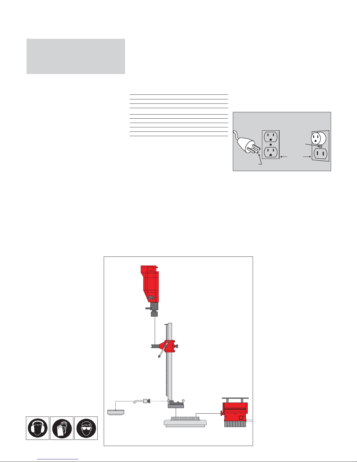
1. DD-80 E/RA diamond coring system
1. DD-80 E motor unit
2. DD 80-RA/DD 100-RA drill stand
3. DD-VH1 vacuum baseplate
4. DD-WC-S water collector
5. DD-HS-RA holder
6. Vacuum pump
DCM 1
DD-80 E
DD-WC-S
DD-VH 1
DD-HS-RA
DD 80-RA
Always wear ear
protectors.
Always wear
protective gloves.
Always wear safety
glasses.
Printed: 07.07.2013 | Doc-Nr: PUB / 5069606 / 000 / 00

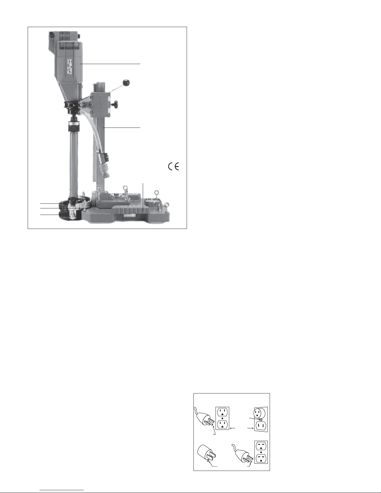
3
2. DD-80 E/RA diamond coring machine
1. Drill stand
1.1 Stop
1.2 Feed locking device
1.3 Hexagon socket wrench
1.4 Carriage
1.5 Levelling screws
1.6 Feed lever or handwheel
2. Motor unit
2.1 On /off switch
2.2 Speed change switch
2.3 Chuck
2.4 Supply cord
2.5 Water connection
2.6 Water regulation valve
3. Water collector
3.1 Sealing disc
4. Water collector holder
4.1 Pressure adjustment screws
5. Vacuum baseplate
3. Safety
3.1 Safety precautions on the jobsite
Before beginning work with the
machine, read the operating instructions carefully and ensure that the
safety precautions listed below are
observed.
I Ensure that no electric cables,
gas or water pipes etc. are situated
where holes are to be cored.
I Cables, pipes or other supply lines
situated in close proximity to where
holes are to be cored must be
switched off.
I The coring work must not have
a negative effect on the structural
design of the building (coring
through steel reinforcement!).
I Cordon off areas where coring
work is taking place, particularly
behind walls or below floors which
are being cored through.
I For overhead coring, the water col-
lector must be in good condition
and function correctly.
I The coring system may only be
operated when an GFCI ground
fault circuit interruptor is connected
in the system.
I In order to provide safe, trouble-free
operation, the coring system must
be kept clean. (Do not clean using a
jet of water.)
I Coring work should only be carried
out by trained personnel who have
received instruction on use of the
equipment.
I When working with the vacuum
baseplate on walls an additional
means of securing the machine
must be employed
(see section 7.3).
I If leakage occurs in the water
supply system, the equipment must
be serviced.
I Do not touch rotating parts.
3.2a Grounding instructions
This tool should be grounded while
in use to help protect the operator
from electric shock. The tool is equipped with a 3-conductor cord and
3-prong grounding type plug to fit the
proper grounding type receptacle. The
green (or green and yellow) conductor
in the cord is the grounding wire. Never connect the green (or green and
yellow) wire to a live terminal.
If your unit is for use on less than
150 V, it has a plug that looks like that
shown in sketch (A) in Figure 1. If it is
for use on 150 to 250 V, it has a plug
that looks like that shown in sketch
(D). An adapter, see sketches (B) and
(C), is available for connecting sketch
3.2b Extension Cords
Use only 3-wire extension cords that
have 3-prong grounding-type plugs
and 3-pole receptacles that accept the
tool’s plug. Replace or repair damaged cords.
(A) type plugs to 2-prong receptacles.
The green colored rigid ear, lug, or the
like, extending from the adapter must
be connected to a permanent ground,
such as a properly grounded outlet
box. No adapter is available for a plug
as shown in sketch (D).
metal screw
cover of grounded
outlet box
grounding pin
grounding
means
grounding pin
GROUNDING METHODS
(A)
(B)
(C) (D)
Figure 1
Printed: 07.07.2013 | Doc-Nr: PUB / 5069606 / 000 / 00

4
Overload indicator:
The overload indicator lights up when
the motor is being operated at maximum load. It is recommended that the
machine is operated so that overload
indicator is not lit up continually e.g.
reduce coring pressure.
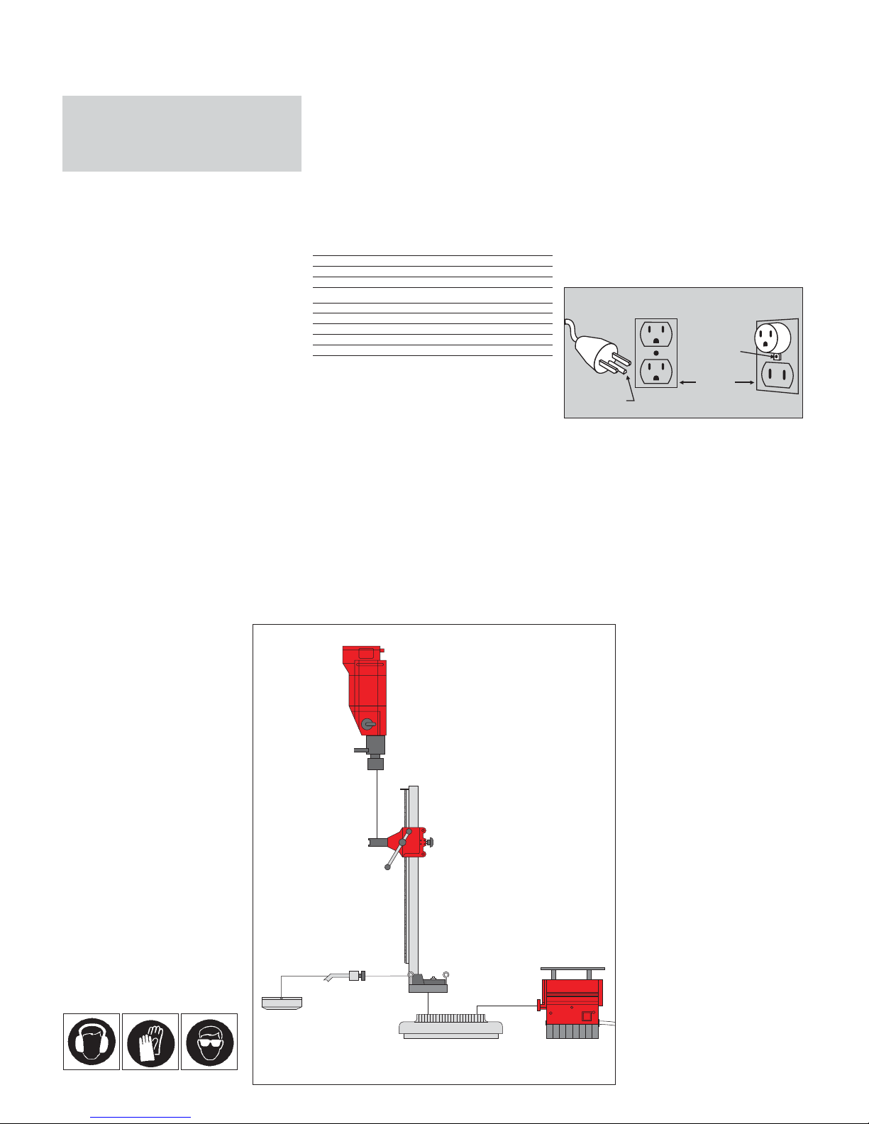
3.4 Instructions and precautions for overhead coring
8. Wet vacuum cleaner.
A vacuum cleaner designed for
removing water and wet materials
must always be used for overhead
coring.
9. 3-way water connection.
Close the water supply valve and
drain the water from the core bit at the
3-way water connection before withdrawing the core bit from the water
collector.
Note: The life of the sealing discs
can be extended by applying a little
grease e.g. bearing grease or Hilti
lubricant spray.
When coring overhead, the following
equipment must be used for safety
reasons:
1. Drill stand, fastened to the ceiling
using an HDI
1
/2˝ anchor
2. Water collector complete with
appropriate sealing disc
3. Hose strain relief clamp
4. Water removal hose
5. Adaptor for wet vacuum cleaner
6. 6 mA GFCI ground fault circuit interruptor (supplied)
7. Supply cord with earth/ground
conductor
1
2
3
4
5
6
7
8
9
3.3 Overload protectors
Hilti diamond coring machines are
equipped with mechanical, electronic,
thermal and optical overload protectors.
Slip clutch:
This protects the motor and core bit in
case the core bit suddenly jams.
Electronic protection:
In case of overloading caused by
excessive coring feed pressure, the
motor current is reduced automatically
so that the core bit then only rotates
slowly. On reducing feed the pressure,
the current input returns to normal and
the motor continues to run at full
power.
Protection against overheating:
The motor is protected against overheating by a sensor which automatically reduces current input in case of
sustained overloading and at high
ambient temperatures. The machine
can be operated normally after the
temperature of the motor windings
has dropped to a satisfactory level.
The motor windings can be cooled
more quickly by allowing the machine
to run without load.
4. Technical data
Voltage 100 V 115 V 230 V
Current input 15 A 15 A 8 A
Power input 1400 W 1600 W 1700 W
Frequency 50/60 Hz
Core bit diameter range 8 – 82 mm
No-load speeds: Speed/core bit diameter range:
1st speed: 1200 r.p.m. 1st speed: 37 – 82 mm
2nd speed: 2400 r.p.m. 2nd speed: 18 – 40 mm
3rd speed: 3900 r.p.m. 3rd speed: 8 – 24 mm
Weight (depending on equipment) approx. 13 kg
Length of supply cord 4 metres
Chuck DD-BI quick-release chuck
Electronic idling speed regulator
Overload current regulator
Optical overload indicator
Built-in starting current regulator
Thermal motor protector
Mechanical slip clutch
Protection class 1 (mains supply with earth/ground connection required)
Radio and TV interference suppression as per EN 55014
Reaction in mains supply as per EN 60555, part 2
Approved as per IEC 1029
The noise produced by this equipment has been measured according to IEC 59
CO 11, IEC 704, DIN 45635, part 21, NFS 31-031 (84/537/ EWG)
The noise level under certain working conditions may exceed 85 dB (A), in which
case the operator must wear suitable ear protectors.
This Product isUL listed andCSA certified
R
Printed: 07.07.2013 | Doc-Nr: PUB / 5069606 / 000 / 00

5
5. Assembling the system components
5.1 Attaching the water collector holder to the drill stand
2
1
3
4
1. Drill stand
2. Holder
3. Screw
4. Wrench
Upper position for use without
vacuum baseplate
Lower position for use with
vacuum baseplate
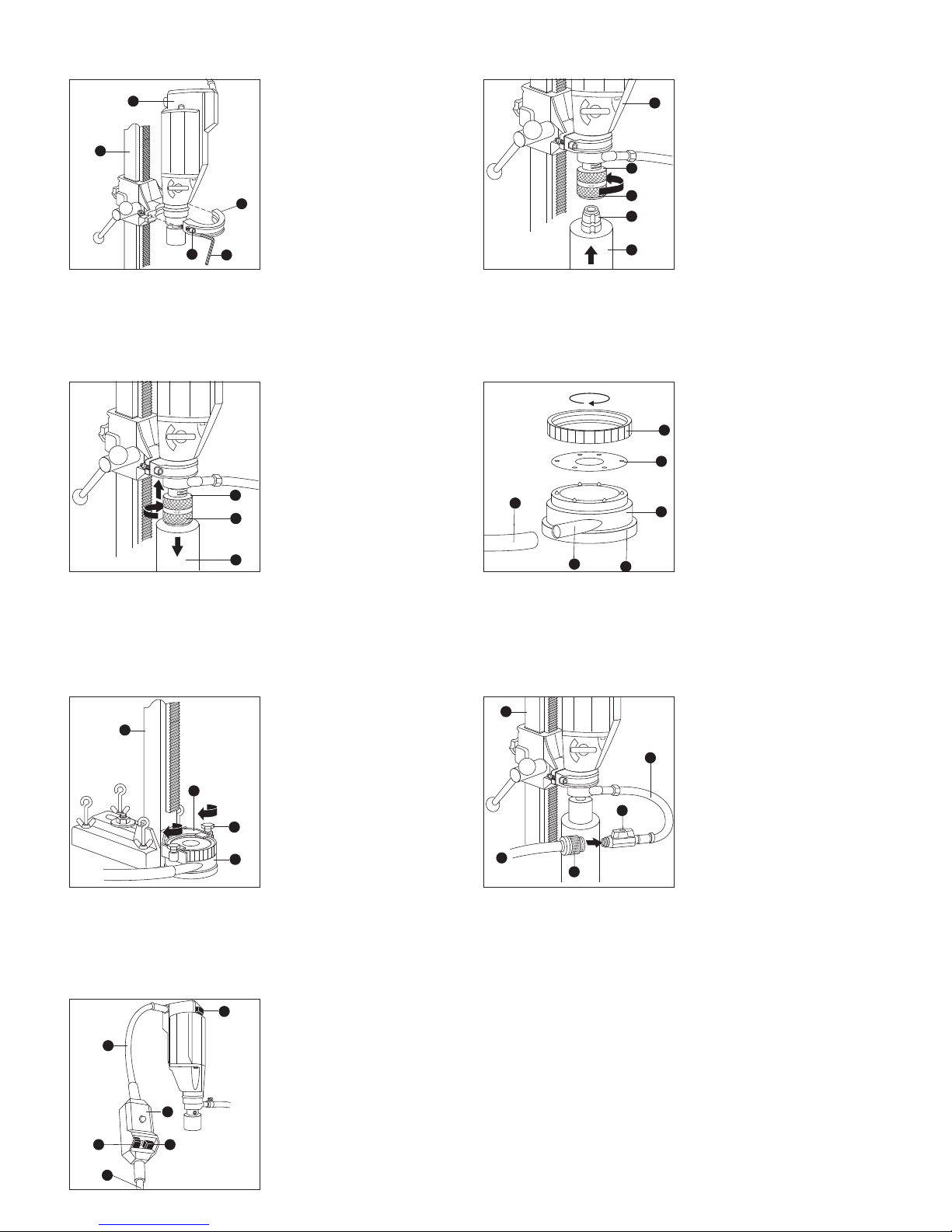
5.2 Changing the chuck
1. Drive shaft
2. Chuck
3. 21 mm AF open-end wrench
4. 30 mm AF open-end wrench
6.2 Fastening the unit using the vacuum baseplate
– Quick fastening method
– No need to drill anchor holes
Caution: Must be secured additionally
for wall applications with chain, rope,
brace or support to support a load of
at least 300 kg.
For ceiling applications the use of a
vacuum baseplate not allowed.
The coring system must not
be operated before fastening the
baseplate!
6. Selecting the method of fastening the coring unit
6.1 Anchor fastening
– Secure method of fastening for high
coring performance
– Versatile method (suitable for wall,
ceiling and floor)
– Can also be used on uneven and
rough surfaces
Caution: The coring system must
not be operated before fastening the
baseplate!
3
4
2
O
P
E
E
N
C
L
O
S
E
1
7. Preparing the coring system for use
7.1 Fastening the drill stand using the bracing spindle and an anchor
180 mm
2
1
3
4
5
6
1. HDI1/2˝ internally threaded
anchor (on concrete)
2. Bracing spindle
3. Drill stand
4. Washer
5. Bracing spindle nut
6. 19 mm AF open-end wrench
The drill stand is most rigid when the
anchor is positioned at the front end of
the anchor slot (closest to column).
Recommended maximum distance
from anchor to hole centre – 180 mm
7. 2 Fastening the drill stand using an anchor and bracing spindle (continued)
100 m m
– After tightening the bracing spindle
not, the levelling screws (in diagonal
sequence) until the baseplate is rigid
and secure.
– Distance from baseplate to centre of
hole drilled – 100 mm
7.3 Fastening the vacuum baseplate
2
1
3
4
5
6
7
8
9
1. Vacuum pump
2. Vacuum connection
3. Vacuum baseplate
4. Grip
5. Release valve
6. Hole centre indicator
7. Vacuum indicator must remain
within the green area
8. Levelling screws
9. Securing chain, rope, brace or
support (see also section 6.2)
Unscrew the levelling screws sufficiently and check the seal for damage
before positioning the baseplate.
7.4 Attaching the drill stand to the vacuum baseplate
2
1
3
4
5
1. Bracing spindle
2. Drill stand
3. Washer
4. Bracing spindle nut
5. 19 mm AF open-end wrench
The coring system does not stand
securely until vacuum pressure has
been applied to the baseplate.
After applying the vacuum, tighten
the levelling screws by hand as far as
they will go, following a diagonal
sequence.
Printed: 07.07.2013 | Doc-Nr: PUB / 5069606 / 000 / 00
6
7.5 Mounting the motor unit on the drill stand
2
1
3
4
5
1. Motor unit
2. Drill stand
3. Clamping bar
4. Clamping screw
5. Wrench
7.6 Fitting a core bit
1. Chuck
2. Connection end
3. Core bit
4. Locking sleeve
5. Motor unit
7.7 Releasing a core bit
1. Chuck
2. Core bit
3. Locking sleeve
Hold the core bit before disengaging
the locking sleeve.
When the core bit is released, ensure
that the core does not accidentally fall
out of the bit.
When drilling overhead, close the
water supply valve and drain the core
bit via the water supply hose before
releasing it from the chuck
(see section 3.4).
7.8 Inserting a sealing disc in the water collector
2
1
3
4
5
6
1. Water collector
2. Sealing disc
(select correct diameter)
3. Clamping ring
4. Hose connection
5. Sealing ring
6. Water removal hose
A water removal system and a sealing
disc in new condition must always be
used for overhead coring.
O
P
E
N
C
L
O
S
E
1
3
5
2
4
O
P
E
N
C
L
O
S
E
2
1
3
7.9 Attaching the water collector
2
1
3
4
1. Drill stand
2. Water collector holder
3. Water collector
4. Pressure screws
Tighten the pressure screws evenly.
Use of the water collector is mandatory for overhead coring and is also
recommended for all other coring
positions.
7.10 Connecting the water supply
2
1
3
4
5
1. Drill stand
2. Water hose
3. Water valve
4. Hose connector
5. Water supply
Water supply pressure must not
exceed 145 PSI.
7.11 Connecting the mains supply (115 V motor unit)
(Mains socket with earth/ground connection required, 15 A fuse rating)
2
1
3
4
5
6
115V
1. Motor unit ON / OFF switch
2. Supply cord
3. GFCI ground fault circuit interruptor
4. GFCI test button
5. GFCI ON-switch
6. Mains plug specific to country
The DD-80 E comes equipped with a
GFCI included in the power cord. The
GFCI must be operated according to
the following instructions.
1. Plug the GFCI into a 120 VAC
grounded receptacle.
2. Press “Test“ button. “Fault Light“
should come on.
3. Press “Reset“ button. “Fault Light“
should go off.
4. Do not use the DD-80 E if the GFCI
fails this test. Return to Hilti for servicing.
After every fault or interruption in the
mains supply, switch off the motor unit
before resetting the GFCI interruptor.
Printed: 07.07.2013 | Doc-Nr: PUB / 5069606 / 000 / 00

7
8. Operation
8.1 Operation
2
1
3
4
5
6
7
1. Select the correct coring speed.
(Change speed only when rotation
has stopped.)
2. Release the carriage locking device.
3. Guide the core bit into the water
collector.
4. Open the water supply valve.
5. Switch on the motor.
Pay attention to the overload indicator
(6) and vacuum meter (7) while coring.
8.2 Tips
I Reduce feed pressure and tighten
carriage locking device slightly when
starting holes in order to avoid vibration.
I If steel reinforcement is contacted,
select lower coring speed and
reduce water flow. (Obtain permission from site manager or engineer
before cutting through steel reinforcement.)
The diamond segments can become
polished (reduced cutting performance) if the coring feed pessure is
too low.
I Inadequate water flow will cause the
core bit to overheat, resulting in permanent damage.
I Reduce coring feed pressure if the
overload indicator lights up.
I Water flow rates
8–47 mm max. 1–1,5 l/min.
52–82 mm max. 3 l/min.
9. Maintenance
9.1 In order to provide trouble-free operation, the following points must be
observed:
1 Motor unit
I Keep the chuck clean and well
lubricated.
I Keep the ventilation slots in the
motor housing free of dirt and dust.
I Check the system regularly for
water leakage.
2 Drill stand
I Keep the column / guide rail clean.
9.2 Wearing parts
I DD-VH2 replacement seal for the
vacuum baseplate
I DD-WC-S sealing disc for the water
collector
I DD-WC-S sealing ring for the water
collector
In case of technical problems,
please contact the Hilti customer
service department.
3 Vacuum baseplate
I With the exception of the seals, the
vacuum baseplate requires no
maintenance.
10. Disposal
Return waste material for recycling
Most of the materials from which Hilti
tools or machines are manufactured can
be recycled. The materials must be
correctly separated before they can be
recycled.
In many countries, Hilti has already made
arrangements for taking back your old
machines or tools for recycling. Please
ask your Hilti customer service department or Hilti sales representative for further information.
Disposal of drilling slurry
With regard to environmental aspects,
allowing drilling slurry to flow directly
Only for EU countries
Do not dispose of electric tools together with household waste material!
In observance of European Directive 2002/96/EC on waste electrical and
electronic equipment and its implementation in accordance with national law,
electric tools that have reached the end of their life must be collected separately
and returned to an environmentally compatible recycling facility.
Hilti warrants that the product supplied
is free of defects in material and workmanship. This warranty is valid as long
as the product is operated and handled
correctly, cleaned and serviced properly
and in accordance with the Hilti operating instructions, all warranty claims
made within 6 months (machine) or 12
months (other items of equipment) from
the date of the sale (invoice date), unless
other mandatory national regulations
prescribe a longer minimum period, and
the technical system is maintained.
This means that only genuine Hilti consumables, components and spare parts
maybeusedwiththeproduct.
This warranty provides the free-of-charge
repair or replacement of defective parts
only. Parts requiring repair or replacement as a result of normal wear and tear
are not covered by this warranty.
Additional claims are excluded, unless
stringent national rules prohibit such
exclusion. In particular, Hilti is not
obligated for direct, indirect, incidental
or consequential damages, losses or
expenses in connection with, or by
reason of, the use of, or inability to use
the product for any purpose. Implied
warranties of merchantability or fitness
for a particular purpose are specifically
excluded.
Send the product and/or related parts
immediately upon discovery of a defect
to the local Hilti marketing organization
for repair or replacement.
This constitutes Hilti's entire obligation
with regard to warranty and supersedes
all prior or contemporaneous comments
and oral or written agreements
concerning warranties.
11. Warranty
into rivers, lakes or the sewerage system
without suitable pre-treatment is problematical. Ask the local authorities for
information about applicable regulations.
We recommend the following pretreatment:
Collect the drilling slurry (e.g. use a wettype industrial vacuum cleaner).
Allow the slurry to settle and dispose of
the solid material at a construction waste
disposal site (the addition of a flocculent
may accelerate the settling process).
Water from the drilling slurry (alkaline,
ph value > 7) should be neutralized by
adding an acidic neutralizing agent or
large quantity of water before it is
allowed to flow into the sewerage system.
Printed: 07.07.2013 | Doc-Nr: PUB / 5069606 / 000 / 00
8
Directives de sécurité pour des
appareils mis à la terre
Lire toutes les instructions!
1. Garder propre l’endroit où vous travaillez. Tout désordre sur votre lieu de
travail ou votre établi peut entraîner un risque d’accident.
2. Tenir compte du milieu ambiant à l’endroit où vous travaillez. Eviter de
travailler avec vos appareils électroportatifs sous la pluie, de les utiliser dans
un milieu ambiant humide ou mouillé. L’endroit où vous travaillez devra toujours être bien éclairé. Ne pas utiliser d’appareil près de liquides ou de gaz
inflammables.
3. Vous protéger de toute électrocution. Ne jamais toucher de surfaces
reliées à la terre telles que tuyaux, radiateurs, cuisinières, enceintes de réfrigérateurs.
4. Tenir les enfants éloignés. Interdire à tous visiteurs de toucher l’appareil
ou un prolongateur. Il est conseillé de les tenir éloignés de l’endroit où vous
travaillez.
5. Ranger les appareils en position d’arrêt. Les appareils que vous n’utilisez
pas devraient être rangés dans un endroit sec, en hauteur ou fermé à clé –
hors de portée des enfants.
6. Ne pas forcer sur l’appareil. II fournira un meilleur travail, avec une plus
grande sécurité, au régime pour lequel il est prévu.
7. Utiliser le bon appareil. Ne pas forcer sur un appareil ou un accessoire
trop petit pour faire le travail d’un plus gros appareil. Ne pas utiliser un appareil pour un but pour lequel il n’est pas prévu – p. ex. – ne pas utiliser une scie
circulaire pour couper des branches d’arbres ou des grumes.
8. Porter des vêtements appropriés. Ne pas porter de vêtements amples, ni
de bijoux. Ils risquent d’être happés par des pièces en mouvement. Pour travailler à l’extérieur, il est conseillé d’utiliser des gants en caoutchouc et de porter des chaussures à semelle antidérapante. Porter un casque ou une casquette si vous avez les cheveux longs.
9. Porter des lunettes de protection. Si l’opération de coupe dégage de la
poussière, porter aussi un masque (de protection).
10. Ne pas maltraiter le cordon. Ne jamais porter l’appareil en le tenant par
le cordon et ne pas tirer d’un coup sec pour débrancher l’appareil de la prise.
Protéger le cordon de la chaleur, ne pas le souiller avec de l’huile et éviter les
bords tranchants.
11. Bloquer la pièce pour travailler. Utiliser des mâchoires ou un étau pour
tenir la pièce. C’est plus sûr que de la tenir à la main et vous aurez ainsi les
deux mains libres pour faire fonctionner l’appareil.
12. Ne pas trop vous pencher en avant/garder votre équilibre. Bien rester
en équilibre sur les deux pieds à tout moment.
13. Prendre soin de vos appareils. Garder vos outils bien affûtés et propres
pour obtenir de meilleures performances et travailler avec une plus grande
sécurité. Suivre les instructions pour lubrifier les outils et changer d’accessoires. Inspecter régulièrement les cordons des appareils et, s’ils sont abîmés, les faire réparer par un atelier de réparation agréé. Inspecter régulièrement les prolongateurs et les remplacer s’ils sont abîmés. Tenir les poignées
propres, au sec et éviter de les souiller avec de l’huile ou de la graisse.
14. Débrancher les appareils si vous ne les utilisez pas, avant de les réviser
ou de changer d’accessoire, de mèche, de lame p. ex..
15. Enlever les clés (de réglage entre autres). Prendre l’habitude de vérifier
si les clés (de réglage entre autres) ont bien été enlevées de l’appareil avant de
le mettre en marche.
16. Eviter toute mise en marche intempestive. Ne pas transporter l’appareil
en gardant le doigt sur l’interrupteur. Vous assurer que l’interrupteur est bien
à l’arrêt avant de brancher l’appareil.
16A. Prolongateurs. Vous assurer que votre prolongateur est en bon état.
Utiliser un prolongateur suffisamment gros pour transporter le courant qui
entraînera votre appareil. Si le cordon est sous-dimensionné, il risque de provoquer une chute de tension se traduisant par une perte de puissance et une
surchauffe. Le tableau ci-après montre les dimensions correctes du prolongateur à utiliser suivant la longueur du cordon et l’ampérage de la plaquette. En
cas de doute, utiliser la dimension immédiatement supérieure. Plus la dimension est petite, plus le cordon doit être gros.
Tableau des longueurs de cordons
Volts Longueur totale de cordon en pieds
120 V 0–25 26– 50 51–100 101–150
240 V 0–50 51–100 101–200 201–300
Ampérage Grosseur de fil
Plus de Pas plus de
0 6 18 16 16 14
610 18161412
10 12 16 16 14 12
12 16 14 12 Déconseillé
17. Prolongateurs pour utilisation à l’extérieur. Pour utiliser un appareil à
l’extérieur, n’utiliser des prolongateurs que s’ils sont bien autorisés pour le
but prévu et bien marqués en conséquence.
18. Restez attentif. Regardez ce que vous faites. Faites preuve de bon sens.
Ne faites pas fonctionner l’appareil si vous êtes fatigué.
19. Vérifier si les pièces sont abîmées. Avant de continuer à utiliser l’appareil, vérifier soigneusement si un carter de protection ou une autre pièce
n’est pas abîmé(e), s’il(si elle) fonctionne correctement et remplit bien la
fonction prévue. Vérifier si les pièces en mouvement sont bien réglées, ne
grippent pas, si des pièces ne sont pas cassées, si elles sont bien assemblées et si toutes les autres conditions qui pourraient influer sur leur fonctionnement sont bien remplies. Si un carter de protection ou une autre pièce
sont abîmés, les faire réparer ou remplacer par un atelier de réparation
agréé, sauf autre instruction dans le présent mode d’emploi. Faire réparer
aussi par le même atelier les interrupteurs s’ils sont défectueux. Ne pas utiliser l’appareil si l’interrupteur ne fonctionne pas correctement.
20. Utiliser uniquement les accessoires et kits de fixation qui sont indi-
qués dans le mode d’emploi ou dans le catalogue respectif. Si vous utilisez
des accessoires, des inserts ou des kits de fixation autres que ceux spécifiés
dans le mode d’emploi, vous pouvez vous blesser.
21. Faire effectuer les réparations uniquement par des électriciens spécialisés agréés. Cet appareil électroportatif est conforme aux règlements de
sécurité en vigueur. Toutes réparations ne peuvent être effectuées que par un
électricien spécialisé, sous peine de risque d’accident pour l’utilisateur.
22. Porter un casque antibruit si vous travaillez longtemps.
23. Si la poignée latérale est fournie, toujours l’utiliser et vous assurer
qu’elle est bien bloquée; utiliser l’appareil à deux mains. Bien rester en équilibre sur les deux pieds à tout moment. Ne pas trop vous pencher en avant.
Si la mèche vient à coincer, tenir fermement l’appareil.
24. Tenir l’appareil par la(les) poignée(s) fournie(s). Ne pas toucher des
parties non isolées de l’appareil lors du perçage. Les surfaces métalliques à
nu peuvent être rendues conductrices si l’appareil vient à toucher un fil électrique lors du perçage.
25. Instructions de mise à la terre. Cet appareil devrait être mis à la terre
pendant son utilisation pour protéger l’opérateur de toute électrocution. Cet
appareil est équipé d’un cordon à 3 conducteurs et d’une fiche du type mise
à la terre à 3 broches qui s’adapte dans la prise mise à la terre. Le conducteur vert (ou vert et jaune) du cordon est le fil de mise à la terre. Ne jamais
connecter le fil vert (ou vert et jaune) à une borne conductrice. Si votre appareil doit être utilisé sur une tension inférieure à 150 volts, il est muni d’une
fiche comme illustré schéma (A), figure «Méthodes de mise à la terre». Un
adaptateur, voir schéma (B), est disponible pour relier les fiches de type
schéma (A) à des prises à deux trous. L’oreille rigide couleur verte, la cosse
ou tout autre, provenant de l’adaptateur, doit être connectée et mise à la terre
en permanence, comme p. ex. à une prise mise correctement à la terre.
26. Prolongateurs. Utiliser uniquement des prolongateurs à 3 conducteurs
avec des fiches du type mise à la terre à 3 broches qui s’adaptent dans des
prises à 3 trous. Si les cordons sont abîmés, les remplacer ou les réparer.
27. Pièces de rechange. Pour les réparations et les révisions, utiliser uniquement des pièces de rechange d’origine.
Ranger ces directives de sécurité dans un endroit sûr!
Avertissement!
Lors de l’emploi de machines/d’appareils électroportatifs, l’utilisateur
devra toujours observer les directives de sécurité de base suivantes
de manière à toujours être bien protégé de toute électrocution, des
risques d’accident ou des risques dus au feu. Avant d’utiliser la
machine/l’appareil, lire attentivement ces directives de sécurité, bien
en tenir compte et les conserver dans un endroit sûr!
vis métallique
plaque d'une boîte de
raccordement
correctement mise à la terre
broche de mise à la terre
MÉTHODES DE MISE À LA TERRE
(A)
(B)
Contents Page
Directives de sécurité 8
1. Système de carottage
au diamant DD-80 E/RA 8
2. Appareil de carottage
au diamant DD-80 E/RA 9
3. Directives de sécurité
additionnelles 9
4. Fiche technique 10
5. Assemblage des composants
du système 11
6. Choix d’une méthode
pour immobiliser l’appareil
de carottage 11
7. Préparation de l’appareil
de carottage 11
8. Mode d’emploi du système 13
9. Entretien 13
10. Garantie 13
1. Le système de carottage au diamant DD-80 E/RA
1. Bloc-moteur DD-80 E
2. Colonne DD 80-RA/DD 100-RA
3.Base à succion DD-VH 1
4. Collecteur d’eau DD-WC-S
5. Support DD-HS-RA
6. Pompe à vide
DCM 1
DD-80 E
DD-WC-S
DD-VH 1
DD-HS-RA
DD 80-RA
Porter un casque
antibruit.
Porter des gants de
sécurité.
Porter des lunettes
de protection.
Printed: 07.07.2013 | Doc-Nr: PUB / 5069606 / 000 / 00
9
2. Appareil de carottage au diamant DD-80 E/RA
1. Colonne
1.1 Butée
1.2 Blocage de la descente
1.3 Clé hexagonale
1.4 Chariot
1.5 Vis de mise à niveau
1.6 Volant ou levier de descente
2. Bloc-moteur
2.1 Interrupteur
2.2 Commutateur de changement de vitesse
2.3 Mandrin
2.4 Cordon d’alimentation
2.5 Prise d’eau
2.6 Régulateur du débit d’eau
3. Collecteur d’eau
3.1 Disque étanche
4. Support pour le collecteur d’eau
4.1 Vis de réglage de la pression
5. Base à succion
3. Directives de sécurité additonnelles
3.1 Directives de sécurité pour le chantier
Avant de vous servir du système de
carottage, veuillez lire attentivement
les directives de sécurité et suivre les
mesures de prévention qui figurent cidessous.
I Assurez-vous qu’aucun fil élec-
trique, tuyau ou conduite de gaz,
etc., ne passe à l’endroit où vous
comptez carotter.
I Coupez l’alimentation aux câbles,
tuyaux et autres lignes d’alimentation qui se trouvent à proximité de
l’emplacement où vous comptez
carotter.
I Le carottage ne doit pas nuire à la
structure du bâtiment (carottage de
l’armature d’acier!).
I Interdisez l’accès aux lieux où se
déroule le carottage, particulièrement ceux qui se trouvent derrière
le mur ou sous le plancher qui doit
être perforé.
I Pour le carottage au plafond,
assurez-vous que le collecteur et le
système d’extraction de l’eau sont
en bon état de marche.
I Servez-vous du système de carot-
tage uniquement s’il comporte un
interrupteur de mise à la terre
défectueuse.
I Pour qu’il fonctionne sans ennuis et
en toute sécurité, le système de
carottage doit être propre. (Ne le
nettoyez pas à l’aide d’un jet d’eau.)
I Le carottage doit être exécuté
exclusivement par des ouvriers
qualifiés qui ont été formés à
l’usage de l’équipement.
I Lorsque vous utilisez la base à suc-
cion sur un mur, vous devez faire
appel à une seconde méthode pour
immobiliser l’appareil (vour la section 7.3).
I S’il y a une fuite dans le système
d’alimentation en eau, l’équipement
doit être vérifié.
3.2a Directives de mise à la terre
Lorsqu’il est en usage, cet outil doit
être mis à la terre afin d’aider à protéger son utilisateur contre les
décharges électriques. L’outil est doté
d’un cordon à trois conducteurs et
d’une fiche à trois broches qui se
branchent sur une prise de courant à
trois broches avec mise à la terre. Le
conducteur à gaine verte (ou vert et
jaune) du cordon est le fil de terre. Ne
raccordez jamais le conducteur à
gaine verte (ou vert et jaune) sur une
borne sous tension.
Si votre appareil est conçu pour fonctionner à une tension inférieure à 150
V, il sera doté d’une fiche semblable à
celle illustrée en A à la figure 1. S’il est
3.2b Rallonges
Servez-vous exclusivement de rallonges à trois conducteurs dotées
d’une fiche à trois broches et d’une
prise à trois broches qui s’adapte à la
fiche de l’outil. Veuillez remplacer ou
réparer les rallonges endommagées.
conçu pour fonctionner à une tension
qui se situe entre 150 V et 250 V, il
sera doté d’une fiche semblable à
celle illustrée en D. Il est possible de
se procurer un adaptateur (illustré en
B et C) servant à raccorder une fiche
semblable à celle illustrée en A sur une
prise de courant à deux sorties. La
borne rigide de couleur verte qui
dépasse de l’adaptateur doit être raccordée sur une prise de terre permanente, comme par exemple une boîte
de raccordement correctement mise à
la terre. Il n’existe pas d’adaptateurs
pour les fiches semblables à celle
illustrée en D.
vis métallique
plaque d'une boîte de
raccordement
correctement mise à la terre
broche de mise
à la terre
prise de
terre
broche de mise à la terre
MÉTHODES DE MISE À LA TERRE
(A)
(B)
(C) (D)
Figure 1
I Ne toucher aucune pièce en
rotation.
Printed: 07.07.2013 | Doc-Nr: PUB / 5069606 / 000 / 00
 Loading...