

Page 1

DD200
*305560*
305560
Bedienungsanleitung de
Operating instructions en
Mode d’emploi fr
Istruzioni d’uso it
Gebruiksaanwijzing nl
Manual de instruções pt
Manual de instrucciones es
Οδηγιες χρησεως
el
Page 2

1
9
32
13
14
22
23
28
7
9
26
14
15
28
41
42
40
43
16
18
17
31
39
19
29
27
25
29
24
21
20
30
33
10
6
5
2
4
8
3
11
12
34
38
37
36
35
Page 3

2
2
4
6
3
5
7
3
3
2
1/3
1
2
1
4/6
2
5
3
1
2
5
6
8
8
7
9
6
5
1/12
11
3
10
42
6
3/5
4
1
4
2
1/3
2
1/3
Page 4

8
10
12
9
11
13
3
1
2
3
5
2/4
1
3
5
2/4
1
5
1/3
4
6
2
1
2/4
3
1
2
Page 5
14
16
18
15
17
19
6
4/5
2
3
1
6
2
4/5
3
1
8
1
4
6/7
5
3
2
5
2
6
4
3
1
2
5
3/4/6
1
1/3
2
Page 6

15
en
It is essential that the operating instructions
are read before the machine is operated for
the first time.
Always keep these operating instructions
together with the machine.
Ensure that the operating instructions are
with the machine when it is given to other
persons.
DD200 diamond core drilling system
1. General information
1.1 Safety notices and their meaning
-DANGER-
Draws attention to imminent danger that could lead to
serious bodily injury or fatality.
-CAUTION-
Draws attention to a potentially dangerous situation that
could lead to slight personal injury or damage to the
equipment or other property.
-NOTE-
Draws attention to instructions and other useful information that help the user to employ the product efficiently.
Contents Page
1. General information 15
2. Description 17
3. Tools and accessories 17
4. Technical data 17
5. Safety precautions 18
6. Before use 20
7. Operation 23
8. Care and maintenance 25
9. Troubleshooting 26
10. Disposal 27
11. Warranty 28
12. EC declaration of conformity 28
Operating controls, parts and indicators
Drilling rig (drive unit and drill stand)
Drive unit
; Service indicator
= Drilling performance indicator
% On / off switch
& Gear selector switch
( Water flow regulator
) Chuck
+ Supply cord with PRCD
§ Carrying grips (2)
/ Water hose connector
: Type plate
· Interface
Drill stand
$ Column
£ End cap
| Strut
¡ Base plate
Q Clamping spindle
W Clamping nut
E Anchor
R Leveling screws
T Hole center indicator
Z Carriage
U Drive unit (eccentric) locking bolt
I Direct drive
O Reduction gear
P Carriage locking mechanism
Ü Hand wheel
[ Carrying grip
] Supply cord guide
Æ Type plate
º Leveling indicators (2)
• End stop
A Wheel assembly mounting point
ACCESSORIES
Vacuum base plate
S Pressure gauge
D Vacuum release valve
F Vacuum seal
G Vacuum hose connector
H Wheel assembly mounting point
Water flow indicator
J Water flow indicator
Water collector system
K Water collector holder
L Water collector
Ö Seal
Ä Seal
Column extension
† Eccentric bolt
Depth gauge
Spacer
ΠDrive unit locking mechanism
Wheel assembly
Å Set of wheels
Page 7

16
en
Prohibition signs
Transport by
crane is not
permissible.
1.2 Pictograms
Warning signs
General
warning
Recycle
waste
material
Warning:
electricity
Warning: hot
surface
Read the operating
instructions before
use.
Symbols
On the vacuum baseplate On the tool
VACUUM
VACUUM
Top:
An additional means of
securing the drill stand must
be employed when used for
horizontal drilling with
vacuum attachment.
Below:
Use of only the vacuum baseplate to secure the drill stand
for overhead drilling is not
permissible.
Use of the water collector
system in conjunction with a
wet-type vacuum cleaner is
mandatory when working
overhead on ceilings.
These numbers refer to the corresponding illustrations. The illustrations can be found on the fold-out cover pages. Keep these pages open while studying the
operating instructions.
In these operating instructions, the designation "the
machine" refers to the DD 200 core drilling machine.
Location of identification data on the machine
The type designation and serial number can be found
on the rating plate on the machine. Make a note of this
data in your operating instructions and always refer to
it when making an enquiry to your Hilti representative
or service department.
Type: DD 200
Serial no.:
Type: DD-HD 30
Serial no.:
Use of a correctly functioning PRCD
circuit breaker is mandatory.
PRCD
GFCI
208188 B/2.2004
Page 8

17
en
2. Description
2.1 Use of the equipment as intended
The DD 200 and DD HD-30 form a drilling rig designed
for wet core drilling in mineral materials using diamond
core bits (hand-held use is not permissible).
The drive unit must always be mounted on the drill stand
when in use and the drill stand secured adequately by
means of an anchor, vacuum base plate or quick-release
brace.
Manipulation or modification of the drive unit, drill stand
or accessories is not permissible. To avoid the risk of
injury, use only original Hilti accessories and insert tools.
Observe the information printed in the operating instruc-
tions concerning operation, care and maintenance.
Observe the safety precautions and operating instructions for the accessories used.
Do not use a hammer or other heavy object when making adjustments to the baseplate.
The drive unit, drill stand, accessories and insert tools
may present hazards when used incorrectly by untrained
personnel or not as directed.
The machine may be operated only when connected to
an adequately rated electric supply equipped with an
earth / ground conductor.
3. Accessories
Water flow indicator 305939
Depth gauge 305535
Water collector holder 305536
Column extension 305537
Vacuum base plate 305538
Vacuum pump 332158; 92053 (USA)
Spacer 305539
Wheel assembly 305541
Clamping spindle 305940
Clamping nut 251834
Quick-release brace 9870
Water collector 25-162 232221
Water collector 92-250 232243
Water collector 8-87 232204
Equipment Core bits Drilling direction
System with water collector and wet-type vacuum cleaner 25–250 mm dia. All directions
System without water collector and wet-type vacuum cleaner 25–400 mm dia. Not upwards
System with water collector 25–250 mm dia. Not upwards
Use of the water collector system in conjunction with a
wet-type vacuum cleaner is mandatory when working
overhead on ceilings.
Use of the quick-release brace is not permissible for working on ceilings.
Horizontal drilling in conjunction with the vacuum base
plate (accessory) is permissible only when an additional means of securing the drill stand is employed.
Drilling into materials hazardous to the health (e.g.
asbestos) is not permissible.
4. Technical data
Drive unit DD 200
Rated voltage* 100 V 110 V 220 V 230 V 230 V 240 V
Rated power input* 2300 W 2500 W 2600 W 2600 W
Rated current* 15 A
Rated frequency 50/60 Hz 50/60 Hz 50/60 Hz 50/60 Hz 50/60 Hz 50/60 Hz
Nominal speed under no load (r.p.m.) 380/640/1300 320/550/1120
Max. permissible water supply
pressure 6 bar
Page 9

18
en
Dimensions (LxWxH) 630×150×173 mm
Weight (drive unit) 12.7 kg
Weight (drill stand) 17.9 kg
Drilling depth max. 500 mm without extension
Protection class as per EN/IEC 61029 protection class I (earthed)
Noise and vibration information (measured in accordance with EN 61029-1):
Typical A-weighted noise power level (LwA): 105 dB (A)
Typical A-weighted noise emission pressure level (LpA): 92 dB (A)
Wear ear protection
Typical weighted vibration at the hand wheel: < 2,5 m/s
2
Interference immunity as per EN 55014-2
Radio and television interference suppression as per EN 55014-1
* The machine is available in several versions with different voltage ratings. Please refer to the type plate for the voltage rating and input power
rating of your machine.
5. Safety precautions
CAUTION: The following basic safety precautions must
always be observed when using electric machines in
order to avoid the risk of electric shock, injury or fire.
Read all of these instructions before using this machine
and keep this list of safety precautions for future reference.
5.1 The necessary safety precautions at the workplace
● Approval must be obtained from the site engineer or
architect prior to beginning drilling work. Drilling work
on buildings and other structures may influence the
statics of the structure, especially when steel reinforcing bars or load-bearing components are cut through.
● Ensure that the workplace is well lit.
● Ensure that the workplace is well ventilated.
● Keep the workplace tidy. Objects which could cause
injury should be removed from the working area. Untidiness at the workplace can lead to accidents.
● When drilling through-holes, the area below the ceil-
ing, floor or behind the wall where the drilling is taking place must be secured as the drilled-out core may
fall out.
● Use clamps or a vice to secure the workpiece. The
workpiece is thus held more securely than by hand and
both hands remain free to operate the machine.
● Use protective equipment. Wear eye protection.
● Wear breathing protection if the work creates dust.
● Wear suitable working clothing. Do not wear loose
clothing, loose long hair or jewelry as it can become
caught up in moving parts. Wear suitable headgear if
you have long hair.
● It is recommended that rubber gloves and non-slip
shoes are worn when working outdoors.
● Keep children and other persons away from the work-
ing area.
● Do not allow other persons to tamper with the machine
or the supply cord.
● Avoid unfavorable body positions. Work from a secure
stance and stay in balance at all times.
● To avoid tripping and falling when working, always lead
the supply cord, extension cord and water hose away
to the rear.
● Keep the supply cord, extension cord, water hose and
vacuum hose away form rotating parts of the machine.
● CAUTION: Before beginning drilling, check that there
are no live electric cables located in the area where
the hole is to be made.
● Concealed electric cables or gas and water pipes pre-
sent a serious hazard if damaged while you are working. Accordingly, check the area in which you are working beforehand (e.g. using a metal detector). External
metal parts of the machine may become live, for example, when an electric cable is drilled into inadvertently.
● Do not work from a ladder.
Page 10

19
en
5.2 General safety precautions
● Use the right machine for the job. Do not use the
machine for purposes for which it was not intended.
Use the machine only as directed and when it is in
faultless condition.
● Use only the original accessories or ancillary equip-
ment listed in the operating instructions. Use of other insert tools or accessories may present a risk of
personal injury.
● Take the influences of the surrounding area into account.
Do not expose the machine to rain or snow and do
not use it in damp or wet conditions. Do not use the
machine where there is a risk of fire or explosion.
● Keep the grips dry, clean and free from oil and grease.
● Do not overload the machine. It will work more effi-
ciently and more safely within its intended performance range. The side handle must be fitted for all
types of work.
● Never leave the machine unattended.
● When not in use, the machine must be stored in a dry
place, locked up or out of reach of children.
● Avoid unintentional starting. Check that the on / off
switch is in the "off” position before plugging the supply cord into the electric socket.
● Unplug the machine from the electric supply when it
is not in use, during pauses between work, before
maintenance and when changing core bits.
● Check the PRCD each time before use.
● Take care of your core bits. You will be able to work
more efficiently and more safely if the core bits are
kept sharp and clean.
● Check the machine for possible damage. Protective
devices and any parts that may have suffered slight
damage should be checked for correct operation and
functionality before further use. Check that moving
parts function correctly without sticking and that no
parts are damaged. All parts must be fitted correctly
and fulfill all conditions necessary for correct operation of the machine. Damaged safety devices or other damaged parts must be replaced or repaired properly by an authorized repair workshop unless otherwise indicated in the operating instructions.
● Avoid skin contact with drilling slurry.
● Wear respiratory protection when the work creates
dust, e.g. during dry drilling. Connect a vacuum cleaner to the drilling system. Drilling into materials that
present a health hazard (e.g. asbestos) is not permissible.
5.2.1 Mechanical hazards
● Follow the instructions concerning care and mainte-
nance.
● Check that the insert tools used are compatible with
the chuck system and that they are secured in the
chuck correctly.
● Make sure that the machine is correctly and securely
attached to the drill stand.
● Do not touch rotating parts.
● Make sure that all clamping screws are tightened cor-
rectly.
● After detaching the column extension, the end cap
(with built-in, safety-relevant end stop function) must
be refitted to the drill stand.
5.2.2 Electrical hazards
● Protect yourself against electric shock. Avoid body
contact with earthed / grounded objects, e.g. pipes,
radiators, cookers and fridges.
● Check the condition of the supply cord and its plug
connections and have it replaced by a qualified electrician if damage is found. Check the condition of the
extension cord and replace it if damage is found.
● Check the condition of the machine and its acces-
sories. Do not operate the machine or its accessories
if damage is found, if the machine is incomplete or if
its controls cannot be operated faultlessly.
● Do not touch the supply cord in the event of it suffer-
ing damage while working. Disconnect the supply cord
plug from the socket.
● Damaged or faulty switches must be replaced at a Hilti
service center. Do not use the machine if it cannot be
switched on and off correctly.
● Have the machine repaired only by a trained electri-
cal specialist (Hilti service center) using original Hilti
spare parts. Failure to observe this point may result
in risk of accident to the user.
● Do not use the supply cord for purposes for which it
is not intended. Never carry the machine by the supply cord and never pull the plug out of the socket by
pulling the supply cord.
● Do not expose the supply cord to heat, oil or sharp
edges.
● When working outdoors, use only extension cords
that are approved and correspondingly marked for
this application.
● In the event of a power failure, switch the machine off
and unplug the supply cord.
● Avoid using extension cords with multiple sockets
and the simultaneous use of several machines connected to one extension cord.
● Never operate the machine when it is dirty or wet. Dust
(especially dust from conductive materials) or dampness adhering to the surface of the machine may,
under unfavorable conditions, cause an electric shock
to be received. Dirty or dusty machines should thus
be checked at a Hilti service center at regular intervals, especially used frequently for working on conductive materials.
Page 11

20
en
5.2.3 Thermal hazards
● The core bit may become hot during use. Wear pro-
tective gloves when changing core bits.
5.3 Requirements to be met by users
● The machine is intended for professional use.
● The machine may be operated, serviced and repaired
only by authorized, trained personnel. This personnel
must be informed of any special hazards that may be
encountered.
● Always concentrate on the job you are doing. Proceed
carefully and do not use the machine if your full attention is not on the job.
● Excercise your fingers during pauses between work
to improve blood circulation in your fingers.
5.4 Personal protective equipment
● The user and any other persons in the vicinity must
wear suitable eye protection, a hard hat, ear protection, protective gloves and safety footwear while the
machine is in use.
6. Before use
-NOTE-
The mains voltage must correspond with the information printed on the type plate. Ensure that the machine
is disconnected from the electric supply.
6.1 Use of extension cords
Use only extension cords of a type approved for the
application and with conductors of adequate cross section. Recommended minimum conductor cross section
and max. cable lengths
Mains voltage Conductor cross section
mm
2
AWG
Conductor cross section
1.5 2.0 2,.5 3.5 14 12
100 V not per- not per- not per- 25 m not per- –
missible missible missible missible
110–120 V not per- not per- 20 m – not per-
missible missible missible 75 ft
220–240 V 30 m – 50 m – – –
Do not use extension cords with 1.25 mm2 or 16 AWG
conductor cross sections.
6.2 Use of a generator or transformer
This machine may be powered by a generator or transformer which fulfils the following conditions:
– AC voltage, output power at least 4000 VA
– The operating voltage must be within +5% and –15%
of the rated voltage at all times.
– Frequency range 50 – 60 Hz, never above 65Hz
– Automatic voltage regulation with starting boost
Never operate other machines or appliances from the
generator or transformer at the same time. Switching
other machines or appliances on and off may cause
undervoltage and / or overvoltage peaks, resulting in
damage to the machine.
6.3 Preparations
6.3.1 Setting up the drill stand
-NOTE-
If the drill stand has been folded up to facilitate transport, proceed as follows:
1. Release the screws at the top end of the strut and at
the column pivot.
2. Pivot the column into the vertical position (as far as
it will go).
3. Tighten the screw at the top end of the strut and at
the column pivot securely.
-NOTE-
The end cap must be fitted on the end of the column. It
serves as a protector and as the end stop.
Wear a hard
hat
Wear ear
protection
Wear
protective
gloves
Wear safety
boots
Wear eye
protection
-CAUTION-
– The machine, the diamond core bit and the drill stand
are heavy. There is a risk of pinching parts of the body.
Wear a hard hat, protective gloves and safety boots.
Page 12

21
en
6.3.2 Fitting the hand wheel
-NOTE-
The hand wheel can be fitted on the left or right side of
the carriage, on either of the two axles. The upper axle
drives the carriage directly while the lower axle drives
the carriage by way of reduction gearing.
1. Fit the hand wheel to one of the two axles on either
the left or right side of the carriage.
2. Secure the hand wheel with the screw provided.
6.3.3 Fastening the drill stand with an anchor
1. Set an HKD-E M16 metal anchor 330 mm / 13" (the
ideal distance) from the center of the hole to be drilled.
2. Screw the clamping spindle (accessory) into the anchor.
3. Position the drill stand over the spindle and bring it
into alignment with the aid of the hole center indicator. When the spacer is used (accessory), the hole
center indicator cannot be used to align the drill stand.
4. Screw the clamping nut onto the spindle but do not
tighten it.
5. Level the base plate by way of the three leveling screws.
The two level indicators on the carriage serve as a leveling aid.
6. Use a 27 mm AF open-end wrench to tighten the
clamping nut on the spindle. Alternatively, the rear
leveling screws can be tightened. The strut can be pivoted out of the way to facilitate access.
7. Check that the drill stand is fastened securely.
6.3.4 Fastening the drill stand with the vacuum
base plate (accessory)
-CAUTION-
Suitable for use only with core
bits of up to 300 mm diameter
and without use of a spacer.
-NOTE-
The hand grip on the vacuum
base plate is equipped with a vacuum valve which can be used to
release the vacuum.
1. Turn the four leveling screws back until they project
approx. 5 mm beneath the vacuum base plate.
2. Connect the hose between the vacuum base plate and
the vacuum pump.
3. Position the drill stand on the vacuum base plate.
4. Fit the screw and washer provided.
5. Mark the center point of the hole to be drilled.
6. Draw a line approximately 800 mm in length from the
center mark toward the approx. position at which the
drill stand is to be secured.
7. Make a mark on the 800 mm line at a distance of
165 mm (6
1
⁄2") from the hole center mark.
Overhead drilling with the drill stand secured
only by the vacuum base plate is not permissible.
8. Bring the marks on the vacuum base plate into alignment with the 800 mm line.
9. Position the center of the front edge of the vacuum
base plate on the line at the 165 mm (6
1
⁄2") mark.
-NOTE- Before using the vacuum pump, make your-
self familiar with the information contained in its operating instructions and observe these instructions.
10. Switch on the vacuum pump and press the vacuum
release valve.
11. Once the drill stand has been positioned correctly,
remove your finger from the vacuum release valve
and press the base plate against the work surface.
-CAUTION- Ensure that the pressure gauge pointer
remains within the green area before beginning drilling
and during the drilling operation.
12. Use the four leveling screws to level the vacuum
base plate. The 2 built-in level indicators on the carriage serve as leveling aids. Note: Do not attempt to
level the anchor base plate on the vacuum base plate.
This is not permissible.
13. An additional means of securing the drill stand must
be employed when drilling horizontally (e.g. a chain
attached to an anchor, ...)
14. Check that the drill stand is fastened securely.
6.3.5 Securing the drill stand with a quick-release brace
(acces.: e.g. for use between floor and ceiling)
1. Extend the hole center indicator and then use it as an
aid to bring the drill stand into alignment with the center point of the hole to be drilled.
2. Position the end of the quick-release brace carefully
between the two struts on the baseplate.
3. Secure the baseplate provisionally by applying slight
pressure with the quick-release brace.
4. Level the baseplate by way of the 3 leveling screws.
The 2 spirit levels on the carriage plate serve as leveling aids.
5. Tighten the quick-release brace securely.
6.3.6 Adjusting the angle of the drill stand
(adjustable to max. 45°)
-CAUTION-
Take care to avoid pinching your fingers at the pivot.
Wear protective gloves.
1. Release the screw at the pivot at the lower end of the
column and at the strut at the top end.
2. Bring the column into the desired position. The angle
scale on the rear serves as an adjustment aid.
3. Retighten the two screws securely.
6.3.7 Using the column extension (accessory)
1. Remove the end cap (with built-in end stop) from the
top end of the column and refit it to the end of the
column extension.
2. Fit the cylindrical section of the column extension into
the end of the column on the drill stand.
Page 13

22
en
3. Secure the column extension by tightening the eccentric locking bolt.
4. A depth gauge (accessory) may be fitted on the column as an additional end stop.
5. The end cap (with built-in end stop) must be refitted
to the column on the drill stand when the column
extension is subsequently removed. The end stop is
a safety-relevant part and must always be used.
6.3.8 Fitting the spacer (accessory)
-NOTE-
The distance between the drilling axis and the drill stand
must be increased by fitting the spacer when diamond
core bits with a diameter greater than 300 mm are to be
used. The hole center indicator cannot be used in conjunction with the spacer.
These instructions presume that the drive unit is not
already fitted.
1. Lock the carriage in position on the column (activate
the carriage locking mechanism).
2. Release the drive unit locking bolt.
3. Pull out the locking bolt.
4. Fit the spacer onto the carriage.
5. Push the locking bolt into the carriage as far as it will
go.
6. Tighten the locking bolt securely.
6.3.9 Mounting the drive unit on the drill stand
-NOTE-
Ensure that the drive unit is disconnected from the electric supply.
1. Lock the carriage in position on the column (activate
the carriage locking mechanism).
2. Pull out the drive unit locking bolt.
3. Fit the drive unit onto the carriage or spacer.
4. Push the locking bolt into the carriage or spacer as
far as it will go.
5. Tighten the locking bolt securely.
6. Clip the supply cord into the supply cord guide on the
carriage cover.
7. Check that the drive unit is mounted securely.
6.3.10 Connecting the water supply
1. Close the water flow regulator on the drive unit.
2. Connect the water supply hose to the hose connector.
-NOTE-
A water flow indicator (accessory) can be connected
between the water supply hose and the hose connector
on the drive unit.
-CAUTION-
Check the hoses for damage at regular intervals and
ensure that the maximum permissible water supply pressure of 6 bar is not exceeded.
6.3.11 Fitting the water collector system
(accessory)
-NOTE-
Use of the water collection system permits water to be
drained away from the core bit thus avoiding soiling the
surrounding area. We recommend use of the water collector system with core bits of up to 250 mm. diameter.
Best results are achieved in conjunction with a wet-type
vacuum cleaner.
Use of the water collection system in conjunction with
a wet-type vacuum cleaner is mandatory for overhead
drilling. The drill stand must be set up at 90° to the ceiling.
The water collector seal must be of a size suitable for
the core bit diameter used.
1. Release the screw on the drill stand (at the front lower end of the column).
2. Slide the water collector holder into place behind the
screw from below.
3. Tighten the screw securely.
4. Fit the water collector between the two moveable arms
of the water collector holder.
5. Secure the water collector by way of the two screws
on the water collector holder.
6. Connect the water collector to a wet-type vacuum
cleaner. Alternatively, the water can be allowed to flow
away through a length of hose attached to the connector.
6.3.12 Adjusting the depth gauge (accessory)
1. Turn the hand wheel until the core bit contacts the
material in which the hole is to be drilled.
2. Set the desired drilling depth by adjusting the distance
between the carriage and the depth gauge.
3. Secure the depth gauge by tightening the clamping
screw.
Page 14

23
en
6.3.13 Fitting a diamond core bit
(drive unit with Hilti BL chuck)
– The core bit may become hot during use or during
sharpening. It may burn your hands. Wear protective
gloves when changing the core bit.
1. Lock the carriage in position on the column (activate
the carriage locking mechanism) and check that the
drill stand is fastened securely.
2. Open the chuck by turning it in the direction of the
"open” symbol (open brackets).
3. Push the connection end of the diamond core bit into
the chuck on the drive unit from below until it engages
with the gear teeth.
4. Close the chuck by turning it in the direction of the
"closed” symbol (closed brackets).
5. Check that the diamond core bit it is held securely
(check by hand for play and try to pull it away from
the chuck).
6.3.14 Selecting drilling speed
-CAUTION-
Do not change gear while the motor is running. Wait
until rotation has stopped.
1. Select the gear according to the core bit diameter to
be used.
2. Move the gear selector switch to the desired setting
while rotating the core bit by hand.
6.4 Transport
-CAUTION-
Transport the drive unit, drill stand and diamond core
bit as separate units.
Use the wheel assembly (accessory) to facilitate transport.
7. Operation
7.1 Switching on and checking the PRCD ground
fault interrupter
(use an isolating transformer with the GB version)
1. Plug the drive unit supply cord into an electric socket with earth connection.
2. Press the "ON" button on the PRCD ground fault interrupter (the indicator must light).
3. Press the "TEST" button on the PRCD ground fault
interrupter (the indicator must go out).
4. Press the "ON" button on the PRCD ground fault interrupter (the indicator must light).
7.2 Core bit diameters and corresponding
gears
Gear Core bit diameter Speed under no load
1 202–400 mm / 8" – 16" 320 r.p.m.
2 102–182 mm / 4" – 7" 550 r.p.m.
3 25– 97 mm / 1" – 33/4"1120 r.p.m.
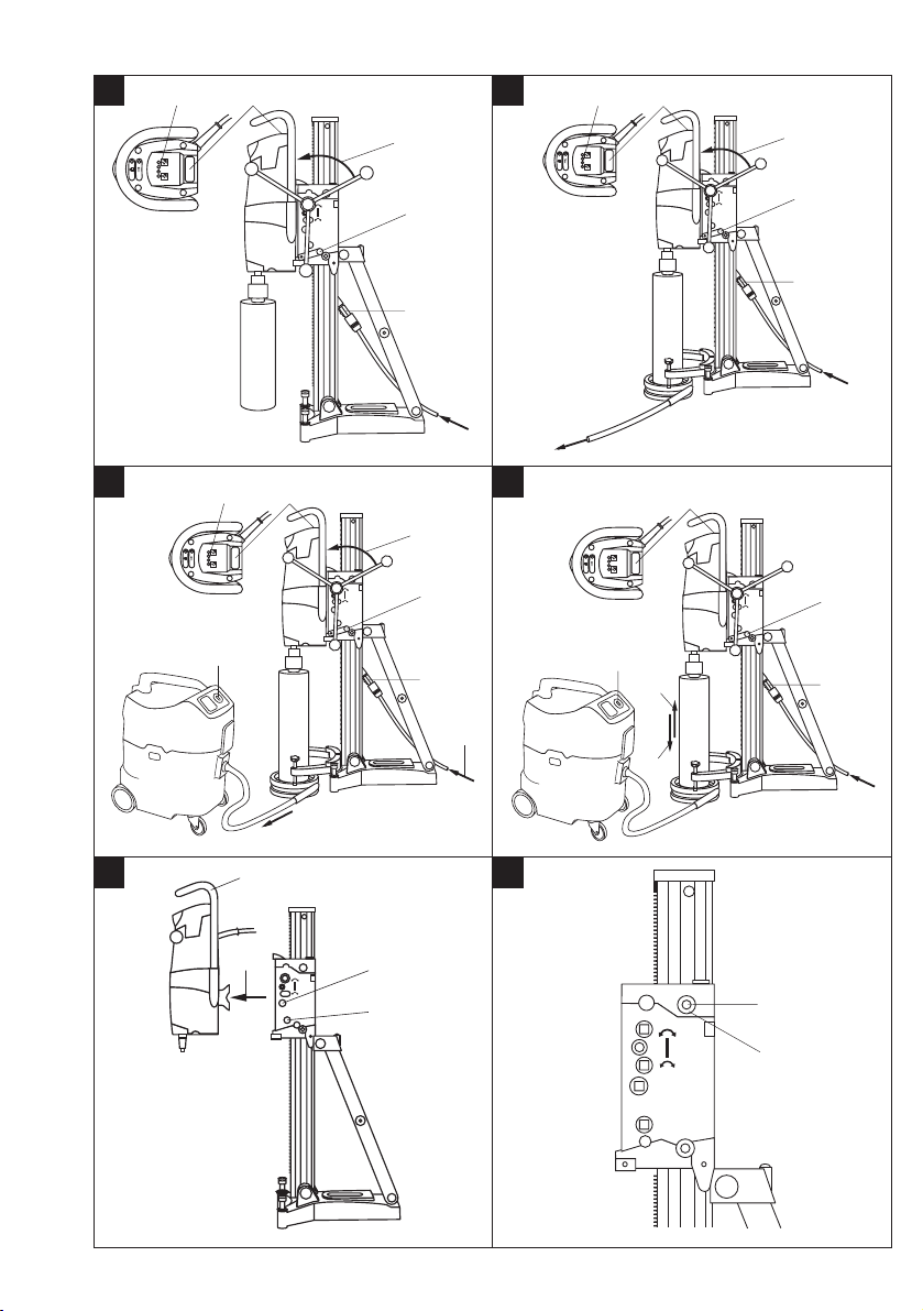
7.3 Operating the drilling machine without the water
collector system and wet vacuum cleaner
-NOTE-
The water flows away in uncontrolled fashion. Overhead
drilling is not permissible!
-CAUTION-
Do not allow water to come into contact with the drive
unit.
7.3.1 Switching on
1. Open the water flow regulator slowly until the desired
volume of water is flowing.
2. Press the on / off switch on the drive unit (switch position " I ”).
3. Release the carriage lock.
4. Turn the hand wheel until the core bit comes into contact with the material in which the hole is being drilled.
5. Apply only light pressure until the core bit has become
centered and then gradually increase the pressure.
-CAUTION-
– The machine and the core drilling operation emit noise.
Excessive noise may damage the hearing. Wear ear
protection.
– The core drilling operation may cause hazardous frag-
ments to fly off. Flying fragments may cause injury to
the eyes or other parts of the body. Wear eye protection and a hard hat.
Page 15

24
en
6. Regulate the pressure applied to the core bit by observing the drilling performance indicator (optimum drilling
performance is achieved when the green lamps in the
display light).
7.4 Operating the drilling machine with the water
collector system (accessory)
-NOTE-
The water is allowed to flow away through a length of
hose. Overhead drilling is not permissible!
-CAUTION-
Do not allow water to come into contact with the drive
unit.
7.4.1 Switching on
1. Open the water flow regulator slowly until the desired
volume of water is flowing.
2. Press the on / off switch on the drive unit (switch position " I ”).
3. Release the carriage lock.
4. Turn the hand wheel until the core bit comes into contact with the material in which the hole is being drilled.
5. Apply only light pressure until the core bit has become centered and then gradually increase the pressure.
6. Regulate the pressure applied to the core bit by observing the drilling performance indicator (optimum drilling
performance is achieved when the green lamps in the
display light).
7.5 Operating the drilling machine with the water
collector system and wet-type vacuum cleaner
(accessories)
-NOTE-
Drilling at an angle in an upwards direction is not permissible (the water collector is not functional).
The core bit fills with water during overhead drilling.
-CAUTION-
Water must not be allowed to run over the drive unit.
-NOTE-
The wet-type vacuum cleaner must be switched on manually before beginning drilling and switched off manually at the end of the drilling operation.
7.5.1 Switching on
1. Switch on the wet-type vacuum cleaner. Do not use
automatic mode.
2. Ensure that the water supply is connected and ready
for use.
3. Open the water flow regulator.
4. Press the on / off switch on the drive unit (switch position “I”).
5. Release the carriage lock.
6. Turn the hand wheel until the core bit comes into contact with the material in which the hole is being drilled.
7. Apply only light pressure until the core bit has become
centered and then gradually increase the pressure.
8. Regulate the pressure applied to the core bit by observing the drilling performance indicator (optimum drilling
performance is achieved when the green lamps in the
display light).
7.6 Switching off
1. Close the water flow regulator.
2. Withdraw the diamond core bit from the hole.
Caution: The core bit fills with water during overhead
drilling. After overhead drilling, the water must first
be allowed to drain from the core bit. This is done by
disconnecting the water supply hose from the connector on the drive unit and then opening the water
flow regulator valve (do not allow the water to flow
back through the water flow indicator). The water
must not be allowed to run over the drive unit.
3. Engage the carriage lock.
4. Switch off the drive unit.
5. Switch off the vacuum cleaner, if used.
6. To ensure that the drill stand remains in balance, lower the core bit until in contact with the working surface or fold out the hole center indicator (this is not
effective if using the vacuum baseplate).
7. If necessary, remove the core from the core bit.
7.7 Removing the drive unit from the drill stand
-NOTE-
Ensure that the machine is disconnected from the mains
supply.
1. Secure the carriage on the column by engaging the
carriage lock.
2. Hold the drive unit securely with one hand on the carrying grip. -CAUTION- The drive unit may otherwise
fall from the drill stand!
3. Release the drive unit eccentric locking bolt with the
other hand.
4. Pull out the eccentric locking bolt.
5. Remove the drive unit from the carriage.
6. Push the eccentric locking bolt back into the carriage
as far as it will go.
7.8 Disposing of drilling slurry
see Section 10 “Disposal”.
Page 16

25
en
8. Care and maintenance
Disconnect the supply cord plug from the socket.
Care of insert tools and metal parts
Remove any dirt adhering to the core bits and protect
their surfaces from corrosion by rubbing them with an
oily cloth from time to time.
8.1 Care of the machine
The outer casing of the drive unit is made from impactresistant plastic.
Never operate the drive unit when the ventilation slots
are blocked. Clean the ventilation slots carefully using
a dry brush. Do not permit foreign objects to enter the
interior of the drive unit. Clean the outside of the drive
unit at regular intervals with a cloth. Do not use a spray,
steam pressure cleaning equipment or running water
for cleaning. This may negatively affect the electrical
safety of the drive unit.
8.2 Maintenance
Check all external parts of the machine for damage at
regular intervals and check that all controls operate faultlessly. Do not operate the machine if parts are damaged
or when the controls do not function faultlessly. If necessary, the machine should be repaired at a Hilti repair
center.
Repairs to the electrical section of the machine may be
carried out only by trained electrical specialists.
8.3 Replacing the carbon brushes
The indicator lamp with the wrench symbol lights when
the carbon brushes require to be replaced.
Failure to observe the following instructions may present a possibility of coming into contact with a dangerous high voltage. The machine may be operated, serviced and repaired only by authorized, trained personnel. This personnel must be informed of any special hazards that may be encountered.
1. Disconnect the drive unit from the electric supply.
2. Remove the covers from the right and left sides of the
drive unit.
3. Remove the used carbon brushes from the drive unit.
Note how the brushes are fitted.
4. Fit the new carbon brushes exactly as the old carbon brushes (Spare part no.: 100–127 V: 279526;
220–240 V: 280097).
5. Screw the covers back on to the right and left sides
of the machine.
8.4 Adjusting play between the column and the
carriage
The play between the column and the carriage can be
adjusted by way of 4 eccentrically-mounted rollers.
The 4 rollers shown in the illustration can be adjusted.
First remove the drive unit from the drill stand and run
the carriage up to the top of the column by turning the
hand wheel. The 4 rollers can then be adjusted as follows:
1. Use a 5 mm AF hex. socket wrench to unscrew the
locking screw slightly (do not remove the screw).
2. Use a 19 mm AF open-end wrench to turn the eccentric axle, thus pushing the roller slightly toward the
column.
3. Tighten the locking screw.
8.5 Checking the equipment after care and maintenance
All functions must be checked after care and maintenance.
Page 17

26
en
9. Troubleshooting
Fault Possible cause Remedy
The machine Fault in the electric supply Plug in another electric appliance and check
doesn’t start whether it works. Check the plug connections,
electric supply, PRCD and mains fuse.
Supply cord or plug defective Have it checked by a trained electrical
specialist and replaced if necessary.
Switch defective Have it checked by a trained electrical
specialist and replaced if necessary.
Machine switched off by the automatic Have it checked by a trained electrical
cut-out carbon brushes specialist and replaced if necessary.
The motor runs Gearing defective Have the machine repaired at a Hilti service
but the core bit center.
doesn’t rotate Gear selector switch not engaged Move the gear selector switch until it is felt to
engage.
Rate of drilling Water pressure / water flow rate too high Reduce the flow with the water flow
progress decreases regulator.
Core sticks inside the diamond core bit Remove the core.
Maximum drilling depth reached Remove the core and use a core bit
extension.
Diamond core bit defective Check the core bit for damage and replace it
if necessary.
Gearing defective Have the machine repaired at a Hilti service
center.
Diamond core bit segments polished Sharpen the core bit on a sharpening plate
with water running.
Diamond core bit segments polished The wrong core bit specification has been
used. Seek advice from Hilti.
The slip clutch releases prematurely or Have the machine repaired at a Hilti service
slips permanently center.
The motor cuts out The machine stops running Reduce the pressure applied.
Electronics defective Have the machine repaired at a Hilti service
center.
Electric power failure Check the plug connections, electric supply,
PRCD and mains fuse.
Cooling fan defective Have the machine repaired at a Hilti service
center.
Carbon brushes worn Have the machine repaired at a Hilti service
center.
Water leakage at Shaft seal defective Have the machine repaired at a Hilti service
the water swivel or center.
gear housing Water pressure too high Reduce the water pressure.
The diamond core Chuck or connection end dirty or damaged Clean the connection end / chuck or replace if
bit cannot be fitted necessary.
into the chuck
Water leakage at Chuck or connection end dirty Clean the connection end / chuck.n
the chuck during
operation Core bit not screwed securely into the Tighten it securely.
chuck
Chuck seal or core bit connection end Check the seal and replace it if necessary.
defective
Page 18

27
en
Excessive play in Screw at the top end of the strut and / or Tighten the screws.
the drilling system at the column pivot point is loose
Core bit not screwed securely into the Tighten it securely.
chuck
Drive unit locking mechanism loose Tighten the drive unit locking mechanism.
Leveling screws or clamping spindle Retighten the leveling screws clamping
not tightened spindle.
Excessive play at the carriage Adjust the play at the carriage guide rollers.
Excessive play at the chuck Check that the chuck runs true and replace it
if necessary.
Connection end defective Check the connection end and replace it if
necessary.
10. Disposal
Most of the materials from which Hilti tools or machines are manufactured can be recycled. The materials must
be correctly separated before they can be recycled. In many countries, Hilti has already made arrangements for
taking back your old machines or tools for recycling. Please ask your Hilti customer service department or Hilti
sales representative for further information.
Disposal of drilling slurry
With regard to environmental aspects, allowing drilling slurry to flow directly into rivers, lakes or the sewerage
system without suitable pre-treatment is problematical. Ask the local authorities for information about applicable regulations.
We recommend the following pre-treatment:
Collect the drilling slurry (e.g. use a wet-type industrial vacuum cleaner).
Allow the slurry to settle and dispose of the solid material at a construction waste disposal site (the addition of
a flocculent may accelerate the settling process).
Water from the drilling slurry (alkaline, ph value > 7) should be neutralized by adding an acidic neutralizing agent
or large quantity of water before it is allowed to flow into the sewerage system.
Only for EU countries
Do not dispose of electric tools together with household waste material!
In observance of European Directive 2002/96/EC on waste electrical and electronic equipment
and its implementation in accordance with national law, electric tools that have reached the
end of their life must be collected separately and returned to an environmentally compatible
recycling facility.
Page 19

28
en
12. EC declaration of conformity
We declare, on our sole responsibility, that this product
complies with the following standards or standardization documents: 98/37/EC, 89/336/EEC, EN 55014-1,
EN 55014-2, EN 61000-3-2, EN 61000-3-3, EN 61029-1.
Designation: Diamond drilling system
Type: DD 200
Year of design: 2003
Hilti Corporation
Dr. Ivo Celi Dr. Heinz-Joachim Schneider
Senior Vice President Executive Vice President
Business Unit Diamond Business Area Electric Tools & Accessories
12/2004 12/2004
11. Warranty
Hilti warrants that the product supplied is free of defects
in material and workmanship. This warranty is valid as
long as the product is operated and handled correctly,
cleaned and serviced properly and in accordance with
the Hilti operating instructions, all warranty claims made
within 6 months (machine) or 12 months (other items
of equipment) from the date of the sale (invoice date),
unless other mandatory national regulations prescribe
a longer minimum period, and the technical system is
maintained. This means that only genuine Hilti consumables, components and spare parts may be used
with the product.
This warranty provides the free-of-charge repair or
replacement of defective parts only. Parts requiring repair
or replacement as a result of normal wear and tear are
not covered by this warranty.
Additional claims are excluded, unless stringent national rules prohibit such exclusion. In particular, Hilti is
not obligated for direct, indirect, incidental or consequential damages, losses or expenses in connection
with, or by reason of, the use of, or inability to use the
product for any purpose. Implied warranties of merchantability or fitness for a particular purpose are
specifically excluded.
Send the product and/or related parts immediately upon
discovery of a defect to the local Hilti marketing organization for repair or replacement.
This constitutes Hilti's entire obligation with regard to
warranty and supersedes all prior or contemporaneous
comments and oral or written agreements concerning
warranties.
Page 20

Hilti Corporation
FL-9494 Schaan
Tel.: +423/ 234 2111
Fax: +423 /2342965
www.hilti.com
Hilti = registered trademark of Hilti Corp., Schaan W 2936 0105 50-Pos. 1 1 Printed in Liechtenstein © 2005
Right of technical and programme changes reserved S. E. & O.
305560 / D
 Loading...