

Page 1

DD-160 E
Diamond Core Coring System
Operating Instructions
2–8
Système de carottage au diamant
Mode d’emploi
9–15
Sistema de taladro con diamante
Manual de instrucciones
16–22
Sistema de perfuração com coroa diamantada
Manual de Instruções
23–29
*236036*
236036
Page 2
2
Safety precautions
Contents Page
1. DD-160 E
diamond coring system 2
2. DD-160 E
diamond coring rig 3
3. Safety 3
4. Technical data 4
5. Assembling the system
components 4
6. Selecting the method of
fastening the coring rig 5
7. Preparing the coring system
for use 5
8. Operating the system 8
9. Maintenance 8
10. Warranty 8
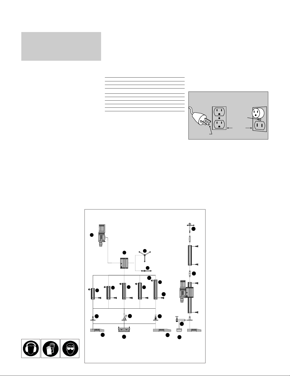
1. The DD-160 E diamond coringsystem
1.DD-160 E motor unit
2.DD-CA-S carriage
3.Handwheel DD-FH
1
/2’’
4.Ratchet
1
/2’’
5.DD-R 80-S rail
6.DD-R 100-S rail
7.DD-R 120-S rail
8.DD-R 65 F-S rail
9.DD-R 100 F-S rail
10.DD-CO-S taper
11.DD-EP-S eccentric pin
12.DD-SL-SML spindle
13.DD-CP-S stop
14.DD-BA-3 baseplate
15.DD-BAV-4 baseplate
16.DD-BV-P baseplate
17.DD-BCQ-S baseplate taper
18.DD-BCS-S baseplate taper
19.DD-BCR-S baseplate taper
20.DD-WC-SM water collector
21.DD-HSM-S holder
Do not use thisproduct in any
way other than asdirected by these
operating instructions.
Always wear ear
protectors.
Always wear
protective gloves.
Always wear safety
glasses.
for grounded tools
Read all instructions
Warning!
The following fundamental safety pr ecautions must
always be observed when using electric tools/machines
as protection against an electric shock, the risk of injury
and a fire hazard.Please readand takenote of these precautions before you use the tool/machine. Please read
and keep these safety precautions ina safe place!
1. Keep Work Area Clean. Cluttered areas and benches invite
injuries.
2. Consider Work Area Environment. Don’t expose power
tools to rain. Don’t usepowertoolsindamporwetlocations.Keep
work area well lit. Do not use tool in presence of flammable liquids
or gases.
3. Guard Against Electric Shock. Prevent body contact with
grounded surfaces. For example; pipes, radiators, ranges, refrigerator enclosures.
4. Keep Children Away. Do not let visitors contact tool or extension cord. All visitors should be kept away from work area.
5. Store Idle Tools. When not in use, tools should be stored in
dry,and high or locked-up place – out of reach of children.
6. Don’t Force Tool. It will do the job better and safer at the rate
for which it was intended.
7. Use Right Tool. Don’t for ce small tool or attachment to do the
job of a heavy-duty tool. Don’t use tool forpurpose not intended –
for example – don’t use circular saw for cutting tree limbs or logs.
8. Dress Properly. Do not wear loose clothing or jewelry. They can
be caught in moving parts. Rubber gloves and non-skid footwear
are recommended when working outdoors. Wear protective hair
covering to contain long hair.
9. Use Safety Glasses. Also use face or dust mask if cutting operation is dusty.
10. Don’t Abuse Cord. Never carry tool by cord or yank it to disconnect from receptacle. Keep cord from heat, oil, and sharp
edges.
11. Secure Work. Use clamps or a vise to hold work. It’s safer
than using your hand and it frees both hands to operate tool.
12. Don’t Overreach / Maintain Control. Keep proper footingand
balance at all times.
13. Maintain Tools With Care. Keep tools sharp and clean for better and safer performance. Follow instructions for lubricating and
changing accessories. Inspect tool cords periodically and if damaged, have repaired by authorized service facility. Inspect extension cords periodically and replace if damaged. Keep handles dry,
clean, and free from oil and grease.
14. Disconnect Tools. When not in use, before servicing and
when changing accessories, such as blades, bits, cutters.
15. Remove Adjusting Keys and Wrenches. Formhabit of checking to see that keys and adjusting wrenches are removed from tool
before turning it on.
16. Avoid Unintentional Starting. Don’t carry tool with finger on
switch. Be sure switch is off when plugging in.
16A. Extension Cords. Make sure your extension cord is in good
condition. When using an extension cord, be sure to use one
heavy enough to carry the current your product will draw. An
undersized cord will cause a drop in line voltage resulting in loss
of power and overheating. The following table shows the correct
size to use depending on cord length and nameplate ampere rating. If in doubt, use the next heavier gage. The smaller the gage
number,the heavler the cord.
Extension Cord Table
Volts TotalLengthofCordinFeet
120 V 0–25 26– 50 51–100 101–150
240 V 0–50 51–100 101–200 201–300
Ampere Rating AWG
More Than Not More Than
0 6 18 16 16 14
610 18161412
10 12 16 16 14 12
12 16 14 12 Notrecommended
17. Outdoor Use Extension Cords. When tool is used outdoors,
use only extension cords intended for use outdoors and so
marked.
18. Stay Alert. Watch what you are doing. Use common sense.
Do not operate tool when you are tired.
19. Check Damaged Parts. Before further useof the tool, aguard
or other part that is damaged should be carefully checked to determine that it will operate properly and perform its intended function. Check for alignment of moving parts, binding of moving
parts, breakage of parts, mounting, and any other conditions that
may affect its operation. A guard or other part that is damaged
should be properly repaired or replaced by an authorized service
center unless otherwise indicated elsewhere in this instruction
manual. Have defective switches replaced by authorized service
center.Do not use tool if switch does not turn it on and off.
20. Only use accessories and attachments which are given in the
operating instructions or in the respective catalogue. The use of
accessories or insert tools or attachmentsother than those speci-
fied in the operating instructions can result in personal injury to
you.
21. Only have repairs carried out by recognized electrical specialists. This electric tool/machine complies with respective safety
regulations. Repairs may only be carried out by an electrical specialist otherwisean accident hazard for the operator can exist.
22. Wear ear protectors when using for extended periods.
23. Always use any supplied side handle, and keep it tightly
secured; use both hands during operation. Firmcontrol of the tool
is necessaryshould the tool bind.
24. Hold Tool by Handle(s) Provided. Do not touch uninsulated
parts of tool when drilling. Exposed metal surfaces may be made
live if the tool drills into electrical wiring.
25. Grounding instructions. This tool should be grounded while in
use to protect the operator from electric shock. The tool is
equipped with a 3-conductor cord and 3-prong grounding type
plug to fit the proper grounding type receptacle. The green (or
green and yellow) conductor in the cord is the grounding wire.
Never connect the green (or green and yellow) wire to a live terminal. If your unit is for use on less than 150 V, it has a plug that
looks like that shown in sketch (A) in Figure «Grounding Methods». An adapter, see sketch (B), is available for connecting sketch
(A) type plugs to 2-prong receptacles. Thegreen-colored rigid ear,
lug, or the like, extending from the adapter must be connected in a
permanent ground, such as a properly grounded outlet box.
GROUNDING METHODS
metal screw
cover of grounded
grounding pin
26. Extension Cords. Use only 3-wire extension cords that have 3prong grounding-type plugs and 3-pole receptacles that accept the
tool’splug. Replace or repair damaged cords.
27. Replacement parts. When servicing use only identical
replacement parts.
Save these instructions.
(A)
outlet box
(B)
1
DD-160-E
2
DD-CA-S
DD-R 100-S
DD-BV-P
16
6
18
8
DD-R 65F-S
17
DD-BCQ-S DD-BCS-S DD-BCR-S DD-BCQ-S
DD-BA-3 DD-BAV-4
5
DD-R 80-S
14
DD-R 100F-S
3
DD-CP-S
9
12
4
13
7
11
DD-R 120-S
DD-EP-S
19
DD-HSM-S
10
DD-CO-S
DD-CA-S
21
DD-WC-SM
15
20
DD-BA-3
Page 3
3
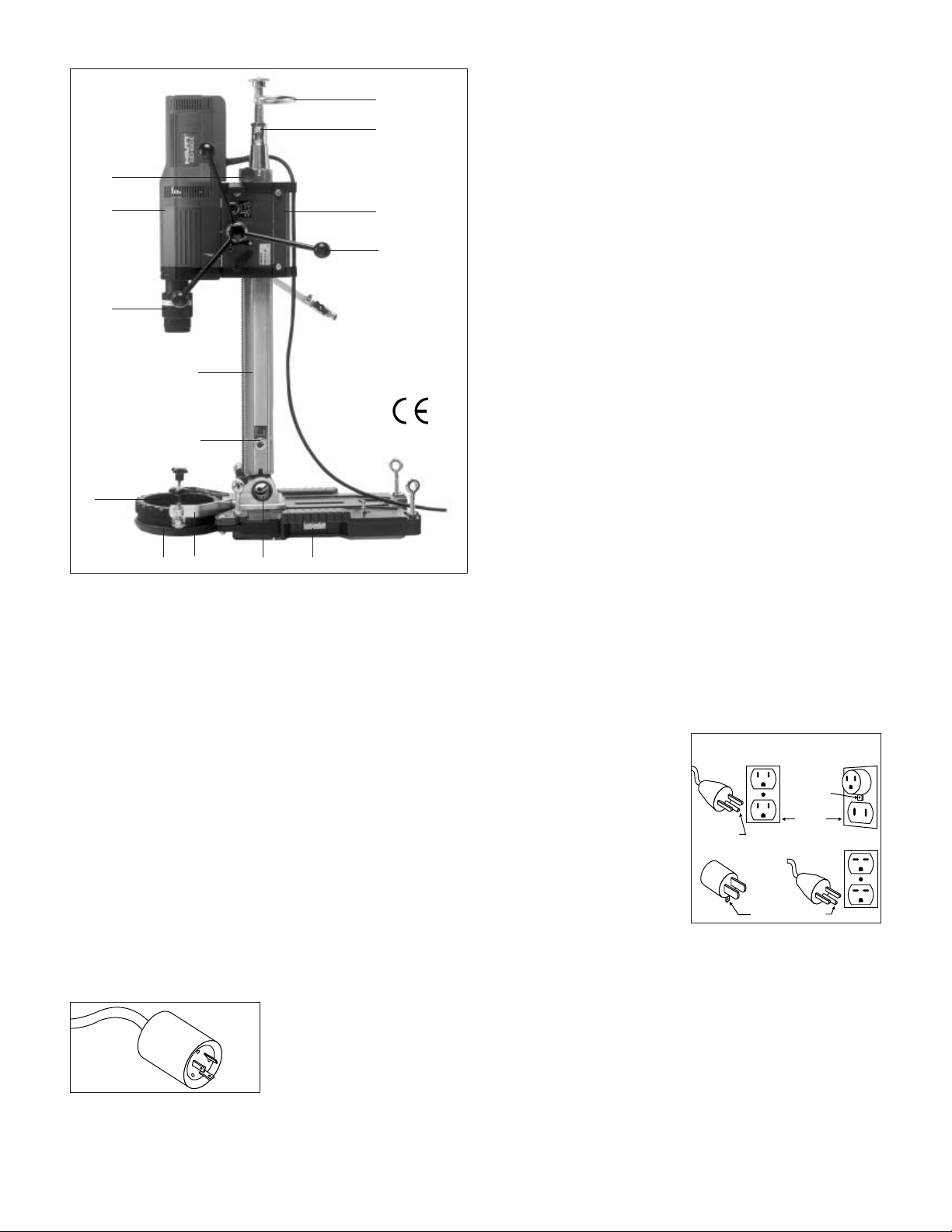
2. DD-160 E diamondcoring rig
1.DD-160 E motor unit
2.DD-C-BU chuck
3.DD-CA-S carriage
4.DD-FH
1
/2” handwheel
5.DD-R 100-S rail
6.DD-CO-S taper
7 .DD-SL-SML spindle
8.DD-CP-S stop
9.DD-EP-S eccentric pin
10.DD-BCS-S baseplate taper
11.DD-BAV-4 baseplate
12.DD-HSM-S holder
13.DD-WC-SM water collector
14.DD-SW-SM sealing disc
3. Safety
3.1 Safety precautions onthe jobsite
Before beginning work withthe coring
system, read the operatinginstructions carefully and ensurethat the
safety precautions listed beloware
observed.
Please also note thatpermission to
begin coring work mustbe obtained
from the site engineeror other authorised person.
■ Ensure that no electriccables, gas
or water pipes etc.are situated
where holes are tobe drilled.
■ Cables, pipes or othersupply lines
situated in close proximityto where
holes are to bedrilled must be
switched off.
■ The coring work mustnot have a
negative effect on thestructural design of the building(coring through
steel reinforcement!).
■ Cordon off areas wherecoring work
is taking place, particularlybehind/
below walls or ceilingswhich are
being drilled through.
■ Wear a helmet, safetyshoes, gloves
and ear protectors.
■ Tidiness and good organisation
on the jobsite helpto prevent accidents.
■ Use only original Hilti parts.
■ Protect the motor unitfrom water
spray and rain.
■ For overhead coring, thewater col-
lector and water removalsystem
must be in goodorder and function
correctly.
쐃
쐇
쐄
쐎
쐉씈쐈쐅
쐊
쐏
쐋
쐂
쐆
씉
3.2a Grounding instructions
This tool should begrounded while
in use to helpprotect the operator
from electric shock. Thetool is equipped with a 3-conductorcord and
3-prong grounding type plugto fit the
proper grounding type receptacle.The
green (or green andyellow) conductor
in the cord isthe grounding wire.Never connect the green(or green and
yellow) wire to alive terminal.
If your unit isfor use onless than
150V, it hasa plug thatlooks likethat
shown in sketch (A)in Figure 1.If itis
for use on 150to 250 V,it hasa plug
that looks like thatshown in sketch
(D). An adapter, seesketches (B) and
(C), is available forconnecting sketch
(A) type plugs to2-prong receptacles.
The greencolored rigid ear,lug, or the
like, extending from theadapter must
be connected to apermanent ground,
3.2b Extension Cords
Use only 3-wire extension cords that
have 3-prong grounding-type plugs and
3-pole receptacles that accept the tool’s
plug. Replace or repair damaged cords.
such as a properlygrounded outlet
box. No adapter isavailable for aplug
as shown in sketch(D).
metal screw
cover of grounded
outlet box
grounding pin
grounding
means
grounding pin
GROUNDING METHODS
(A)
(B)
(C) (D)
For the DD-160Ea20Aplug is
demanded that looks likethat shown
in Figure 2.
Figure 2
Figure 1
■ The coring system mustonly be
operated with the built-inGFCI
ground fault circuit interruptor.
■ In order to ensuresafe, trouble-free
operation, the drilling systemmust
be kept clean.
(Do not clean usinga jet ofwater.)
■ Drilling work should onlybe carried
out by trained personnel.
■ When working with thevacuum
baseplate on walls anadditional
means of securing therig must be
employed (see section 7.2).
■ If leakage occurs inthe water
supply system, the equipmentmust
be serviced.
■ Do not touch rotating parts.
3.2 Electrical safety
The GFCI ground faultcircuit interruptor protects the operatorin case of
faults in the insulationof the motorunit
or supply cord (betweenthe GFCI and
the motor unit). Thisdevice also prevents the machine fromrestarting on
its own accord whenpower returns
after an interruption inthe power supply. The earth/ground connectionprotects the operator fromdangerously
high voltages in caseof coring intolive
cables. The protective functionof the
ground fault interrupter mustbe
checked at regular intervalsin accordance with regulations issuedby
national authorities (see section7.17).
3.3 Overload protection
Hilti diamond coring systemsare
equipped with mechanical, electronic
and thermal overload protectiondevices.
Mechanical clutch:
Protects the operator, motorand core
bit in case thecore bit suddenlysticks.
Electronic protection:
In case of overloadingcaused by
excessive coring feed pressure,motor
current is reduced automaticallyso
that the core bitthen only rotates
slowly. Motor current returnsto normal when coring feedpressure is
reduced, and the motorthen continues to run atfull power.
Protection against overheating:
The motor is protectedagainst overheating by a sensorwhich auto-matically reduces current inputin case of
sustained overloading and athigh
ambient temperatures. The machine
can be operated normallyafter the
temperature of the motorwindings
has dropped to asatisfactory level.
The motor windings canbe cooled
more quickly by allowingthe motor to
run without load.
Page 4

4
3.4 Instructions andprecautions for overhead coring
When coring overhead, forsafety
reasons, the following equipment
must be used:
1 .Baseplate, fastened tothe ceiling
using an HDI
1
/2˝ anchor.
2.Water collector complete with
appropriate sealing disc.
3.Hose strain-relief clamp.
4.Water removal hose.
5.Adaptor for vacuum cleaner.
6.6 mA GFCI groundfault circuit
interruptor
(integral part of supplycord).
7.Supply cord with earth/ground
conductor.
8.Vacuum cleaner suitable forwet
materials.
9.Three-way water connection.
10.Rail stop
Turn off the watersupply and drainthe
water from the corebit at thethreeway water connector beforewithdrawing the core bit.
Note: The life ofthe sealing discscan
be extended by applyinga little grease
(e.g. bearing grease) orHilti lubricant
spray.
4.Technical data
Voltage 115 V 230 V
Current input 18 A 9A
Power input 2000 W 2000 W
Frequency 50/60 Hz
Core bit diameter range 25 – 162 mm
Core bit diameter range: Speeds (no load):
1st speed: 500 r.p.m. 92 – 162mm dia.(3
5
/9”–63/8”)
2ndspeed: 1000 r.p.m. 40 – 102 mm dia.(1
1
/2” – 4”)
3rd speed: 2000 r.p.m. 25 – 52mm dia.(1” – 2”)
Weight (motor unit) 11.5 kg
Length of supply cord 5metres
Chuck DD-C-BU quick-release chuck
Electronic idling speed regulator
Overload current regulator
Optical service indicator
Built-in starting current regulator
Thermal motor overload protection
Mechanical slip clutch
Protection class I, withinternal class IIdesign (mainssupply with earth/ ground
connection required)
Ground fault circuit interruptor(GFCI) 6 mA 30 mA
Zero-voltage trip
Approved as per IEC1029
Noise and vibration
TechnicalA-weighted noiselevels of themachineare:
– Noise (pressure) level 89 dB (A)
– Noise (power) level 102 dB(A)
Ear protection must beworn.
Typical exposure of thehand/arm to vibrationis lessthan 2.5 m/s
2
.
Right of technical modificationsreserved.
5. Assembling the system components
5.1 Mounting thebaseplate taper on the baseplate
1. Baseplate
2. Baseplate taper
3. Mounting screws (4)
4. Wrench (supplied withthe
baseplate)
5.2 Fitting thewheel assembly to the baseplate
1. Baseplate
2. Wheel
3. Screw
4. 19 mm AFwrench
5.4 Changing thechuck
1. Drive shaft
2. Chuck
3. Screws (2)
4. 6 mmAF wrench
(supplied with the chuck)
5.3 Fitting thewater collector holder to thebaseplate taper
1. Baseplate taper
2. Holder
3. Screw
4. 8 mmAF wrench
(supplied with the holder)
This Product is UL listed and CSA certified
R
3
2
1
4
7
5
8
6
10
9
2
1
3
4
1
3
2
4
4
3
2
1
1
4
O
P
E
N
3
E
S
O
L
C
2
Page 5

5
6. Selecting the method offastening the coringrig
6.1 Anchor fastening
– Secure method of fasteningfor high
coring performance
– Versatile method
(Suitable for use onwall, ceiling
or floor)
– Can also be usedon unevenand
rough surfaces
Caution: The coring system must not
be operated before the rig hasbeen
secured rigidly in position!
6.3 Braching usingthe guide rail
– Quick method
– No need to drillanchor holes
– Very rigid
– Can be used inaddition toanchor
fastening or with thevacuum baseplate
Bracing using the guiderail is notsuitable for overhead applications.
Caution: The coring system must not
be operated before the rig hasbeen
secured rigidly in position!
– Quick method
– No need to drill anchorholes
Caution: Must be securedadditionally
for wall applications withchain, rope,
brace or support tosupport a loadof
at least 400 kg.
For ceiling applications isthe use ofa
vacuum baseplate not allowed.
The coring system mustnot be
assembled or operated beforethe rig
has been rigidly securedin position.
6.2 Fastening the unitusing the vacuumbaseplate
6.4 Bracing using thequick-release column
– Quick and simple method
– No need to drill anchorholes
– Can be used in additionto anchor
fastening and with thevacuum
baseplate
Bracing using the quick-releasecolumn is not suitablefor overhead applications.
Caution: The coring systemmust
not be operated beforethe righ has
been secured rigidly inposition!
7. Preparing thecoring system for use
7.1 Fastening the baseplate using ananchor andbracing spindle
7.1a Fasteningthe baseplateusing an anchorand bracingspindle
(continued)
1 .Tighten the levelling screws(in diag-
onal sequence) until thebaseplate
stands rigidly and securely.
7.2 Securing the vacuum baseplate
1. Vacuum pump
2. Vacuum connection
3. Vacuum plate
4. Hand grips
5. Release valve
6. Centre indicator
7. Vacuum gauge
(indicator must remain withingreen
area while baseplate isin use)
8. Levelling screws
9. Securing chain,rope, brace or
support (see section 6.2.)
Raise the levelling screwsand check
the seal for damagebefore positioning
the vacuum baseplate.
7.2a Securingthe vacuumbaseplate (continued)
1. After applyingthe vacuum, tighten
the levelling screws byhand, as far
as they will go,following a diagonal
sequence.
1. HDI1/2˝ internally-threaded
anchor (in concrete)
2. Bracing spindle
3. Baseplate
4. Hole-centre indicator
5. Bracing spindlenut
6. Open-end wrench
The coring rig ismost stable whenthe
anchor is positioned atthe front endof
the anchor slot (closestto column).
Recommended distance from anchor
to hole centre -approx. 300 mm.
Raise the levelling screwsbefore positioning the baseplate.
3
2
1
4
5
6
1
9
7
4
5
3
6
2
8 1
Page 6

6
7.3 Bracing the baseplate using thequick-release column
1. Baseplate
2. Quick-release column
3. Telescopie column
4. Bracing mechanism
7.4 Mounting a rail on thebaseplate
1. Connecting taper
2. Rail
3. Eccentric pin
4. Wrench
7.5 Mounting the carriage on therail
1. Carriage
2. Rail
3. Feed movementlocking device
The feed movement lockingdevice
must face the directionof coring.
7.6 Fittingthe stopon the rail
1. Rail
2. Steel bar
3. Engaging teeth
4. Clamping screw
The use of astop is mandatoryfor
coring overhead and onwalls.
7.7 Adjustingthe railangle
1. Baseplate
2. Baseplate taperfor angular coring
3. Clamping screw
4. Wrench
Secure the rig sothat it cannotfall
before releasing the clampingscrew.
Angular coring in anupwards direction
is not permitted (watercollector does
not function correctly).
7.8 Extending theguide rail
1. Rail
2. Rail extension
3. Taper
4. Eccentric pins(2)
5. Wrench
7.9 Fitting the bracing spindle
1. Rail
2. Eccentric pin
3. Wrench
4. Taper
5. Spindle
6. Locking nut
7.10 Mounting the motor unit on thecarriage
1. Motor unit
2. Motor unit mount
3. Carriage
4. Mounting surface
5. Eccentric clampingpin
6. Wrench
7. Supply cordsupport
8. Water hosesupport
Caution: Do not pinchthe supply
cord!
Removing the motor unit:Hold the
motor to prevent itfrom falling when
the eccentric clamping pinis pulled
out.
3
4
2
4
3
2
1
1
3
2
2
1
3 4
1
45˚
2
4
3
1
5
6
4
1
2
3
2
4
3
5
1
2
4
1
7
3
5
6
8
Page 7

7
7.11 Fitting the handwheel
1. Carriage
2. Connecting boss
3. Handwheel
4. Clamping screw
The handwheel can befitted on either
side.
7.12 Fitting a core bit
1. Chuck
2. Connection end
3. Core bit
4. Locking sleeve
5. Motor unit
7.13 Releasing a core bit
1. Chuck
2. Core bit
3. Locking sleeve
Hold the core bitbefore disengaging
the chuck.
When releasing the corebit, ensure
that the core doesnot fall outaccidentally.
After overhead coring, drainthe core
bit through the watersupply hose
before releasing it fromthe chuck (see
section 3.4).
7.14 Inserting a sealing disc in thewater collector
1. Water collector
2. Sealing disc
(select correct diameter)
3. Clamping ring
4. Hose connection
5. Sealing ring
6. Water removalhose
A water removal systemand a sealing
disc in new conditionmust always be
used for overhead coring.
Sealing discs of thecorrect diameter
are available from yourlocal Hilti
centre or representative.
7.15 Fitting the water collector
1. Baseplate
2. Water collector holder
3. Water collector
4. Clamping screws
Use the core bitto centre thewater
collector and then tightenthe clamping screws evenly.
Use of the watercollector is mandatory for overhead coringand recommended for all othercoring positions.
7.16 Connecting the water supply
1. Carriage
2. Hose support
3. Water hose
4. Water regulationvalve
5. Hose connector
6. External watersupply
The water supply pressuremust not
exceed 10 bar.
7.17 Connecting to the mains supply
(Mains socket with earth/ ground connectionrequired)
1. Plug – typedepends on country
2. GFCI groundfault circuit interruptor
3. ON-switch forGFCI
4. Test button
5. Indicator
6. Supply cord
7. Motor unitON / OFFswitch
The GFCI must betested for correct
operation each time beforebeginning
work.
1. Check that themotor is switched off.
2. Connectthe plug to the mains supply.
3. Press theON button. Thelamp
must light!
4. Press theTEST button. Thelamp
must extinguish!
5. Press theON button againbefore
beginning operation.
In the case ofa malfunction (test
failed), the unit mustbe checked by
an electrical specialist beforework
with the equipment continues!
After every fault orinterruption in the
mains supply, switch offthe motor unit
before resetting the GFCIinterruptor.
1
2
3
4
5
1
4
2
3
O
S
P
O
E
L
N
C
1
2
1
E
3
2
4
56
3
2
1
3
4
1
2
3
4
5
6
7
6
3
5
2
4
1
6
Page 8

8
8. Operation
1. Select thecorrect coring speed.
(Change speed only whenrotation
has stopped.)
2. Release thefeed movement locking
device.
3. Guide thecore bit intothe water
collector.
4. Open thewater supply valve.
5. Switch onthe motor.
(When using a vacuumbaseplate,
ensure that the vacuumindicator
remains within the greenarea.)
■ Reduce feed pressure whenstart-
ing holes in orderto avoid vibration.
■ If steel reinforcement iscontacted,
select lower coring speedif possible and reduce waterflow.
(Obtain permission from anauthorised person before cuttingthrough
steel reinforcement.)
■ The diamond segments canbe-
come polished (reduced cutting
performance) if coring feedpressure is too lowor if thewater flow
rate is excessive.
■ Insufficient water will causeover-
heating, resulting in seriousdamage to the corebit.
■ Reduce coring feed pressureif
the overload current regulatoris
activated.
■ Water flow rates
8 – 47mm dia. max. 1–1.5 l/min.
52 –132 mmdia. max.3 l/min.
142 –162 mmdia. max. 4l/min.
9 Maintenance
9.1 In orderto ensure trouble-free operation, thefollowing points must be
observed:
1 Motor unit
■ Keep the chuck cleanand well
lubricated.
■ Keep the ventilation slotsin the
motor housing free ofdirt and dust.
■ If the service indiciatorlights, the
carbon brushes must bereplaced
by a trained specialistas soon as
possible.
■ Check the system regularlyfor
water leakage.
2 Carriage
■ The guide rollers requireno mainte-
nance.
■ Keep the motor unitmounting sur-
face clean.
■ If movement is tooeasy, the guide
rollers should be adjustedby a
trained specialist.
3 Rails
■ Keep the rails clean
■ Internal tapers must bekept clean
and lightly oiled.
4 Baseplate
■ With the exception ofthe seals, the
baseplates require no maintenance.
9.2 Wearing parts
■ Seals for the DD-BAV-4and
DD-BV-P vacuum baseplates
■ Sealing discs for theDD-WC-SM
water collector
■ Sealing ring for theDD-WC-SM
water collector
Sealing discs of thecorrect diameter
are available from yourlocal Hilti centre or representative.
In case of technicalproblems
please contact the Hilticustomer
service department.
Tips
➌
➎
➌➍➊
➋
10. Warranty
Hilti warrants that the tool supplied is
free of defects in material and workmanship. This warranty is valid so
long as the tool is operated and handled correctly, cleaned and serviced
properly and in accordance with the
Hilti Operating Instructions, all warranty claims are made within
6 months for the motor unit and
1year for additional equipment and
accessories from the date of the sale
(invoice date), and the technical system is maintained. This means that
only original Hilti consumables, components and spare parts may be
used in the tool.
This warranty provides thefree-ofcharge repair or replacementof defective parts only. Partsrequiring repair or
replacement as a resultof normal
wear and tear arenot covered bythis
warranty.
Additional claims are excluded,
unless stringent national rulesprohibit such exclusion. Inparticular,
Hilti is not obligatedfor direct, indirect, incidental or consequential
damages, losses or expensesin
connection with, or byreason of,
the use of, orinability to usethe tool
for any purpose. Impliedwarranties
of merchantability or fitness for a
particular purpose are specifically
excluded.
For repair or replacement,send tool
and/or related parts immediatelyupon
discovery of the defectto the address
of the local Hiltimarketing organization
provided.
This constitutes Hilti’s entireobligation
with regard to warrantyand supersedes all prior orcontemporaneous
comments and oral orwritten agreements concerning warranties.
Page 9

USA
Hilti, Inc.
5400 South 122
nd
East Avenue
Tulsa, Oklahoma 74146
Telephone (918)252-6000
CANADA
Hilti (Canada) Limited /Limitée
6790 Century Avenue, Suite300
CDN - Mississauga, OntarioL5N2V8
Telphone (905) 8139200
LATIN AMERICA
Hilti Latin America, Ltd.
5400 South 122
nd
East Avenue
P.O. Box 21148
Tulsa, Oklahoma 74146
Telephone (918)252-6595
Hilti = registered trademark of Hilti Corp., Schaan W 1950 0802 10-Pos. 3 1 Printed in Liechtenstein © 2002
Right of technical and programme changes reserved S.E.&O.
236036/F
 Loading...