

Page 1

DD130
Bedienungsanleitung 1–12
Operating instructions 13–24
*370458*
370458
D
GB
F
I
NL
P
E
DK
SF
N
S
TR
EST
LV
LT
Page 2
35
39
34
3231 33
53 52 51
50
38
37
40
36
28
29
27
25
26
24
23
30
41
42
43
46
57
56
55
54
45
44
47
48
49
DD 130
12
13
14
113
15
1617
18
21 1922
1098652 41 7
20
1
Page 3
DD 130
6.1.1
DD 130
1
4
3
2
15∞
15∞
15∞
15∞
15∞
15∞
6.1.3
1
2
3
6.4.1
DD 130
1
2
6.6.2
DD 130
1
1
6.1.2
1
4
2
5
3
6.2
2
3
1
6.5.1
1
2
4
3
7
5
6
6.7.1
DD 130
2
3
6.1.2
1
1
6.3
DD 130
4
1
3
2
6.6.1
2
6
3
1,4
5
6.7.2
Page 4
1
2
6
4
5
3
6.7.3
1
2
6.10
1
7.2.1
1
5
4
90˚
0
1
2
2
3
7.4
1
5
2
4
3
6
6
7
6.8
4
5
3
1
2
6.11
1
2
4
3
4
7.2.2
1
0
1
2
3
7
2
4
5
6
7.5
1
DD 130
2
3
5
4
6.9
2
3
4
5
4
1
6.12
3
4
1
1
90˚
2
7.3
3
2
1
2
1
8.5.1.1
2
1
8.5.1.2
Page 5

13
It is essential that the operating
instructions are read before the
tool is operated for the first time.
Always keep these operating
instructions together with the tool.
Ensure that the operating instructions are with the tool when it is
given to other persons.
Contents Page
1. General information 14
2. Description 14
3. Tools and accessories 14
4. Technical data 15
5. Safety precautions 15
6. Before use 17
7. Operation 20
8. Care and maintenance 21
9. Troubleshooting 22
10. Disposal 23
11. Warranty 23
12. Declaration of conformity see cover
DD1 30 diamond core drilling machine
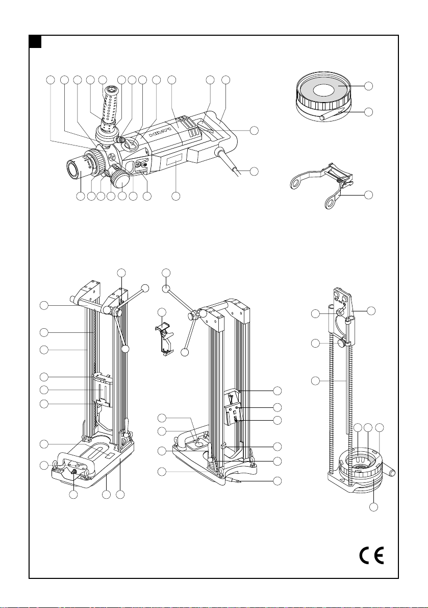
Parts of the DD130
Core drilling machine
Water swivel / extraction head
Water flow indicator
Level indicator
Screwdriver (side handle)
Side handle
Water flow regulator
Water hose connector
Gear selector
Gearing section
Motor
On / off switch
Grip
Overload indicator
Supply cord with PRCD
Rating plate
Interface plate
Screw plugs (water swivel / extraction head)
Cover (water swivel / extraction head)
Extraction connector
Water swivel lock
Locking ring (water swivel / extraction head)
Chuck
Drill stand
Grip
Chain
Columns
Hex. wrench
Carriage
Release lever
Specification plate
Vacuum release valve
Vacuum hose connector
Vacuum pad
Baseplate
Chain arrestor
Hand wheel
On / off switch lock
Pressure gauge
Level indicator
Adjusting lever
Levelling screws
Hole centre indicator
Locating lugs
Depth gauge
Locking mechanism
Mounting pins
Chain tensioner
Water collector for hand-held use
Securing knob
Clamping screw
Depth gauge
Water collector cup
Centring ring
Centring ring adaptor
Seal
Mounting plate
Water collector for use with the drill stand
Holder
Water collector cup
Seal
21
22
23
24
25
26
27
28
29
30
31
32
33
34
35
36
37
38
39
40
41
42
43
44
45
46
47
48
49
50
51
52
53
54
55
56
57
Page 6
14
General
warning
Warning:
electricity
Warning: hot
surface
Obligation signs
Symbols
On the drill stand On the tool
Wear eye
protection
Wear a safety
helmet
Wear ear
protection
Wear safety
gloves
Wear safety
boots
1. General information
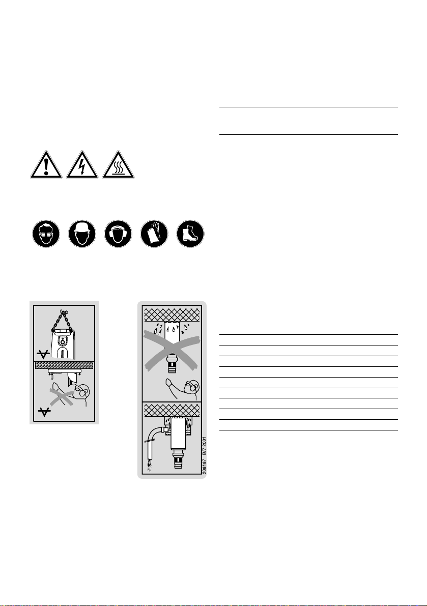
1.1 Indication of danger
-CAUTION-
Used to draw attention to a potentially dangerous situation which could lead to minor personal injury or damage to the equipment or other property when the given
safety precautions are not observed.
1.2 Pictograms
Warning signs
VACUUM
VACUUM
Top
An additional means of securing the drill stand must be
employed when used for horizontal drilling with vacuum
attachment.
Bottom
The drill stand must be fastened by means of an anchor
or quick-release brace when
used for overhead drilling.
Use of the water collector
system in conjunction with a
wet-type vacuum cleaner is
mandatory when working
overhead on ceilings.
Location of identification data on the tool
The type designation and serial number can be found
on the rating plate on the tool. Make a note of this data
in your operating instructions and always refer to it when
making an enquiry to your Hilti representative or service department.
Type: DD130
Serial no.:
2. Description
The DD 130 is an electrically powered diamond core
drilling machine designed for hand-held use or for mounting on a drill stand. It is suitable for wet or dry core
drilling.
Items supplied
The items supplied are: core drilling machine and operating instructions.
3. Accessories
Designation Item no.
Vacuum pump 47034
Quick-release brace 9870
Water collector system for hand-held use 370462
Water collector system for drill stand use 370460
Drill stand 370461
Wheel assembly 232228
DD-CS M12S-SM clamping spindle 251830
DD-CN SML clamping nut 251834
These numbers refer to the corresponding illustrations. The illustrations can be found on the fold-out cover pages. Keep these pages open while studying the
operating instructions.
In these operating instructions, the DD 130 core drilling
machine is referred to as "the tool".
Page 7

15
4. T echnical data
Nominal voltage: * 110 V 120 V 220 V 230 V 240 V
Nominal power: 1700 W 1800 W 1900 W 1900 W 1900 W
Nominal current: * 16 A 15 A 9.1 A 8.7 A 8.3 A
Frequency 50/60 Hz 50/60 Hz 50/60Hz 50/60Hz 50/60Hz
Nominal no-load speed 1
st
gear 780 r.p.m.
2
nd
gear 1400 r.p.m.
3
rd
gear 2600 r.p.m.
(Change gear only when rotation has stopped.)
Max. permissible water supply pressure: 6 bar (In the event of higher water pressure, a
pressure reduction valve must be fitted at the building
site connection.)
Dimensions (L×W×H): 515×114×170 mm
Weight (basic tool): approx. 7.1 kg
Radio and television interference suppression as per EN 55014-1
Interference immunity: as per EN 55014-2
Protection class as per EN 50144 and IEC 60745: Protection class I (earthed)
Drilling depth: max. 430 mm (730 mm with extension)
Noise and vibration information (measured in accordance with EN 50144):
Typical A-weighted noise power level (L wA): 89 dB (A)
Typical A-weighted noise emission pressure level (LpA): 102 dB (A)
Wear ear protection!
Typical weighted vibration at the grips: < 2.5 m/s
2
Information for the user in accordance with EN 61000-3-11:
Switching on the tool may cause a brief voltage drop. Under unfavourable conditions in the mains supply, this
may cause interference to other appliances. No interference is to be expected when the mains supply has an
impedance of < 0.15 ohms.
* The tool is available in versions for various nominal voltages. Please refer to the rating plate for information on
the nominal voltage and nominal current rating of the applicable tool.
Right of technical changes reserved
5. Safety precautions
5.1 Basic safety information
In addition to the safety precautions listed in the individual sections of these operating instructions, the following
points must be strictly observed at all times:
5.2 Use as intended
The DD 130 is designed for drilling through holes and blind holes in mineral materials.
Applications:
With / without drill stand Core bit diameter Drilling direction
Hand-held / dry With dust extraction, 12–162 mm dia. All directions
Hand-held / wet Without water collection system, 12– 62 mm dia. Not upwards
Hand-held / wet With water collection system, 12– 62 mm dia. All directions
Drill stand / wet Without water collection system, 12–152 mm dia. Not upwards
Drill stand / wet With water collection system 12–132 mm dia. All directions
When drilling in an upwards direction, a wet-type vacuum cleaner must be connected to the water collection system.
16
Page 8

5.3 Avoiding incorrect use
● Horizontal drilling with vacuum attachment is permissible only when an additional means of securing the
drill stand is employed. The drill stand may be used for
overhead drilling only when fastened by an anchor or
by means of a quick-release brace.
●Drilling into materials containing asbestos is not permissible.
●Changes or modifications to the tool are not permissible.
●To avoid the risk of injury , use only original Hilti accessories and additional equipment.
● Observe the information printed in the operating
instructions concerning operation, care and maintenance.
5.4 State of the art
●The tool is designed and manufactured according to
the state of the art.
●The tool and its accessories may, nevertheless, present hazards when used incorrectly by untrained personnel or when used not as directed.
5.5 Proper arrangement and organisation of the workplace
● Do not wear loose clothing, loose long hair or jewellery which could become caught up in moving parts.
Wear a hair net if you have long hair.
●Wear non-slip safety boots or shoes and always work
from a secure stance.
●Do not work from a ladder.
●Avoid unfavourable body positions.
●Do not expose the tool to rain or snow and do not use
it in damp or wet areas or where there is a risk of fire or
explosion.
●Ensure that the workplace is well lit.
●Objects which could cause injury should be removed
from the working area.
●Always lead the supply cord, extension cord and extraction hose away to the rear of the tool (away from rotating parts) when working.
●Take care to avoid tripping over the supply cord, exten sion cord or extraction hose.
●Keep other persons, children in particular, outside the
area affected while you are working.
●Concealed electric cables or gas and water pipes present a serious hazard if damaged while you are working. Accordingly, check the area in which you were working beforehand (e.g. using a metal detector). External
metal parts of the tool may become live, for example,
when an electric cable is drilled into inadvertently .
●Avoid contact between your body and earthed / grounded objects such as pipes or radiators.
● When drilling holes through ceilings or floors from
above, secure the area below as the core may fall out,
presenting a risk of injury or damage.
5.6 General safety precautions
●Operate the tool only as directed and only when it is
in faultless condition.
●Use a vice or clamp to secure loose workpieces.
● The tool may be operated only when held in both
hands or when mounted on the drill stand.
●Keep the grips dry, clean and free from oil and grease.
●Never leave the tool unsupervised.
●Ensure that the tool is switched off (remove the switch
lock insert) before switching on at the PRCD (ground
fault interrupter).
●Test the PRCD each time before use (see 7.1).
● Do not keep your finger on the on / off switch while
carrying the tool when connected to the mains supply.
●Disconnect the supply cord plug from the socket when
the tool is not in use (e.g. during breaks), before main-
tenance and before changing core bits.
●When not in use, the tool must be stored in a dry place,
locked up or out of reach of children.
●Avoid skin contact with drilling slurry.
5.6.1 Mechanical hazards
●Observe the instructions concerning care and main-
tenance and the replacement of core bits in good time.
●Ensure that core bits used are equipped with the cor-
rect connection end system and properly fitted and
secured in the chuck (see section 6.2).
●Always use the side handle for hand-held operation.
Ensure that it is fitted correctly and properly secured
(see 6.1.1 and 6.1.2).
● Ensure that the water swivel / extraction head (side
handle mount) is properly secured in position and that
the locking ring is tightened (see 6.1.3).
●Ensure that the tool is securely attached when mount-
ed on the drill stand (see 6.9).
●Do not touch rotating parts.
5.6.2 Electrical hazards
● Check the condition of the tool including the supply
cord and extension cord as well as the plug connections.
Do not operate the tool if damage is found, if the tool is
not complete or if its controls cannot be operated faultlessly.
●Never carry the tool by the supply cord.
●Grip the plug and not the cable when pulling it out of
the socket.
● Do not expose the supply cord to heat, oil or sharp
edges.
● Do not touch the supply cord in the event of it suf-
fering damage while working. Disconnect the supply
cord plug from the socket.
Page 9

17
- CAUTION-
■ The tool, the diamond core bit and the
drill stand are heavy.
■ There is a risk of pinching parts of the
body.
■ Wear a safety helmet, safety gloves and
safety boots.
●When working outdoors, use only extensin cords that
are approved and correspondingly marked for this application.
●Do not touch the supply cord in the event of it becoming damaged while working. Disconnect the supply cord
plug from the socket.
● Do not operate the tool when it is dirty or wet. Dust
or dampness on the surface of the tool make it more difficult to hold and, under unfavourable conditions, may
lead to electric shocks.
5.6.3 Thermal hazards
●The core bit may become hot during use. Wear safety gloves when changing core bits.
5.7 Requirements to be met by users
●The tool is intended for professional use.
●The tool may be operated, serviced and repaired only
by authorised, trained personnel. This personnel must
be informed of any special hazards that may be encountered.
● Always concentrate on the job you are doing. Proceed carefully and do not use the tool if your full attention is not on the job.
5.8 Personal protective equipment
The user and any other persons in the vicinity must wear
suitable safety goggles, a safety helmet, ear protection,
safety gloves and safety boots while the tool is in operation.
5.9 Protective equipment
Never use the tool without the applicable protective
equipment:
●Never operate the tool without the water swivel / extraction head.
●An additional means of securing the drill stand must
be employed when used for horizontal drilling with vacuum attachment.
●The drill stand must be fastened by means of an anchor
or quick-release brace when used for overhead drilling.
●Use of the water collector system in conjunction with
a wet-type vacuum cleaner is mandatory when carrying
out wet overhead drilling.
6. Before use
It is essential that the safety precautions printed in these
operating instructions are read and observed.
-CAUTION-
Disconnect the tool from the mains supply .
If extension cables are used: Only extension cables of a
type approved for the intended use and of adequate cross
section may be used. Failure to observe this point may
result in reduced performance and could cause the cable
to overheat. Damaged extension cables must be replaced.
The recommended cable cross-sections and maximum
lengths are:
Conductor cross-section
Mains voltage 1.5 mm22.0 mm22.5 mm23.5 mm
2
100 V 20 m 40 m
110–120 V 20 m 40 m
220–230 V 50 m 80 m
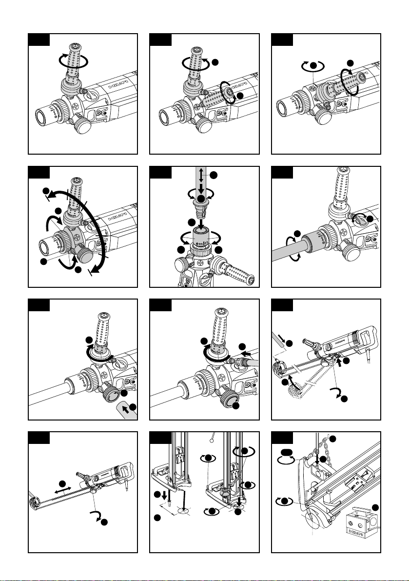
6.1 Side handle
6.1.1 Fitting the side handle
1. Screw the side handle onto the tool and tighten it
securely.
6.1.2 Fitting the side handle in a different position
1. Remove the screw plug at the position where the side
handle is to be fitted (e.g. for left-handed use). The
grip at the end of the side handle can be unscrewed
and used as a screwdriver .
2. Screw the side handle onto the tool at the desired
position and tighten it securely.
3. Insert the screw plug in the exposed threaded hole.
6.1.3 Adjusting the extraction head / water swivel (and
side handle)
1. Press the water swivel lock out of the gap between
the locking ring and the water swivel/extraction head.
2. Release the locking ring between the chuck and side
handle.
Page 10

18
Note
Use only original Hilti core bits and accessories!
1. Open the chuck by turning it counter-clockwise (as
seen from the front end of the chuck).
2. Insert the diamond core bit in the chuck.
3. Push the diamond core bit into the chuck and rotate
the core bit until it engages.
4. Close the chuck by turning it clockwise (as seen from
the front end of the chuck).
5. Check that the core bit it is securely seated by gripping it and attempting to pull it away from the chuck.
6.3 Selecting the drilling speed (gear selector posi-
tions 1-2-3)
-CAUTION-
Do not operate the gear selector while the tool is running. Wait until rotation has stopped.
Hand-held use
,
278663
4 3/4" - 6 1/2"
2
5
/8" - 4 1/4"
1
/2" - 2 1/2"
I
II
III
1
5
/8" - 2 1/2"
1
/2" - 1 1/2"IIIII
122 - 162
67 - 112
12 - 62
40 - 62
12 - 37
mm
Inch
Drill-stand use
1. Select the gear according to the table on the tool.
2. Move the gear selector to the desired setting while
rotating the core bit.
6.4 Dry drilling
6.4.1 Connecting the extraction system
1. Unscrew the cover from the water swivel / extraction
head.
2. Insert the extraction hose in the extraction connection.
3. Close the water valve in the side handle.
6.5 Hand-held wet drilling
6.5.1 Connecting the water supply
1. Close the water valve in the side handle.
2. Close the cover on the dust extraction connection.
3. Connect the water supply hose (hose connector).
6.6 Hand-held wet drilling with the water collection
system
6.6.1 Fitting the water collection system
Use of the water collection system permits water to be
drained away from the core bit thus avoiding soiling the
surrounding area. Best results are achieved in conjunction with a wet-type vacuum cleaner .
-CAUTION-
■ The core bit may become hot during
use or during sharpening.
■ It may burn your hands.
■ The cutting edges (segments) may cause
injury.
■ Wear safety gloves when changing the
core bit.
3. Move the side handle into the desired position (15°
increments).
4. Tighten the locking ring securely until the teeth and
the water swivel lock engage.
6.2 Fitting the diamond core bit
Page 11

19
Use of the water collection system in conjunction with
a wet-type vacuum cleaner is mandatory for overhead
drilling. Position the side handle and water swivel / extraction head so that the water collection system can be fitted without obstruction. The centering ring and seal
must be of a size suitable for the core bit diameter used.
1. From below the tool, position the water collection sys-
tem on the two mounting pins.
2. Swing the water collection system towards the front.
3. Secure the water collection system by turning the
knob.
4. Connect a wet-type vacuum cleaner to the front of the
water collection system. Alternatively, the water can
be allowed to flow away through a length of hose
attached to the connector (not permissible for overhead drilling).
6.6.2 Adjusting the depth gauge
1. Set the depth gauge to the desired depth.
2. Use the clamping screw to secure the depth gauge.
6.7 Using the drill stand
6.7.1 Using an anchor (HKD-D M12) to secure the
drill stand
1. Place the anchor at a distance of 200 mm (ideal dis-
tance) from the centre of the hole to be cored.
2. Screw the quick-release spindle into the anchor.
3. Place the drill stand over the quick-release spindle
and use the hole centre indicator to bring the drill
stand into alignment.
4. Fit the nut to the quick-release spindle but do not tight-
en it fully.
5. The four levelling screws should then be used to lev-
el the baseplate. The spirit level on the baseplate serves
as a levelling aid.
6. Use the locknuts to prevent further movement of the
levelling screws.
7. Tighten the nuts securely with an open-end wrench.
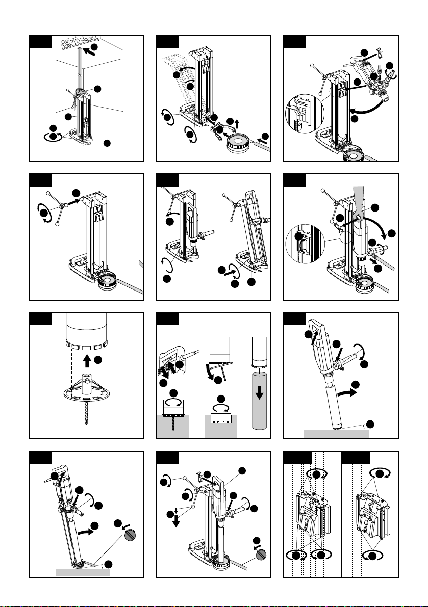
6.7.2 Securing the drill stand with the vacuum pad
A vacuum release valve is incorporated in the baseplate
grip.
Overhead drilling with the drill stand attached only by
vacuum is not permissible.
1. Unscrew the four levelling screws until they project
approx. 5 mm beneath the baseplate.
2. Connect the hose between the vacuum connector on
the baseplate and the vacuum pump.
3. Switch on the vacuum pump and extend the hole centre indicator. While pressing the vacuum release valve
and observing the hole centre indicator, bring the
baseplate into the desired position. When positioned
correctly, press the baseplate against the work surface and remove your finger from the vacuum release
valve. Before beginning drilling and during operation,
it must be ensured that the pressure gauge pointer
remains within the green area.
4. The four levelling screws should then be used to level the baseplate. The spirit level on the baseplate serves
as a levelling aid.
5. Tighten the lock nuts to prevent further movement of
the levelling screws.
6. An additional means of securing the drill stand must
be employed when drilling horizontally (e.g. a chain
attached to an anchor , ...)
6.7.3 Securing the drill stand with a quick-release
brace (e.g. between floor and ceiling)
1. Extend the hole centre indicator and then use it as an
aid to bring the drill stand into alignment with the centre point of the hole to be cored.
2. Position the end of the quick-release brace carefully
in the inner oval of the baseplate (not on the level indicator or pressure gauge).
3. Secure the baseplate by applying slight pressure with
the quick-release brace.
4. The four levelling screws should then be used to level the baseplate. The spirit level on the baseplate serves
as a levelling aid.
5. Tighten the lock nuts to prevent further movement of
the levelling screws.
6. Tighten the quick-release brace securely .
VACUUM
VACUUM
Page 12

20
6.8 Water collection system for use with the drill stand
Use of the water collection system permits water to be
drained away from the core bit thus avoiding soiling the
surrounding area. Best results are achieved in conjunction with a wet-type vacuum cleaner .
Use of the water collection system in conjunction with
a wet-type vacuum cleaner is mandatory for overhead
drilling. The drill stand must be set up at 90°to the work
surface.
The water collector sleeve and seal must be of a size
suitable for the core bit diameter used.
1. Slacken the column adjusting lever until the locating
lugs are disengaged.
2. Tilt the frame.
3. Fit the water collector holder .
4. Bring the frame back to the vertical position.
5. Close the adjusting levers until the locating lugs are
fully engaged and the frame is again secured.
6. Lift the holder and push the water collector cup under
the retainer as far as it will go.
7. Connect a wet-type vacuum cleaner to the water collector cup or connect a length of hose through which
the water can flow away.
6.9 Mounting the tool on the drill stand
The release lever on the drill stand must be in the open
position and the carriage should be at the top of its travel.
The drilling advance mechanism must be locked (chain
arrestor engaged).
1. Fit the tool interface plate onto the two mounting pins
on the drill stand.
2. Pivot the tool towards the drill stand until it engages.
3. Insert the switch lock in the grip opening. The switch
lock is used to hold the switch in the ON position during sustained operation.
4. Close the water valve in the side handle.
5. Connect the water supply .
6.10 Fitting the hand wheel
1. Fit the hand wheel onto the axle.
2. Secure the hand wheel by tightening the screw knob.
3. The hand wheel may be fitted on either side of the drill
stand.
6.11 Adjusting the drill stand drilling angle
(In increments of 7.5°; adjustable to max. 45°)
1. Slacken the column adjusting levers until the locating lugs are disengaged.
2. Bring the columns into the desired position.
3. Engage the locating lugs.
4. Move the adjusting levers until the locating lugs are
fully engaged and the frame is again secured.
5. Press in and pivot the adjusting levers to return them
to the vertical position.
6.12 Removing the tool from the drill stand
-CAUTION-
The tool must be disconnected from the electric mains
supply.
The drilling advance mechanism must be locked (chain
arrestor engaged).
1. Close the water valve in the side handle.
2. Disconnect the water supply .
3. Remove the switch lock from the grip.
4. Hold the tool with one hand on the grip and release
the lever on the drill stand.
5. Pivot the tool away from the drill stand.
7. Operation
7.1 Connect the tool to the electric mains supply
The voltage given on the rating plate must correspond
to the voltage provided by the mains supply .
1. Check that the tool is switched off or, respectively,
remove the switch lock.
2. Insert the supply cord plug in the mains socket.
3. Press the "ON" button on the PRCD ground fault interrupter (the lamp must light).
4. Press the "TEST" button on the PRCD ground fault
interrupter (the lamp must not
light).
5. Press the "ON" button on the PRCD ground fault interrupter (the lamp must light).
-CAUTION-
■ The tool and the coring operation create noise.
■ Excessive noise may damage the hearing.
■ Wear ear protection.
-CAUTION-
■ The coring operation may cause hazardous fragments to fly off.
■ Flying fragments may cause injury to
the eyes or other parts of the body.
■ Wear eye protection and a safety helmet.
7.2 Dry drilling
7.2.1 Fitting the hole-starting aid
A different hole-starting aid is required for each diamond
core bit diameter .
1. Fit the hole-starting aid into the front end of the diamond core bit.
7.2.2 Vacuum cleaner with power socket for electric
tools
The vacuum cleaner starts automatically after switching on the electric tool. Switching off the electric tool
Page 13

21
also causes the vacuum cleaner to be switched off after
a short delay.
Switching on
1. Press the on / off switch on the tool.
2. With the hole-starting aid fitted, begin drilling and
continue until the projecting segments have established a kerf in the base material.
3. Switch the tool off.
4. Remove the hole-starting aid and continue drilling.
Switching off
1. Switch the tool off.
2. Remove the core if necessary.
7.2.3 Vacuum cleaner without power socket for elec-
tric tools
Switching on
1. Switch the vacuum cleaner on.
2. Press the on / off switch on the tool.
Switching off
1. Switch the tool off.
2. Allow the vacuum cleaner to run for a short time in
order to remove remaining dust before switching off.
7.3 Hand-held wet drilling
Switching on
1. Open the water valve in the side handle until the desired
water volume flows. The water flow volume can be
observed at the indicator on the hand grip.
2. Press the on / off switch
3. When starting a hole, hold the tool at a slight angle
to the work surface. This makes hole-starting easier.
4. Once the hole has been started, bring the tool into the
90°position and continue drilling.
Switching off
1. Switch the tool off.
2. Close the water valve on the side handle.
7.4 Hand-held wet drilling using the water collection
system
The crosshair marks at the front end of the water collection system serve as an accurate positioning aid.
Switching on
1. Switch on the water extraction system (if used).
2. Open the water valve on the side handle slowly until
the desired water volume flows. Use the indicator on
the side handle to check the water flow rate.
3. Press the on / off switch.
4. Hold the tool at a slight angle to the work surface
when starting a hole. This makes hole-starting easier.
5. After starting the hole, bring the tool into the 90°position and continue drilling.
Switching off
1. Switch the tool off.
Caution: When drilling overhead, any water remain-
ing in the core bit must not be allowed to run down
over the tool.
2. Close the water valve on the side handle.
3. Switch off the vacuum cleaner (if used).
4. Remove the core if necessary.
7.5 Wet drilling using the drill stand
Switching on
1. Switch on the (wet) vacuum cleaner (if used).
2. Open the water valve at the side handle slowly until
the desired volume of water flows. The indicator at
the side handle can be used to check the water flow
rate.
3. Use the switch actuator to run the tool in sustained
operation mode.
4. Release the chain arrestor .
5. Bring the core bit into contact with the work surface
by turning the hand wheel.
6. Apply only slight pressure to the core bit when beginning drilling and then increase pressure once the core
bit has become centred.
7. Keep an eye on the overload indicator while drilling.
Pressure on the core bit must be reduced if the overload indicator lights.
Switching off
1. Close the water regulation valve at the side handle.
2. Pull the core bit out of the hole.
3. Engage the chain arrestor .
4. Switch the tool off.
5. Switch off the vacuum cleaner (if used).
6. Remove the core if necessary.
7. Switch the tool off.
Caution: When drilling overhead, any water remaining in the core bit must not be allowed to run down
over the tool.
8. Ensure stability of the drill stand by lowering the tool
and core bit to the baseplate.
8. Care and maintenance
Disconnect the supply cord plug from the socket.
8.1 Care of core bits
Remove any dirt adhering to the core bits and protect
their surfaces from corrosion by rubbing them with an
oily cloth from time to time. Always keep the connection end clean and slightly greased.
8.2 Care of the tool
Check that the supply cord plug is disconnected.
Never operate the tool if its ventilation slots are blocked.
Clean the ventilation slots carefully with a dry brush. Do
not allow foreign objects to enter the interior of the tool.
Clean the outside surfaces of the tool with a damp cloth
at regular intervals. Do not use a spray, steam cleaning
Page 14

22
equipment or running water for cleaning. This could
negatively affect the electrical safety of the tool. Always
keep the grip surfaces of the tool free from oil and grease.
Do not use cleaning agents which contain silicone.
Clean the chuck and the clamping segments with a cloth
at regular intervals and lubricate these parts with Hilti
lubricant spray. Remove any dirt and fragments from
the chuck.
Remove the filter in the water intake at the side handle
from time to time and rinse the filter sieve under running water in the direction opposite to the normal water
flow.
If the water flow indicator has become dirty, remove and
clean the parts. Do not use abrasive agents or sharp
objects to clean the sight glass. This may negatively
affect functionality of the water flow indicator .
8.3 Maintenance of the tool
Check all external parts of the tool for damage at regular intervals and check that all operating controls function faultlessly. Do not operate the tool when parts are
damaged or when operating controls do not function
faultlessly. The tool should be repaired at a Hilti service
centre.
Repairs to the electrical section of the tool may be carried out by trained electrical specialists only .
8.4 Care of the drill stand
8.4.1 Care of the chain
Check the chain guides to ensure they remain clean and
free from drilling slurry. The chain must always be protected by a film of grease.
8.5 Maintenance of the drill stand
8.5.1 Adjusting the movement
Movement should be easy but without play .
The movement can be adjusted by way of screws (2 at
the top and 2 at the bottom).
8.5.1.1 Stiffer movement
1. Release the lower screw.
2. Tighten the upper screw as far as necessary .
3. Tighten the lower screw as far as it will go.
8.5.1.2 Easier movement
1. Release the upper screw.
2. Tighten the lower screw as far as it will go.
8.5.2 Adjusting the chain tension
When the carriage is in the end position, the chain should
sag only slightly when running horizontally . Chain tension can be adjusted by way of two screws (chain symbol on the cover).
●Turning in a clockwise direction increases chain tension.
● Turning in a counter-clockwise direction decreases
chain tension.
Both chains must be tensioned equally.
Page 15

23
9. T roubleshooting
Fault Possible cause Remedy
The tool doesn't start. Fault in mains supply Plug in another electric appliance
and check whether it works.
Supply cord or plug defective The cord should be checked and
replaced if necessary by an
electrical specialist.
Switch defective The switch should be checked and
replaced if necessary by an
electrical specialist.
Motor runs but the core bit Gearing defective The tool should be repaired at a
doesn't rotate. Hilti service centre.
Rate of drilling progress decreases. Water pressure / water flow rate too Regulate the water flow rate at the
high side handle.
Core bit defective Check the core bit for damage and
replace it if necessary.
Gearing defective The tool should be repaired at a
Hilti service centre.
Core bit segments polished Resharpen the core bit on a sharp-
ening plate under water flow.
Motor cuts out. Tool stops running. Guide the tool straight.
Tool has overheated. The motor's Ease the load on the tool and allow
thermal overload protection has been it to run up to full speed by pressactivated. ing the switch several times.
Electronics defective The tool should be repaired at a
Hilti service centre.
Cooling fan defective The tool should be repaired at a
Hilti service centre.
Water does not flow. Filter or water flow indicator blocked Remove the filter or water flow
indicator and flush it through.
Water escapes at the gear housing. Shaft seal / water swivel / extraction The tool should be repaired at a
head defective Hilti service centre.
The core bit cannot be inserted in Connection end or chuck dirty or Clean the connection end and
the chuck. damaged chuck. Replace parts if necessary.
Water escapes at the chuck. Connection end or chuck dirty Clean the connection end and
chuck.
Chuck seal defective Check the seal and replace it if
necessary.
Excessive play in the drilling Excessive play at the guides Readjust the guides.
system. Chain inadequately tensioned Tension the chain.
Pivot mechanism loose Tighten the pivot mechanism
adjusting lever (6.11).
Page 16

24
10. Disposal
Most of the materials from which Hilti power tools are manufactured can be recycled. The materials must be correctly separated before they can be recycled. In many countries, Hilti has already made arrangements for taking
back your old electric tools for recycling. Please ask your Hilti customer service department or Hilti sales representative for further information.
Should you wish to return the electric tool yourself to a disposal facility for recycling, proceed as follows: Dismantle
the tool as far as possible without the need for special tools. Use absorbent paper to wipe oily parts clean and collect any oil that runs out. This paper should also be disposed of correctly. On no account should oil be allowed
to enter the waste water system or find its way into the ground.
Separate the individual parts as follows:
Part / assembly Main material Recycling
Transport box Plastic* Plastics recycling
Motor housing Plastic* / synthetic rubber Plastics recycling
Grip, side handle Plastic* Plastics recycling
Drill stand, complete Steel / aluminium / magnesium alloy / plastic* Scrap metal / plastics recycling
Motor (rotor / stator) Steel / copper Scrap metal
Gearing parts Steel Scrap metal
Screws, small parts Steel Scrap metal
Supply cord Copper / synthetic rubber Scrap metal
Drilling slurry **
**Plastic parts carry a mark indicating the material from which they are made.
** With regard to environmental aspects, allowing drilling slurry to flow directly into rivers, lakes or the sewerage
system without suitable pre-treatment is problematical. Ask the local authorities for information about applicable regulations.
We recommend the following pre-treatment:
●Collect the drilling slurry (e.g. use an industrial vacuum cleaner).
●Allow the slurry to settle and dispose of the solid material at a construction waste disposal site (the addition of
a flocculent may accelerate the settling process).
●Water from the drilling slurry (alkaline, ph value < 7) should be neutralised by adding an acidic neutralising agent
or large quantity of water before it is allowed to flow into the sewerage system.
11. Warranty
Hilti warrants that the tool supplied is free of defects in material and workmanship.This warranty is valid as long as the
tool is operated and handled correctly,cleaned and serviced
properly and in accordance with the Hilti Operating Instructions,all warranty claims are made within 12 months from
the date of the sale (invoice date),and the technical system
is maintained.This means that only original Hilti consumables,components and spare parts may be used in the tool.
This warranty provides the free-of-charge repair or replacement of defective parts only.Parts requiring repair or replacement as a result of normal wear and tear are not covered
by this warranty.
Additional claims are excluded,unless stringent national rules prohibit such exclusion.In particular ,Hilti is not
obligated for direct,indirect,incidental or consequential damages,losses or expenses in connection with,
or by reason of,the use of, or inability to use the tool
for any purpose.Implied warranties of merchantability or fitness for a particular purpose are specifically
excluded.
For repair or replacement,send tool and/or related parts
immediately upon discovery of the defect to the address of
the local Hilti marketing organization provided.
This constitutes Hilti’s entire obligation with regard to warranty and supersedes all prior or contemporaneous comments and oral or written agreements concerning warranties.
Page 17

12. EG-Konformitätserklärung
Bezeichnung: Diamantbohrgerät
Typenbezeichnung: DD130
Konstruktionsjahr: 2001
Wir erklären in alleiniger Verantwortung, dass dieses
Produkt mit den folgenden Richtlinien und Normen
übereinstimmt: EN 50144-2-1, EN 61029-1, EN
55014-1, EN 55014-2, EN 61000-3-2, EN 61000-311, 73/23/EWG, 89/336/EWG, 98/37/EG
Hilti Corporation
Ivo Celi Dr . Martin Goedickemeier
Head of Business Unit Diamond Head of Development
Business Unit Diamond Business Unit Diamond
December 2001 December 2001
12. EC declaration of conformity
Designation: Diamond drilling machine
Type: DD130
Year of design: 2001
We declare, on our sole responsibility, that this prod-
uct complies with the following standards or standardisation documents: 73/23/EEC low voltage directive (EU), 89/336/EEC EMC directive (EU), 98/37/EU
machine directive (EU), EN 50144-2-1, 61029-1, EN
55014-1, EN 55014-2, EN 61000-3-2, EN 61000-3-11.
Page 18

Hilti Corporation
FL-9494 Schaan
Tel.:+423/2342111
Fax: +423/2342 965
www.hilti.com
Hilti = registered trademark of Hilti Corp., Schaan W 2690 0102 10-Pos. 1 1 Printed in Liechtenstein © 2002
Right of technical and programme changes reserved S. E. & O.
370458
 Loading...