

Page 1

DD 120
Operating instructions en
Mode d’emploi fr
Manual de instrucciones es
Manual de instruções pt
Printed: 22.11.2013 | Doc-Nr: PUB / 5127357 / 000 / 02
Page 2
1
+≠
2
7
4
6
5
8
+[
+Ç
9
3
+|
+±
+]
+“
+{
+}
+#
+#
1
This Product is Certified
Ce produit est homologué
Producto homologado por
Este produto está registrado
C US
Printed: 22.11.2013 | Doc-Nr: PUB / 5127357 / 000 / 02
Page 3
"± "#
2
55
2
3
1
203mm/8"
4/6
"[
"Ç
"]
3
1
2
2
"{
"|
4
2
1/3
64
5
5
2
1
4
3
5
6
"“
"≠
Printed: 22.11.2013 | Doc-Nr: PUB / 5127357 / 000 / 02
Page 4
1
1
7
2
6/7
5
4
1
8
3
8
2
3
4
5
1
9
2/5
2/5
1
10
Printed: 22.11.2013 | Doc-Nr: PUB / 5127357 / 000 / 02
Page 5

ORIGINAL OPERATING INSTRUCTIONS
DD 120 diamond coring system
It is essential that the operating instructions
are read before the machine is operated for
the first time.
Always keep these operating instructions together with the machine.
Ensure that the operating instructions are
with the machine when it is given to other
persons.
Contents Page
1 General information 1
2Description 3
3 Accessories 5
4 Technical data 6
5 Safety instructions 6
6Beforeuse 9
7 Operation 12
8 Care and maintenance 15
9 Troubleshooting 16
10 Disposal 17
11 Manufacturer’s warranty 18
1 These numbers refer to the corresponding illustrations. The illustrations can be found on the fold-out cover
pages. Keep these pages open while studying the operating instructions.
In these operating instructions, the designation “the machine” always refers to the DD 120 diamond core drilling
system.
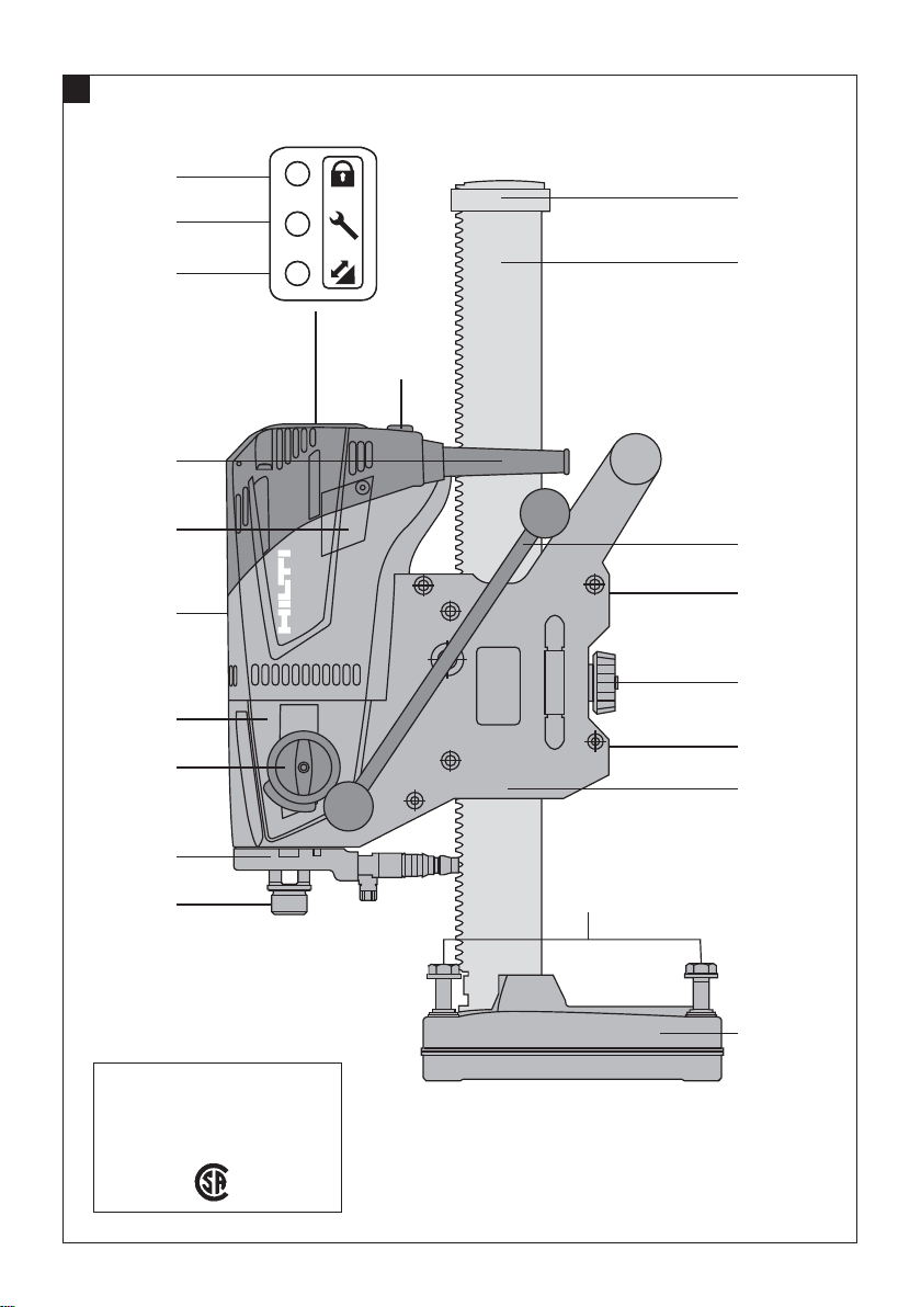
Operating controls, parts and indicators (drive unit
and drill stand) 1
Drilling performance indicator
;
On/off switch
=
Gear selector
%
Gearing section
&
Motor
(
Carbon brush cover
)
Water swivel
+
Supply cord with GFCI
§
Theft protection indicator (option)
/
Carriage
:
Carriage brake
·
Carriage play adjustment screws
$
Rail
£
Chuck
|
Anchor base plate
¡
Handwheel
Q
End stop
W
Leveling screws
E
Alternative: Combination base plate (anchor or vacuum) 2
Pressure gauge
R
Vacuum release valve
T
Vacuum seal
Z
Vacuum hose connector
U
Accessories 3
Fastening accessories
Clamping spindle
I
Clamping spindle nut
O
Anchor
P
Water collection system 4
en
DD 120 diamond core drilling system
Service indicator
@
1 General information
1.1 Safety notices and their meaning
DANGER
Draws attention to imminent danger that will lead to
seriousbodilyinjuryorfatality.
WARNING
Draws attention to a potentially dangerous situation that
could lead to serious personal injury or fatality.
Water collector bracket
Ü
Water collector
[
CAUTION
Draws attention to a potentially dangerous situation that
could lead to slight personal injury or damage to the
equipment or other property.
NOTE
Draws attention to an instruction or other useful information.
1
Page 6
1.2 Explanation of the pictograms and other
information
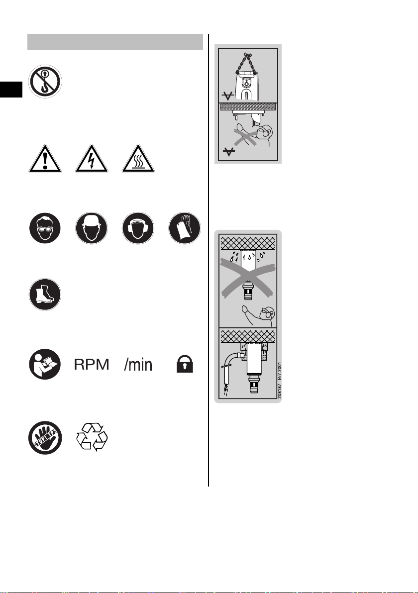
Prohibition signs
On the combination base plate
en
Transport by
crane is not
permissible.
Warning signs
Obligation signs
Wear eye
protection.
Wear safety
Symbols
General
warning
shoes.
Warning:
electricity
Wear a hard
hat.
Warning: hot
surface
Wear ear
protection.
Wear
protective
gloves.
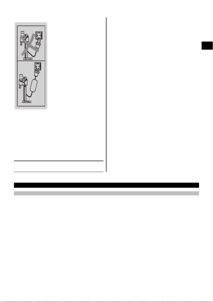
VACUUM
VACUUM
Upper: An additional means of securing the drill stand
must be employed when the machine is used for horizontal drilling with the vacuum securing method.
Lower: Use of the vacuum securing method for overhead
drilling with the drill stand is not permissible.
On the machine
Read the
operating
instructions
before use.
Equipped
with theft
protection
system
2
Revolutions
per minute
Return waste
material for
recycling.
Revolutions
per minute
Lock symbol
Use of the water collection system in conjunction with
a wet-type industrial vacuum cleaner is a mandatory
requirement for working on ceilings.
Page 7
On the machine
PRCD
GFCI
208188 B/2.2004
Operate the equipment only with a properly functioning
GFCI.
Location of identification data on the machine
The type designation and serial number can be found on
thetypeidentificationplateonthemachine.Makeanote
of this data in your operating instructions and always refer
to it when making an enquiry to your Hilti representative
or service department.
Type:
en
Serial no.:
2 Description
2.1 Use of the product as directed
The DD 120 is an electrically-powered, rig-type diamond core drilling machine for drilling through-holes and blind
holes in (reinforced) mineral materials using diamond core bits and the wet drilling technique (hand-held use is not
permissible).
The machine must be adequately secured to the working surface with an anchor or vacuum base plate before use.
To avoid injury, use only genuine Hilti core bits and DD 120 accessories.
Observe the safety rules and operating instructions for the accessories used.
Observe the information printed in the operating instructions concerning operation, care and maintenance.
Nationally applicable industrial safety regulations must be observed.
The machine, accessories and cutting tools may present hazards when handled incorrectly by untrained personnel or
when used not as directed.
Use of the water collection system in conjunction with a wet-type industrial vacuum cleaner is a mandatory requirement
for working overhead.
An additional means of securing the drill stand must be employed when the machine is secured with the vacuum base
plate (accessory) for horizontal drilling.
Do not strike the base plate with a hammer or other heavy object when making adjustments to it.
Tampering with or modification of the machine, drill stand and accessoriesisnotpermissible.
3
Page 8

WARNING
The machine may be operated only when connected to an adequately-rated electric supply equipped with an
earth (ground) conductor.
WARNING
Drilling into materials hazardous to the health (e.g. asbestos) is not permissible.
en
DANGER
Use only the genuine Hilti accessories or ancillary equipment listed in the operating instructions. Use of
accessories or ancillary equipment not listed in the operating instructions may present a risk of personal injury.
2.2 Use of the system with various items of equipment
Equipment
With water collection system and wet-type industrial vacuum cleaner
Without water collection system and wet-type
industrial vacuum cleaner
With water collection system 16…132 mm (⁵/₈" ‑ 5¹/₄") Not upwards
2.3 Gears and corresponding core bit diameters
Gear
1 57…132
2 16…52
NOTE
Second gear may be used to achieve faster progress when drilling holes up to 82 mm (3¹/₂") in diameter in lightly
reinforced concrete.
2.4 Status indicator 1
LED indicators State Description / information
Theft protection indicator (10) Blinking yellow light The machine's theft protection system
Service indicator (1) Red light and the machine
Drilling performance display (2) Orange light Contact pressure too low
Core bit diameters
(mm)
Core bit diameters
16…132 mm (⁵/₈" ‑ 5¹/₄")
16…132 mm (⁵/₈" ‑ 5¹/₄")
Core bit diameters
(inches)
2¹⁄₄…5¹⁄₄
⁵⁄₈…2
is active and must be unlocked with the
TPS key.
starts
Red light and the machine
doesn’t start
Blinking red light
Green light Optimum contact pressure
Red light Contact pressure too high
Blinking red light The machine has temporarily
The carbon brushes are badly worn.
After the lamp lights for the first time,
the machine may continue to be used
for several hours before the automatic
cut-out is activated. Have the carbon
brushes changed in good time so that
the machine is always ready for use.
The carbon brushes must be changed.
Motor speed error, see section “Troubleshooting”.
overheated, see section
“Troubleshooting”.
Drilling direction
All directions
Not upwards
No-load speed
(r.p.m.)
650
1,380
4
Page 9

2.5 TPS theft protection system (optional)
The machine may be optionally equipped with the TPS theft protection system. If equipped with this feature, the
machine can be unlocked and made ready for operation only through use of the corresponding TPS key.
2.6 The items supplied as standard include:
1 Machine including hand wheel
1 Operating instructions
1 Hilti toolbox or cardboard box
2.7 Using extension cords
Use only extension cords of a type approved for the application and with conductors of adequate gauge.
Recommended minimum conductor cross section and max. cable lengths
Conductor cross section 14 AWG 12 AWG
Mains voltage 110-120 V 50 ft 150 ft
Do not use extension cords with 16 AWG conductor cross section. Use only extension cords equipped with an earth
conductor.
2.8 Using a generator or transformer
This machine may be powered by a generator or transformer when the following conditions are fulfilled: The unit must
provideapoweroutputinwattsofatleasttwicethevalueprintedonthetype identification plate on the machine. The
operating voltage must remain within +5% and -15% of the rated voltage at all times, frequency must be in the 50 – 60
Hz range and never above 65 Hz, and the unit must be equipped with automatic voltage regulation and starting boost.
NOTE
Switching other machines or appliances on and off can cause undervoltage and/or overvoltage peaks which could
damage the machine. Never operate other machines from the generator/transformer at the same time.
3 Accessories
en
Designation Item number, description
TPS theft protection system with company card, company remote and TPS‑K key
Water collector bracket 331622
Flow indicator (BI+) 305939
Handwheel (lever) 332023
Handwheel (star handle) 332033
Clamping nut 333477
Clamping spindle 333629
Set of seals for combination base plate 333846
Leveling screw 351954
Core bit extension (BI+) 220929
Drill stand (anchor base plate, 600 mm rail, only as
replacement part)
Drill stand (anchor base plate, 720 mm rail) 352164
Drill stand (anchor base plate, 830 mm rail, only as
replacement part)
Drill stand (anchor base plate, 720 mm rail with tilt
mechanism)
Option
334206
277337
335883
5
Page 10

Designation Item number, description
Drill stand (combination base plate, 830 mm rail with
tilt mechanism)
Vacuum base plate 232991
335896
en
4 Technical data
Right of technical changes reserved.
Rated voltage [V] 120
Rated current [A] 14.1
Mains frequency [Hz] 60
Rated speed under no load, 1st gear [/min] 650
Rated speed under no load, 2nd gear [/min] 1,380
Other information about the machine
Max. permissible water supply pressure 6 bar (87.02 psi)
Dimensions of drill stand with short rail (L x W x H) 330 mm (12.99") x 147 mm (5.79") x 600 mm (23.62")
Dimensions of drill stand with medium rail (L x W x H) 330 mm (12.99") x 147 mm (5.79") x 720 mm (28.35")
Dimensions of drill stand with long rail (L x W x H) 330 mm (12.99") x 147 mm (5.79") x 830 mm (32.68")
Weight (600 mm rail) 9.8 kg (21.61 lb)
Protection class Protection class I (earthed)
5 Safety instructions
5.1 General safety rules
a) Warning! Read and understand all instructions.
Failure to follow all instructions listed below may
result in electric shock, fire and/or serious personal
injury. SAVE THESE INSTRUCTIONS.
5.1.1 Work area
a) Keep your work area clean and well lit. Cluttered
benches and dark areas invite accidents.
b) Do not operate power tools in explosive atmo-
spheres, such as in the presence of flammable
liquids, gases or dust. Power tools create sparks
which may ignite the dust or fumes.
c) Keep bystanders, children and visitors away while
operating a power tool. Distractions can cause you
to lose control.
5.1.2 Electrical safety
a) Grounded tools must be plugged into an outlet
properly installed and grounded in accordance
with all codes and ordinances. Never remove the
grounding prong or modify the plug in any way. Do
not use any adapter plugs. Check with a qualified
electrician if you are in doubt as to whether the
outlet is properly grounded. If the tools should
electrically malfunction or break down, grounding
provides a low resistance path to carry electricity
away from the user.
b) Avoid body contact with grounded surfaces such
as pipes, radiators, ranges and refrigerators.
There is an increased risk of electric shock if your
body is grounded.
c) Don’t expose power tools to rain or wet condi-
tions. Water entering a power tool will increase the
risk of electric shock.
d) Do not abuse the cord. Never use the cord to carry
the tools or pull the plug from an outlet. Keep cord
away from heat, oil, sharp edges or moving parts.
Replace damaged cords immediately. Damaged
cords increase the risk of electric shock.
e) When operating a power tool outside, use an
outdoor extension cord marked “W-A” or “W”.
These cords are rated for outdoor use and reduce
the risk of electric shock.
5.1.3 Personal safety
a) Stay alert, watch what you are doing and use
common sense when operating a power tool. Do
not use tool while tired or under the influence of
drugs, alcohol or medication. A moment of inatten-
tion while operating power tools may result in serious
personal injury.
6
Page 11

b) Dress properly. Do not wear loose clothing or
jewelry. Contain long hair. Keep your hair, clothing
and gloves away from moving parts. Loose clothes,
jewelry or long hair can be caught in moving parts.
c) Avoid accidental starting. Be sure switch is off
before plugging in. Carrying tools with your finger
on the switch or plugging in tools that have the switch
on invites accidents.
d) Remove adjusting keys or switches before turning
the tool on. Awrenchorakeythatisleftattached
to a rotating part of the tool may result in personal
injury.
e) Do not overreach. Keep proper footing and bal-
ance at all times. Proper footing and balance enables better control of the tool in unexpected situations.
f) Use safety equipment. Always wear eye protec-
tion.Dust mask, non-skid safety shoes, hard hat or
hearing protection must be used for appropriate conditions.
5.1.4 Tool use and care
a) Use clamps or other practical way to secure and
support the workpiece to a stable platform. Hold-
ing the work by hand or against your body is unstable
and may lead to loss of control.
b) Do not force tool. Use the correct tool for your
application. Thecorrecttoolwilldothejobbetter
and safer at the rate for which it is designed.
c) Do not use tool if switch does not turn it on or off.
Any tool that cannot be controlled with the switch is
dangerous and must be repaired.
d) Disconnectthe plug from the power source before
making any adjustments, changing accessories,
or storing the tool. Such preventive safety measures
reduce the risk of starting the tool accidentally.
e) Store idle tools out of reach of children and
other untrained persons. Tools are dangerous in
the hands of untrained users.
f) Maintain tools with care. Keep cutting tools sharp
and clean. Properly maintained tools with sharp cutting edges are less likely to bind and are easier to
control.
g) Check for misalignment or binding of moving
parts, breakage of parts and any other condition
that may affect the tool’s operation. If damaged,
have the tool serviced before using. Many acci-
dents are caused by poorly maintained tools.
h) Use only accessories that are recommended by
the manufacturer for your model. Accessories that
may be suitable for one tool may become hazardous
when used on another tool.
5.1.5 Service
a) Tool service must be performed only by qualified
repair personnel. Service or maintenance performed
by unqualified personnel could result in a risk of injury.
b) When servicing a tool, use only identical replace-
ment parts. Follow instructions in the Maintenance section of this manual. Use of unauthorized
parts or failure to follow Maintenance Instructions
may create a risk of electric shock or injury.
5.2 Additional safety instructions
Read all instructions before using this electric tool or
machine and keep the safety instructions in a safe
place.
5.2.1 Proper organization of the work area
a) Approval must be obtained from the site engineer
or architect prior to beginningdrilling work. Drilling
work on buildings and other structures may influence
the statics of the structure, especially when steel
reinforcing bars or load-bearing components are cut
through.
b) Ensure that the workplace is well ventilated. Ex-
posure to dust at a poorly ventilated workplace may
result in damage to the health.
c) Keep the workplace tidy. Objects which could
cause injury should be removed from the working area. Untidiness at the workplace can lead to
accidents.
d) When drilling through walls, cover the area behind
the wall, as material or the core may fall out on
the other side of the wall. When drilling through
ceilings, secure (cover) the area below as drilled
material or the core may drop out and fall down.
e) Wear respiratory protection if the work causes
dust.
f) It is recommended that rubber gloves and non-
skid shoes are worn when working outdoors.
g) Do not allow other persons to touch the machine
or the extension cord.
h) Always lead the supply cord, extension cord and
water hose away from the tool or machine to the
rear to prevent a tripping hazard while working.
i) Keep the supply cord, extension cord, suction
hose and vacuum hose away from rotating parts.
j) CAUTION: Before beginning drilling, check that
there are no live electric cables located in the
base material.
k) Concealed electric cables or gas and water pipes
present a serious hazard if damaged while you
are working. Accordingly, check the area in which
you are working beforehand (e.g. using a metal
detector). External metal parts of the machine may
become live, for example, when an electric cable is
damaged accidentally.
l) Do not work from a ladder.
m) WARNING: Some dust created by grinding, sand-
ing, cutting and drilling contains chemicals known
to cause cancer, birth defects, infertility or other
reproductive harm; or serious and permanent respiratory or other injury. Some examples of these
chemicals are: lead from lead-based paints, crystalline silica from bricks, concrete and other masonry
products and natural stone, arsenic and chromium
from chemically-treated lumber. Your risk from these
exposures varies, depending on how often you do
en
7
Page 12

this type of work. To reduce exposure to these
chemicals, the operator and bystanders should
work in a well-ventilated area, work with approved safety equipment, such as respiratory protection appropriate for the type of dust generated,
and designed to filter out microscopic particles
en
and direct dust away from the face and body.
Avoid prolonged contact with dust. Wear protective clothing and wash exposed areas with soap
and water. Allowing dust to get into your mouth,
nose, eyes, or to remain on your skin may promote
absorption of harmful chemicals.
5.2.2 General safety rules
out sticking and that no parts are damaged. All
parts must be fitted correctly and fulfill all conditions necessary for correct operation of the machine. Damaged guards, safety devices and other
parts must be repaired or replaced properly at an
authorized service center unless otherwise indicated in the operating instructions.
m) Avoid skin contact with drilling slurry.
n) Wear a protective mask during work that gen-
erates dust, e.g. dry drilling. Connect a dust removal system. Drilling in materials hazardous to
the health (e.g. asbestos) is not permissible.
5.2.3 Mechanical
a) Use the right tool or machine for the job. Do not
use the tool or machine for purposes for which
it was not intended. Use it only as directed and
when in faultless condition.
b) Use the power tool, accessories and tool bits etc.
in accordance with these instructions taking into
account the working conditions and the work to
be performed. Use of the power tool for opera-
tions different from those intended could result in a
hazardous situation.
c) Use only the genuine Hilti accessories or ancillary
equipment listed in the operating instructions. Use
of accessories or ancillary equipment not listed in the
operating instructions may present a risk of personal
injury.
d) Keep the grips dry, clean and free from oil and
grease.
e) Never leave the machine unattended.
f) Store machines in a secure place when not in use.
When not in use, machines must be stored in a
dry, high place or locked away out of reach of
children.
g) Always disconnect the supply cord from the elec-
tric supply when the machine is not in use (e.g.
during breaks between working), before making
adjustments, before carrying out care and maintenance and before changing core bits. This safety
precaution prevents the machine starting unintentionally.
h) Keep children away. Keep other persons away
from the working area.
i) Children must be instructed not to play with the
machine.
j) The machine is not intended for use by children,
by debilitated persons or those who have received
no instruction or training.
k) Never operate the machine without the GFCI sup-
plied with it. Test the GFCI each time before use.
l) Check the machine and its accessories for any
damage. Guards, safety devices and any slightly
damaged parts must be checked carefully to ensure that they function faultlessly and as intended.
Check that moving parts function correctly with-
a) Follow the instructions concerning care and main-
tenance.
b) Follow the instructions concerning lubrication
andchangingcorebits.
c) Check that the core bits used are compatible with
the chuck system and that they are secured in the
chuck correctly.
d) Make sure that the machine is correctly and se-
curely mounted on the drill stand.
e) Do not touch rotating parts.
f) Check that all the clamping screws are correctly
tightened.
g) Make sure that the cover with built-in end stop
is always fitted to the drill stand. The safetyrelevant end-stop function becomes inoperative
if this component is not fitted.
5.2.4 Electrical
a) Check the condition of the machine and its ac-
cessories. Do not operate the machine and its
accessories if damage is found, if the machine is
incomplete or if its controls cannot be operated
faultlessly.
b) Do not touch the supply cord or extension cord
if it is damaged while working. Disconnect the
supply cord plug from the power outlet.
c) Damaged or faulty switches must be replaced at
a Hilti service center. Do not use the machine if it
cannot be switched on and off correctly.
d) Have the machine repaired only by a trained elec-
trical specialist (Hilti service center) using genuine
Hilti spare parts. Failure to observe this point may
result in risk of accident to the user.
e) Check the machine’s supply cord at regular inter-
vals and have it replaced by a qualified specialist
if found to be damaged. Check extension cords
8
Page 13

at regular intervals and replace them if found to
be damaged.
f) When working outdoors, use only extension cords
that are approved and correspondingly marked
for this application.
g) In case of an interruption in the electric supply:
Switch the machine off and unplug the supply
cord.
h) Avoid using extension cords with multiple power
outlets and the simultaneous use of several electric tools or machines connected to one extension
cord.
i) Never operate the machine when it is dirty or
wet. Dust (especially dust from conductive materials) or dampness adhering to the surface of the
machine may, under unfavorable conditions, lead
to electric shock. Dirty or dusty machines should
thus be checked at a Hilti service center at regular
intervals, especially if used frequently for working
on conductive materials.
5.2.5 Thermal
5.2.6 Requirements to be met by users
a) The machine is intended for professional use.
b) The machine may be operated, serviced and re-
paired only by authorized, trained personnel. This
personnel must be informed of any special hazards that may be encountered.
c) Stay alert, watch what you are doing and use
common sense when operating a power tool. Do
not use a power tool while you are tired or under
the influence of drugs, alcohol or medication. A
moment of inattention while operating power tools
may result in serious personal injury.
d) Improve the blood circulation in your fingers by
relaxing your hands and exercising your fingers
during breaks between working.
5.2.7 Personal protective equipment
en
Wear protective gloves when changing core bits. The
core bit may become hot during use.
6Beforeuse
CAUTION
The mains voltage must comply with the specification
given on the type identification plate. Ensure that the
power tool is disconnected from the electric supply.
DANGER
When drilling through walls, cover the area behind
the wall, as material or the core may fall out on the
other side of the wall. When drilling through ceilings,
secure (cover) the area below as drilled material or
the core may drop out and fall down.
DANGER
Check that the drill stand is securely fastened to the
base material.
CAUTION
Do not break the connection to earth by using an
adaptor plug.
The user and any other persons in the vicinity must
wear ANSI Z87.1-approved eye protection, a hard
hat, ear protection, protective gloves and breathing
protection while the machine is in use.
6.1 Preparing for use
CAUTION
The machine and the diamond core bit are heavy. There
is a risk of pinching parts of the body. Wear a hard hat,
protective gloves and safety boots.
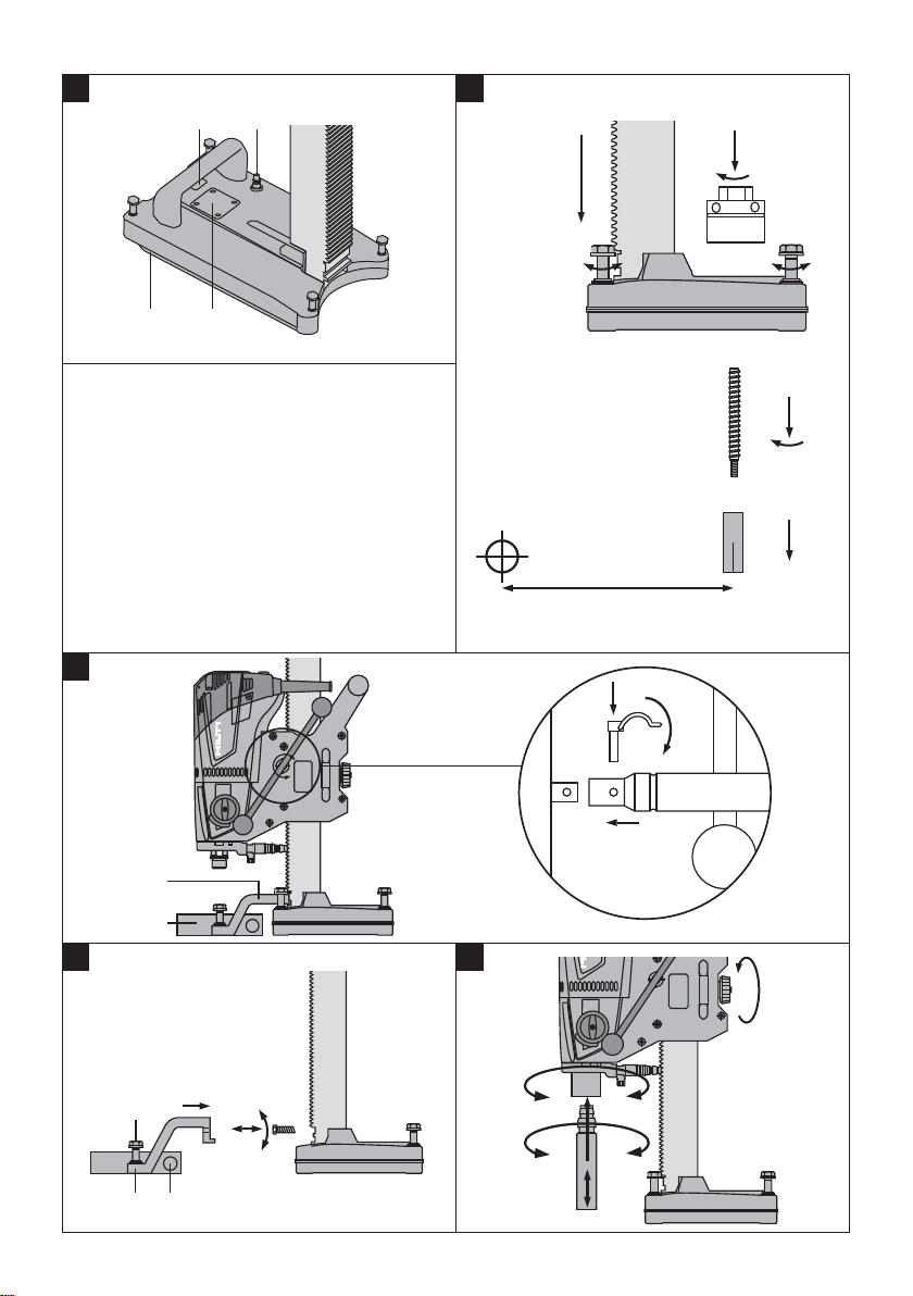
6.1.1 Fitting the handwheel 4
NOTE
The handwheel may be fitted on the left-hand or righthand side of the carriage.
1. Fit the handwheel onto the shaft on the left-hand or
right-hand side of the carriage.
2. Secure the handwheel with the retaining pin.
6.1.2 Fastening the drilling system with an
anchor 3
WARNING
Use an anchor suitable for the material on which you
are working and observe the anchor manufacturer’s
instructions.
9
Page 14

NOTE
Hilti M12 metal expansion anchors are usually suitable for
fastening diamond core drilling equipment to uncracked
concrete. Under certain conditions it may be necessary
to use an alternative fastening method. Please contact
Hilti Technical Service if you have any questions about
secure fastening.
en
1. Set the anchor that is suitable for the material on
which you are working at the (ideal) distance of
203 mm (8") from the center of the hole to be drilled.
2. Screw the clamping spindle (accessory) into the
anchor.
3. Place the drill stand base plate over the spindle and
align it.
4. Screw the clamping nut (accessory) onto the spindle
but do not tighten it.
5. Level the base plate by turning the four leveling
screws. Take care to ensure that the leveling screws
make firm contact with the underlying surface.
6. Use a 19 mm AF open-end wrench to tighten the
clamping nut on the clamping spindle.
7. Make sure that the drilling system is securedreliably.
6.1.3 Fastening the drill stand with the vacuum
base plate
DANGER
A coated, laminated, rough or uneven surface may significantly reduce the effectiveness of the vacuum system.
Check whether the surface is suitable for use of the
vacuum method to fasten the drill stand.
DANGER
Overhead drilling with the machine secured only by
the vacuum base plate is not permissible.
CAUTION
Make yourself familiar with information contained in
the operating instructions for the vacuum pump and
follow these instructions before using it.
WARNING
Before beginning drilling and during operation it must
be ensured that the pressure gauge indicator remains
within the green area.
VACUUM
NOTE
When using the vacuum base plate: Screw the anchor
base plate onto the vacuum base plate.
1. Turn (retract) the 4 leveling screws until they project
approx. 5 mm beneath the combination base plate
or, respectively, the vacuum base plate.
2. Connect the vacuum connector of the combination
base plate to the vacuum pump.
3. Locate the center point of the hole to be drilled.
4. Draw a line approximately 800 mm in length from
the center of the hole to be drilled towards where
the drill stand is to be positioned.
5. Makeamarkonthelineatadistanceof203mm
(8") from the center of the hole to be drilled.
6. Switch on the vacuum pump and press the vacuum
release valve.
7. Bring the mark on the combination base plate or
vacuum base plate into alignment with the line.
8. Once the drill stand has been positioned correctly,
release the vacuum release valve and press the base
plate against the base material.
9. Level and steady the combination base plate or
vacuum base plate by turning the 4 leveling screws.
10. An additional means of securing the drilling system
must be provided when drilling horizontally. (e.g. a
chain attached to an anchor, etc.)
11. Make sure that the drilling system is secured reliably.
6.1.4 Adjusting the drilling angle (optional for rails
with tilt mechanism)
CAUTION
There is a risk of crushing the fingers in the pivot mechanism. Wear protective gloves.
1. Release the screw on the rail tilt mechanism.
2. Adjust the rail to the desired angle.
3. Retighten the screw securely.
6.1.5 Fitting the water connection
CAUTION
Regularly check the hoses for damage and make sure
that the maximum permissible water supply pressure
of 6 bar is not exceeded.
CAUTION
Make sure that the hose doesn’t come into contact
with rotating parts.
CAUTION
Make sure that the hose is not pinched and damaged
as the carriage advances.
VACUUM
10
Page 15

CAUTION
Do not change gear while the machine is running.
Wait for the spindle to come to a halt.
NOTE
To avoid damage to the components, use only fresh
water containing no dirt particles.
NOTE
A flow meter (accessory) may be fitted between the
machine’s water supply connector and the water supply
hose.
1. Connect the water regulator to the machine.
2. Connect the water supply (hose coupling).
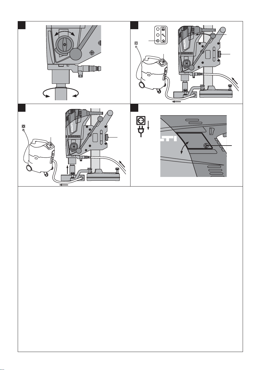
6.1.6 Fitting the water collection system
(accessory) 5
WARNING
Use of the water collection system in conjunction with
a wet-type industrial vacuum cleaner is a mandatory
requirement for work on ceilings. The machine must
be positioned at an angle of 90° to the ceiling. The
seal used must be of the correct size for the diamond
core bit diameter.
NOTE
Use of the water collection system allows water to be
led away in controlled fashion, thus avoiding a mess
or damage to the surrounding area. Best results are
achieved with a wet-type industrial vacuum cleaner.
1. Release the hexagon-head screw at the front of the
rail.
2. Push the water collector holder into position.
3. Fit the hexagon-head screw and tighten it.
4. Fit the water collector between the two moveable
arms of the water collector holder.
5. Press the water collector against the base material
by turning the two screws on the water collector
holder.
6. Connect a wet-type industrial vacuum cleaner to the
water collector or fit a length of hose through which
the water can drain away.
6.1.7 Fitting the diamond core bit 6
DANGER
Do not use damaged core bits. Check the core bits for
chipping, cracks, or heavy wear each time before use.
Do not use damaged tools. Fragments of the workpiece
orabrokencorebitmaybeejectedandcauseinjury
beyondtheimmediateareaofoperation.
NOTE
Diamond core bits must be replaced when the cutting
performance and/or rate of drilling progress drops sig-
nificantly. This generally is the case when the segments
reach a height of less than 2 mm.
DANGER
To avoid injury, use only genuine Hilti core bits and
DD 120 accessories. If using a machine with a BI+
chuck, only genuine Hilti core bits may be used with
it.
CAUTION
The core bit may become hot during use or during sharpening. There is a risk of burning your hands. Wear pro-
tective gloves when changing the core bit.
DANGER
Fitting and positioning the core bit incorrectly can lead
to hazardous situations as this may cause parts to break
and fly off. Check that the core bit is seated correctly.
CAUTION
Disconnect the supply cord plug from the power outlet.
NOTE
C-Rod, A-Rod, M27, and BR chucks are operated with a
27 mm AF open-end wrench.
1. Use the carriage brake to lock the carriage in position on the rail and check that the system components are securely mounted.
2. Open the chuck (BI+) by turning it in the direction of
the open brackets symbol.
3. Push the diamond core bit into the chuck (BI+) from
below, turning the core bit until the teeth in the
chuck engage with the core bit.
4. Close the chuck (BI+) by turning it in the direction of
the closed brackets symbol.
5. Check that the diamond core bit is securely mounted
in the chuck by pulling on the core bit and attempting
to move it from side to side.
6.1.8 Selecting the speed 7
CAUTION
Do not change gear while the machine is running.
Wait for the spindle to come to a halt.
1. Set the selector switch according to the core bit
diameter used. Turn the selector switch to the recommended setting (see section “Description”) while
rotating the core bit by hand.
6.1.9 Removing the diamond core bit
CAUTION
The core bit may become hot during use or during sharpening. There is a risk of burning your hands. Wear pro-
tective gloves when changing the core bit.
en
11
Page 16

CAUTION
Disconnect the supply cord plug from the power outlet.
NOTE
If using a C-Rod, A-Rod, M27 or BR chuck, lock the drive
shaft with an M27 open-end wrench and use a suitable
en
open-end wrench to release the core bit.
7Operation
WARNING
Make sure that the supply cord does not come into
contact with rotating parts.
WARNING
Make sure that the supply cord is not pinched and
damaged as the carriage advances.
CAUTION
The machine and the drilling operation generate noise.
Wear ear protectors. Excessive noise may damage the
hearing.
CAUTION
Drilling may cause hazardous flying fragments. Flying
fragments present a risk of injury to the eyes and body.
Wear eye protection and a hard hat.
1. Turn the carriage brake lever to lock the carriage on
the rail. Check that it is mounted securely.
2. Open the chuck (BI+) by turning it in the direction of
the open brackets symbol.
3. Pull the sleeve on the chuck in the direction of the
arrow towards the machine.This releases the core
bit.
4. Remove the core bit.
7.1.2 Activation of the theft protection system for
the machine
NOTE
Further detailed information on activation and use of the
theft protection system can be found in the operating
instructions for the theft protection system.
7.2 Switching on and checking the ground fault
circuit interrupter (GFCI)
7.1 TPS theft protection system (optional)
NOTE
The machine may be equipped with the optional theft
protection system. If the machine is equipped with this
feature, it can be unlocked and made ready for operation
only with the corresponding TPS key.
7.1.1 Unlocking the machine
1. Connect the supply cord to the electric supply and
press the “I” or “Reset” button on the ground fault
circuit interrupter. The yellow theft protection indicator LED blinks. The machine is now ready to receive
the signal from the TPS key.
2. Hold the TPS key or the TPS watch strap buckle
against the lock symbol. The machine is unlocked
as soon as the yellow theft protection indicator LED
no longer lights.
NOTE If, for example, the electric supply is briefly
interrupted due to a power failure or disconnected
when moving to a different workplace, the machine
remains ready for operation for approx. 20 minutes.
Intheeventofalongerinterruption,theTPSkey
must be used again to unlock the machine.
12
PRCD
GFCI
208188 B/2.2004
(Note: An isolating transformer is used with the GB version.)
1. Plug the machine’s supply cord into an
earthed/grounded power outlet.
2. Press the “I” or “Reset” button on the ground fault
circuit interrupter (GFCI).
The drilling performance indicator lights orange.
3. Press the “0” or “Test” button on the ground fault
circuit interrupter (GFCI).
The indicator must go out.
Page 17

4. WARNING If the indicator continues to light, fur-
ther operation of the machine is not permissible.Have the machine repaired by trained personnel
using genuine Hilti spare parts.
Press the “I” or “Reset” button on the ground fault
circuit interrupter (GFCI).
The indicator must light.
7.3 Drilling without use of the water collection
system and industrial vacuum cleaner
WARNING
Water must not be allowed to run over the motor and
cover.
WARNING
Water drainage is uncontrolled. Overhead drilling is not
permissible.
1. Slowly open the water flow regulator until the desired
volume of water is flowing.
2. Press the on/off switch on the machine (position “I”).
The drilling performance indicator lights orange.
3. Release the carriage brake.
4. Turn the handwheel until the diamond core bit is in
contact with the base material.
5. Apply only light pressure until the diamond core bit
has centered itself and then increase the pressure.
6. Regulate the contact pressure while observing the
drilling performance indicator.
NOTE The drilling performance indicator lights orange after switching on. Optimum drilling performance is achieved when the drilling performance
indicator shows a green light. If the drilling performance indicator shows a red light, reduce the
pressure applied to the core bit.
7.4 Drilling with use of the water collection system
(accessory)
en
WARNING
Water must not be allowed to run over the motor and
cover.
CAUTION
The water is drained through a hose. Overhead drilling
is not permissible.
1. Slowly open the water flow regulator until the desired
volume of water is flowing.
2. Press the on/off switch on the machine (position “I”).
The drilling performance indicator lights orange.
3. Release the carriage brake.
4. Turn the handwheel until the diamond core bit is in
contact with the base material.
5. Apply only light pressure until the diamond core bit
has centered itself and then increase the pressure.
6. Regulate the contact pressure while observing the
drilling performance indicator.
NOTE The drilling performance indicator lights orange after switching on. Optimum drilling performance is achieved when the drilling performance
indicator shows a green light. If the drilling performance indicator shows a red light, reduce the
pressure applied to the core bit.
13
Page 18

7.5 Drilling with use of the water collection system
and wet-type industrial vacuum cleaner
(accessories) 8
en
WARNING
Water must not be allowed to run over the motor and
cover.
WARNING
The diamond core bit fills with water during overhead
drilling. Drilling upwards at an angle is not permissible
(the water collector cannot function correctly).
NOTE
The vacuum cleaner must be switched on manually before drilling is started and switched off manually once
drilling is completed.
1. Switch the vacuum cleaner on. Do not use the
vacuum cleaner in automatic mode.
2. Connect the water supply.
3. Open the water flow regulator.
4. Press the on/off switch on the machine (position “I”).
The drilling performance indicator lights orange.
5. Release the carriage brake.
6. Turn the handwheel until the diamond core bit is in
contact with the base material.
7. Apply only light pressure until the diamond core bit
has centered itself and then increase the pressure.
8. Regulate the contact pressure while observing the
drilling performance indicator.
NOTE The drilling performance indicator lights orange after switching on. Optimum drilling performance is achieved when the drilling performance
indicator shows a green light. If the drilling performance indicator shows a red light, reduce the
pressure applied to the core bit.
7.6 Switching off 9
WARNING
Exercise caution when drilling overhead : The diamond
core bit fills with water during overhead drilling. As a
first step, carefully allow the water to drain away
after completing overhead drilling. This is done by
disconnecting the water supply from the water flow
regulator and draining the water by opening the water
flow regulator. Do not allow the water to run over the
motor and cover.
1. Close the water flow regulator.
2. Remove the diamond core bit from the hole.
3. Engage the carriage brake.
4. Switch the drilling machine off.
5. Switch off the industrial vacuum cleaner.
7.7 Procedure in the event of the core bit sticking
The safety clutch releases in the event of the core bit
binding and sticking. Following this, the motor is switched
off by the electronic control system. If the user takes no
action, the electronic control system switches the motor
on twice automatically. If the core bit still can’t be freed,
the electronic control system switches the motor off for
90 seconds. The core bit can be released by taking the
following action:
7.7.1 Using an open-end wrench to release the
core bit
1. Disconnect the supply cord plug from the power
outlet.
2. Gripthecorebitwithasuitableopen-endwrench
close to the connection end and release the core bit
by rotating it.
3. Plug the machine’s supply cord into the power outlet.
4. Resume the drilling operation.
7.7.2 Using the spider wheel to release the core bit
1. Disconnect the supply cord plug from the power
outlet.
2. Usethespiderwheeltorotatethecorebitand
release it from the base material.
3. Plug the machine’s supply cord into the power outlet.
4. Resume the drilling operation.
7.8 Dismantling
CAUTION
Disconnect the supply cord plug from the power outlet.
1. For instructions on removing the diamond core bit,
please refer to the section “Removing the diamond
core bit”.
2. Remove the core if necessary.
14
Page 19

3. Detach the drill stand from the base material.
7.8.1 Removing the system as a unit
NOTE
If you wish to remove the drilling system as a complete
unit (without first removing the core bit) it is recommended
that the drive unit is lowered on the rail (after switching
off) until in contact with the base material. This will help
to prevent it tipping over.
8 Care and maintenance
CAUTION
Disconnect the supply cord plug from the power outlet.
8.1 Care of cutting tools and metal parts
Remove any dirt adhering to the surface of cutting tools,
the chuck and drive spindle and protect their surfaces
from corrosion by rubbing them with an oily cloth from
time to time.
Always keep the connection end clean and lightly
greased.
8.2 Care of the machine
CAUTION
Keep the machine, especially its grip surfaces, clean
and free from oil and grease. Do not use cleaning
agents which contain silicone.
The outer casing of the machine is made from impactresistant plastic.
Never operate the machine when the ventilation slots are
blocked. Clean the ventilation slots carefully using a dry
brush. Do not permit foreign objects to enter the interior of
the machine. Clean the outside of the machine at regular
intervals with a slightly damp cloth. Do not use a spray,
steam pressure cleaning equipment or running water for
cleaning. This may negatively affect the electrical safety
of the machine.
8.3 Maintenance
WARNING
Repairs to the electrical section of the machine may
be carried out only by trained electrical specialists.
Check all external parts of the power tool for damage
at regular intervals and check that all controls operate
faultlessly. Do not operate the power tool if parts are
damaged or when the controls do not function faultlessly.
If necessary, the power tool should be repaired by Hilti
Service.
7.9 Disposing of drilling slurry
Please refer to the section “Disposal”.
7.10 Transport and storage
Open the water flow regulator before putting the power
tool into storage.
CAUTION
When temperatures drop below zero, check to ensure
that no water remains in the power tool.
8.4 Replace the carbon brushes.
NOTE
The indicator lamp with the wrench symbol lights up
when the carbon brushes need to be replaced.
DANGER
The machine may be operated, serviced and repaired
only by trained, authorized personnel. This personnel
must be particularly informed of any possible hazards.
Failure to observe the following instructions may result in
contact with dangerous electric voltage.
1. Disconnect the machine from the electric supply.
2. Open the carbon brush covers on the left-hand and
right-hand side of the motor.
3. Take note of how the carbon brushes are fitted and
how the conductors are positioned. Remove the
worn carbon brushes from the machine.
4. Fit the new carbon brushes just as the old ones were
fitted (spare part number: 39577 carbon brushes
AO ML 100‑120 V: 209487/209488).
NOTE Take care to avoid damaging the insulation
on the indicator lead as you insert the brushes.
5. Close the carbon brush covers on the left-hand and
right-hand side of the motor and tighten the retaining
screws.
NOTE The indicator lamp goes out after the carbon
brushes have been replaced.
8.5 Adjusting the play between rail and carriage
NOTE
Play between the rail and the carriage can be adjusted
by turning the carriage play adjustment screws.
en
15
Page 20

Use an Allen key to tighten the carriage adjustment
screwstoatorqueof5Nm(finger-tight)andthenturn
the screws back ¹/₄ of a turn.
The carriage is correctly adjusted if it remains in position
when no core bit is fitted but moves down under its own
weight when a core bit is fitted.
8.6 Checking the power tool after care and
maintenance
After carrying out care and maintenance, check that all
protective and safety devices are fitted and that they
function faultlessly.
en
9 Troubleshooting
Fault Possible cause Remedy
The machine doesn’t start. Interruption in the electric supply. Plug in another electric appliance and
On/off switch defective. If necessary, the power tool should be
Interruption in the electric supply. Check the supply cord, extension
The electronics are defective. The machine should be repaired by
Water in the machine. Dry the machine.
The service indicator lights. The carbon brushes are worn; the
The machine doesn’t start and
the service indicator lights.
The machine doesn’t start,
carbon brushes have been
changed, service indicator
lights.
The service indicator blinks. Motor speed error. Have the machine repaired by Hilti
The machine doesn’t start,
drilling performance indicator
blinks red.
The machine doesn’t start, theft
protection indicator blinks yellow.
The motor runs. The diamond
core bit doesn’t rotate.
Drilling speed drops. The diamond core bit is polished. Sharpen the diamondcorebitona
machine will continue to run for a few
hours.
Thecarbonbrushesareworn. Replacethecarbonbrushes.
A fault has occurred in the power tool. If necessary, the power tool should be
The machine has overheated. Wait 90 seconds until the light goes
The machine was overloaded for a
short time.
The power tool has not been unlocked (tools with optional theft protection system).
Gear selector doesn’t engage. Move the gear selector until felt to
The gearing is defective. If necessary, the machine should be
The diamond core bit is polished. The wrong type of core bit has been
Waterpressure/flowratetoohigh. Reducethewaterflowratebyadjust-
check whether it works. Check the
plug connections, supply cords and
extension cords, GFCI and electric
supply.
repaired by Hilti Service.
cord, supply cord plug, GFCI and
have them replaced by a qualified
electrician if necessary.
Hilti Service.
The machine should be repaired by
Hilti Service.
The carbon brushes should be
changed.
See section: 8.4 Replace the carbon
brushes.
See section: 8.4 Replace the carbon
brushes.
repaired by Hilti Service.
Service.
out. Switch the machine off and on
again.
Switch the machine off and on again.
Use the TPS key to unlock the power
tool.
engage.
repaired by Hilti Service.
sharpening plate with water flowing.
used. Seek advice from Hilti.
ing the flow regulator.
16
Page 21

Fault Possible cause Remedy
Drilling speed drops. The core is stuck in the core bit. Remove the core.
The handwheel turns but doesn’t engage.
Water escapes at the water
swivel or gear housing.
The diamond core bit cannot be
fitted into the chuck.
Water escapes from the chuck
during operation.
Excessive play in the drilling
system.
Maximum drilling depth is reached. Remove the core and use a core bit
The diamond core bit is defective. Check the diamond core bit for dam-
The slip clutch is disengaging prematurely or slipping.
The brake is engaged. Release the brake.
The water flow rate is too low. Adjust (open) the water flow regulator.
The retaining pin is broken. Fit a new retaining pin.
The water pressure is too high. Reduce the water pressure.
The shaft seal is defective. The machine should be repaired by
The core bit connection end or chuck
is dirty or damaged.
The core bit is not screwed securely
into the chuck.
The core bit connection end / chuck
is dirty.
The chuck or connection end seal is
defective.
The core bit is not screwed securely
into the chuck.
The leveling screws or clamping spindle are not tightened.
Excessive play at the carriage. Adjust the play between rail and car-
The core bit connection end is defective.
extension.
age and replace it if necessary.
If necessary, the machine should be
repaired by Hilti Service.
Check the water supply.
Hilti Service.
Clean the connection end /chuck or
replace if necessary.
Tighten it securely.
Clean the connection end / chuck.
Check the seal and replace it if necessary.
Tighten it securely.
Tighten the leveling screws or clamping spindle.
riage.
See section: 8.5 Adjusting the play
between rail and carriage
Check the connection end and replace it if necessary.
en
10 Disposal
Most of the materials from which Hilti machines or appliances are manufactured can be recycled. The materials must
be correctly separated before they can be recycled. In many countries, Hilti has already made arrangements for taking
back old machines and appliances for recycling. Ask Hilti customer service or your Hilti representative for further
information.
Recommended pretreatment for disposal of drilling slurry
NOTE
The disposal of drilling slurry directly into rivers, lakes or the sewerage system without suitable pretreatment presents
environmental problems. Ask the local public authorities for information about current regulations.
1. Collect the drilling slurry (e.g. using a wet-type industrial vacuum cleaner)
2. Allow the drilling slurry to settle and dispose of the solid material at a construction waste disposal site (the
addition of a flocculent may accelerate the separation process).
3. The remaining water (alkaline, pH value > 7) must be neutralized by the addition of an acidic neutralizing agent or
diluted with a large volume of water before it is allowed to flow into the sewerage system.
17
Page 22

11 Manufacturer’s warranty
Hilti warrants that the tool supplied is free of defects in
materialandworkmanship.Thiswarrantyisvalidsolong
as the tool is operated and handled correctly, cleaned
and serviced properly and in accordance with the Hilti
Operating Instructions, and the technical system is main-
en
tained. This means that only original Hilti consumables,
components and spare parts may be used in the tool.
This warranty provides the free-of-charge repair or replacement of defective parts only over the entire lifespan
of the tool. Parts requiring repair or replacement as a
result of normal wear and tear are not covered by this
warranty.
Additional claims are excluded, unless stringent national rules prohibit such exclusion. In particular, Hilti
is not obligated for direct, indirect, incidental or consequential damages, losses or expenses in connection with, or by reason of, the use of, or inability to
use the tool for any purpose. Implied warranties of
merchantability or fitness for a particular purpose are
specifically excluded.
For repair or replacement, send the tool or related parts
immediately upon discovery of the defect to the address
of the local Hilti marketing organization provided.
This constitutes Hilti’s entire obligation with regard to
warranty and supersedes all prior or contemporaneous
comments and oral or written agreements concerning
warranties.
18
Page 23

*274866*
274866
Hilti Corporation
LI-9494 Schaan
Tel.:+423 /234 21 11
Fax:+423 / 23429 65
www.hilti.com
Hilti = registered trademark of Hilti Corp., Schaan
W 3246 | 0913 | 00-Pos. 3 | 1
Printed in Germany © 2013
Right of technical and programme changes reserved S. E. & O
.
274866 / A6
Printed: 22.11.2013 | Doc-Nr: PUB / 5127357 / 000 / 02
 Loading...