

Page 1
DCG125-S/
DAG 125-S/
DAG 125-SE
Bedienungsanleitung de
Operating instructions en
Mode d’emploi fr
Manual de instrucciones es
Istruzioni d’uso it
Gebruiksaanwijzing nl
Brugsanvisning da
Bruksanvisning no
Bruksanvisning sv
Käyttöohje fi
Manual de instruções pt
Οδηγιες χρησεως el
Инструкция по зксплуатации ru
Lietošanas pamācība lv
Instrukcija lt
Kasutusjuhend et
ar
Printed: 24.04.2017 | Doc-Nr: PUB / 5138098 / 000 / 01Printed: 24.04.2017 | Doc-Nr: PUB / 5138098 / 000 / 02
Page 2
.ZLN/RFN
6
1
Printed: 24.04.2017 | Doc-Nr: PUB / 5138098 / 000 / 01Printed: 24.04.2017 | Doc-Nr: PUB / 5138098 / 000 / 02
Page 3
6
7
2 3
4 5
8
Printed: 24.04.2017 | Doc-Nr: PUB / 5138098 / 000 / 01Printed: 24.04.2017 | Doc-Nr: PUB / 5138098 / 000 / 02
Page 4
PP
PP
10
11
9
12
Printed: 24.04.2017 | Doc-Nr: PUB / 5138098 / 000 / 01Printed: 24.04.2017 | Doc-Nr: PUB / 5138098 / 000 / 02
Page 5
13
Printed: 24.04.2017 | Doc-Nr: PUB / 5138098 / 000 / 01Printed: 24.04.2017 | Doc-Nr: PUB / 5138098 / 000 / 02
Page 6
ORIGINAL OPERATING INSTRUCTIONS
DCG 125‑S/ DAG 125‑S/ DAG 125‑SE angle grinder
It is essential that the operating instructions
are read before the power tool is operated for
en
the first time.
Always keep these operating instructions to-
gether with the power tool.
Ensure that the operating instructions are
with the power tool when it is given to other
persons.
Contents Page
1 General information 18
2Description 19
3Consumables 22
4 Technical data 23
5 Safety instructions 24
6Beforeuse 28
7 Operation 29
8 Care and maintenance 31
9 Troubleshooting 31
10 Disposal 31
11 Manufacturer’s warranty - tools 32
12 EC declaration of conformity (original) 32
1 General information
1.1 Safety notices and their meaning
DANGER
Draws attention to imminent danger that will lead to
seriousbodilyinjuryorfatality.
WARNING
Draws attention to a potentially dangerous situation that
could lead to serious personal injury or fatality.
CAUTION
Draws attention to a potentially dangerous situation that
could lead to slight personal injury or damage to the
equipment or other property.
NOTE
Draws attention to an instruction or other useful information.
1 These numbers refer to the corresponding illustrations. The illustrations can be found on the fold-out cover
pages. Keep these pages open while studying the operating instructions.
In these operating instructions, the designation “the
power tool” always refers to the DCG 125‑S, DAG 125‑S
or DAG 125‑SE angle grinder.
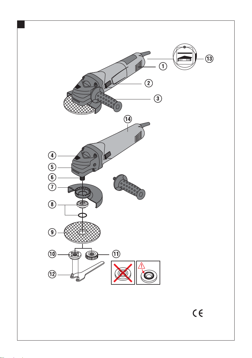
Operating controls and components 1
Ventilation slots
@
On / off switch
;
Vibration-absorbing side handle
=
Spindle lockbutton
%
Guard release button
&
Spindle
(
Guard
)
Clamping flange with O-ring
+
Abrasive cutting disc / abrasive grinding disc
§
Clamping nut
/
Kwik‑Lock quick-release clamping nut (optional)
:
Wrench
·
Speed preselection thumbwheel (DAG 125‑SE)
$
Non-slip grip surface
£
1.2 Explanation of the pictograms and other
information
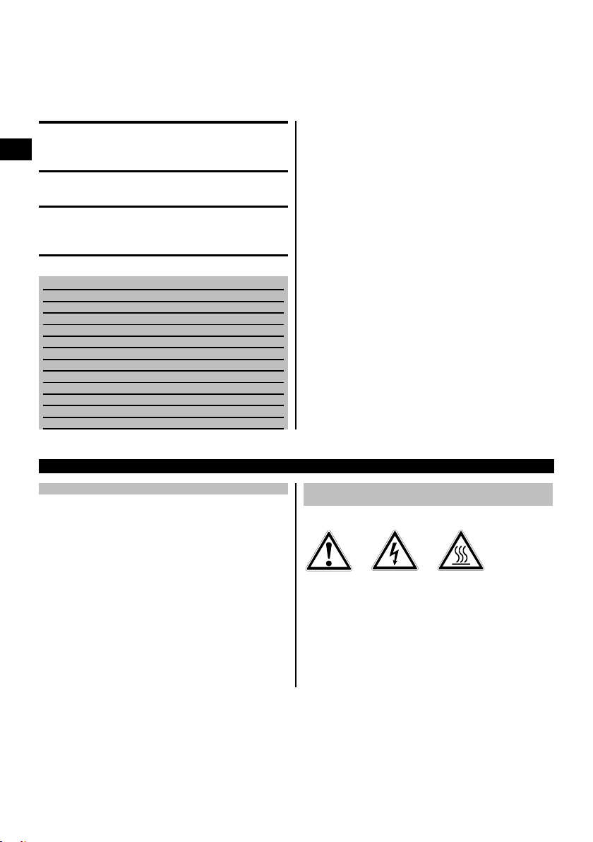
Warning signs
General
warning
Warning:
electricity
Warning: hot
surface
18
Printed: 24.04.2017 | Doc-Nr: PUB / 5138098 / 000 / 01Printed: 24.04.2017 | Doc-Nr: PUB / 5138098 / 000 / 02
Page 7
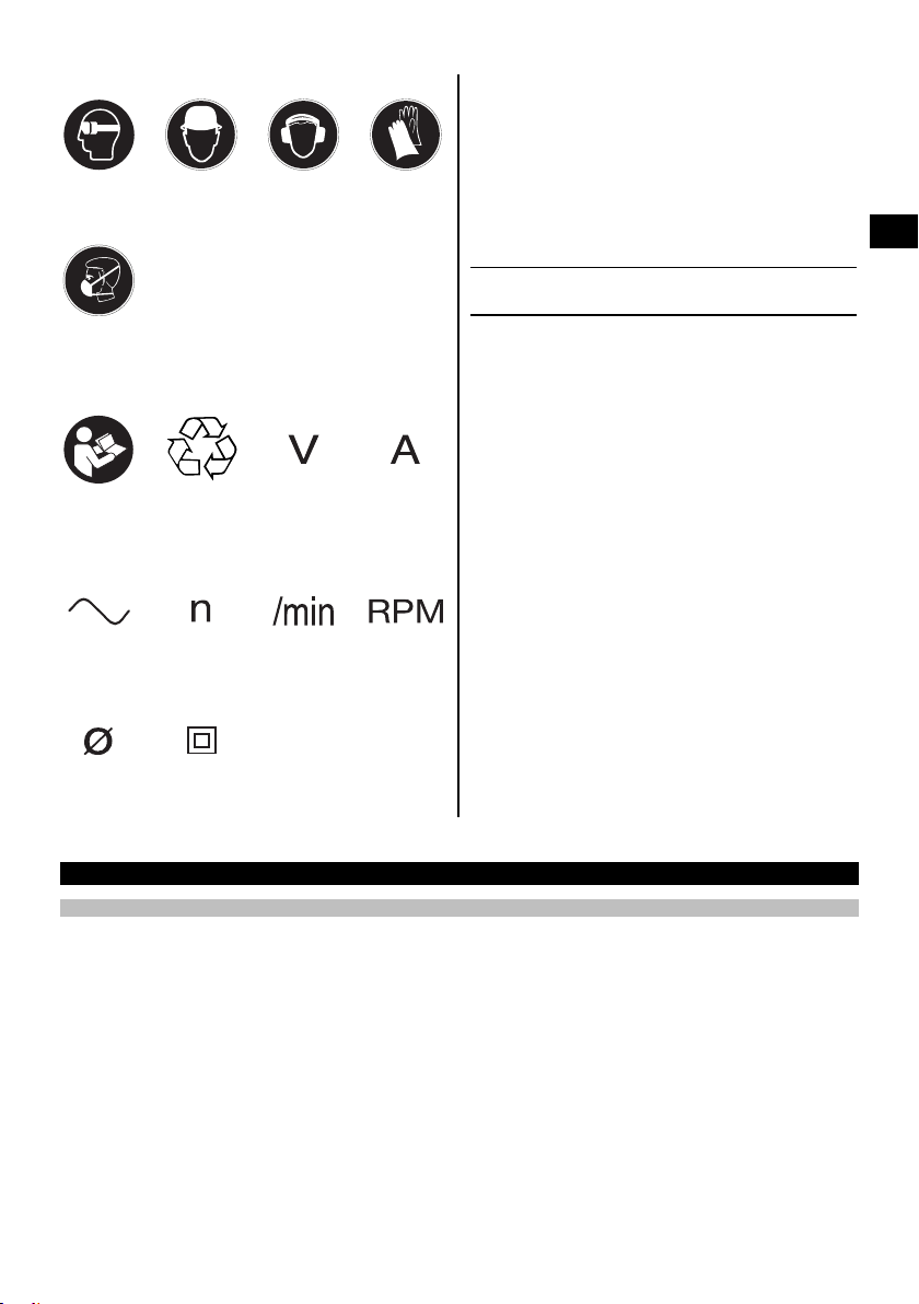
Obligation signs
Wear eye
protection
Wear
breathing
protection
Symbols
Wear a hard
hat
Wear ear
protection
Wear
protective
gloves
Location of identification data on the power tool
The type designation, item number, year of manufacture
and technical status can be found on the type identification plate on the machine or tool. The serial no. can
be found on the underside of the motor housing. Make
a note of this data in your operating instructions and
always refer to it when making an enquiry to your Hilti
representative or service department.
en
Type:
Serial no.:
Read the
operating
instructions
before use
Alternating
current
Diameter Double
Return waste
material for
recycling.
Rated speed Revolutions
insulated
Volts Amps
per minute
Revolutions
per minute
2 Description
2.1 Use of the product as directed
The power tool is designed for cutting and grinding metal and mineral materials without use of water. Use of a guide
carriage is mandatory for cutting stone.
The working environment may be as follows: construction site, workshop, renovation, conversion or new construction.
The power tool may be operated only when connected to a power supply providing a voltage and frequency in
compliance with the information given on its type identification plate.
Working with metals: Cutting, grinding.
Working with mineral materials: Cutting and slitting using the corresponding guard (DC-EX), grinding using the
corresponding guard (DG-EX).
Use only discs (abrasive grinding discs, abrasive cutting discs, etc.) that are approved for use at a speed of at least
11,000/min, with a maximum thickness of 6.4 mm (grinding discs) or 2.5 mm (cutting discs) and a diameter of max.125
mm.
Use only synthetic resin-bonded, fiber-reinforced grinding discs or cutting discs approved for use at a permissible
peripheral speed of at least 80 m/sec.
The power tool may be used only for dry cutting or grinding.
When grinding stone, a vacuum cleaner equipped with a stone dust filter, e.g. a suitable Hilti vacuum cleaner, must be
used.
Printed: 24.04.2017 | Doc-Nr: PUB / 5138098 / 000 / 01Printed: 24.04.2017 | Doc-Nr: PUB / 5138098 / 000 / 02
19
Page 8

Working on materials hazardous to the health (e.g. asbestos) is not permissible.
Take the influences of the surrounding area into account. Do not use the power tool or appliance where there is a risk
of fire or explosion.
Nationally applicable industrial safety regulations must be observed.
To avoid the risk of injury, use only genuine Hilti accessories and insert tools.
Observe the information printed in the operating instructions concerning operation, care and maintenance.
The power tool is designed for professional use and may be operated, serviced and maintained only by trained,
authorized personnel. This personnel must be informed of any special hazards that may be encountered. The power
en
tool and its ancillary equipment may present hazards when used incorrectlybyuntrainedpersonnelorwhenusednot
as directed.
Modification of the power tool or tampering with its parts is not permissible.
2.2 Switches
Lockable on / off switch with switch-on interlock
2.3 Speed preselection (only DAG 125‑SE)
The DAG 125‑SE version features steplessly adjustable speed preselection within the 2800-11000 r.p.m. range.
2.4 The items supplied in the cardboard box are:
1 Power tool with guard
1 Front cover (optional)
1 Vibration-absorbing side handle
1 Kwik‑Lock quick-release clamping nut (op-
tional)
1Flange
1Nut
1Wrench
1 Operating instructions
1 Cardboard box
2.5 Starting current limitation
The electronic starting current limiter reduces the starting current drawn by the power tool and thus prevents the
mainsfuseblowing.Italsoallowsthepowertooltostartsmoothly,without a jolt.
2.6 Constant-speed electronics
Electronic speed control keeps running speed almost constant irrespective of whether the power tool is idling or
running under load. Constant running speed helps ensure maximum efficiency.
2.7 ATC (Active Torque Control)
The electronics in the power tool detect situations where there is a risk of the disc sticking and prevent further rotation
of the drive spindle by switching the power tool off (does not prevent kickback). The switch must be released and
pressed again to restart the power tool.
2.8 Restart interlock
The power tool does not restart by itself when the switch is locked in the on-position and the power returns after an
interruption in the electric supply. The switch must first be released and then pressed again to restart.
2.9 Temperature-dependent motor protection
The temperature-dependent motor protection system prevents the power tool overheating by monitoring current input
and motor temperature.
In the event of motor overload due to application of excessive pressure to the disc, performance will drop noticeably
or the power tool may stop running (avoid stalling the power tool in this way).
Permissible overload cannot be given as a specific value as it depends on the temperature of the motor .
20
Printed: 24.04.2017 | Doc-Nr: PUB / 5138098 / 000 / 01Printed: 24.04.2017 | Doc-Nr: PUB / 5138098 / 000 / 02
Page 9

If the power tool has been overloaded, release the pressure applied and then allow it to run under no load for approx.
60 seconds.
2.10 Using extension cords
Use only extension cords of a type approved for the application and with conductors of adequate cross section. The
power tool may otherwise loose performance and the extension cord may overheat. Check the extension cord for
damage at regular intervals. Replace damaged extension cords.
Recommended minimum conductor cross section and max. cable lengths
Conductor cross
section
Mains voltage 100V 30 m 50 m
Mains voltage 110-
120 V
Mains voltage 220-
240 V
Do not use extension cords with 1.25 mm² or 16 AWG conductor cross sections.
2.11 Using extension cords outdoors
When working outdoors, use only extension cords that are approved and correspondingly marked for this application.
2.12 Using a generator or transformer
This power tool may be powered by a generator or transformer when the following conditions are fulfilled: The unit
must provide a power output in watts of at least twice the value printed on the type identification plate on the power
tool. The operating voltage must remain within +5% and -15% of the rated voltage at all times, frequency must be in
the 50 – 60 Hz range and never above 65 Hz, and the unit must be equipped with automatic voltage regulation and
starting boost.
Never operate other power tools or appliances from the generator or transformer at the same time. Switching other
power tools or appliances on and off may cause undervoltage and / or overvoltage peaks, resulting in damage to the
power tool.
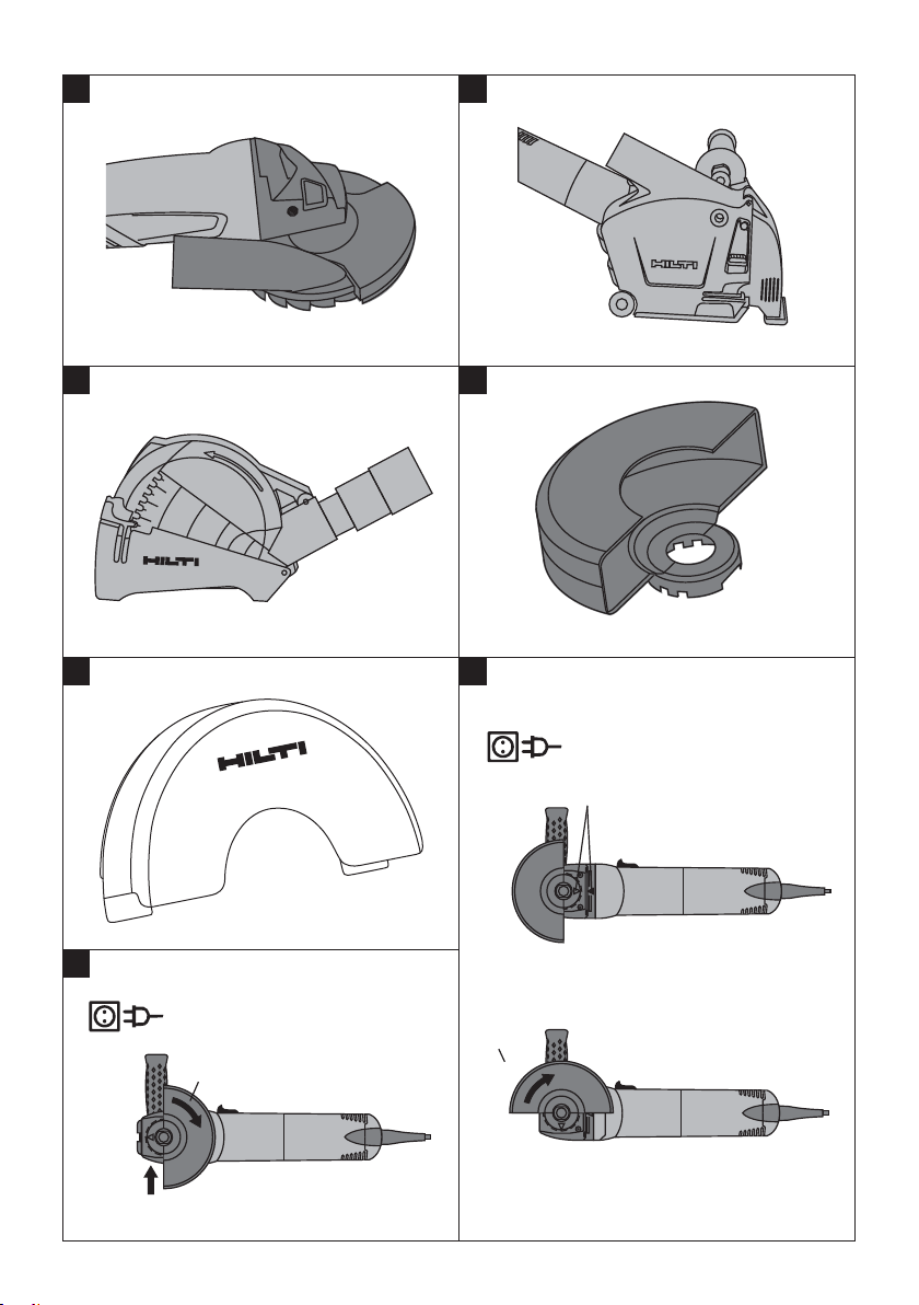
2.13 DG-EX 125/5" dust removal hood for grinding 2
The tool is suitable only for occasional use with diamond cup wheels for grinding mineral materials.
CAUTION
Use of this guard for working on metal is not permissible.
NOTE
It is recommended that a dust removal system consisting of matched components, i.e. dust removal hood and a
suitable Hilti vacuum cleaner, are used for grinding mineral materials, such as concrete or stone. These serve to
protect the operator and increase the life of the power tool and disc used.
1.5 mm² 2 mm² 2.5 mm² 3.5 mm²
20m 30m 40m 50m 75ft 125ft
50 m 100 m
14 AWG 12 AWG
en
2.14 DC‑EX 125/5"‑M dust removal hood with guide carriage for cutting and slitting 3
Cutting and slitting work on mineral materials may be carried out only when the power tool is equipped with a dust
removal hood with guide carriage.
CAUTION
Use of this guard for working on metal is not permissible.
NOTE
It is recommended that a dust removal system consisting of matched components, i.e. dust removal hood and a
suitable Hilti vacuum cleaner, are used for cutting and slitting mineral materials, such as concrete or stone. These
serve to protect the operator and increase the life of the power tool and discused.
2.15 DC‑EX 125/5"‑C compact dust removal hood for cutting 4
For cutting masonry and concrete.
Printed: 24.04.2017 | Doc-Nr: PUB / 5138098 / 000 / 01Printed: 24.04.2017 | Doc-Nr: PUB / 5138098 / 000 / 02
21
Page 10

CAUTION
Use of this guard for working on metal is not permissible.
NOTE
It is recommended that a dust removal system consisting of matched components, i.e. dust removal hood and a
suitable Hilti vacuum cleaner, are used for cutting and slitting mineral materials, such as concrete or stone. These
serve to protect the operator and increase the life of the power tool and discused.
en
2.16 Disc guard with side cover 5
CAUTION
When grinding with straight grinding discs and cutting with cutting discs in metalworking applications, use the
guard with cover plate.
2.17 Front cover for the disc guard 6
CAUTION
When grinding with straight grinding discs and cutting with cutting discs in metalworking applications, use the
guard with front cover.
3Consumables
Discs with a diameter of max. 125 mm, designed for a speed of 11000/min and a peripheral speed of 80 m/sec,
and with a maximum thickness of 6.4 mm (abrasive grinding discs) or 2.5 mm (abrasive cutting discs).
Discs Application Designation Material
Abrasive cutting disc Cutting, slitting AC‑D metal
Diamond cutting disc Cutting, slitting DC‑D mineral
Abrasive grinding disc Rough grinding AG‑D, AF‑D, AN‑D metal
Diamond grinding disc Rough grinding DG‑CW mineral
Assignment of discs to the equipment used
Item Equipment
AGuard XXXXXX
B Front cover (in combin-
ation with A)
C Guard with cover plate
(optional for A, B)
D DG‑EX 125/5" surface
guard
E DC‑EX 125/5"-C com-
pact guard (in combination with A)
F DC‑EX 125/5"M cut-
ting guard for mineral
materials
GDC‑EXSLcuttingad-
apter (in combination
with F)
HSidehandle XXXXXX
I DC BG 125 hoop
handle (optional for H)
KClampingnut XXXXXX
L Clamping flange X X X X X X
M Kwik-Lock (optional forK)XXXX
AC‑D AG-D
X
X
----
-----
-----
-----
XXXXXX
----
----
AF-D AN-D
DG‑CW DC‑D
X
-
X
X
-
X
X
X
X
22
Printed: 24.04.2017 | Doc-Nr: PUB / 5138098 / 000 / 01Printed: 24.04.2017 | Doc-Nr: PUB / 5138098 / 000 / 02
Page 11

4 Technical data
Right of technical changes reserved.
Power tool
Rated current / power
input
DCG 125‑S DAG 125‑S DAG 125‑SE
Rated voltage 220 / 230
V: 6.4 A / 1,400 W
Rated voltage 110 V:
12.2 A / 1,200 W
Rated voltage 220 / 230
V: 5.0 A / 1,100 W
Rated voltage 110 V:
10.2 A / 1,050 W
Rated voltage 220 / 230
V: 5.0 A / 1,100 W
Rated voltage 110 V:
10.2 A / 1,050 W
Rated frequency 50 / 60 Hz 50 / 60 Hz 50 / 60 Hz
Rated speed 11,000/min 11,000/min 2,800…11,000/min
Max. washer diameter Diameter 125 mm Diameter 125 mm Diameter 125 mm
Dimensions (L x H x W)
without hood
Weight in accordance
304 mm x 103 mm x
82 mm
289 mm x 103 mm x
82 mm
289 mm x 103 mm x
82 mm
2.4 kg 2.2 kg 2.2 kg
with EPTA procedure
01/2003
Information about the power tool and applications
Drive spindle thread (arbor size) M 14
Spindle length 22 mm
Protection class as per EN / IEC Protection class II (double insulated)
NOTE
The vibration emission level given in this information sheet has been measured in accordance with a standardised test
giveninEN60745andmaybeusedtocompareonetoolwithanother.Itmaybeused for a preliminary assessment
of exposure. The declared vibration emission level represents the main applications of the tool. However if the tool is
used for different applications, with different accessories or poorly maintained, the vibration emission may differ. This
may significantly increase the exposure level over the total working period. An estimation of the level of exposure to
vibration should also take into account the times when the tool is switched off or when it is running but not actually
doing the job. This may significantly reduce the exposure level over the total working period. Identify additional safety
measures to protect the operator from the effects of vibration such as: maintain the tool and the accessories, keep
the hands warm, organisation of work patterns.
Noise information (as perEN 60745‑1):
Typical A-weighted sound power level, DCG 125 101 dB (A)
Typical A-weighted emission sound pressure level,
90 dB (A)
DCG 125
Typical A-weighted sound power level, DAG 125 98 dB (A)
Typical A-weighted emission sound pressure level,
87 dB (A)
DAG 125
Uncertainty for the given sound level 3 dB (A)
en
Vibration information in accordance with EN 60745‑1
Triaxial vibration values (vibration vector sum) for the
measured in accordance with EN 60745‑2‑3
DAG 125‑S / DAG 125‑SE
Surface grinding with the standard side handle, a
Surface grinding with the vibration-absorbing side
handle, a
h,AG
Surface grinding with the hoop handle, a
h,AG
h,AG
5.8 m/s²
4.6 m/s²
5.9 m/s²
Uncertainty (K) 1.5 m/s²
Triaxial vibration values (vibration vector sum) for the
measured in accordance with EN 60745‑2‑3
DCG 125‑S
Surface grinding with the standard side handle, a
Printed: 24.04.2017 | Doc-Nr: PUB / 5138098 / 000 / 01Printed: 24.04.2017 | Doc-Nr: PUB / 5138098 / 000 / 02
h,AG
6.4 m/s²
23
Page 12

Surface grinding with the vibration-absorbing side
handle, a
h,AG
Surface grinding with the hoop handle, a
h,AG
5.7 m/s²
5.8 m/s²
Uncertainty (K) 1.5 m/s²
Additional information Other applications, such as cutting, may produce vibra-
tion values that deviate from the given values.
en
5 Safety instructions
5.1 General Power Tool Safety Warnings
a)
WARNING
Read all safety warnings and all instructions. Fail-
ure to follow the warningsand instructions may result
in electric shock, fire and/or serious injury. Save all
warnings and instructions for future reference.
The term “power tool” in the warnings refers to
your mains-operated (corded) power tool or batteryoperated (cordless) power tool.
5.1.1Workareasafety
a) Keep work area clean and well lit. Cluttered or dark
areas invite accidents.
b) Do not operate power tools in explosive atmo-
spheres, such as in the presence of flammable
liquids, gases or dust. Power tools create sparks
which may ignite the dust or fumes.
c) Keep children and bystanders away while operat-
ing a power tool. Distractions can cause you to lose
control.
5.1.2 Electrical safety
a) Power tool plugs must match the outlet. Never
modify the plug in any way. Do not use any adapter plugs with earthed (grounded) power tools.
Unmodified plugs and matching outlets will reduce
risk of electric shock.
b) Avoid body contact with earthed or grounded
surfaces, such as pipes, radiators, ranges and
refrigerators. There is an increased risk of electric
shock if your body is earthed or grounded.
c) Do not expose power tools to rain or wet condi-
tions. Water entering a power tool will increase the
risk of electric shock.
d) Do not abuse the cord. Never use the cord for
carrying, pulling or unplugging the power tool.
Keep cord away from heat, oil, sharp edges or
moving parts. Damaged or entangled cords increase
theriskofelectricshock.
e) When operating a power tool outdoors, use an
extension cord suitable for outdoor use. Use of
a cord suitable for outdoor use reduces the risk of
electric shock.
f) If operating a power tool in a damp location is
unavoidable, use a residual current device (RCD)
protected supply. Use of an RCD reduces the risk
of electric shock.
5.1.3 Personal safety
a) Stay alert, watch what you are doing and use
common sense when operating a power tool. Do
not use a power tool while you are tired or under
the influence of drugs, alcohol or medication. A
moment of inattention while operating power tools
may result in serious personal injury.
b) Use personal protective equipment. Always wear
eye protection. Protective equipment such as dust
mask, non-skid safety shoes, hard hat, or hearing
protectionused forappropriate conditions will reduce
personal injuries.
c) Prevent unintentional starting. Ensure the switch
is in the off‐position before connecting to power
source and/or battery pack, picking up or carrying
the tool. Carrying power tools with your finger on the
switch or energising power tools that have the switch
on invites accidents.
d) Remove any adjusting key or wrench before turn-
ing the power tool on. A wrench or a key left attached to a rotating part of the power tool may result
in personal injury.
e) Do not overreach. Keep proper footing and bal-
ance at all times. This enables better control of the
power tool in unexpected situations.
f) Dress properly. Do not wear loose clothing or
jewellery. Keep your hair, clothing and gloves
away from moving parts. Loose clothes, jewellery
or long hair can be caught in moving parts.
g) If devices are provided for the connection of dust
extraction and collection facilities, ensure these
are connected and properly used. Use of dust
collection can reduce dust-related hazards.
5.1.4 Power tool use and care
a) Do not force the power tool. Use the correct
power tool for your application. The correct power
tool will do the job better and safer at the rate for
which it was designed.
b) Do not use the power tool if the switch does not
turn it on and off. Any power tool that cannot be
controlled with the switch is dangerous and must be
repaired.
c) Disconnect the plug from the power source
and/or the battery pack from the power tool
before making any adjustments, changing
accessories, or storing power tools. Such
preventive safety measures reduce the risk of
starting the power tool accidentally.
24
Printed: 24.04.2017 | Doc-Nr: PUB / 5138098 / 000 / 01Printed: 24.04.2017 | Doc-Nr: PUB / 5138098 / 000 / 02
Page 13

d) Store idle power tools out of the reach of chil-
dren and do not allow persons unfamiliar with the
power tool or these instructions to operate the
power tool. Power tools are dangerous in the hands
of untrained users.
e) Maintain power tools. Check for misalignment or
binding of moving parts, breakage of parts and
any other condition that may affect the power
tool’s operation. If damaged, have the power tool
repaired before use. Many accidents are caused by
poorly maintained power tools.
f) Keep cutting tools sharp and clean. Properly main-
tained cutting tools with sharp cutting edges are less
likely to bind and are easier to control.
g) Use the power tool, accessories and tool bits etc.
in accordance with these instructions, taking into
account the working conditions and the work to
be performed. Use of the power tool for opera-
tions different from those intended could result in a
hazardous situation.
5.1.5 Service
a) Have your power tool servicedby a qualified repair
person using only identical replacement parts.
This will ensure that the safety of the power tool is
maintained.
5.2 Safety warnings for abrasive cutting-off
operations
a) This power tool is intended to function as a cut-
off tool. Read all safety warnings, instructions,
illustrations and specifications provided with this
power tool. Failure to follow all instructions listed
below may result in electric shock, fire and/or serious
injury.
b) Operations such as sanding, wire brushing or
polishing are not recommended to be performed
with this power tool Operations for which the power
tool was notdesigned may create a hazard and cause
personal injury.
c) Do not use accessories which are not specifically
designed and recommended by the tool manufacturer. Just because the accessory can be attached
to your power tool, it does not assure safe operation.
d) The rated speed of the accessory must be at
least equal to the maximum speed marked on the
power tool. Accessories running faster than their
rated speed can break and fly apart.
e) The outside diameter and the thickness of your
accessory must be within the capacity rating of
your power tool. Incorrectly sized accessories can-
not be adequately guarded or controlled.
f) Threaded mounting of accessories must match
the grinder spindle thread. For accessoriesmounted by flanges, the arbour hole of the accessory
must fit the locating diameter of the flange. Ac-
cessories that do not match the mounting hardware
of the power tool will run out of balance, vibrate
excessively and may cause loss of control.
g) Do not use a damaged accessory. Before each
use inspect the accessory such as abrasive
wheels for chips and cracks, backing pad for
cracks, tear or excess wear, wire brush for loose
or cracked wires. If power tool or accessory
is dropped, inspect for damage or install an
undamaged accessory. After inspecting and
installing an accessory, position yourself and
bystanders away from the plane of the rotating
accessory and run the power tool at maximum
no-load speed for one minute. Damaged
accessories will normally break apart during this test
time.
h) Wear personal protective equipment. Depending
on application, use face shield, safety goggles or
safety glasses. As appropriate, wear dust mask,
hearing protectors, gloves and workshop apron
capable of stopping small abrasive or workpiece
fragments.
stopping flying debris generated by various operations. The dust mask or respirator must be capable of
filtrating particles generated by your operation. Prolonged exposure to high intensity noise may cause
hearing loss.
i) Keep bystanders a safe distance away from
work area. Anyone entering the work area must
wear personal protective equipment. Fragments
of workpiece or of a broken accessory may fly
away and cause injury beyond immediate area of
operation.
j) Hold the power tool byinsulated grippingsurfaces
only, when performing an operation where the
cutting accessory may contact hidden wiring or
its own cord. Cutting accessory contacting a "live"
wire may make exposed metalparts of the power tool
"live" and could give the operator an electric shock.
k) Position the cord clear of the spinning accessory.
If you lose control, the cord may be cut or snagged
andyourhandorarmmaybepulledintothespinning
accessory.
l) Never lay the power tool down until the access-
ory has come to a complete stop. The spinning
accessory may grab the surface and pull the power
tool out of your control.
m) Do not run the power tool while carrying it at your
side. Accidental contact with the spinning accessory
could snag your clothing, pulling the accessory into
your body.
n) Regularly clean the power tool’s air vents. The
motor’s fan will draw the dust inside the housing
and excessive accumulation of powdered metal may
cause electrical hazards.
o) Do not operate the power tool near flammable
materials. Sparks could ignite these materials.
p) Do not use accessories that require liquid
coolants. Using water or other liquid coolants may
result in electrocution or shock.
5.3 Kickback and related warnings
Kickback is a sudden reaction to a pinched or snagged
rotating wheel, backing pad, brush or any other accessory. Pinching or snagging causes rapid stalling of the
rotating accessory which in turn causes the uncontrolled
The eye protection must be capable of
en
Printed: 24.04.2017 | Doc-Nr: PUB / 5138098 / 000 / 01Printed: 24.04.2017 | Doc-Nr: PUB / 5138098 / 000 / 02
25
Page 14

power tool to be forced in the direction opposite of the
accessory’s rotation at the point of the binding.
For example, if an abrasive wheel is snagged or pinched
by the workpiece, the edge of the wheel that is entering
into the pinch point can dig into the surface of the material
causing the wheel to climb out or kick out. The wheel may
either jump toward or away from the operator, depending
on direction of the wheel’s movement at the point of
pinching. Abrasive wheels may also break under these
en
conditions.
Kickback is the result of power tool misuse and/or incorrect operating procedures or conditions and can be
avoided by taking proper precautions as given below.
a) Maintain a firm grip on the power tool and po-
sition your body and arm to allow you to resist
kickback forces. Always use auxiliary handle, if
provided, for maximum control over kickback or
torque reaction during start-up. The operator can
control torque reactions or kickback forces, if proper
precautions are taken.
b) Never place your hand near the rotating access-
ory. Accessory may kickback over your hand.
c) Do not position your body in the area where power
tool will move if kickback occurs. Kickback will
propel the tool in direction opposite to the wheel’s
movement at the point of snagging.
d) Use special care when working corners, sharp
edges etc. Avoid bouncing and snagging the accessory. Corners, sharp edges or bouncing have a
tendency to snag the rotating accessory and cause
loss of control or kickback.
e) Do not attach a saw chain woodcarving blade or
toothed saw blade. Such blades create frequent
kickback and loss of control.
5.4 Safety warnings specific for grinding and
abrasive cutting-off operations
a) Use only wheel types that are recommended for
your power tool and the specific guard designed
for the selected wheel. Wheels for which the power
tool was not designed cannot be adequately guarded
and are unsafe.
b) The grinding surface of centre depressed wheels
must be mounted below the plane of the guard lip.
An improperly mounted wheel that projects through
the plane of the guard lip cannot be adequately
protected.
c) The guardmust be securely attachedto the power
tool and positioned for maximum safety, so the
least amount of wheel is exposed towards the operator. The guard helps to protect operator from
broken wheel fragments, accidental contact with
wheel and sparks that could ignite clothing.
d) Wheels must be used only for recommended ap-
plications. For example: do not grind with the side
of cut-off wheel. Abrasive cut-off wheels are inten-
ded for peripheral grinding, side forces applied to
these wheels may cause them to shatter.
e) Always use undamaged wheel flanges that are of
correct size and shape for your selected wheel.
Proper wheel flanges support the wheel thus reducing the possibility of wheel breakage. Flanges for
cut-off wheels may be different from grinding wheel
flanges.
f) Do not use worn down wheels from larger power
tools. Wheel intended for larger power tool is not
suitable for the higher speed of a smaller tool and
may burst.
5.5 Additional safety warnings specific for abrasive
cutting-off operations
a) Do not "jam" the cut-off wheel or apply excessive
pressure. Do not attempt to make an excessive
depth of cut. Overstressing the wheel increases the
loading and susceptibility to twisting or binding of
the wheel in the cut and the possibility of kickback or
wheel breakage.
b) Do not position your body in line with and behind
the rotating wheel. When the wheel, at the point
of operation, is moving away from your body, the
possible kickback may propel the spinning wheel
and the power tool directly at you.
c) When wheel is binding or when interrupting a cut
for any reason, switch off the power tool and hold
the power tool motionless until the wheel comes
to a complete stop. Never attempt to remove the
cut-off wheel from the cut while the wheel is in
motion otherwise kickback may occur.Investigate
and take corrective action to eliminate the cause of
wheel binding.
d) Do not restart the cutting operation in the work-
piece. Let the wheel reach full speed and carefully
re-enter the cut. The wheel may bind, walk up or
kickback if the power tool is restarted in the workpiece.
e) Support panels or any oversized workpiece to
minimize the risk of wheel pinching and kickback.
Large workpieces tend to sag under their own weight.
Supports must be placed under the workpiece near
the line of cut and near the edge of the workpiece on
both sides of the wheel.
f) Use extra caution when making a "pocket cut"
into existing walls or other blind areas. The protruding wheel may cut gas or water pipes, electrical
wiring or objects that can cause kickback.
5.6 Additional safety instructions
5.6.1 Personal safety
a) Always hold the power tool securely with both
hands on the grips provided. Keep the grips dry,
clean and free from oil and grease.
b) Breathing protection must be worn if the power
tool is used without a dust removal system for
work that creates dust.
c) Improve the blood circulation in your fingers by
relaxing your hands and exercising your fingers
during breaks between working.
d) Avoid touching rotating parts. Switch the power
tool on only after bringing it into position at the
26
Printed: 24.04.2017 | Doc-Nr: PUB / 5138098 / 000 / 01Printed: 24.04.2017 | Doc-Nr: PUB / 5138098 / 000 / 02
Page 15

workpiece. Touching rotating parts, especially rotating insert tools, may lead to injury.
e) Always lead the supply cord and extension cord
away from the power tool to the rear while working. This helps to avoid tripping over the cord while
working.
f) When grinding with straight grinding discs and
cutting with cutting discs in metalworking applications, use the guard with cover plate.
g) Children must be instructed not to play with the
power tool.
h) The power tool is not intended for use by children,
by debilitated persons or those who have received
no instruction or training.
i) Do not use the power tool if it starts with a jolt.This
may be an indication that the electronic control unit
is defective. Have the tool repaired at an authorized
Hilti service center right away.
j) Dust from material such as paint containing lead,
some wood species, minerals and metal may be
harmful. Contact with or inhalation of the dust may
cause allergic reactions and/or respiratory diseases
to the operator or bystanders. Certain kinds of dust
are classified as carcinogenic such as oak and beech
dust especially in conjunctionwith additives for wood
conditioning (chromate, wood preservative). Material
containing asbestos must only be treated by specialists. Where the use of a dust extraction device is
possible it shall be used. To achieve a high level
of dust collection, use a suitable vacuum cleaner
of the type recommended by Hilti for wood dust
and/or mineral dust together with this tool. Ensure
that the workplace is well ventilated. The use of a
dust mask of filter class P2 is recommended. Follow national requirements for the materials you
want to work with.
5.6.2 Power tool use and care
a) Grinding discs must be stored and handled care-
fully in accordance with the manufacturer’s instructions.
b) Check that the grinding disc is fitted in accord-
ance with the manufacturer’s instructions.
c) If use of a spacer ring or other intermediate part is
specifiedand the part is supplied with the grinding
disc, check to ensure that the part is fitted.
d) Never use the power tool without the guard.
e) The workpiece must be fixed securely in place.
f) Before use, check that the cutting disc has been
fitted correctly and the clamping nut tightened.
Then allow the power tool to run for 60 seconds
under no load while holding it securely. Switch off
the power tool immediately if significant vibration
or any other faults are noticed. Should this occur,
examine the power tool in order to determine the
cause.
g) Do not use cutting discs for grinding.
h) Take steps to ensure that flying sparks from the
power tool do not present a hazard, i.e. by striking
yourself or other persons. Adjust the position of
the guard accordingly.
i) After disc breakage, or if the power tool is
dropped, falls or suffers other mechanical
damage, it must be checked at a Hilti Service
Center.
5.6.3 Electrical safety
en
a) Before beginning work, check the working area
(e.g. using a metal detector) to ensure that no
concealed electric cables or gas and water pipes
are present. External metal parts of the power tool
may become live, for example, when an electric cable
is damaged accidentally. This presents a serious risk
of electric shock.
b) Check the power tool’s supply cord at regular
intervals and have it replaced by a qualified specialist if found to be damaged. If the power tool’s
supply cord is damaged it must be replaced with
a specially-prepared supply cord available from
Hilti Customer Service. Check extension cords
at regular intervals and replace them if found to
be damaged. Do not touch the supply cord or
extension cord if it is damaged while working.
Disconnect the supply cord plug from the power
outlet. Damaged supply cords or extension cords
present a risk of electric shock.
c) Dirty or dusty power tools which have been used
frequently for work on conductive materials
should be checked at regular intervals at a Hilti
Service Center. Under unfavorable circumstances,
dampness or dust adhering to the surface of
the power tool, especially dust from conductive
materials, may present a risk of electric shock.
d) When working outdoors with an electric tool
check to ensure that the tool is connected to the
electric supply by way of a ground fault circuit
interrupter (RCD) with a rating of max. 30 mA
(tripping current). Use of a ground fault circuit
interrupter reduces the risk of electric shock.
e) Use of a ground fault circuit interrupter (RCD
residual current device) with a maximum tripping
current of 30 mA is recommended.
5.6.4 Work area
a) Ensure that the workplace is well lit.
b) Ensure that the workplace is well ventilated. Ex-
posure to dust at a poorly ventilated workplace may
result in damage to the health.
c) If the work involves breaking right through, take
the appropriate safety measures at the opposite
side. Parts breaking away could fall out and / or fall
down and injure other persons.
d) Slits cut in loadbearing walls of buildings or other
structures may influence the statics of the structure,
especially when steel reinforcing bars or load-bearing
components are cut through. Consult the structural
Printed: 24.04.2017 | Doc-Nr: PUB / 5138098 / 000 / 01Printed: 24.04.2017 | Doc-Nr: PUB / 5138098 / 000 / 02
27
Page 16

engineer, architect, or person in charge of the
building project before beginning the work.
5.6.5 Personal protective equipment
en
The user and any other persons in the vicinity must
wear suitable eye protection, a hard hat, ear protec-
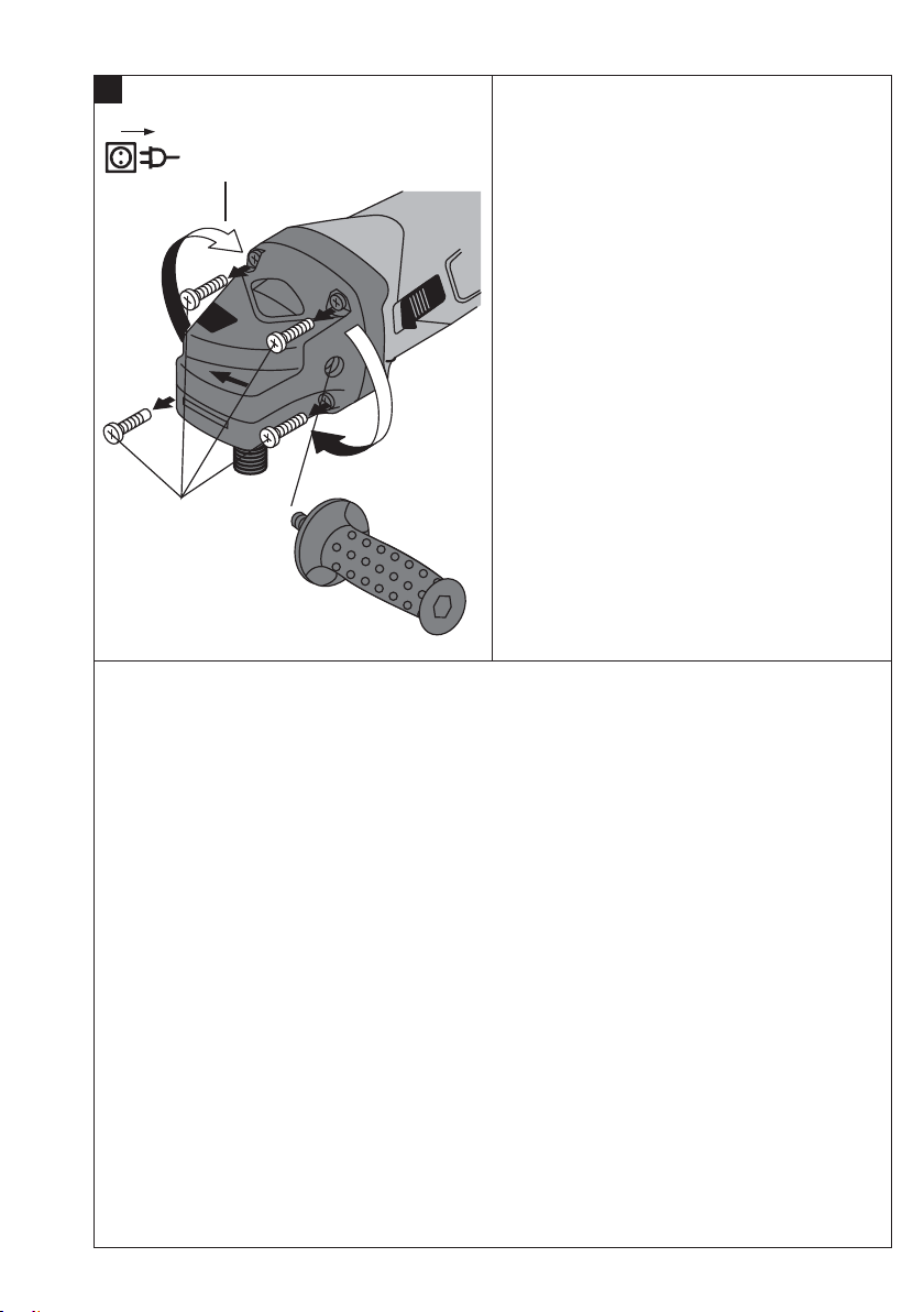
6Beforeuse
DANGER
Disconnect the plug from the power source before
making any adjustments, changing accessories, or
storing the tool. Such preventive safety measures
reduce the risk of starting the tool accidentally.
CAUTION
Wear gloves when fitting or removing parts, when
making adjustments or when remedying malfunctions.
WARNING
Never use the power tool without the guard.
CAUTION
Before using another accessory that is recommended for the angle grinder in conjunction with the
angle grinders mentioned above, read the operating instructions for the applicable angle grinder and
observe all instructions.
6.1 Fitting the side handle
WARNING
The side handle must be fitted for all types of work.
The side handle may be screwed onto the power tool on
the right or left.
6.2 Guard
CAUTION
Adjust the position of the guard to suit the requirements of the work being done.
CAUTION
Theclosedsideoftheguardmustalwaysfacethe
operator.
tion, protective gloves and breathing protection while
the power tool is in use.
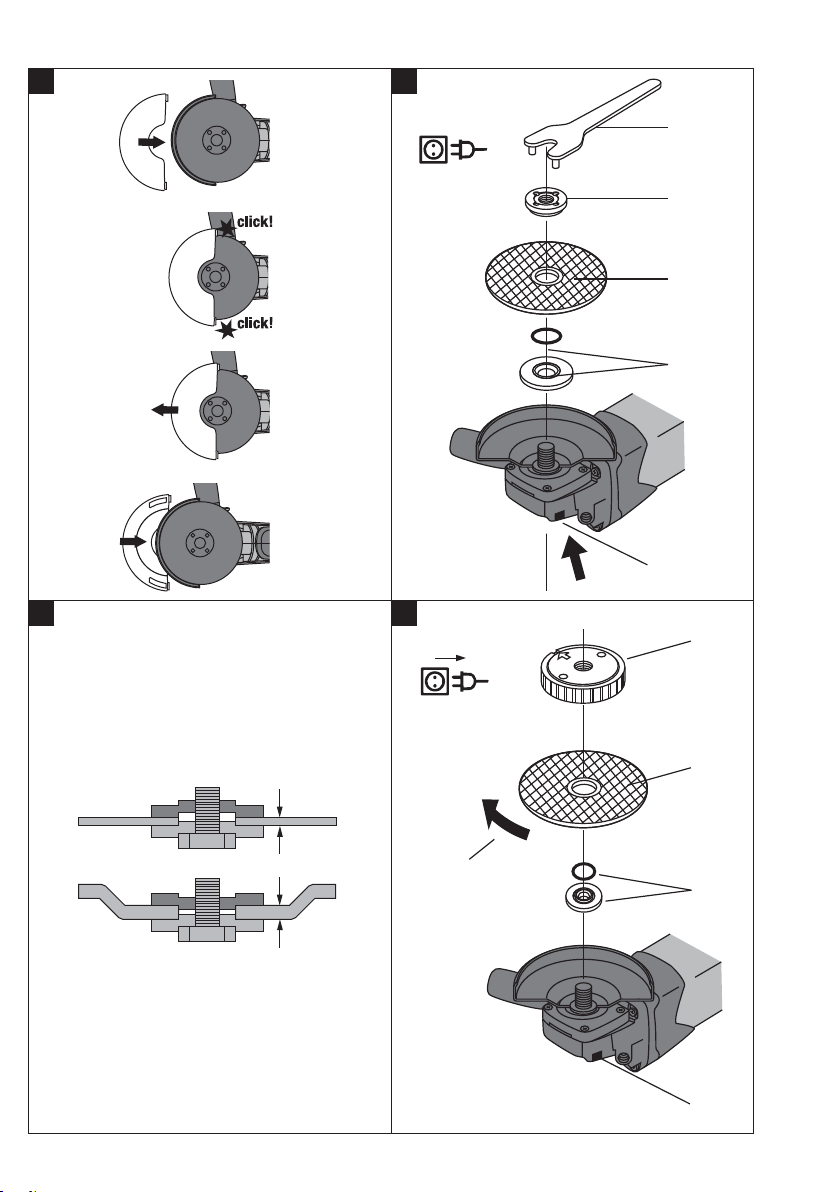
6.2.1 Fitting the guard or guard with cover plate 8
NOTE
The keyed locating lug on the guard ensures that only
a guard designed for use with the power tool can be
fitted. The keyed locating lug also prevents the guard
from coming into contact with the disc.
1. Fit the guard onto the drive spindle collar so that the
two triangular marks on the guard and on the power
tool in alignment.
2. Press the guard onto the drive spindle collar; press
the guard release button and then rotate the guard
until it engages and the guard release button jumps
back to its outset position.
6.2.2 Adjusting the guard 7
1. Press the guard release button and then rotate the
guard until it engages in the desired position.
6.2.3 Removing the guard or guard with cover plate
1. Press the guard release button and then rotate the
guard until the triangular marks on the guard and
the power tool are in alignment.
2. Lift off the guard.
6.2.4 Fitting and removing the front cover 9
1. Press the front cover onto the standard guard, with
the closed side positioned as shown in the illustration, until it engages.
2. To remove the front cover, release the catch and
then pull the front cover away from the standard
guard.
6.3 Fitting and removing the disc
DANGER
Check that the speed rating printed on the cutting
or grinding disc is equal to or higher than the rated
speed of the power tool.
28
Printed: 24.04.2017 | Doc-Nr: PUB / 5138098 / 000 / 01Printed: 24.04.2017 | Doc-Nr: PUB / 5138098 / 000 / 02
Page 17

DANGER
Check the condition of the grinding disc before using it. Do not use discs that are broken, cracked or
damaged in any way.
NOTE
Diamond discs must be replaced when the cutting or
grinding performance drops significantly. This generally
is the case when the segments reach a height of less
than 2 mm. Other discs must be replaced when the
cutting performance drops significantly or other parts of
the angle grinder (not the disc) come into contact with
the material you are working on. Abrasive discs generally
have to be replaced when the durability date has been
reached.
1. CAUTION The clamping flange is equipped with
an O-ring. If this O-ring is missing, the clamping
flange must be replaced.
Fit the clamping flange onto the drive spindle.
2. Fit the insert tool.
3. Screw on the clamping nut corresponding to the
type of disc fitted.
4. CAUTION Do not press the spindle lockbutton
before the drive spindle has stopped rotating.
Press the spindle lockbutton and hold it in this
position.
5. Use the wrench to tighten the clamping nut securely
and then release the spindle lockbutton.
6. To remove the disc from the power tool, follow the
instructions for fitting the disc but carry out the steps
in the reverse order.
6.4 Insert tool with Kwik-Lock quick-release nut
CAUTION
When operating the power tool, take care to ensure
that the Kwik-Lock nut does not come into contact
with the work surface. Do not use a damaged KwikLock nut.
NOTE
The Kwik-Lock nut can be used instead of the clamping
nut. No tools are then required for changing cutting discs.
6.4.1 Fitting and removing the insert tool using the
Kwik-Lock quick-release nut
NOTE
The arrow on the upper surface of the nut must be within
the index marks. If the arrow is not within the index marks
when the Kwik-Lock nut is tightened it will be impossible
toreleasethenutbyhand.Inthiscase,usethepin
wrench to release the Kwik-Lock nut (do not use a pipe
wrench!).
1. Clean the clamping flange and Kwik-Lock nut.
2. CAUTION The clamping flange is equipped with
an O-ring. If this O-ring is missing, the clamping
flange must be replaced.
Fit the clamping flange onto the drive spindle.
3. Fit the insert tool.
4. Screw the Kwik-Lock nut onto the spindle until it
contacts the grinding disc (the side with the lettering
should be visible after the nut is screwed on).
5. CAUTION Do not press the spindle lockbutton
before the drive spindle has stopped rotating.
Press the spindle lockbutton and hold it in this
position.
6. Turn the grinding disc firmly by hand in a clockwise direction until the Kwik-Lock nut is tightened
securely and then release the spindle lockbutton.
7. To remove this, follow the instructions for fitting the
module but carry out the steps in the reverse order.
6.5 Rotating the gearing section
NOTE
To allow the tool to be used safely and without fatigue
in all positions (e.g. on / off switch facing upwards), the
gearing section can be rotated to one of four positions at
90° intervals.
1. Clean the tool.
2. Removethesidehandlefromthetool.
3. Remove the four screws from the gearing section.
4. Rotate the gearing section to the desired position
without pulling it away from the tool.
5. Secure the gearing section by inserting and tightening the four screws.
6. Fit the side handle.
en
7Operation
NOTE
Adjust the position of the guard to suit the requirements
of the work being done.
DANGER
Wear ear protectors. Exposure to noise can cause hear-
ing loss.
Printed: 24.04.2017 | Doc-Nr: PUB / 5138098 / 000 / 01Printed: 24.04.2017 | Doc-Nr: PUB / 5138098 / 000 / 02
CAUTION
The closed side of the guard must always face the
operator.
WARNING
Test new cutting or grinding discs by allowing them
to run at maximum speed in a protected area for at
least 30 seconds.
WARNING
Do not use the power tool if it starts with a jolt.This
may be an indication that the electronic control unit is
29
Page 18

defective. Have the tool repaired at an authorized Hilti
service center right away.
WARNING
Slits cut in loadbearing walls of buildings or other structures may influence the statics of the structure, especially
when steel reinforcing bars or load-bearing components
are cut through. Consult the structural engineer, ar-
chitect, or person in charge of the building project
en
before beginning the work.
WARNING
The electric supply voltage must comply with the information given on the type identification plate on the
power tool. 230 V power tools may also be connected
to a 220 V supply.
WARNING
Always use the side handle with the power tool (use
the hoop handle as an option).
CAUTION
Use clamps or a vice to hold the workpiece securely.
WARNING
Cutting or grinding may cause splintering of the material.
Wear eye protection.
CAUTION
Breathing protection must be worn if the power tool
is used without a dust removal system for work that
creates dust.
WARNING
Avoid touching rotating parts. Switch the power tool
on only after bringing it into position at the workpiece.
Touching rotating parts, especially rotating insert tools,
may lead to injury.
CAUTION
The insert tool may get hot during use. Wear protective
gloves when changing insert tools.
CAUTION
In accordance with the applications for which it is designed, the power tool produces a high torque. Always
use the side handle and hold the power tool with both
hands. The user must be prepared for sudden sticking
and stalling of the insert tool.
CAUTION
Working on the material may cause it to splinter. Wear
eye protection and protective gloves. Wear breathing
protection if no dust removal system is used. Splin-
tering material presents a risk of injury to the eyes and
body.
WARNING
Reduce the load on the power tool by avoiding tilting the disc in the kerf when cutting. Thediscmay
otherwise break, or the power tool may kick back or stall.
CAUTION
Improve the blood circulation in your fingers by relaxing your hands and exercising your fingers during
breaks between working.
WARNING
Keep inflammable materials away from the working
area.
7.1 Rough grinding
CAUTION
Never use abrasive cutting discs for grinding.
Best results are obtained when the disc maintains an
angle of 5° to 30° with the working surface when grinding.
Move the power tool to and fro while applying moderate
pressure. This will avoid overheating and discoloration of
the workpiece and ensure an even surface finish.
7.2 Cutting
When cutting, apply moderate feed pressure and do not
tilt the power tool or, respectively, the cutting disc (hold
at approx. 90° to the surface being cut). For best results,
start cutting at the smallest cross section when cutting
profiles and square tube.
7.3 Switching on / off
7.3.1 Switching on
1. Plug the supply cord into the power outlet.
2. Press the rear section of the on / off switch.
3. Slide the on / off switch forward.
4. Lock the on / off switch.
7.3.2 Switching off
Press the rear section of the on / off switch. The on / off
switch jumps back to the off-position.
7.4 Restart interlock
NOTE
If the power tool is unplugged from the electric supply
while the on / off switch is locked in the on-position and
subsequently plugged back into the electric supply, it
will not restart. The switch lock must be released while
the power tool is disconnected from the electric supply
before the supply cord is again plugged into the power
outlet.
30
Printed: 24.04.2017 | Doc-Nr: PUB / 5138098 / 000 / 01Printed: 24.04.2017 | Doc-Nr: PUB / 5138098 / 000 / 02
Page 19

8 Care and maintenance
CAUTION
Disconnect the mains plug from the power outlet.
8.1 Care of the power tool
DANGER
Under extreme conditions, when used for working on
metal, conductive dust may accumulate inside the tool.
This may have an adverse effect on the tool’s protective
insulation. Under such conditions, the tool should be
plugged into a ground fault circuit interrupter (RCD)
and use of a stationary dust removal system and
frequent cleaning of the tool’s cooling air slots is
recommended.
The outer casing of the power tool is made from impactresistant plastic. Sections of the grip are made from a
synthetic rubber material.
Never operate the power tool when the air vents are
blocked. Regularly clean the power tool’s air vents carefully with a dry brush. Do not permit foreign objects to
enter the interior of the tool. The motor’s fan will draw
dust into the casing and an excessive accumulation of
conductive dust (e.g. metal, carbon fiber) may cause
electrical hazards. Clean the outside of the power tool at
regular intervals with a slightly damp cloth. Do not use
a spray, steam pressure cleaning equipment or running
water for cleaning. This may negatively affect the electrical safety of the tool. Always keep the grip surfaces
9 Troubleshooting
of the tool free from oil and grease. Do not use cleaning
agents which contain silicone.
NOTE
Frequent work on conductive materials (e.g. metal, carbon fiber) may make shorter maintenance intervals necessary. Take your individual work place risk assessment
into account.
8.2 Maintenance
WARNING
Do not operate the power tool if parts are damaged
or when the controls do not function faultlessly. Have
the power tool repaired by Hilti Service.
WARNING
Repairs to the electrical section of the power tool may
be carried out only by trained electrical specialists.
Check all external parts of the power tool for damage
at regular intervals and check that all controls operate
faultlessly.
8.3 Checking the power tool after care and
maintenance
After carrying out care and maintenance work on the
power tool, check that all protective and safety devices
are fitted and that they function faultlessly.
en
Fault Possible cause Remedy
The power tool doesn’t start. Interruption in the electric supply. Plug in another electric appliance and
The supply cord or plug is defective. Have the supply cord and plug
The carbon brushes are worn. Have it checked by a trained electrical
The power tool doesn’t achieve
full power.
The extension cord’s conductor cross
section is inadequate.
check whether it works.
checked by an electrical specialist
and replaced if necessary.
specialist and replaced if necessary.
Use an extension cord with an ad-
equate conductor cross section.
10 Disposal
Most of the materials from which Hilti power tools or appliances are manufactured can be recycled. The materials
must be correctly separated before they can be recycled. In many countries, Hilti has already made arrangements for
taking back your old power tools or appliances for recycling. Please ask your Hilti customer service department or
Hilti representative for further information.
Printed: 24.04.2017 | Doc-Nr: PUB / 5138098 / 000 / 01Printed: 24.04.2017 | Doc-Nr: PUB / 5138098 / 000 / 02
31
Page 20

For EC countries only
Disposal of electric tools together with household waste is not permissible.
In observance of the European Directive on waste electrical and electronic equipment and its imple-
mentation in accordance with national law, electrical appliances that have reached the end of their life
must be collected separately and returned to an environmentally compatible recycling facility.
en
11 Manufacturer’s warranty - tools
Hilti warrants that the tool supplied is free of defects in
materialandworkmanship.Thiswarrantyisvalidsolong
as the tool is operated and handled correctly, cleaned
and serviced properly and in accordance with the Hilti
Operating Instructions, and the technical system is maintained. This means that only original Hilti consumables,
components and spare parts may be used in the tool.
This warranty provides the free-of-charge repair or replacement of defective parts only over the entire lifespan
of the tool. Parts requiring repair or replacement as a
result of normal wear and tear are not covered by this
warranty.
12 EC declaration of conformity (original)
Designation: angle grinder
Type: DCG 125‑S/ DAG 125‑S/
Year of design: 2006
We declare, on our sole responsibility, that this product
complies with the following directives and standards:
2006/42/EC, 2004/108/EC, 2011/65/EU, EN 60745‑1,
EN 60745‑2‑3, EN ISO 12100.
DAG 125‑SE
Additional claims are excluded, unless stringent national rules prohibit such exclusion. In particular, Hilti
is not obligated for direct, indirect, incidental or consequential damages, losses or expenses in connection with, or by reason of, the use of, or inability to
use the tool for any purpose. Implied warranties of
merchantability or fitness for a particular purpose are
specifically excluded.
For repair or replacement, send the tool or related parts
immediately upon discovery of the defect to the address
of the local Hilti marketing organization provided.
This constitutes Hilti’s entire obligation with regard to
warranty and supersedes all prior or contemporaneous
comments and oral or written agreements concerning
warranties.
Technical documentation filed at:
Hilti Entwicklungsgesellschaft mbH
Zulassung Elektrowerkzeuge
Hiltistrasse 6
86916 Kaufering
Deutschland
Hilti Corporation, Feldkircherstrasse 100,
FL‑9494 Schaan
Paolo Luccini Jan Doongaji
Head of BA Quality and Process Management
Business Area Electric Tools & Accessories
01/2012 01/2012
Executive Vice President
Business Unit Power
Tools & Accessories
32
Printed: 24.04.2017 | Doc-Nr: PUB / 5138098 / 000 / 01Printed: 24.04.2017 | Doc-Nr: PUB / 5138098 / 000 / 02
Page 21

*382617*
382617
160992A0GW
Hilti Corporation
LI-9494 Schaan
Tel.:+423 /234 2111
Fax:+423 / 23429 65
www.hilti.com
Hilti = registered trademark of Hilti Corp., Schaan
W 3199 | 1013 | 00-Pos. 1 | 1
Printed in Germany © 2013
Right of technical and programme changes reserved S. E. & O
.
382617 / A4
Printed: 24.04.2017 | Doc-Nr: PUB / 5138098 / 000 / 01Printed: 24.04.2017 | Doc-Nr: PUB / 5138098 / 000 / 02
 Loading...