

Hill-Rom Resident LTC Bed User manual
SERVICE MANUAL
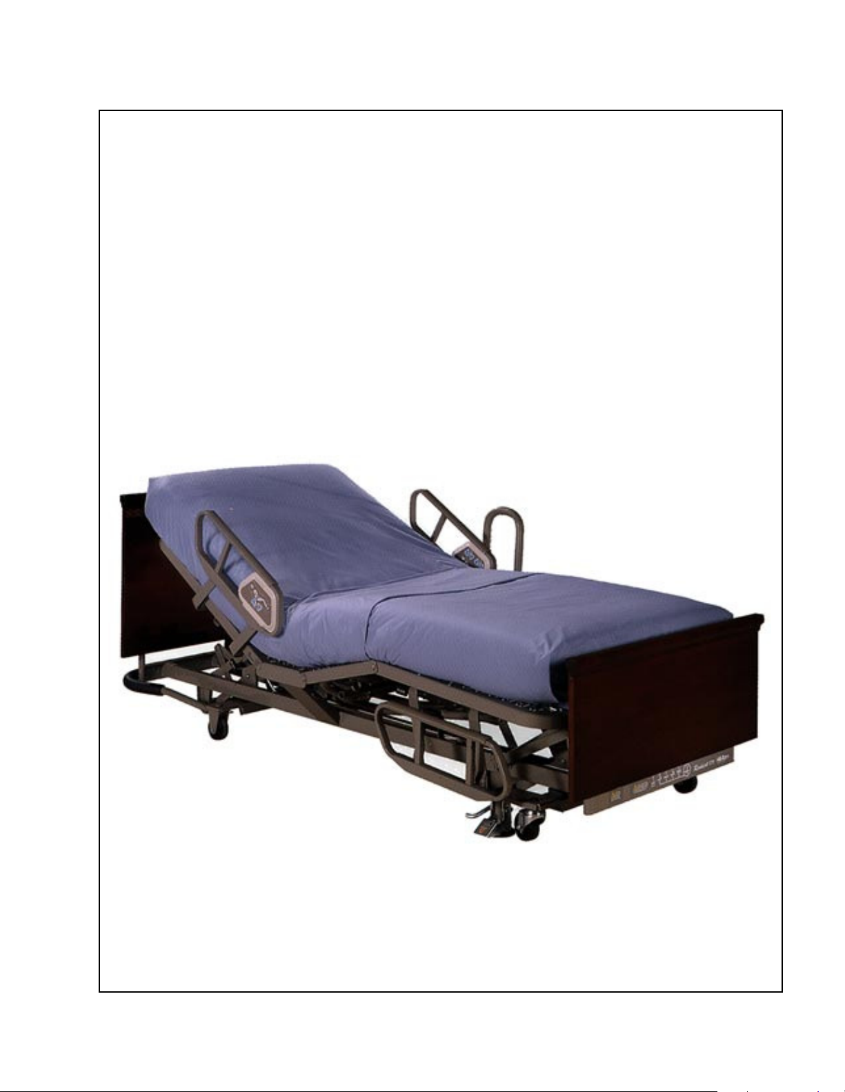
ResidentTM LTC Bed
From Hill-Rom
Product No. P870
For Parts Or Technical Assistance man136rc
USA 1-800-445-3720 Canada 1-800-267-2337

Revisions
ResidentTM LTC Bed
Service Manual
Revision Letter Pages Affected Date
Original Issue December, 1996
A All January, 1997
B All July, 1997
C All September, 1997
man136rc
ResidentTM LTC Bed Service Manual (man136rc) Page i

Revisions
COPYRIGHT 1997 HILL-ROM®, INC.
All rights reserved. No part of this text shall be reproduced or transmitted in
any form or by any means, electronic or mechanical, including photocopying,
recording, or by any information or retrieval system without written
permission from HILL-ROM COMPANY, INC. (Hill-Rom).
Fourth Edition
First Printing 1996
Printed in the USA
Comfortline® is a registered trademark of Hill-Rom Company, Inc.
Hill-Rom® is a registered trademark of Hill-Rom Company, Inc.
ResidentTM is a trademark of Hill-Rom Company, Inc.
ZoneAire® is a registered trademark of Hill-Rom Company, Inc.
Loctite® is a registered trademark of Loctite Company, Inc.
Teflon® is a registered trademark of E. I. du Pont, de Nemours & Co.
The information contained in this manual is subject to change without notice.
Hill-Rom makes no commitment to update or keep current, the information
contained in this manual.
The only product warranty intended by Hill-Rom is the express, written
warranty accompanying the bill of sale to the original purchaser. Hill-Rom
makes no other warranty, express or implied, and in particular, makes no
warranty of merchantability or fitness for a particular purpose.
Additional copies of this manual can be obtained from Hill-Rom.
Page ii ResidentTM LTC Bed Service Manual (man136rc)

Table of Contents
Chapter 1: Introduction
Purpose of this Manual . . . . . . . . . . . . . . . . . . . . . . . . . . . . . . . . . . . . . . . . . . . . . . 1 - 5
Who Should Use This Manual . . . . . . . . . . . . . . . . . . . . . . . . . . . . . . . . . . . . . . . . 1 - 5
Organization of Manual . . . . . . . . . . . . . . . . . . . . . . . . . . . . . . . . . . . . . . . . . . . . . 1 - 5
Chapter 1: Introduction. . . . . . . . . . . . . . . . . . . . . . . . . . . . . . . . . . . . . . . . 1 - 5
Chapter 2: Troubleshooting Procedures . . . . . . . . . . . . . . . . . . . . . . . . . . . 1 - 5
Chapter 3: Theory of Operation . . . . . . . . . . . . . . . . . . . . . . . . . . . . . . . . . 1 - 5
Chapter 4: Removal, Replacement, and Adjustment Procedures . . . . . . . . 1 - 6
Chapter 5: Parts List . . . . . . . . . . . . . . . . . . . . . . . . . . . . . . . . . . . . . . . . . . 1 - 6
Chapter 6: General Procedures . . . . . . . . . . . . . . . . . . . . . . . . . . . . . . . . . . 1 - 6
Chapter 7: Accessories . . . . . . . . . . . . . . . . . . . . . . . . . . . . . . . . . . . . . . . . 1 - 6
Typographical Conventions Used in this Manual. . . . . . . . . . . . . . . . . . . . . . . . . . 1 - 7
Introduction to the Resident
TM
LTC Manual Drive Bed . . . . . . . . . . . . . . . . . . . . . 1 - 8
Operating Precautions. . . . . . . . . . . . . . . . . . . . . . . . . . . . . . . . . . . . . . . . . . . . 1 - 8
Bed Positions . . . . . . . . . . . . . . . . . . . . . . . . . . . . . . . . . . . . . . . . . . . . . . . . . . 1 - 8
Resident
TM
LTC Manual Drive Bed Specifications . . . . . . . . . . . . . . . . . . . . . . . 1 - 10
Physical Description . . . . . . . . . . . . . . . . . . . . . . . . . . . . . . . . . . . . . . . . . . . . 1 - 10
Head Section Inclination. . . . . . . . . . . . . . . . . . . . . . . . . . . . . . . . . . . . . . 1 - 11
Head Angle Indicators . . . . . . . . . . . . . . . . . . . . . . . . . . . . . . . . . . . . 1 - 11
Knee Section Inclination. . . . . . . . . . . . . . . . . . . . . . . . . . . . . . . . . . . . . . 1 - 11
Hilow . . . . . . . . . . . . . . . . . . . . . . . . . . . . . . . . . . . . . . . . . . . . . . . . . . . . 1 - 11
Steering . . . . . . . . . . . . . . . . . . . . . . . . . . . . . . . . . . . . . . . . . . . . . . . . . . . 1 - 11
Brakes . . . . . . . . . . . . . . . . . . . . . . . . . . . . . . . . . . . . . . . . . . . . . . . . . . . . 1 - 12
Siderails . . . . . . . . . . . . . . . . . . . . . . . . . . . . . . . . . . . . . . . . . . . . . . . . . . 1 - 12
Bumper . . . . . . . . . . . . . . . . . . . . . . . . . . . . . . . . . . . . . . . . . . . . . . . . . . . 1 - 12
IV Rod Sockets . . . . . . . . . . . . . . . . . . . . . . . . . . . . . . . . . . . . . . . . . . . . . 1 - 12
Sleep Surface Support Frame . . . . . . . . . . . . . . . . . . . . . . . . . . . . . . . . . . 1 - 12
ResidentTM LTC Bed Service Manual (man136rc) Page iii

Table of Contents
Mattress Stop . . . . . . . . . . . . . . . . . . . . . . . . . . . . . . . . . . . . . . . . . . . . . . 1 - 13
Mattress Configurations . . . . . . . . . . . . . . . . . . . . . . . . . . . . . . . . . . . . . . 1 - 13
Head and Foot Panels . . . . . . . . . . . . . . . . . . . . . . . . . . . . . . . . . . . . . . . . 1 - 13
Drainage Bag Hooks. . . . . . . . . . . . . . . . . . . . . . . . . . . . . . . . . . . . . . . . . 1 - 13
Mechanical Description . . . . . . . . . . . . . . . . . . . . . . . . . . . . . . . . . . . . . . . . . 1 - 13
General Operation of the Resident
Siderail Operation . . . . . . . . . . . . . . . . . . . . . . . . . . . . . . . . . . . . . . . . . . . . . . 1 - 15
Raise the Siderail . . . . . . . . . . . . . . . . . . . . . . . . . . . . . . . . . . . . . . . . . . . 1 - 15
Lower the Siderail. . . . . . . . . . . . . . . . . . . . . . . . . . . . . . . . . . . . . . . . . . . 1 - 15
Bed Positions . . . . . . . . . . . . . . . . . . . . . . . . . . . . . . . . . . . . . . . . . . . . . . . . . 1 - 16
Hilow . . . . . . . . . . . . . . . . . . . . . . . . . . . . . . . . . . . . . . . . . . . . . . . . . . . . 1 - 16
Head Section . . . . . . . . . . . . . . . . . . . . . . . . . . . . . . . . . . . . . . . . . . . . . . . 1 - 16
Knee Section . . . . . . . . . . . . . . . . . . . . . . . . . . . . . . . . . . . . . . . . . . . . . . . 1 - 16
TM
LTC Manual Drive Bed . . . . . . . . . . . . . . . 1 - 15
Steering . . . . . . . . . . . . . . . . . . . . . . . . . . . . . . . . . . . . . . . . . . . . . . . . . . . . . . 1 - 16
Brakes . . . . . . . . . . . . . . . . . . . . . . . . . . . . . . . . . . . . . . . . . . . . . . . . . . . . . . . 1 - 17
Head and Foot Panels . . . . . . . . . . . . . . . . . . . . . . . . . . . . . . . . . . . . . . . . . . . 1 - 17
Introduction to the Resident
TM
LTC Electric Drive Bed . . . . . . . . . . . . . . . . . . . . 1 - 18
Operating Precautions. . . . . . . . . . . . . . . . . . . . . . . . . . . . . . . . . . . . . . . . . . . 1 - 18
Bed Positions . . . . . . . . . . . . . . . . . . . . . . . . . . . . . . . . . . . . . . . . . . . . . . . . . 1 - 18
Resident
TM
LTC Electric Drive Bed Specifications . . . . . . . . . . . . . . . . . . . . . . . 1 - 21
Physical Description . . . . . . . . . . . . . . . . . . . . . . . . . . . . . . . . . . . . . . . . . . . . 1 - 21
Head Section Inclination. . . . . . . . . . . . . . . . . . . . . . . . . . . . . . . . . . . . . . 1 - 21
Head Angle Indicators . . . . . . . . . . . . . . . . . . . . . . . . . . . . . . . . . . . . 1 - 22
Knee Section Inclination. . . . . . . . . . . . . . . . . . . . . . . . . . . . . . . . . . . . . . 1 - 22
Hilow . . . . . . . . . . . . . . . . . . . . . . . . . . . . . . . . . . . . . . . . . . . . . . . . . . . . 1 - 22
Automatic Contour . . . . . . . . . . . . . . . . . . . . . . . . . . . . . . . . . . . . . . . . . . 1 - 22
Steering . . . . . . . . . . . . . . . . . . . . . . . . . . . . . . . . . . . . . . . . . . . . . . . . . . . 1 - 22
Brakes . . . . . . . . . . . . . . . . . . . . . . . . . . . . . . . . . . . . . . . . . . . . . . . . . . . . 1 - 23
Siderails . . . . . . . . . . . . . . . . . . . . . . . . . . . . . . . . . . . . . . . . . . . . . . . . . . 1 - 23
Bumper . . . . . . . . . . . . . . . . . . . . . . . . . . . . . . . . . . . . . . . . . . . . . . . . . . . 1 - 23
IV Rod Sockets . . . . . . . . . . . . . . . . . . . . . . . . . . . . . . . . . . . . . . . . . . . . . 1 - 23
Page iv ResidentTM LTC Bed Service Manual (man136rc)

Table of Contents
Sleep Surface Support Frame . . . . . . . . . . . . . . . . . . . . . . . . . . . . . . . . . . 1 - 23
Mattress Stop . . . . . . . . . . . . . . . . . . . . . . . . . . . . . . . . . . . . . . . . . . . . . . 1 - 24
Mattress Configurations . . . . . . . . . . . . . . . . . . . . . . . . . . . . . . . . . . . . . . 1 - 24
Head and Foot Panels . . . . . . . . . . . . . . . . . . . . . . . . . . . . . . . . . . . . . . . . 1 - 24
Drainage Bag Hooks. . . . . . . . . . . . . . . . . . . . . . . . . . . . . . . . . . . . . . . . . 1 - 24
Electrical Description . . . . . . . . . . . . . . . . . . . . . . . . . . . . . . . . . . . . . . . . . . . 1 - 24
Handset Control . . . . . . . . . . . . . . . . . . . . . . . . . . . . . . . . . . . . . . . . . . . . 1 - 25
Siderail Resident Control Panel . . . . . . . . . . . . . . . . . . . . . . . . . . . . . . . . 1 - 25
Siderail Caregiver Control Panel . . . . . . . . . . . . . . . . . . . . . . . . . . . . . . . 1 - 25
Control Box Lockout . . . . . . . . . . . . . . . . . . . . . . . . . . . . . . . . . . . . . . . . 1 - 25
Motor Actuators . . . . . . . . . . . . . . . . . . . . . . . . . . . . . . . . . . . . . . . . . . . . 1 - 26
Hilow . . . . . . . . . . . . . . . . . . . . . . . . . . . . . . . . . . . . . . . . . . . . . . . . . 1 - 26
Head . . . . . . . . . . . . . . . . . . . . . . . . . . . . . . . . . . . . . . . . . . . . . . . . . . 1 - 26
Knee . . . . . . . . . . . . . . . . . . . . . . . . . . . . . . . . . . . . . . . . . . . . . . . . . . 1 - 26
UL Classification . . . . . . . . . . . . . . . . . . . . . . . . . . . . . . . . . . . . . . . . . . . . . . 1 - 27
General Operation of the Resident
TM
LTC Electric Drive Bed . . . . . . . . . . . . . . . 1 - 28
Siderail Operation . . . . . . . . . . . . . . . . . . . . . . . . . . . . . . . . . . . . . . . . . . . . . . 1 - 28
Raise the Siderail . . . . . . . . . . . . . . . . . . . . . . . . . . . . . . . . . . . . . . . . . . . 1 - 28
Lower the Siderail. . . . . . . . . . . . . . . . . . . . . . . . . . . . . . . . . . . . . . . . . . . 1 - 28
Bed Positions . . . . . . . . . . . . . . . . . . . . . . . . . . . . . . . . . . . . . . . . . . . . . . . . . 1 - 29
Hilow . . . . . . . . . . . . . . . . . . . . . . . . . . . . . . . . . . . . . . . . . . . . . . . . . . . . 1 - 29
Head Section . . . . . . . . . . . . . . . . . . . . . . . . . . . . . . . . . . . . . . . . . . . . . . . 1 - 29
Knee Section . . . . . . . . . . . . . . . . . . . . . . . . . . . . . . . . . . . . . . . . . . . . . . . 1 - 29
Automatic Contour . . . . . . . . . . . . . . . . . . . . . . . . . . . . . . . . . . . . . . . . . . 1 - 30
Steering . . . . . . . . . . . . . . . . . . . . . . . . . . . . . . . . . . . . . . . . . . . . . . . . . . . . . . 1 - 30
Brakes . . . . . . . . . . . . . . . . . . . . . . . . . . . . . . . . . . . . . . . . . . . . . . . . . . . . . . . 1 - 30
Mattress Stop . . . . . . . . . . . . . . . . . . . . . . . . . . . . . . . . . . . . . . . . . . . . . . . . . 1 - 31
Head and Foot Panels . . . . . . . . . . . . . . . . . . . . . . . . . . . . . . . . . . . . . . . . . . . 1 - 31
Model Identification . . . . . . . . . . . . . . . . . . . . . . . . . . . . . . . . . . . . . . . . . . . . . . . 1 - 31
Safety Tips . . . . . . . . . . . . . . . . . . . . . . . . . . . . . . . . . . . . . . . . . . . . . . . . . . . . . . 1 - 32
Warning and Caution Labels . . . . . . . . . . . . . . . . . . . . . . . . . . . . . . . . . . . . . . . . 1 - 36
ResidentTM LTC Bed Service Manual (man136rc) Page v

Table of Contents
Chapter 2: Troubleshooting Procedures
Getting Started . . . . . . . . . . . . . . . . . . . . . . . . . . . . . . . . . . . . . . . . . . . . . . . . . . . . 2 - 3
Troubleshooting the Resident
TM
LTC Manual Drive Bed. . . . . . . . . . . . . . . . . . . . 2 - 4
Initial Actions—Manual Drive Model . . . . . . . . . . . . . . . . . . . . . . . . . . . . . . . 2 - 4
Function Checks—Manual Drive Model . . . . . . . . . . . . . . . . . . . . . . . . . . . . . . . . 2 - 5
Final Actions—Manual Drive Model . . . . . . . . . . . . . . . . . . . . . . . . . . . . . . . . . . . 2 - 8
Troubleshooting the Resident
TM
LTC Electric Drive Bed. . . . . . . . . . . . . . . . . . . . 2 - 9
Initial Actions—Electric Drive Model . . . . . . . . . . . . . . . . . . . . . . . . . . . . . . . 2 - 9
Function Checks—Electric Drive Model . . . . . . . . . . . . . . . . . . . . . . . . . . . . . . . 2 - 10
Final Actions—Electric Drive Model. . . . . . . . . . . . . . . . . . . . . . . . . . . . . . . . . . 2 - 18
Reduced Braking Ability . . . . . . . . . . . . . . . . . . . . . . . . . . . . . . . . . . . . . . . . . . . 2 - 19
Individually Operated Brakes . . . . . . . . . . . . . . . . . . . . . . . . . . . . . . . . . . . . . 2 - 19
Siderail Mechanical Malfunction . . . . . . . . . . . . . . . . . . . . . . . . . . . . . . . . . . . . . 2 - 20
Loose, Bent, or Missing Hardware . . . . . . . . . . . . . . . . . . . . . . . . . . . . . . . . . . . . 2 - 22
Manual Hilow Function Does Not Raise or Lower Correctly . . . . . . . . . . . . . . . 2 - 23
Manual Head Section Does Not Raise or Lower Correctly . . . . . . . . . . . . . . . . . 2 - 25
Manual Knee Section Does Not Raise or Lower Correctly . . . . . . . . . . . . . . . . . 2 - 27
Electric Hilow Does Not Raise or Lower Correctly . . . . . . . . . . . . . . . . . . . . . . . 2 - 29
Electric Head Section Does Not Raise Or Lower Correctly. . . . . . . . . . . . . . . . . 2 - 32
Electric Knee Section Does Not Raise Or Lower Correctly. . . . . . . . . . . . . . . . . 2 - 35
Automatic Contour Does Not Function Correctly . . . . . . . . . . . . . . . . . . . . . . . . 2 - 38
Control Lockout Does Not Function Correctly . . . . . . . . . . . . . . . . . . . . . . . . . . 2 - 41
None Of The Electrical Functions Operate. . . . . . . . . . . . . . . . . . . . . . . . . . . . . . 2 - 44
Siderail Control/Handset Control Does Not Operate Correctly . . . . . . . . . . . . . . 2 - 46
Chapter 3: Theory of Operation
Electrical System Block Diagram. . . . . . . . . . . . . . . . . . . . . . . . . . . . . . . . . . . . . . 3 - 3
Siderail Control Schematic . . . . . . . . . . . . . . . . . . . . . . . . . . . . . . . . . . . . . . . . . . . 3 - 4
Siderail Control Circuit Boards . . . . . . . . . . . . . . . . . . . . . . . . . . . . . . . . . . . . . . . 3 - 5
Electrical Theory of Operation . . . . . . . . . . . . . . . . . . . . . . . . . . . . . . . . . . . . . . . . 3 - 6
Motor Actuators . . . . . . . . . . . . . . . . . . . . . . . . . . . . . . . . . . . . . . . . . . . . . . . . 3 - 8
Hilow . . . . . . . . . . . . . . . . . . . . . . . . . . . . . . . . . . . . . . . . . . . . . . . . . . . . . 3 - 8
Page vi ResidentTM LTC Bed Service Manual (man136rc)

Table of Contents
Head . . . . . . . . . . . . . . . . . . . . . . . . . . . . . . . . . . . . . . . . . . . . . . . . . . . . . . 3 - 8
Knee . . . . . . . . . . . . . . . . . . . . . . . . . . . . . . . . . . . . . . . . . . . . . . . . . . . . . . 3 - 8
Handset Control . . . . . . . . . . . . . . . . . . . . . . . . . . . . . . . . . . . . . . . . . . . . . . . . 3 - 8
Optional Resident and Caregiver Siderail Controls . . . . . . . . . . . . . . . . . . . . . 3 - 9
Resident Control Panel . . . . . . . . . . . . . . . . . . . . . . . . . . . . . . . . . . . . . . . . 3 - 9
Caregiver Control Panel . . . . . . . . . . . . . . . . . . . . . . . . . . . . . . . . . . . . . . . 3 - 9
Control Lockout Box . . . . . . . . . . . . . . . . . . . . . . . . . . . . . . . . . . . . . . . . . . . . 3 - 9
Chapter 4: Removal, Replacement, and Adjustment Procedures
Manual Hilow Drive Assembly . . . . . . . . . . . . . . . . . . . . . . . . . . . . . . . . . . . . . . . 4 - 5
Removal . . . . . . . . . . . . . . . . . . . . . . . . . . . . . . . . . . . . . . . . . . . . . . . . . . . . . . 4 - 5
Replacement . . . . . . . . . . . . . . . . . . . . . . . . . . . . . . . . . . . . . . . . . . . . . . . . . . . 4 - 7
Manual Head Drive Assembly . . . . . . . . . . . . . . . . . . . . . . . . . . . . . . . . . . . . . . . . 4 - 9
Removal . . . . . . . . . . . . . . . . . . . . . . . . . . . . . . . . . . . . . . . . . . . . . . . . . . . . . . 4 - 9
Replacement . . . . . . . . . . . . . . . . . . . . . . . . . . . . . . . . . . . . . . . . . . . . . . . . . . 4 - 11
Manual Knee Drive Assembly . . . . . . . . . . . . . . . . . . . . . . . . . . . . . . . . . . . . . . . 4 - 13
Removal . . . . . . . . . . . . . . . . . . . . . . . . . . . . . . . . . . . . . . . . . . . . . . . . . . . . . 4 - 13
Replacement . . . . . . . . . . . . . . . . . . . . . . . . . . . . . . . . . . . . . . . . . . . . . . . . . . 4 - 14
Hilow Motor Actuator . . . . . . . . . . . . . . . . . . . . . . . . . . . . . . . . . . . . . . . . . . . . . 4 - 16
Removal . . . . . . . . . . . . . . . . . . . . . . . . . . . . . . . . . . . . . . . . . . . . . . . . . . . . . 4 - 16
Replacement . . . . . . . . . . . . . . . . . . . . . . . . . . . . . . . . . . . . . . . . . . . . . . . . . . 4 - 17
Head Section Motor Actuator . . . . . . . . . . . . . . . . . . . . . . . . . . . . . . . . . . . . . . . . 4 - 18
Removal . . . . . . . . . . . . . . . . . . . . . . . . . . . . . . . . . . . . . . . . . . . . . . . . . . . . . 4 - 18
Replacement . . . . . . . . . . . . . . . . . . . . . . . . . . . . . . . . . . . . . . . . . . . . . . . . . . 4 - 19
Knee Section Motor Actuator . . . . . . . . . . . . . . . . . . . . . . . . . . . . . . . . . . . . . . . . 4 - 20
Removal . . . . . . . . . . . . . . . . . . . . . . . . . . . . . . . . . . . . . . . . . . . . . . . . . . . . . 4 - 20
Replacement . . . . . . . . . . . . . . . . . . . . . . . . . . . . . . . . . . . . . . . . . . . . . . . . . . 4 - 21
Automatic Contour Module . . . . . . . . . . . . . . . . . . . . . . . . . . . . . . . . . . . . . . . . . 4 - 22
Removal . . . . . . . . . . . . . . . . . . . . . . . . . . . . . . . . . . . . . . . . . . . . . . . . . . . . . 4 - 22
Replacement . . . . . . . . . . . . . . . . . . . . . . . . . . . . . . . . . . . . . . . . . . . . . . . . . . 4 - 23
Adjustment . . . . . . . . . . . . . . . . . . . . . . . . . . . . . . . . . . . . . . . . . . . . . . . . . . . 4 - 25
Optional Siderail Control Panels . . . . . . . . . . . . . . . . . . . . . . . . . . . . . . . . . . . . . 4 - 27
ResidentTM LTC Bed Service Manual (man136rc) Page vii

Table of Contents
Removal . . . . . . . . . . . . . . . . . . . . . . . . . . . . . . . . . . . . . . . . . . . . . . . . . . . . . 4 - 27
Replacement . . . . . . . . . . . . . . . . . . . . . . . . . . . . . . . . . . . . . . . . . . . . . . . . . . 4 - 30
Handset Control . . . . . . . . . . . . . . . . . . . . . . . . . . . . . . . . . . . . . . . . . . . . . . . . . . 4 - 31
Removal . . . . . . . . . . . . . . . . . . . . . . . . . . . . . . . . . . . . . . . . . . . . . . . . . . . . . 4 - 31
Replacement . . . . . . . . . . . . . . . . . . . . . . . . . . . . . . . . . . . . . . . . . . . . . . . . . . 4 - 31
Control Lockout Box . . . . . . . . . . . . . . . . . . . . . . . . . . . . . . . . . . . . . . . . . . . . . . 4 - 33
Removal . . . . . . . . . . . . . . . . . . . . . . . . . . . . . . . . . . . . . . . . . . . . . . . . . . . . . 4 - 33
Replacement . . . . . . . . . . . . . . . . . . . . . . . . . . . . . . . . . . . . . . . . . . . . . . . . . . 4 - 34
Control Box. . . . . . . . . . . . . . . . . . . . . . . . . . . . . . . . . . . . . . . . . . . . . . . . . . . . . . 4 - 35
Removal . . . . . . . . . . . . . . . . . . . . . . . . . . . . . . . . . . . . . . . . . . . . . . . . . . . . . 4 - 35
Replacement . . . . . . . . . . . . . . . . . . . . . . . . . . . . . . . . . . . . . . . . . . . . . . . . . . 4 - 36
Siderails . . . . . . . . . . . . . . . . . . . . . . . . . . . . . . . . . . . . . . . . . . . . . . . . . . . . . . . . 4 - 37
Removal . . . . . . . . . . . . . . . . . . . . . . . . . . . . . . . . . . . . . . . . . . . . . . . . . . . . . 4 - 37
Replacement . . . . . . . . . . . . . . . . . . . . . . . . . . . . . . . . . . . . . . . . . . . . . . . . . . 4 - 38
Siderail Latch . . . . . . . . . . . . . . . . . . . . . . . . . . . . . . . . . . . . . . . . . . . . . . . . . . . . 4 - 40
Adjustment . . . . . . . . . . . . . . . . . . . . . . . . . . . . . . . . . . . . . . . . . . . . . . . . . . . 4 - 40
Sleep Surface Frame Assembly . . . . . . . . . . . . . . . . . . . . . . . . . . . . . . . . . . . . . . 4 - 41
Removal . . . . . . . . . . . . . . . . . . . . . . . . . . . . . . . . . . . . . . . . . . . . . . . . . . . . . 4 - 41
Replacement . . . . . . . . . . . . . . . . . . . . . . . . . . . . . . . . . . . . . . . . . . . . . . . . . . 4 - 43
Fixed Casters. . . . . . . . . . . . . . . . . . . . . . . . . . . . . . . . . . . . . . . . . . . . . . . . . . . . . 4 - 44
Removal . . . . . . . . . . . . . . . . . . . . . . . . . . . . . . . . . . . . . . . . . . . . . . . . . . . . . 4 - 44
Replacement . . . . . . . . . . . . . . . . . . . . . . . . . . . . . . . . . . . . . . . . . . . . . . . . . . 4 - 45
Fixed Casters (model B) . . . . . . . . . . . . . . . . . . . . . . . . . . . . . . . . . . . . . . . . . . . . 4 - 46
Removal . . . . . . . . . . . . . . . . . . . . . . . . . . . . . . . . . . . . . . . . . . . . . . . . . . . . . 4 - 46
Replacement . . . . . . . . . . . . . . . . . . . . . . . . . . . . . . . . . . . . . . . . . . . . . . . . . . 4 - 47
Swivel Casters. . . . . . . . . . . . . . . . . . . . . . . . . . . . . . . . . . . . . . . . . . . . . . . . . . . . 4 - 48
Removal . . . . . . . . . . . . . . . . . . . . . . . . . . . . . . . . . . . . . . . . . . . . . . . . . . . . . 4 - 48
Replacement . . . . . . . . . . . . . . . . . . . . . . . . . . . . . . . . . . . . . . . . . . . . . . . . . . 4 - 49
Individually Operated Brakes . . . . . . . . . . . . . . . . . . . . . . . . . . . . . . . . . . . . . . . . 4 - 50
Removal . . . . . . . . . . . . . . . . . . . . . . . . . . . . . . . . . . . . . . . . . . . . . . . . . . . . . 4 - 50
Replacement . . . . . . . . . . . . . . . . . . . . . . . . . . . . . . . . . . . . . . . . . . . . . . . . . . 4 - 51
Page viii ResidentTM LTC Bed Service Manual (man136rc)

Table of Contents
Bumper Assembly. . . . . . . . . . . . . . . . . . . . . . . . . . . . . . . . . . . . . . . . . . . . . . . . . 4 - 52
Removal . . . . . . . . . . . . . . . . . . . . . . . . . . . . . . . . . . . . . . . . . . . . . . . . . . . . . 4 - 52
Replacement . . . . . . . . . . . . . . . . . . . . . . . . . . . . . . . . . . . . . . . . . . . . . . . . . . 4 - 52
Bumper Assembly (model B) . . . . . . . . . . . . . . . . . . . . . . . . . . . . . . . . . . . . . . . . 4 - 53
Removal . . . . . . . . . . . . . . . . . . . . . . . . . . . . . . . . . . . . . . . . . . . . . . . . . . . . . 4 - 53
Replacement . . . . . . . . . . . . . . . . . . . . . . . . . . . . . . . . . . . . . . . . . . . . . . . . . . 4 - 53
Chapter 5: Parts List
Warranty . . . . . . . . . . . . . . . . . . . . . . . . . . . . . . . . . . . . . . . . . . . . . . . . . . . . . . . . . 5 - 3
Service Parts Ordering . . . . . . . . . . . . . . . . . . . . . . . . . . . . . . . . . . . . . . . . . . . . . . 5 - 5
Exchange Policy . . . . . . . . . . . . . . . . . . . . . . . . . . . . . . . . . . . . . . . . . . . . . . . . . . . 5 - 7
In-Warranty Exchanges . . . . . . . . . . . . . . . . . . . . . . . . . . . . . . . . . . . . . . . . . . 5 - 7
Out-of-Warranty Exchanges . . . . . . . . . . . . . . . . . . . . . . . . . . . . . . . . . . . . . . . 5 - 7
Recommended Spare Parts . . . . . . . . . . . . . . . . . . . . . . . . . . . . . . . . . . . . . . . . . . . 5 - 8
Sleep Surface Frame Assembly . . . . . . . . . . . . . . . . . . . . . . . . . . . . . . . . . . . . . . 5 - 10
Lower Frame Assembly . . . . . . . . . . . . . . . . . . . . . . . . . . . . . . . . . . . . . . . . . . . . 5 - 12
Caster Frame Assemblies—"A" Version . . . . . . . . . . . . . . . . . . . . . . . . . . . . . . . 5 - 14
Caster Frame Assemblies—"B" Version . . . . . . . . . . . . . . . . . . . . . . . . . . . . . . . 5 - 16
Surface Assemblies. . . . . . . . . . . . . . . . . . . . . . . . . . . . . . . . . . . . . . . . . . . . . . . . 5 - 18
Electrical and Label Assemblies. . . . . . . . . . . . . . . . . . . . . . . . . . . . . . . . . . . . . . 5 - 20
Manual Drive Module and Label Assemblies . . . . . . . . . . . . . . . . . . . . . . . . . . . 5 - 22
Siderail Assemblies. . . . . . . . . . . . . . . . . . . . . . . . . . . . . . . . . . . . . . . . . . . . . . . . 5 - 24
Head End Siderail Assemblies—With Control . . . . . . . . . . . . . . . . . . . . . . . . . . 5 - 26
Siderail Assemblies—Without Control . . . . . . . . . . . . . . . . . . . . . . . . . . . . . . . . 5 - 30
Standard Head and Foot Panel Assemblies—P4069 . . . . . . . . . . . . . . . . . . . . . . 5 - 32
Standard Foot Panel Assembly (manual drive)—P4069 . . . . . . . . . . . . . . . . . . . 5 - 33
Hearthside Head and Foot Panel Assemblies—P4071 . . . . . . . . . . . . . . . . . . . . . 5 - 34
Heirloom Head and Foot Panel Assemblies—P4072 . . . . . . . . . . . . . . . . . . . . . . 5 - 35
Post Style Head and Foot Panel Assemblies—P4073 . . . . . . . . . . . . . . . . . . . . . 5 - 36
Dentil Head and Foot Panel Assemblies—P4074 . . . . . . . . . . . . . . . . . . . . . . . . 5 - 37
Chapter 6: General Procedures
Cleaning and Care. . . . . . . . . . . . . . . . . . . . . . . . . . . . . . . . . . . . . . . . . . . . . . . . . . 6 - 3
ResidentTM LTC Bed Service Manual (man136rc) Page ix

Table of Contents
General Cleaning . . . . . . . . . . . . . . . . . . . . . . . . . . . . . . . . . . . . . . . . . . . . . . . 6 - 3
Steam Cleaning . . . . . . . . . . . . . . . . . . . . . . . . . . . . . . . . . . . . . . . . . . . . . . . . . 6 - 3
Hard to Clean Spots . . . . . . . . . . . . . . . . . . . . . . . . . . . . . . . . . . . . . . . . . . . . . 6 - 3
Disinfection. . . . . . . . . . . . . . . . . . . . . . . . . . . . . . . . . . . . . . . . . . . . . . . . . . . . 6 - 3
Mattress Care . . . . . . . . . . . . . . . . . . . . . . . . . . . . . . . . . . . . . . . . . . . . . . . . . . 6 - 3
Care of Wood Head and Foot Panels . . . . . . . . . . . . . . . . . . . . . . . . . . . . . . . . 6 - 4
Lubrication Requirements. . . . . . . . . . . . . . . . . . . . . . . . . . . . . . . . . . . . . . . . . . . . 6 - 5
Preventive Maintenance . . . . . . . . . . . . . . . . . . . . . . . . . . . . . . . . . . . . . . . . . . . . . 6 - 5
Preventive Maintenance Schedule—Manual Drive Model . . . . . . . . . . . . . . . 6 - 7
Preventive Maintenance Checklist—Manual Drive Model . . . . . . . . . . . . . . . 6 - 8
Preventive Maintenance Schedule—Electric Drive Model . . . . . . . . . . . . . . . 6 - 9
Preventive Maintenance Checklist—Electric Drive Model . . . . . . . . . . . . . . 6 - 10
Tool and Supply Requirements. . . . . . . . . . . . . . . . . . . . . . . . . . . . . . . . . . . . . . . 6 - 11
Leakage Current Test for Electric Drive Model . . . . . . . . . . . . . . . . . . . . . . . . . . 6 - 12
Chapter 7: Accessories
Accessories . . . . . . . . . . . . . . . . . . . . . . . . . . . . . . . . . . . . . . . . . . . . . . . . . . . . . . . 7 - 3
IV Rod (P2217). . . . . . . . . . . . . . . . . . . . . . . . . . . . . . . . . . . . . . . . . . . . . . . . . . . . 7 - 4
Installation . . . . . . . . . . . . . . . . . . . . . . . . . . . . . . . . . . . . . . . . . . . . . . . . . . . . 7 - 4
Adjusting. . . . . . . . . . . . . . . . . . . . . . . . . . . . . . . . . . . . . . . . . . . . . . . . . . . . . . 7 - 4
Removal . . . . . . . . . . . . . . . . . . . . . . . . . . . . . . . . . . . . . . . . . . . . . . . . . . . . . . 7 - 4
Trapeze Support (P846) . . . . . . . . . . . . . . . . . . . . . . . . . . . . . . . . . . . . . . . . . . . . . 7 - 5
Installation . . . . . . . . . . . . . . . . . . . . . . . . . . . . . . . . . . . . . . . . . . . . . . . . . . . . 7 - 5
Oxygen Tank Holder (P27601). . . . . . . . . . . . . . . . . . . . . . . . . . . . . . . . . . . . . . . . 7 - 6
Installation . . . . . . . . . . . . . . . . . . . . . . . . . . . . . . . . . . . . . . . . . . . . . . . . . . . . 7 - 6
Three-quarter Length Siderails (P866) . . . . . . . . . . . . . . . . . . . . . . . . . . . . . . . . . . 7 - 7
Installation . . . . . . . . . . . . . . . . . . . . . . . . . . . . . . . . . . . . . . . . . . . . . . . . . . . . 7 - 7
Full Length Siderails (P867). . . . . . . . . . . . . . . . . . . . . . . . . . . . . . . . . . . . . . . . . . 7 - 9
Installation . . . . . . . . . . . . . . . . . . . . . . . . . . . . . . . . . . . . . . . . . . . . . . . . . . . . 7 - 9
Standard Head and Foot Panels (P4069) . . . . . . . . . . . . . . . . . . . . . . . . . . . . . . . 7 - 11
Installation . . . . . . . . . . . . . . . . . . . . . . . . . . . . . . . . . . . . . . . . . . . . . . . . . . . 7 - 11
Hearthside Head and Foot Panels (P4071) . . . . . . . . . . . . . . . . . . . . . . . . . . . . . . 7 - 12
Page x ResidentTM LTC Bed Service Manual (man136rc)

Table of Contents
Installation . . . . . . . . . . . . . . . . . . . . . . . . . . . . . . . . . . . . . . . . . . . . . . . . . . . 7 - 12
Heirloom Head and Foot Panels (P4072) . . . . . . . . . . . . . . . . . . . . . . . . . . . . . . . 7 - 13
Installation . . . . . . . . . . . . . . . . . . . . . . . . . . . . . . . . . . . . . . . . . . . . . . . . . . . 7 - 13
Post Style Head and Foot Panels (P4073) . . . . . . . . . . . . . . . . . . . . . . . . . . . . . . 7 - 14
Installation . . . . . . . . . . . . . . . . . . . . . . . . . . . . . . . . . . . . . . . . . . . . . . . . . . . 7 - 14
Dentil Head and Foot Panels (P4074). . . . . . . . . . . . . . . . . . . . . . . . . . . . . . . . . . 7 - 15
Installation . . . . . . . . . . . . . . . . . . . . . . . . . . . . . . . . . . . . . . . . . . . . . . . . . . . 7 - 15
Comfortline® Mattress (P1433) . . . . . . . . . . . . . . . . . . . . . . . . . . . . . . . . . . . . . . 7 - 16
Installation . . . . . . . . . . . . . . . . . . . . . . . . . . . . . . . . . . . . . . . . . . . . . . . . . . . 7 - 16
Ambulatory Assist Rail (P441A) . . . . . . . . . . . . . . . . . . . . . . . . . . . . . . . . . . . . . 7 - 16
Auxiliary Power Supply (P442) . . . . . . . . . . . . . . . . . . . . . . . . . . . . . . . . . . . . . . 7 - 17
Trendelenburg/Reverse Trendelenburg Adapter (P865). . . . . . . . . . . . . . . . . . . . 7 - 17
ResidentTM LTC Bed Electric Upgrade Kit (P9951) . . . . . . . . . . . . . . . . . . . . . . . 7 - 18
ResidentTM LTC Bed Service Manual (man136rc) Page xi

Table of Contents
NOTES:
Page xii ResidentTM LTC Bed Service Manual (man136rc)

Chapter 1
Introduction
Chapter Contents
Purpose of this Manual . . . . . . . . . . . . . . . . . . . . . . . . . . . . . . . . . . . . . . . . . . . . . . 1 - 5
Who Should Use This Manual . . . . . . . . . . . . . . . . . . . . . . . . . . . . . . . . . . . . . . . . 1 - 5
Organization of Manual . . . . . . . . . . . . . . . . . . . . . . . . . . . . . . . . . . . . . . . . . . . . . 1 - 5
Chapter 1: Introduction. . . . . . . . . . . . . . . . . . . . . . . . . . . . . . . . . . . . . . . . 1 - 5
Chapter 2: Troubleshooting Procedures . . . . . . . . . . . . . . . . . . . . . . . . . . . 1 - 5
Chapter 3: Theory of Operation . . . . . . . . . . . . . . . . . . . . . . . . . . . . . . . . . 1 - 5
Chapter 4: Removal, Replacement, and Adjustment Procedures . . . . . . . . 1 - 6
1
Chapter 5: Parts List . . . . . . . . . . . . . . . . . . . . . . . . . . . . . . . . . . . . . . . . . . 1 - 6
Chapter 6: General Procedures . . . . . . . . . . . . . . . . . . . . . . . . . . . . . . . . . . 1 - 6
Chapter 7: Accessories . . . . . . . . . . . . . . . . . . . . . . . . . . . . . . . . . . . . . . . . 1 - 6
Typographical Conventions Used in this Manual. . . . . . . . . . . . . . . . . . . . . . . . . . 1 - 7
Introduction to the Resident
Operating Precautions. . . . . . . . . . . . . . . . . . . . . . . . . . . . . . . . . . . . . . . . . . . . 1 - 8
Bed Positions . . . . . . . . . . . . . . . . . . . . . . . . . . . . . . . . . . . . . . . . . . . . . . . . . . 1 - 8
Resident
TM
LTC Manual Drive Bed Specifications . . . . . . . . . . . . . . . . . . . . . . . . 1 - 10
Physical Description . . . . . . . . . . . . . . . . . . . . . . . . . . . . . . . . . . . . . . . . . . . . 1 - 10
Head Section Inclination. . . . . . . . . . . . . . . . . . . . . . . . . . . . . . . . . . . . . . 1 - 11
Head Angle Indicators . . . . . . . . . . . . . . . . . . . . . . . . . . . . . . . . . . . . 1 - 11
Knee Section Inclination. . . . . . . . . . . . . . . . . . . . . . . . . . . . . . . . . . . . . . 1 - 11
Hilow . . . . . . . . . . . . . . . . . . . . . . . . . . . . . . . . . . . . . . . . . . . . . . . . . . . . 1 - 11
Steering . . . . . . . . . . . . . . . . . . . . . . . . . . . . . . . . . . . . . . . . . . . . . . . . . . . 1 - 11
Brakes . . . . . . . . . . . . . . . . . . . . . . . . . . . . . . . . . . . . . . . . . . . . . . . . . . . . 1 - 12
TM
LTC Manual Drive Bed. . . . . . . . . . . . . . . . . . . . . . 1 - 8
Siderails . . . . . . . . . . . . . . . . . . . . . . . . . . . . . . . . . . . . . . . . . . . . . . . . . . 1 - 12
ResidentTM LTC Bed Service Manual (man136rc) Page 1 - 1

1
Chapter 1: Introduction
Bumper . . . . . . . . . . . . . . . . . . . . . . . . . . . . . . . . . . . . . . . . . . . . . . . . . . . 1 - 12
IV Rod Sockets . . . . . . . . . . . . . . . . . . . . . . . . . . . . . . . . . . . . . . . . . . . . . 1 - 12
Sleep Surface Support Frame . . . . . . . . . . . . . . . . . . . . . . . . . . . . . . . . . . 1 - 12
Mattress Stop . . . . . . . . . . . . . . . . . . . . . . . . . . . . . . . . . . . . . . . . . . . . . . 1 - 13
Mattress Configurations . . . . . . . . . . . . . . . . . . . . . . . . . . . . . . . . . . . . . . 1 - 13
Head and Foot Panels . . . . . . . . . . . . . . . . . . . . . . . . . . . . . . . . . . . . . . . . 1 - 13
Drainage Bag Hooks. . . . . . . . . . . . . . . . . . . . . . . . . . . . . . . . . . . . . . . . . 1 - 13
Mechanical Description . . . . . . . . . . . . . . . . . . . . . . . . . . . . . . . . . . . . . . . . . 1 - 13
General Operation of the ResidentTM LTC Manual Drive Bed . . . . . . . . . . . . . . . 1 - 15
Siderail Operation . . . . . . . . . . . . . . . . . . . . . . . . . . . . . . . . . . . . . . . . . . . . . . 1 - 15
Raise the Siderail . . . . . . . . . . . . . . . . . . . . . . . . . . . . . . . . . . . . . . . . . . . 1 - 15
Lower the Siderail. . . . . . . . . . . . . . . . . . . . . . . . . . . . . . . . . . . . . . . . . . . 1 - 15
Bed Positions . . . . . . . . . . . . . . . . . . . . . . . . . . . . . . . . . . . . . . . . . . . . . . . . . 1 - 16
Hilow . . . . . . . . . . . . . . . . . . . . . . . . . . . . . . . . . . . . . . . . . . . . . . . . . . . . 1 - 16
Head Section . . . . . . . . . . . . . . . . . . . . . . . . . . . . . . . . . . . . . . . . . . . . . . . 1 - 16
Knee Section . . . . . . . . . . . . . . . . . . . . . . . . . . . . . . . . . . . . . . . . . . . . . . . 1 - 16
Steering . . . . . . . . . . . . . . . . . . . . . . . . . . . . . . . . . . . . . . . . . . . . . . . . . . . . . . 1 - 16
Brakes . . . . . . . . . . . . . . . . . . . . . . . . . . . . . . . . . . . . . . . . . . . . . . . . . . . . . . . 1 - 17
Head and Foot Panels . . . . . . . . . . . . . . . . . . . . . . . . . . . . . . . . . . . . . . . . . . . 1 - 17
Introduction to the Resident
Operating Precautions. . . . . . . . . . . . . . . . . . . . . . . . . . . . . . . . . . . . . . . . . . . 1 - 18
Bed Positions . . . . . . . . . . . . . . . . . . . . . . . . . . . . . . . . . . . . . . . . . . . . . . . . . 1 - 18
ResidentTM LTC Electric Drive Bed Specifications. . . . . . . . . . . . . . . . . . . . . . . . 1 - 21
Physical Description . . . . . . . . . . . . . . . . . . . . . . . . . . . . . . . . . . . . . . . . . . . . 1 - 21
Head Section Inclination. . . . . . . . . . . . . . . . . . . . . . . . . . . . . . . . . . . . . . 1 - 21
Head Angle Indicators . . . . . . . . . . . . . . . . . . . . . . . . . . . . . . . . . . . . 1 - 22
Knee Section Inclination. . . . . . . . . . . . . . . . . . . . . . . . . . . . . . . . . . . . . . 1 - 22
Hilow . . . . . . . . . . . . . . . . . . . . . . . . . . . . . . . . . . . . . . . . . . . . . . . . . . . . 1 - 22
TM
LTC Electric Drive Bed . . . . . . . . . . . . . . . . . . . . 1 - 18
Automatic Contour . . . . . . . . . . . . . . . . . . . . . . . . . . . . . . . . . . . . . . . . . . 1 - 22
Steering . . . . . . . . . . . . . . . . . . . . . . . . . . . . . . . . . . . . . . . . . . . . . . . . . . . 1 - 22
Brakes . . . . . . . . . . . . . . . . . . . . . . . . . . . . . . . . . . . . . . . . . . . . . . . . . . . . 1 - 23
Page 1 - 2 ResidentTM LTC Bed Service Manual (man136rc)

Chapter 1: Introduction
Siderails . . . . . . . . . . . . . . . . . . . . . . . . . . . . . . . . . . . . . . . . . . . . . . . . . . 1 - 23
Bumper . . . . . . . . . . . . . . . . . . . . . . . . . . . . . . . . . . . . . . . . . . . . . . . . . . . 1 - 23
IV Rod Sockets . . . . . . . . . . . . . . . . . . . . . . . . . . . . . . . . . . . . . . . . . . . . . 1 - 23
Sleep Surface Support Frame . . . . . . . . . . . . . . . . . . . . . . . . . . . . . . . . . . 1 - 23
Mattress Stop . . . . . . . . . . . . . . . . . . . . . . . . . . . . . . . . . . . . . . . . . . . . . . 1 - 24
Mattress Configurations . . . . . . . . . . . . . . . . . . . . . . . . . . . . . . . . . . . . . . 1 - 24
Head and Foot Panels . . . . . . . . . . . . . . . . . . . . . . . . . . . . . . . . . . . . . . . . 1 - 24
Drainage Bag Hooks. . . . . . . . . . . . . . . . . . . . . . . . . . . . . . . . . . . . . . . . . 1 - 24
Electrical Description . . . . . . . . . . . . . . . . . . . . . . . . . . . . . . . . . . . . . . . . . . . 1 - 24
Handset Control . . . . . . . . . . . . . . . . . . . . . . . . . . . . . . . . . . . . . . . . . . . . 1 - 25
Siderail Resident Control Panel . . . . . . . . . . . . . . . . . . . . . . . . . . . . . . . . 1 - 25
Siderail Caregiver Control Panel . . . . . . . . . . . . . . . . . . . . . . . . . . . . . . . 1 - 25
Control Box Lockout . . . . . . . . . . . . . . . . . . . . . . . . . . . . . . . . . . . . . . . . 1 - 25
1
Motor Actuators . . . . . . . . . . . . . . . . . . . . . . . . . . . . . . . . . . . . . . . . . . . . 1 - 26
Hilow . . . . . . . . . . . . . . . . . . . . . . . . . . . . . . . . . . . . . . . . . . . . . . . . . 1 - 26
Head . . . . . . . . . . . . . . . . . . . . . . . . . . . . . . . . . . . . . . . . . . . . . . . . . . 1 - 26
Knee . . . . . . . . . . . . . . . . . . . . . . . . . . . . . . . . . . . . . . . . . . . . . . . . . . 1 - 26
UL Classification . . . . . . . . . . . . . . . . . . . . . . . . . . . . . . . . . . . . . . . . . . . . . . 1 - 27
General Operation of the Resident
Siderail Operation . . . . . . . . . . . . . . . . . . . . . . . . . . . . . . . . . . . . . . . . . . . . . . 1 - 28
Raise the Siderail . . . . . . . . . . . . . . . . . . . . . . . . . . . . . . . . . . . . . . . . . . . 1 - 28
Lower the Siderail. . . . . . . . . . . . . . . . . . . . . . . . . . . . . . . . . . . . . . . . . . . 1 - 28
Bed Positions . . . . . . . . . . . . . . . . . . . . . . . . . . . . . . . . . . . . . . . . . . . . . . . . . 1 - 29
Hilow . . . . . . . . . . . . . . . . . . . . . . . . . . . . . . . . . . . . . . . . . . . . . . . . . . . . 1 - 29
Head Section . . . . . . . . . . . . . . . . . . . . . . . . . . . . . . . . . . . . . . . . . . . . . . . 1 - 29
Knee Section . . . . . . . . . . . . . . . . . . . . . . . . . . . . . . . . . . . . . . . . . . . . . . . 1 - 29
Automatic Contour . . . . . . . . . . . . . . . . . . . . . . . . . . . . . . . . . . . . . . . . . . 1 - 30
Steering . . . . . . . . . . . . . . . . . . . . . . . . . . . . . . . . . . . . . . . . . . . . . . . . . . . . . . 1 - 30
TM
LTC Electric Drive Bed . . . . . . . . . . . . . . . 1 - 28
Brakes . . . . . . . . . . . . . . . . . . . . . . . . . . . . . . . . . . . . . . . . . . . . . . . . . . . . . . . 1 - 30
Mattress Stop . . . . . . . . . . . . . . . . . . . . . . . . . . . . . . . . . . . . . . . . . . . . . . . . . 1 - 31
Head and Foot Panels . . . . . . . . . . . . . . . . . . . . . . . . . . . . . . . . . . . . . . . . . . . 1 - 31
ResidentTM LTC Bed Service Manual (man136rc) Page 1 - 3

1
Chapter 1: Introduction
Model Identification . . . . . . . . . . . . . . . . . . . . . . . . . . . . . . . . . . . . . . . . . . . . . . . 1 - 31
Safety Tips . . . . . . . . . . . . . . . . . . . . . . . . . . . . . . . . . . . . . . . . . . . . . . . . . . . . . . 1 - 32
Warning and Caution Labels . . . . . . . . . . . . . . . . . . . . . . . . . . . . . . . . . . . . . . . . 1 - 36
Page 1 - 4 ResidentTM LTC Bed Service Manual (man136rc)

Purpose of this Manual
This manual provides information needed to operate and maintain the HillRom® ResidentTM LTC (long term care) bed. Both the manual and electric drive
versions of the bed are covered. Additionally, a complete parts list for ordering
replacement components is included in chapter 5.
Who Should Use This Manual
This manual is intended to be used by facility authorized maintenance
personnel only. Failure to observe this restriction can result in serious damage
to material and/or severe injury to people.
Organization of Manual
This service manual contains seven chapters.
Purpose of this Manual
Chapter 1: Introduction
1
Chapter 1: Introduction
You are currently reading chapter 1. This chapter defines the manual’s purpose
and who should use the information in the manual. It also describes the
manual’s organization and explains the various typographical conventions
used throughout the manual. Also included is an introduction to the manual
and electric drive versions of the product, specifications, model identification,
safety tips, and ResidentTM LTC bed warning and caution labels.
Chapter 2: Troubleshooting Procedures
Chapter 2 contains the proper ResidentTM LTC bed troubleshooting procedures.
In this chapter, the manual and electric versions of the bed are addressed in
separate sections. Each section includes a troubleshooting introduction, initial
actions, function checks, final actions, and repair analysis procedures.
Chapter 3: Theory of Operation
Chapter 3 contains the theory of operation for the electric drive version of the
ResidentTM LTC bed. Included are overall wiring and block diagrams, cable
wiring diagrams, connector pinouts, component schematics, and subsystem
theories.
ResidentTM LTC Bed Service Manual (man136rc) Page 1 - 5

1
Organization of Manual
Chapter 1: Introduction
Chapter 4: Removal, Replacement, and Adjustment Procedures
Chapter 4 includes removal, replacement, and adjustment procedures for the
ResidentTM LTC bed components. Once again, the manual and electric drive
versions of the bed are addressed separately.
Chapter 5: Parts List
Chapter 5 contains Hill-Rom®’s warranty, replacement part ordering
procedure, exchange policy, recommended spare parts lists, and illustrated
parts lists.
Chapter 6: General Procedures
Chapter 6 contains cleaning and care, lubrication requirements, preventive
maintenance, and ResidentTM LTC bed tool and supply requirements.
Chapter 7: Accessories
Chapter 7 includes available ResidentTM LTC bed accessories, illustrations, and
mounting instructions.
Page 1 - 6 ResidentTM LTC Bed Service Manual (man136rc)
Typographical Conventions Used in this Manual
Typographical Conventions Used in this Manual
This manual contains different typographical conventions designed to enhance
readability and understanding of its content. Note the following examples:
• Standard text—used for standard text throughout the manual.
• Boldface—emphasizes a word or phrase.
• NOTE:— sets apart special information or important instruction
clarification.
• The symbol below highlights a WARNING or CAUTION:
Figure 1-1. Warning and Caution Symbol
– A WARNING identifies situations or actions that may affect patient
or user safety. Disregarding a warning could result in patient or user
injury.
Chapter 1: Introduction
1
– A CAUTION points out special procedures or precautions that
personnel must follow to avoid equipment damage.
• The symbol below highlights an electrical shock hazard WARNING:
Figure 1-2. Electrical Shock Hazard Warning
ResidentTM LTC Bed Service Manual (man136rc) Page 1 - 7
1
Introduction to the Resident
Chapter 1: Introduction
TM
LTC Manual Drive Bed
Introduction to the Resident
Operating Precautions
Before operating the bed, ensure that you read and fully understand the
contents of this manual. It is important that you strictly adhere to the safety
information contained within.
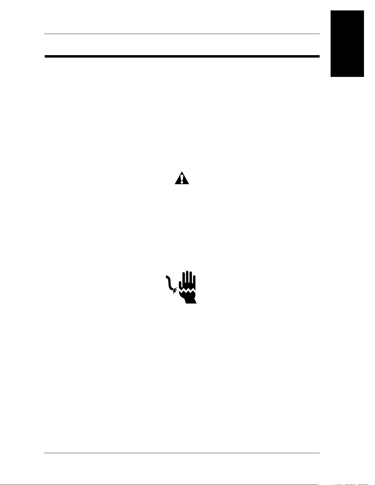
Bed Positions
The ResidentTM LTC manual drive bed has three adjustable sections: head,
knee, and hilow. The bed positions are shown in figures 1-3 through 1-7.
Figure 1-3. Hilow Limits of the Manual Drive Bed (High Position)
Head end
TM
LTC Manual Drive Bed
Foot end
Head end
29.9"
(75.9 cm)
m136_108
Figure 1-4. Hilow Limits of the Manual Drive Bed (Low Position)
Foot end
13.9"
(35.3 cm
Page 1 - 8 ResidentTM LTC Bed Service Manual (man136rc)
Introduction to the Resident
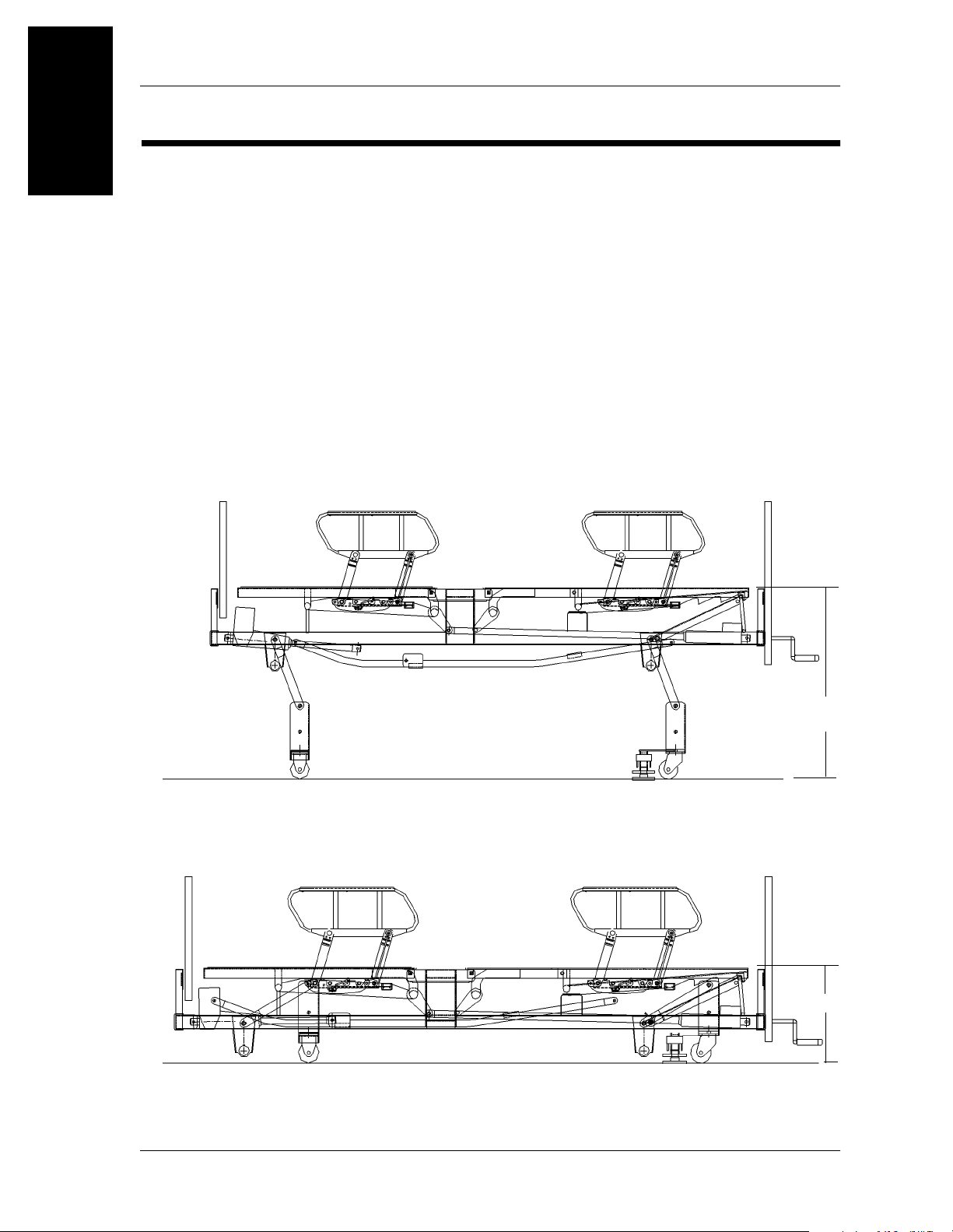
Figure 1-5. Head Section Position of the Manual Drive Bed
TM
LTC Manual Drive Bed
Chapter 1: Introduction
1
Head end
Foot end
m136b005
Head end
Figure 1-6. Knee Section Position of the Manual Drive Bed
Foot end
m136_110
ResidentTM LTC Bed Service Manual (man136rc) Page 1 - 9
1
Resident
Chapter 1: Introduction
TM
LTC Manual Drive Bed Specifications
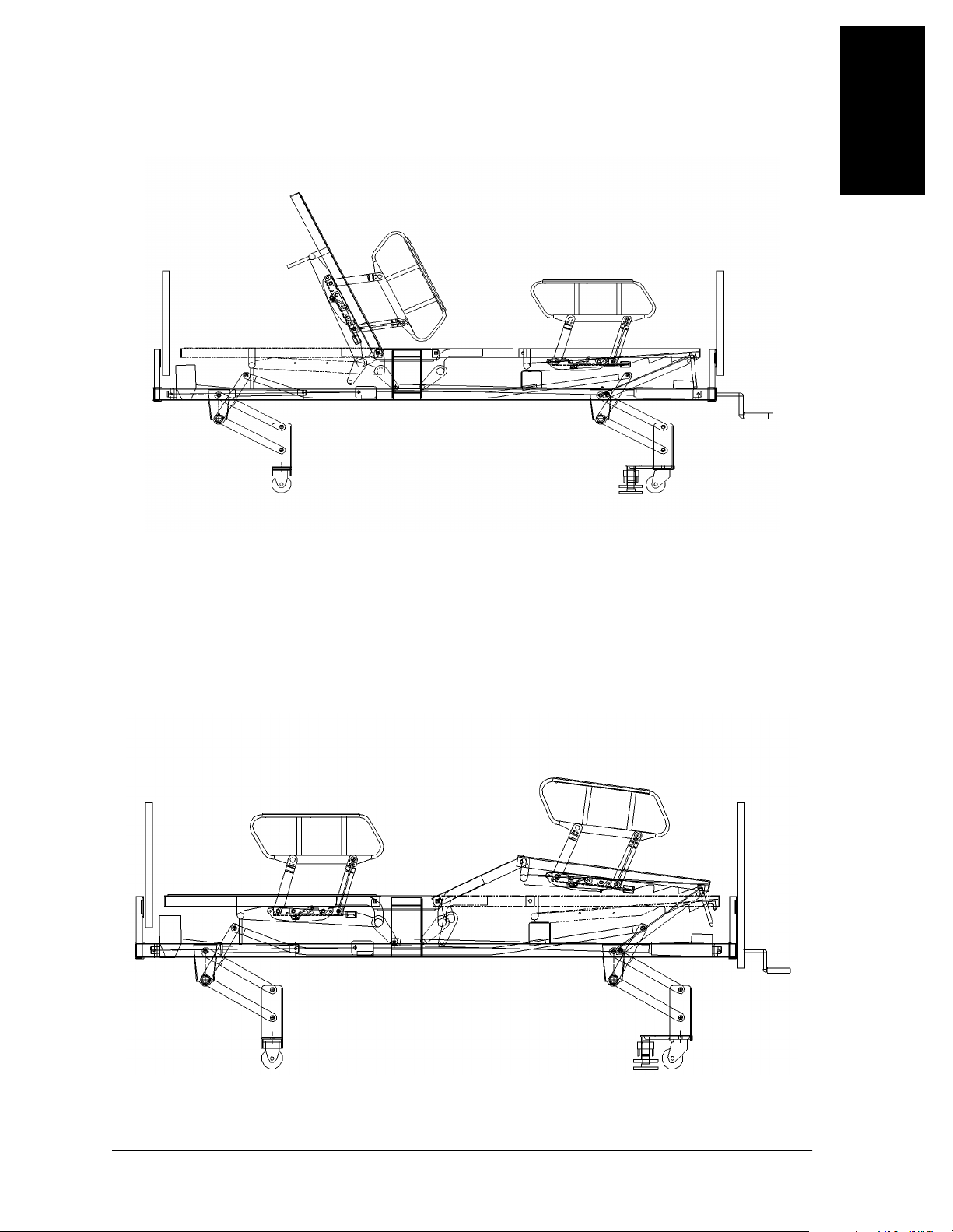
Figure 1-7. Knee Gatch (Foot Section) Position of the Manual Drive Bed
Head end
Resident
Physical Description
Foot end
m136_111
TM
LTC Manual Drive Bed Specifications
See table 1-1 on page 1-10 for ResidentTM LTC manual drive bed specifications.
Table 1-1. ResidentTM LTC Manual drive Bed Specifications
Feature Dimension
Overall length in high position 95 1/4" (241.9 cm)
Overall length in low position 91 1/2" (232.4 cm)
Overall width (siderails up) 42" (106.7 cm)
Overall width (siderails stored) 36" (91.4 cm)
Sleep surface frame height (low position) 13.9" (35.3 cm)
Sleep surface frame height (high position) 29.9" (75.9 cm)
Minimum under bed clearance 5" (12.7 cm)
Maximum head incline elevation 60
Maximum knee incline elevation 45
o
o
Siderail height above sleep surface frame 12 1/2" (31.8 cm)
Bed mass (weight) 275 lb (124.7 kg)
Maximum safe working load—One 400 lb
480 lb (217.7 kg)
(181.4 kg) resident plus accessories
Page 1 - 10 ResidentTM LTC Bed Service Manual (man136rc)

Resident
NOTE:
The head section, knee section, and hilow functions of the ResidentTM LTC
manual drive bed are adjusted by manipulating the hand cranks located at the
foot end of the bed.
WARNING:
Electric or manual drive bed mechanisms can cause serious injury if
operated improperly. Operate the bed only when persons are clear of
the mechanisms.
Head Section Inclination
The head section of the bed may be separately adjusted to obtain the desired
degree of incline up to its limit of approximately 60o (± 2o). The head section
control is a hand crank located at the foot end of the bed.
Head Angle Indicators
TM
LTC Manual Drive Bed Specifications
Chapter 1: Introduction
1
The head angle indicator decals are located at both sides of the bed on the sleep
surface. These indicators provide a reference for approximately each 15o of
head section incline up to 60o.
Knee Section Inclination
The knee section of the bed may be separately adjusted to obtain the desired
degree of incline up to its limit of approximately 45o (± 2o). The knee section
control is a hand crank located at the foot end of the bed.
Hilow
The bed may be adjusted to raise or lower the sleep surface to assist in
positioning the resident, or for ease of bed entry/exit. Hilow is adjusted by
means of a hand crank located at the foot end of the bed.
Steering
Swivel casters are located on the caster frame beneath the foot section of the
bed. Fixed casters are located on the caster frame beneath the head section of
the bed.
ResidentTM LTC Bed Service Manual (man136rc) Page 1 - 11

1
Resident
Chapter 1: Introduction
TM
LTC Manual Drive Bed Specifications
Brakes
The brakes are located on both sides of the swivel caster frame assembly at the
foot end of the bed. Some models have individually operated brakes and
require that both pedals be pressed and released separately.
Siderails
Siderails are located on both sides of the ResidentTM LTC manual drive bed at
the head and foot sections. The siderails are raised and lowered independently
of each other. When not in use, safely store each siderail beneath the bed’s
sleep surface frame.
Siderails are visual reminders for residents that identify the location of the
edge of the bed. They are not intended for use as a restraint device.
Appropriate medical personnel must determine the level of restraint necessary
to ensure a resident will remain safely in bed. Failure to do so could result in
personal injury.
Bumper
A bumper assembly is secured to the fixed caster frame at the head end of the
bed.
CAUTION:
Removing the bumper assembly could cause damage to the bed or
facility.
IV Rod Sockets
Four IV rod sockets are provided. One is located at each outside corner of the
bed. Each socket allows installation of an IV rod (accessory).
Sleep Surface Support Frame
There are two sleep surface support frames available for use with the
ResidentTM LTC manual drive bed. The mattress supporting spring fabric frame
is 36" x 80" (91.4 cm x 203.2 cm) and has 90 supporting helical springs for the
fabric assembly. The mattress supporting optional hard pan sleep surface frame
is 36" x 80" (91.4 cm x 203.2 cm). The outer surfaces of the panels are formed
down to prevent sharp edges.
Page 1 - 12 ResidentTM LTC Bed Service Manual (man136rc)

Resident
TM
LTC Manual Drive Bed Specifications
Chapter 1: Introduction
Mattress Stop
A separate mattress stop is not available on the manual drive version of the
ResidentTM LTC manual drive bed. The foot panel acts as a mattress stop on this
version preventing the mattress from sliding towards the foot end of the bed.
Mattress Configurations
There are several mattress configurations available for the ResidentTM LTC
manual drive bed. These configurations are indicated in table 1-2 on page 1-13.
Table 1-2. Mattress Options
Product Number Description
P778 LTC mattress
P944 Comfortline
P783 Extended care mattress
P462 (P1416) Unbundled ZoneAire
®
mattress
®
(mattress)
1
Head and Foot Panels
The head and foot panels fit over two vertical post type mountings located at
each end of the bed and are removable by lifting vertically. The hand cranks
must be detached from the manual head, knee, and hilow drive assemblies
before the foot panel can be removed. These panels provide ease of bed
mobility and steering control.
Drainage Bag Hooks
Drainage bag hooks are located on both sides of the bed beneath the sleep
surface frame near the seat section.
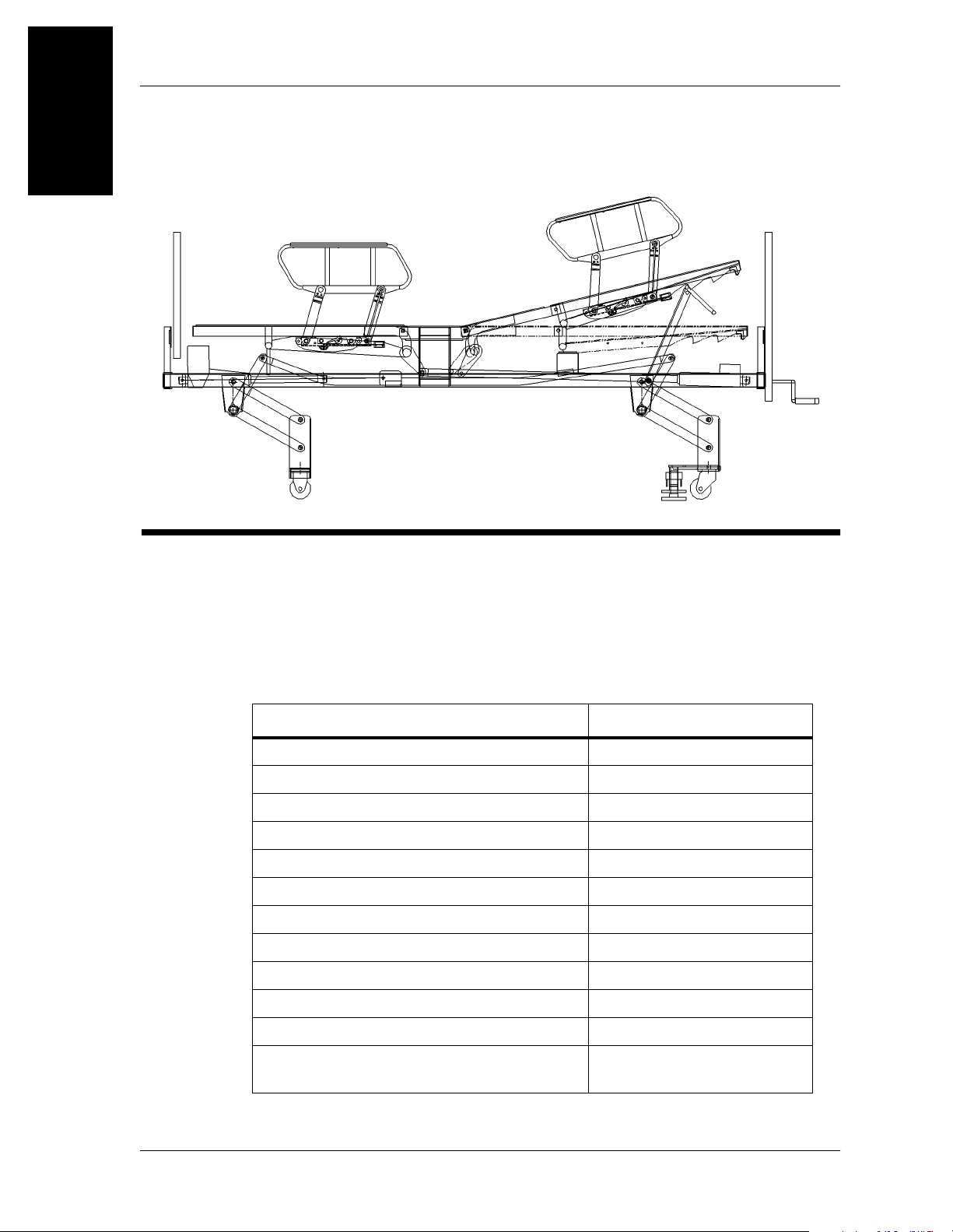
Mechanical Description
The ResidentTM LTC manual drive bed is manually adjusted by manipulating
the head, knee, and hilow drive assemblies.
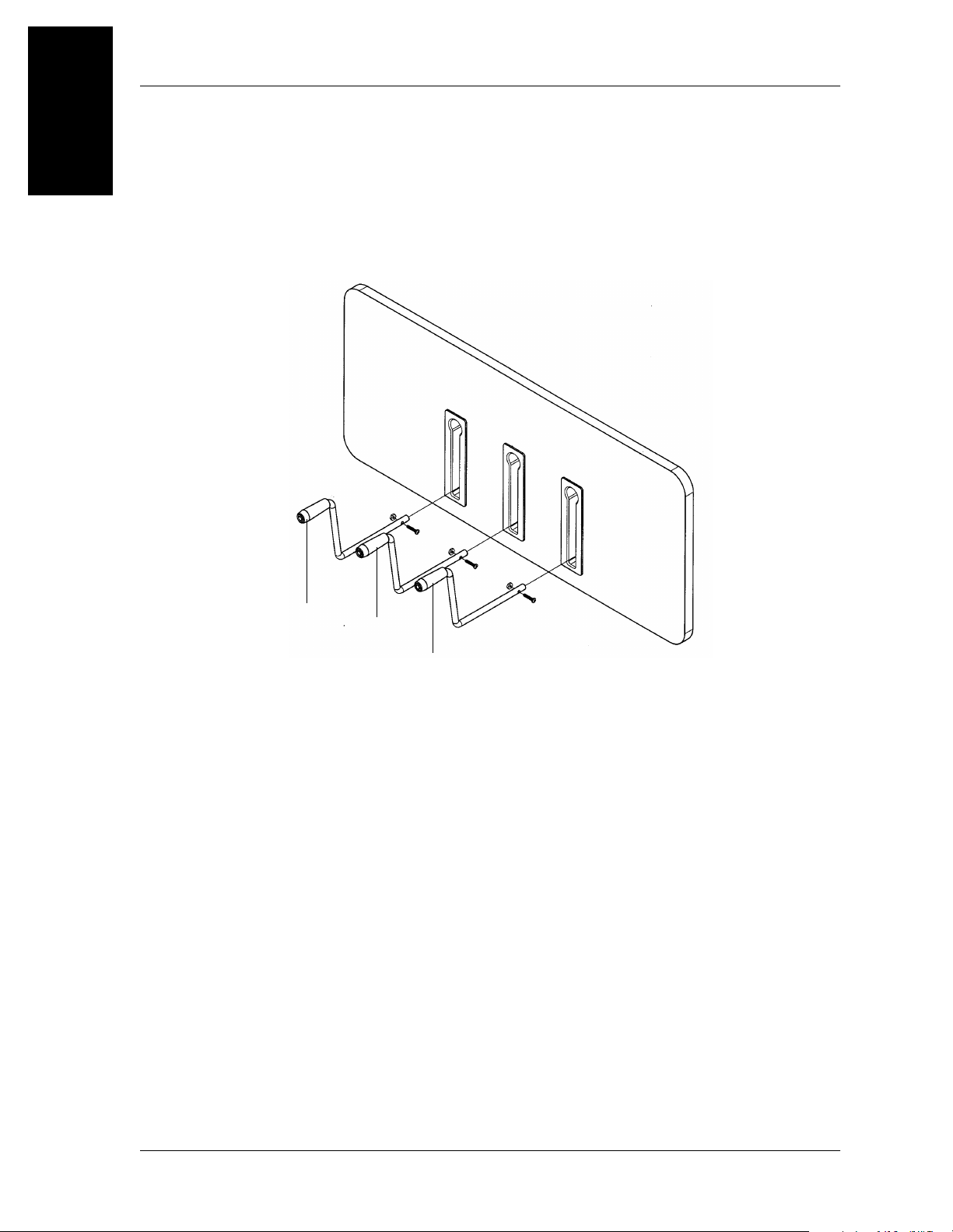
Caregiver manual crank controls are located at the foot end of the bed (see
figure 1-8 on page 1-14). These crank handles allow the caregiver to manually
operate the head section, knee section, and hilow (bed height) to obtain the
desired elevation within their respective travel limits. They can be tucked away
in recesses in the footboard when not in use.
ResidentTM LTC Bed Service Manual (man136rc) Page 1 - 13
1
Resident
Chapter 1: Introduction
TM
LTC Manual Drive Bed Specifications
The head section can be adjusted by turning the right crank handle (A), the
knee section can be adjusted by turning the left crank handle (B), and the hilow
function is adjusted by turning the middle crank handle (C) (see figure 1-8 on
page 1-14).
Figure 1-8. Crank Handle Configuration for the Manual Drive Bed
A
C
B
Page 1 - 14 ResidentTM LTC Bed Service Manual (man136rc)

General Operation of the ResidentTM LTC Manual Drive Bed
General Operation of the Resident
Siderail Operation
WARNING:
Siderails are visual reminders for residents that identify the
location of the edge of the bed. They are not intended for use as a
restraint device. Appropriate medical personnel must determine the
level of restraint necessary to ensure a resident will remain safely in
bed. Failure to do so could result in personal injury.
Raise the Siderail
• Grasp the siderail, and pull it outward from its stored position beneath the
sleep surface frame.
• If the siderail is at the head end, rotate the siderail toward the head end of
the bed to its fully raised position.
Chapter 1: Introduction
TM
LTC Manual Drive Bed
1
• If the siderail is at the foot end, rotate the siderail toward the foot end of the
bed to its fully raised position.
• An audible click indicates that the siderail is completely raised and locked
in place. To ensure the siderail is latched, give it a tug in the downward
direction.
Lower the Siderail
• Grasp the siderail with one hand, and push inward on the release latch with
the other.
• Rotate the siderail to its lowered position (rotate toward the head if at head
end, and toward the foot if at the foot end of the bed).
• Push the siderail into its stored position beneath the sleep surface frame.
ResidentTM LTC Bed Service Manual (man136rc) Page 1 - 15

1
General Operation of the ResidentTM LTC Manual Drive Bed
Chapter 1: Introduction
Bed Positions
WARNING:
Manual drive bed mechanisms can cause serious injury. Operate the
bed only when persons are clear of the mechanisms.
Hilow
To raise the bed, locate the middle hand crank at the foot end of the bed. Turn
the handle clockwise until the desired height is achieved.
To lower the bed, turn the middle hand crank at the foot end of the bed
counterclockwise until the desired height is achieved.
Head Section
To raise the head section, locate the right hand crank at the foot end of the bed.
Turn the handle clockwise until the desired incline is achieved.
To lower the head section, turn the right hand crank at the foot end of the bed
counterclockwise until the desired incline is achieved.
Knee Section
To elevate the knee section, turn the left hand crank at the foot end of the bed
clockwise until the desired incline is achieved.
To lower the knee section, turn the left hand crank at the foot end of the bed
counterclockwise until the desired incline is achieved.
Steering
WARNING:
When moving the bed, guide it from the corners near the foot end of the
bed! This will help keep legs clear of the frame and feet clear of the
caster base. The ResidentTM LTC bed is not intended to be used as a
resident transport device.
Page 1 - 16 ResidentTM LTC Bed Service Manual (man136rc)

Brakes
WARNING:
Set the brakes, and leave the bed in the low position when the resident
is unattended. A resident might use the bed for support when getting on
or off of the sleep surface. Give the bed a solid tug to ensure the brakes
are set. Injury to the resident may occur if the brakes are not set.
Apply the brakes by depressing the brake pedal(s) with your foot.
Release the brakes by depressing the release arm next to the brake pedal.
Head and Foot Panels
To remove the head or foot panel, lift it straight up until the mounting plates on
the panel disengage the plates welded to the IV rod sockets. Before removing
the foot panel, the hand cranks must be removed. Remove the crank handle
assemblies for the head, knee, and hilow drives by removing the nut and bolt
located at the base of each crank handle. Set panels aside in an area where they
will not be damaged.
General Operation of the ResidentTM LTC Manual Drive Bed
Chapter 1: Introduction
1
To install either panel, align the mounting plates on the panel with the metal
plates on the IV rod sockets. Lower the panel downward to engage. Once the
foot panel is in place, attach the crank handle assemblies to the head, knee, and
hilow drives through the slots in the mounted foot panel. Insert the screw and
nut at the base of each crank handle and tighten with a wrench.
ResidentTM LTC Bed Service Manual (man136rc) Page 1 - 17
 Loading...