

Page 1

Video Intercom Module Door Station
User Manual
Page 2
Video Intercom Module Door Station·User Manual
User Manual
© 2018 Hangzhou Hikvision Digital Technology Co., Ltd.
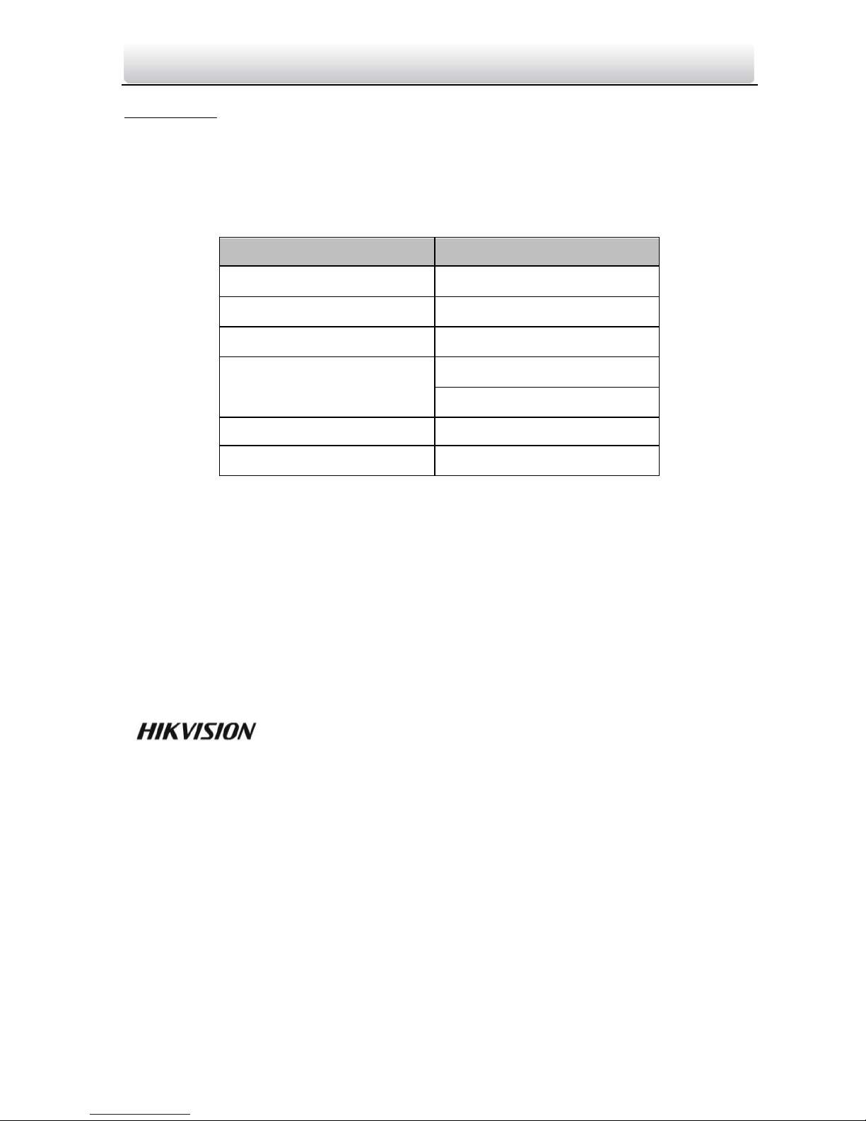
This user manual is intended for users of module door station.
The door station supports custom combination. You can choose from the modules listed
below according to needs.
Name
Model
Main Unit
DS-KD8003-IME1
Nametag Module
DS-KD-KK
Keypad Module
DS-KD-KP
Card Reader Module
DS-KD-M(13.56 MHz)
DS-KD-E(125 KHz)
Indicator Module
DS-KD-IN
Blank Module
DS-KD-BK
It includes instructions on how to use the Product. The software embodied in the
Product is governed by the user license agreement covering that Product.
About this Manual
This Manual is subject to domestic and international copyright protection. Hangzhou
Hikvision Digital Technology Co., Ltd. (“Hikvision”) reserves all rights to this manual. This
manual cannot be reproduced, changed, translated, or distributed, partially or wholly, by
any means, without the prior written permission of Hikvision.
Trademarks
and other Hikvision marks are the property of Hikvision and are
registered trademarks or the subject of applications for the same by Hikvision and/or its
affiliates. Other trademarks mentioned in this manual are the properties of their
respective owners. No right of license is given to use such trademarks without express
permission.
Disclaimer
TO THE MAXIMUM EXTENT PERMITTED BY APPLICABLE LAW, HIKVISION MAKES NO WARRANTIES,
EXPRESS OR IMPLIED, INCLUDING WITHOUT LIMITATION THE IMPLIED WARRANTIES OF
MERCHANTABILITY AND FITNESS FOR A PARTICULAR PURPOSE, REGARDING THIS MANUAL.
HIKVISION DOES NOT WARRANT, GUARANTEE, OR MAKE ANY REPRESENTATIONS REGARDING THE
USE OF THE MANUAL, OR THE CORRECTNESS, ACCURACY, OR RELIABILITY OF INFORMATION
CONTAINED HEREIN. YOUR USE OF THIS MANUAL AND ANY RELIANCE ON THIS MANUAL SHALL BE
WHOLLY AT YOUR OWN RISK AND RESPONSIBILITY.
Page 3

Video Intercom Module Door Station·User Manual
TO THE MAXIMUM EXTENT PERMITTED BY APPLICABLE LAW, IN NO EVENT WILL HIKVISION, ITS
DIRECTORS, OFFICERS, EMPLOYEES, OR AGENTS BE LIABLE TO YOU FOR ANY SPECIAL,
CONSEQUENTIAL, INCIDENTAL, OR INDIRECT DAMAGES, INCLUDING, AMONG OTHERS, DAMAGES
FOR LOSS OF BUSINESS PROFITS, BUSINESS INTERRUPTION, SECURITY BREACHES, OR LOSS OF DATA
OR DOCUMENTATION, IN CONNECTION WITH THE USE OF OR RELIANCE ON THIS MANUAL, EVEN IF
HIKVISION HAS BEEN ADVISED OF THE POSSIBILITY OF SUCH DAMAGES.
SOME JURISDICTIONS DO NOT ALLOW THE EXCLUSION OR LIMITATION OF LIABILITY OR CERTAIN
DAMAGES, SO SOME OR ALL OF THE ABOVE EXCLUSIONS OR LIMITATIONS MAY NOT APPLY TO YOU.
Support
Should you have any questions, please do not hesitate to contact your local dealer.
Page 4
Video Intercom Module Door Station·User Manual
Regulatory Information
FCC Information
Please take attention that changes or modification not expressly approved by the party
responsible for compliance could void the user’s authority to operate the equipment.
FCC compliance: This equipment has been tested and found to comply with the limits
for a Class B digital device, pursuant to part 15 of the FCC Rules. These limits are
designed to provide reasonable protection against harmful interference in a residential
installation. This equipment generates, uses and can radiate radio frequency energy and,
if not installed and used in accordance with the instructions, may cause harmful
interference to radio communications. However, there is no guarantee that interference
will not occur in a particular installation. If this equipment does cause harmful
interference to radio or television reception, which can be determined by turning the
equipment off and on, the user is encouraged to try to correct the interference by one
or more of the following measures:
—Reorient or relocate the receiving antenna.
—Increase the separation between the equipment and receiver.
—Connect the equipment into an outlet on a circuit different from that to which the
receiver is connected.
—Consult the dealer or an experienced radio/TV technician for help.
FCC Conditions
This device complies with part 15 of the FCC Rules. Operation is subject to the following
two conditions:
1. This device may not cause harmful interference.
2. This device must accept any interference received, including interference that may
cause undesired operation.
EU Conformity Statement
This product and - if applicable - the supplied accessories too are
marked with "CE" and comply therefore with the applicable
harmonized European standards listed under the EMC Directive
2014/30/EU, LVD Directive 2014/35/EU, the RoHS Directive 2011/65/EU.
2012/19/EU (WEEE directive): Products marked with this symbol
cannot be disposed of as unsorted municipal waste in the European
Union. For proper recycling, return this product to your local supplier
upon the purchase of equivalent new equipment, or dispose of it at
designated collection points. For more information see:
www.recyclethis.info
Page 5

Video Intercom Module Door Station·User Manual
2006/66/EC (battery directive): This product contains a battery that
cannot be disposed of as unsorted municipal waste in the European
Union. See the product documentation for specific battery information.
The battery is marked with this symbol, which may include lettering to
indicate cadmium (Cd), lead (Pb), or mercury (Hg). For proper recycling,
return the battery to your supplier or to a designated collection point.
For more information see: www.recyclethis.info
Page 6
Video Intercom Module Door Station·User Manual
Safety Instruction
These instructions are intended to ensure that user can use the product correctly to
avoid danger or property loss.
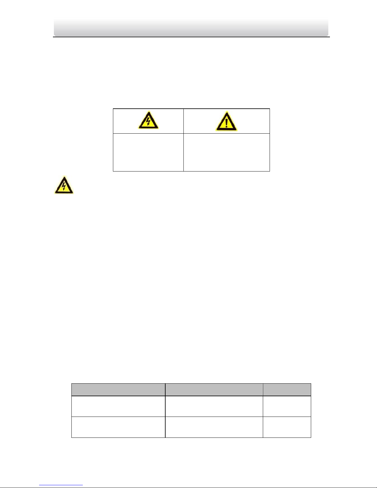
The precaution measure is divided into Warnings and Cautions:
Warnings: Neglecting any of the warnings may cause serious injury or death.
Cautions: Neglecting any of the cautions may cause injury or equipment damage.
Warnings
The working temperature of the device is from -40º C to 60º C.
All the electronic operation should be strictly compliance with the electrical safety
regulations, fire prevention regulations and other related regulations in your local
region.
Please use the power adapter, which is provided by normal company. The power
consumption cannot be less than the required value.
Do not connect several devices to one power adapter as adapter overload may cause
over-heat or fire hazard.
Please make sure that the power has been disconnected before you wire, install or
dismantle the device.
When the product is installed on wall or ceiling, the device shall be firmly fixed.
If smoke, odors or noise rise from the device, turn off the power at once and unplug
the power cable, and then please contact the service center.
If the product does not work properly, please contact your dealer or the nearest
service center. Never attempt to disassemble the device yourself. (We shall not
assume any responsibility for problems caused by unauthorized repair or
maintenance.)
The power supply must conform to LPS. The recommended adaptor models and
manufacturers are shown as below. Use the attached adaptor, and do not change the
adaptor randomly.
Model
Manufacturer
Standard
ADS-24S-12 1224GPCN
Shenzhen Honor Electronic
Co., Ltd.
GB
KPL-060F-VI
Channel Well Technology
Co., Ltd.
GB
Warnings Follow
these safeguards to
prevent serious
injury or death.
Cautions Follow these
precautions to prevent
potential injury or
material damage.
Page 7

Video Intercom Module Door Station·User Manual
Cautions
Do not drop the device or subject it to physical shock, and do not expose it to high
electromagnetism radiation. Avoid the equipment installation on vibrations surface or
places subject to shock (ignorance can cause equipment damage).
Do not place the device in extremely hot (refer to the specification of the device for
the detailed operating temperature), cold, dusty or damp locations, and do not
expose it to high electromagnetic radiation.
Do not aim the device at the sun or extra bright places. A blooming or smear may
occur otherwise (which is not a malfunction however), and affecting the endurance of
sensor at the same time.
Please use a soft and dry cloth when clean inside and outside surfaces of the device
cover, do not use alkaline detergents.
Please keep all wrappers after unpack them for future use. In case of any failure
occurred, you need to return the device to the factory with the original wrapper.
Transportation without the original wrapper may result in damage on the device and
lead to additional costs.
Improper use or replacement of the battery may result in hazard of explosion.
Replace with the same or equivalent type only. Dispose of used batteries according to
the instructions provided by the battery manufacturer.
The warranty does not apply to the product defects and failures arisen as a result of
improper mounting (in contradiction herewith).
When the proper mounting instructions are not met, water might get in and destroy
the electronics.
Page 8

Video Intercom Module Door Station·User Manual
Table of Contents
1 Overview ...................................................................................................... 1
1.1 Introduction ............................................................................................................. 1
1.2 Main Features .......................................................................................................... 1
1.3 Typical Application ................................................................................................... 2
2 Appearance .................................................................................................. 3
2.1 Main Unit ................................................................................................................. 3
2.2 Nametag Module ..................................................................................................... 4
2.3 Keypad Module ........................................................................................................ 5
2.4 Indicator Module ..................................................................................................... 5
2.5 Card Reader Module ................................................................................................ 6
2.6 Blank Module........................................................................................................... 7
3 Terminal and Wiring ..................................................................................... 8
3.1 Terminal Description ................................................................................................ 8
3.1.1 Main Unit .......................................................................................................... 8
3.1.2 Sub Module ....................................................................................................... 9
3.2 Wiring Description ................................................................................................. 10
3.2.3 Door Lock Wiring ............................................................................................ 10
3.2.4 Door Magnetic Wiring ..................................................................................... 11
3.2.5 Exit Button Wiring ........................................................................................... 11
4 Installation ................................................................................................. 13
4.1 Configure Sub Module Address ............................................................................. 13
4.2 One-Module Installation ........................................................................................ 14
4.2.1 Installation Accessory Description................................................................... 14
4.2.2 One-Module Surface Mounting....................................................................... 15
4.2.3 One-Module Flush Mounting ...........................................................................17
4.3 Two-Module Installation ........................................................................................ 21
4.3.1 Installation Accessory Description................................................................... 21
4.3.2 Two-Module Surface Mounting ...................................................................... 21
4.3.3 Two-Module Flush Mounting .......................................................................... 25
4.4 Three-Module Installation ..................................................................................... 29
4.4.1 Installation Accessory Description................................................................... 29
4.4.2 Three-Module Surface Mounting .................................................................... 30
4.4.3 Three-Module Flush Mounting ....................................................................... 34
4.5 More-than-Three Module Installation ................................................................... 40
4.5.1 Installation Accessory Description................................................................... 40
4.5.2 More-than-Three Module Surface Mounting .................................................. 40
4.5.3 More-than-Four Module Flush Mounting ....................................................... 46
5 Device Configuration .................................................................................. 55
5.1 Activate Device ...................................................................................................... 55
Page 9

Video Intercom Module Door Station·User Manual
5.2 Edit Network Parameters ....................................................................................... 56
5.3 Add Device .............................................................................................................. 57
5.4 Reset Password ...................................................................................................... 59
5.5 Configure System Parameters ................................................................................ 61
5.5.1 Device Information .......................................................................................... 61
5.5.2 General ............................................................................................................ 61
5.5.3 Time ................................................................................................................ 61
5.5.4 System Maintenance ........................................................................................62
5.5.5 User ................................................................................................................. 64
5.6 Configure Video Intercom Parameters .................................................................. 65
5.6.1 Device ID Configuration .................................................................................. 65
5.6.2 Time Parameters ............................................................................................. 66
5.6.3 Access Control and Elevator ............................................................................ 66
5.6.4 IO Input and Output ........................................................................................ 68
5.6.5 Volume Input and Output ............................................................................... 69
5.6.6 Dial .................................................................................................................. 69
5.6.7 Sub Module ..................................................................................................... 69
5.7 Configure Video Intercom Network ........................................................................70
5.7.1 Local Network Configuration ............................................................................70
5.7.2 Linked Devices Network Configuration ........................................................... 71
5.7.3 FTP ...................................................................................................................72
5.7.4 Advanced Settings ........................................................................................... 73
5.8 Video Display ......................................................................................................... 73
5.8.1 Video Parameters ............................................................................................ 73
5.8.2 Video & Audio .................................................................................................. 74
6 Video Intercom Operation .......................................................................... 76
6.1 Video Intercom Operation via Device .....................................................................76
6.2 Video Intercom Operation via iVMS-4200 ..............................................................76
6.2.1 Receive Call from Door Station.........................................................................76
6.2.2 View Live Video of Door Station ......................................................................78
6.2.3 View Call Logs ..................................................................................................78
6.2.4 Search Video Intercom Information ................................................................ 79
Page 10

Video Intercom Module Door Station·User Manual
1 Overview
1.1 Introduction
The video intercom module door station can realize functions such as video intercom,
resident-to-resident video call to provide a complete smart community video intercom
solution.
The video intercom module door station is mainly applied to situations such as
community, villa, and official buildings.
1.2 Main Features
2MP HD video intercom function
Access control function
Fisheye camera with IR supplement light
Tampering alarm and door magnetic alarm supported
Supports sub-modules’ access (max.8)
Noise suppression and echo cancellation
Easy to extend
Page 11
Video Intercom Module Door Station·User Manual
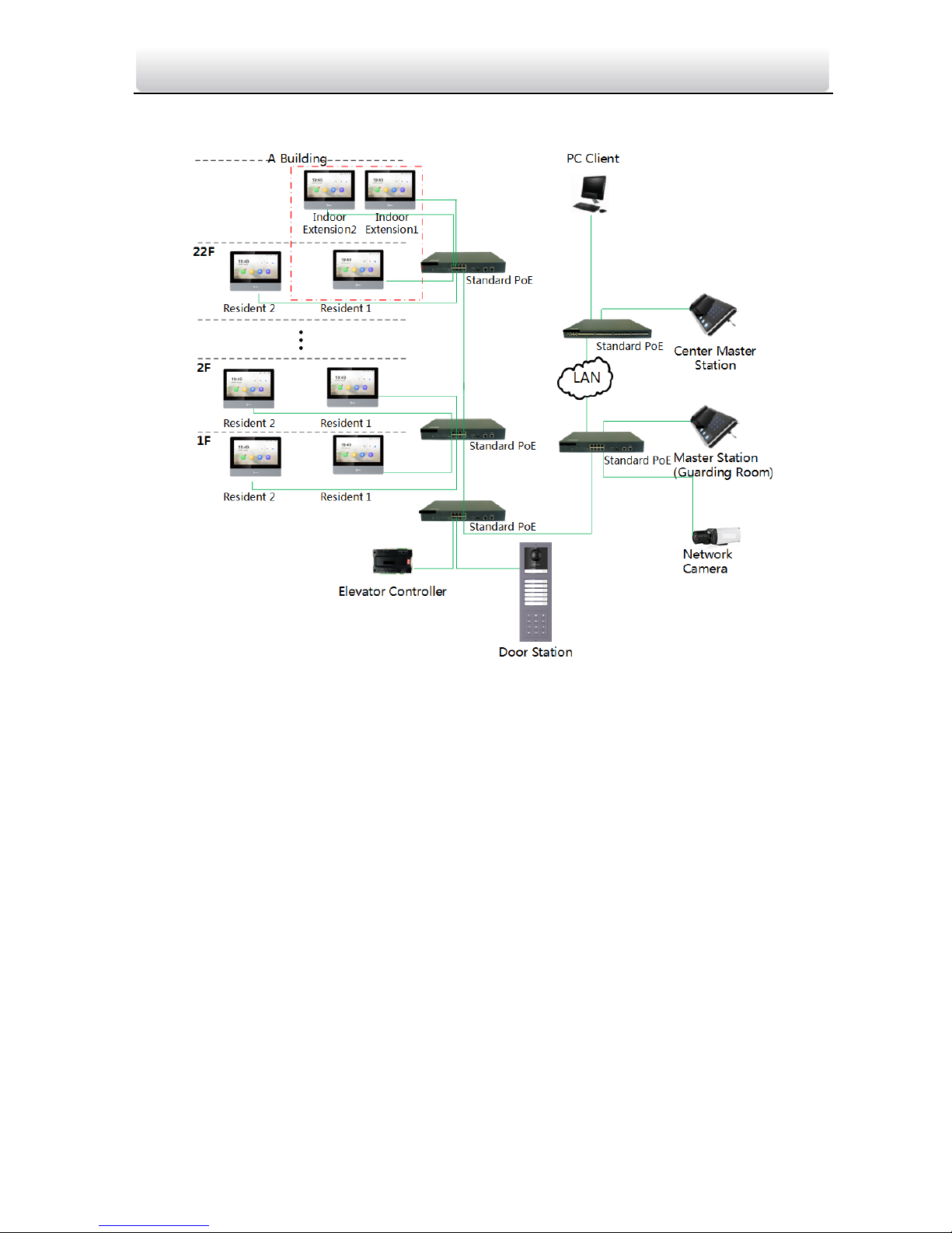
1.3 Typical Application
Figure 1-1 Typical Application
Page 12
Video Intercom Module Door Station·User Manual
2 Appearance
2.1 Main Unit
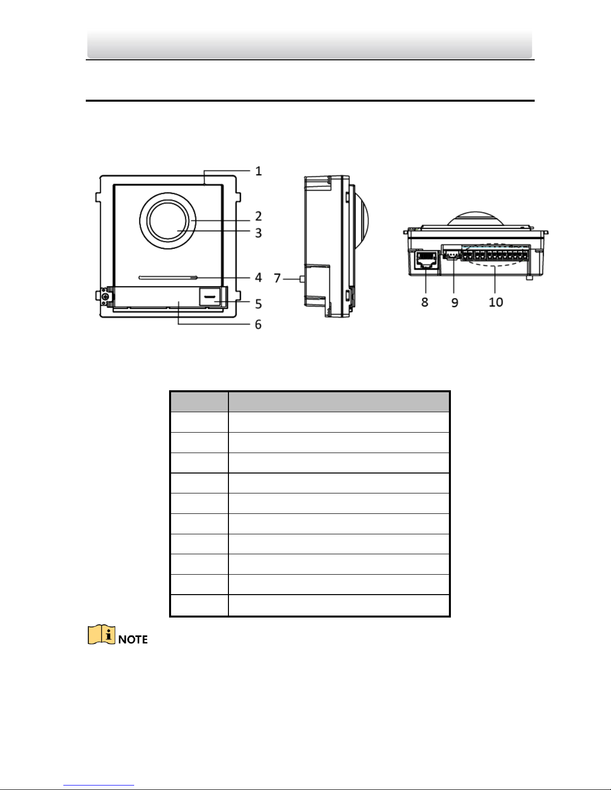
Figure 2-1 Main Unit Appearance
Table 2-1 Appearance Description
No.
Description
1
Microphone
2
Low Illumination IR Supplement Light
3
Built-in Camera
4
Loudspeaker
5
Call Button
6
Nametag
7
TAMPER
8
Network Interface
9
Module-connecting Interface(output)
10
Terminals
Nametag area supports insert customized name card.
The suggested card size is: 58 (L) x 11.7(W) mm.
Page 13

Video Intercom Module Door Station·User Manual
2.2 Nametag Module
Figure 2-2 Nametag Module Appearance
Table 2-2 Appearance Description
No.
Description
1
Call Button
2
Nametag
3
Module-connecting Interface(output)
4
Module-connecting Interface(input)
5
Debug Port
Nametag area supports insert customized name card.
The suggested card size is: 58 (L) x 11.7(W) mm.
Page 14
Video Intercom Module Door Station·User Manual
2.3 Keypad Module
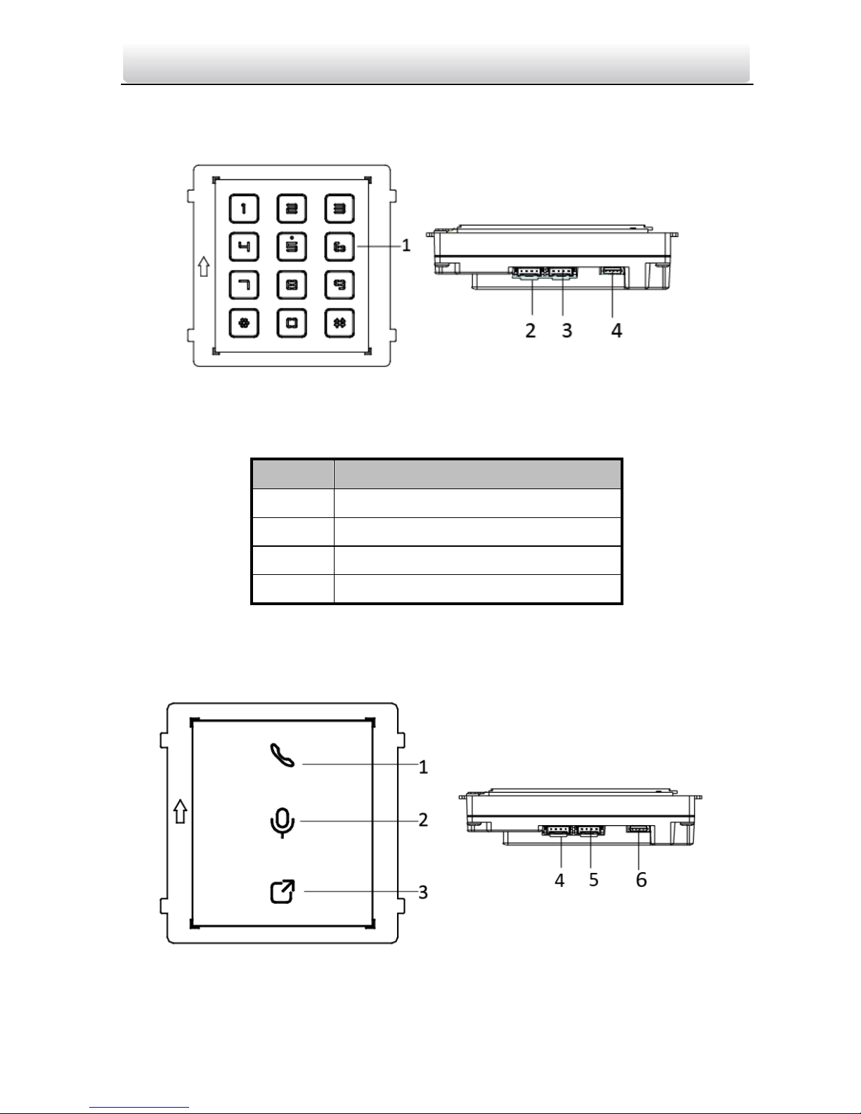
Figure 2-3 Keypad Module Appearance
Table 2-3 Appearance Description
No.
Description
1
Button
2
Module-connecting Interface(output)
3
Module-connecting Interface(input)
4
Debug Port
2.4 Indicator Module
Figure 2-4 Keypad Module Appearance
Page 15
Video Intercom Module Door Station·User Manual
Table 2-4 Appearance Description
No.
Description
1
Indicator1(Solid yellow during calling)
2
Indicator2(Solid white during two-way audio)
3
Indicator3(Solid blue when door is open)
4
Module-connecting Interface(output)
5
Module-connecting Interface(input)
6
Debug Port
2.5 Card Reader Module
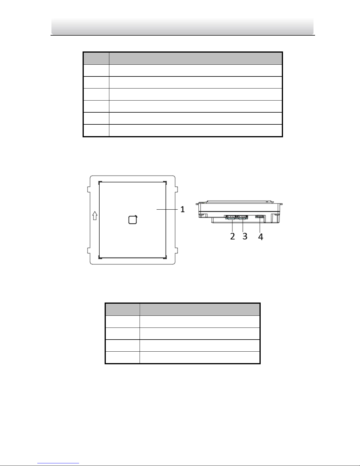
Figure 2-5 Card Reader Module Appearance
Table 2-5 Appearance Description
No.
Description
1
Card Reading Area
2
Module-connecting Interface(output)
3
Module-connecting Interface(input)
4
Debug Port
Page 16
Video Intercom Module Door Station·User Manual
2.6 Blank Module
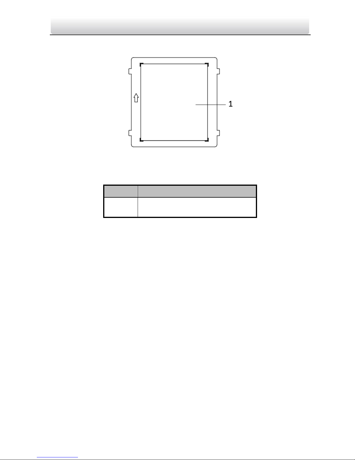
Figure 2-6 Blank Module Appearance
Table 2-6 Appearance Description
No.
Description
1
Supports to insert customized
information card
Page 17
Video Intercom Module Door Station·User Manual
3 Terminal and Wiring
3.1 Terminal Description
3.1.1 Main Unit
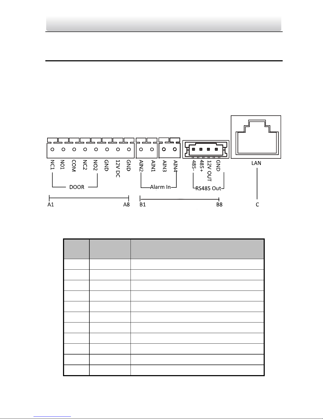
Figure 3-1 Terminals and Interfaces
Table 3-1 Descriptions of Terminals and Interfaces
No.
Interface
Description
A1
NC1
Door Lock Relay Output (NC)
A2
NO1
Door Lock Relay Output (NO)
A3
COM
Common Interface
A4
NC2
Door Lock Relay Output (NC)
A5
NO2
Door Lock Relay Output (NO)
A6
GND
Grounding
A7
12V DC
Power Supply Output
A8
GND
Grounding
B1
AIN2
For the access of Door Magnetic2
B2
AIN1
For the access of Door Magnetic1
B3
AIN3
For the access of Exit Button 1
Page 18
Video Intercom Module Door Station·User Manual
No.
Interface
Description
B4
AIN4
For the access of Exit Button 2
B5
485-
Module-connecting Interface
B6
485+
B7
12V OUT
B8
GND
C
LAN
PoE Network Interface(Supports IEEE
802.3af/at-Compliant Devices)
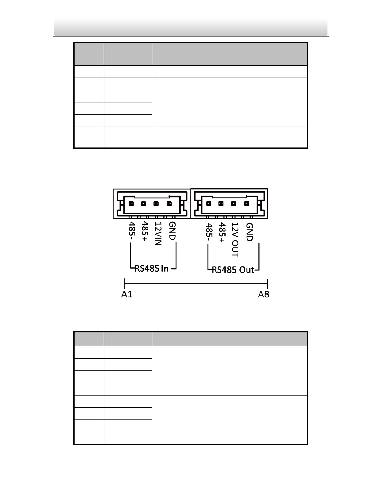
3.1.2 Sub Module
All the modules except the main work as the sub module. The sub module’s interfaces
and terminals as below:
Figure 3-2 Terminals and Interfaces
Table 3-2 Descriptions of Terminals and Interfaces
No.
Interface
Description
A1
485-
Module-connecting Interface (Input)
A2
485+
A3
12V IN
A4
GND
A5
485-
Module-connecting Interface (Output)
A6
485+
A7
12V OUT
A8
GND
Page 19
Video Intercom Module Door Station·User Manual
3.2 Wiring Description
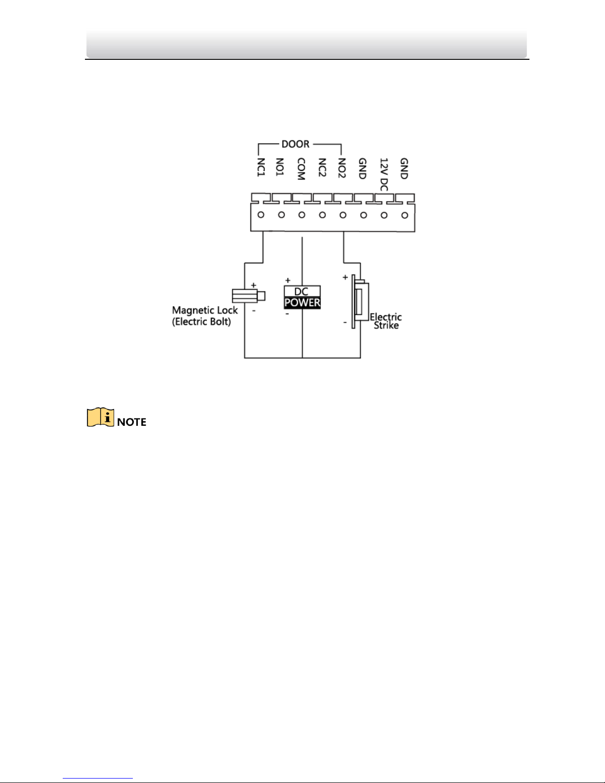
3.2.3 Door Lock Wiring
Figure 3-3 Door Lock Wiring
Terminal NC1/COM is set as default for accessing magnetic lock/electric bolt; terminal
NO2/COM is set as default for accessing electric strike.
Lock should be powered by itself. Max. voltage and current for relay is 30V and 1A.
Page 20
Video Intercom Module Door Station·User Manual
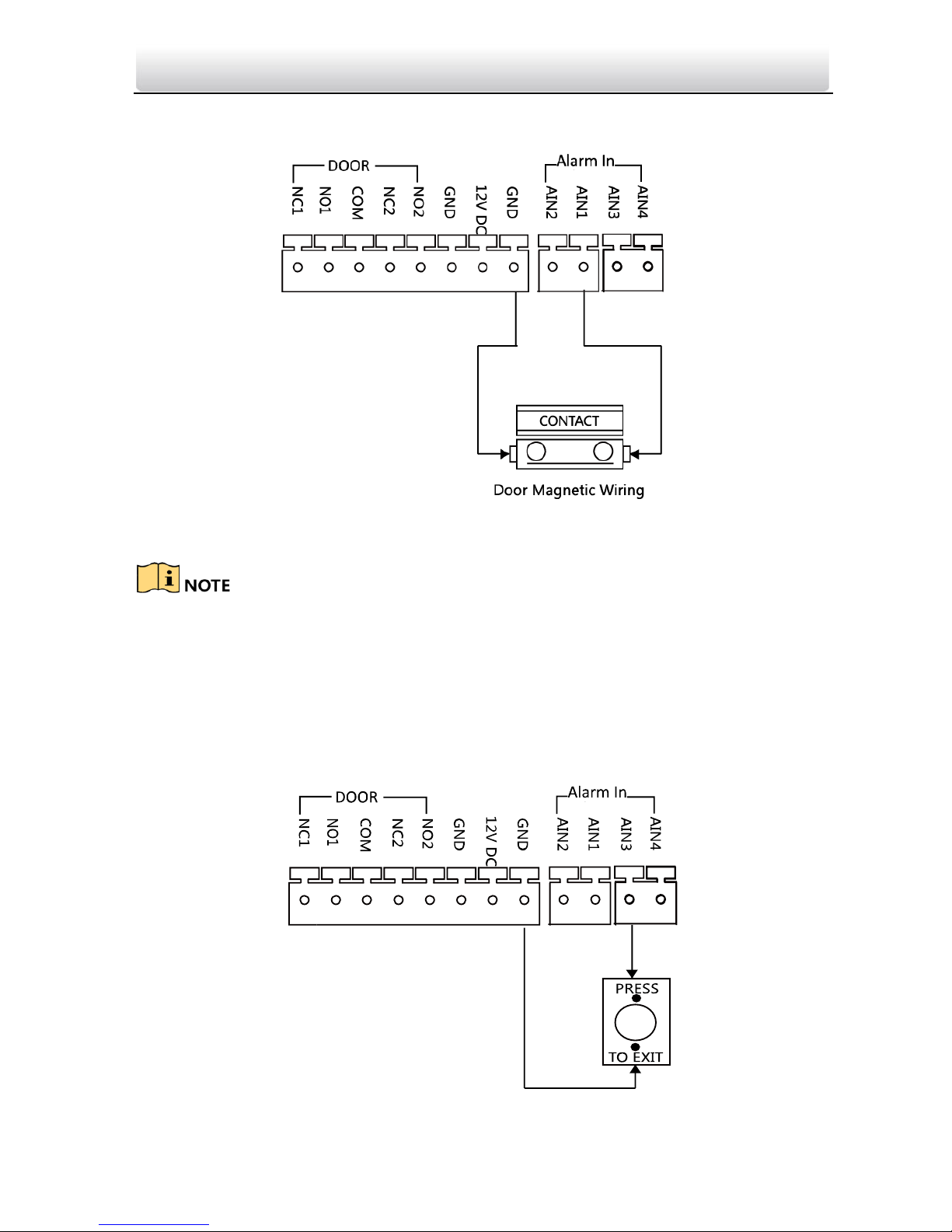
3.2.4 Door Magnetic Wiring
Figure 3-4 Door Magnetic Wiring
AIN1 and AIN2 are defaulted to connect door magnetic. Door magnetic connected to
AIN1 detects status of the lock that connected to NC1/NO1; Door magnetic connected to
AIN2 detects the status of the lock connected to NC2/NO2.
3.2.5 Exit Button Wiring
Figure 3-5 Exit Button Wiring
Page 21

Video Intercom Module Door Station·User Manual
AIN3 and AIN4 are set as default for connecting exit button. Exit button connected to
AIN3 opens the lock connected to NC1/NO1; Exit button connected to AIN4 controls the
lock that connected to NC2/NO2.
Page 22

Video Intercom Module Door Station·User Manual
4 Installation
Before you start:
Make sure the device in the package is in good condition and all the assembly parts
are included.
Set the sub module address before start the installation steps.
Make sure the place for surface mounting is flat.
Make sure all the related equipment is power-off during the installation.
Tools that you need to prepare for installation:
Drill (ø6), cross screwdriver (PH1*150 mm), and gradienter.
Buy corresponding accessory package for installation. The accessory package model
and its suitable installation method as below:
Package
Model
Mounting Method
Note
DS-KD-ACW1
One-Module Surface Mounting
Install the device according
to the instructions.
Not all the lines in the
accessory package will be
used.
DS-KD-ACW2
Two-Module Surface Mounting
DS-KD-ACW3
Three-Module Surface Mounting
DS-KD-ACF1
One-Module Flush Mounting
DS-KD-ACF2
Two-Module Flush Mounting
DS-KD-ACF3
Three-Module Flush Mounting
4.1 Configure Sub Module Address
You need to set the sub module address via DIP before installation.
Steps:
1. Remove the rubber cover on the sub module rear panel to expose the DIP switch.
Figure 4-1 DIP Switch
Page 23
Video Intercom Module Door Station·User Manual
2. Set the sub module address according to the DIP rules, and install the rubber cover
back.
Digit 1, 2, 3, 4 are used to coding the sub module address; Digit 5, 6, 7, 8 are reserved.
Valid sub module address range is 1 to 8. The No. should be unique for sub modules
that connected to the same main unit.
The sub module address and corresponding switch status as below.
Sub Module
Address
1 2 3 4 .5 6 7
8
Digit 1
ON
OFF
ON
OFF
ON
OFF
ON
OFF
Digit 2
OFF
ON
ON
OFF
OFF
ON
ON
OFF
Digit 3
OFF
OFF
OFF
ON
ON
ON
ON
OFF
Digit 4
OFF
OFF
OFF
OFF
OFF
OFF
OFF
ON
4.2 One-Module Installation
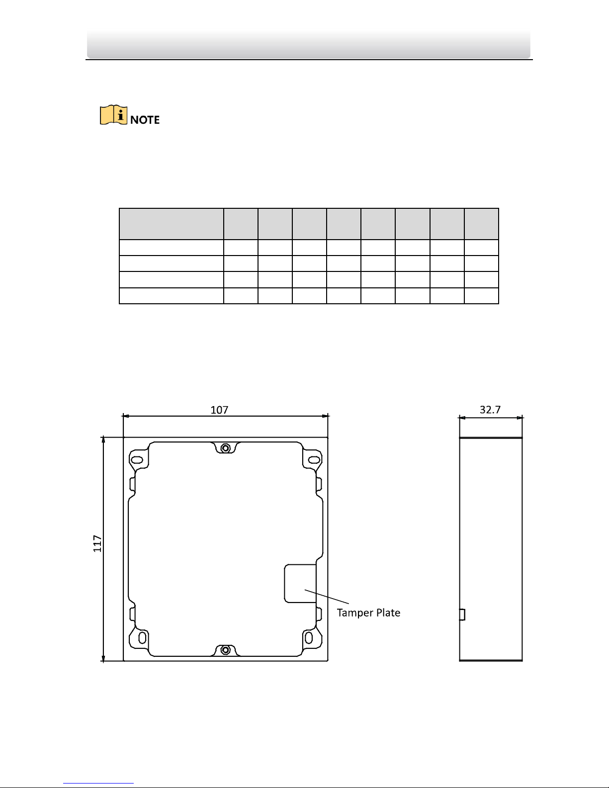
4.2.1 Installation Accessory Description
Figure 4-2 Front and Side View
Page 24
Video Intercom Module Door Station·User Manual
The dimension of one module mounting frame is: 117(L)×107(W)×32.7(D) mm.
The dimensions above are for reference only. The actual size can be slightly different
from the theoretical dimension.
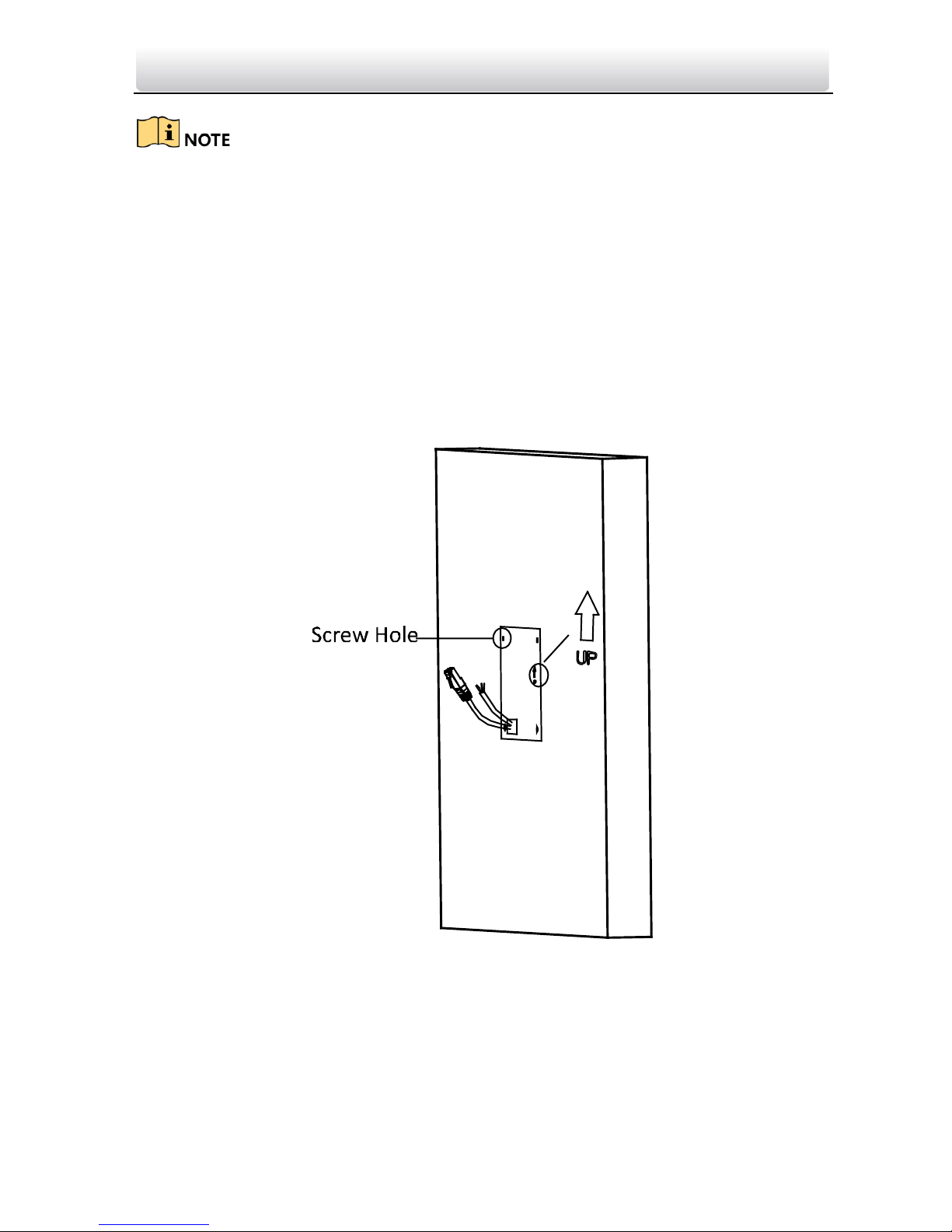
4.2.2 One-Module Surface Mounting
Steps:
1. Paste the installation Sticker 1 onto the wall. Make sure the sticker is placed leveled
via measuring with the gradienter.
2. Chisel 4 holes with drill align to the screw holes on the sticker.
The suggested size of hole is 6 (diameter) × 25 (depth) mm.
The suggested length of cables left outside is 100 mm.
Figure 4-3 Chisel Screw Hole
3. Remove the sticker and insert the expansion sleeves into the screw holes.
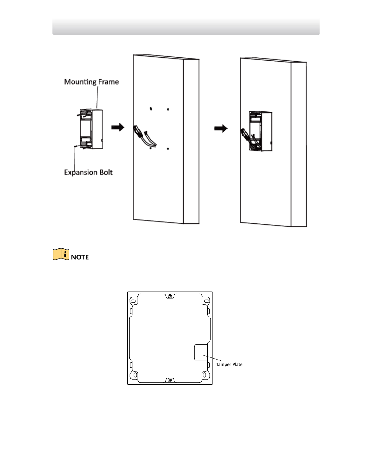
4. Fix the mounting frame onto the wall with 4 expansion bolts.
Page 25
Video Intercom Module Door Station·User Manual
Figure 4-4 Fix the Mounting Frame
The mounting frame should be placed exactly as below for this step. The tamper plate
should be at the low-right.
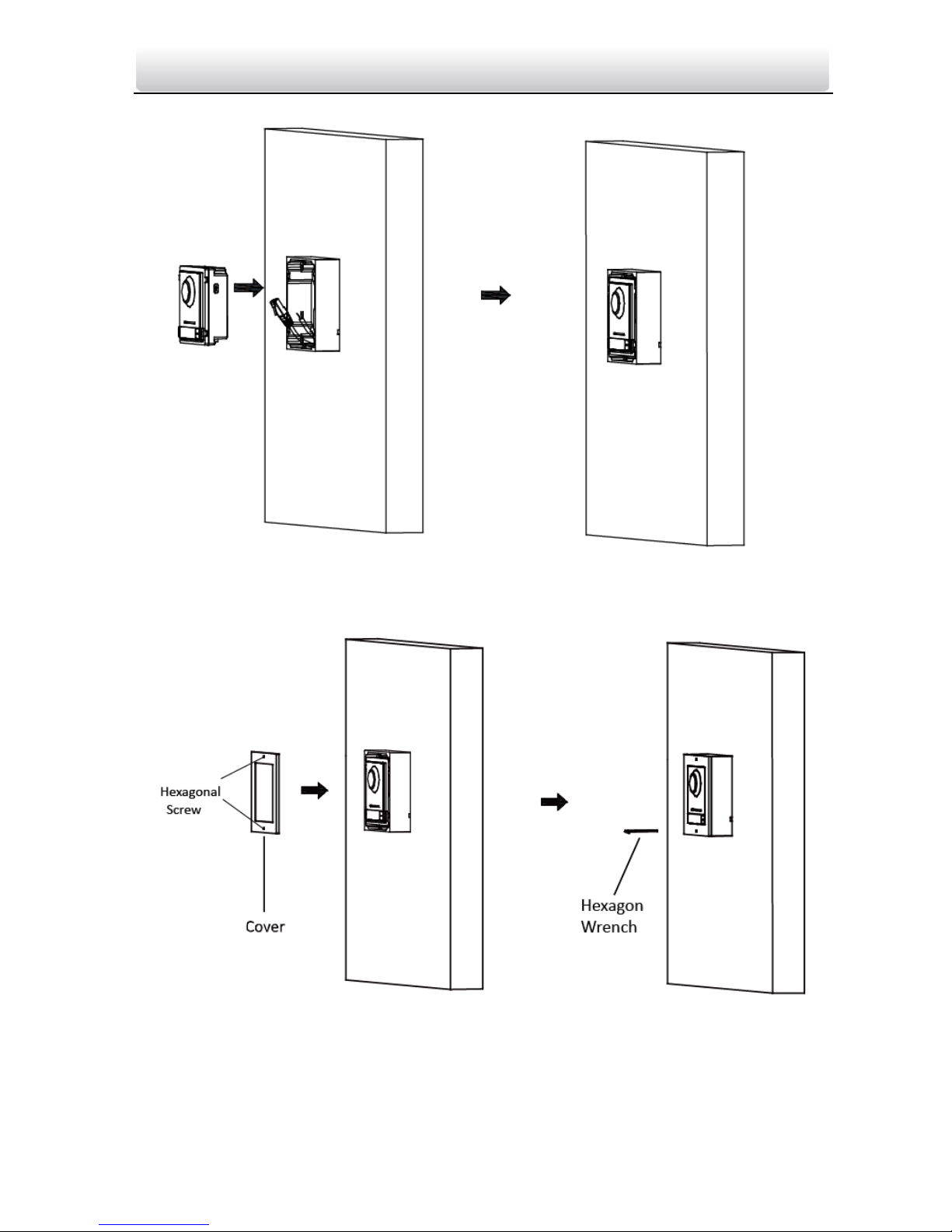
5. Connect the cables to the corresponding interfaces of the main unit and insert it into
the frame.
Page 26
Video Intercom Module Door Station·User Manual
Figure 4-5 Insert the Main unit
6. Use the hexagon wrench in the package fix the cover onto the frame.
Figure 4-6 Fix the Cover
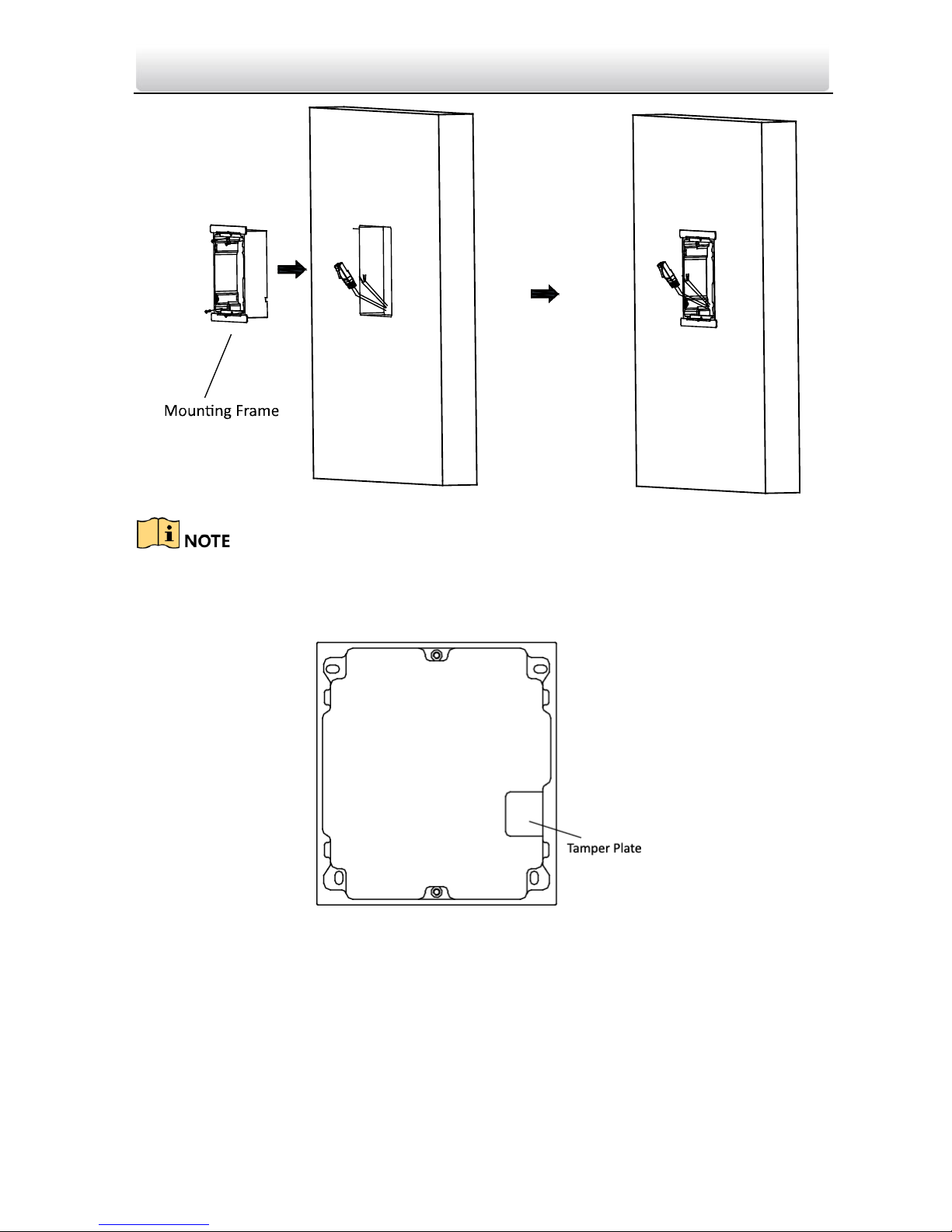
4.2.3 One-Module Flush Mounting
Steps:
Page 27

Video Intercom Module Door Station·User Manual
1. Paste the installation Sticker A onto the wall. Make sure the sticker is placed leveled
via measuring with the gradienter.
2. Cave the installation hole along the solid line on Sticker A.
The suggested dimension of installation hole is 121(L)×111(W)×33(D) mm.
Figure 4-7 Cave the Installation Hole
3. Pull out the cables, place Sticker 1 into the hole, chisel 4 screw holes accordingly.
The suggested size of screw hole is 6 (diameter) × 25 (depth) mm.
The suggested length of cables left outside is 100 mm.
4. Remove the sticker and insert the expansion sleeves into the screw holes.
5. Fix the locating plates to the frame with screws.
Figure 4-8 Install Locating Plate
6. Insert the mounting frame together with the locating plates into the hole, and fix it
with 4 expansion bolts.
Page 28
Video Intercom Module Door Station·User Manual
Figure 4-9 Install Mounting Frame
The mounting frame should be placed exactly as below for this step. The tamper plate
should be at the low-right.
7. Fill and level up the gap between the frame and wall with concrete. Remove the
locating plates after concrete is dry.
8. Connect the cables to the corresponding interfaces of the main unit and insert it into
the frame.
Page 29

Video Intercom Module Door Station·User Manual
Figure 4-10 Insert the Main unit
9. Use the hexagon wrench in the package fix the cover onto the frame.
Figure 4-11 Fix the Cover
Page 30

Video Intercom Module Door Station·User Manual
4.3 Two-Module Installation
4.3.1 Installation Accessory Description
Figure 4-12 Front and Side View
The dimension of two-module mounting frame is: 219(L)×107 (W)×32.7(D) mm.
The dimensions above are for reference only. The actual size can be slightly different
from the theoretical dimension.
4.3.2 Two-Module Surface Mounting
Steps:
1. Paste the installation Sticker 1 onto the wall. Make sure the sticker is placed leveled
via measuring with the gradienter.
2. Chisel 4 holes with drill align to the screw holes on the sticker.
The suggested size of hole is 6 (diameter) × 25 (depth) mm.
The suggested length of cables left outside is 270 mm.
Page 31

Video Intercom Module Door Station·User Manual
Figure 4-13 Chisel Screw Hole
3. Remove the sticker and insert the expansion sleeves into the screw holes.
4. Fix the mounting frame onto the wall with 4 expansion bolts.
Figure 4-14 Fix the Mounting Frame
Page 32

Video Intercom Module Door Station·User Manual
The mounting frame should be placed exactly as below for this step. The tamper plate
should be at the low right of the first grid.
5. Thread the module-connecting line across the thread hole of the frame.
Pass the main unit connecting lines across the thread hole to the upper grid.
Figure 4-15 Placement of Lines
6. Connect the cables and module-connecting line to the corresponding interfaces of the
main unit, then place the main unit into the upper grid.
Connect the other end of the module-connecting line to the input interface of the
sub module.
Organize the line with cable tie in the package. The suggested line connection picture
as below.
Page 33

Video Intercom Module Door Station·User Manual
Figure 4-16 Line Connection Effect Picture
7. Insert the modules in to the frame after wiring. Main unit must be placed in the top
grid.
Figure 4-17 Insert the Modules
8. Use the hexagon wrench in the package fix the cover onto the frame.
Page 34

Video Intercom Module Door Station·User Manual
Figure 4-18 Fix the Cover
4.3.3 Two-Module Flush Mounting
Steps:
1. Paste the installation Sticker A onto the wall. Make sure the sticker is placed leveled
via measuring with the gradienter.
2. Cave the installation hole along the solid line on Sticker A.
The suggested dimension of installation hole is 223(L)×111(W)×33(D) mm.
Figure 4-19 Cave the Installation Hole
3. Pull out the cables, place the installation Sticker 1 into the hole, chisel 4 screw holes
accordingly.
Page 35

Video Intercom Module Door Station·User Manual
The suggested size of screw hole is 6 (diameter) × 25 (depth) mm.
The suggested length of cables left outside is 270 mm.
4. Remove the sticker and insert the expansion sleeves into the screw holes.
5. Fix the locating plates to the frame with screws.
Figure 4-20 Install Locating Plate
6. Insert the mounting frame together with the locating plates into the hole, and fix it
with 4 expansion bolts.
Figure 4-21 Install Mounting Frame
The mounting frame should be placed exactly as below for this step. The tamper plate
should be at the low right of the first grid.
Page 36

Video Intercom Module Door Station·User Manual
7. Fill and level up the gap between the frame and wall with concrete. Remove the
locating plates after the concrete is dry.
8. Thread the module-connecting line across the thread hole of the frame.
Pass the main unit connecting lines across the thread hole to the upper grid.
Figure 4-22 Placement of Lines
9. Connect the cables and module-connecting line to the corresponding interfaces of the
main unit, then place the main unit into the upper grid.
Connect the other end of the module-connecting line to the input interface of the
sub module.
Page 37

Video Intercom Module Door Station·User Manual
Organize the line with cable tie in the package. The suggested line connection picture
as below.
Figure 4-23 Line Connection Effect Picture
10. Insert the modules in to the frame after wiring. Main unit must be placed in the top
grid.
Figure 4-24 Insert the Modules
11. Use the hexagon wrench in the package fix the cover onto the frame.
Page 38

Video Intercom Module Door Station·User Manual
Figure 4-25 Fix the Cover
4.4 Three-Module Installation
4.4.1 Installation Accessory Description
Figure 4-26 Front and Side View
Page 39

Video Intercom Module Door Station·User Manual
The dimension of two-module mounting frame is: 320.8(L)×107 (W)×32.7(D) mm.
The dimensions above are for reference only. The actual size can be slightly different
from the theoretical dimension.
4.4.2 Three-Module Surface Mounting
Steps:
1. Paste the installation Sticker 1 onto the wall. Make sure the sticker is placed leveled
via measuring with the gradienter.
2. Chisel 4 holes with drill align to the screw holes on the sticker.
The suggested size of hole is 6 (diameter) × 25 (depth) mm.
The suggested length of cables left outside is 270 mm.
Figure 4-27 Chisel Screw Hole
3. Remove the sticker and insert the expansion sleeves into the screw holes.
4. Fix the mounting frame onto the wall with 4 expansion bolts.
Page 40

Video Intercom Module Door Station·User Manual
Figure 4-28 Fix the Mounting Frame
The mounting frame should be placed exactly as below for this step. The tamper plate
should be at the low right of the first grid.
5. Thread the module-connecting lines across the thread holes of the frame.
Pass the main unit connecting lines across the thread hole to the top grid.
Page 41

Video Intercom Module Door Station·User Manual
Figure 4-29 Placement of Lines
6. Connect the cables and module-connecting line 1 to the corresponding interfaces of
the main unit, then place the main unit into the upper grid.
Connect the other end of the module-connecting line1 to the input interface of the
sub module. Connect two sub modules via module-connecting line 2.
Organize the line with cable tie in the package. The suggested line connection picture
as below.
Page 42

Video Intercom Module Door Station·User Manual
Figure 4-30 Line Connection Effect Picture
7. Insert the modules in to the frame after wiring. Main unit must be placed in the top
grid.
Figure 4-31 Insert the Modules
8. Use the hexagon wrench in the package fix the cover onto the frame.
Page 43

Video Intercom Module Door Station·User Manual
Figure 4-32 Fix the Cover
4.4.3 Three-Module Flush Mounting
Steps:
1. Paste the installation Sticker A onto the wall. Make sure the sticker is placed leveled
via measuring with the gradienter.
2. Cave the installation hole along the solid line on Sticker A.
The suggested dimension of installation hole is 323(L)×111(W)×33(D) mm.
Figure 4-33 Cave the Installation Hole
Page 44

Video Intercom Module Door Station·User Manual
3. Pull out the cables, place the installation Sticker 1 into the hole, chisel 4 screw holes
accordingly.
The suggested size of screw hole is 6 (diameter) × 25 (depth) mm.
The suggested length of cables left outside is 270 mm.
4. Remove the sticker and insert the expansion sleeves into the screw holes.
5. Fix the locating plates to the frame with screws.
Figure 4-34 Install Locating Plate
6. Insert the mounting frame together with the locating plates into the hole, and fix it
with 4 expansion bolts.
Figure 4-35 Install Mounting Frame
The mounting frame should be placed exactly as below for this step. The tamper plate
should be at the low right of the first grid.
Page 45

Video Intercom Module Door Station·User Manual
7. Fill and level up the gap between the frame and wall with concrete. Remove the
locating plates after the concrete is try.
8. Thread the module-connecting lines across the thread holes of the frame.
Pass the main unit connecting lines across the thread hole to the upper grid.
Page 46

Video Intercom Module Door Station·User Manual
Figure 4-36 Placement of Lines
9. Connect the cables and module-connecting line 1 to the corresponding interfaces of
the main unit, then place the main unit into the upper grid.
Connect the other end of the module-connecting line1 to the input interface of the
sub module. Connect two sub modules via module-connecting line 2.
Organize the line with cable tie in the package. The suggested line connection picture
as below.
Page 47

Video Intercom Module Door Station·User Manual
Figure 4-37 Line Connection Effect Picture
10. Insert the modules in to the frame after wiring. Main unit must be placed in the top
grid.
Figure 4-38 Insert the Modules
11. Use the hexagon wrench in the package fix the cover onto the frame.
Page 48

Video Intercom Module Door Station·User Manual
Figure 4-39 Fix the Cover
Page 49

Video Intercom Module Door Station·User Manual
4.5 More-than-Three Module Installation
4.5.1 Installation Accessory Description
Figure 4-40 Front and Side View
It takes two three-module mounting frames. The dimension of three-module
mounting frame is: 320.8(L)×107 (W)×32.7(D) mm.
The dimensions above are for reference only. The actual size can be slightly different
from the theoretical dimension.
4.5.2 More-than-Three Module Surface Mounting
Steps:
1. Paste two Sticker 1 onto the wall. Make sure the stickers are placed leveled via
measuring with the gradienter.
2. Chisel 8 holes with drill align to the screw holes on the sticker.
The suggested size of hole is 6 (diameter) × 25 (depth) mm.
Page 50

Video Intercom Module Door Station·User Manual
The suggested length of cables left outside is 270 mm.
3. Pull out the cable through the cable hole of the left sticker.
Figure 4-41 Chisel Screw Hole
4. Remove the stickers and insert the expansion sleeves into the screw holes.
5. Thread the module-connecting line (400 mm) and grounding line across the thread
hole of both frames.
Figure 4-42 Place the Grounding Line and Module-Connecting Line
Page 51

Video Intercom Module Door Station·User Manual
There are 6 module-connecting lines in the package: 190 mm *4 and 400 mm*2.
Take the 400 mm one for this step.
The green-yellow line in the package is for grounding.
6. Fix the mounting frame onto the wall with 8 expansion bolts.
Figure 4-43 Fix the Mounting Frame
The mounting frame should be placed exactly as below for this step. The tamper plate
should be at the low right of the first grid.
Page 52

Video Intercom Module Door Station·User Manual
7. Pass the main unit connecting lines across the thread hole to the top grid of the left
frame.
Thread the module-connecting line (190 mm) across the thread hole of the frame.
The lines should be placed as below:
Page 53

Video Intercom Module Door Station·User Manual
Figure 4-44 Placement of Lines
8. Connect the cables and module-connecting line 1 to the corresponding interfaces of
the main unit, then place the main unit into the upper grid.
Connect the other end of the module-connecting line1 to the input interface of the
sub module. Connect all sub modules via module-connecting lines.
Organize the line with cable tie in the package. The suggested line connection picture
as below.
Figure 4-45 Line Connection Effect Picture
9. Insert the modules in to the frame after wiring. Main unit must be placed in the top
grid on the left.
Page 54

Video Intercom Module Door Station·User Manual
Figure 4-46 Insert the Modules
10. Pull the grounding line out and fixed its two end to the screw on the cover.
Figure 4-47 Connect the Grounding Line to the Cover
11. Use the hexagon wrench in the package fix the cover onto the frame.
Page 55

Video Intercom Module Door Station·User Manual
Figure 4-48 Fix the Cover
4.5.3 More-than-Four Module Flush Mounting
Steps:
1. Paste two installation Sticker A onto the wall, align them along the solid line.
Make sure the stickers are placed leveled via measuring with the gradienter.
2. Cave one installation hole along the solid line on the sticker.
The suggested dimension of installation hole is 325(L)×235(W)×33(D) mm..
Page 56

Video Intercom Module Door Station·User Manual
Figure 4-49 Cave the Installation Hole
3. Paste two Sticker 1 inside the installation hole. The gap between two stickers should
be 17 mm. Chisel screw holes according to the stickers.
The suggested size of hole is 6 (diameter) × 25 (depth) mm.
Page 57

Video Intercom Module Door Station·User Manual
Figure 4-50 Chisel Screw Hole
4. Pull out the cable through the cable hole of the left sticker.
The suggested length of cables left outside is 270 mm.
5. Remove the stickers and insert the expansion sleeves into the screw holes.
6. Fix the locating plates to both frames with screws.
Page 58

Video Intercom Module Door Station·User Manual
Figure 4-51 Install Locating Plate
7. Thread the module-connecting line (400 mm) and grounding line across the thread
hole of both frames.
Figure 4-52 Place the Grounding Line and Module-Connecting Line
There are 6 module-connecting lines in the package: 190 mm *4 and 400 mm*2.
Take the 400 mm one for this step.
The green-yellow line in the package is for grounding.
8. Insert the mounting frame together with the locating plates into the hole, and fix it
with 8 expansion bolts.
Page 59

Video Intercom Module Door Station·User Manual
Figure 4-53 Install Mounting Frames
The mounting frame should be placed exactly as below for this step. The tamper plate
should be at the low right of the first grid.
Page 60

Video Intercom Module Door Station·User Manual
9. Fill and level up the gap between the frame and wall with concrete. Remove the
locating plates after the concrete is dry.
10. Pass the main unit connecting lines across the thread hole to the top grid of the left
frame.
Thread the module-connecting line across the thread hole of the frame.
The lines should be placed as below:
Figure 4-54 Placement of Lines
11. Connect the cables and module-connecting line 1 to the corresponding interfaces of
the main unit, then place the main unit into the upper grid.
Connect the other end of the module-connecting line1 to the input interface of the
sub module. Connect all sub modules via module-connecting lines.
Organize the line with cable tie in the package. The suggested line connection picture
as below.
Page 61

Video Intercom Module Door Station·User Manual
Figure 4-55 Line Connection Effect Picture
12. Insert the modules in to the frame after wiring. Main unit must be placed in the top
grid on the left.
Page 62

Video Intercom Module Door Station·User Manual
Figure 4-56 Insert the Modules
13. Pull the grounding line out and fixed its two end to the screw on the cover.
Figure 4-57 Connect the Grounding Line to the Cover
14. Use the hexagon wrench in the package fix the cover onto the frame.
Page 63

Video Intercom Module Door Station·User Manual
Figure 4-58 Fix the Cover
Page 64

Video Intercom Module Door Station·User Manual
5 Device Configuration
You need to activate device and configure corresponding parameters via iVMS-4200
before use.
5.1 Activate Device
You cannot use the door station until you activate it.
You can configure and operate the video intercom devices via iVMS-4200.
Default parameters of door station are as follows:
Default IP Address: 192.0.0.65.
Default Port No.: 8000.
Default User Name: admin.
Steps:
1. Run iVMS-4200, enter Device Management, check the Online Device area.
2. Select an inactivated device and click the Activate button.
3. Create a password, and confirm the password.
Page 65

Video Intercom Module Door Station·User Manual
STRONG PASSWORD RECOMMENDED– We highly recommend you create a
strong password of your own choosing (Using a minimum of 8
characters, including at least three of the following categories:
upper case letters, lower case letters, numbers, and special
characters.) in order to increase the security of your product. And
we recommend you reset your password regularly, especially in the
high security system, resetting the password monthly or weekly can better
protect your product.
4. Click the OK button to activate the device.
When the device is not activated, the basic operation and remote operation of
device cannot be performed.
You can hold the Ctrl or Shift key to select multiple devices in the online devices, and
click the Activate button to activate devices in batch.
5.2 Edit Network Parameters
Purpose:
To operate and configure the device via LAN (Local Area Network), you need connect the
device in the same subnet with your PC. You can edit network parameters via iVMS-4200
software.
Steps:
1. Select an online activated device and click the Modify Netinfo button.
2. Change the device IP address and gateway address to the same subnet with your
computer.
3. Enter the password and click the OK button to activate the network parameters
modification.
Page 66

Video Intercom Module Door Station·User Manual
The default port No. is 8000.
The default IP address of the door station is 192.0.0.65.
After editing the network parameters of device, you should add the devices to the
device list again.
5.3 Add Device
You can add at most 16 door stations to the iVMS-4200.
For the device, you are required to create the password to activate them before they
can be added to the software and work properly.
You can add online devices, and add them manually. Here take adding online video
intercom devices as example.
Steps:
1. Click the icon on the control panel, or click Tools->Device Management to
open the Device Management page.
2. Click Device.
3. On the Device Type panel on the right, you can select Hikvision Device to add video
intercom devices.
4. The active online devices in the same local subnet with the client software will be
displayed on the Online Device area. You can click Refresh Every 60s to refresh the
information of the online devices.
Page 67

Video Intercom Module Door Station·User Manual
To add online devices to the software, you are required to change the device IP
address to the same subnet with your computer first.
5. Select the devices to be added from the list.
6. Click Add to Client to open the device adding dialog box.
7. Input the required information.
Nickname: Edit a name for the device as you want.
Address: Input the device’s IP address. The IP address of the device is obtained
automatically in this adding mode.
Port: Input the device port No. The default value is 8000.
User Name: Input the device user name. By default, the user name is admin.
Password: Input the device password. By default, the password is 12345.
Optionally, you can check the checkbox Export to Group to create a group by the
device name. All the channels of the device will be imported to the corresponding
group by default.
iVMS-4200 also provides a method to add the offline devices. Check the checkbox
Add Offline Device, input the required information and the device channel number
and alarm input number, and then click Add. When the offline device comes online,
the software will connect it automatically.
8. Click Add to add the device.
Page 68

Video Intercom Module Door Station·User Manual
Add Multiple Online Devices
If you want to add multiple online devices to the client software, click and hold Ctrl key
to select multiple devices, and click Add to Client to open the device adding dialog box.
In the pop-up message box, enter the user name and password for the devices to be
added.
Add All the Online Devices
If you want to add all the online devices to the client software, click Add All and click OK
in the pop-up message box. Then enter the user name and password for the devices to
be added.
5.4 Reset Password
You can restore the default password or resetting the password for the door station.
Select the device from the online device list, click Reset Password.
If the window with import file button, key importing mode drop-down list, password
and confirm password field pops up, follow the steps below to reset the password:
This option is available to door stations.
Page 69

Video Intercom Module Door Station·User Manual
1. Click Export to save the device file on your computer.
2. Send the file to our technical engineers.
3. Our technical engineer will send you a file to you. After receiving a file from the
technical engineer, select Import File from Key Importing Mode drop-down list and
click to import the file.
4. Input new password in text fields of Password and Confirm Password.
5. Click OK to reset the password.
STRONG PASSWORD RECOMMENDED– We highly recommend you create a strong
password of your own choosing (Using a minimum of 8 characters,
including at least three of the following categories: upper case letters,
lower case letters, numbers, and special characters.) in order to
increase the security of your product. And we recommend you reset
your password regularly, especially in the high security system,
resetting the password monthly or weekly can better protect your product.
Page 70

Video Intercom Module Door Station·User Manual
5.5 Configure System Parameters
In the device list area, select a device and click or to enter
the remote configuration interface.
Click the System button on the remote configuration interface to display the device
information: Device Information, General, Time, System Maintenance, User, and so on.
5.5.1 Device Information
Click the Device Information button to enter device basic information interface. You can
view basic information (the device type, and serial No.), and version information of the
device.
5.5.2 General
Click the General button to enter device general parameters settings interface. You can
view and edit the device name and device ID.
5.5.3 Time
Steps:
Page 71

Video Intercom Module Door Station·User Manual
1. Click the Time button to enter the device time settings interface.
2. Select Time Zone or Enable NTP.
Time Zone
1) Select a time zone from the drop-down list menu.
2) Click the Synchronization button.
NTP
1) Check the checkbox of Enable NTP to enable NTP.
2) Enter the server address, NTP port, and synchronization interval.
DST
1) Check the checkbox of Enable DST to enable DST.
2) Enter the start time and end time of DST, and set the DST bias.
3. Click the Save button to save and realize the time settings.
The default port No. is 123.
5.5.4 System Maintenance
Purpose:
You can operate the system management and remote upgrading on the system
maintenance interface.
Steps:
1. Click the System Maintenance button to enter the system maintenance interface.
Page 72

Video Intercom Module Door Station·User Manual
2. Click Reboot and the system reboot dialog box pops up. Click Yes to reboot the
system.
3. Click Restore Default Settings to restore the default parameters.
4. Click Restore All to restore all parameters of device and reset the device to inactive
status.
5. Click Import Configuration File and the import file window pops up. Select the path
of remote configuration files. Click Open to import the remote configuration file. The
configuration file is imported and the device will reboot automatically.
6. Click Export Configuration File and the export file window pops up. Select the saving
path of remote configuration files and click Save to export the configuration file.
Page 73

Video Intercom Module Door Station·User Manual
7. Click to select the upgrade file and click Upgrade to remote upgrade the device.
The process of remote upgrade will be displayed in the process bar.
Figure 5-1 Remote Upgrade
Click Restore Default Settings button, all default settings, excluding network
parameters, will be restored.
Click Restore All button, all default settings, including network parameters, will be
restored. The device will be reset to inactivated status.
5.5.5 User
Purpose:
You can edit the password for logging in the device.
Steps:
1. Click the User button to enter the user information editing interface.
2. Select the user to edit and click the Modify button to enter the user parameter
interface.
Page 74

Video Intercom Module Door Station·User Manual
3. Enter the new password, and confirm it.
4. Click the Save button to realize the editing of password.
The new password and confirm password should be identical.
After editing the password of device, click button from the device list, the added
device will not be there. You should add the device again with new password to
operate the remote configuration.
5.6 Configure Video Intercom Parameters
Click the Video Intercom button on the remote configuration interface to enter the
video intercom parameters settings: Device Number Configuration, Time Parameters,
Access and Elevator Control, IO Input/Output, Volume, Dial, Sub Module and so on.
5.6.1 Device ID Configuration
Steps:
1. Click the ID Configuration button to enter device ID configuration interface.
Page 75

Video Intercom Module Door Station·User Manual
2. Select the device type from the drop-down list, and set the corresponding
information.
3. Click the Save button to enable the device number configuration.
For main door station, the serial No. is 0.
For sub door station, the serial No. is higher than 0. Serial No. ranges from 1 to 99.
For each villa or building, at least one main door station should be configured, and
sub door stations can be customized.
For one main door station, at most 8 sub door stations can be customized.
5.6.2 Time Parameters
1. Click the Time Parameters button to enter time parameters settings interface.
2. Configure the maximum ring duration, maximum live view time, and call forwarding
time.
3. Click the Save button.
For door station, maximum speaking time and maximum message time should be
configured. Maximum speaking time varies from 90s to 120s, and maximum message
time varies from 30s to 60s.
5.6.3 Access Control and Elevator
Click Access Control and Elevator to enter corresponding configuration page.
Page 76

Video Intercom Module Door Station·User Manual
Access Control
1. Select the door No..
2. Set the door-unlocked duration.
3. (Optional) Enable Upload Alarm for Not-Closed Door.
4. Click Save to enable the settings.
The door-unlocked duration ranges from 1s to 225s.
If you check Upload Alarm for Not-Closed Door, an alarm will be triggered
automatically if the door is not locked in the configured duration.
Enabling Card Encrypt, the door station can recognize the encrypted information of
the card when you swiping the card on the door station.
Elevator Control
Before you start
Page 77

Video Intercom Module Door Station·User Manual
Make sure your door station is in the mode of main door station. Only the main door
station support elevator control function.
Connection between the door station and the elevator controller supports
network interface.
Step:
1. Select an elevator No., and select an elevator controller type for the elevator.
2. Set the negative floor.
3. Select the interface type: network Interface, enter the elevator controller’s IP address,
port No., user name, and password.
4. Enable the elevator control.
Up to 4 elevator controllers can be connected to one door station.
Up to 10 negative floors can be added.
Make sure the interface types of elevator controllers, which are connected to the
same door station, are consistent.
5.6.4 IO Input and Output
Step:
1. Click the I/O Input and Output button to enter the I/O input and output interface.
2. Select I/O input No., input mode, output No., and output mode.
3. Click the Save button to enable the settings.
For door station, there are 4 I/O Input Terminals. By default, Terminal 1and 2
correspond to Door Status. Terminal 3 and 4 correspond to interfaces of Door
Switch.
Page 78

Video Intercom Module Door Station·User Manual
For door station, there are 2 I/O Output Terminals. Terminal 1~2 correspond to
DOOR interfaces (NO1/COM/NC1; NO2/COM/NC2) of door station. Door 1 is enabled
by default. You can enable/disable IO Out according to needs.
5.6.5 Volume Input and Output
Step:
1. Click Volume Input/Output button to enter the volume input and output interface.
2. Slide the slider to adjust the volume input and volume output.
3. Click the Save button to enable the settings.
5.6.6 Dial
Step:
1. Click Dial button to enter the dial interface.
2. Enter the room No. of the indoor station that the door station connected to.
3. Click the Save button to enable the settings.
By default, quick press the call button, the door station calls resident. If you check
Quick Press for Calling Center, the door station calls the management center when
quick press the call button of the main unit.
5.6.7 Sub Module
Step:
1. Click Sub Module button to enter the sub module configuration interface.
Page 79

Video Intercom Module Door Station·User Manual
2. Click to pop up the configuration interface.
3. Enter the room no. for each call button of the nametag module.
4. Click the Save button to enable the settings.
The module address is used to differentiate the sub modules. See 4.1Configure Sub
Module Address for detailed configuration instructions.
5.7 Configure Video Intercom Network
You need to configure video intercom network parameters in the network module.
Click Network in the remote configuration interface, to configure the local network,
linked network and FTP settings.
5.7.1 Local Network Configuration
Steps:
1. Click the Local Network Configuration button to enter local network configuration
interface.
Page 80

Video Intercom Module Door Station·User Manual
2. Enter the local IP address, subnet mask, gateway address, and port No..
3. Click the Save button to enable the settings.
The default port No. is 8000.
After editing the local network parameters of device, you should add the devices to
the device list again.
5.7.2 Linked Devices Network Configuration
Purpose:
In the linked devices network configuration interface, you can configure the network
parameters of master stations, SIP servers and management centers of the same LAN.
The devices can be linked to the door station and realize the linkage between these
devices.
Steps:
1. Click the Linked Network Configuration button to enter linked network configuration
interface.
2. Enter the master station IP address, (main) door station IP address, SIP server IP
address, management center IP address.
3. Select the main door station type from the drop-down list.
4. Click the Save button to enable the settings.
After adding master station IP Address, the linkage between indoor station and
master station can be realized.
After adding the door station IP Address, the video intercom between indoor
stations of same building can be realized.
Page 81

Video Intercom Module Door Station·User Manual
After adding SIP Server Address IP, the video intercom of same community: video
intercom between indoor stations of different building, calling indoor station from
outer door station and video intercom between management center and indoors.
After adding management center IP Address, the events can be uploaded to the
management center.
For indoor extension, only parameter about the main indoor station should be
configured.
5.7.3 FTP
After configuring the FTP parameters, the captured pictures of door station will be
uploaded to the FTP server automatically.
Steps:
1. Click the FTP button to enter the FTP parameters interface.
2. Check the checkbox of Enable Main FTP.
3. Select IP address from the drop-down list of server mode.
4. Enter the FTP server address, and port No..
5. Check the checkbox to enable the anonymity (optional).
6. Enter the name and password.
Page 82

Video Intercom Module Door Station·User Manual
7. Select the directory structure and set the separator, naming item, and naming
element.
8. Click the Save button to enable the FTP parameters settings.
The default port No. is 21.
To enable anonymity or not is according to whether the FTP server enables
anonymity.
5.7.4 Advanced Settings
Steps:
1. Click the Advanced Settings button to enter the advanced network settings interface.
2. Enter the DNS server addresses.
3. Click the Save button to enable the advanced network settings.
5.8 Video Display
5.8.1 Video Parameters
Steps:
1. Click the Video Parameters button to enter the video parameters interface.
Page 83

Video Intercom Module Door Station·User Manual
2. Select the camera No..
3. Select the video standard (PAL and NTSC can be selected).
4. Set WDR mode (Disable or Enable).
5. Set the brightness, contrast, saturation and sharpness of the video.
6. Click the Save button to enable the settings.
Click the Restore Default Settings button to restore all video parameters excluding
network parameters to the factory settings.
5.8.2 Video & Audio
Steps:
1. Click the Video & Audio button to enter the video parameters settings interface.
Page 84

Video Intercom Module Door Station·User Manual
2. Set the parameters accordingly.
3. Click the Save button to enable the settings.
It’s suggested to keep the default settings to ensure the video/image quality.
Page 85

Video Intercom Module Door Station·User Manual
6 Video Intercom Operation
6.1 Video Intercom Operation via Device
You can call corresponding resident by pressing the call button on the main unit or on
the nametag unit.
Make sure you have configured the room No. for the device.
6.2 Video Intercom Operation via iVMS-4200
Purpose:
The Video Intercom Management module provides the function of video intercom,
checking call logs and managing notice via the iVMS-4200 client software.
For the user with access control module permissions, the user can enter the Access
Control module and manage video intercom and search information.
Before you start:
Before you can remote control the video intercom, you should add the device to the
software and configure the person to link the device in the Access Control module.
Click -> tab on the left icon bar to enter the Video Intercom interface.
6.2.1 Receive Call from Door Station
Steps:
1. Select the client software in door station interface to start calling the iVMS-4200
and an incoming call dialog will pop up in the client software.
Page 86

Video Intercom Module Door Station·User Manual
2. Click Answer to answer the call.
Or click Hang Up to decline the call.
3. After you answer the call, you will enter the In Call window.
Click to adjust the volume of the loudspeaker.
Click to hang up.
Page 87

Video Intercom Module Door Station·User Manual
Click to adjust the volume of the microphone.
For door station, you can click to open the door remotely.
One video intercom device can only connect with one client software.
The maximum ring duration can be set from 15s to 60s via the Remote
Configuration of the video intercom device.
The maximum speaking duration between indoor station and iVMS-4200 can be
set from 120s to 600s via the Remote Configuration of indoor station.
The maximum speaking duration between door station and iVMS-4200 can be set
from 90s to 120s via the Remote Configuration of door station.
6.2.2 View Live Video of Door Station
You can get the live view of the main unit in the Main View module and control the
door station remotely.
In the Main View module, double-click a door station or drag the device to a display
window to start the live view.
Right click on the live view interface, click the unlock icon to remote unlock the door.
6.2.3 View Call Logs
Purpose:
You can check all the call logs, including dialed call logs, received call logs and missed call
logs. You can also directly dial via the log list and clear the logs.
Steps:
Page 88

Video Intercom Module Door Station·User Manual
1. In the Video Intercom page, click the Call Log tab to enter the Call Log page.
All the call logs will display on this page and you can check the log information, e.g.,
call status, start time, resident’s organization and name, device name and ring or
speaking duration.
2. (Optional) Click the icon in the Operation column to re-dial the resident.
3. (Optional) Click the icon in the Operation column to delete the call log.
Or you can click Clear at the upper right corner to clear all the logs.
6.2.4 Search Video Intercom Information
Purpose:
You can search the call logs between the iVMS-4200 client software and video intercom
devices, device unlocking logs and the sent notice information.
In the Access Control module, click icon tab to open the Search page.
Search Call Logs
Steps:
1. In the Information Search page, click the Call Log to enter the Call Log interface.
Page 89

Video Intercom Module Door Station·User Manual
2. Set the search conditions, including call status, device type, start time and end
time.
Call Status: Click to unfold the drop-down list and select the call status as
Dialed, Received or Missed. Or select All to search logs with all statuses.
Device Type: Click to unfold the drop-down list and select the device
type as Indoor Station, Door Station, Outer Door Station or Analog Indoor
Station. Or select All Devices to search logs with all device types.
Start Time/End Time: Click to specify the start time and end time of a
time period to search the logs.
(Optional) You can click Reset to reset all the configured search conditions.
3. Click Search and all the matched call logs will display on this page.
For the search results,
(Optional) Check the detailed information of searched call logs, such as call
status, ring/speaking duration, device name, resident organization, etc.
(Optional) Input keywords in the Search field to filter the desired log.
(Optional) Click Export to export the call logs to your PC.
Search Unlocking Logs
Steps:
1. In the Information Search page, click Unlocking Log tab to enter the Unlocking Log
interface.
Page 90

Video Intercom Module Door Station·User Manual
2. Set the search conditions, including unlocking type, device type, start time and end
time.
Unlocking Type: Click to unfold the drop-down list and select the
unlocking type as Unlock by Password, Unlock by Duress, Unlock by Card,
Unlock by Resident or Unlock by Center. Or select All to search logs with all
unlocking types.
Device Type: Click to unfold the drop-down list and select the device
type as Door Station or Door Station (V Series). Or select All Devices to
search logs with all device types.
Start Time/End Time: Click to specify the start time and end time of a
time period to search the logs.
3. (Optional) You can click Reset to reset all the configured search conditions.
4. Click Search and all the matched unlocking logs will display on this page.
For the searching results,
(Optional) Check the detailed information of searched unlocking logs, such as
unlocked time, card No., device No., etc.
(Optional) Input keywords in the Search field to filter the searching result.
(Optional) Click in the Capture column to view the captured pictures.
Viewing captured picture should be supported by device.
(Optional) Click Export to export the unlocking logs to your PC.
Page 91

UD11560B
 Loading...