

Page 1

Video Intercom
Vandal-Resistant Door Station
User Manual
UD03854B
Page 2
Series
Model
Vandal-Resistant Door Station
DS-KB8112-IM
Video Intercom Vandal-Resistant Door Station·User Manual
User Manual
© 2017 Hangzhou Hikvision Digital Technology Co., Ltd.
This user manual is intended for users of the models below:
It includes instructions on how to use the Product. The software embodied in the
Product is governed by the user license agreement covering that product.
About this Manual
This Manual is subject to domestic and international copyright protection. Hangzhou
Hikvision Digital Technology Co., Ltd. (“Hikvision”) reserves all rights to this manual. This
manual cannot be reproduced, changed, translated, or distributed, partially or wholly, by
any means, without the prior written permission of Hikvision.
Trademarks
and other Hikvision marks are the property of Hikvision and are
registered trademarks or the subject of applications for the same by Hikvision and/or its
affiliates. Other trademarks mentioned in this manual are the properties of their
respective owners. No right of license is given to use such trademarks without express
permission.
Disclaimer
TO THE MAXIMUM EXTENT PERMITTED BY APPLICABLE LAW, HIKVISION MAKES NO WARRANTIES,
EXPRESS OR IMPLIED, INCLUDING WITHOUT LIMITATION THE IMPLIED WARRANTIES OF
MERCHANTABILITY AND FITNESS FOR A PARTICULAR PURPOSE, REGARDING THIS MANUAL.
HIKVISION DOES NOT WARRANT, GUARANTEE, OR MAKE ANY REPRESENTATIONS REGARDING THE
USE OF THE MANUAL, OR THE CORRECTNESS, ACCURACY, OR RELIABILITY OF INFORMATION
CONTAINED HEREIN. YOUR USE OF THIS MANUAL AND ANY RELIANCE ON THIS MANUAL SHALL BE
WHOLLY AT YOUR OWN RISK AND RESPONSIBILITY.
TO THE MAXIMUM EXTENT PERMITTED BY APPLICABLE LAW, IN NO EVENT WILL HIKVISION, ITS
DIRECTORS, OFFICERS, EMPLOYEES, OR AGENTS BE LIABLE TO YOU FOR ANY SPECIAL,
CONSEQUENTIAL, INCIDENTAL, OR INDIRECT DAMAGES, INCLUDING, AMONG OTHERS, DAMAGES
FOR LOSS OF BUSINESS PROFITS, BUSINESS INTERRUPTION, SECURITY BREACHES, OR LOSS OF DATA
OR DOCUMENTATION, IN CONNECTION WITH THE USE OF OR RELIANCE ON THIS MANUAL, EVEN IF
HIKVISION HAS BEEN ADVISED OF THE POSSIBILITY OF SUCH DAMAGES.
SOME JURISDICTIONS DO NOT ALLOW THE EXCLUSION OR LIMITATION OF LIABILITY OR CERTAIN
DAMAGES, SO SOME OR ALL OF THE ABOVE EXCLUSIONS OR LIMITATIONS MAY NOT APPLY TO YOU.
Support
Should you have any questions, please do not hesitate to contact your local dealer.
i
Page 3
Video Intercom Vandal-Resistant Door Station·User Manual
Regulatory Information
FCC Information
Please take attention that changes or modification not expressly approved by the party
responsible for compliance could void the user’s authority to operate the equipment.
FCC compliance: This equipment has been tested and found to comply with the limits
for a Class B digital device, pursuant to part 15 of the FCC Rules. These limits are
designed to provide reasonable protection against harmful interference in a residential
installation. This equipment generates, uses and can radiate radio frequency energy and,
if not installed and used in accordance with the instructions, may cause harmful
interference to radio communications. However, there is no guarantee that interference
will not occur in a particular installation. If this equipment does cause harmful
interference to radio or television reception, which can be determined by turning the
equipment off and on, the user is encouraged to try to correct the interference by one
or more of the following measures:
—Reorient or relocate the receiving antenna.
—Increase the separation between the equipment and receiver.
—Connect the equipment into an outlet on a circuit different from that to which the
receiver is connected.
—Consult the dealer or an experienced radio/TV technician for help.
FCC Conditions
This device complies with part 15 of the FCC Rules. Operation is subject to the following
two conditions:
1. This device may not cause harmful interference.
2. This device must accept any interference received, including interference that may
cause undesired operation.
EU Conformity Statement
This product and - if applicable - the supplied accessories too are
marked with "CE" and comply therefore with the applicable
harmonized European standards listed under the EMC Directive
2014/30/EU, the RoHS Directive 2011/65/EU.
2012/19/EU (WEEE directive): Products marked with this symbol
cannot be disposed of as unsorted municipal waste in the European
Union. For proper recycling, return this product to your local
supplier upon the purchase of equivalent new equipment, or
dispose of it at designated collection points. For more information
see: www.recyclethis.info
ii
Page 4

Video Intercom Vandal-Resistant Door Station·User Manual
2006/66/EC (battery directive): This product contains a battery that
cannot be disposed of as unsorted municipal waste in the
European Union. See the product documentation for specific
battery information. The battery is marked with this symbol, which
may include lettering to indicate cadmium (Cd), lead (Pb), or
mercury (Hg). For proper recycling, return the battery to your
supplier or to a designated collection point. For more
information see: www.recyclethis.info
Industry Canada ICES-003 Compliance
This device meets the CAN ICES-3 (B)/NMB-3(B) standards requirements.
iii
Page 5

Warnings Follow
these safeguards to
prevent serious
injury or death.
Cautions Follow these
precautions to prevent
potential injury or
material damage.
Video Intercom Vandal-Resistant Door Station·User Manual
Safety Instruction
These instructions are intended to ensure that user can use the product correctly to
avoid danger or property loss.
The precaution measure is divided into Warnings and Cautions:
Warnings: Neglecting any of the warnings may cause serious injury or death.
Cautions: Neglecting any of the cautions may cause injury or equipment damage.
Warnings
All the electronic operation should be strictly compliance with the electrical safety
regulations, fire prevention regulations and other related regulations in your local
region.
Please use the power adapter, which is provided by normal company. The power
consumption cannot be less than the required value.
Do not connect several devices to one power adapter as adapter overload may cause
over-heat or fire hazard.
Please make sure that the power has been disconnected before you wire, install or
dismantle the device.
When the product is installed on wall or ceiling, the device shall be firmly fixed.
If smoke, odors or noise rise from the device, turn off the power at once and unplug
the power cable, and then please contact the service center.
If the product does not work properly, please contact your dealer or the nearest
service center. Never attempt to disassemble the device yourself. (We shall not
assume any responsibility for problems caused by unauthorized repair or
maintenance.)
Cautions
Do not drop the device or subject it to physical shock, and do not expose it to high
electromagnetism radiation. Avoid the equipment installation on vibrations surface or
places subject to shock (ignorance can cause equipment damage).
Do not place the device in extremely hot (refer to the specification of the device for
the detailed operating temperature), cold, dusty or damp locations, and do not
expose it to high electromagnetic radiation.
The device cover for indoor use shall be kept from rain and moisture.
iv
Page 6

Video Intercom Vandal-Resistant Door Station·User Manual
Exposing the equipment to direct sun light, low ventilation or heat source such as
heater or radiator is forbidden (ignorance can cause fire danger).
Do not aim the device at the sun or extra bright places. A blooming or smear may
occur otherwise (which is not a malfunction however), and affecting the endurance of
sensor at the same time.
Please use the provided glove when open up the device cover, avoid direct contact
with the device cover, because the acidic sweat of the fingers may erode the surface
coating of the device cover.
Please use a soft and dry cloth when clean inside and outside surfaces of the device
cover, do not use alkaline detergents.
Please keep all wrappers after unpack them for future use. In case of any failure
occurred, you need to return the device to the factory with the original wrapper.
Transportation without the original wrapper may result in damage on the device and
lead to additional costs.
Improper use or replacement of the battery may result in hazard of explosion.
Replace with the same or equivalent type only. Dispose of used batteries according to
the instructions provided by the battery manufacturer.
v
Page 7

Video Intercom Vandal-Resistant Door Station·User Manual
Table of Contents
1 Overview ...................................................................................................... 1
1.1 Introduction ............................................................................................................. 1
1.2 Main Features .......................................................................................................... 1
1.3 Typical Application ................................................................................................... 3
2 Appearance .................................................................................................. 4
3 Terminals and Wiring ................................................................................... 5
3.1 Terminals and Interfaces Description....................................................................... 5
3.2 Wiring Description ................................................................................................... 5
3.2.1 Door Lock Wiring .............................................................................................. 5
3.2.2 Door Magnetic Wiring ....................................................................................... 6
3.2.3 Exit Button Wiring ............................................................................................. 6
3.2.4 Alarm Device Input Wiring ................................................................................ 7
4 Installation ................................................................................................... 8
4.1 Wall Mounting Plate ................................................................................................ 8
4.2 Wall Mounting ......................................................................................................... 8
5 Activating Door Station .............................................................................. 12
5.1 Activation via Web Browser ................................................................................... 12
5.2 Activation via Batch Configuration Tool ................................................................. 13
5.3 Activation via iVMS-4200 Client Software ............................................................. 14
6 Local Operation .......................................................................................... 16
7 Remote Operation via Web Browser .......................................................... 17
7.1 Access to the Door Station......................................................................................17
7.2 Live View ............................................................................................................... 18
7.2.1 Live View Page ................................................................................................ 18
7.2.2 Starting Live View ........................................................................................... 19
7.2.3 Recording and Capturing Pictures Manually ................................................... 20
7.3 Door Station Configuration .................................................................................... 20
7.3.1 Configuring Local Parameters.......................................................................... 20
7.3.2 Configuring System Settings ............................................................................ 21
7.3.3 Configuring Video Intercom Parameters ......................................................... 28
7.3.4 Configuring Network Settings ......................................................................... 32
7.3.5 Configuring Video/Audio Settings ................................................................... 38
7.3.6 Configuring Image Parameters ........................................................................ 39
7.3.7 Configuring Event Settings .............................................................................. 41
8 Remote Operation via Batch Configuration Tool ......................................... 46
8.1 Editing Network Parameters .................................................................................. 46
8.2 Adding Device ......................................................................................................... 47
vi
Page 8

Video Intercom Vandal-Resistant Door Station·User Manual
8.2.1 Adding Online Device ....................................................................................... 47
8.2.2 Adding by IP Address ....................................................................................... 48
8.2.3 Adding by IP Segment ..................................................................................... 48
8.3 Configuring Devices Remotely ............................................................................... 49
8.3.1 System ............................................................................................................. 49
8.3.2 Video Intercom ............................................................................................... 54
8.3.3 Network ...........................................................................................................62
8.3.4 Video Display ...................................................................................................67
8.4 Video Intercom Device Set-up Tool ....................................................................... 69
8.4.1 Setting a Community Structure ........................................................................70
8.4.2 Setting Main/Sub Door Station ........................................................................70
8.5 Batch Upgrading .................................................................................................... 73
8.5.1 Adding Devices for Upgrading ......................................................................... 73
8.5.2 Upgrading Devices ........................................................................................... 75
9 Remote Operation via iVMS-4200 Client Software ..................................... 77
9.1 System Configuration ............................................................................................. 77
9.2 Device Management ...............................................................................................78
9.2.1 Adding Video Intercom Devices .......................................................................78
9.2.2 Modifying Network Information ..................................................................... 81
9.2.3 Resetting Password ......................................................................................... 81
9.3 Configuring Devices Remotely via iVMS-4200 ....................................................... 83
9.4 Picture Storage ...................................................................................................... 83
9.4.1 Adding Storage Server ..................................................................................... 84
9.4.2 Formatting the HDDs ....................................................................................... 85
9.4.3 Configuring Storage Server Picture Storage .................................................... 85
9.5 Live View ................................................................................................................87
9.6 Video Intercom Configuration ............................................................................... 89
9.6.1 Group Management ........................................................................................ 90
9.6.2 Video Intercom ............................................................................................... 95
9.6.3 Notice Management ....................................................................................... 96
9.7 Device Arming Control ........................................................................................... 98
Appendix .................................................................................................... 100
Installation Notice ..................................................................................................... 100
Wiring Cables ............................................................................................................ 100
vii
Page 9
Video Intercom Vandal-Resistant Door Station·User Manual
1 Overview
1.1 Introduction
The DS-KB8112-IM is a vandal-resistant door station, which has passed IK 9 (Impact
Protection Level). The door station, featuring in the vandal-resistant design, convenient
installation, and easy operation, supports the video intercom function, access control
function, door magnetic alarm, motion detection, and so on. As an intelligent device,
the door station is mainly applied in the villa for improving the living security.
1.2 Main Features
Basic Functions
Video intercom function, supporting the communication with the master station, and
the indoor station
Access control function, supporting multiple door opening modes (the indoor station,
the master station, the client software, and the web)
Self-adaptive IR supplement with max. 5-meter IR distance
High-performance embedded SOC processor
IK 9 and IP 66
Video/Audio Functions
HD video surveillance with WDR wide angle and high performance CMOS, up to 720P
@ 30 fps
1
Page 10

Video Intercom Vandal-Resistant Door Station·User Manual
Noise suppression and echo cancellation
H.264 video compression standard
Low illumination
Alarm Functions
Supports door magnetic alarm
Auto-uploads alarm messages to the master station or the client software
Remote Controls
Remote reboot, remote upgrade, time synchronization via NTP, and batch
configuration function
Supports Web remote access and OSD display
Supports motion detection
Additional Features
ISAPI (Internet Server Application Programming Interface) and ONVIF (Open Network
Video Interface Forum) supported, to ensure greater compatibility and
interoperability among different platforms
Supports bit rate and frame rate configuration, P/N video standard configuration,
Email configuration, and auto day & night switch
Auto-uploads captured pictures to the FTP or the client software while unlocking the
door
2
Page 11
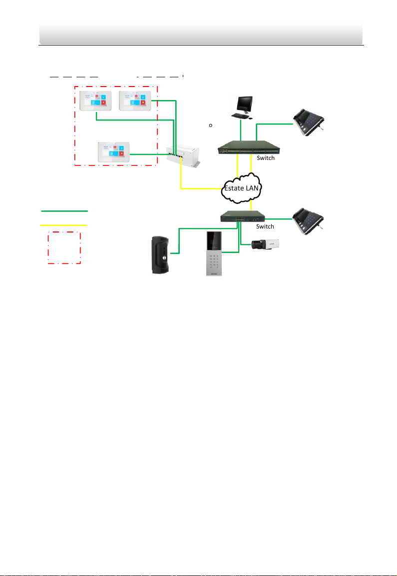
Switch
Client Software
Network Cable
Optical Fiber
Door Station
Resident 1
Indoor Station
IPC
Video/Audio
Distributor
Outer Door Station
Estate LAN
Switch
Indoor
Extension 1
Indoor
Extension 2
One Resident
Center Master Station
(Master Station)
Master Station
in Guard's Room
Video Intercom Vandal-Resistant Door Station·User Manual
1.3 Typical Application
Note:
DS-KB8112-IM door station can work as a doorphone both in a villa or in an apartment.
3
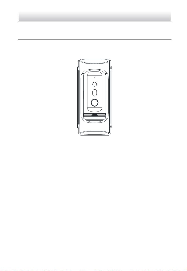
Page 12
1
2
3
5
4
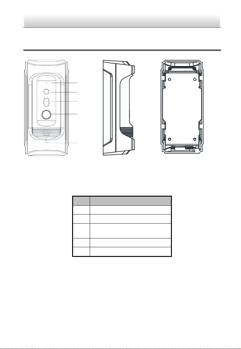
Figure 2-1 Door Station Overview
No.
Description
1
Microphone
2
Built-in Camera
3
Low Illumination Supplement
Light
4
Call Button
5
Loudspeaker
Video Intercom Vandal-Resistant Door Station·User Manual
2 Appearance
Table 2-1 Components Description
Note:
Default settings of call button: when you press the call button, it calls the resident;
and when you hold down the call button, it calls the center.
You can change the calling mode via Batch Configuration Tool or iVMS-4200 client
software or the web browser. See 7.3.3 Configuring Video Intercom Parameters and
8.3.2 Video Intercom for detail steps.
4
Page 13
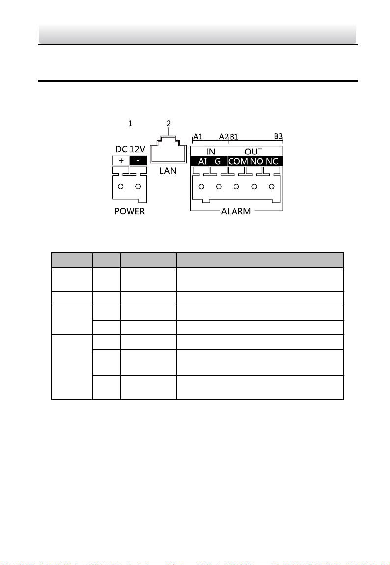
Name
No.
Interfaces
Description
Power
Supply
1
12 VDC
12 VDC Power Supply Input
LAN 2 LAN
Network Interface (PoE Supported)
ALARM
IN
A1
AI
Alarm Input
A2
GND
Grounding
ALARM
OUT
B1
COM
Grounding Signal
B2
NO
Door Lock Relay Output
(Connect Electric Strike)
B3
NC
Door Lock Relay Output (Connect Electric
Bolt or Magnetic Lock)
Video Intercom Vandal-Resistant Door Station·User Manual
3 Terminals and Wiring
3.1 Terminals and Interfaces Description
Figure 3-1 Terminals and Interfaces
Table 3-1 Terminals and Interfaces Description
3.2 Wiring Description
3.2.1 Door Lock Wiring
Terminal NC/COM is set as default for connecting magnetic lock/electric bolt; terminal
NO/ COM is set as default for connecting electric strike.
5
Page 14
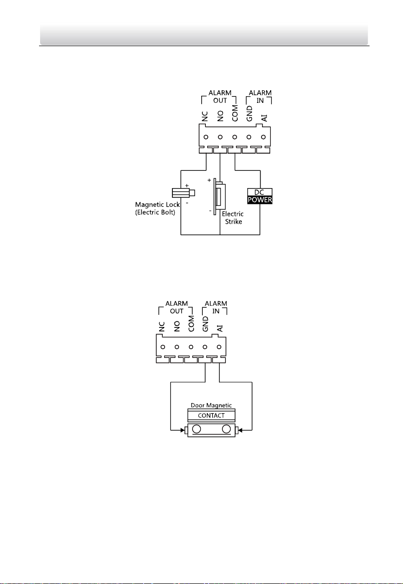
Video Intercom Vandal-Resistant Door Station·User Manual
To connect electric lock, it is required to set the output of terminal NC/ COM/ NO to be
electric lock with Batch Configuration Tool or iVMS-4200 client software or the web
browser.
Figure 3-2 Door Lock Wiring
3.2.2 Door Magnetic Wiring
To connect door magnetic, it is required to set the output of terminal AI to be door
status via Batch Configuration Tool or iVMS-4200 client software or the web browser.
Figure 3-3 Door Magnetic Wiring
3.2.3 Exit Button Wiring
To connect exit button, it is required to set the output of terminal AI to be door status
via Batch Configuration Tool or iVMS-4200 client software or the web browser.
6
Page 15
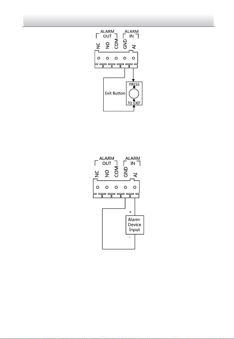
Video Intercom Vandal-Resistant Door Station·User Manual
Figure 3-4 Exit Button Wiring
3.2.4 Alarm Device Input Wiring
When you set the output of terminal AI to be custom via Batch Configuration Tool or
iVMS-4200 client software or the web browser, you can connect any alarm input device
to the door station via the terminal AI.
Figure 3-5 Alarm Device Input Wiring
7
Page 16
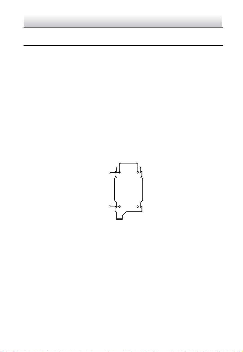
44 mm
82 mm
Video Intercom Vandal-Resistant Door Station·User Manual
4 Installation
Before you start:
Make sure the device in the package is in good condition and all the assembly parts
are included.
The device supports two ways of power supply: 12 VDC, or PoE power supply. Please
make sure your power supply matches your door station.
Make sure all the related equipment is power-off during the installation.
Make sure the wall is strong enough to withstand 4 times the weight of the door
station.
Check the specification of the product for the installation environment.
4.1 Wall Mounting Plate
To install the door station onto the wall, you are required to use a matched mounting
plate.
Figure 4-1 Wall Mounting Plate
Note: The dimensions above are theoretical. The actual size can be slightly different
from the theoretical dimension.
4.2 Wall Mounting
Steps:
1. Fix the wall mounting plate to the wall with 4 expansion screws.
8
Page 17
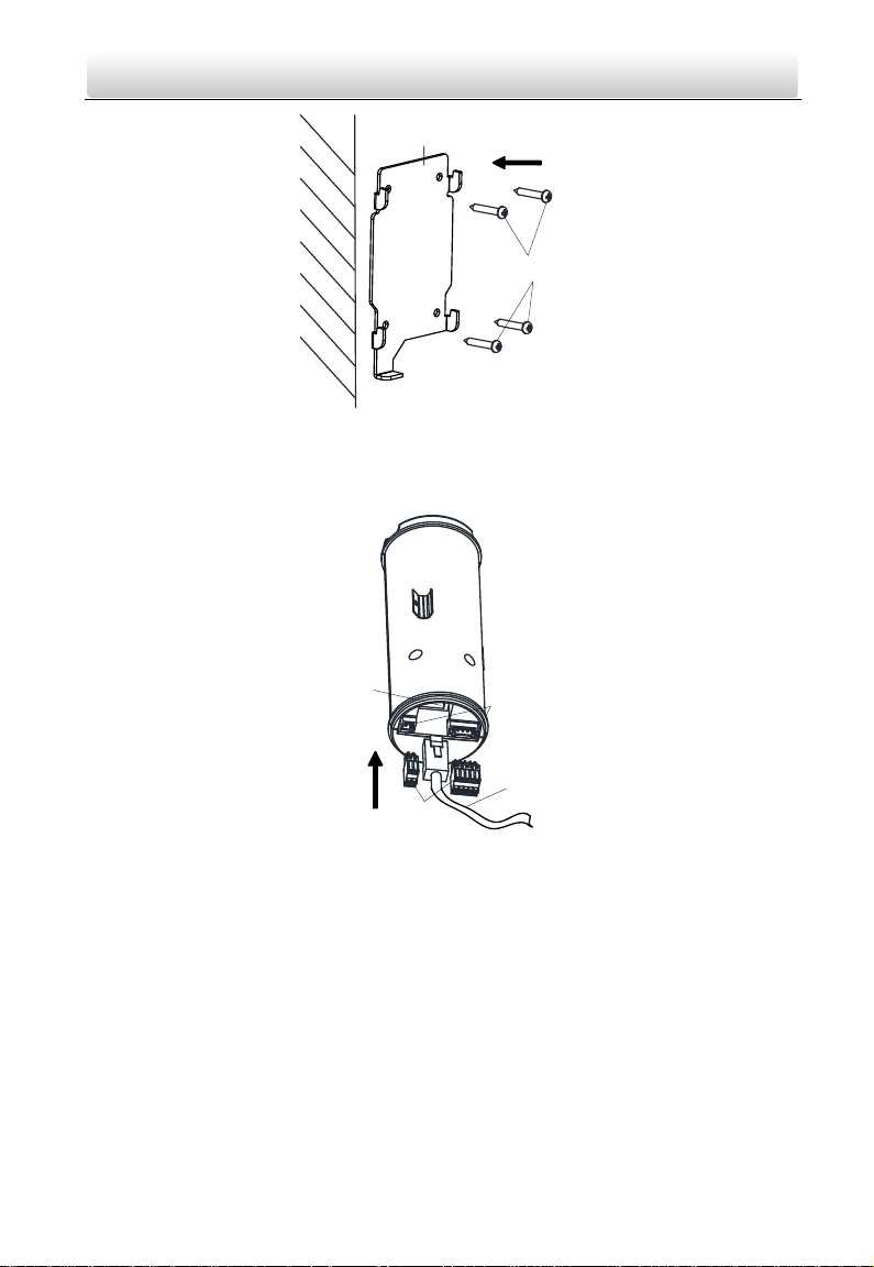
Expansion Screws
Wall Mounting Plate
Interfaces
(Power, Alarm
In, Alarm Out)
Terminal
Blocks
Network
Interface
Network
Cable
Video Intercom Vandal-Resistant Door Station·User Manual
Figure 4-2 Install the Plate
2. Insert terminal blocks into the interfaces of the door station body, and connect the
network cable.
3. Fix the door station main body to the protective shield tightly.
Figure 4-3 Insert Terminals and Network Cable
9
Page 18
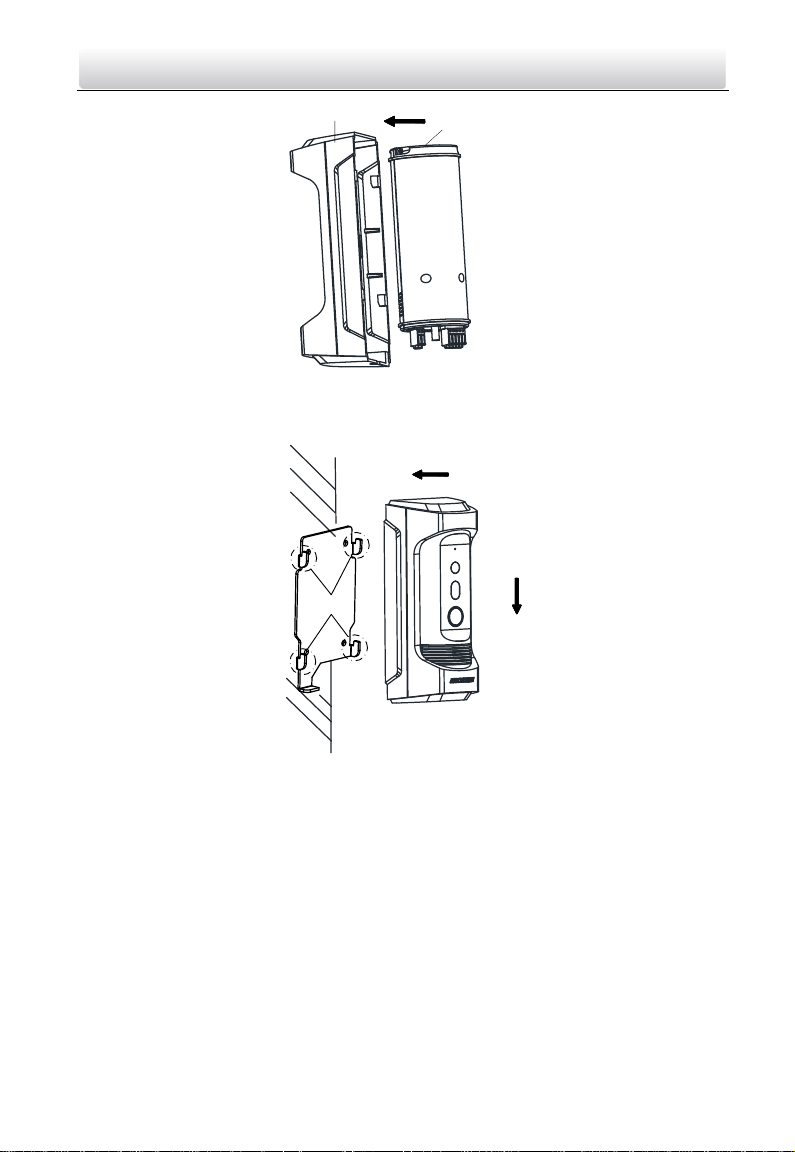
Protective Shield
Door Station
Main Body
Hooks
Video Intercom Vandal-Resistant Door Station·User Manual
Figure 4-4 Fix the Main Body to the Shield
4. Hook the door station to the wall mounting plate tightly.
5. User the set screw to secure the door station with the mounting plate.
Figure 4-5 Hook the Door Station to the Plate
10
Page 19
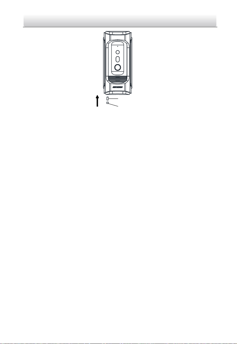
Set Screw
Rubber Plug
Video Intercom Vandal-Resistant Door Station·User Manual
Figure 4-6 Secure the Door Station
11
Page 20
Video Intercom Vandal-Resistant Door Station·User Manual
5 Activating Door Station
Purpose:
You are required to activate the device first by setting a strong password for it before
you can use the device.
Activation via Batch Configuration Tool, Activation via Web Browser, and activation via
iVMS-4200 client software are supported.
5.1 Activation via Web Browser
Steps:
1. Power on the device, and connect the device to the network.
2. Input the default IP address to the address bar of the web browser, and click Enter to
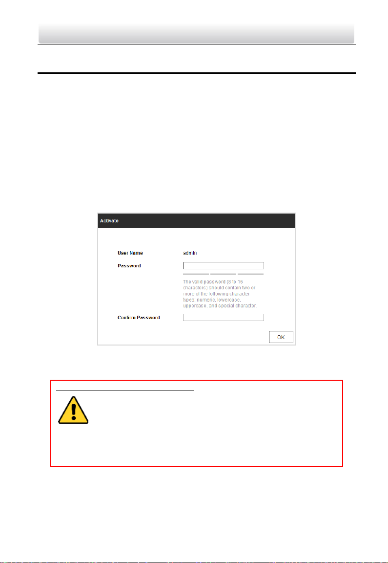
the activation interface.
Figure 5-1 Activation Interface (Web)
3. Create a password, and confirm the password.
STRONG PASSWORD RECOMMENDED– We highly recommend you create a
strong password of your own choosing (Using a minimum of 8
characters, including at least three of the following categories:
upper case letters, lower case letters, numbers, and special
characters.) in order to increase the security of your product. And we
recommend you reset your password regularly, especially in the high security
system, resetting the password monthly or weekly can better protect your
product.
4. Click OK to activate the device.
Note: The device default IP address is 192.0.0.65.
12
Page 21
Video Intercom Vandal-Resistant Door Station·User Manual
5.2 Activation via Batch Configuration Tool
Steps:
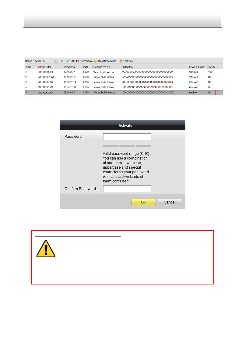
1. Run the Batch Configuration Tool.
Figure 5-2 Select Inactive Device
2. Select an inactivated device and click Activate.
Figure 5-3 Activation Interface (Batch Configuration Tool)
3. Create a password, and confirm the password.
STRONG PASSWORD RECOMMENDED– We highly recommend you create a
strong password of your own choosing (Using a minimum of 8
characters, including at least three of the following categories:
upper case letters, lower case letters, numbers, and special
characters.) in order to increase the security of your product. And we
recommend you reset your password regularly, especially in the high security
system, resetting the password monthly or weekly can better protect your
product.
4. Click OK to activate the device.
Note:
When the device is not activated, the basic operation and remote operation of device
cannot be performed.
13
Page 22
Video Intercom Vandal-Resistant Door Station·User Manual
You can hold the Ctrl or Shift key to select multiple devices in the online devices, and
click Activate to activate devices in batch.
5.3 Activation via iVMS-4200 Client Software
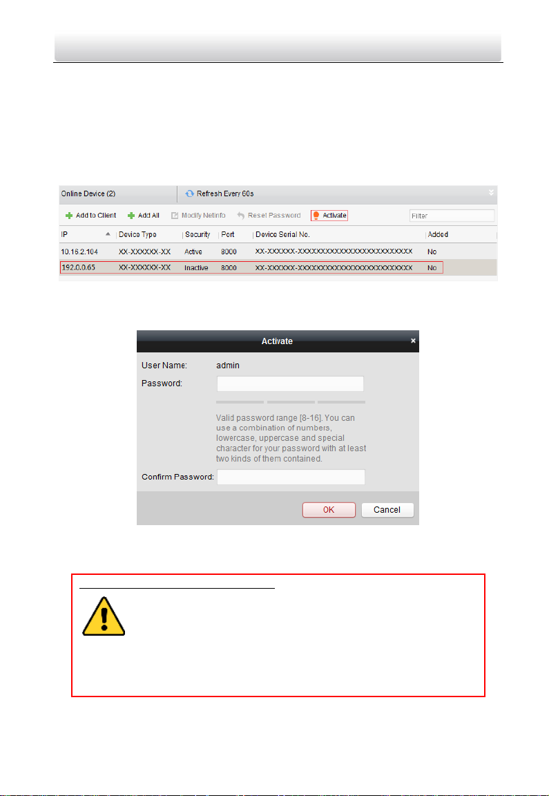
Steps:
1. Run the iVMS-4200 client software.
Figure 5-4 Select Inactive Device
2. Select an inactivated device and click Activate.
Figure 5-5 Activation Interface (iVMS-4200)
3. Create a password, and confirm the password.
STRONG PASSWORD RECOMMENDED– We highly recommend you create a
strong password of your own choosing (Using a minimum of 8
characters, including at least three of the following categories:
upper case letters, lower case letters, numbers, and special
characters.) in order to increase the security of your product. And we
recommend you reset your password regularly, especially in the high security
system, resetting the password monthly or weekly can better protect your
product.
4. Click OK to activate the device.
14
Page 23

Video Intercom Vandal-Resistant Door Station·User Manual
Note:
When the device is not activated, the basic operation and remote operation of device
cannot be performed.
You can hold the Ctrl or Shift key to select multiple devices in the online devices, and
click Activate to activate devices in batch.
15
Page 24
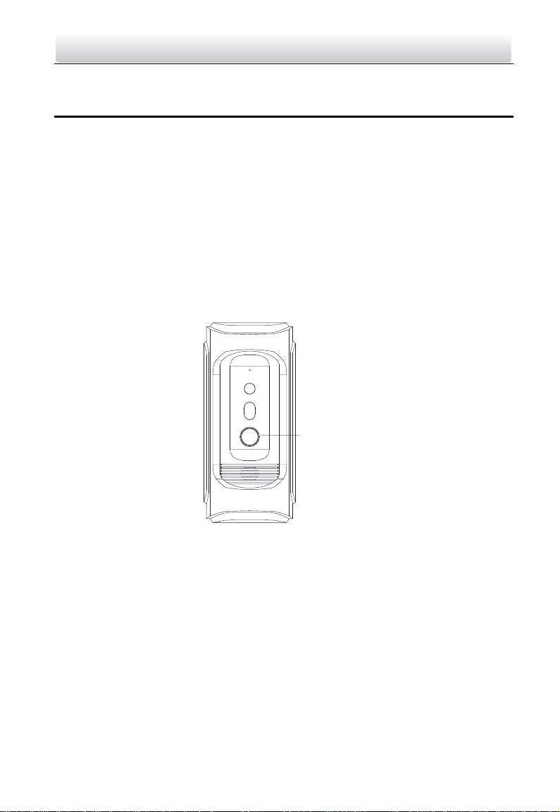
Call Button
Video Intercom Vandal-Resistant Door Station·User Manual
6 Local Operation
Before you start:
Make sure the door station has been activated.
Make sure the network cable is well-connected.
Purpose:
You can call the resident (the indoor station) or the center (the master station) via the
door station by pressing or holding the call button.
Default settings of the call button: when you press the call button, it calls the resident,
and when you hold the call button, it calls the center.
Steps:
1. Press the call button to call the resident.
2. The resident can accept/decline the calling from the door station, and unlock the
door via the indoor station.
Figure 6-1 Call Button of Door Station
Notes:
Besides the indoor station, you can also unlock the door by the master station, the
client software, and the web.
When the video intercom between you and the resident is realized, you can speak to
the resident, and the live view of door station will be displayed on the connected
indoor station.
When live view of door station is displayed on other devices or door station is calling
resident, the door station will detect the brightness of video. When the brightness is
lower than the expected threshold, the supplement light will be enabled.
When the supplement light is enabled, the backlight of key will be auto-enabled,
otherwise, the door station will detect the brightness of live view and enable the
backlight of key when the brightness of live view is lower than expected threshold.
16
Page 25
Video Intercom Vandal-Resistant Door Station·User Manual
7 Remote Operation via Web Browser
7.1 Access to the Door Station
System Requirement:
Operating System: Microsoft Windows XP SP1 and above version
CPU: 2.0 GHz or higher
RAM: 1G or higher
Display: 1024×768 resolution or higher
Web Browser: 32-bit Internet Explorer 8.0 to 11
Steps:
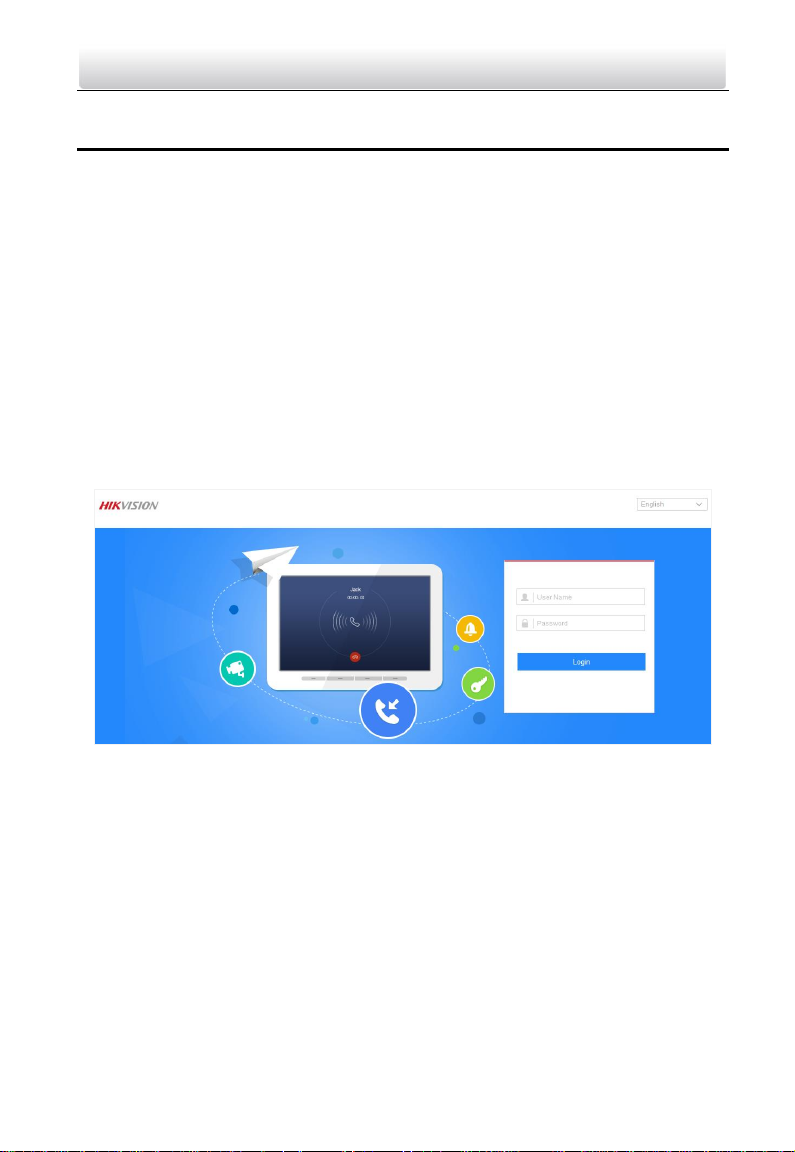
1. Open the web browser.
2. Input the IP address of the door station in the address bar, and press the Enter key to
enter the login interface.
3. Input the user name and password and click Login.
Figure 7-1 Login Interface
Note: Switch the display language from the upper-right corner among different
languages.
4. Install the plug-in before viewing the live video and operating the door station. Please
follow the installation prompts to install the plug-in.
17
Page 26
Video Intercom Vandal-Resistant Door Station·User Manual
Figure 7-2 Download and Install Plug-in
Note:
You may have to close the web browser to install the plug-in. Please reopen the web
browser and log in again after installing the plug-in.
If the device is not activated, please activate the device first.
The device IP address gets locked if the admin user performs 7 failed password
attempts.
7.2 Live View
7.2.1 Live View Page
Purpose:
The live view page allows you to view the real-time video, capture images, unlock the
door, and configure video parameters.
Log in the door station to enter the live view page, or you can click Live View on the
menu bar of the main page to enter the live view page.
Note: You can also access to the door station to get the live view in different live view
modes via iVMS-4200 client software.
18
Page 27
Video Intercom Vandal-Resistant Door Station·User Manual
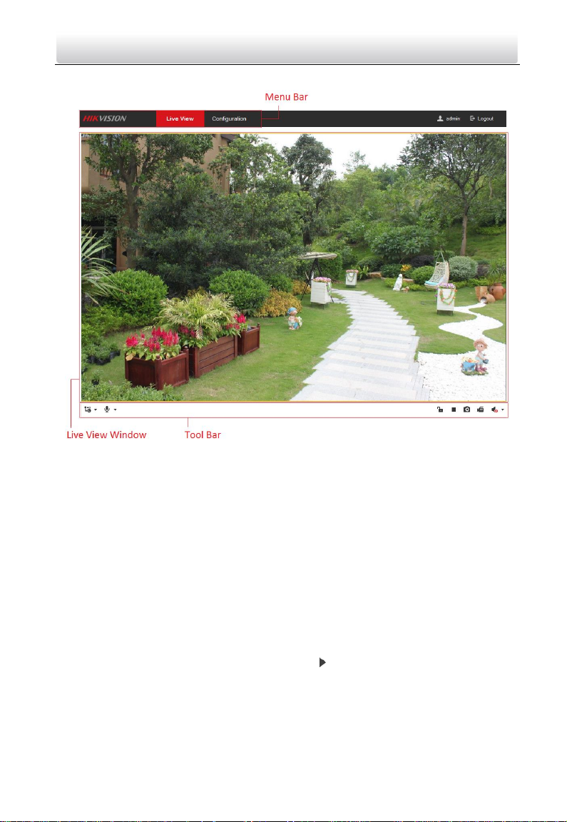
Descriptions of the live view page:
Figure 7-3 Live View Page
Menu Bar:
Click the tab to enter Live View, and Configuration page respectively.
Live View Window:
Display the live video on the display window of live view.
Toolbar:
Set the stream type, enable/disable the two-way audio, unlock the door, start/stop the
live view, capture pictures, record the video files, and adjust the audio volumes.
Note: After stopping the live view, only stream switch, two-way audio settings, door
unlocking settings are supported.
7.2.2 Starting Live View
Click Live View on the menu bar or click the icon to start the live view.
19
Page 28
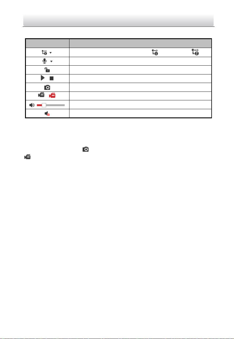
Icon
Description
Set the stream type as main stream or sub stream .
Enable/disable the two-way audio.
Unlock the door.
/
Start/stop the live view.
Capture pictures manually.
/
Start/stop recording.
Audio on and adjust the audio volume.
Mute
Video Intercom Vandal-Resistant Door Station·User Manual
Table 7-1 Descriptions of Live View Icons
Note: After stopping the live view, only stream switch, two-way audio settings, and door
unlocking settings are supported.
7.2.3 Recording and Capturing Pictures Manually
In the live view page, click on the tool bar to capture the live pictures, and click
to record the live video. The saving paths of the captured pictures and record files
can be set on the Configuration > Local page, and please refer to 7.3.1 Configuring Local
Parameters for detailed instructions.
Note: The captured picture will be saved as JPEG file or BMP file in the local PC that runs
the web browser.
7.3 Door Station Configuration
7.3.1 Configuring Local Parameters
Purpose:
Local configuration provides image file settings and record file settings. The recorded
videos and captured pictures can be saved on the local PC that runs the web browser.
Steps:
1. Enter the Local Configuration interface: Configuration > Local.
20
Page 29
Video Intercom Vandal-Resistant Door Station·User Manual
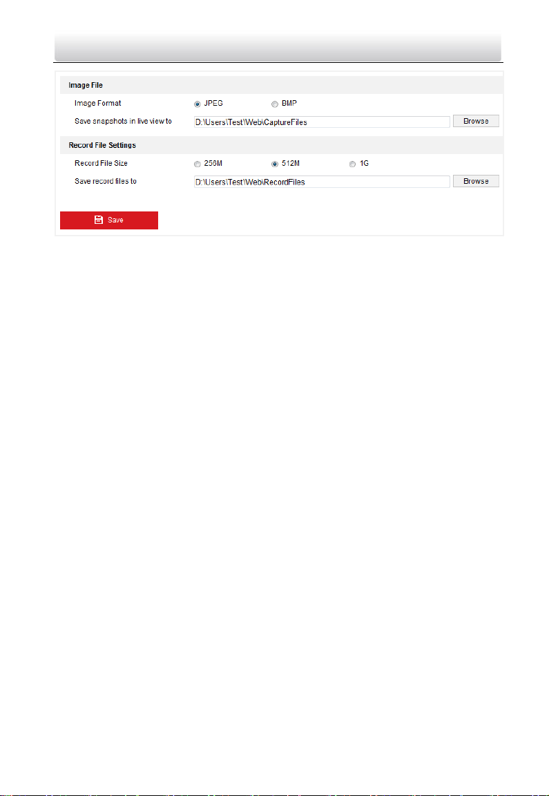
Figure 7-4 Local Configuration
2. Configure the image file settings and the record file settings.
Image File Settings: Set the saving path of the captured pictures. It is valid for the
captured pictures you captured with the web browser.
• Image Format: Set the saving format for the captured pictures. The captured
pictures can be saved in format of *.jpeg or *.bmp.
• Save snapshots in live view to: Set the saving path of the manually captured
pictures in live view mode.
Record File Settings: Set the saving path of the recorded video files. It is valid for the
record files you recorded with the web browser.
• Record File Size: Select the packed size of the manually recorded and
downloaded video files to 256M, 512M, or 1G. After the selection, the
maximum record file size is the value you selected.
• Save record file to: Set the saving path for for the manually recorded video
files.
Note: You can click Browser to change the directory for saving the pictures and
record files. And click Open to open the set folder.
3. Click Save to save the settings.
7.3.2 Configuring System Settings
Viewing Basic Information
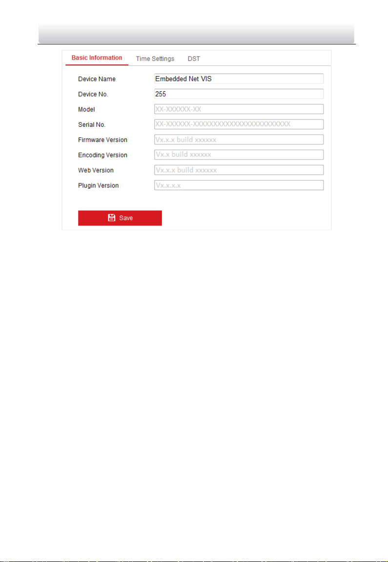
Enter the Basic Information interface: Configuration > System > System Settings > Basic
Information.
In the Basic Information interface, you can edit the device name, and the device No..
Other information of the door station, such as model, serial No., firmware version,
encoding version, web version, and plugin version, are displayed. The information
cannot be changed in this menu. It is the reference for maintenance or modification in
future.
21
Page 30
Video Intercom Vandal-Resistant Door Station·User Manual
Figure 7-5 Device Basic Information
Time and DST Settings
Purpose:
You can follow the instructions in this section to configure the time synchronization and
DST settings.
Time Settings
Steps:
1. Enter the Time Settings interface: Configuration > System > System Settings > Time
Settings.
22
Page 31

Video Intercom Vandal-Resistant Door Station·User Manual
Figure 7-6 Time Settings
2. Select the time zone of your location from the drop-down list.
3. Synchronize the time.
• Synchronizing Time by NTP Server
1) Check the NTP item to enable the NTP function.
2) Configure the following settings:
Server Address: IP address of NTP server.
NTP Port: Port of NTP server. The default NTP port No. is 123.
Interval: The time interval between the two synchronizing actions with NTP
server.
• Synchronizing Time Manually
1) Check the Manual Time Sync. item to enable the manual time synchronization
function.
2) Click the icon to open the calendar page.
3) Click on the calendar to select the date, set the time, and click OK to save.
23
Page 32

Video Intercom Vandal-Resistant Door Station·User Manual
Figure 7-7 Time Sycn. Manually
4) (Optional) You can check the checkbox of Sync. with computer time to
synchronize the time of the device with that of the local PC that runs the web
browser.
4. Click Save to save the settings.
DST
Purpose:
For regions using the summer time, DST (daylight saving time) settings can be
configured according to the actual needs.
Steps:
1. Enter the DST settings interface: Configuration > System > System Settings > DST.
2. Check the checkbox of Enable DST to enable the daylight saving time.
3. Set the start time and the end time for the DST period.
4. Select the DST bias from the drop-down list.
5. Click Save to save the settings.
24
Page 33

Video Intercom Vandal-Resistant Door Station·User Manual
Figure 7-8 DST Settings
Upgrade and Maintenance
Purpose:
On Upgrade & Maintenance interface, you can reboot the door station, restore door
station parameters, export/import configuration parameters, and upgrade firmware.
Enter the Upgrade and Maintenance interface:
Configuration > System > Maintenance > Upgrade & Maintenance
Figure 7-9 Upgrade and Maintenance
Rebooting Door Station
Click Reboot to reboot the door station.
Restoring Settings
Click Restore to restore the default parameters.
25
Page 34

Video Intercom Vandal-Resistant Door Station·User Manual
Click Restore All to restore all parameters of device and reset the device to inactive
status.
Note:
By clicking Restore, all default settings, excluding network parameters and user
information, will be restored.
By clicking Restore All, all default settings, including network parameters and user
information, will be restored. The device will be reset to inactivated status.
Exporting/Importing Configuration File
Purpose:
Configuration file is used for the batch configuration of the door station, which can
simplify the configuration steps when there are a lot of door stations needing
configuring.
Steps:
1. Click Export to export the current configuration file, and save it to the certain
place.
2. Click Browse to select the saved configuration file and then click Import to start
importing configuration file.
Note: You need to reboot the door station after importing configuration file.
Upgrading the System
Click Browse to select the local upgrade file and then click Upgrade to start remote
upgrade.
Note: The upgrading process will take 1 to 10 minutes. Do not power off the door
station during the process. The door station will reboot automatically after
upgrading.
Log Searching
Purpose:
The operation, alarm, exception and information of the door station are stored in log
files.
Steps:
1. Enter the log searching interface: Configuration > System > Maintenance > Log.
Figure 7-10 Log Searching Interface
26
Page 35

Video Intercom Vandal-Resistant Door Station·User Manual
2. Set the log search conditions to specify the search, including the major type, minor
type, start time and end time.
3. Click Search to search log files. The matched log files will be displayed on the Log
interface.
User Management
Steps:
1. Enter the User Management interface: Configuration > System > User Management.
Figure 7-11 User Management Interface
2. Click the user and click Modify.
3. Edit the password.
4. Click OK to finish the user modification.
Figure 7-12 Modify a User
27
Page 36

Video Intercom Vandal-Resistant Door Station·User Manual
Note: Only password can be changed.
7.3.3 Configuring Video Intercom Parameters
Door Station No.
Purpose:
To call the door station via the client software or to call indoor stations/the client
software/the master station via the door station successfully, you should number the
door station first. You should set the community No., the building No., the unit No., and
the floor No. for the door station.
The door station supports 2 device types: villa door station and doorphone. When it
works as a doorphone, there is no need setting the community No., the building No., the
unit No., the floor No. or the device No..
Steps:
1. Enter the device No. settings interface: Configuration > Video Intercom > Device No.
Settings.
Figure 7-13 Set the Device No.
2. Select the device type from the drop-down list: Villa Door Station or Doorphone.
3. Set the the community No., the building No., the unit No., and the floor No..
Note:
When you set 1, 2, 3, and 4 to the community No., the building No., the unit No.,
and the floor No. respectively, the No. of the door station can be written as
1-2-3-4.
When you set the device type as doorphone, there is no need setting the
community No., the building No., the unit No., or the floor No..
4. Set the device No..
Note:
The device No. requires configuring when the device type of the door station is
Villa Door Station.
28
Page 37

Video Intercom Vandal-Resistant Door Station·User Manual
If the device No. is set to 0, the door station works as the main door station.
If the device No. is larger than 0, the door station works as the sub door station.
The device No. can range from 1 to 99.
At least one main door station should be configured for each villa or building.
You can customize up to 8 sub door stations for each main door station.
5. Click Save to finish the door station No. settings.
Operation Time
Purpose:
You can set the maximum speaking duration between the door station and other video
intercom devices, and the maximum message duration of the door station on the
operation time settings interface.
Steps:
1. Enter the operation time settings interface: Configuration > Video Intercom >
Operation Time Settings.
Figure 7-14 Set the Operation Time
2. Set the Max. message duration and the Max. speaking duration.
3. Click Save to finish the operation time settings.
Note:
The maximum message time varies from 30s to 60s.
The maximum speaking duration varies from 90s to 120s.
Access Control Parameters
Purpose:
On the access control settings interface, you can set the door No., and the
door-unlocked duration.
If you set the door-unlocked duration, the door will be locked automatically beyond the
set duration once the door is open.
Steps:
1. Enter the access control settings interface: Configuration > Video Intercom > Access
Control.
29
Page 38

Video Intercom Vandal-Resistant Door Station·User Manual
Figure 7-15 Set the Access Control Parameters
2. Set the door No., and the door-unlocked duration.
Note:
The door-unlocked duration varies from 1s to 255s.
The door station, instead of the doorphone, supports configuring the access control
parameters.
I/O Input/Output
Purpose:
I/O input/output refers to the Alarm In terminal and the Alarm Out terminal. You can
connect external devices to the door station via these terminals. The door station has 1
Alarm In terminal (AI), and 1 Alarm Out terminal (NO/COM/NC).
Steps:
1. Enter the IO input/output settings interface: Configuration > Video Intercom > IO
Input/Output.
Figure 7-16 Set the IO Input/Output
2. Set the input mode: Disabled, Exit Button, Door Status, Custom.
Disabled: The function of the AI terminal is disabled.
Exit Button: The AI terminal supports connecting to the exit button.
30
Page 39

Video Intercom Vandal-Resistant Door Station·User Manual
Door Status: The AI terminal supports connecting to the door magnetic.
Custom: It is reserved.
3. Set the output mode: Disabled, Electric Lock, Custom.
Disabled: The function of the NO/NC/COM terminal is disabled.
Electric Lock: The NO/NC/COM terminal supports connecting to the electric lock
(electric strike, and magnetic lock).
Custom: It is reserved.
4. Click Save to finish the settings.
Call Button
Purpose:
You can call the indoor station (resident) and the master station (management center)
via the door station by pressing or holding down the call button.
Default settings of the call button: when you press the call button, it calls the resident;
and when you hold down the call button, it calls the center.
Steps:
1. Enter the call button settings interface: Configuration > Video Intercom > Call Button.
Figure 7-17 Set the Call Button
2. Check the checkbox of Quick Press for Calling Center to change the call button mode.
After enabling Quick Press for Calling Center, when you press the call button, it calls
the center, and when you hold down the call button, it calls the resident.
Supplement Light
Purpose:
Supplement light function gives you an option to control the IR LED.
Steps:
1. Enter the call button settings interface: Configuration > Video Intercom >
Supplement Light Settings.
31
Page 40

Video Intercom Vandal-Resistant Door Station·User Manual
Figure 7-18 Set the Supplement Light
2. Select the working mode for the door station: Video Intercom Device, Front-end
Device.
If you select the Video Intercom Device, the door station functions as a video
intercom device, while if you select the Front-end Device, the door station functions
as a camera only.
3. Select the supplement light mode: Auto, Scheduled Switch.
Auto: The camera of the door station switches between the day mode and the
night mode according to the illumination automatically.
Scheduled Switch: The camera of the door station switches between the day
mode and the night mode according to the configured time period.
4. Set the start time (day) and the end time (day).
The start time and the end time require configuring when the supplement light mode
is scheduled switch.
The camera of the door station will stay at day mode between the start time and end
time.
Note:
The interval between the start time and the end time should be more than 10s.
The start time should be earlier than the end time.
7.3.4 Configuring Network Settings
TCP/IP Settings
Purpose:
TCP/IP settings must be properly configured before you operate the door station over
network. The door station supports the IPv4.
Steps:
1. Enter the TCP/IP settings interface: Configuration > Network > Basic Settings >
TCP/IP.
32
Page 41

Video Intercom Vandal-Resistant Door Station·User Manual
Figure 7-19 Set the TCP/IP
2. Set the basic network settings, including IPv4 address, IPv4 subnet mask, and IPv4
default gateway.
3. Set the DNS server. Input the preferred DNS server, and the alternate DNS server.
4. Click Save to save the settings.
Note:
Enable DHCP, the door station can obtain an IP address automatically.
After setting the network parameters, you should close the web browser. Please
reopen the web browser and log in again with the new IP address of the door station.
Linked Network Settings
Purpose:
Linked network parameters involve the IP address of SIP server, the IP address of the
center, and the port No. of the center.
Only when the SIP server IP address is configured, can the communication among the
door station and the indoor station be realized.
Only when the center IP address is configured, can the door station call the center.
Steps:
1. Enter the linked network settings interface: Configuration > Network > Basic
Settings > Linked Network.
33
Page 42

Video Intercom Vandal-Resistant Door Station·User Manual
Figure 7-20 Set the Linked Network
2. Set the SIP server address, the center IP address, and the center port.
3. Click Save to save the settings.
Port Settings
Purpose:
You can set the port No. of the door station, e.g. HTTP port, HTTPS port, and server port.
Steps:
1. Enter the port settings interface: Configuration > Network > Basic Settings > Port.
Figure 7-21 Set the Port
2. Set the HTTP port, HTTPS port, and server port of the door station.
HTTP Port: The default HTTP port No. is 80, and it can be changed to any port No.
which is not occupied. The unoccupied HTTP port ranging from 1 to 65535 is
available.
HTTPS Port: The default HTTPS port No. is 443, and it can be changed to any port
No. which is not occupied. The unoccupied HTTPS port ranging from 1 to 65535 is
available.
Server Port: The default server port No. is 8000, and it can be changed to any port
which is not occupied. The unoccupied server port ranging from 2000 to 65535 is
available.
3. Click Save to save the settings.
Note:
34
Page 43

Video Intercom Vandal-Resistant Door Station·User Manual
A reboot is required for the settings to take effect.
FTP Settings
Purpose:
You can configure the FTP server related information to enable the uploading of the
captured pictures to the FTP server.
Steps:
1. Enter the FTP Settings interface: Configuration > Network > Advanced Settings > FTP.
Figure 7-22 FTP Settings
2. Check the checkbox of Enable FTP.
3. Configure the FTP settings; and the user name and password are required for logging
in the FTP server.
For your privacy and to better protect your system against security
risks, we strongly recommend the use of strong passwords for all
functions and network devices. The password should be something of
your own choosing (using a minimum of 8 characters, including at
least three of the following categories: upper case letters, lower case letters,
numbers and special characters) in order to increase the security of your product.
Proper configuration of all passwords and other security settings is the
responsibility of the installer and/or end-user.
35
Page 44

Video Intercom Vandal-Resistant Door Station·User Manual
Directory: In the directory structure, you can select the root directory, parent
directory and child directory.
Anonymous Access to the FTP Server (The user name and password won’t be
required.): Check the checkbox of Anonymous to enable the anonymous access to
the FTP server.
Note: The anonymous access function must be supported by the FTP server.
4. Click Save to save the settings.
Email Settings
Purpose:
The system can be configured to send an Email notification to all designated receivers if
an alarm event is detected, e.g., motion detection event.
Before you start:
Please configure the DNS Server settings under Configuration > Network > Basic
Settings > TCP/IP before using the Email function.
Steps:
5. Enter the TCP/IP Settings (Configuration > Network > Basic Settings > TCP/IP) to set
the IPv4 Address, IPv4 Subnet Mask, IPv4 Default Gateway and the Preferred DNS
Server.
Note: Please refer to Configuring TCP/IP Settings for detailed information.
6. Enter the Email Settings interface: Configuration > Network >Advanced Settings >
Email.
Figure 7-23 Email Settings
36
Page 45

Video Intercom Vandal-Resistant Door Station·User Manual
7. Configure the following settings:
Sender: The name of the email sender.
Sender’s Address: The email address of the sender.
SMTP Server: IP address or host name (e.g., smtp.263xmail.com) of the SMTP
Server.
SMTP Port: The SMTP port. The default TCP/IP port for SMTP is 25 (not secured).
E-mail Encryption: None and SSL are selectable. Select SSL if it is required by the
SMTP server.
Authentication (optional): If your email server requires authentication, check this
checkbox to use authentication to log in to this server and input the login user
name and password.
For your privacy and to better protect your system against security
risks, we strongly recommend the use of strong passwords for all
functions and network devices. The password should be something
of your own choosing (using a minimum of 8 characters, including
at least three of the following categories: upper case letters, lower case letters,
numbers and special characters) in order to increase the security of your
product.
Proper configuration of all passwords and other security settings is the
responsibility of the installer and/or end-user.
The Receiver table: Select the receiver to which the email is sent. Up to 3
receivers can be configured.
Receiver: The name of the user to be notified.
Receiver’s Address: The email address of user to be notified.
8. Click Save to save the settings.
HTTPS Settings
Purpose:
HTTPS provides authentication of the web site and associated web server that one is
communicating with, which protects against Man-in-the-middle attacks. Perform the
following steps to set the port number of https.
E.g., if you set the port number as 443 and the IP address is 192.168.1.64, you may
access the device by inputting https://192.168.1.64:443 via the web browser.
Steps:
1. Enter the HTTPS settings interface: Configuration > Network > Advanced Settings >
HTTPS.
The certificate information is presented on the HTTPS settings interface.
37
Page 46

Video Intercom Vandal-Resistant Door Station·User Manual
Figure 7-24 HTTPS Settings
2. Check the checkbox of Enable to enable the function.
3. Click Save to save the settings.
7.3.5 Configuring Video/Audio Settings
Video Settings
Steps:
1. Enter the video settings interface: Configuration > Video/Audio > Video.
Figure 7-25 Video Settings (Main Stream)
2. Select the stream type of the door station to main stream (continuous) or sub-stream.
The main stream is usually for the live view with good bandwidth, and the
sub-stream can be used for the live view when the bandwidth is limited.
38
Page 47

Video Intercom Vandal-Resistant Door Station·User Manual
3. Set the following parameters for the selected main stream or sub-stream.
Video Type: Select the stream type to video stream, or video & audio composite
stream. The audio signal will be recorded only when the Video Type is Video &
Audio.
Resolution: For the main stream, the resolution of the video output is 1280 x 720P,
and for the sub stream, the resolution of the video output is 640 x 480.
Bitrate Type: Select the bitrate type to constant or variable.
Video Quality: If you set the bitrate type as constant, the video quality is medium.
If you set the bitrate type as variable, multiple choices of the video quality can be
selected: Lowest, Lower, Low, Medium, Higher, and Highest.
Frame Rate: Set the frame rate. The frame rate describes the frequency at which
the video stream is updated and it is measured by frames per second (fps). A
higher frame rate is advantageous when there is movement in the video stream,
as it maintains image quality throughout.
Max. Bitrate: Set the max. bitrate. For the main stream, the max. bitrate ranges
from 32 to 4096 Kbps, and for the sub stream, the max. bitrate ranges from 32 to
2048 Kbps. The higher value corresponds to the higher video quality, but the
better bandwidth is required.
Video Encoding: If the stream type is set to main stream, H.264 is selectable, and
if the stream type is set to sub stream, H.264 is selectable.
4. Click Save to save the settings.
Volume Settings
Steps:
1. Enter the audio settings interface: Configuration > Video/Audio > Volume.
Figure 7-26 Volume Settings
2. Configure the input volume and the output volume, both of which range from 0 to 10.
3. Click Save to save the settings.
7.3.6 Configuring Image Parameters
Display Settings
Purpose:
39
Page 48

Video Intercom Vandal-Resistant Door Station·User Manual
You can set the image quality of the door station, including brightness, contrast,
saturation, sharpness, etc.
Steps:
1. Enter the display settings interface:
Configuration > Image> Display Settings
Figure 7-27 Display Settings
2. Set the image parameters of the door station.
Image Adjustment
Brightness describes bright of the image, which ranges from 1 to 100, and the
default value is 50.
Contrast describes the contrast of the image, which ranges from 1 to 100, and the
default value is 50.
Saturation describes the colorfulness of the image color, which ranges from 1 to
100, and the default value is 50.
Hue describes the quality of the image color, which ranges from 1 to 100, and the
default value is 50.
Sharpness describes the edge contrast of the image, which ranges from 1 to 100,
and the default value is 50.
Video Adjustment
Video Standard: 50 Hz and 60 Hz are selectable. Choose according to the different
video standards. Normally, 50 Hz is for PAL standard and 60 Hz for NTSC standard.
OSD Settings
Purpose:
OSD (On-screen Display) refers to the camera name, time/date format, and display
mode on the live view.
Steps:
40
Page 49

Video Intercom Vandal-Resistant Door Station·User Manual
1. Enter the OSD Settings interface: Configuration > Image > OSD Settings.
Figure 7-28 OSD Settings
2. Check the corresponding checkbox to select the display of camera name, date or
week if required.
3. Edit the camera name in the text field of Camera Name.
4. Select from the drop-down list to set the time format, date format, and display mode.
5. Set overlaid text if needed.
1) Check the checkbox on the left to enable the on-screen display.
2) Input the desired information in the textbox.
Notes: Up to 4 texts are configurable.
6. You can use the mouse to click-and-drag the red text frames in the live view window
to adjust the OSD position.
7. Click Save to save the settings.
7.3.7 Configuring Event Settings
Motion Detection
Purpose:
Motion detection detects the moving objects in the configured surveillance area, and a
series of actions can be taken when the alarm is triggered.
Motion detection configuration adopts the same set of motion detection parameters in
the daytime and at night.
Tasks 1: Set the Motion Detection Area
Steps:
1. Enter the motion detection settings interface: Configuration > Event > Basic Event >
Motion Detection.
41
Page 50

Video Intercom Vandal-Resistant Door Station·User Manual
Figure 7-29 Motion Detection Settings
2. Check the checkbox of Enable Motion Detection.
3. Click Draw Area. Drag the mouse on the live video to draw a motion detection area.
Click Stop Drawing to finish drawing one area.
4. (Optional) Click Clear All to clear all of the areas.
5. (Optional) Move the slider to set the sensitivity of the detection.
Ta sk 2: Set the Arming Schedule for Motion Detection
Steps:
1. Click Arming Schedule to edit the arming schedule.
42
Page 51

Video Intercom Vandal-Resistant Door Station·User Manual
Figure 7-30 Arming Schedule Setting
2. Click on the time bar and drag the mouse to select the time period.
Note: Click on the selected time period, you can adjust the time period to the desired
time by either moving the time bar or input the exact time period.
3. (Optional) Click Delete to delete the current arming schedule, or click Save to save the
settings.
4. Move the mouse to end of each day, a green copy icon appears. You can click the icon
to copy the current time schedule to other days.
Figure 7-31 Copy to Window
5. Click Save to save the settings.
Note: The time of each period can’t be overlapped. Up to 8 periods can be configured
for each day.
Task 3: Set the Linkage Method for Motion Detection
Click Linkage Method and check the checkbox to select the linkage method. Send email,
notify surveillance center, and upload to FTP are selectable.
43
Page 52

Video Intercom Vandal-Resistant Door Station·User Manual
Figure 7-32 Linkage Method Settings
Notify Surveillance Center: Send an exception or alarm signal to remote
management software when an event occurs.
Send Email: Send an email with alarm information to a user or users when an
event occurs.
Note: To send the Email when an event occurs, please refer to Section 5.3.8 to
complete Email setup in advance.
Upload to FTP: Capture the image when an alarm is triggered and upload the
picture to the configured FTP server.
Notes: Set the FTP address and the remote FTP server first. Refer to Section 5.3.7
Configuring FTP Settings for detailed information.
Alarm Uploading
Purpose:
Delayed door alarm will be triggered when the door is unlocked beyond the
door-unlocked duration.
Steps:
1. Enter the alarm uploading settings interface: Configuration > Event > Basic Event >
Alarm Uploading.
44
Page 53

Video Intercom Vandal-Resistant Door Station·User Manual
Figure 7-33 Alarm Uploading Settings
2. Check the checkbox of Delayed Door Alarm.
3. Click Save to save the settings.
45
Page 54

Video Intercom Vandal-Resistant Door Station·User Manual
8 Remote Operation via Batch
Configuration Tool
Purpose:
You can operate configure the device remotely via the Batch Configuration Tool. Before
operating and configuring the device via the Batch Configuration Tool, you should
activate the device first. For detail information about activation, please refer to 5
Activating Door Station.
8.1 Editing Network Parameters
Purpose:
To operate and configure the device via LAN (Local Area Network), you need connect the
device in the same subnet with you PC. You can edit network parameters via batch
configuration tool, and iVMS-4200 client software. Here take editing network
parameters via batch configuration tool as example.
Steps:
1. Select an online activated device and click Edit NET Parameters.
Figure 8-1 Click Edit NET Parameters Button
2. Change the device IP address and gateway address to the same subnet with your
computer. Or enable DHCP to get the IP address automatically.
3. Input the password and click OK to activate the network parameters modification.
Figure 8-2 Edit Network Parameters
46
Page 55

Video Intercom Vandal-Resistant Door Station·User Manual
Note:
The default port No. is 8000.
After editing the network parameters of device, you should add the devices to the
device list again.
8.2 Adding Device
Before you start:
Make sure the device to be added has been activated.
Purpose:
To configure the activated device via batch configuration tool and iVMS-4200 client
software remotely, you should add the device to the tool or the software firstly.
3 ways for adding the device are supported: adding active online devices within your
subnet, adding device by IP address, and adding device by IP segment.
8.2.1 Adding Online Device
Before you start:
Make sure the device to be added is in the same subnet with your computer. Otherwise,
please edit network parameters first.
Steps:
1. Select an active online device or hold the Ctrl or Shift key to select multiple devices in
the online devices list.
Figure 8-3 Online Devices Interface
2. Click to pop up the login dialog box.
Figure 8-4 Login Dialog Box
47
Page 56

Video Intercom Vandal-Resistant Door Station·User Manual
3. Input the user name and password.
4. Click OK to save the settings.
Note:
Only devices successfully logged in will be added to the device list for configuration.
If you add devices in batch, please make sure selected devices have the same user
name and password.
8.2.2 Adding by IP Address
Purpose:
You can add the device by inputting IP address.
Steps:
1. Click to pop up the adding devices dialog box.
Figure 8-5 Click Adding Button
2. Select IP Address in the adding mode drop-down list.
3. Input the IP address, and set the port No., user name and password of the device.
Figure 8-6 Adding by IP Address
4. Click OK to add the device to the device list.
Note:
You cannot add the device(s) to the device list if the user name and password are not
identical.
When you add devices by IP Address, IP Segment or Port No., the devices should be
online devices.
8.2.3 Adding by IP Segment
Purpose:
48
Page 57

Video Intercom Vandal-Resistant Door Station·User Manual
You can add many devices at once whose IP addresses are among the IP segment.
Steps:
1. Click to pop up the adding devices dialog box.
Figure 8-7 Click Adding Button
2. Select IP Segment in the adding mode drop-down list.
3. Set the Start IP Address and End IP Address.
4. Input port No., user name, and password.
Figure 8-8 Adding by IP Segment
5. Click OK to search and add the devices whose IP addresses are within the range of the
defined IP segment to the device list.
8.3 Configuring Devices Remotely
In the device list area, select a device and click or to enter
the remote configuration interface.
Figure 8-9 Remote Configuration
Note: The icon appears by hovering the mouse over a piece of device information.
8.3.1 System
Click System on the remote configuration interface to display the device information:
Device Information, General, Time, System Maintenance, and User, and so on.
49
Page 58

Video Intercom Vandal-Resistant Door Station·User Manual
Device Information
Click System –> Device Information to enter device basic information interface. You can
view basic information (the device type, and serial No.), and version information of the
device.
Figure 8-10 Device Information
General
Click System –> General to enter device general parameters settings interface. You can
view and edit the device name and device ID.
Figure 8-11 General
Time
Steps:
1. Click System –> Time to enter the device time settings interface.
50
Page 59

Video Intercom Vandal-Resistant Door Station·User Manual
Figure 8-12 Time Settings
2. Select Time Zone or Enable NTP.
Time Zone
1) Select a time zone from the drop-down list menu.
2) Click the Synchronization button.
NTP
1) Check the checkbox of Enable NTP to enable NTP.
2) Input the server address, NTP port, and synchronization interval.
DST
1) Check the checkbox of Enable DST to enable DST.
2) Input the start time and end time of DST, and set the DST bias.
3. Click Save to save and realize the time settings.
Note: The default port No. is 123.
System Maintenance
Purpose:
You can operate the system management and remote upgrading on the system
maintenance interface.
Steps:
1. Click System –> System Maintenance to enter the system maintenance interface.
51
Page 60

Video Intercom Vandal-Resistant Door Station·User Manual
Figure 8-13 System Maintenance
2. Click Reboot and the system reboot dialog box pops up. Click Yes to reboot the
system.
3. Click Restore Default Settings to restore the default parameters.
4. Click Restore All to restore all parameters of device and reset the device to inactive
status.
5. Click Import Configuration File and the import file window pops up. Select the path
of remote configuration files. Click Open to import the remote configuration file. The
configuration file is imported and the device will reboot automatically.
Figure 8-14 Import File
6. Click Export Configuration File and the export file window pops up. Select the saving
path of remote configuration files and click Save to export the configuration file.
52
Page 61

Video Intercom Vandal-Resistant Door Station·User Manual
Figure 8-15 Export File
7. Click to select the upgrade file and click Upgrade to remote upgrade the device.
The process of remote upgrade will be displayed in the process bar.
Figure 8-16 Remote Upgrade
Note:
By clicking Restore Default Settings, all default settings, excluding network
parameters and user information, will be restored.
By clicking Restore All, all default settings, including network parameters and user
information, will be restored. The device will be reset to inactivated status.
User
Purpose:
You can edit the password for logging in the device.
Steps:
1. Click System –> User to enter the user information editing interface.
53
Page 62

Video Intercom Vandal-Resistant Door Station·User Manual
Figure 8-17 Select User Name
2. Select the user to edit and click Modify to enter the user parameter interface.
Figure 8-18 Modify User Information
3. Input the new password, and confirm it.
4. Click Save to realize the editing of password.
Note:
The new password and confirm password should be identical.
After editing the password of device, click button from the device list, the added
device will not be there. You should add the device again with new password to
operate the remote configuration.
8.3.2 Video Intercom
Click Video Intercom on the remote configuration interface to enter the video intercom
parameters settings: Device Number Configuration, Time Parameters, Password, Zone
Configuration, IP Camera Information, and Volume Input and Output Configuration, and
so on.
54
Page 63

Video Intercom Vandal-Resistant Door Station·User Manual
ID Configuration
Purpose:
To call the door station via the client software or to call indoor stations/the client
software/the master station via the door station successfully, you should number the
door station first. You should set the community No., the building No., the unit No., and
the floor No. for the door station.
The door station supports 2 kinds of device type: villa door station and doorphone.
When it works as a doorphone, there is no need setting the community No., the building
No., the unit No., the floor No. or the device No..
Steps:
1. Click Video Intercom –> ID Configuration to enter device ID configuration interface.
Figure 8-19 Door Station (V Series)
2. Select the device type from the drop-down list, and set the corresponding
information.
3. Click Save to enable the device number configuration.
Note:
For main door station, the serial No. is 0.
For sub door station, the serial No. is larger than 0. Serial No. ranges from 1 to 99.
For each villa or building, at least one main door station should be configured, and
sub door stations can be customized.
For one main door station, at most 8 sub door stations can be customized.
Select doorphone as device type, and the serial No. is not necessary to configure.
Please utilize the doorphone along with the main door station (V Series or D Series).
V series door station cannot be used as outer door station.
Time Parameters
Steps:
1. Click Video Intercom –> Time Parameters to enter time parameters settings
interface.
2. Configure the maximum speaking duration, and the maximum message duration.
3. Click Save.
55
Page 64

Video Intercom Vandal-Resistant Door Station·User Manual
Figure 8-20 Time Parameters
Note: For door station, maximum speaking time and maximum message time should be
configured. Maximum speaking time varies from 90s to 120s, and maximum message
time varies from 30s to 60s.
Access Control and Elevator
Steps:
1. Click Video Intercom –> Access Control and Elevator to enter the access control and
elevator settings interface.
Note: The door station does not support the elevator controlling function.
Figure 8-21 Access Control and Elevator Settings
2. Select the door No.
3. Set the door-unlocked duration.
Note: If you set the door-unlocked duration, after you open the door, the door will
be locked automatically beyond the set duration.
4. (Optional) Enable Delay Door Alarm.
Note: Delayed door alarm will be triggered when the door is unlocked beyond the
door-unlocked duration.
5. Click Save to enable the settings.
56
Page 65

Video Intercom Vandal-Resistant Door Station·User Manual
Note: This function only applies to door stations, except for the doorphone.
IO Input and Output
IO input/output refers to the Alarm In terminal and the Alarm Out terminal. You can
connect external devices to the door station via these terminals. The door station has 1
Alarm In terminal (AI), and 1 Alarm Out terminal (NO/COM/NC).
Steps:
1. Click Video Intercom -> IO Input and Output to enter the IO input and output
interface.
Figure 8-22 IO Input/Output Configuration
2. Set the input mode: Disabled, Exit Button, Door Status, Custom.
Disabled: The function of the AI terminal is disabled.
Exit Button: The AI terminal supports connecting to the exit button.
Door Status: The AI terminal supports connecting to the door magnetic.
Custom: It is reserved.
3. Set the output mode: Disabled, Electric Lock, Custom.
Disabled: The function of the NO/NC/COM terminal is disabled.
Electric Lock: The NO/NC/COM terminal supports connecting to the electric lock
(electric strike, and magnetic lock).
Custom: It is reserved.
4. Click Save to enable the settings.
Volume Input and Output
Steps:
1. Click Video Intercom -> Volume Input/Output to enter the volume input and output
interface.
57
Page 66

Video Intercom Vandal-Resistant Door Station·User Manual
Figure 8-23 Volume Configuration
2. Slide the slider to adjust the volume input and volume output.
3. Click Save to enable the settings.
Call Button
Steps:
1. Click Video Intercom -> Call Button to enter the call button settings interface.
Figure 7-1 Call Button Settings Interface
2. Check the checkbox of Quick Press for Calling Center.
3. Click Save to enable the settings.
Note: If enabling Quick Press for Calling Center, you should call resident by holding
down the call button, and call center by quickly pressing the call button.
Motion Detection
Purpose:
Motion detection detects the moving objects in the configured surveillance area, and a
series of actions can be taken when the alarm is triggered.
Motion detection configuration adopts the same set of motion detection parameters in
the daytime and at night.
Task 1: Set the Motion Detection Area
Steps:
1. Click Video Intercom -> Motion Detection to enter the motion detection settings
interface.
58
Page 67

Video Intercom Vandal-Resistant Door Station·User Manual
Figure 7-2 Motion Detection Settings Interface
2. Check the checkbox of Enable Motion Detection.
3. Click and drag the mouse on the live video to draw motion detection area.
4. (Optional) Click , then the whole live video screen belongs to the draw motion
detection area.
5. (Optional) Click to delete the selected motion detection area.
6. (Optional) Click to delete all motion detection areas.
7. (Optional) Move the slider to set the sensitivity of the detection.
Task 2: Set the Arming Schedule for the Motion Detection
Steps:
1. Click the arming schedule drop-down list to enter the arming schedule settings
interface.
Figure 7-3 Arming Schedule Settings
59
Page 68

Video Intercom Vandal-Resistant Door Station·User Manual
2. Edit a template and save it.
Note: Up to 9 templates are supported to be set manually.
1) Select a template, e.g., Template 01, and click Edit on the upper right corner to the
template editing interface.
Figure 7-4 Template Editing Interface
2) Click on the time bar and drag the mouse to the time period.
Note: Click on the selected time period, you can adjust the time period to the
desired time by either moving the time bar or input the exact time period.
3) Select a time period, click to delete the selected one.
4) Click to delete all configured time periods.
5) Select a time period, click to copy the selected time period to other days.
Figure 7-5 Copy to
6) (Optional) You can rename the template 1.
7) Click save the save the settings.
Note: The time of each period can’t be overlapped. Up to 8 periods can be
configured for each day.
3. (Optional) You can select All-day Template or Weekday Template.
All-day Template: The motion detection area is armed all the day.
60
Page 69

Video Intercom Vandal-Resistant Door Station·User Manual
Weekday Template: The motion detection area is armed during the working time
period of each day. The working time period here is from 8 am to 8 pm.
4. (Optional) If you select Custom, you should manually set the time period. The way is
same with the settings of template 1.
Task 3: Set the Linkage Method for Motion Detection
Check the checkbox to select the linkage method. Send email, notify surveillance center,
and upload to FTP are selectable.
Figure 8-24 Linkage Method Settings
Notify Surveillance Center: Send an exception or alarm signal to remote
management software when an event occurs.
Email Linkage: Send an email with alarm information to a user or users when an
event occurs.
Note: To send the Email when an event occurs, please complete the Email
configuration in advance in Section 8.3.3.
Upload Picture to FTP: Capture the image when an alarm is triggered and upload
the picture to the configured FTP server.
Notes: Set the FTP address and the remote FTP server first. Please complete the
FTP configuration in advance in Section 8.3.3.
Working Mode
Click Video Intercom -> Work Mode to enter the working mode settings interface.
Figure 7-6 Working Mode Settings Interface
If you select the Intercom Mode, the door station functions as a video intercom device,
while if you select the IPC Mode, the door station functions as a camera only.
Supplement Light
Steps:
1. Click Video Intercom -> Supplement Light to enter the supplement light mode
settings interface.
61
Page 70

Video Intercom Vandal-Resistant Door Station·User Manual
Figure 7-7 Supplement Light Mode Settings Interface
2. Select the supplement light mode: Auto, Schedule.
Auto: The camera of the door station switches between the day mode and the
night mode according to the illumination automatically.
Schedule: The camera of the door station switches between the day mode and the
night mode according to the configured time period.
3. Set the start time (day) and the end time (day).
The start time and the end time require configuring when the supplement light mode
is scheduled switch.
The camera of the door station will stay at day mode during the start time and end
time.
Note:
The interval between the start time and the end time should be more than 10s.
The start time should be earlier than the end time.
8.3.3 Network
Local Network Configuration
Steps:
1. Click Network -> Local Network Configuration to enter local network configuration
interface.
Figure 8-25 Local Network Parameters
2. Input the local IP address, subnet mask, gateway address, port No., and HTTP port.
3. Click Save to enable the settings.
Note:
The default port No. is 8000, and the default HTTP port No. is 80.
62
Page 71

Video Intercom Vandal-Resistant Door Station·User Manual
After editing the local network parameters of device, you should add the devices to
the device list again.
Linked Devices Network Configuration
Purpose:
In the linked devices network configuration interface, you can configure the network
parameters of master stations, SIP servers and management centers of the same LAN.
The devices can be linked to the door station and realize the linkage between these
devices.
Steps:
1. Click Network -> Linked Network Configuration to enter linked network configuration
interface.
Figure 8-26 Linked Network Configuration
2. Input the SIP server IP address, the management center IP address, and the
management center port No..
3. Click Save to enable the settings.
Note:
After adding SIP Server Address IP, the video intercom of same community: video
intercom between indoor stations of different building, calling indoor station from
outer door station and video intercom between management center and indoors.
After adding management center IP Address, the events can be uploaded to the
management center.
FTP
Steps:
1. Click Network -> FTP to enter the FTP parameters interface.
63
Page 72

Video Intercom Vandal-Resistant Door Station·User Manual
Figure 8-27 FTP Configuration
2. Check the checkbox of Enable Main FTP.
3. Select IP address from the drop-down list of server mode.
4. Input the FTP server address, and port No..
5. Check the checkbox to enable the anonymity (optional).
6. Input the name and password.
7. Select the directory structure and set the separator, naming item, and naming
element.
8. Click Save to enable the FTP parameters settings.
Note:
The default port No. is 21.
To enable anonymity or not is according to whether the FTP server enables
anonymity.
After configuring the FTP parameters, the captured pictures of door station will be
uploaded to the FTP server automatically.
This function only applies to the door station, except for the doorphone.
Email
Purpose:
The system can be configured to send an Email notification to all designated receivers if
an alarm event is detected, e.g., motion detection event.
Before you start:
Please configure the local network parameters and the DNS Server settings before using
the Email function.
Steps:
1. Set the local IP address, subnet mask, and default gateway in Local Network
Configuration interface.
64
Page 73

Video Intercom Vandal-Resistant Door Station·User Manual
2. Set the DNS server address in the Advanced Settings interface.
3. Click Network -> Email to enter the email settings interface.
Figure 8-28 Email Configuration
4. Input the user name, password, and confirm the password.
5. Set the sender/recipient details.
1) Select Sender or Receiver, and click Modify to pop up the information settings
window.
Figure 8-29 Information Settings
2) Input the user name, and the email address.
6. Set the following parameters.
SMTP Server: IP address or host name (e.g., smtp.263xmail.com) of the SMTP
Server.
SMTP Port: The SMTP port. The default TCP/IP port for SMTP is 25 (not secured).
E-mail Encryption: Close and SSL are selectable. Select SSL if it is required by the
SMTP server.
Server Authentication (optional): If your email server requires authentication,
check this checkbox to use authentication to log in to this server and input the
login user name and password.
65
Page 74

Video Intercom Vandal-Resistant Door Station·User Manual
For your privacy and to better protect your system against security
risks, we strongly recommend the use of strong passwords for all
functions and network devices. The password should be something
of your own choosing (using a minimum of 8 characters, including
at least three of the following categories: upper case letters, lower case letters,
numbers and special characters) in order to increase the security of your
product.
Proper configuration of all passwords and other security settings is the
responsibility of the installer and/or end-user.
7. Click Save to save the settings.
HTTPS
Steps:
1. Click Network -> HTTPS to enter the HTTPS parameters interface.
Figure 8-30 HTTPS Configuration
2. Check the checkbox of Enable HTTPS.
3. Click Save to save the settings.
Note: The default HTTPS port No. is 443.
Advanced Settings
In the advanced settings interface, you can configure the DNS server.
Steps:
1. Click Network -> Advanced Settings to enter the DNS server settings interface.
66
Page 75

Video Intercom Vandal-Resistant Door Station·User Manual
Figure 8-31 DNS Server Settings Interface
2. Set the DNS server address 1 and the DNS server address 2.
3. Click Save to save the settings.
8.3.4 Video Display
Video Parameters
Steps:
1. Click Video Display -> V ideo Parameters to enter the video parameters interface.
Figure 8-32 Video Display
2. Select the channel No..
3. Select the resolution, the frame rate, and the video standard (PAL and NTSC can be
selected).
4. Set the brightness, contrast, hue, sharpness, and saturation of the video.
5. Click Save to enable the settings.
Note:
67
Page 76

Video Intercom Vandal-Resistant Door Station·User Manual
Click Restore Default Settings to restore all parameters, excluding network parameters
and user information, to the factory settings.
Video Display (OSD Settings)
Purpose:
On the video display interface, you can set OSD (On-screen Display) parameters,
including the camera name, time/date format, and display mode on the live view.
Steps:
1. Click Video Display -> Video Display to enter the video display interface.
Figure 8-33 Video Display (OSD Settings)
2. Check the corresponding checkbox to select the display of camera name, date or
week if required.
3. Edit the camera name in the text field of Camera Name.
4. Select from the drop-down list to set the date format, the time format, and the OSD
attribute.
5. Set overlaid text if needed. Input the desired information in the textbox.
Notes: Up to 4 texts are configurable.
6. You can use the mouse to drag the red text frames in the live view window to adjust
the OSD position.
7. Click Save to save the settings.
Video & Audio
Steps:
1. Click Video Display –> Video & Audio to enter the video/audio settings interface.
68
Page 77

Video Intercom Vandal-Resistant Door Station·User Manual
Figure 8-34 Video/Audio Settings (Main Stream)
2. Select the stream type of the door station to main stream or sub-stream.
The main stream is usually for the live view with good bandwidth, and the
sub-stream can be used for the live view when the bandwidth is limited.
3. Set the following parameters for the selected main stream or sub-stream.
Video Type: Select the stream type to video stream, or video & audio composite
stream. The audio signal will be recorded only when the Video Type is Video &
Audio.
Resolution: For the main stream, the resolution of the video output is 1280 x 720P,
and for the sub stream, the resolution of the video output is 640 x 480.
Bitrate Type: Select the bitrate type to constant or variable.
Video Quality: If you set the bitrate type as constant, the video quality is medium.
If you set the bitrate type as variable, multiple choices of the video quality can be
selected: Lowest, Lower, Low, Medium, Higher, and Highest.
Frame Rate: Set the frame rate. The frame rate describes the frequency at which
the video stream is updated and it is measured by frames per second (fps). A
higher frame rate is advantageous when there is movement in the video stream,
as it maintains image quality throughout.
Max. Bitrate: Set the max. bitrate. For the main stream, the max. bitrate ranges
from 32 to 4096 Kbps, and for the sub stream, the max. bitrate ranges from 32 to
2048 Kbps. The higher value corresponds to the higher video quality, but the
better bandwidth is required.
Video Encoding: If the stream type is set to main stream, H.264 is selectable, and
if the stream type is set to sub stream, H.264 is selectable.
4. Click Save to save the settings.
8.4 Video Intercom Device Set-up Tool
Purpose:
You can assign the device to the community, activate and set the device, and configure
the network parameters and linked network parameters for the device by using the
video intercom device set-up tool.
In the device list area, click to enter the video intercom device set-up tool.
69
Page 78

Video Intercom Vandal-Resistant Door Station·User Manual
Figure 8-35 Video Device Set-up Tool
8.4.1 Setting a Community Structure
Set a community structure in the video intercom device set-up tool first, based on the
real community situation, and then assign devices to the community accordingly.
Figure 8-36 Set a Community Structure
8.4.2 Setting Main/Sub Door Station
Setting a Main Door Station
Purpose:
You can activate the online main door station, and configure the building No. for the
online main door station.
Steps:
1. Select the community, and press the Main Door Station tab to switch to the main
door station configuration interface.
70
Page 79

Video Intercom Vandal-Resistant Door Station·User Manual
Figure 8-37 Set a Main Door Station
2. Select the door station type from the drop-down list menu: Door Station for Unit, or
Door Station for Villa.
3. Input the main door station start IP address, set the main door station floor No., and
then click Calculate to generate the main door station end IP address and main door
station No. (like 1-1-1) automatically.
4. Set the linked network parameters for the main door station: SIP IP address, master
station IP address, center IP address, center port No., subnet mask, and gateway
address.
5. Select an online door station, input the login password, and click Set.
Note:
The default main door station floor No. is 1.
For the login password, if the main door station has been activated, input the
activation password here. If the main door station is not activated, create a login
password here, and the main door station will be activated simultaneously.
When the device is successfully configured, it prompts the note: Configuring main
door station parameters succeeded.
71
Page 80

Video Intercom Vandal-Resistant Door Station·User Manual
Setting Sub Door Stations
Steps:
1. Select the community, and press the Sub Door Station tab to switch to the sub door
station configuration interface.
Figure 8-38 Set Sub Door Stations
2. Select the door station type from the drop-down list menu: Door Station for Unit, or
Door Station for Villa.
3. Set the sub door station parameters (sub door station amount, floor No., start IP
address, end IP address), and then click Calculate to generate the sub door station
end IP address and sub door station No. (like 1-1-1-1) automatically.
4. Set the linked network parameters for the sub door station: main door station IP
address, SIP IP address, master station IP address, center IP address, center port No.,
subnet mask, and gateway address.
5. Select an online door station, input the login password, and click Set.
Note:
The default sub door station floor No. is 1.
Up to 8 sub door stations can be added to a main door station.
72
Page 81

Video Intercom Vandal-Resistant Door Station·User Manual
For the login password, if the sub door station has been activated, input the activation
password here. If the sub door station is not activated, create a login password here,
and the sub door station will be activated simultaneously.
When the device is successfully configured, it prompts the note: Configuring main
door station parameters succeeded
8.5 Batch Upgrading
In the device list area, click to enter the batch upgrading interface.
Figure 8-39 Batch Upgrading
8.5.1 Adding Devices for Upgrading
You should add the device to the batch upgrading tool first before upgrading the device.
There are 2 ways to add the device: adding online device, and adding by IP address/IP
segment.
Adding Online Device
Steps:
1. In the batch upgrading interface, click the to open the online device
window.
73
Page 82

Video Intercom Vandal-Resistant Door Station·User Manual
Figure 8-40 Login
2. Select a device, input the user name and password, and click Login Device.
3. Click Add Device, and the device is added to the batch upgrading tool.
Figure 8-41 Online Devices
74
Page 83

Video Intercom Vandal-Resistant Door Station·User Manual
Adding by IP Address/IP Segment
Steps:
1. Click Manual to open the device adding window.
2. Input the corresponding information (IP address, user name, password, start IP
address, end IP address).
3. Click Add.
Figure 8-42 Adding by IP Address/IP Segment
8.5.2 Upgrading Devices
There are 2 upgrading modes available: upgrading by file, and online upgrading.
Upgrading by File
Upgrading by File: You upgrade the device or devices via the local upgrade files.
Steps:
1. Select a device or multiple devices, and select “Upgrade by File” as the upgrading
mode.
2. Click to pop up the window for opening the upgrading file.
75
Page 84

Video Intercom Vandal-Resistant Door Station·User Manual
Figure 8-43 Upgrade by File
3. Open the upgrading file, and click Upgrade.
Online Upgrading
Online Upgrading: The batch upgrading tool will search the latest upgrading file for the
device automatically. You upgrade the device or devices via the local upgrade files.
Steps:
1. Select a device or multiple devices, and select “Online Upgrading” as the upgrading
mode.
2. Click Download. Click Upgrade after the online upgrading file has been wholly
downloaded.
76
Page 85

Video Intercom Vandal-Resistant Door Station·User Manual
9 Remote Operation via iVMS-4200 Client
Software
The Video Intercom module provides remote control and configuration on video
intercom products via the iVMS-4200 client software.
Before remote configure and control the video intercom, you are required to add the
device to the software first. Refer to 9.2 Device Management.
For remote configuration of video intercom device via the iVMS-4200 client software,
refer to 9.3 Configuring Devices Remotely via iVMS-4200.
For the picture storage on storage server, refer to 9.4 Picture Storage.
For remote control of video intercom devices, please refer to 9.6 Video Intercom
Configuration.
9.1 System Configuration
Purpose:
You can configure the video intercom parameters accordingly.
Steps:
1. Open the System Configuration page: Control Panel -> Maintenance and
Management -> System Configuration -> V ideo Intercom.
2. Click the Video Intercom tab to enter the Video Intercom Settings interface.
3. Input the required information.
Ringtone: Click the icon and select the audio file from the local path for the
ringtone of indoor station. Optionally, you can click the icon for a testing of the
audio file.
Max. Ring Duration: Input the maximum duration of the ringtone, ranging from 15
seconds to 60 seconds.
Max. Speaking Duration with Indoor Station: Input the maximum duration of
speaking with the indoor station, ranging from 120 seconds to 600 seconds.
Max. Speaking Duration with Door Station: Input the maximum duration of speaking
with the door station, ranging from 90 seconds to 120 seconds.
Card Reader Type: Select the card reader to issue cards.
4. Click Save to save the settings.
77
Page 86

Video Intercom Vandal-Resistant Door Station·User Manual
Figure 9-1 System Configuration Interface
9.2 Device Management
Purpose:
Device management includes device activation, adding device, editing device, and
deleting device, and so on.
After running the iVMS-4200 client software, video intercom devices should be added to
the client software for remote configuration and management.
9.2.1 Adding Video Intercom Devices
You can add at most 512 indoor stations and master stations in total to the iVMS-4200,
and add at most 16 door stations to the iVMS-4200.
For video intercom devices, you are required to create the password to activate them
before they can be added to the software and work properly. For device activation via
creating password, please refer User Manual of iVMS-4200 (Video Intercom) V2.4.2 in
the disk for detail steps.
You can add online video intercom devices, and add them manually. Here take adding
online video intercom devices as example. For adding video intercom devices manually,
please refer User Manual of iVMS-4200 (Video Intercom) V2.4.2 in the disk for detail
steps.
Steps:
78
Page 87

Video Intercom Vandal-Resistant Door Station·User Manual
1. Click the icon on the control panel, or click Tools->Device Management to
open the Device Management page.
2. Click the Server tab.
To add indoor station or master station:
1) Click Add New Device Type to enter add new device type interface.
Select Indoor Station/Master Station and click OK.
Figure 9-2 Adding New Device Type
2) In the Server tab, Video Intercom Device will display, select Video Intercom
Device and add indoor station and master station.
To add door station:
In the Server tab, select Encoding Device/Outdoor Device and add door
station.
3. The active online devices in the same local subnet with the client software will be
displayed on the Online Device area. You can click the Refresh Every 60s button to
refresh the information of the online devices.
Figure 9-1 Online Device
Note: To add online devices to the software, you are required to change the device
IP address to the same subnet with your computer first.
4. Select the devices to be added from the list.
5. Click Add to Client to open the device adding dialog box.
79
Page 88

Video Intercom Vandal-Resistant Door Station·User Manual
6. Input the required information.
Nickname: Edit a name for the device as you want.
Address: Input the device’s IP address. The IP address of the device is obtained
automatically in this adding mode.
Port: Input the device port No.. The default value is 8000.
User Name: Input the device user name. By default, the user name is admin.
Password: Input the device password. By default, the password is 12345.
7. Optionally, you can check the checkbox Export to Group to create a group by the
device name. All the channels of the device will be imported to the corresponding
group by default.
Note: iVMS-4200 also provides a method to add the offline devices. Check the
checkbox Add Offline Device, input the required information and the device channel
number and alarm input number, and then click Add. When the offline device comes
online, the software will connect it automatically.
8. Click Add to add the device.
Figure 9-2 Adding Device by IP/Domain
Note:
Add Multiple Online Devices
If you want to add multiple online devices to the client software, click and hold Ctrl key
to select multiple devices, and click Add to Client to open the device adding dialog box.
In the pop-up message box, input the user name and password for the devices to be
added.
Add All the Online Devices
80
Page 89

Video Intercom Vandal-Resistant Door Station·User Manual
If you want to add all the online devices to the client software, click Add All and click OK
in the pop-up message box. Then input the user name and password for the devices to
be added.
9.2.2 Modifying Network Information
Select the device from the online list, click Modify Netinfo, and then you can modify the
network information of the selected device.
Figure 9-3 Modify Network Parameter
Note:
You should input the admin password of the device in the Password field of the pop-up
window to modify the parameters.
9.2.3 Resetting Password
According to the different video intercom devices, the software provides two different
methods for restoring the default password or resetting the password.
Select the device from the online device list, click Reset Password.
Option 1:
If the window with import file button, key importing mode drop-down list, password
and confirm password field pops up, follow the steps below to reset the password:
Note:
This option is available to door stations.
81
Page 90

Video Intercom Vandal-Resistant Door Station·User Manual
Figure 9-4 Reset Password (Option 1)
1. Click Export to save the device file on your computer.
2. Send the file to our technical engineers.
3. Our technical engineer will send you a file to you. After receiving a file from the
technical engineer, select Import File from Key Importing Mode drop-down list and
click to import the file.
4. Input new password in text fields of Password and Confirm Password.
5. Click OK to reset the password.
STRONG PASSWORD RECOMMENDED– We highly recommend you create a strong
password of your own choosing (Using a minimum of 8 characters,
including at least three of the following categories: upper case letters,
lower case letters, numbers, and special characters.) in order to
increase the security of your product. And we recommend you reset
your password regularly, especially in the high security system,
resetting the password monthly or weekly can better protect your product.
Option 2:
If the window with import file and export file buttons, password and confirm password
field pops up, follow the steps below to reset the password:
Note: This option is available to indoor stations and master stations.
82
Page 91

Video Intercom Vandal-Resistant Door Station·User Manual
Figure 9-5 Reset Password (Option 2)
1. Click Export to save the device file on your computer.
2. Send the file to our technical engineers.
3. Click Import and select the file received from the technical engineer.
4. Input new password in text fields of Password and Confirm Password.
5. Click OK to reset the password.
STRONG PASSWORD RECOMMENDED– We highly recommend you create a strong
password of your own choosing (Using a minimum of 8 characters,
including at least three of the following categories: upper case letters,
lower case letters, numbers, and special characters.) in order to
increase the security of your product. And we recommend you reset
resetting the password monthly or weekly can better protect your product.
your password regularly, especially in the high security system,
9.3 Configuring Devices Remotely via iVMS-4200
Configuring devices remotely via iVMS-4200 is the same with that via Batch
Configuration Tool, please refer 8.3 Configuring Devices Remotely for detail steps.
9.4 Picture Storage
When the video intercom device is under armed status, it will capture the picture
automatically after unlocking the door. The captured picture can be uploaded and stored
in the storage server.
83
Page 92

Video Intercom Vandal-Resistant Door Station·User Manual
When starting the live view of door station via iVMS-4200, you can capture the live view
picture. The captured picture can be uploaded and stored in the storage server.
Note:
This function is only available to door stations.
You are required to add storage server to the iVMS-4200, and format the HDDs first
before uploading and storing captured pictures.
9.4.1 Adding Storage Server
Before you start:
The storage server application software needs to be installed and it is packed in the
iVMS-4200 software package. When installing the iVMS-4200, check the checkbox of
Storage Server to enable the installation of storage server.
1. Click the icon on the desktop to run the storage server.
2. Open the Device Management page and click the Server tab.
3. Click Add New Device Type, select Storage Server and click OK.
Figure 9-6 Adding Storage Server Type
4. Click Storage Server on the list to enter the Storage Server Adding interface.
Note: For adding the storage server, please refer to User Manual of iVMS-4200 (Video
Intercom) V2.4.2 in the disk.
84
Page 93

Video Intercom Vandal-Resistant Door Station·User Manual
9.4.2 Formatting the HDDs
The HDDs of the storage server need to be formatted for the captured picture storage.
Steps:
1. Select the added storage server from the list and click Remote Config.
2. Click Storage->General to enter the HDD Formatting interface.
3. Select the HDD from the list and click Format. You can check the formatting process
from the process bar and the status of the formatted HDD changes from Unformatted
to Normal Status.
Figure 9-7 Format HDDs
Note: Formatting the HDDs is to pre-allocate the disk space for storage and the original
data of the formatted HDDs will be deleted.
9.4.3 Configuring Storage Server Picture Storage
Before you start:
The storage server needs to be added to the client software and the HDDs need to be
formatted for the captured pictures storage.
Steps:
85
Page 94

Video Intercom Vandal-Resistant Door Station·User Manual
1. Open the Record Schedule page.
2. Select the camera from the Camera Group list.
3. Select the storage server from the Storage Server drop-down list.
Note: You can click Storage Server Management to add, edit or delete the storage
server.
4. Check the checkbox of Picture Storage to store the alarm pictures of the camera
when event occurs.
Figure 9-8 Setting Storage Server
5. Click Set Quota to enter the HDD management interface of the storage server. You
can set the corresponding quota ratio for captured picture information.
86
Page 95

Video Intercom Vandal-Resistant Door Station·User Manual
Figure 9-9 Setting Quota
Example: If you set the picture quota as 60%, then the 60% of the storage space
can be used for storing the captured pictures.
6. Click Save to save the settings.
9.5 Live View
Purpose:
The live view page allows you to view the real-time video, capture images, and unlock
the door.
Steps:
1. Enter the main view interface of iVMS-4200 client software to display the live view of
door station.
87
Page 96

Video Intercom Vandal-Resistant Door Station·User Manual
Figure 9-3 Live View of Doo Station
2. Right click on the live view interface to display the menu and select Unlock to remote
unlock the door.
Figure 9-4 Menu of Live View Interface
88
Page 97

Video Intercom Vandal-Resistant Door Station·User Manual
9.6 Video Intercom Configuration
Click the icon on the control panel of iVMS-4200 or click View -> Video
Intercom to open the Video Intercom page. On the Video Intercom page, you can
control video intercom devices remotely. There are 4 modules on the Video Intercom
page:
Video Intercom: Start visual communication with door stations, and manage
incoming calls from indoor stations and door stations and master stations. Refer
9.6.2 Video Intercom for detail steps.
Group Management: Construct virtual communities according to the real
community situations, and assign door stations and indoor stations to the
community accordingly. Refer 9.6.1 Group Management for detail steps.
Note: You should manage groups first before starting the visual communication
with indoor stations or door stations.
Card Management: Add unauthorized cards to the iVMS-4200, and issue card to
the door station via the client software.
Note: The vandal-resistant door station does not support the card management.
Notice Management: Send information to indoor stations, search information,
search call logs, and search unlocking logs. Refer 9.6.3 Notice Management for
detail steps.
Figure 9-10 Intercom Interface
89
Page 98

Video Intercom Vandal-Resistant Door Station·User Manual
9.6.1 Group Management
Purpose:
You can add groups to community, outer door station, or other, and assign devices to
each group.
Click Control Panel -> Video Intercom -> Group Management to add, edit, and delete
groups. Three group types can be selected: community, outer door station and other.
Adding Group
1. Click the Group Management tab to enter the group management interface.
Figure 9-11 Adding Group
2. Click to pop up group adding window, and input the corresponding information
accordingly.
Select Community as group type, and then Input the Community No.,
building No., and Unit No. to set the community structure, as shown in the
figure below.
90
Page 99

Video Intercom Vandal-Resistant Door Station·User Manual
Figure 9-12 Adding Community
Select Outer Door Station as group type, and then input the outer door
station No. (Range: 1 to 9) to set the outer door station, as shown in the
figure below.
Figure 9-13 Adding Outer Door Station
Select Other as group type, and then input the group name.
91
Page 100

Video Intercom Vandal-Resistant Door Station·User Manual
Figure 9-14 Adding Other
For example: You can name the group as administrator, entrance guard and cleaning
staff, etc.
Note: When selecting Other as the group type, you can set different groups for staff
other than residents, such as administrator, security guard and cleaning staff, etc.,
and you can assign cards to these staff and configure different permissions to them.
3. Click OK to complete group adding.
Assigning IP Devices to Group
After adding groups to Community, Outer Door Station, or Other, you should assign
devices to the group.
For example: You should assign indoor stations and door stations to the group 1-1-1 in
Community.
1. Click Add to enter the Add Resident Interface and the video intercom devices added
to the client software will be listed, as shown in the figure below.
92
 Loading...