

Hikvision DS-7716NXI-I4-16P-4S-12TB, DS-7716NXI-I4-16P-4S-16TB, DS-7716NXI-I4-16P-4S-20TB, DS-7716NXI-I4-16P-4S-40TB, DS-7716NXI-I4-16P-4S-4TB User Manual
...Page 1

Network Video Recorder
User Manual
Page 2

Network Video Recorder User Manual
1
User Manual
COPYRIGHT © 2018 Hangzhou Hikvision Digital Technology Co., Ltd.
ALL RIGHTS RESERVED.
Any and all information, including, among others, wordings, pictures, graphs are the properties of
Hangzhou Hikvision Digital Technology Co., Ltd. or its subsidiaries (hereinafter referred to be
“Hikvision”). This user manual (hereinafter referred to be “the Manual”) cannot be reproduced,
changed, translated, or distributed, partially or wholly, by any means, without the prior written
permission of Hikvision. Unless otherwise stipulated, Hikvision does not make any warranties,
guarantees or representations, express or implied, regarding to the Manual.
About this Manual
This Manual is applicable to Network Video Recorder (NVR).
The Manual includes instructions for using and managing the product. Pictures, charts, images and
all other information hereinafter are for description and explanation only. The information
contained in the Manual is subject to change, without notice, due to firmware updates or other
reasons. Please find the latest version in the company website
(http://overseas.hikvision.com/en/).
Please use this user manual under the guidance of professionals.
Trademarks Acknowledgement
and other Hikvision’s trademarks and logos are the properties of Hikvision in various
jurisdictions. Other trademarks and logos mentioned below are the properties of their respective
owners.
Legal Disclaimer
TO THE MAXIMUM EXTENT PERMITTED BY APPLICABLE LAW, THE PRODUCT DESCRIBED, WITH ITS
HARDWARE, SOFTWARE AND FIRMWARE, IS PROVIDED “AS IS”, WITH ALL FAULTS AND ERRORS,
AND HIKVISION MAKES NO WARRANTIES, EXPRESS OR IMPLIED, INCLUDING WITHOUT LIMITATION,
MERCHANTABILITY, SATISFACTORY QUALITY, FITNESS FOR A PARTICULAR PURPOSE, AND
NON-INFRINGEMENT OF THIRD PARTY. IN NO EVENT WILL HIKVISION, ITS DIRECTORS, OFFICERS,
EMPLOYEES, OR AGENTS BE LIABLE TO YOU FOR ANY SPECIAL, CONSEQUENTIAL, INCIDENTAL, OR
INDIRECT DAMAGES, INCLUDING, AMONG OTHERS, DAMAGES FOR LOSS OF BUSINESS PROFITS,
BUSINESS INTERRUPTION, OR LOSS OF DATA OR DOCUMENTATION, IN CONNECTION WITH THE
USE OF THIS PRODUCT, EVEN IF HIKVISION HAS BEEN ADVISED OF THE POSSIBILITY OF SUCH
DAMAGES.
REGARDING TO THE PRODUCT WITH INTERNET ACCESS, THE USE OF PRODUCT SHALL BE WHOLLY
AT YOUR OWN RISKS. HIKVISION SHALL NOT TAKE ANY RESPONSIBILITIES FOR ABNORMAL
OPERATION, PRIVACY LEAKAGE OR OTHER DAMAGES RESULTING FROM CYBER ATTACK, HACKER
ATTACK, VIRUS INSPECTION, OR OTHER INTERNET SECURITY RISKS; HOWEVER, HIKVISION WILL
PROVIDE TIMELY TECHNICAL SUPPORT IF REQUIRED.
SURVEILLANCE LAWS VARY BY JURISDICTION. PLEASE CHECK ALL RELEVANT LAWS IN YOUR
JURISDICTION BEFORE USING THIS PRODUCT IN ORDER TO ENSURE THAT YOUR USE CONFORMS
THE APPLICABLE LAW. HIKVISION SHALL NOT BE LIABLE IN THE EVENT THAT THIS PRODUCT IS
USED WITH ILLEGITIMATE PURPOSES.
IN THE EVENT OF ANY CONFLICTS BETWEEN THIS MANUAL AND THE APPLICABLE LAW, THE LATER
PREVAILS.
Page 3

Network Video Recorder User Manual
2
Regulatory Information
FCC Information
Please take attention that changes or modification not expressly approved by the party responsible
for compliance could void the user’s authority to operate the equipment.
FCC compliance: This equipment has been tested and found to comply with the limits for a Class A
digital device, pursuant to part 15 of the FCC Rules. These limits are designed to provide
reasonable protection against harmful interference when the equipment is operated in a
commercial environment. This equipment generates, uses, and can radiate radio frequency energy
and, if not installed and used in accordance with the instruction manual, may cause harmful
interference to radio communications. Operation of this equipment in a residential area is likely to
cause harmful interference in which case the user will be required to correct the interference at his
own expense.
FCC Conditions
This device complies with part 15 of the FCC Rules. Operation is subject to the following two
conditions:
1. This device may not cause harmful interference.
2. This device must accept any interference received, including interference that may cause
undesired operation.
EU Conformity Statement
This product and - if applicable - the supplied accessories too are marked with "CE" and
comply therefore with the applicable harmonized European standards listed under the
EMC Directive 2014/30/EU, the LVD Directive 2014/35/EU, the RoHS Directive 2011/65/EU.
2012/19/EU (WEEE directive): Products marked with this symbol cannot be disposed of as
unsorted municipal waste in the European Union. For proper recycling, return this
product to your local supplier upon the purchase of equivalent new equipment, or
dispose of it at designated collection points. For more information see: www.recyclethis.info
2006/66/EC (battery directive): This product contains a battery that cannot be disposed of
as unsorted municipal waste in the European Union. See the product documentation for
specific battery information. The battery is marked with this symbol, which may include
lettering to indicate cadmium (Cd), lead (Pb), or mercury (Hg). For proper recycling, return the
battery to your supplier or to a designated collection point. For more information see:
www.recyclethis.info
Industry Canada ICES-003 Compliance
This device meets the CAN ICES-3 (A)/NMB-3(A) standards requirements.
Page 4
Network Video Recorder User Manual
3
Applicable Models
This manual is applicable to the models listed in the following table.
Series
Model
DS-7700NXI-I/S
DS-7716NXI-I4/4S
DS-7732NXI-I4/4S
DS-7700NXI-I/P/S
DS-7716NXI-I4/16P/4S
DS-7732NXI-I4/16P/4S
DS-7600NXI-I/S
DS-7608NXI-I2/4S
DS-7616NXI-I2/4S
DS-7632NXI-I2/4S
DS-7600NXI-I/P/S
DS-7608NXI-I2/8P/4S
DS-7616NXI-I2/16P/4S
DS-7632NXI-I2/16P/4S
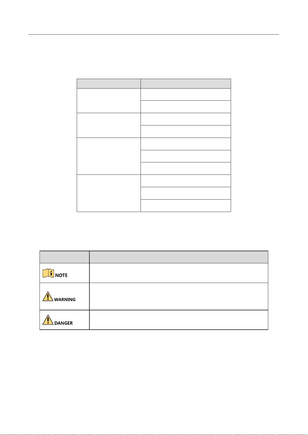
Symbol Conventions
The symbols that may be found in this document are defined as follows.
Symbol
Description
Provides additional information to emphasize or supplement
important points of the main text.
Indicates a potentially hazardous situation, which if not avoided,
could result in equipment damage, data loss, performance
degradation, or unexpected results.
Indicates a hazard with a high level of risk, which if not avoided, will
result in death or serious injury.
Page 5

Network Video Recorder User Manual
4
Safety Instructions
Proper configuration of all passwords and other security settings is the responsibility of the
installer and/or end-user.
In the use of the product, you must be in strict compliance with the electrical safety
regulations of the nation and region. Please refer to technical specifications for detailed
information.
Input voltage should meet both the SELV (Safety Extra Low Voltage) and the Limited Power
Source with 100~240 VAC or 12 VDC according to the IEC60950-1 standard. Please refer to
technical specifications for detailed information.
Do not connect several devices to one power adapter as adapter overload may cause
over-heating or a fire hazard.
Please make sure that the plug is firmly connected to the power socket.
If smoke, odor or noise rise from the device, turn off the power at once and unplug the power
cable, and then please contact the service center.
Preventive and Cautionary Tips
Before connecting and operating your device, please be advised of the following tips:
Ensure unit is installed in a well-ventilated, dust-free environment.
Unit is designed for indoor use only.
Keep all liquids away from the device.
Ensure environmental conditions meet factory specifications.
Ensure unit is properly secured to a rack or shelf. Major shocks or jolts to the unit as a result of
dropping it may cause damage to the sensitive electronics within the unit.
Use the device in conjunction with an UPS if possible.
Power down the unit before connecting and disconnecting accessories and peripherals.
A factory recommended HDD should be used for this device.
Improper use or replacement of the battery may result in hazard of explosion. Replace with
the same or equivalent type only. Dispose of used batteries according to the instructions
provided by the battery manufacturer.
Page 6

Network Video Recorder User Manual
5
TABLE OF CONTENTS
Chapter 1 Introduction ................................................................................................................... 16
1.1 Front Panel ....................................................................................................................... 16
1.2 IR Remote Control Operations ......................................................................................... 16
1.2.1 Pairing (Enabling) the IR Remote to a Specific Device (optional) ........................... 17
1.2.2 Unpairing (Disabling) an IR Remote from a Device ................................................. 18
1.2.3 Troubleshooting ...................................................................................................... 21
1.3 USB Mouse Operation ...................................................................................................... 22
1.4 Rear Panel ........................................................................................................................ 23
1.4.1 DS-7700NXI-I/S Series ............................................................................................. 23
1.4.2 DS-7700NXI-I/P/S Series .......................................................................................... 24
1.4.3 DS-7600NXI-I/S ........................................................................................................ 25
1.4.4 DS-7600NXI-I/P/S .................................................................................................... 26
Chapter 2 Getting Started .............................................................................................................. 27
2.1 Start up the Device ........................................................................................................... 27
2.2 Activate the Device .......................................................................................................... 27
2.3 Configure Unlock Pattern for Login .................................................................................. 28
2.4 Login to the Device ........................................................................................................... 29
2.4.1 Log in via Unlock Pattern ......................................................................................... 29
2.4.2 Log in via Password ................................................................................................. 30
2.5 Enter Wizard to Configure Basic Settings ......................................................................... 31
2.6 Enter Main Menu ............................................................................................................. 35
2.7 System Operation ............................................................................................................. 36
2.7.1 Log out..................................................................................................................... 36
2.7.2 Shut Down the Device ............................................................................................. 36
2.7.3 Reboot the Device ................................................................................................... 37
Chapter 3 Camera Management ................................................................................................... 38
3.1 Add the IP Cameras .......................................................................................................... 38
3.1.1 Add the IP Camera Manually .................................................................................. 38
3.1.2 Add the Automatically Searched Online IP Cameras .............................................. 39
3.2 Manage Cameras for PoE Device ..................................................................................... 39
3.2.1 Add PoE Cameras .................................................................................................... 39
3.2.2 Add Non-PoE IP Cameras ........................................................................................ 39
3.2.3 Configure PoE Interface .......................................................................................... 40
Page 7

Network Video Recorder User Manual
6
3.3 Configure the Customized Protocols ................................................................................ 41
Chapter 4 Camera Settings ............................................................................................................ 43
4.1 Configure OSD Settings ................................................................................................... 43
4.2 Configure Privacy Mask .................................................................................................... 44
4.3 Configure the Video Parameters ...................................................................................... 45
4.4 Configure the Day/Night Switch ....................................................................................... 45
4.5 Configure Other Camera Parameters ............................................................................... 45
Chapter 5 Live View ....................................................................................................................... 47
5.1 Start Live View ................................................................................................................. 47
5.1.1 Digital Zoom ............................................................................................................ 47
5.1.2 3D Positioning ......................................................................................................... 48
5.1.3 Live View Strategy ................................................................................................... 48
5.2 Configure Live View Settings ............................................................................................ 49
5.3 Configure Live View Layout .............................................................................................. 49
5.4 Configure Auto-Switch of Cameras .................................................................................. 51
5.5 Configure Channel-Zero Encoding.................................................................................... 51
5.6 Use an Auxiliary Monitor.................................................................................................. 52
Chapter 6 PTZ Control ................................................................................................................... 53
6.1 PTZ Control Wizard .......................................................................................................... 53
6.2 Configure PTZ Parameters ................................................................................................ 53
6.3 Set PTZ Presets, Patrols & Patterns .................................................................................. 54
6.3.1 Set a Preset .............................................................................................................. 54
6.3.2 Call a Preset ............................................................................................................. 55
6.3.3 Set a Patrol .............................................................................................................. 56
6.3.4 Call a Patrol ............................................................................................................. 57
6.3.5 Set a Pattern ............................................................................................................ 58
6.3.6 Call a Pattern ........................................................................................................... 59
6.3.7 Set Linear Scan Limits .............................................................................................. 59
6.3.8 Call Linear Scan ....................................................................................................... 60
6.3.9 One-touch Park ....................................................................................................... 60
6.4 Auxiliary Functions ........................................................................................................... 61
Chapter 7 Storage ............................................................................................................................ 63
7.1 Storage Device Management ........................................................................................... 63
7.1.1 Install the HDD ........................................................................................................ 63
7.1.2 Add the Network Disk ............................................................................................. 63
Page 8

Network Video Recorder User Manual
7
7.1.3 Configure eSATA for Data Storage ........................................................................... 65
7.2 Storage Mode ................................................................................................................... 66
7.2.1 Configure HDD Group ............................................................................................. 66
7.2.2 Configure HDD Quota .............................................................................................. 68
7.3 Recording Parameters ...................................................................................................... 69
7.3.1 Main Stream ............................................................................................................ 69
7.3.2 Sub-Stream .............................................................................................................. 70
7.3.3 Picture ..................................................................................................................... 70
7.3.4 ANR .......................................................................................................................... 70
7.3.5 Configure Advanced Recording Settings ................................................................. 70
7.4 Configure Recording Schedule ......................................................................................... 71
7.5 Configure Continuous Recording ..................................................................................... 73
7.6 Configure Motion Detection Triggered Recording ........................................................... 73
7.7 Configure Event Triggered Recording ............................................................................... 73
7.8 Configure Alarm Triggered Recording .............................................................................. 74
7.9 Configure POS Event Triggered Recording ....................................................................... 74
7.10 Configure Picture Capture .............................................................................................. 75
7.11 Configure Holiday Recording and Capture ..................................................................... 75
7.12 Configure Redundant Recording and Capture ............................................................... 76
Chapter 8 Disk Array ...................................................................................................................... 78
8.1 Create Disk Array .............................................................................................................. 78
8.1.1 Enable RAID ............................................................................................................. 78
8.1.2 One-Touch Creation ................................................................................................ 79
8.1.3 Manual Creation ...................................................................................................... 79
8.2 Rebuild Array .................................................................................................................... 81
8.2.1 Configure Hot Spare Disk ........................................................................................ 81
8.2.2 Automatically Rebuild Array ................................................................................... 81
8.2.3 Manually Rebuild Array ........................................................................................... 82
8.3 Delete Array ..................................................................................................................... 83
8.4 Check and Edit Firmware ................................................................................................. 83
Chapter 9 File Management .......................................................................................................... 85
9.1 Search and Export Human Files ....................................................................................... 85
9.1.1 Search Human Files ................................................................................................. 85
9.1.2 Export Human Files ................................................................................................. 85
9.2 Search and Export Vehicle Files ....................................................................................... 86
Page 9

Network Video Recorder User Manual
8
9.2.1 Search Vehicle Files ................................................................................................. 86
9.2.2 Export Vehicle Files ................................................................................................. 87
9.3 Search History Operation ................................................................................................. 88
9.3.1 Save Search Condition ............................................................................................. 88
9.3.2 Call Search History................................................................................................... 88
Chapter 10 Playback ....................................................................................................................... 89
10.1 Playing Video Files ......................................................................................................... 89
10.1.1 Instant Playback .................................................................................................... 89
10.1.2 Play Video ............................................................................................................. 89
10.1.3 Play Tag Files ......................................................................................................... 90
10.1.4 Play by Smart Search ............................................................................................. 91
10.1.5 Play Event Files ...................................................................................................... 93
10.1.6 Play by Sub-periods ............................................................................................... 94
10.1.7 Play Log Files ......................................................................................................... 95
10.1.8 Play External File ................................................................................................... 97
10.2 Playback Operations ....................................................................................................... 97
10.2.1 Normal/Important/Custom Video ........................................................................ 97
10.2.2 Set Play Strategy in Important/Custom Mode ...................................................... 97
10.2.3 Edit Video Clips ..................................................................................................... 98
10.2.4 Switch between Main Stream and Sub-Stream .................................................... 98
10.2.5 Thumbnails View................................................................................................... 99
10.2.6 Fast View ............................................................................................................... 99
10.2.7 Digital Zoom .......................................................................................................... 99
Chapter 11 Event and Alarm Settings ........................................................................................ 101
11.1 Configure Arming Schedule .......................................................................................... 101
11.2 Configure Alarm Linkage Actions ................................................................................. 101
11.2.1 Configure Auto-Switch Full Screen Monitoring................................................... 102
11.2.2 Configure Audio Warning .................................................................................... 103
11.2.3 Notify Surveillance Center .................................................................................. 103
11.2.4 Configure Email Linkage ...................................................................................... 103
11.2.5 Trigger Alarm Output .......................................................................................... 103
11.2.6 Configure PTZ Linkage ......................................................................................... 104
11.3 Configure Motion Detection Alarm.............................................................................. 105
11.4 Configure Video Loss Alarm ......................................................................................... 106
11.5 Configure Video Tampering Alarm ............................................................................... 106
Page 10

Network Video Recorder User Manual
9
11.6 Configure Sensor Alarms .............................................................................................. 107
11.6.1 Configure Alarm Input ......................................................................................... 107
11.6.2 Configure One-Key Disarming ............................................................................. 108
11.6.3 Configure Alarm Output ...................................................................................... 109
11.7 Configure Exceptions Alarm ......................................................................................... 111
11.8 Trigger or Clear Alarm Output Manually ...................................................................... 112
Chapter 12 VCA Event Alarm ..................................................................................................... 114
12.1 Human Body Detection ................................................................................................ 114
12.2 Face Detection.............................................................................................................. 115
12.3 Vehicle Detection ......................................................................................................... 116
12.4 Line Crossing Detection ................................................................................................ 117
12.5 Intrusion Detection ...................................................................................................... 119
12.6 Region Entrance Detection .......................................................................................... 121
12.7 Region Exiting Detection .............................................................................................. 122
12.8 Unattended Baggage Detection ................................................................................... 124
12.9 Object Removal Detection ........................................................................................... 125
12.10 Audio Exception Detection ......................................................................................... 126
12.11 Sudden Scene Change Detection ............................................................................... 128
12.12 Defocus Detection ...................................................................................................... 129
12.13 PIR Alarm .................................................................................................................... 129
12.14 Enable Smart Search .................................................................................................. 130
Chapter 13 Smart Search .............................................................................................................. 131
13.1 Face Search ................................................................................................................... 131
13.2 Vehicle Search .............................................................................................................. 131
13.3 People Counting ........................................................................................................... 132
13.4 Heat Map ...................................................................................................................... 132
Chapter 14 Human Body Detection ........................................................................................... 134
14.1 View Engine Status ....................................................................................................... 134
14.2 Human Body Search ..................................................................................................... 134
Chapter 15 POS Configuration .................................................................................................... 135
15.1 Configure POS Settings ................................................................................................. 135
15.1.1 Configure POS Connection .................................................................................. 135
15.1.2 Configure POS Text Overlay ................................................................................. 139
15.2 Configure POS Alarm .................................................................................................... 141
Chapter 16 Network Settings ...................................................................................................... 142
Page 11

Network Video Recorder User Manual
10
16.1 Configure TCP/IP Settings ............................................................................................. 142
16.2 Configuring Hik-Connect .............................................................................................. 143
16.3 Configure DDNS ............................................................................................................ 145
16.4 Configure PPPoE ........................................................................................................... 146
16.5 Configure NTP .............................................................................................................. 146
16.6 Configure SNMP ........................................................................................................... 147
16.7 Configure Email ............................................................................................................ 148
16.8 Configure Ports ............................................................................................................. 150
Chapter 17 Hot Spare Device Backup ........................................................................................ 152
17.1 Set Hot Spare Device .................................................................................................... 152
17.2 Set Working Device ...................................................................................................... 153
17.3 Manage Hot Spare System ........................................................................................... 153
Chapter 18 System Maintenance ................................................................................................. 155
18.1 Storage Device Maintenance ....................................................................................... 155
18.1.1 Configure Disk Clone ........................................................................................... 155
18.1.2 S.M.A.R.T Detection ............................................................................................ 156
18.1.3 Bad Sector Detection .......................................................................................... 157
18.1.4 HDD Health Detection ......................................................................................... 158
18.2 Search & Export Log Files ............................................................................................. 159
18.2.1 Search the Log Files ............................................................................................. 159
18.2.2 Export the Log Files ............................................................................................. 161
18.3 Import/Export IP Camera Configuration Files .............................................................. 162
18.4 Import/Export Device Configuration Files ................................................................... 164
18.5 Upgrade System ........................................................................................................... 165
18.5.1 Upgrade by Local Backup Device ......................................................................... 165
18.5.2 Upgrade by FTP ................................................................................................... 165
18.6 Restore Default Settings ............................................................................................... 167
18.7 System Service.............................................................................................................. 167
18.7.1 Network Security Settings ................................................................................... 167
18.7.2 Manage ONVIF User Accounts ............................................................................ 169
18.7.3 Manage IP Camera Activation ............................................................................. 170
Chapter 19 General System Settings........................................................................................... 172
19.1 Configure General Settings .......................................................................................... 172
19.2 Configure Date & Time ................................................................................................ 173
19.3 Configure DST Settings ................................................................................................. 174
Page 12

Network Video Recorder User Manual
11
19.4 Manage User Accounts................................................................................................. 174
19.4.1 Add a User ........................................................................................................... 174
19.4.2 Set the Permission for a User .............................................................................. 176
19.4.3 Set Local Live View Permission for Non-Admin Users ........................................ 178
19.4.4 Edit the Admin User ............................................................................................ 179
19.4.5 Edit the Operator/Guest User ............................................................................. 181
19.4.6 Delete a User ....................................................................................................... 182
Chapter 20 Appendix ................................................................................................................... 183
20.1 Glossary ........................................................................................................................ 183
20.2 Troubleshooting ........................................................................................................... 185
Page 13

Network Video Recorder User Manual
12
Product Key Features
General
Connectable to network cameras, network dome and encoders.
Connectable to the third-party network cameras like ACTI, Arecont, AXIS, Bosch, Brickcom,
Canon, PANASONIC, Pelco, SAMSUNG, SANYO, SONY, Vivotek and ZAVIO, and cameras that
adopt ONVIF protocol.
Connectable to the smart IP cameras.
H.265+/H.265/ H.264+/H.264/MPEG4 video formats
PAL/NTSC adaptive video inputs.
Each channel supports dual-stream.
Up to 64 network cameras can be added according to different models.
Independent configuration for each channel, including resolution, frame rate, bit rate, image
quality, etc.
The quality of the input and output record is configurable.
Local Monitoring
HDMI/VGA output provided.
HDMI Video output at up to 4K resolution and VGA video output at up to 2K resolution.
Multiple screen display in live view is supported, and the display sequence of channels is
adjustable.
Live view screen can be switched in group. Manual switch and auto-switch are provided and
the auto-switch interval is configurable.
3D positioning in live view.
Configurable main stream and sub-stream for the live view.
Quick setting menu is provided for live view.
POS information overlay on live view.
Motion detection, video tampering, video exception alert and video loss alert functions.
Privacy mask.
Multiple PTZ protocols supported; PTZ preset, patrol and pattern.
Zooming in by clicking the mouse and PTZ tracing by dragging mouse.
HDD Management
Up to 4 SATA hard disks and 1 eSATA disk can be connected.
Supports 8 network disks (NAS/IP SAN disk).
Supports S.M.A.R.T. and bad sector detection.
HDD group management.
Page 14

Network Video Recorder User Manual
13
Supports HDD standby function.
HDD property: redundancy, read-only, read/write (R/W).
HDD quota management; different capacity can be assigned to different channel.
RAID0, RAID1, RAID5, RAID6 and RAID 10 are supported.
Hot-swappable RAID storage scheme, and can be enabled and disabled on your demand. And
16 arrays can be configured.
Supports disk clone to the eSATA disk.
Recording, Capture and Playback
Holiday recording schedule configuration.
Continuous and event video recording parameters.
Multiple recording types: manual, continuous, alarm, motion, motion | alarm, motion & alarm
VCA, and POS.
8 recording time periods with separated recording types.
POS information overlay on image.
Pre-record and post-record for alarm, motion detection for recording, and pre-record time for
schedule and manual recording.
Searching record files and captured pictures by events (alarm input/motion detection).
Tag adding for record files, searching and playing back by tags.
Locking and unlocking record files.
Local redundant recording and capture.
Provide new playback interface with easy and flexible operation.
Searching and playing back record files by channel number, recording type, start time, end
time, etc.
Supports the playback by main stream or sub stream.
Smart search for the selected area in the video.
Zooming in when playback.
Reverse playback of multi-channel.
Supports pause, play reverse, speed up, speed down, skip forward, and skip backward when
playback, and locating by dragging the mouse.
Supports thumbnails view and fast view during playback.
Up to 12-ch synchronous playback at 1080p real time.
Supports playback by transcoded stream.
Manual capture, continuous capture of video images and playback of captured pictures.
Supports enabling H.264+ to ensure high video quality with lowered bitrate.
Backup
Export video data by USB, SATA or eSATA device.
Page 15

Network Video Recorder User Manual
14
Export video clips when playback.
Management and maintenance of backup devices.
Either Normal or Hot Spare working mode is configurable to constitute an N+1 hot spare
system.
Human Body Detection
Human body detection and alarm linkage actions.
More precise human body analytics based on deep learning algorithm.
Re-recognition of the human body target in behavior analytics (line crossing detection,
intrusion detection) to effectively raise the alarm accuracy rate.
Alarm and Exception
Configurable arming time of alarm input/output.
Alarm for video loss, motion detection, tampering, abnormal signal, video input/output
standard mismatch, illegal login, network disconnected, IP confliction, abnormal
record/capture, HDD error, and HDD full, etc.
POS triggered alarm supported.
VCA detection alarm is supported.
VCA search for face detection vehicle plate, behavior analysis, people counting and heat map.
Only DS-7700NXI series support face detection function.
Connectable to the thermal network camera.
Supports the advanced search for fire/ship/temperature/temperature difference detection
triggered alarm and the recorded video files and pictures.
Alarm triggers full screen monitoring, audio alarm, notifying surveillance center, sending email
and alarm output.
Automatic restore when system is abnormal.
Other Local Functions
Operable by front panel, mouse, remote control, or control keyboard.
Three-level user management; admin user is allowed to create many operating accounts and
define their operating permission, which includes the limit to access any channel.
Admin password resetting by exporting/importing the GUID file.
Operation, alarm, exceptions and log recording and searching.
Manually triggering and clearing alarms.
Import and export of device configuration information.
Network Functions
Page 16

Network Video Recorder User Manual
15
Two self-adaptive 10M/100M/1000Mbps network interfaces, and the multi-address and
network fault tolerance working modes are configurable.
IPv6 is supported.
TCP/IP protocol, DHCP, DNS, DDNS, NTP, SADP, SMTP, SNMP, NFS, and iSCSI are supported.
TCP, UDP and RTP for unicast.
Auto/Manual port mapping by UPnP
TM
.
Remote web browser access by HTTPS ensures high security.
The ANR (Automatic Network Replenishment) function is supported, it enables the IP camera
save the recording files in the local storage when the network is disconnected, and
synchronizes the files to the NVR when the network is resumed.
Remote reverse playback via RTSP.
Supports accessing by the platform via ONVIF.
Remote search, playback, download, locking and unlocking of the record files, and support
downloading files broken transfer resume.
Remote parameters setup; remote import/export of device parameters.
Remote viewing of the device status, system logs and alarm status.
Remote keyboard operation.
Remote HDD formatting and program upgrading.
Remote system restart and shutdown.
RS-232, RS-485 transparent channel transmission.
Alarm and exception information can be sent to the remote host
Remotely start/stop recording.
Remotely start/stop alarm output.
Remote PTZ control.
Remote JPEG capture.
Virtual host function is provided to get access and manage the IP camera directly.
Two-way audio and voice broadcasting.
Embedded WEB server.
Development Scalability:
SDK for Windows system.
Source code of application software for demo.
Development support and training for application system.
Page 17
Network Video Recorder User Manual
16
Chapter 1 Introduction
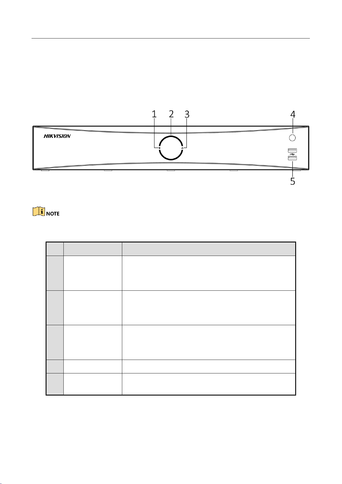
1.1 Front Panel
Figure 1-1 Front Panel
The DS-7600NXI series only have one USB 2.0 port.
Table 1-1 Panel Description
1.2 IR Remote Control Operations
The device may also be controlled with the included IR remote control, shown in Figure 1-2.
No.
Name
Function Description
1
HDD indicator
Solid white: HDD is abnormal.
Flashing white: HDD is reading/writing.
Unlit: No HDD is detected.
2
Power indicator
Solid white: Device is running normally.
Breathing light: Device is shutdown.
Unlit: No power supply is connected.
3
Network indicator
Solid white: Network connection is normal.
Flashing white: Device is transferring data via network.
Unlit: Network connection failed.
4
IR receiver
IR receiver for remote control.
5
USB
Universal Serial Bus (USB) 2.0 port for additional devices
such as USB mouse and USB Hard Disk Drive (HDD).
Page 18

Network Video Recorder User Manual
17
Batteries (2×AAA) must be installed before operation.
The IR remote is set at the factory to control the device (using default Device ID# 255) without any
additional steps. Device ID# 255 is the default universal device identification number shared by the
devices. You may also pair an IR Remote to a specific device by changing the Device ID#, as follows:
1.2.1 Pairing (Enabling) the IR Remote to a Specific Device (optional)
You can pair an IR Remote to a specific device by creating a user-defined Device ID#. This feature is
useful when using multiple IR Remotes and devices.
On the device:
Step 1 Go to System > General.
Step 2 Type a number (255 digits maximum) into the Device No. field.
On the IR Remote:
Step 3 Press the DEV button.
Step 4 Use the Number buttons to enter the Device ID# that was entered into the device.
Step 5 Press Enter button to accept the new Device ID#.
Page 19
Network Video Recorder User Manual
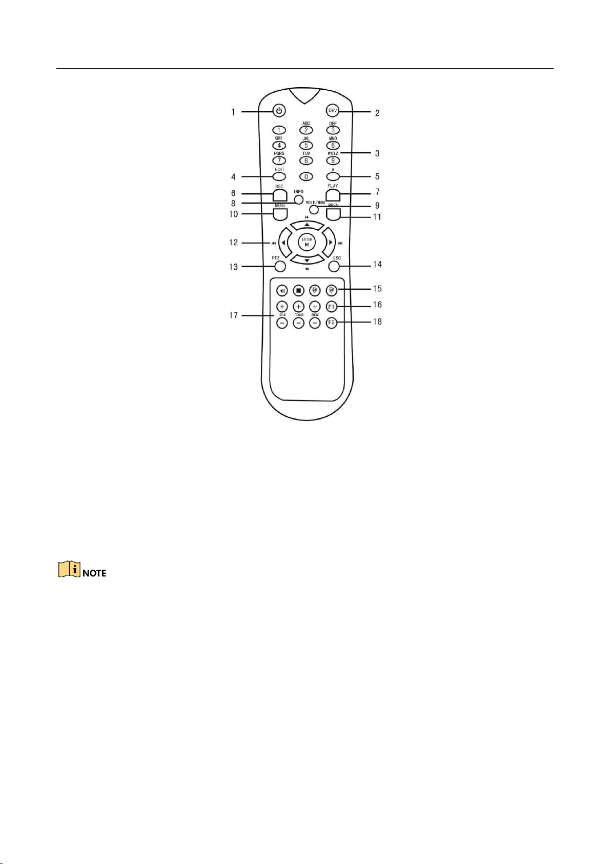
18
Figure 1-2 Remote Control
1.2.2 Unpairing (Disabling) an IR Remote from a Device
To unpair an IR Remote from a device so that the unit cannot control any device functions, proceed
as follows:
Press the DEV key on the IR Remote. Any existing Device ID# will be erased from the unit’s memory
and it will no longer function with the device.
(Re)-enabling the IR Remote requires pairing to a device. See “Pairing the IR Remote to a Specific
device (optional),” above.
The keys on the remote control closely resemble the ones on the front panel. See the table 1.4.
Page 20

Network Video Recorder User Manual
19
Table 1-2 IR Remote Functions
No.
Name
Function Description
1
POWER
ON/OFF
•To Turn Power On:
-If User Has Not Changed the Default device Device ID# (255):
1.Press Power On/Off button (1).
-If User Has Changed the device Device ID#:
1.Press DEV button.
2.Press Number buttons to enter user-defined Device ID#.
3.Press Enter button.
4.Press Power button to start device.
•To Turn device Off:
-If User Is Logged On:
1.Hold Power On/Off button (1) down for five seconds to display
the “Yes/No” verification prompt.
2.Use Up/Down Arrow buttons (12) to highlight desired selection.
3.Press Enter button (12) to accept selection.
-If User Is Not Logged On:
1.Hold Power On/Off button (1) down for five seconds to display
the user name/password prompt.
2.Press the Enter button (12) to display the on-screen keyboard.
3.Input the user name.
4.Press the Enter button (12) to accept input and dismiss the
on-screen keyboard.
5.Use the Down Arrow button (12) to move to the “Password”
field.
6.Input password (use on-screen keyboard or numeric buttons (3)
for numbers).
7.Press the Enter button (12) to accept input and dismiss the
on-screen keyboard.
8.Press the OK button on the screen to accept input and display
the Yes/No” verification prompt (use Up/Down Arrow buttons (12)
to move between fields)
9.Press Enter button (12) to accept selection.
User name/password prompt depends on device is configuration.
Page 21

Network Video Recorder User Manual
20
See “System Configuration” section.
2
DEV
Enable IR Remote: Press DEV button, enter device Device ID# with
number keys, press Enter to pair unit with the device
Disable IR Remote: Press DEV button to clear Device ID#; unit will
no longer be paired with the device
3
Numerals
Switch to the corresponding channel in Live View or PTZ Control
mode
Input numbers in Edit mode
4
EDIT
Delete characters before cursor
Check the checkbox and select the ON/OFF switch
5
A
Adjust focus in the PTZ Control menu
Switch on-screen keyboards (upper and lower case alphabet,
symbols, and numerals)
6
REC
Enter Manual Record setting menu
Call a PTZ preset by using the numeric buttons in PTZ control
settings
Turn audio on/off in Playback mode
7
PLAY
Go to Playback mode
Auto scan in the PTZ Control menu
8
INFO
Reserved
9
VOIP
Switches between main and spot output
Zooms out the image in PTZ control mode
10
MENU
Return to Main menu (after successful login)
N/A
Show/hide full screen in Playback mode
12
DIRECTION
Navigate between fields and menu items
Use Up/Down buttons to speed up/slow down recorded video, and
Left/Right buttons to advance/rewind 30 secs in Playback mode
Cycle through channels in Live View mode
Control PTZ camera movement in PTZ control mode
ENTER
Confirm selection in any menu mode
Page 22

Network Video Recorder User Manual
21
Checks checkbox
Play or pause video in Playback mode
Advance video a single frame in single-frame Playback mode
Stop/start auto switch in auto-switch mode
13
PTZ
Enter PTZ Control mode
14
ESC
Go back to previous screen
N/A
15
RESERVED
Reserved
16
F1
Select all items on a list
N/A
Switch between play and reverse play in Playback mode
17
PTZ Control
Adjust PTZ camera iris, focus, and zoom
18
F2
Cycle through tab pages
Switch between channels in Synchronous Playback mode
1.2.3 Troubleshooting
Make sure you have installed batteries properly in the remote control. And you have to aim the
remote control at the IR receiver in the front panel.
If there is no response after you press any button on the remote, follow the procedure below to
troubleshoot.
Step 1 Go to System > General by operating the front control panel or the mouse.
Step 2 Check and remember device ID#. The default ID# is 255. This ID# is valid for all the IR remote
controls.
Step 3 Press the DEV button on the remote control.
Step 4 Enter the device ID# you set in step 2.
Step 5 Press the ENTER button on the remote.
If the Status indicator on the front panel turns blue, the remote control is operating properly. If
the Status indicator does not turn blue and there is still no response from the remote, please
check the following:
Batteries are installed correctly and the polarities of the batteries are not reversed.
Page 23

Network Video Recorder User Manual
22
Batteries are fresh and not out of charge.
IR receiver is not obstructed.
No fluorescent lamp is used nearby
If the remote still can’t function properly, please change a remote and try again, or contact the
device provider.
1.3 USB Mouse Operation
A regular 3-button (Left/Right/Scroll-wheel) USB mouse can also be used with this device. To use a
USB mouse:
Step 1 Plug USB mouse into one of the USB interfaces on the front panel of the device.
Step 2 The mouse should automatically be detected. If in a rare case that the mouse is not detected,
the possible reason may be that the two devices are not compatible, please refer to the
recommended the device list from your provider.
The operation of the mouse:
Table 1-3 Description of the Mouse Control
Name
Action
Description
Left-Click
Single-Click
Live view: Select channel and show the quick set
menu.
Menu: Select and enter.
Double-Click
Live view: Switch between single-screen and
multi-screen.
Click and Drag
PTZ control: pan, tilt and zoom.
Video tampering, privacy mask and motion
detection: Select target area.
Digital zoom-in: Drag and select target area.
Live view: Drag channel/time bar.
Right-Click
Single-Click
Live view: Show menu.
Menu: Exit current menu to upper level menu.
Scroll-Wheel
Scrolling up
Live view: Previous screen.
Menu: Previous item.
Scrolling
down
Live view: Next screen.
Menu: Next item.
Page 24

Network Video Recorder User Manual
23
1.4 Rear Panel
1.4.1 DS-7700NXI-I/S Series
Figure 1-3 Rear Panel
Table 1-4 Panel Description
No.
Name
Description
1
eSATA
Connects external SATA HDD, CD/DVD-RM.
2
Audio in
RCA connector for audio input.
3
Video out
CVBS video output.
4
RS-232
Connector for RS-232 device.
5
Power supply
100 to 240 VAC power supply
6
LAN1/LAN2
2 RJ-45 10/100/1000 Mbps self-adaptive Ethernet
interfaces.
7
Audio out
RCA connector for audio output.
8
HDMI
HDMI video output connector.
9
USB 3.0
Universal Serial Bus (USB) 3.0 port for additional device
such as USB mouse and USB Hard Disk Drive (HDD).
10
VGA
DB9 connector for VGA output. Display local video output
and menu.
11
RS-485
Connector for RS-485 device.
12
Controller Port
D+, D- pin connects to Ta, Tb pin of controller. For
cascading devices, the first NVR’s D+, D- pin should be
connected with the D+, D- pin of the next NVR.
13
Alarm In/out
Connector for alarm input/output.
14
GND
Ground.
15
Power switch
Switch for turning on/off the device.
Page 25

Network Video Recorder User Manual
24
1.4.2 DS-7700NXI-I/P/S Series
Figure 1-4 Rear Panel
Table 1-5 Panel Description
No.
Name
Description
1
Video out
CVBS video output.
2
eSATA
Connects external SATA HDD, CD/DVD-RM.
3
RS-232
Connector for RS-232 device.
4
Audio in
RCA connector for audio input.
5
VGA
DB9 connector for VGA output. Display local video output
and menu.
6
Power supply
100 to 240 VAC power supply
7
PoE
RJ-45 10/100 Mbps self-adaptive Ethernet interfaces.
8
LAN
1 RJ-45 10/100/1000 Mbps self-adaptive Ethernet
interface.
9
USB 3.0
Universal Serial Bus (USB) 3.0 port for additional device
such as USB mouse and USB Hard Disk Drive (HDD).
10
Audio out
RCA connector for audio output.
11
HDMI
HDMI video output connector.
12
RS-485
Connector for RS-485 device.
13
Controller Port
D+, D- pin connects to Ta, Tb pin of controller. For
cascading devices, the first NVR’s D+, D- pin should be
connected with the D+, D- pin of the next NVR.
14
Alarm In/out
Connector for alarm input/output.
15
GND
Ground.
16
Power switch
Switch for turning on/off the device.
Page 26

Network Video Recorder User Manual
25
1.4.3 DS-7600NXI-I/S
Figure 1-5 Rear Panel
Table 1-6 Panel Description
No.
Name
Description
1
Audio out
RCA connector for audio output.
2
Audio in
RCA connector for audio input.
3
VGA
DB9 connector for VGA output. Display local video output
and menu.
4
Alarm in/out
Connector for alarm input/output.
5
HDMI
HDMI video output connector.
6
USB 3.0
Universal Serial Bus (USB) 3.0 port for additional device
such as USB mouse and USB Hard Disk Drive (HDD).
7
LAN
1 RJ-45 10/100/1000 Mbps self-adaptive Ethernet
interface.
8
Power supply
12 VDC power supply
9
GND
Ground.
10
Power switch
Switch for turning on/off the device.
11
Video out
CVBS video output.
Page 27

Network Video Recorder User Manual
26
1.4.4 DS-7600NXI-I/P/S
Figure 1-6 Rear Panel
Table 1-7 Panel Description
No.
Name
Description
1
PoE
RJ-45 10/100 Mbps self-adaptive Ethernet interfaces.
2
Audio out
RCA connector for audio output.
3
Audio in
RCA connector for audio input.
4
VGA
DB9 connector for VGA output. Display local video output
and menu.
5
Alarm in/out
Connector for alarm input/output.
6
HDMI
HDMI video output connector.
7
USB 3.0
Universal Serial Bus (USB) 3.0 port for additional device
such as USB mouse and USB Hard Disk Drive (HDD).
8
LAN
1 RJ-45 10/100/1000 Mbps self-adaptive Ethernet
interface.
9
Video out
CVBS video output.
10
GND
Ground.
11
Power supply
100 to 240 VAC power supply
Page 28

Network Video Recorder User Manual
27
Chapter 2 Getting Started
2.1 Start up the Device
Purpose
Proper startup and shutdown procedures are crucial to expanding the life of the device.
Before you start
Check that the voltage of the extra power supply is the same with the device’s requirement, and
the ground connection is working properly.
Step 1 Connect the device power supply interface and electrical socket with delivered power cable. It
is HIGHLY recommended that an Uninterruptible Power Supply (UPS) be used in conjunction
with the device. The Power button on the front panel should be red, indicating the device is
receiving the power.
2.2 Activate the Device
Purpose:
For the first-time access, you need to activate the device by setting an admin password. No
operation is allowed before activation. You can also activate the device via Web Browser, SADP or
Client Software.
Step 1 Input the same password in the text field of Create New Password and Confirm New Password.
You can click to show the characters input.
Figure 2-1 Activating the Device
Page 29

Network Video Recorder User Manual
28
We highly recommend you create a strong password of your own choosing (Using a minimum of 8
characters, including at least three of the following categories: upper case letters, lower case
letters, numbers, and special characters.) in order to increase the security of your product. And we
recommend you reset your password regularly, especially in the high security system, resetting the
password monthly or weekly can better protect your product.
Step 2 In the Create Channel Default Password text field, create a login password for IP camera (s)
connected to the device.
Step 3 (Optional) Check Export GUID and Security Question Configuration.
Export GUID: export the GUID for future password resetting.
Security Question Configuration: configure the security questions which can be used for
resetting the password.
Step 4 Click OK.
What to do next:
When you have enabled the Export GUID, continue to export the GUID file to the USB flash
driver for the future password resetting.
When you have enabled the Security Question Configuration, continue to set the security
questions for the future password resetting.
After the device is activated, you should properly keep the password.
You can duplicate the password to the IP cameras that are connected with default protocol.
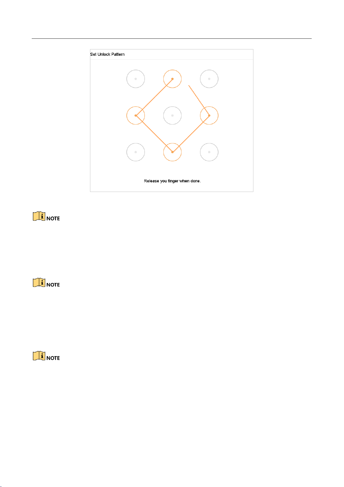
2.3 Configure Unlock Pattern for Login
For the admin user, you can configure the unlock pattern for device login.
Step 1 After the device is activated, you can enter the following interface to configure the device
unlock pattern.
Step 2 Use the mouse to draw a pattern among the 9 dots on the screen. Release the mouse when the
pattern is done.
Page 30
Network Video Recorder User Manual
29
Figure 2-2 Draw the Pattern
Connect at least 4 dots to draw the pattern.
Each dot can be connected for once only.
Step 3 Draw the same pattern again to confirm it. When the two patterns match, the pattern is
configured successfully.
If the two patterns are different, you must set the pattern again.
2.4 Login to the Device
2.4.1 Log in via Unlock Pattern
Only the admin user has the permission to unlock the device.
Please configure the pattern first before unlocking. Please refer to Chapter 2.3 Configure
Unlock Pattern for Login.
Step 1 Right click the mouse on the screen and select the menu to enter the interface.
Page 31

Network Video Recorder User Manual
30
Figure 2-3 Draw the Unlock Pattern
Step 2 Draw the pre-defined pattern to unlock to enter the menu operation.
If you have forgotten your pattern, you can select the Forgot My Pattern or Switch User
option to enter the normal login dialog box.
When the pattern you draw is different from the pattern you have configured, you should
try again.
If you have drawn the wrong pattern for more than 5 times, the system will switch to the
normal login mode automatically.
2.4.2 Log in via Password
Purpose:
If device has logged out, you must login the device before operating the menu and other functions.
Step 1 Select the User Name in the dropdown list.
Page 32

Network Video Recorder User Manual
31
Figure 2-4 Login Interface
Step 2 Input password.
Step 3 Click OK to log in.
When you forget the password of the admin, you can click Forgot Password to reset the
password.
In the Login dialog box, if you enter the wrong password 7 times, the current user account
will be locked for 60 seconds.
2.5 Enter Wizard to Configure Basic Settings
By default, the Setup Wizard starts once the device has loaded.
The Setup Wizard can walk you through some important settings of the device. If you don’t want
to use the Setup Wizard at that moment, click the Exit button.
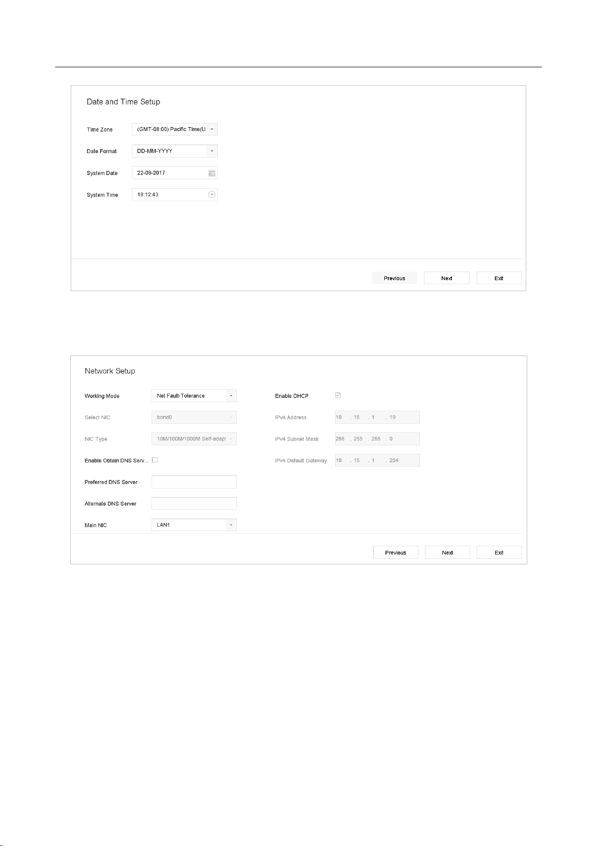
Step 1 Configure the date and time on the Date and Time Setup interface.
Page 33
Network Video Recorder User Manual
32
Figure 2-5 Date and Time Settings
Step 2 After the time settings, click Next to enter the Network Setup Wizard window, as shown in the
following figure.
Figure 2-6 Network Settings
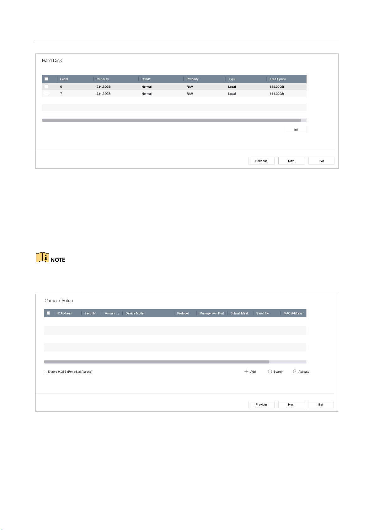
Step 3 Click Next after you configured the network parameters, which takes you to the HDD
Management window.
Page 34
Network Video Recorder User Manual
33
Figure 2-7 HDD Management
Step 4 To initialize the HDD, click the Init button. Initialization removes all the data saved in the HDD.
Step 5 Click Next. You enter the Camera Setup interface to add the IP cameras.
1) Click Search to search the online IP Camera. Before adding the camera, make sure the IP
camera to be added is in active status.
2) Click the Add to add the camera.
If the camera is in inactive status, you can select the camera from the list and click Activate to
activate the cameras.
Figure 2-8 Search for IP Cameras
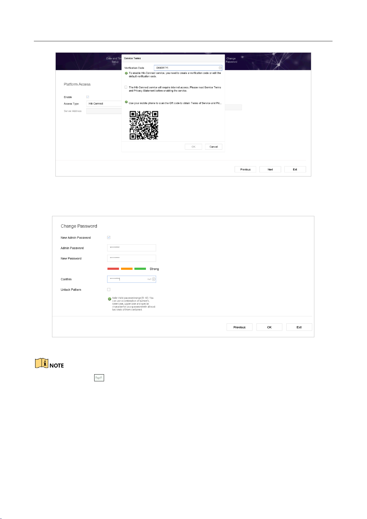
Step 6 Enter the Platform Access and configure the Hik-Connect settings.
Page 35
Network Video Recorder User Manual
34
Figure 2-9 Hik-Connect Access
Step 7 Click Next to enter the Change Password interface to create the new admin password if
required.
Figure 2-10 Change Password
You can enter click to show the characters input.
1) Check the checkbox of New Admin Password.
2) Enter the original password in the text field of Admin Password
3) Input the same password in the text field of New Password and Confirm.
4) Check the Unlock Pattern to enable the unlock pattern login.
Page 36

Network Video Recorder User Manual
35
We highly recommend you create a strong password of your own choosing (Using a minimum of 8
characters, including at least three of the following categories: upper case letters, lower case
letters, numbers, and special characters.) in order to increase the security of your product. And we
recommend you reset your password regularly, especially in the high security system, resetting the
password monthly or weekly can better protect your product.
Step 8 Click OK to complete the startup Setup Wizard.
2.6 Enter Main Menu
After you have completed the wizard, you can right click on the screen to pop up main menu bar.
Refer to the following figure and table for the description of main menu and sub-menus.
Figure 2-11 Main Menu Bar
Table 2-1 Description of Icons
Icon
Description
Live View
Playback
File Management
Smart Analysis
Camera Management
Storage Management
System Management
Page 37
Network Video Recorder User Manual
36
System Maintenance:
2.7 System Operation
2.7.1 Log out
Purpose:
After logging out, the monitor turns to the live view mode and if you want to perform any
operations, you need to enter user name and password to log in again.
Step 1 Click on the menu bar.
Figure 2-12 Logout
Step 2 Click Logout.
After you have logged out the system, menu operation on the screen is invalid. It is required to
input a user name and password to unlock the system.
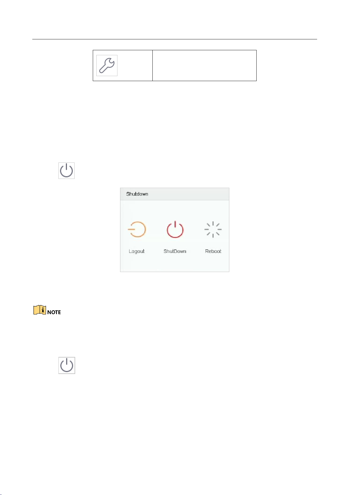
2.7.2 Shut Down the Device
Step 1 Click on the menu bar.
Page 38

Network Video Recorder User Manual
37
Figure 2-13 Shutdown Menu
Step 2 Click the Shutdown button.
Step 3 Click the Yes button.
Do not press the POWER button again when the system is shutting down.
2.7.3 Reboot the Device
From the Shutdown menu, you can also reboot the device.
Step 1 Click on the menu bar.
Step 2 Click Reboot to reboot the device.
Page 39

Network Video Recorder User Manual
38
Chapter 3 Camera Management
3.1 Add the IP Cameras
3.1.1 Add the IP Camera Manually
Purpose:
Before you can get live video or record the video files, you should add the network cameras to the
connection list of the device.
Before you start:
Ensure the network connection is valid and correct, and the IP camera to add has already been
activated.
Step 1 Click on the main menu bar to enter the Camera Management.
Step 2 Click the Custom Add tab on the title bar to enter the Add IP Camera interface.
Figure 3-1 Add IP Camera
Step 3 Enter IP address, protocol, management port, and other information of the IP camera to add.
Step 4 Enter the login user name and password of the IP camera.
Step 5 Click Add to finish the adding of the IP camera.
Page 40

Network Video Recorder User Manual
39
Step 6 (Optional) Click Continue to Add to continue to add other IP cameras.
3.1.2 Add the Automatically Searched Online IP Cameras
Step 1 On the Camera Management interface, click the Online Device panel to expand the Online
Device interface.
Step 2 Select the automatically searched online devices.
Step 3 Click Add.
If the IP camera to add has not been actiavated, you can activate it from the IP camera list on the
camera management interface.
3.2 Manage Cameras for PoE Device
This chapter is only applicable for the following models: DS-7700NXI-I/P/S series device.
Purpose:
The PoE interfaces enables the device system to pass electrical power safely, along with data, on
Ethernet cabling to the connected PoE cameras. Supported PoE camera number varies with device
model
If you disable the PoE interface, you can also connect to the online network cameras. And the PoE
interface supports the Plug-and-Play function.
For example, for iDS-7716NXI-I4/16P/8S, if you want to connect 8 network cameras via PoE
interfaces and 8 online cameras, you must disable 8 PoE interfaces in the Edit IP Camera menu.
Follow the steps to add network cameras for device supporting PoE function.
3.2.1 Add PoE Cameras
Step 1 Connect PoE cameras to device PoE ports with network cables.
Step 2 Go to Camera > Camera > IP Camera to view camera image and information.
3.2.2 Add Non-PoE IP Cameras
You can disable the PoE interface by selecting the manual while the current channel can be used as
a normal channel and the parameters can also be edited.
Step 1 Go to Camera > Camera > IP Camera.
Page 41

Network Video Recorder User Manual
40
Step 2 Position the cursor on a window with no linked IP camera and click the button.
Figure 3-2 Edit IP Camera
Step 3 Select Adding Method as Manual.
• Plug-and-Play: The camera is physically connected to the PoE interface. Its parameters
cannot be edited. You can go to System > Network > TCP/IP to change IP address of PoE
port. .
• Manual: Add IP camera without physical connection via network.
Step 4 Enter the IP address, the user name and password of administrator manually.
Step 5 Click OK.
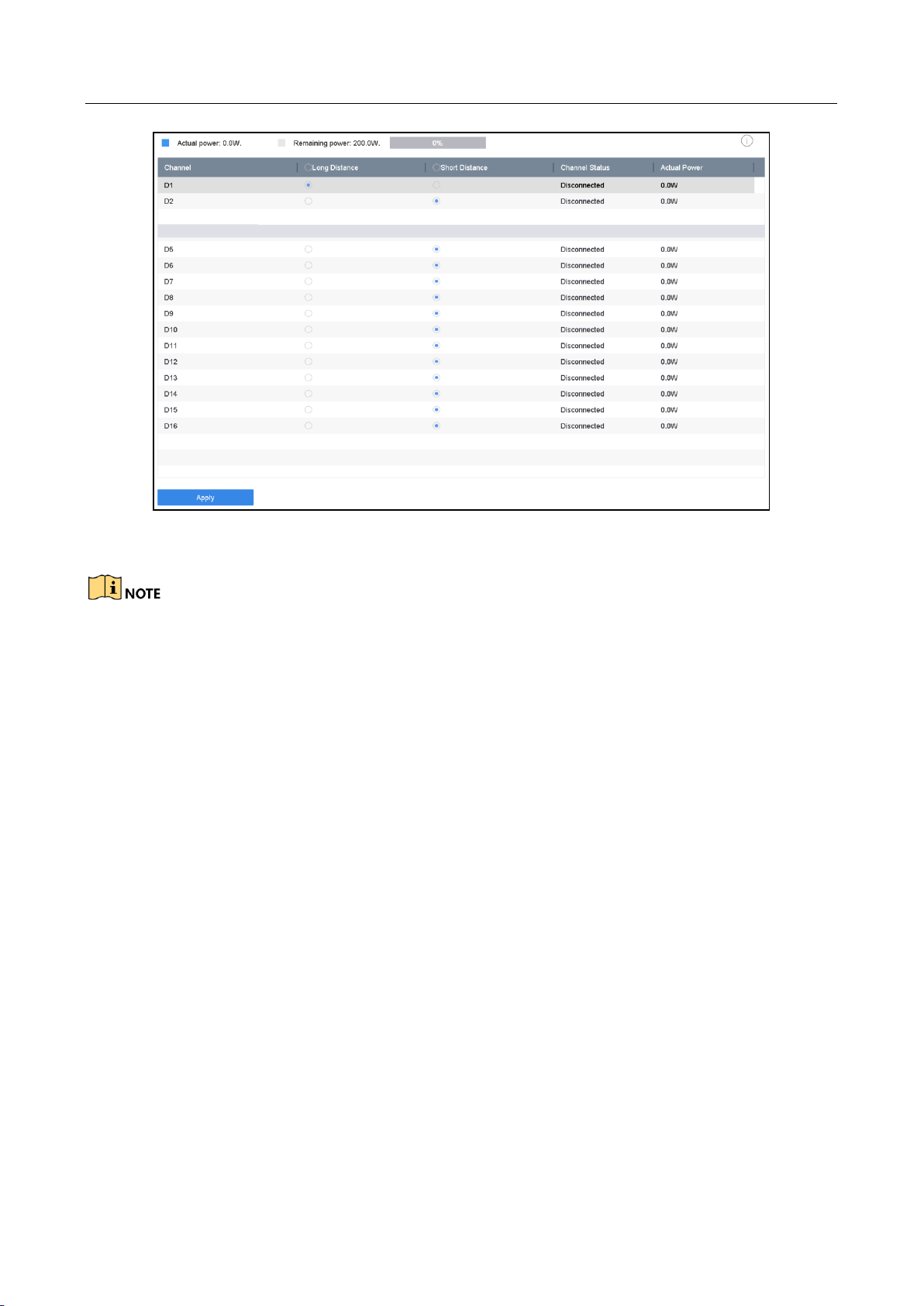
3.2.3 Configure PoE Interface
Purpose:
When it requires long-distance PoE transmission (100 to 300 m), you can enable long distance
mode for the PoE channel.
Step 1 Go to Camera > Camera >PoE Settings.
Step 2 Enable or disable long network cable mode by selecting Long Distance or Short Distance
radio.
Long Distance: Long-distance (100 to 300 meters) network transmissions via PoE interface.
Short Distance: Short-distance (< 100 meters) network transmission via PoE interface.
Page 42
Network Video Recorder User Manual
41
Figure 3-3 PoE Settings
The PoE ports are enabled with the short distance mode by default.
The bandwidth of IP camera connected to the PoE via long network cable (100 to 300
meters) cannot exceed 6 MP.
The allowed max. long network cable may be less than 300 meters depending on different
IP camera models and cable materials.
When the transmission distance reaches 100 to 250 meters, you must use the CAT5E or
CAT6 network cable to connect with the PoE interface.
When the transmission distance reaches 250 to 300 meters, you must use the CAT6
network cable to connect with the PoE interface.
Step 3 Click Apply.
3.3 Configure the Customized Protocols
Purpose:
To connect the network cameras which are not configured with the standard protocols, you can
configure the customized protocols for them. The system provides 16 customized protocols.
Step 1 Click Protocol at the top taskbar to enter the protocol management interface.
Page 43

Network Video Recorder User Manual
42
Figure 3-4 Protocol Management
Step 2 Select the protocol type of transmission and choose the transfer protocols.
Type: The network camera adopting custom protocol must support getting stream through
standard RTSP.
Path: you have to contact the manufacturer of the network camera to consult the URL
(uniform resource locator) for getting main stream and sub-stream.
The format of the URL is: [Type]://[IP Address of the network camera]:[Port]/[Path].
Example: rtsp://192.168.1.55:554/ch1/main/av_stream.
The protocol type and the transfer protocols must be supported by the connected IP camera.
Result:
Step 3 After adding the customized protocols, you can see the protocol name is listed in the
drop-down list.
Page 44

Network Video Recorder User Manual
43
Chapter 4 Camera Settings
4.1 Configure OSD Settings
Purpose:
You can configure the OSD (On-screen Display) settings for the camera, including date/time,
camera name, etc.
Step 1 Go to Camera > Display.
Step 2 Select the camera from the drop-down list.
Step 3 Edit the name in the Camera Name text field.
Step 4 Check the checkbox of the Display Name, Display Date and Display Week if you want to show
the information on the image.
Step 5 Set the date format, time format, and display mode.
Figure 4-1 OSD Configuration Interface
Step 6 You can use the mouse to click and drag the text frame on the preview window to adjust the
OSD position.
Step 7 Click the Apply button to apply the settings.
Page 45
Network Video Recorder User Manual
44
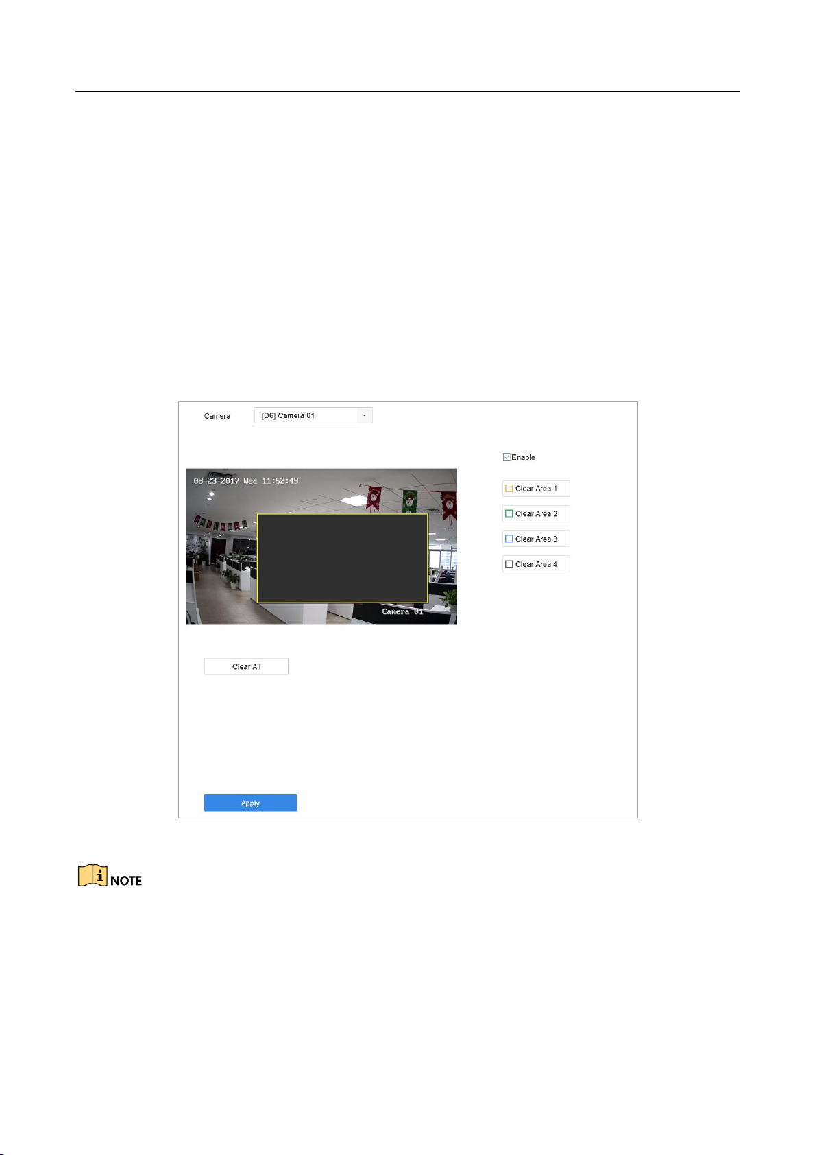
4.2 Configure Privacy Mask
Purpose:
The privacy mask can be used to protect personal privacy by concealing parts of the image from
view or recording with a masked area.
Step 1 Go to Camera >Privacy Mask.
Step 2 Select the camera to set privacy mask.
Step 3 Click the checkbox of Enable to enable this feature.
Step 4 Use the mouse to draw a zone on the window. The zones will be marked with different frame
colors.
Figure 4-2 Privacy Mask Settings Interface
Up to 4 privacy masks zones can be configured and the size of each area can be adjusted.
Related Operation:
The configured privacy mask zones on the window can be cleared by clicking the corresponding
Clear Zone1-4 icons on the right side of the window, or click Clear All to clear all zones.
Step 5 Click Apply to save the settings.
Page 46

Network Video Recorder User Manual
45
4.3 Configure the Video Parameters
Purpose:
You can customize the image parameters including the brightness, contrast, saturation for the live
view and recording effect.
Step 1 Go to Camera > Display.
Step 2 Select the camera from the drop-down list.
Step 3 Adjust the slider or click on the up/down arrow to set the value of the brightness, contrast or
saturation.
Step 4 Click Apply to save the settings.
4.4 Configure the Day/Night Switch
The camera can be set to day, night or auto switch mode according to the surrounding
illumination conditions.
Step 1 Go to Camera > Display.
Step 2 Select the camera from the drop-down list.
Step 3 Select the day/night switch mode to Day, Night, Auto or Auto-Switch.
Auto: The camera switches between the day mode and the night mode according to the
illumination automatically.
The sensitivity ranges from 0 to 7, and the higher sensitivity results in the more easily to trigger
the mode switch.
The switch time refers to the interval time between the day/night switch. You can set it from 5
sec to 120 sec.
Auto-Switch: The camera switches the day mode and the night mode according to the start
time and end time you set.
Step 4 Click the Apply to save the settings.
4.5 Configure Other Camera Parameters
For the connected camera, you can configure the camera parameters including the exposure mode,
backlight and image enhancement.
Step 1 Go to Camera > Display.
Step 2 Select the camera from the drop-down list.
Step 3 Configure the camera parameters.
Page 47

Network Video Recorder User Manual
46
Exposure: Set the exposure time (1/10000 to 1 sec) of camera. The larger exposure value
results in the brighter image.
Backlight: Set the wide dynamic range (0 to 100) of the camera. When the surrounding
illumination and the object have larger difference in brightness, you should set the WDR
value.
Image Enhancement: For optimized image contrast enhancement.
Step 4 Click the Apply to save the settings.
Page 48

Network Video Recorder User Manual
47
Chapter 5 Live View
Live view shows you the video image getting from each camera in real time. The device
automatically enters Live View mode when powered on. It is also at the very top of the menu
hierarchy, thus pressing the ESC many times (depending on which menu you’re on) brings you to
the Live View mode.
5.1 Start Live View
Step 1 The system automatically enters the live view interface when starts up, or you can click the
on the main menu bar to enter the live view interface.
Step 2 Click to select a window for live view.
Step 3 Double click the IP camera on the left list to start playing the live video.
Figure 5-1 Live View
Step 4 You can use the toolbar at the window bottom to realize the capture, instant playback, audio
on/off, digital zoom, live view strategy, show information and start/stop recording, etc.
5.1.1 Digital Zoom
Digital Zoom is for zooming in the live image. You can zoom in the image to different proportions
(1 to 16X).
Step 1 In the live view mode, click from the toolbar to enter the digital zoom interface.
Page 49

Network Video Recorder User Manual
48
Step 2 You can move the sliding bar or scroll the mouse wheel to zoom in/out the image to different
proportions (1 to 16X).
Figure 5-2 Digital Zoom
5.1.2 3D Positioning
3D Positioning (for I series device) is for zooming in/out the specific area of live image.
Step 1 In the live view mode, click the to enter the 3D positioning mode.
Step 2 Operate the zoom in/out in the image.
Zoom in
Use the left key of mouse to click on the desired position in the video image and drag a
rectangle area in the lower right direction to realize zoom in.
Zoom out
Use the left key of mouse to drag a rectangle area in the upper left direction to move the
position to the center and enable the rectangle area to zoom out.
5.1.3 Live View Strategy
Step 1 In the live view mode, click to enter the digital zoom operation interface in full screen
mode.
Step 2 Select the live view strategy to Real-time, Balanced or Fluency.
Page 50
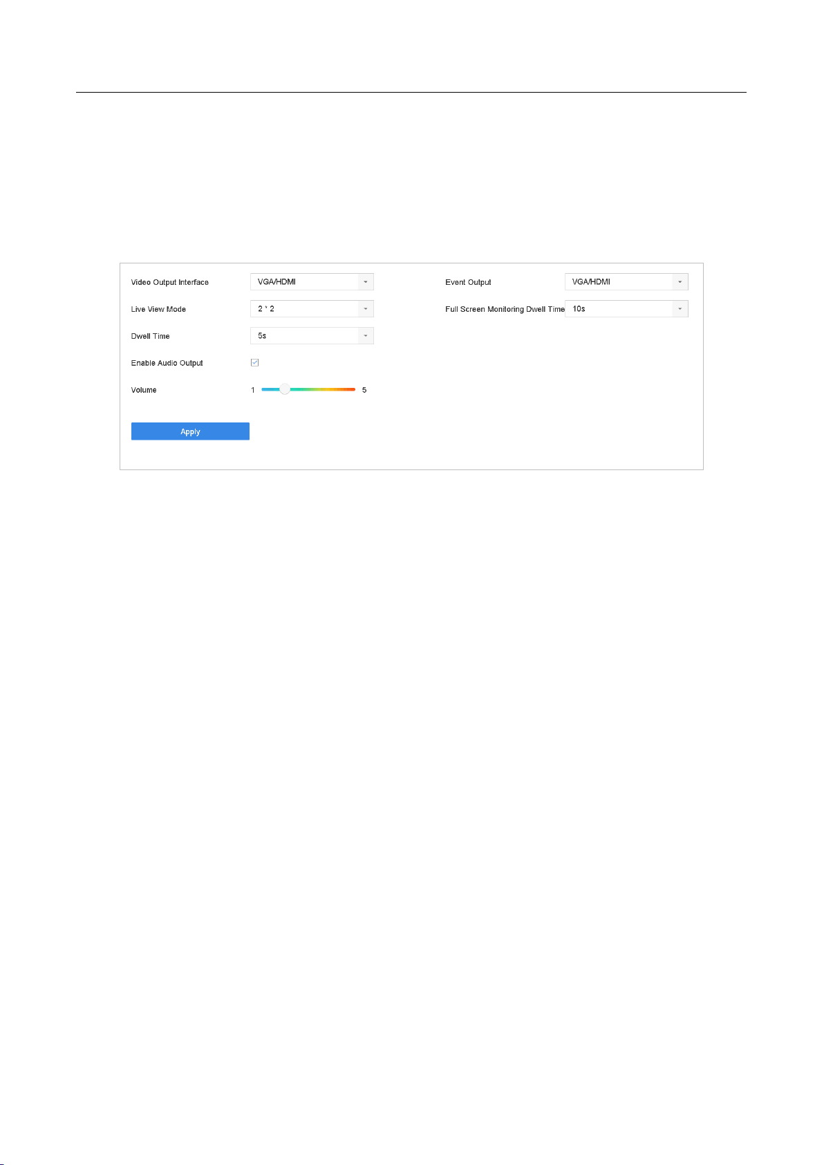
Network Video Recorder User Manual
49
5.2 Configure Live View Settings
Live View settings can be customized according to different needs. You can configure the output
interface, dwell time for screen to be shown, mute or turning on the audio, the screen number for
each channel, etc.
Step 1 Go to System > Live View > General.
Figure 5-3 Live View-General
Step 2 Configure the live view parameters.
Video Output Interface: Select the video output to configure.
Live View Mode: Select the display mode for live view, e.g., 2*2, 1*5, etc.
Dwell Time: The time in seconds to dwell between switching of cameras when enabling
auto-switch in Live View.
Enable Audio Output: Enable/disable audio output for the selected video output.
Volume: Adjust the volume of live view, playback and two-way audio for the selected output
interface.
Event Output: Select the output to show event video.
Full Screen Monitoring Dwell Time: Set the time in seconds to show alarm event screen.
Step 3 Click OK to save the settings.
5.3 Configure Live View Layout
Step 1 Go to System> Live View>View Settings.
Page 51

Network Video Recorder User Manual
50
Figure 5-4 Live View
Step 2 Select the video output interface, e.g., HDMI/ VGA or channel-zero.
Step 3 Select a window division mode from the toolbar.
Step 4 Select a division window, and double-click on the camera from the list to set the camera to the
window.
You can enter the number in the text field to quickly search the camera from the list.
You can also click-and-drag the camera to the desired window on the live view interface to set the
camera order.
Related Operation:
Click button to start live view for all the channels.
Click to stop all the live view.
Step 5 Click Apply to save the settings.
Page 52
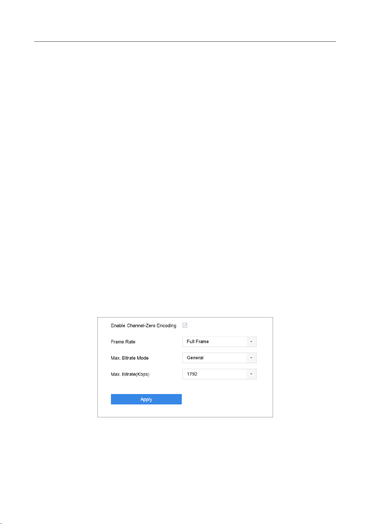
Network Video Recorder User Manual
51
5.4 Configure Auto-Switch of Cameras
You can set the auto-switch of cameras to play in different display modes.
Step 1 Go to System > Live View > General.
Step 2 Set the video output interface, live view mode and dwell time.
Video Output Interface: Select the video output interface.
Live View Mode: Select the display mode for live view, e.g., 2*2, 1*5, etc.
Dwell Time: The time in seconds to dwell between switching of cameras when enabling
auto-switch. The range is from 5s to 300s.
Step 3 Go to View Settings to set the view layout.
Step 4 Click OK to save the settings.
5.5 Configure Channel-Zero Encoding
Purpose:
You can enable the channel-zero encoding when you need to get a remote view of many channels
in real time from web browser or CMS (Client Management System) software, in order to decrease
the bandwidth requirement without affecting the image quality.
Step 1 Go to System > Live View > General.
Step 2 Select the video output interface to Channel-Zero.
Step 3 Go to System > Live View > Channel-Zero.
Step 4 Check the checkbox to enable the channel-zero.
Figure 5-5 Live View- Channel-Zero Encoding
Step 5 Configure the Frame Rate, Max. Bitrate Mode and Max. Bitrate. The higher frame rate and
bitrate settings result in the higher requirement of bandwidth.
Step 6 Click Apply.
Page 53

Network Video Recorder User Manual
52
Result:
You can view all of the channels in one screen using the CMS or web browser.
5.6 Use an Auxiliary Monitor
Certain features of the Live View are also available while in an Aux monitor. These features include:
Single Screen: Switch to a full screen display of the selected camera. Camera can be selected
from a dropdown list.
Multi-screen: Switch between different display layout options. Layout options can be selected
from a dropdown list.
Next Screen: When displaying less than the maximum number of cameras in Live View,
clicking this feature will switch to the next set of displays.
Playback: Enter into Playback mode.
PTZ Control: Enter PTZ Control mode.
Main Monitor: Enter Main operation mode.
In the live view mode of the main output monitor, the menu operation is not available while Aux
output mode is enabled.
Page 54

Network Video Recorder User Manual
53
Chapter 6 PTZ Control
6.1 PTZ Control Wizard
Before you start
Please make sure the connected IP camera supports the PTZ function and is properly connected.
Purpose
Follow the PTZ control wizard to guide you through the basic PTZ operation.
Step 1 Click on the quick settings toolbar of the PTZ camera live view. The PTZ control wizard
pops up as below.
Figure 6-1 PTZ Control Wizard
Step 2 Follow the wizard to adjust the PTZ view, focus, and zoom in/out the camera.
Step 3 (Optional) Check Do not show this prompt again.
Step 4 Click OK to exit.
6.2 Configure PTZ Parameters
Purpose
Follow the procedure to set the parameters for PTZ. The configuration of the PTZ parameters
should be done before you control the PTZ camera.
Page 55

Network Video Recorder User Manual
54
Step 1 Click on the quick settings toolbar of the PTZ camera live view. The PTZ control panel
displays on the right of the interface.
Step 2 Click PTZ Parameters Settings to set the PTZ parameters.
Figure 6-2 PTZ Parameters Settings
Step 3 Edit the parameters of the PTZ camera.
All the parameters should be exactly the same as the PTZ camera parameters.
Step 4 Click OK to save the settings.
6.3 Set PTZ Presets, Patrols & Patterns
Before you start:
Please make sure that the presets, patrols and patterns should be supported by PTZ protocols.
6.3.1 Set a Preset
Purpose:
Follow the steps to set the preset location which you want the PTZ camera to point to when an
event takes place.
Step 1 Click on the quick settings toolbar of the PTZ camera live view.
Page 56
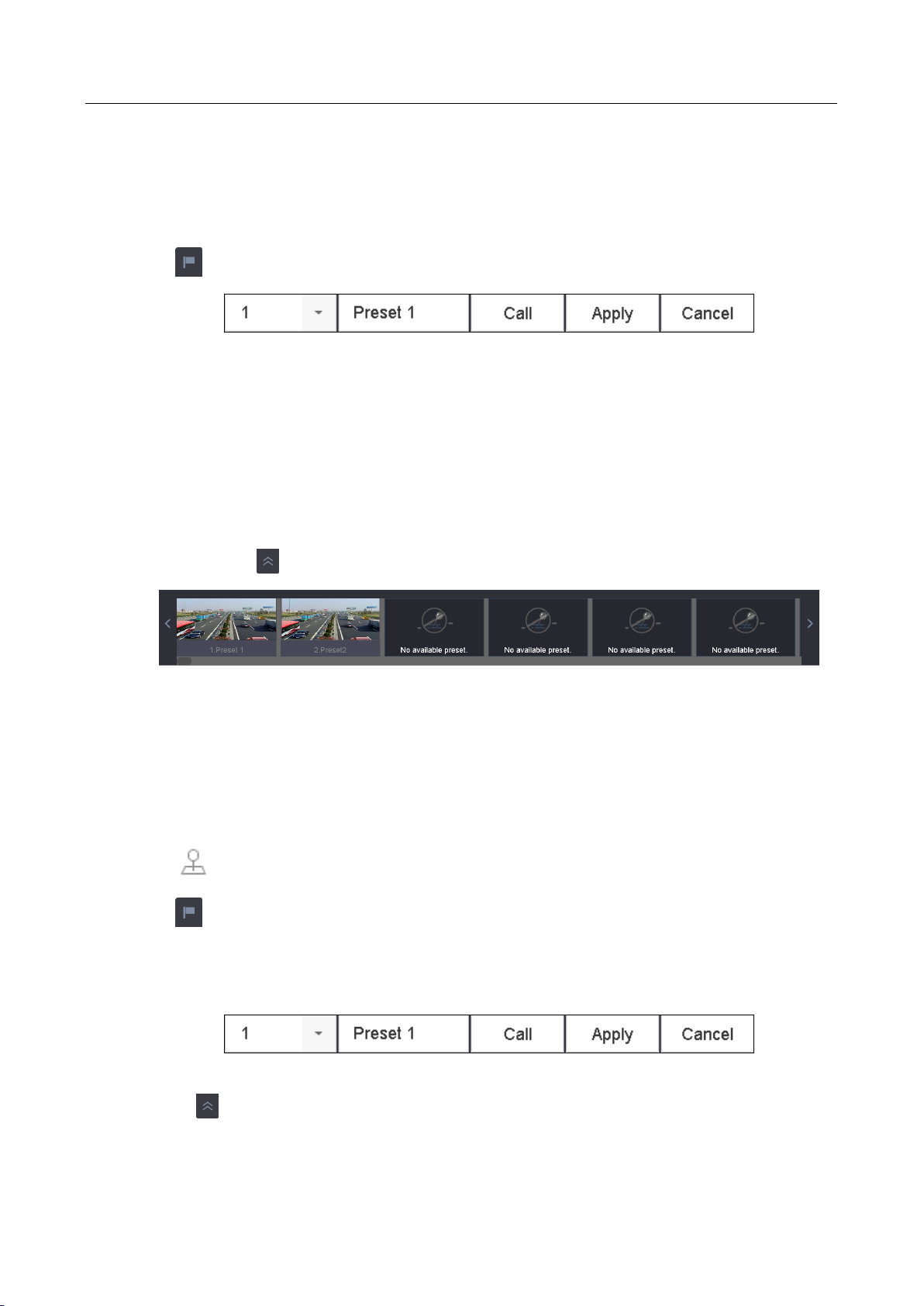
Network Video Recorder User Manual
55
The PTZ control panel displays on the right of the interface.
Step 2 Use the directional buttons on the PTZ control panel to wheel the camera to the location
where you want to set preset, and the zoom and focus operations can be recorded in the
preset as well.
Step 3 Click in the lower right corner of live view to set the preset.
Figure 6-3 Set Preset
Step 4 Select the preset No. (1~255) from the drop-down list.
Step 5 Enter the preset name in the text field.
Step 6 Click Apply to save the preset.
Step 7 Repeat steps 2-6 to save more presets.
Step 8 (Optional) Click Cancel to cancel the location information of the preset.
Step 9 (Optional) Click in the lower right corner of live view to view the configured presets.
Figure 6-4 View the Configured Presets
6.3.2 Call a Preset
Purpose:
This feature enables the camera to point to a specified position such as a window when an event
takes place.
Step 1 Click on the quick settings toolbar of the PTZ camera live view.
Step 2 Click in the lower right corner of live view.
Step 3 Select the preset No. from the drop-down list.
Step 4 Click Call to call it.
Figure 6-5 Call Preset (1)
Or click in the lower right corner of live view, and click the configured preset to call it.
Page 57

Network Video Recorder User Manual
56
Figure 6-6 Call Preset (2)
6.3.3 Set a Patrol
Purpose:
Patrols can be set to move the PTZ to different key points and have it stay there for a set duration
before moving on to the next key point. The key points are corresponding to the presets.
Step 1 Click on the quick settings toolbar of the PTZ camera live view.
The PTZ control panel displays on the right of the interface.
Step 2 Click Patrol to configure patrol.
Figure 6-7 Patrol Configuration
Step 3 Select the patrol No. in the text field.
Step 4 Click Set to enter the Patrol Settings interface.
Figure 6-8 Patrol Settings
Step 5 Click to add key point for the patrol.
Page 58

Network Video Recorder User Manual
57
Figure 6-9 Key Point Configuration
1) Configure key point parameters.
Preset: It determines the order at which the PTZ will follow while cycling through the patrol.
Speed: It defines the speed at which the PTZ will move from one key point to the next.
Duration: It refers to the time span to stay at the corresponding key point.
2) Click Apply to save the key points to the patrol.
Step 6 (Optional) Click to edit the added key point.
Figure 6-10 Edit Key Point
Step 7 (Optional) Select a key point and click to delete it.
Step 8 (Optional) Click or to adjust the key point order.
Step 9 Click Apply to save the settings of the patrol.
Step 10 Repeat steps 3-9 to set more patrols.
6.3.4 Call a Patrol
Purpose:
Calling a patrol makes the PTZ to move according to the predefined patrol path.
Step 1 Click on the quick settings toolbar of the PTZ camera live view.
Page 59

Network Video Recorder User Manual
58
The PTZ control panel displays on the right of the interface.
Step 2 Click Patrol on the PTZ control panel.
Figure 6-11 Patrol Configuration
Step 3 Select a patrol in the text field.
Step 4 Click Call to call it.
Step 5 (Optional) Click Stop to stop calling it.
6.3.5 Set a Pattern
Purpose:
Patterns can be set by recording the movement of the PTZ. You can call the pattern to make the
PTZ movement according to the predefined path.
Step 1 Click on the quick settings toolbar of the PTZ camera live view.
The PTZ control panel displays on the right of the interface.
Step 2 Click Pattern to configure pattern.
Figure 6-12 Pattern Configuration
Step 3 Select the pattern No. in the text field.
Step 4 Set the pattern.
1) Click Record to start recording.
2) Click corresponding buttons on the control panel to move the PTZ camera.
3) Click Stop to stop recording.
The movement of the PTZ is recorded as the pattern.
Step 5 Repeat steps 3-4 to set more patterns.
Page 60
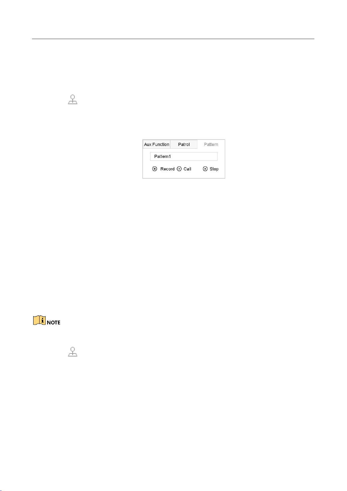
Network Video Recorder User Manual
59
6.3.6 Call a Pattern
Purpose:
Follow the procedure to move the PTZ camera according to the predefined patterns.
Step 1 Click on the quick settings toolbar of the PTZ camera live view.
The PTZ control panel displays on the right of the interface.
Step 2 Click Pattern to configure pattern.
Figure 6-13 Pattern Configuration
Step 3 Select a pattern in the text field.
Step 4 Click Call to call it.
Step 5 (Optional) Click Stop to stop calling it.
6.3.7 Set Linear Scan Limits
Before you start:
Please make sure the connected IP camera supports the PTZ function, and is properly connected.
Purpose:
The linear scan can be enabled to trigger the scan in the horizontal direction in the predefined
range.
This function is supported by some certain models.
Step 1 Click on the quick settings toolbar of the PTZ camera live view.
The PTZ control panel displays on the right of the interface.
Step 2 Click the directional buttons to wheel the camera to the location where you want to set the
limit, and click Left Limit or Right Limit to link the location to the corresponding limit.
Page 61

Network Video Recorder User Manual
60
The speed dome starts linear scan from the left limit to the right limit, and you must set the left
limit on the left side of the right limit, as well the angle from the left limit to the right limit should
be no more than 180º.
6.3.8 Call Linear Scan
Before operating this function, make sure the connected camera supports the linear scan and is in
HIKVISION protocol.
Purpose:
Follow the procedure to call the linear scan in the predefined scan range.
Step 1 Click on the quick settings toolbar of the PTZ camera live view.
The PTZ control panel displays on the right of the interface.
Step 2 Click Linear Scan to start the linear scan and click it again to stop it.
Step 3 (Optional) Click Restore to clear the defined left limit and right limit data.
Reboot the camera to take the settings into effect.
6.3.9 One-touch Park
Before operating this function, make sure the connected camera supports the linear scan and is in
HIKVISION protocol.
Purpose
For some certain model of the speed dome, it can be configured to start a predefined park action
(scan, preset, patrol and etc.) automatically after a period of inactivity (park time).
Step 1 Click on the quick settings toolbar of the PTZ camera live view.
The PTZ control panel displays on the right of the interface.
Step 2 Click Park (Quick Patrol), Park (Patrol 1) or Park (Preset 1) to activate the park action.
Park (Quick Patrol): The dome starts patrol from the predefined preset 1 to preset 32 in
order after the park time. The undefined preset will be skipped.
Page 62

Network Video Recorder User Manual
61
Park (Patrol 1): The dome starts moving according to the predefined patrol 1 path after the
park time.
Park (Preset 1): The dome moves to the predefined preset 1 location after the park time.
The park time can only be set via the speed dome configuration interface. The value is 5s by
default.
Step 3 Click Stop Park (Quick Patrol), Stop Park (Patrol 1) or Stop Park (Preset 1) to inactivate it.
6.4 Auxiliary Functions
Before you start
Please make sure the connected IP camera supports the PTZ function, and is properly connected.
Purpose
You can operate the auxiliary functions including light, wiper, 3D positioning, and center on the PTZ
control panel.
Step 1 Click on the quick settings toolbar of the PTZ camera live view.
The PTZ control panel displays on the right of the interface.
Step 2 Click Aux Function.
Figure 6-14 Aux Function Configuration
Step 3 Click the icons to operate the aux functions. See the table for the description of the icons.
Page 63

Network Video Recorder User Manual
62
Table 6-1 Description of Aux Functions Icons
Icon
Description
Light on/off
Wiper on/off
3D positioning
Center
Page 64

Network Video Recorder User Manual
63
Chapter 7 Storage
7.1 Storage Device Management
7.1.1 Install the HDD
Before startup of the device, install and connect the HDD to the device. Refer to the Quick Start
Guide for the installation instructions.
7.1.2 Add the Network Disk
You can add the allocated NAS or disk of IP SAN to device, and use it as network HDD. Up to 8
network disks can be added.
Adding NAS
Step 1 Go to Storage > Storage Device.
Step 2 Click Add to enter the Custom Add interface.
Step 3 Select the NetHDD from the drop-down list.
Step 4 Select the type to NAS.
Step 5 Enter the NetHDD IP address in the text field.
Step 6 Click Search to search the available NAS disks.
Page 65

Network Video Recorder User Manual
64
Figure 7-1 Add NAS Disk
Step 7 Select the NAS disk from the list shown below, or you can manually enter the directory in the
text field of NetHDD Directory.
Step 8 Click the OK to complete the adding of the NAS disk.
Result:
After having successfully added the NAS disk, return to the HDD Information menu. The added
NetHDD will be displayed in the list.
Adding IP SAN
Step 1 Go to Storage > Storage Device.
Step 2 Click Add to enter the Custom Add interface.
Step 3 Select the NetHDD from the drop-down list.
Step 4 Select the type to IP SAN.
Step 5 Enter the NetHDD IP address in the text field.
Step 6 Click Search to search the available IP SAN disks.
Step 7 Select the IP SAN disk from the list shown below.
Step 8 Click OK to complete the adding of the IP SAN disk.
Page 66
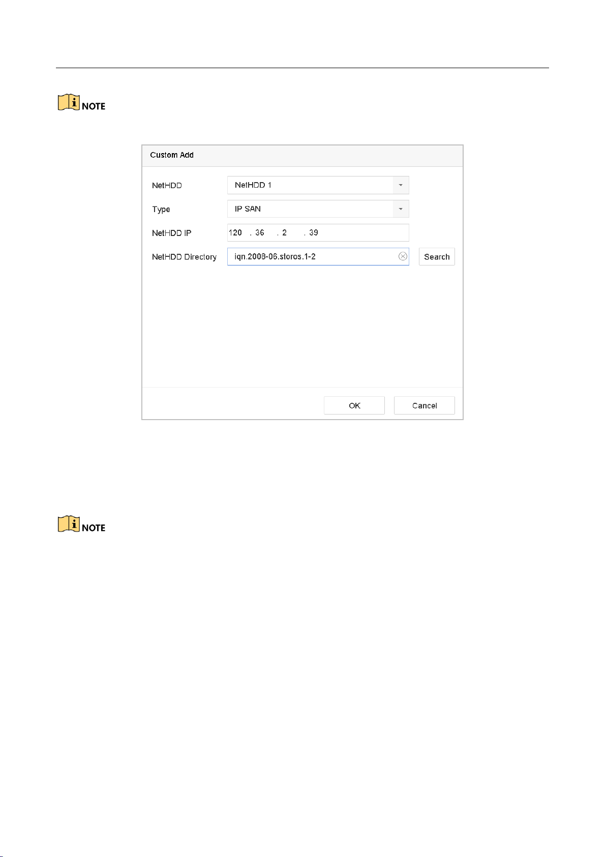
Network Video Recorder User Manual
65
Up to 1 IP SAN disk can be added.
Figure 7-2 Add IP SAN Disk
Result:
After having successfully added the IP SAN disk, return to the HDD Information menu. The added
NetHDD will be displayed in the list.
If the installed HDD or NetHDD is uninitialized, please select it and click the Init button for
initialization.
7.1.3 Configure eSATA for Data Storage
When there is an external eSATA device connected to device, you can configure eSATA for the data
storage, and you can manage the eSATA in the device.
Step 1 Click Storage > Advanced.
Step 2 Select the eSATA type to Export or Record/Capture from the dropdown list of eSATA.
Export: use the eSATA for backup.
Record/Capture: use the eSATA for record/capture. Refer to the following steps for operating
instructions.
Page 67

Network Video Recorder User Manual
66
Figure 7-3 Set eSATA Mode
Step 3 When the eSATA type is selected to Record/Capture, enter the storage device interface.
Step 4 Edit the property of the selected eSATA, or initialize it is required.
7.2 Storage Mode
7.2.1 Configure HDD Group
Purpose:
Multiple HDDs can be managed in groups. Video from specified channels can be recorded onto a
particular HDD group through HDD settings.
Step 1 Go to Storage> Storage Device.
Step 2 Check the checkbox to select the HDD to set the group.
Figure 7-4 Storage Device
Step 3 Click to enter the Local HDD Settings interface.
Page 68
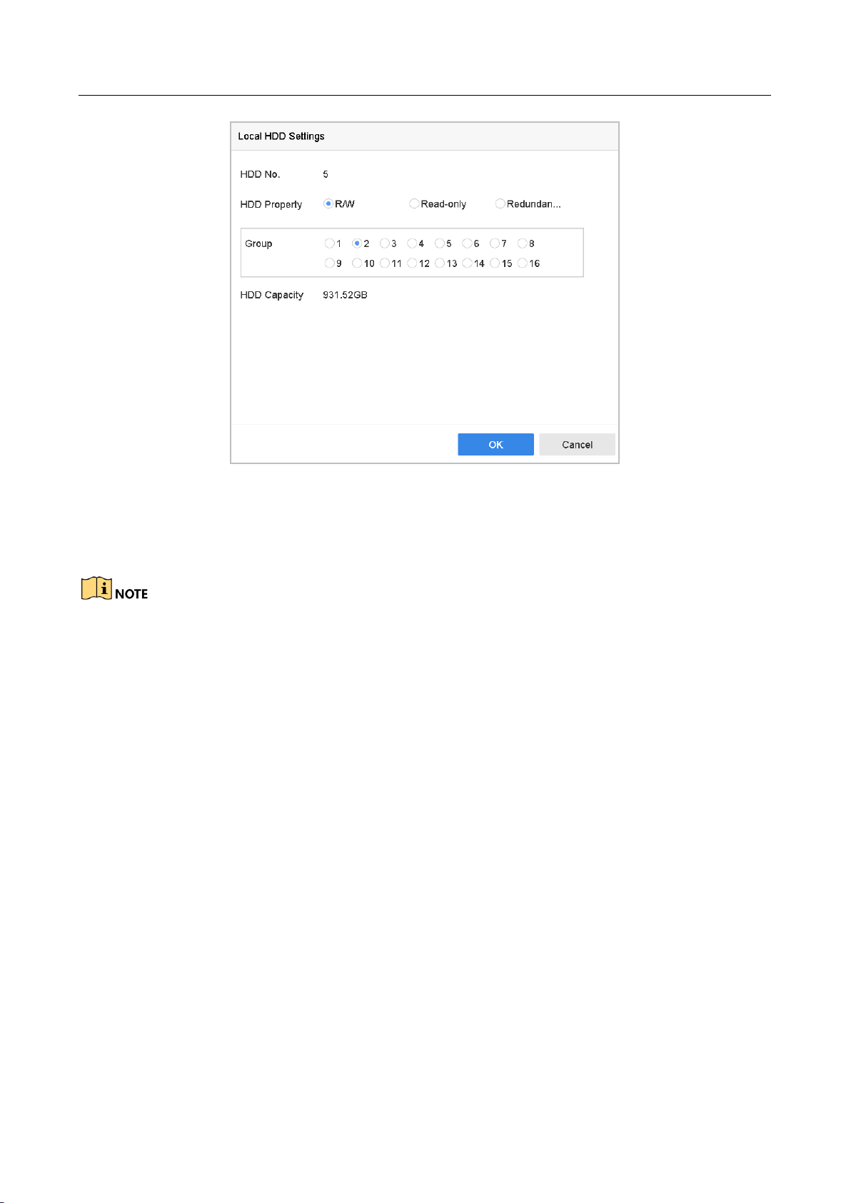
Network Video Recorder User Manual
67
Figure 7-5 Local HDD Settings
Step 4 Select the Group number for the current HDD.
Step 5 Click OK.
Regroup the cameras for HDD if the HDD group number is changed.
Step 6 Go to Storage> Storage Mode.
Step 7 Check the checkbox of Group tab.
Step 8 Select the group No. from the list.
Step 9 Check the checkbox to select the IP camera (s) to record/capture on the HDD group.
Page 69

Network Video Recorder User Manual
68
Figure 7-6 Storage Mode-HDD Group
Step 10 Click Apply.
Reboot the device to activate the new storage mode settings.
7.2.2 Configure HDD Quota
Purpose:
Each camera can be configured with allocated quota for the storage of recorded files or captured
pictures.
Step 1 Go to Storage > Storage Mode.
Step 2 Check the checkbox of Quota tab.
Step 3 Select a camera to set quota.
Step 4 Enter the storage capacity in the text fields of Max. Record Capacity (GB) and Max. Picture
Capacity (GB).
Page 70
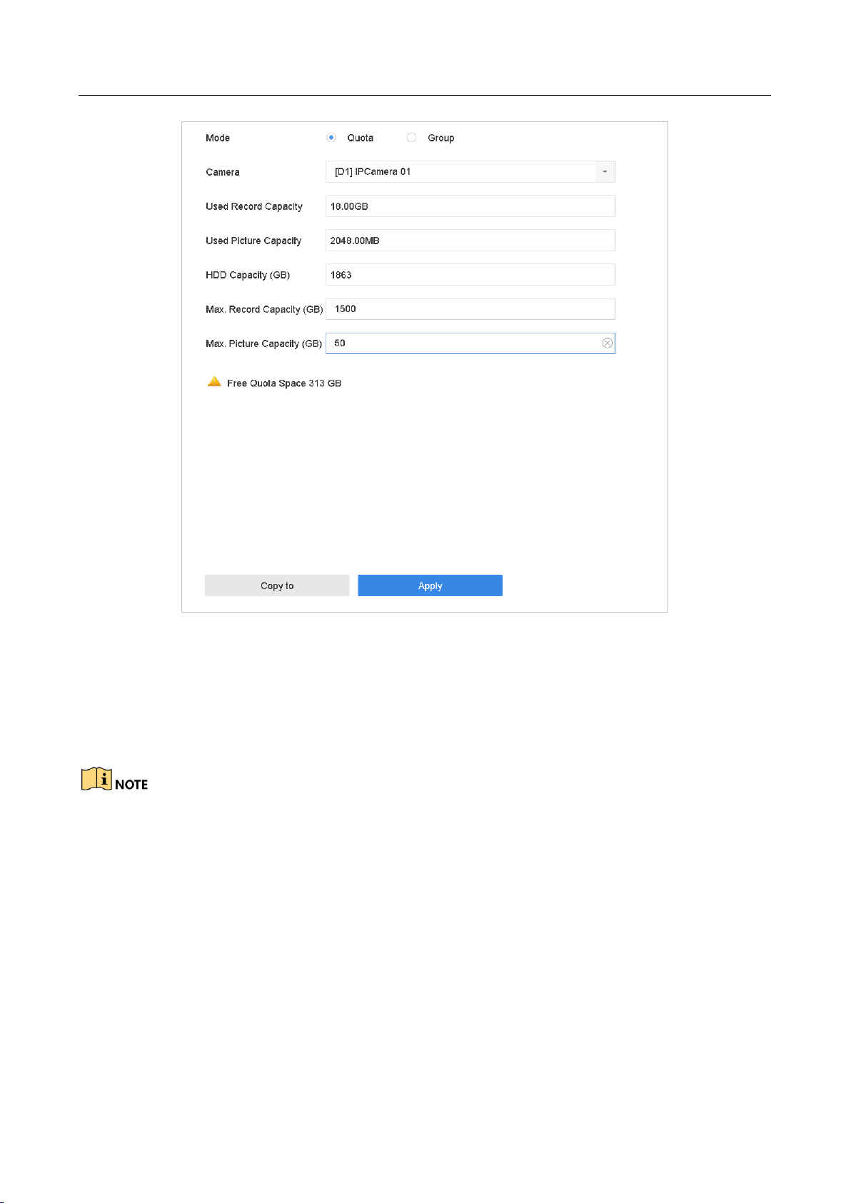
Network Video Recorder User Manual
69
Figure 7-7 Storage Mode-HDD Quota
Step 5 (Optional) You can click Copy to if you want to copy the quota settings of the current camera to
other cameras.
Step 6 Click the Apply button to apply the settings. Reboot the device to activate the new storage
mode settings.
When the quota capacity is set to 0, all cameras will use the total capacity of HDD for record and
picture capture.
7.3 Recording Parameters
7.3.1 Main Stream
The Main Stream refers to the primary stream that affects data recorded to the hard disk drive and
will directly determine your recording quality and image size.
Comparing with the sub-stream, the main stream can provide a higher quality video with higher
resolution and frame rate.
Page 71

Network Video Recorder User Manual
70
Frame Rate (FPS - Frames Per Second): refers to how many frames are captured each second.
A higher frame rate is advantageous when there is movement in the video stream, as it
maintains image quality throughout.
Resolution: Image resolution is a measure of how much detail a digital image can hold: the
greater the resolution, the greater the level of detail. Resolution can be specified as the
number of pixel-columns (width) by the number of pixel-rows (height), e.g.,1024×768.
Bitrate: The bit rate (in kbit/s or Mbit/s) is often referred to as speed, but actually defines the
number of bits/time unit and not distance/time unit.
Enable H.264+ Mode: The H.264+ mode helps to ensure the high video quality with a lowered
bitrate. It can effectively reduces the need of bandwith and HDD storage space.
A higher resolution, frame rate and bitrate setting will provide you the better video quality, but it
will also require more internet bandwidth and use more storage space on the hard disk drive.
7.3.2 Sub-Stream
The sub-stream is a second codec that runs alongside the mainstream. It allows you to reduce the
outgoing internet bandwidth without sacrificing your direct recording quality.
The sub-stream is often exclusively used by smartphone applications to view live video. Users with
limited internet speeds may benefit most from this setting.
7.3.3 Picture
The picture refers to the live picture capture in continuous or event recording type.
Picture Quality: set the picture quality to low, medium or high. The higher picture quality results
in more storage space requirement.
Interval: the interval of capturing live picture.
7.3.4 ANR
ANR (Automatic Network Replenishment) function which enables the IP camera to save the
recording files in the local storage when the network is disconnected, and when the network is
resumed, it uploads the files to the device.
Enable the ANR (Automatic Network Replenishment) function via the web browser
(Configuration > Storage > Schedule Settings > Advanced).
7.3.5 Configure Advanced Recording Settings
Step 1 Go to Storage > Schedule Settings > Record Schedule/Capture Schedule.
Step 2 Check the checkbox of Enable to enable scheduled recording.
Step 3 Click Advanced to set the recording parameters.
Page 72
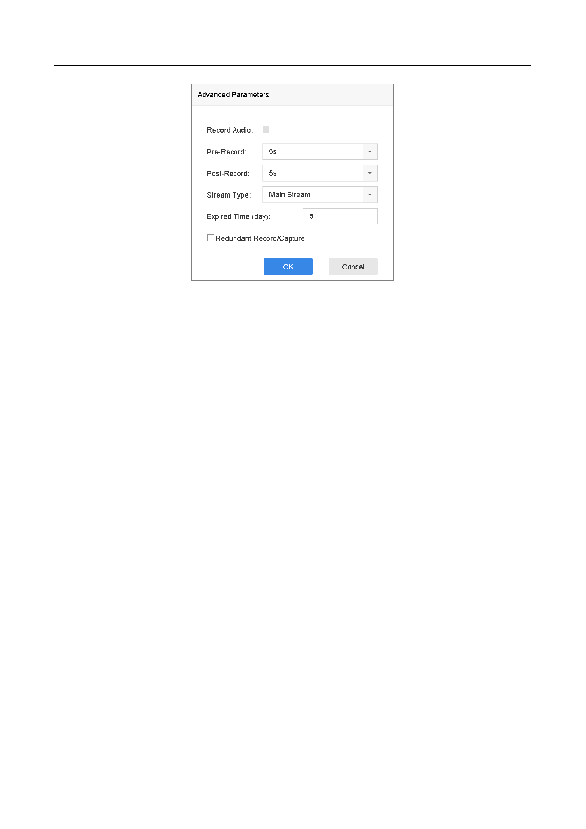
Network Video Recorder User Manual
71
Figure 7-8 Advanced Record Settings
Record Audio: Check the checkbox to enable or disable audio recording.
Pre-record: The time you set to record before the scheduled time or event. For example, when
an alarm triggers the recording at 10:00, and if you set the pre-record time as 5 seconds, the
camera records at 9:59:55.
Post-record: The time you set to record after the event or the scheduled time. For example,
when an alarm triggered recording ends at 11:00, and if you set the post-record time as 5
seconds, it records till 11:00:05.
Expired Time: The expired time is period for a recorded file to be kept in the HDD. When the
deadline is reached, the file will be deleted. If you set the expired time to 0, the file will not be
deleted. The actual keeping time for the file should be determined by the capacity of the HDD.
Redundant Record/Capture: By enabling redundant record or capture you save the record and
captured picture in the redundant HDD. See Chapter Configure Redundant Recording and
Capture.
Stream Type: Main stream and sub-stream are selectable for recording. When you select
sub-stream, you can record for a longer time with the same storage space.
Step 4 Click OK to save the settings.
7.4 Configure Recording Schedule
Set the record schedule, and then the camera automatically starts/stops recording according to the
configured schedule.
Before you start
Make sure you have installed the HDDs to the device or added the network disks before you want
to store the video files, pictures and log files.
Refer to the Quick Start Guide for the HDD installation.
Page 73

Network Video Recorder User Manual
72
Refer to Chapter 7.1.2 Add the Network Disk for network HDD connections.
Step 1 Go to Storage > Recording Schedule.
Step 2 Select a camera.
Step 3 Check Enable Schedule.
Step 4 Select a Record Type. The record type can be Continuous, Motion Detection, Alarm, Motion |
Alarm, Motion & Alarm, and Event.
Different recording types are configurable.
Continuous: scheduled recording.
Event: recording triggered by all event triggered alarm.
Motion: recording triggered by motion detection.
Alarm: recording triggered by alarm.
M/A: recording triggered by either motion detection or alarm.
M&A: recording triggered by motion detection and alarm.
POS Event: recording triggered by POS and alarm.
Step 5 Select a day and click-and-drag the mouse on the time bar to set the record schedule.
Figure 7-9 Record Schedule
Step 6 Repeat the above steps to schedule recording or capture for other days in the week.
Page 74

Network Video Recorder User Manual
73
Step 7 Click Apply to save the settings.
To enable Motion, Alarm, M | A (motion or alarm), M & A (motion and alarm) and Event triggered
recording and capture, you must configure the motion detection settings, alarm input settings and
other events as well. Please refer to Chapter 11 Event and Alarm Settings and Chapter 12 VCA
Event Alarm for details.
7.5 Configure Continuous Recording
Step 1 Go to Camera > Encoding Parameters > Recording Parameters.
Step 2 Set the continuous main stream/sub-stream recording parameters for the camera.
Step 3 Go to Storage > Recording Schedule.
Step 4 Select Continuous recording type.
Step 5 Set the schedule for the continuous recording. Refer to Chapter 7.4 Configure Recording
Schedule for details.
7.6 Configure Motion Detection Triggered Recording
You can configure the recording triggered by the motion detection event.
Step 1 Go to System > Event > Normal Event > Motion Detection.
Step 2 Configure the motion detection and select the channel (s) to trigger the recording when motion
event occurs. Refer to Chapter 11.3 Configure Motion Detection Alarm for details.
Step 3 Go to Camera > Encoding Parameters > Recording Parameters.
Step 4 Set the event main stream/sub-stream recording parameters for the camera.
Step 5 Go to Storage > Recording Schedule.
Step 6 Select Motion recording type.
Step 7 Set the schedule for the motion detection triggered recording. Refer to Chapter 7.4 Configure
Recording Schedule for details.
7.7 Configure Event Triggered Recording
You can configure the recording triggered by the motion detection, vehicle detection, line crossing
detection, etc.
Step 1 Go to System > Event.
Page 75

Network Video Recorder User Manual
74
Step 2 Configure the event detection and select the channel (s) to trigger the recording when event
occurs. Refer to Chapter 11 Event and Alarm Settings and Chapter 12 VCA Event Alarm for
details.
Step 3 Go to Camera > Encoding Parameters > Recording Parameters.
Step 4 Set the event main stream/sub-stream recording parameters for the camera.
Step 5 Go to Storage > Recording Schedule.
Step 6 Select Event recording type.
Step 7 Set the schedule for the event triggered recording. Refer to Chapter 7.4 Configure Recording
Schedule for details.
7.8 Configure Alarm Triggered Recording
You can configure the recording triggered by the motion detection, vehicle detection, line crossing
detection, etc.
Step 1 Go to System > Event > Normal Event > Alarm Input.
Step 2 Configure the alarm input and select the channel (s) to trigger the recording when alarm occurs.
Refer to Chapter 11 Event and Alarm Settings and Chapter 12 VCA Event Alarm for details.
Step 3 Go to Camera > Encoding Parameters > Recording Parameters.
Step 4 Set the event main stream/sub-stream recording parameters for the camera.
Step 5 Go to Storage > Recording Schedule.
Step 6 Select Alarm recording type.
Step 7 Set the schedule for the alarm triggered recording. Refer to Chapter 7.4 Configure Recording
Schedule for details.
7.9 Configure POS Event Triggered Recording
You can configure the recording triggered by the connected POS event, such as the transaction, etc.
Step 1 Go to System >POS Settings.
Step 2 Configure the POS and select the channel (s) in the Event Linkage to trigger the recording when
POS event occurs. Refer to Chapter 13 for details.
Step 3 Go to Camera > Encoding Parameters > Recording Parameters.
Step 4 Set the event main stream/sub-stream recording parameters for the camera.
Step 5 Go to Storage > Recording Schedule.
Step 6 Select POS Event recording type.
Page 76
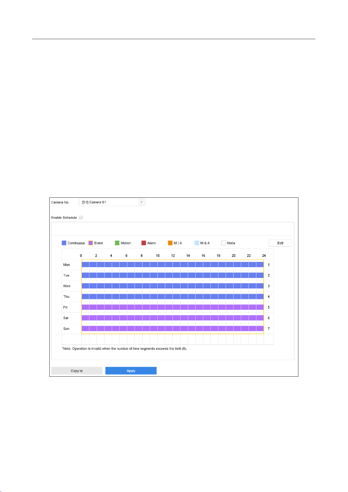
Network Video Recorder User Manual
75
Step 7 Set the schedule for the POS event triggered recording. Refer to Chapter 7.4 Configure
Recording Schedule for details.
7.10 Configure Picture Capture
The picture refers to the live picture capture in continuous or event recording type.
Step 1 Go to Camera > Encoding Parameters > Capture.
Step 2 Set the picture parameters.
Resolution: set the resolution of the picture to capture.
Picture Quality: set the picture quality to low, medium or high.
Interval: the interval of capturing live picture.
Step 3 Go to Storage > Capture Schedule.
Step 4 Select the camera to configure the picture capture.
Figure 7-10 Set Picture Capture Schedule
Step 5 Set the picture capture schedule. Refer to Chapter 7.4 Configure Recording Schedule for details.
7.11 Configure Holiday Recording and Capture
Purpose:
Page 77

Network Video Recorder User Manual
76
Follow the steps to configure the record or capture schedule on holiday for that year. You may
want to have different plan for recording and capture on holiday.
Step 1 Go to System > Holiday Settings.
Step 2 Select a holiday item from the list and click .
Step 3 Check the Enable to configure the holiday.
Figure 7-11 Edit Holiday Settings
1) Edit the holiday name.
2) Select the mode to by date, by week or by month.
3) Set the start and end date of the holiday.
4) Click OK.
Step 4 Set the schedule for the holiday recording. Refer to Chapter 7.4 Configure Recording Schedule
for details.
7.12 Configure Redundant Recording and Capture
Purpose:
Enabling redundant recording and capture, which means saving the record files and captured
pictures not only in the R/W HDD but also in the redundant HDD, will effectively enhance the data
safety and reliability. .
You must set the storage mode to Group before you set the HDD property to Redundancy. For
detailed information, please refer to Chapter 7.2.1 Configure HDD Group. There should be at least
another HDD which is in Read/Write status.
Step 1 Go to Storage > Storage Device.
Page 78

Network Video Recorder User Manual
77
Step 2 Select an HDD from the list and Click to enter the Local HDD Settings interface.
Step 3 Set the HDD property to Redundancy.
Figure 7-12 HDD Property-Redundancy
Step 4 Go to Storage > Schedule Settings > Record Schedule/Capture Schedule.
Step 5 Click Advanced to set the camera recording parameters.
Figure 7-13 Record Parameters
Step 6 Check the checkbox of Redundant Record/Capture.
Step 7 Click OK to save settings.
Page 79

Network Video Recorder User Manual
78
Chapter 8 Disk Array
Purpose
Disk array is a data storage virtualization technology that combines multiple physical disk drive
components into a single logical unit. An array stores data over multiple HDDs to provide enough
redundancy so that data can be recovered if one disk fails. Data is distributed across the drives in
one of several ways called "RAID levels", depending on what level of redundancy and performance
is required.
8.1 Create Disk Array
Purpose
The device supports the disk array that is realized by software. You can enable the RAID function as
required. Two ways are available for creating array: one-touch configuration and manual
configuration. The following flow chart shows the process of creating array.
8.1.1 Enable RAID
Purpose
Perform the following steps to enable the disk array function.
Step 1 Go to Storage > Advanced.
Figure 8-1 Advanced
Step 2 Check Enable RAID.
Step 3 Click Apply.
Step 4 Reboot device to take effect the settings.
Page 80

Network Video Recorder User Manual
79
8.1.2 One-Touch Creation
Purpose
One-touch configuration helps you to quickly create the disk array. By default, the array type
created by one-touch configuration is RAID 5.
Before you start
Enable RAID function. For details, refer to Chapter 8.1.1 Enable RAID.
Install at least 3 HDDs. If more than 10 HDDs are installed, 2 arrays will be created. To maintain
reliable and stable running of the HDDs, it is recommended to use enterprise-level HDDs with
the same model and capacity.
Step 1 Go to Storage > RAID Setup > Physical Disk.
Figure 8-2 Physical Disk
Step 2 Click One-touch Config.
Step 3 Edit the array name in Array Name text filed and click OK to start configuring.
If you install 4 HDDs or more, a hot spare disk for array rebuilding will be created.
Step 4 A message box will pop up when the array creation is completed, click OK on it.
Step 5 Optionally, the device will automatically initialize the created array. Go to Storage > RAID
Setup > Array view the information of created arrray.
8.1.3 Manual Creation
Purpose
Manually create the array of RAID 0, RAID 1, RAID 5, RAID 6, and RAID 10.
Step 1 Go to Storage > RAID Setup > Physical Disk.
Step 2 Click Create.
Page 81

Network Video Recorder User Manual
80
Table 8-1 Create Array
Step 3 Enter the array name.
Step 4 Select RAID Level as RAID 0, RAID 1, RAID 5, RAID 6, or RAID 10 as required.
Step 5 Select the physical disks to constitute array.
Table 8-2 Required Number of HDD
RAID Level
Required Number of HDD
RAID 0
At least 2 HDDs.
RAID 1
At least 2 HDDs.
RAID 5
At least 3 HDDs.
RAID 6
At least 4 HDDs.
RAID 10
The number of HDD must be an even ranges from 4 to 16.
Step 6 Click OK.
Step 7 Optionally, the device will automatically initialize the created array. Go to Storage > RAID
Setup > Array view the information of created arrray.
Figure 8-3 Array List
Page 82

Network Video Recorder User Manual
81
8.2 Rebuild Array
Purpose
The status of array includes Functional, Degraded and Offline. To ensure the high security and
reliability of the data stored in array, you should take immediate and proper maintenance at arrays
according their status.
Functional: No disk loss in the array.
Offline: The number of lost disks has exceeded the limit.
Degraded: If amount of HDD fail in array, array degrades. You should recover it to Functional by
array rebuilding.
8.2.1 Configure Hot Spare Disk
Purpose
Hot spare disks are required for disk array automatic rebuilding.
Step 1 Go to Storage > RAID Setup > Physical Disk.
Figure 8-4 Physical Disk
Step 2 Click of an available HDD to set it as the hot spare disk.
8.2.2 Automatically Rebuild Array
Purpose
The device can automatically rebuild degraded arrays with the hot spare disks.
Before you start
Create hot spare disks. For details, refer to Chapter 8.2.1 Configure Hot Spare Disk.
Step 1 The device will automatically rebuild the degraded arrays with the hot spare disks. Go to
Storage > RAID Setup > Array to view rebuilding progress.
Page 83
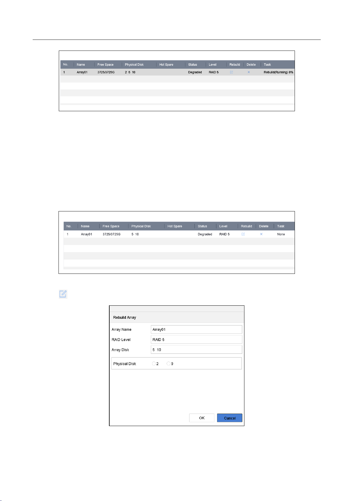
Network Video Recorder User Manual
82
Figure 8-5 Array List
8.2.3 Manually Rebuild Array
Purpose
If no hot spare disks are configured, rebuild the degraded array manually.
Before you start
At least one available physical disk should exist for rebuilding the array.
Step 1 Go to Storage > RAID Setup > Array.
Figure 8-6 Array List
Step 2 Click of degraded array.
Figure 8-7 Rebuild Array
Page 84
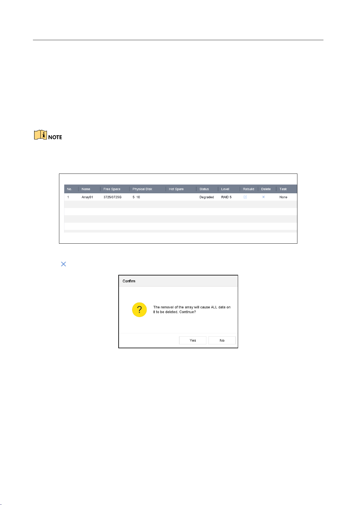
Network Video Recorder User Manual
83
Step 3 Select the available physical disk.
Step 4 Click OK.
Step 5 Click OK on the pop up message box “Do not unplug the physical disk when it is under
rebuilding”.
8.3 Delete Array
Deleting array will delete all the data saved in it.
Step 1 Go to Storage > RAID Setup > Array.
Figure 8-8 Array List
Step 2 Click of array to delete.
Figure 8-9 Attention
Step 3 Click Yes on the popup message box.
8.4 Check and Edit Firmware
Purpose
You can view the information of the firmware and set the background task speed on the Firmware
interface.
Step 1 Go to Storage > RAID Setup > Firmware.
Page 85

Network Video Recorder User Manual
84
Figure 8-10 Firmware
Step 2 Optionally, set the Background Task Speed.
Step 3 Click Apply.
Page 86
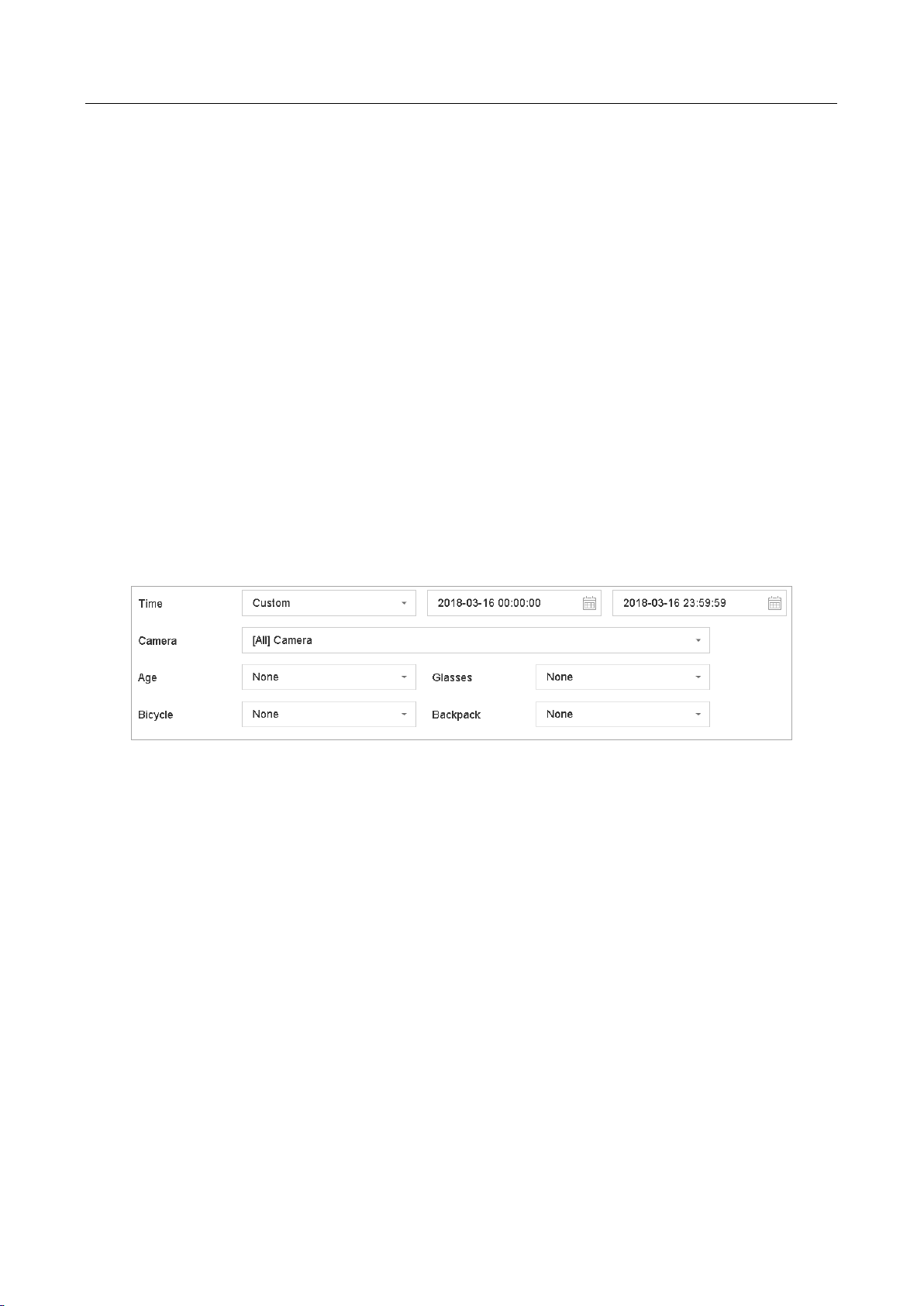
Network Video Recorder User Manual
85
Chapter 9 File Management
9.1 Search and Export Human Files
9.1.1 Search Human Files
Purpose
Specify detailed conditions to search human files.
Before you start
Configure human body detection function for the cameras you want to search and export human
files.
Step 1 Go to File Management > Human File.
Step 2 Click Show More and specify detailed conditions, including time, camera, people appearance,
etc.
Figure 9-1 Search Conditions
Step 3 Click Search to display results. The matched files are displayed in thumbnail or list.
Step 4 Select Target Picture or Source Picture in menu bar to display related pictures only. Select
Video or Picture to specify the file type.
Target Picture: Display the search results of people close-up.
Source Picture: Display the search results of original picture captured by camera.
Group: Sort the search results by selected item.
9.1.2 Export Human Files
Purpose
Export files for backup purposes using USB device (USB flash drive, USB HDD, USB optical disc
drive), SATA optical disc drive or eSATA HDD.
Step 1 Search for the human files to export. For details, see 9.1.1 Search Human Files.
Step 2 Click files and click Export.
Page 87

Network Video Recorder User Manual
86
Figure 9-2 Export Files
Step 3 Click OK to export pictures to backup device.
9.2 Search and Export Vehicle Files
9.2.1 Search Vehicle Files
Purpose
Specify detailed conditions to search vehicle files.
Before you start
Configure vehicle detection function for the cameras you want to search and export vehicle files.
Step 1 Go to File Management > Vehicle Files.
Step 2 Click Show More and specify detailed conditions, including time, camera, vehicle appearance,
etc.
Page 88

Network Video Recorder User Manual
87
Figure 9-3 Advanced Search
Step 3 Click Search to display results. The matched files are displayed in thumbnail or list.
Step 4 Select Target Picture or Source Picture in menu bar to display related pictures only. Select
Video or Picture to specify the file type.
Target Picture: Display the search results of vehicle close-up.
Source Picture: Display the search results of original picture captured by camera.
Group: Sort the search results by selected item.
9.2.2 Export Vehicle Files
Purpose
Export files for backup purposes using USB device (USB flash drive, USB HDD, USB optical disc
drive), SATA optical disc drive or eSATA HDD.
Step 1 Search for the vehicle files to export. For details, see 9.2.1 Search Vehicle Files.
Step 2 Click files and click Export.
Page 89
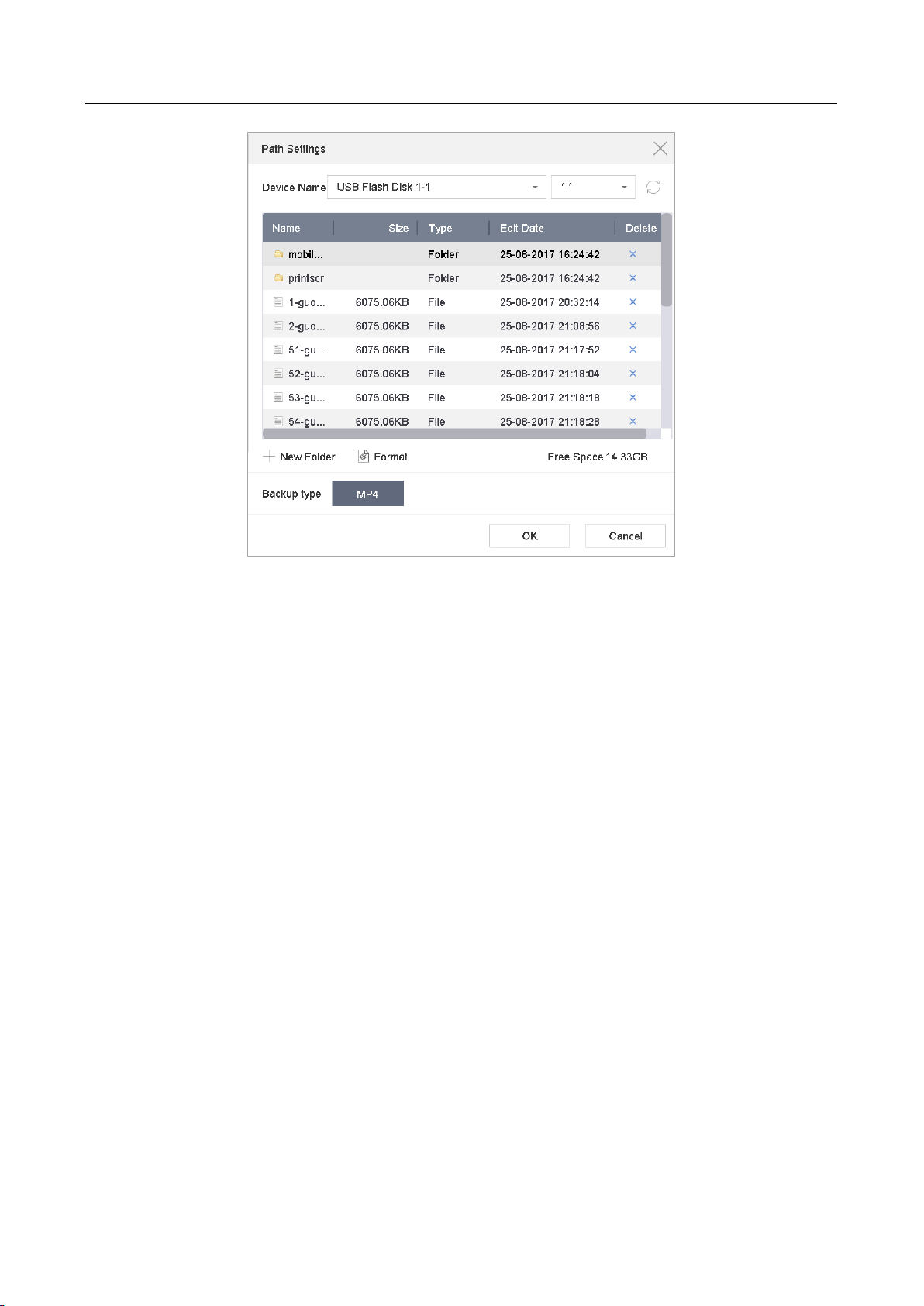
Network Video Recorder User Manual
88
Figure 9-4 Export Files
Click OK to export pictures to backup device.
9.3 Search History Operation
9.3.1 Save Search Condition
Purpose:
You can save the search conditions for future reference and quick search.
Step 1 Go to File Management > All Files/Human File/Vehicle File.
Step 2 Click Show More and set the search conditions.
Step 3 Click Save.
Step 4 Enter a name in text field and click Finished. The saved search conditions will be displayed in
search history list.
9.3.2 Call Search History
Purpose:
You can quickly search files by calling search history.
Step 1 Go to File Management > All Files/Human File/Vehicle File.
Step 2 Click a created search conditon to quickly search files.
Page 90

Network Video Recorder User Manual
89
Chapter 10 Playback
10.1 Playing Video Files
10.1.1 Instant Playback
Instant Playback enables the device to play the recorded video files in last five minutes. If no video
is found, it means there is no video during the last five minutes.
Step 1 On the live view window of the selected camera, move the cursor to the window bottom to
access the toolbar.
Step 2 Click to start instant playback.
Figure 10-1 Playback Interface
10.1.2 Play Video
Step 1 Go to Playback.
Step 2 Select one or more cameras in the camera list.
Step 3 Select a date in the calendar.
Step 4 You can use the toolbar in the bottom part of playback interface to control the playing and
realize a series of operations. Refer to Chapter 10.2 Playback Operations.
Page 91

Network Video Recorder User Manual
90
Figure 10-2 Playback Interface
Figure 10-3 Toolbar of Playback
Step 5 You can click the channel(s) to execute simultaneous playback of multiple channels.
The playing speed of 256X is supported.
10.1.3 Play Tag Files
Purpose:
Video tag allows you to record related information like people and location of a certain time point
during playback. You can use video tag(s) to search for video files and position time point.
Before playing back by tag:
Manage Tag Files
Step 1 Go to Playback.
Step 2 Search and play back the video file(s).
Step 3 Click to add the tag.
Step 4 Edit the tag information.
Page 92
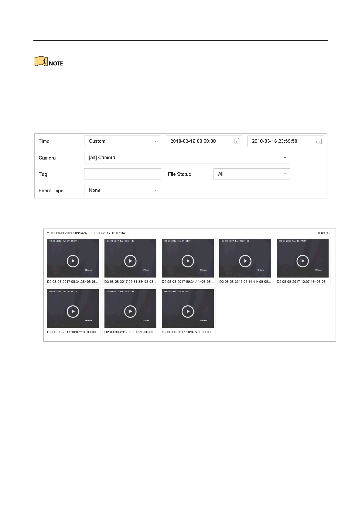
Network Video Recorder User Manual
91
Max. 64 tags can be added to a single video file.
Play Tag Files
Step 1 Go to File Management > All Files.
Step 2 Enter the search conditions for the tag files, including the time and the tag keyword.
Figure 10-4 Tag Search
Step 3 Click Search.
Figure 10-5 Searched Tag Files
Step 4 On the search results interface, select a tag file and click to start playing the video.
10.1.4 Play by Smart Search
Purpose
In the smart playback mode, the device will analyze the video containing the motion, line or
intrusion detection information, mark it with green color and play it in the normal speed. And the
video without motion will be played in 16X speed.
The smart playback rules and areas are configurable.
Page 93

Network Video Recorder User Manual
92
Step 1 Go to Playback.
Step 2 Start playing the video files by channel or by time.
Step 3 From the toolbar at the bottom of the playing window, click the motion/line crossing/ intrusion
icon for search.
Figure 10-6 Playback by Smart Search
Step 4 Set the rules and areas for smart search of line crossing detection, intrusion detection or
motion detection event triggered recording.
Line Crossing Detection
1) Click the icon.
2) Click on the image to specify the start point and end point of the line.
Intrusion Detection
3) Click the icon.
4) Specify 4 points to set a quadrilateral region for intrusion detection. Only one region can be set.
Motion Detection
5) Click the icon.
6) Hold the mouse on the image to draw the detection area manually.
7) Click Search to search the matched video and start to play it.
Page 94

Network Video Recorder User Manual
93
10.1.5 Play Event Files
Purpose
Play back video files on one or several channels searched by event type (e.g., alarm input, motion
detection, line crossing detection, face detection, vehicle detection, etc.).
Step 1 Go to Playback.
Step 2 Click Custom Search on the left bottom to enter the Search Condition interface.
Step 3 Enter the search conditions for the event files, e.g., time, event type, file status, people
appearance (for face detection, human detection, etc.), vehicle information (for vehicle
detection event).
Only DS-7700NXI series support face detection function.
Figure 10-7 Search Conditions
Step 4 Click Search.
Step 5 On the search results interface, select an event video file/picture file and click to start playing
the video or double click to play the picture.
Page 95

Network Video Recorder User Manual
94
Figure 10-8 Event Files
Step 6 You can click or button to select the previous or next event.
Refer to Chapter 11 Event and Alarm Settings and Chapter 12 VCA Event Alarm for details
for event and alarm settings.
Refer to Chapter 7.7 Configure Event Triggered Recording for the event triggered
recording/capture settings.
10.1.6 Play by Sub-periods
Purpose:
The video files can be played in multiple sub-periods simultaneously on the screens.
Step 1 Go to Playback.
Step 2 Select Sub-periods from the drop-down list in the upper-left corner of the page to enter the
Sub-periods Playback interface.
Step 3 Select a date and start playing the video file. Select the Split-screen Number from the
dropdown list. Up to 16 screens are configurable.
Page 96

Network Video Recorder User Manual
95
Figure 10-9 Interface of Sub-periods Playback
According to the defined number of split-screens, the video files on the selected date can be
divided into average segments for playback. E.g., if there are video files existing between 16:00 and
22:00, and the 6-screen display mode is selected, then it can play the video files for 1 hour on each
screen simultaneously.
10.1.7 Play Log Files
Purpose:
Play back record file(s) associated with channels after searching system logs.
Step 1 Go to Maintenance > Log Information.
Step 2 Click Log Search tab to enter Playback by System Logs.
Step 3 Set search time and type and click Search.
Page 97

Network Video Recorder User Manual
96
Figure 10-10 System Log Search Interface
Step 4 Choose a log with video file and click to start playing the log file.
Figure 10-11 Interface of Playback by Log
Page 98
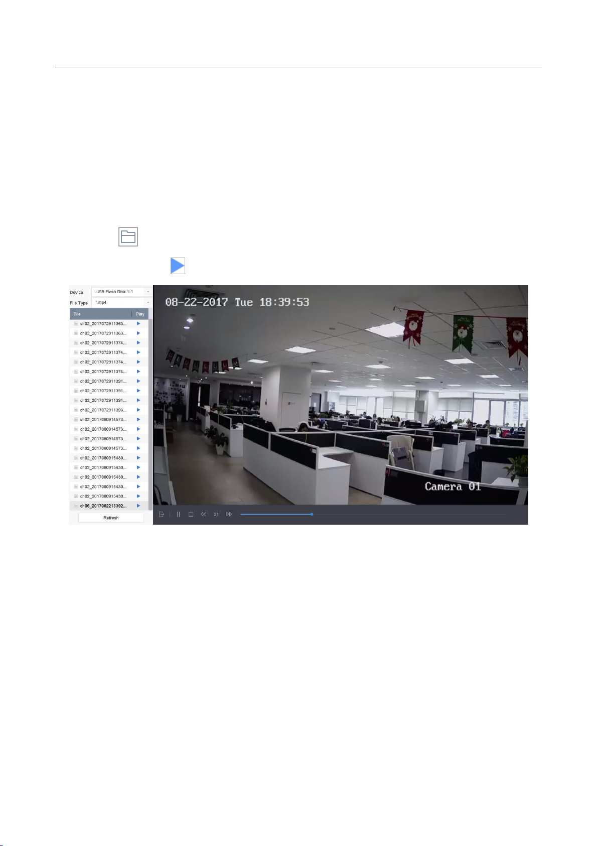
Network Video Recorder User Manual
97
10.1.8 Play External File
Purpose:
You can play files from the external storage devices.
Before You Start:
Connect the storage device with the video files to your device.
Step 1 Go to Playback.
Step 2 Click the icon at the left bottom corner.
Step 3 Select and click the button or double click to play the file.
Figure 10-12 External File Playback
10.2 Playback Operations
10.2.1 Normal/Important/Custom Video
During the playback, you can select the following three modes to play the video.
Normal: video files from the continuous recording.
Important: video files from the event and alarm recording triggered recording.
Custom: video files searched by custom conditions.
10.2.2 Set Play Strategy in Important/Custom Mode
Purpose:
Page 99

Network Video Recorder User Manual
98
When you are in the important or custom video playback mode, you can set the playing speed
separately for the normal video and the important/custom video, or you can select to skip the
normal video.
In the Important/Custom video playback mode, click to set the play strategy.
When Do not Play Normal Videos is checked, the device will skip the normal video and play
the important (event) video and the custom (searched video) only in the normal speed
(X1).
When Do not Play Normal Videos is unchecked, you can set the play speed for the normal
video the important/custom video separately. The speed range is from X1 to XMAX.
You can set the speed in the single-channel play mode only.
Figure 10-13 Play Strategy
10.2.3 Edit Video Clips
You can take video clips during the playback and export the clips.
In the video playback mode, click to start video clipping operation.
: Set the start time and end time of the video clipping.
: Export the video clips to the local storage device.
10.2.4 Switch between Main Stream and Sub-Stream
You can switch between the main stream and the sub-stream during the playback.
: Play the video in main stream.
Page 100
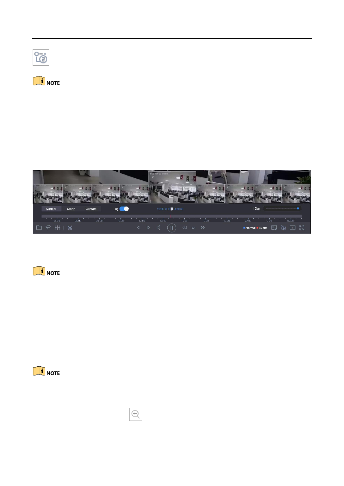
Network Video Recorder User Manual
99
: Play the video in sub-stream.
The encoding parameters for the main stream and sub-stream can be configured in Storage >
Encoding Parameters.
10.2.5 Thumbnails View
With the thumbnails view on the playback interface, you can conveniently locate the required
video files on the time bar.
In the video playback mode, move the mouse to the time bar to get the preview thumbnails of the
video files.
Figure 10-14 Thumbnails View
You can select and double click on a required thumbnail to enter the full-screen playback.
The thumbnail view is supported only in the 1X single-camera playback mode.
10.2.6 Fast View
You can hold the mouse to drag on the time bar to get the fast view of the video files.
In the video playback mode, use the mouse to hold and drag through the playing time bar to fast
view the video files.
Release the mouse to the required time point to enter the full-screen playback.
The fast view is supported only in the 1X single-camera playback mode.
10.2.7 Digital Zoom
In the video playback mode, click from the toolbar to enter the digital zoom interface.
 Loading...