

Hikvision DS-2TD2136-10-V1, DS-2TD2136-15-V1, DS-2TD2136-25-V1, DS-2TD2136-35-V1, DS-2TD2136-7-V1 Quick Start Guide
...Page 1

DS-2TD2xxx-xx/xx
Thermal and Optical Bi-Spectrum
Network Bullet Camera
Quick Start Guide
Page 2

DS-2TD2xxx-xx/xx Thermal and Optical Bi-Spectrum Network Bullet Camera Quick Start Guide
© 2020 Hangzhou Hikvision Digital Technology Co., Ltd. All rights reserved.
This Manual is the property of Hangzhou Hikvision Digital Technology Co., Ltd., or its affiliates (hereinafter
referred to as “Hikvision”), and it cannot be reproduced, changed, translated, or distributed, partially or
wholly, by any means, without the prior written permission of Hikvision. Unless otherwise expressly stated
herein, Hikvision does not make any warranties, guarantees, or representations, express or implied,
regarding to the Manual, any information contained herein.
About this Manual
The Manual includes instructions for using and managing the Product. Pictures, charts, images, and all
other information hereinafter are for description and explanation only. The information contained in the
Manual is subject to change, without notice, due to firmware updates or other reasons. Please find the
latest version of this Manual at the Hikvision Website (http://www.hikvision.com/en/).
Please use this Manual with the guidance and assistance of professionals trained in supporting the
Product.
Trademarks Acknowledgement
and other Hikvision trademarks and logos are the properties of Hikvision in various
jurisdictions.
Other trademarks and logos mentioned are the properties of their respective owners.
LEGAL DISCLAIMER
TO THE MAXIMUM EXTENT PERMITTED BY APPLICABLE LAW, THIS MANUAL AND THE PRODUCT DESCRIBED, WITH
ITS HARDWARE, SOFTWARE, AND FIRMWARE, ARE PROVIDED “AS IS” AND “WITH ALL FAULTS AND ERRORS.”
HIKVISION MAKES NO WARRANTIES, EXPRESS OR IMPLIED, INCLUDING WITHOUT LIMITATION, MERCHANTABILITY,
SATISFACTORY QUALITY, OR FITNESS FOR A PARTICULAR PURPOSE. THE USE OF THE PRODUCT BY YOU IS AT YOUR
OWN RISK. IN NO EVENT WILL HIKVISION BE LIABLE TO YOU FOR ANY SPECIAL, CONSEQUENTIAL, INCIDENTAL, OR
INDIRECT DAMAGES, INCLUDING, AMONG OTHERS, DAMAGES FOR LOSS OF BUSINESS PROFITS, BUSINESS
INTERRUPTION, OR LOSS OF DATA, CORRUPTION OF SYSTEMS, OR LOSS OF DOCUMENTATION, WHETHER BASED ON
BREACH OF CONTRACT, TORT (INCLUDING NEGLIGENCE), PRODUCT LIABILITY, OR OTHERWISE, IN CONNECTION WITH
THE USE OF THE PRODUCT, EVEN IF HIKVISION HAS BEEN ADVISED OF THE POSSIBILITY OF SUCH DAMAGES OR
LOSS.
YOU ACKNOWLEDGE THAT THE NATURE OF INTERNET PROVIDES FOR INHERENT SECURITY RISKS, AND HIKVISION
SHALL NOT TAKE ANY RESPONSIBILITIES FOR ABNORMAL OPERATION, PRIVACY LEAKAGE, OR OTHER DAMAGES
RESULTING FROM CYBER-ATTACK, HACKER ATTACK, VIRUS INSPECTION, OR OTHER INTERNET SECURITY RISKS;
HOWEVER, HIKVISION WILL PROVIDE TIMELY TECHNICAL SUPPORT IF REQUIRED.
YOU AGREE TO USE THIS PRODUCT IN COMPLIANCE WITH ALL APPLICABLE LAWS, AND YOU ARE SOLELY
RESPONSIBLE FOR ENSURING THAT YOUR USE CONFORMS TO THE APPLICABLE LAW. ESPECIALLY, YOU ARE
RESPONSIBLE, FOR USING THIS PRODUCT IN A MANNER THAT DOES NOT INFRINGE ON THE RIGHTS OF THIRD
PARTIES, INCLUDING WITHOUT LIMITATION, RIGHTS OF PUBLICITY, INTELLECTUAL PROPERTY RIGHTS, OR DATA
PROTECTION AND OTHER PRIVACY RIGHTS. YOU SHALL NOT USE THIS PRODUCT FOR ANY PROHIBITED END-USES,
INCLUDING THE DEVELOPMENT OR PRODUCTION OF WEAPONS OF MASS DESTRUCTION, THE DEVELOPMENT OR
PRODUCTION OF CHEMICAL OR BIOLOGICAL WEAPONS, ANY ACTIVITIES IN THE CONTEXT RELATED TO ANY NUCLEAR
EXPLOSIVE OR UNSAFE NUCLEAR FUEL-CYCLE, OR IN SUPPORT OF HUMAN RIGHTS ABUSES.
IN THE EVENT OF ANY CONFLICTS BETWEEN THIS MANUAL AND THE APPLICABLE LAW, THE LATTER PREVAILS.
QSG DS-2TD2xxx-xx/xx 071720NA 2
Page 3

DS-2TD2xxx-xx/xx Thermal and Optical Bi-Spectrum Network Bullet Camera Quick Start Guide
Regulatory Information
FCC Information
Please take attention that changes or modification not expressly approved by the party responsible for
compliance could void the user’s authority to operate the equipment.
FCC Compliance
This equipment has been tested and found to comply with the limits for Class A device, pursuant to part
15 of the FCC Rules. These limits are designed to provide reasonable protection against harmful
interference when the equipment is operated in a commercial environment. This equipment generates,
uses, and can radiate radio frequency energy and, if not installed and used in accordance with the
instruction manual, may cause harmful interference to radio communications. Operation of this
equipment in a residential area is likely to cause harmful interference in which case the user will be
required to correct the interference at his own expense.
FCC Conditions
This device complies with part 15 of the FCC Rules. Operation is subject to the following two conditions:
•
This device may not cause harmful interference.
•
This device must accept any interference received, including interference that may cause undesired
operation.
EU Conformity Statement
This product and, if applicable, the supplied accessories too are marked with “CE” and comply
therefore with the applicable harmonized European standards listed under the EMC Directive
2014/30/EU, the RoHS Directive 2011/65/EU.
2012/19/EU (WEEE Directive): Products marked with this symbol cannot be disposed of as
unsorted municipal waste in the European Union. For proper recycling, return this product to your
local supplier upon the purchase of equivalent new equipment, or dispose of it at designated
collection points. For more information see: www.recyclethis.info.
2006/66/EC (Battery Directive): This product contains a battery that cannot be disposed of as
unsorted municipal waste in the European Union. See the product documentation for specific
battery information. The battery is marked with this symbol, which may include lettering to
indicate cadmium (Cd), lead (Pb), or mercury (Hg). For proper recycling, return the battery to your
supplier or to a designated collection point. For more information see: www.recyclethis.info.
Industry Canada ICES-003 Compliance
This device meets the CAN ICES-3 (A)/NMB-3(A) standards requirements.
QSG DS-2TD2xxx-xx/xx 071720NA 3
Page 4

DS-2TD2xxx-xx/xx Thermal and Optical Bi-Spectrum Network Bullet Camera Quick Start Guide
Symbol
Description
Provides additional information to emphasize or supplement imp
ortant points of the
Indicates a potentially hazardous situation, which if not avoided, could result in
Indicates a hazard with a high level of ris
k, which if not avoided, will result in death or
Symbol Convention
The symbols that may be found in this document are defined as follows.
WARNING
DANGER
main text.
equipment damage, data loss, performance degradation, or unexpected results.
serious injury.
Safety Instruction
These instructions are intended to ensure that user can use the product correctly to avoid danger or
property loss.
Laws and Regulations
•
The lightning protection and grounding design of outdoor installation and wiring should be in
compliance with the lightning protection requirements of the buildings and local laws and regulations.
•
Use of the product must be in strict compliance with the local electrical safety regulations.
Storage
•
Store the device in a dry, well-ventilated, corrosive-gas-free, no direct sunlight, and no heating
source environment. Neglect may cause fire hazard.
•
To avoid heat accumulation, good ventilation is required for a proper operating environment.
•
DO NOT touch the heat dissipation component to avoid burns.
Transportation
•
Keep the device in original or similar packaging while transporting it.
•
Keep all wrappers after unpacking them for future use. In case any failure occurs, you need to return
the device to the factory with the original wrapper. Transportation without the original wrapper may
result in damage to the device, and the company shall not take any responsibilities.
•
DO NOT drop the product or subject it to physical shock. Keep the device away from magnetic
interference.
Installation
•
When the device is mounted on a wall or ceiling, the device shall be firmly fixed.
•
Avoid equipment installation on vibratory surface or places subject to shock (neglect may cause
equipment damage).
QSG DS-2TD2xxx-xx/xx 071720NA 4
Page 5

DS-2TD2xxx-xx/xx Thermal and Optical Bi-Spectrum Network Bullet Camera Quick Start Guide
Power Supply
•
Make sure that the power has been disconnected before you wire, install, or disassemble the device.
•
Input voltage should meet both the SELV (Safety Extra Low Voltage) and the Limited Power Source with
12 VDC, 24 VAC , or PoE (802.3af) according to the IEC60950-1 standard. Please refer to technical
specifications for detailed information.
•
Use a power adapter provided by a qualified manufacturer. Refer to the product specification for
detailed power requirements. It is recommended to provide an independent power adapter for each
device as adapter overload may cause overheating or a fire hazard.
Battery
•
DO NOT place the battery near a heating or fire source. Avoid direct sunlight.
•
Improper use or replacement of the battery may result in explosion hazard. Replace with the same or
equivalent type only. Dispose of used batteries according to the instructions provided by the battery
manufacturer.
•
For long-term storage of the battery, make sure it is fully charged every half year to ensure the battery
quality. Otherwise, damage may occur.
System Security
•
You acknowledge that the nature of the Internet provides for inherent security risks, and our company
shall not take any responsibilities for abnormal operation, privacy leakage, or other damages resulting
from cyber attack or hacker attack. However, our company will provide timely technical support if
required.
•
Please enforce protection for personal information and data security as the device may be confronted
with network security problems when it is connected to the Internet. Please contact us when the
device might incur network security risks.
•
Please understand that you have the responsibility to configure all the passwords and other security
settings about the device, and keep your user name and password.
Maintenance
•
Clean the lens with a soft and dry cloth or wiping paper to avoid scratching it.
•
If the product does not work properly, contact your dealer or the nearest service center. We shall not
assume any responsibility for problems caused by unauthorized repair or maintenance.
•
A few device components (e.g., electrolytic capacitor) require regular replacement. The average
lifespan varies, so periodic checking is recommended. Contact your dealer for details.
QSG DS-2TD2xxx-xx/xx 071720NA 5
Page 6

DS-2TD2xxx-xx/xx Thermal and Optical Bi-Spectrum Network Bullet Camera Quick Start Guide
Environment
•
DO NOT expose the device to extremely hot, cold, dusty, corrosive, saline-alkali, or damp
environments. Make sure the running environment meets the requirement of the device. The operating
temperature shall be -40° to 65° C (-40° to 149° F).
•
DO NOT aim the lens at the sun or any other bright light.
•
Keep the camera away from liquid while in use.
Emergency
•
If smoke, odor, or noise arises from the device, immediately turn off the power, unplug the power
cable, and contact the service center.
Device User Manual
Scan the QR code below to view the latest device user manual on your mobile phone. Note that mobile
data charges may apply if Wi-Fi is unavailable.
Figure 1, QR Code
QSG DS-2TD2xxx-xx/xx 071720NA 6
Page 7

DS-2TD2xxx-xx/xx Thermal and Optical Bi-Spectrum Network Bullet Camera Quick Start Guide
Table of Contents
Appearance Description ................................................................................................................................ 8
Type I Camera Appearance ........................................................................................................................... 8
Type II Camera Appearance ........................................................................................................................ 10
Type III Camera Appearance ....................................................................................................................... 10
Type IV Camera Appearance ....................................................................................................................... 11
Cable Description ........................................................................................................................................ 11
Junction Box Interfaces ............................................................................................................................. 12
Installation ................................................................................................................................................... 13
Install Memory Card ..................................................................................................................................... 14
Install Type I Camera Memory Card ................................................................................................... 14
Install Type II and Type IV Camera Memory Card ............................................................................... 16
Install Type III Camera Memory Card .................................................................................................. 16
Wide Range Coverage ................................................................................................................................. 17
Install Camera ............................................................................................................................................. 18
2.3.1 Install Type I Camera .......................................................................................................................... 18
Install Type II and Type IV Camera ..................................................................................................... 20
Install Type III Camera ........................................................................................................................ 22
Waterproof Measures (Optional) ................................................................................................................ 25
2.4.1 Install Network Cable Waterproof Jacket ......................................................................................... 26
Waterproof Other Cables ................................................................................................................... 26
Set the Network Camera over the LAN ......................................................................................................... 27
Wiring ........................................................................................................................................................... 27
Activate the Camera ................................................................................................................................... 27
Activate via Web Browser .................................................................................................................. 27
Activate via SADP Software ............................................................................................................... 28
Modify the IP Address ................................................................................................................................. 29
Access via Web Browser .............................................................................................................................. 30
Appendix ...................................................................................................................................................... 32
Common Material Emissivity Reference .................................................................................................... 32
QSG DS-2TD2xxx-xx/xx 071720NA 7
Page 8
DS-2TD2xxx-xx/xx Thermal and Optical Bi-Spectrum Network Bullet Camera Quick Start Guide
Bullet Type
Model
Type I
DS-
2TD2235D
-25
Type II
DS-
2TD2637
-
10/P
Type III
DS-
2TD2836
-
25/V1
Type IV
DS-2TD2617
-
3/PA
Appearance Description
There are four thermal and optical bi-spectrum network bullet camera types. Here are overviews of Type I
cameras, Type II cameras, Type III cameras, and Type IV cameras.
DS-2TD2235D-50
DS-2TD2637-15/P
DS-2TD2637-25/P
DS-2TD2637-35/P
DS-2TD2836-50/V1
DS-2TD2866-25/V1
DS-2TD2866-50/V1
DS-2TD2617-6/PA
DS-2TD2617-10/PA
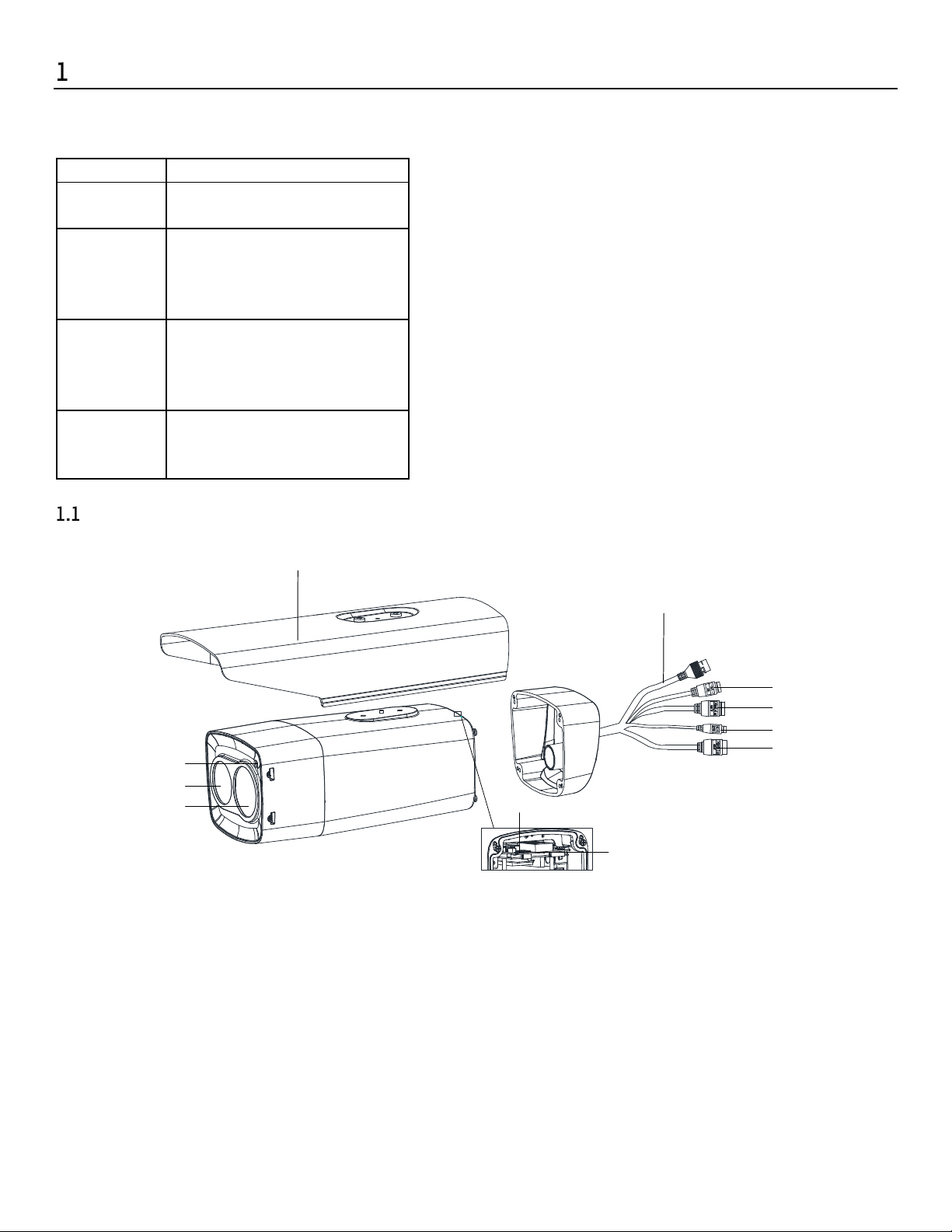
Type I Camera Appearance
4
5
6
7
8
9
1
2
3
Figure 2, Type I Camera Appearance (1)
11
10
QSG DS-2TD2xxx-xx/xx 071720NA 8
Page 9
DS-2TD2xxx-xx/xx Thermal and Optical Bi-Spectrum Network Bullet Camera Quick Start Guide
No. Description
No. Description
1 Photoresister
2
Lens
(Optical)
3 Lens (Thermal)
4
Sun Shield
5 Network Cable
6
Power
Supply Interface
7 Alarm Interface
8 RS-
485
9 Audio Interface
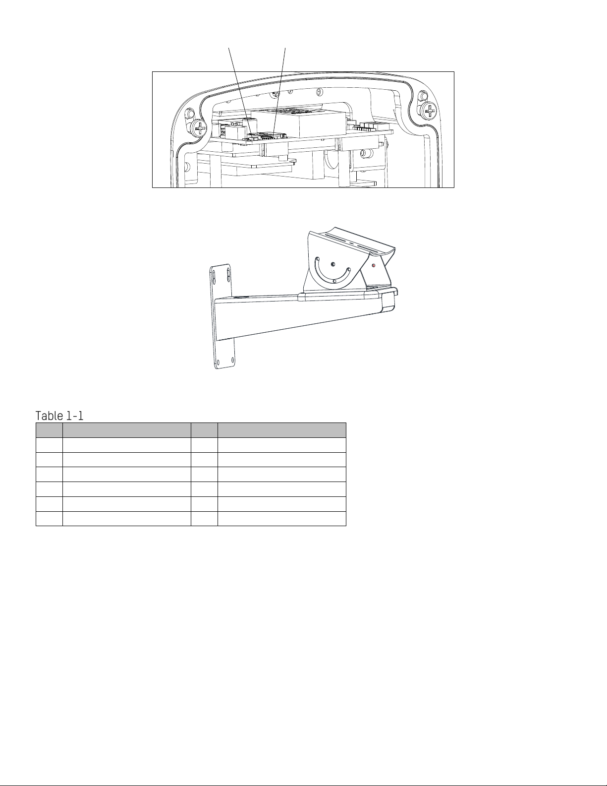
10 MicroSD
Card
11 Reset
11
10
Figure 3, Type I Camera Appearance (2)
Figure 4, Wall Mounting Bracket (Optional)
Description
QSG DS-2TD2xxx-xx/xx 071720NA 9
Page 10
DS-2TD2xxx-xx/xx Thermal and Optical Bi-Spectrum Network Bullet Camera Quick Start Guide
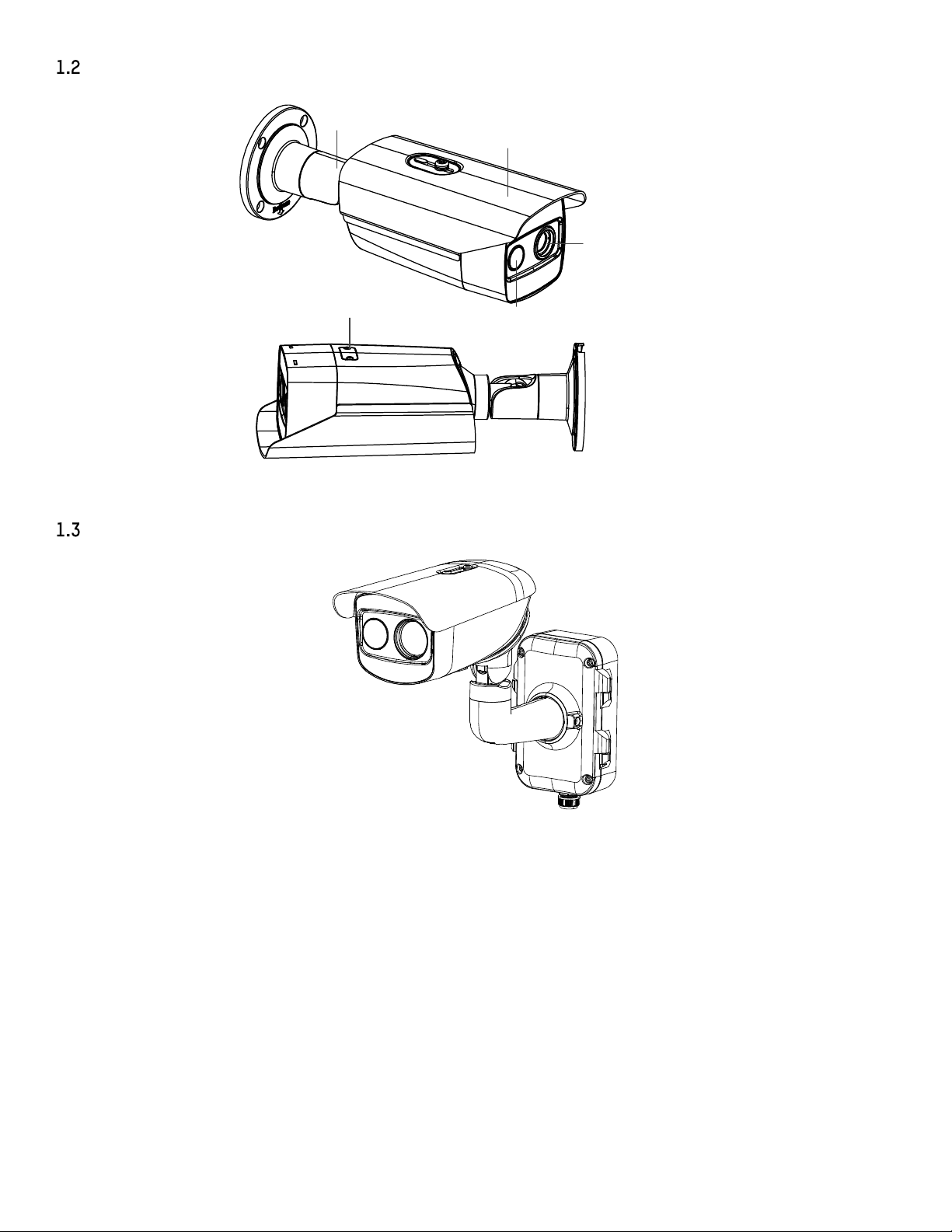
Type II Camera Appearance
Mount
Sun Shield
Thermal Lens
Type III Camera Appearance
Memory Card
Optical Lens
Figure 5, Type II Camera Appearance
Figure 6, Type III Camera Appearance
QSG DS-2TD2xxx-xx/xx 071720NA 10
Page 11

DS-2TD2xxx-xx/xx Thermal and Optical Bi-Spectrum Network Bullet Camera Quick Start Guide
Sun Shield
Bracket Holder
Cable Outlet
Sealing Interface
Type IV Camera Appearance
Bracket
Camera
Bracket Hinge
Bracket Arm
Junction Box Cover
Junction Box Base
Figure 7, Type III Camera Cables
Sun Shield
Speaker
Memory Card Slot
Reset Button
Reset Button
Memory Card
Slot
Thermal Lens
White Light
Lamp
Optical Lens
Figure 8, Type IV Camera Appearance
Cable Description
The bullet camera cables, including power cable, alarm cable, and audio cable are shown as figure below.
The cable is provided for certain camera models. Refer to the actual device.
QSG DS-2TD2xxx-xx/xx 071720NA 11
Page 12

DS-2TD2xxx-xx/xx Thermal and Optical Bi-Spectrum Network Bullet Camera Quick Start Guide
Name
Description
For 12 VDC or 24 VAC power supply, make sure that the positive/negative te
rminals
Network Interface
Connect to the LAN interf
ace. PoE (802.3af) is supported
Two
-
way alarm input
and alarm output are supported
Audio In: Pickup
RS-485 Interface
Control line
Audio Output Interface
Audio Input Interface
Alarm Interface 1
Alarm Interface 2
RS-485 Interface
Power Interface (12 VDC)
Network Interface
Audio Output Interface
Audio Input Interface
Alarm Interface 1
Alarm Interface 2
RS-485 Interface
Power Interface (12 VDC or 24 VAC)
Network Interface
Figure 9, Cable Description
Cable Description
Power Interface
Alarm Interface
are connected correctly
Alarm In: IN1, G/IN2, and G
Alarm Out: 1A, 1B/2A, and 2B
Audio Interface
Audio Out: Loudspeaker
The cables may vary by model. Here we list all cable types for reference. See the actual
product for the cables.
Alarm cables can be classified as 2-ch alarm inputs and 2-ch alarm outputs. ALARM-IN1 and
ALARM-IN2 are alarm input interfaces, and G indicates grounding interface. (1A, 1B) and (2A,
2B) indicate two alarm output interfaces.
To reset the camera to default parameters, hold the Reset button and power on the camera.
After powering on the camera, continue to hold the Reset button for about 10 seconds.
Junction Box Interfaces
For certain camera models, the power cable, alarm cable, network cable, and audio cable are connected
to the junction box interfaces. Refer to the figure below for connections.
QSG DS-2TD2xxx-xx/xx 071720NA 12
Page 13

DS-2TD2xxx-xx/xx Thermal and Optical Bi-Spectrum Network Bullet Camera Quick Start Guide
The junction box differs by camera model.
Alarm Interface
Audio Input& Output Interface
Network Interface
Power Interface
Figure 10, Interface Description
Installation
Before You Start
•
Make sure the device in the package is in good condition and all the assembly parts are included.
•
The standard power supply is 12 VDC, 24 VAC, or PoE (802.3af). Make sure your power supply matches
your camera.
•
Make sure all the related devices are powered off during the installation.
•
Check the specification of the products for the installation environment.
•
Make sure that the wall is strong enough to withstand four times the weight of the camera and the
bracket.
For cameras that support IR, pay attention to the following precautions to prevent IR reflection:
•
Dust or grease on the camera cover will cause IR reflection. DO NOT remove the camera cover film until
the installation is finished. If there is dust or grease on the camera cover, clean the camera cover with
a clean soft cloth and isopropyl alcohol.
•
Make sure that there is no reflective surface too close to the camera lens. The IR light from the camera
may reflect back into the lens causing reflection.
•
DO NOT drag the camera with its waterproof cables, or the waterproof performance will be affected.
QSG DS-2TD2xxx-xx/xx 071720NA 13
Page 14

DS-2TD2xxx-xx/xx Thermal and Optical Bi-Spectrum Network Bullet Camera Quick Start Guide
Install Memory Card
Install Type I Camera Memory Card
1. Unscrew and remove the sun shield.
Sun
Shield
Figure 11, Remove Sun Shield
Screws
2. Unscrew and remove the back cover.
QSG DS-2TD2xxx-xx/xx 071720NA 14
Page 15

DS-2TD2xxx-xx/xx Thermal and Optical Bi-Spectrum Network Bullet Camera Quick Start Guide
Figure 12, Remove Back Cover Case
3. Insert a microSD card into the microSD card slot.
Figure 13, Insert MicroSD Card
4. Fix the sun shield and back cover to the camera body with the removed screws.
Figure 14, Figure 1-1 Fix Sun Shield and Back Cover
QSG DS-2TD2xxx-xx/xx 071720NA 15
Page 16

DS-2TD2xxx-xx/xx Thermal and Optical Bi-Spectrum Network Bullet Camera Quick Start Guide
Install Type II and Type IV Camera Memory Card
Type II and Type IV camera memory cards are installed in the same way. Here is an example of memory card
installation for a Type II camera.
1. Unscrew and remove the memory card slot cover.
Figure 15, Remove Card Slot Cover
2. Insert a microSD card into the microSD card slot until the card clicks.
Figure 16, Insert MicroSD Card
3. Cover the memory card slot, and fix the screws on the memory card slot cover.
Install Type III Camera Memory Card
1. Unscrew the memory card slot cover and remove it.
QSG DS-2TD2xxx-xx/xx 071720NA 16
Page 17

DS-2TD2xxx-xx/xx Thermal and Optical Bi-Spectrum Network Bullet Camera Quick Start Guide
Lens (
Focal Length
) 3 mm
6 mm
7 mm 10 mm 15 mm 25 mm 35 mm
Detection
Range
(Vehicles)
280 m
559 m
631 m
902 m
1353 m
2255 m
3157 m
Detection
Range
(Humans)
91 m
182 m
206 m
294 m
441 m
735 m
1029 m
Recognition
Range
(Vehicles)
70 m
140 m
158 m
225 m
338 m
564 m
789 m
Recognition
Range
(Humans)
23 m
46 m
51 m
74 m
110 m
184 m
257 m
Identification
Range
(Vehicles)
35 m
70 m
79 m
113 m
169 m
282 m
395 m
Identification
Range
(Huma
ns) 11 m
23 m
26 m
37 m
55 m
92 m
129 m
Memory Card Cover
D
D
D
D
R
R
R
R
A
A
A
A
C
C
C
C
D
D
D
D
S
S
S
S
Figure 17, Remove Card Slot Cover
2. Insert the memory card into the memory card slot.
Memory Card
Figure 18, Insert Memory Card
3. Cover the memory card slot and fix the screws on the memory card slot cover.
Wide Range Coverage
Select the installation location and proper lens focal length according to the Wide Range Coverage list
below:
Wide Range Coverage
Take human as 0.5 m (width) × 1.8 m (height), and limit length is 0.75 m. The vehicle limit length is 2.3 m.
QSG DS-2TD2xxx-xx/xx 071720NA 17
Page 18

DS-2TD2xxx-xx/xx Thermal and Optical Bi-Spectrum Network Bullet Camera Quick Start Guide
•
Detect Target: The target should be at least 1.5 pixels on the image.
•
Recognize Target: The target should be at least 6 pixels on the image.
•
Identify Target: The target should be at least 12 pixels on the image.
This table is for reference only, and the actual detection range may vary due to camera
settings, mounting condition, monitor, etc.
Install Camera
2.3.1 Install Type I Camera
1. Fix the bullet camera with mounting bracket with expansion screws or bolts, as shown below.
Bolts
Figure 19, Install the Bracket onto the Wall
2. Fix the bullet camera to the mounting bracket with the supplied screws, as shown below.
Bolts
Figure 20, Fix the Camera to the Bracket
3. Bolt the camera body to the bracket.
QSG DS-2TD2xxx-xx/xx 071720NA 18
Page 19

DS-2TD2xxx-xx/xx Thermal and Optical Bi-Spectrum Network Bullet Camera Quick Start Guide
Figure 21, Fix the Camera to the Wall
4. Adjust the camera to the optimal surveillance angle.
1) Loosen the pan adjusting screw to adjust panning position [0° to 360°]. Tighten the screw.
Panning Position [0° to 360°]
Figure 22, Pan Adjustment
2) Loosen the tile adjusting screw to adjust the tilting position [-45° to 45°]. Tighten the screw.
QSG DS-2TD2xxx-xx/xx 071720NA 19
Page 20

DS-2TD2xxx-xx/xx Thermal and Optical Bi-Spectrum Network Bullet Camera Quick Start Guide
Tilting Position [-45° to 45°]
Figure 23, Tilt Adjustment
Loosen the screws slightly until you can adjust the camera. DO NOT remove the screws from
the bracket.
Install Type II and Type IV Camera
Type II and Type IV cameras are installed in the same way. Here is an example of installation for a Type II
camera.
Select a location, and attach the drill template onto the wall/ceiling, as shown below.
Figure 24, Drill Template
2. (Optional) For concrete walls, drill four Ø5 installation holes according to the template (recommended
depth: 25 mm) and insert the expansion screws. Otherwise, skip the step.
3. Drill a cable hole in the center.
QSG DS-2TD2xxx-xx/xx 071720NA 20
Page 21

DS-2TD2xxx-xx/xx Thermal and Optical Bi-Spectrum Network Bullet Camera Quick Start Guide
4. Install the bullet camera with the screws (supplied).
Figure 25, Wall/Ceiling Mounting
5. Adjust the camera to the optimal surveillance angle.
• Bracket Type I
1) Loosen the tilt adjusting screw to adjust tilting position [0° to 360°]. Tighten the screw.
2) Loosen the pan adjusting screw to adjust the panning position [-45° to 45°]. Tighten the screw.
3) Loosen the rotation adjusting screw to rotate the camera [0° to 360°]. Tighten the screw.
Figure 26, 3-Axis Adjustment
• Bracket Type II
1) Loosen the screw to adjust the tilting position [0° to 90°]. Tighten the screw.
2) Loosen the screw to adjust the rotation position [0° to 360°]. Tighten the screw.
QSG DS-2TD2xxx-xx/xx 071720NA 21
Page 22

DS-2TD2xxx-xx/xx Thermal and Optical Bi-Spectrum Network Bullet Camera Quick Start Guide
Screw
0°-90°
0°-360°
Figure 27, 2-Axis Adjustment
Install Type III Camera
Before You Start
There are three Type III camera installation methods: wall mounting, ceiling mounting, and stand
mounting.
Wall Mounting Ceiling Mounting Stand Mounting
Figure 28, Type III Camera Installation Methods
Loosen the screws on the junction box cover.
Draw the latches from the latch hole of the junction box and take apart the cover from the junction
box.
QSG DS-2TD2xxx-xx/xx 071720NA 22
Page 23

DS-2TD2xxx-xx/xx Thermal and Optical Bi-Spectrum Network Bullet Camera Quick Start Guide
Latch Holes
Latches
Figure 29, Take Apart Junction Box
Attach the drill template (supplied) to where you want to affix the camera, and then drill four screw
holes (recommended depth: 40 mm) in the ceiling/wall according to the drill template.
Drill a cable hole according to the A mark of the drill template.
Ф 10 mm
(0.39'')
Ф 24 mm
(0.94'')
Figure 30, Drill Template
Align the drill template hole with the junction box base screw hole to place the junction box onto the
wall.
Route the screw through the sealing ring, and fix the junction box base on the wall with the screws.
QSG DS-2TD2xxx-xx/xx 071720NA 23
Page 24

DS-2TD2xxx-xx/xx Thermal and Optical Bi-Spectrum Network Bullet Camera Quick Start Guide
Sealing Ring
Screw
Figure 31, Install Junction Box Base
Route the cables through the cable hole.
Insert the latches into the latch holes to fix the bracket and camera with the junction box.
Wall Mounting Ceiling Mounting Stand Mounting
Figure 32, Install Junction Box Cover
Fix the delivered screws to secure the junction box.
Connect the corresponding cables to power on the camera and get the live view.
Adjust the camera according to the figure below.
1) Loosen the rotation adjusting screw to rotate the camera [-180° to 180°]. Tighten the screw.
Rotation
Adjusting Screw
Rotation Range
[-180° to +180°]
Figure 33, R-Axis Adjustment
2) Loosen the tilt adjusting screw to adjust tilting position [-90° to 55°]. Tighten the screw.
QSG DS-2TD2xxx-xx/xx 071720NA 24
Page 25

DS-2TD2xxx-xx/xx Thermal and Optical Bi-Spectrum Network Bullet Camera Quick Start Guide
Tilting Adjusting
Screw
Tilting Range
[-90° to +55°]
Figure 34, T-Axis Adjustment
3) Loosen the pan adjusting screw to adjust the panning position [-90° to 90°]. Tighten the screw.
Panning
Adjusting Screw
Panning Range
[-90° to +90°]
Figure 35, P-Axis Adjustment
Waterproof Measures (Optional)
Purpose
If the camera is installed outdoors, use the waterproof accessory or tapes to waterproof the cables.
Otherwise the cables might get wet and a short circuit might occur.
QSG DS-2TD2xxx-xx/xx 071720NA 25
Page 26

DS-2TD2xxx-xx/xx Thermal and Optical Bi-Spectrum Network Bullet Camera Quick Start Guide
2.4.1 Install Network Cable Waterproof Jacket
⑥
③
①
Align
④
②
⑥
③
④
⑤
①
Figure 36, Install Waterproof Jacket
Feed the network cable through ① and ③ in order.
Fix ② on the network cable between ① and ③.
Place ⑤ onto the end of ⑥, and plug the RJ-45 male connector into RJ-45 female connector.
Screw ③ to ⑥ clockwise.
Push ② into ③.
Secure ① with the ③ in clockwise direction.
Waterproof Other Cables
After routing and connecting the cables, use the waterproof tape to wrap up the cables. Connected
cables and spare cables both should be wrapped up as the figures below.
Figure 37, Waterproof Cables
QSG DS-2TD2xxx-xx/xx 071720NA 26
Page 27

DS-2TD2xxx-xx/xx Thermal and Optical Bi-Spectrum Network Bullet Camera Quick Start Guide
Set the Network Camera over the LAN
You shall acknowledge that the use of the product with Internet access might be under
network security risks. For avoidance of any network attacks and information leakage,
please strengthen your own protection. If the product does not work properly, please
contact with your dealer or the nearest service center.
Wiring
Please connect the camera to the network according to the following figures.
Figure 38, Connect Directly
Figure 39, Connect via a Switch or a Router
Activate the Camera
You must activate the camera first by setting a strong password for it before you can use the camera.
Activation via Web Browser, Activation via SADP, and Activation via Client Software are all supported. We
will take activation via SADP software and Activation via a Web Browser as examples to introduce camera
activation. Refer to the network camera user manual for activation via client software.
Activate via Web Browser
Power on the camera, and connect the camera to the network.
Input the IP address into the Web browser’s address bar, and click Enter to enter the activation
interface.
The camera’s default IP address is 192.168.1.64.
For cameras that enable DHCP by default, activate the camera via SADP software and search
for the IP address.
QSG DS-2TD2xxx-xx/xx 071720NA 27
Page 28

DS-2TD2xxx-xx/xx Thermal and Optical Bi-Spectrum Network Bullet Camera Quick Start Guide
Figure 40, Activation Interface (Web)
Create a password and input it into the password field.
STRONG PASSWORD RECOMMENDED − We highly recommend that you create a strong password
of your own choosing (using a minimum of eight characters, including at least three of the
following categories: upper case letters, lower case letters, numbers, and special
characters) in order to increase the security of your product. We also recommend that you
reset your password regularly. Especially in high security systems, resetting the password
monthly or weekly can better protect your product.
Proper configuration of all passwords and other security settings is the responsibility of the
installer and/or end-user.
Confirm the password.
Click OK to save the password and enter the live view interface.
Activate via SADP Software
SADP software is used to detect the online device, activate the camera, and reset the password.
Get the SADP software from the supplied disk or the official Website, and install it according
to the prompts. Follow the steps to activate the camera. Refer to the network camera user
manual for the other two activation methods.
Run the SADP software to search the online devices.
Check the device status from the device list, and select the inactive device.
QSG DS-2TD2xxx-xx/xx 071720NA 28
Page 29

DS-2TD2xxx-xx/xx Thermal and Optical Bi-Spectrum Network Bullet Camera Quick Start Guide
Figure 41, SADP Interface
The SADP software supports activating the camera in batch. Refer to the SADP software user
manual for details.
Create a password, input the password in the password field, and confirm the password.
STRONG PASSWORD RECOMMENDED − We highly recommend that you create a strong password
of your own choosing (using a minimum of eight characters, including at least three of the
following categories: upper case letters, lower case letters, numbers, and special
characters) in order to increase the security of your product. We also recommend that you
reset your password regularly. Especially in high security systems, resetting the password
monthly or weekly can better protect your product.
Proper configuration of all passwords and other security settings is the responsibility of the
installer and/or end-user.
4. Click OK.
5. Check whether the activation is completed on the pop-up window. If activation failed, make sure that
the password meets the requirement and try again.
Modify the IP Address
Purpose
To view and configure the camera via a LAN (Local Area Network), you need to connect the network
camera in the same subnet with your PC. Then, install the SADP software or client software to search and
change the network camera’s IP address. We will take modifying the IP address via SADP software as an
example to introduce IP address modification.
Run the SADP software.
Select an active device.
Refer to Chapter 3.2 to activate the camera if the camera is inactive.
QSG DS-2TD2xxx-xx/xx 071720NA 29
Page 30

DS-2TD2xxx-xx/xx Thermal and Optical Bi-Spectrum Network Bullet Camera Quick Start Guide
Change the device IP address to the same subnet as your computer by either modifying the IP address
manually or checking Enable DHCP.
Figure 42, Modify the IP Address
Input the password to activate your IP address modification.
Batch IP address modification is supported by SADP. Refer to the SADP user manual for
details.
Access via Web Browser
System Requirements:
• Operating System: Microsoft Windows XP SP1 and above version
• CPU: 2.0 GHz or higher
• RAM: 1 GB or higher
• Display: 1024×768 resolution or higher
• Web Browser: Internet Explorer 8.0 or above version, Apple Safari 5.0.2 or above version, Mozilla Firefox
5.0 or above version, or Google Chrome 18 or above version
QSG DS-2TD2xxx-xx/xx 071720NA 30
Page 31

DS-2TD2xxx-xx/xx Thermal and Optical Bi-Spectrum Network Bullet Camera Quick Start Guide
Open the Web browser.
Input the IP address of the network camera in the browser address bar, and press Enter to enter the
login interface.
The default IP address is 192.168.1.64.
If the camera is not activated, activate the camera first according to Chapter 3.2.
Input the user name and password.
The admin user should configure the device accounts and user/operator permissions
properly. Delete unnecessary accounts and user/operator permissions.
The device IP address locks if the admin user performs seven failed password attempts (five
attempts for users/operators).
Click Login.
Figure 43, Login Interface
Install the plug-in before viewing the live video and managing the camera. Follow the installation
prompts to install the plug-in.
Close the Web browser to finish the installation of the plug-in.
Figure 44, Download Plug-in
Reopen the Web browser after the installation of the plug-in and repeat steps 2-4 to login.
For further detailed configuration instructions, refer to the network camera user manual.
QSG DS-2TD2xxx-xx/xx 071720NA 31
Page 32

DS-2TD2xxx-xx/xx Thermal and Optical Bi-Spectrum Network Bullet Camera Quick Start Guide
Material
Emissivity
Human Skin
0.98
PCB 0.91
Cement Concrete
0.95
Ceramics
0.92
Rubber
0.95
Paint
0.93
Wood
0.85
Asphalt
0.96
Brick
0.95
Sand
0.90
Soil
0.92
Cotton
0.98
Cardboard
0.90
White Paper
0.90
Water
0.96
Appendix
Common Material Emissivity Reference
QSG DS-2TD2xxx-xx/xx 071720NA 32
 Loading...