

Page 1

PanoVu Series Camera
Quick Start Guide
UD01546B
Page 2

i
PanoVu Series Camera·Quick Start Guide
Quick Start Guide
COPYRIGHT © 2016 Hangzhou Hikvision Digital Technology Co., Ltd.
ALL RIGHTS RESERVED.
Any and all information, including, among others, wordings, pictures, graphs are the properties of
Hangzhou Hikvision Digital Technology Co., Ltd. or its subsidiaries (hereinafter referred to be
“Hikvision”). This user manual (hereinafter referred to be “the Manual”) cannot be reproduced,
changed, translated, or distributed, partially or wholly, by any means, without the prior written
permission of Hikvision. Unless otherwise stipulated, Hikvision does not make any warranties,
guarantees or representations, express or implied, regarding to the Manual.
About this Manual
This Manual is applicable to PanoVu Series Camera.
The Manual includes instructions for using and managing the product. Pictures, charts, images and
all other information hereinafter are for description and explanation only. The information
contained in the Manual is subject to change, without notice, due to firmware updates or other
reasons. Please find the latest version in the company website (http://overseas.hikvision.com/en/).
Please use this user manual under the guidance of professionals.
Trademarks Acknowledgement
jurisdictions. Other trademarks and logos mentioned below are the properties of their respective
owners.
Legal Disclaimer
TO THE MAXIMUM EXTENT PERMITTED BY APPLICABLE LAW, THE PRODUCT DESCRIBED, WITH ITS
HARDWARE, SOFTWARE AND FIRMWARE, IS PROVIDED “AS IS”, WITH ALL FAULTS AND ERRORS,
AND HIKVISION MAKES NO WARRANTIES, EXPRESS OR IMPLIED, INCLUDING WITHOUT LIMITATION,
MERCHANTABILITY, SATISFACTORY QUALITY, FITNESS FOR A PARTICULAR PURPOSE, AND
NON-INFRINGEMENT OF THIRD PARTY. IN NO EVENT WILL HIKVISION, ITS DIRECTORS, OFFICERS,
EMPLOYEES, OR AGENTS BE LIABLE TO YOU FOR ANY SPECIAL, CONSEQUENTIAL, INCIDENTAL, OR
INDIRECT DAMAGES, INCLUDING, AMONG OTHERS, DAMAGES FOR LOSS OF BUSINESS PROFITS,
BUSINESS INTERRUPTION, OR LOSS OF DATA OR DOCUMENTATION, IN CONNECTION WITH THE
USE OF THIS PRODUCT, EVEN IF HIKVISION HAS BEEN ADVISED OF THE POSSIBILITY OF SUCH
DAMAGES.
REGARDING TO THE PRODUCT WITH INTERNET ACCESS, THE USE OF PRODUCT SHALL BE WHOLLY
AT YOUR OWN RISKS. HIKVISION SHALL NOT TAKE ANY RESPONSIBILITES FOR ABNORMAL
OPERATION, PRIVACY LEAKAGE OR OTHER DAMAGES RESULTING FROM CYBER ATTACK, HACKER
ATTACK, VIRUS INSPECTION, OR OTHER INTERNET SECURITY RISKS; HOWEVER, HIKVISION WILL
PROVIDE TIMELY TECHNICAL SUPPORT IF REQUIRED.
SURVEILLANCE LAWS VARY BY JURISDICTION. PLEASE CHECK ALL RELEVANT LAWS IN YOUR
JURISDICTION BEFORE USING THIS PRODUCT IN ORDER TO ENSURE THAT YOUR USE CONFORMS
THE APPLICABLE LAW. HIKVISION SHALL NOT BE LIABLE IN THE EVENT THAT THIS PRODUCT IS USED
WITH ILLEGITIMATE PURPOSES.
IN THE EVENT OF ANY CONFLICTS BETWEEN THIS MANUAL AND THE APPLICABLE LAW, THE LATER
PREVAILS.
and other Hikvision’s trademarks and logos are the properties of Hikvision in various
Page 3
ii
PanoVu Series Camera·Quick Start Guide
Regulatory Information
FCC Information
FCC compliance: This equipment has been tested and found to comply with the limits for a Class A
digital device, pursuant to part 15 of the FCC Rules. These limits are designed to provide reasonable
protection against harmful interference when the equipment is operated in a commercial
environment. This equipment generates, uses, and can radiate radio frequency energy and, if not
installed and used in accordance with the instruction manual, may cause harmful interference to
radio communications. Operation of this equipment in a residential area is likely to cause harmful
interference in which case the user will be required to correct the interference at his own expense.
FCC Conditions
This device complies with part 15 of the FCC Rules. Operation is subject to the following two
conditions:
1. This device may not cause harmful interference.
2. This device must accept any interference received, including interference that may cause
undesired operation
EU Conformity Statement
This product and - if applicable - the supplied accessories too are marked with "CE"
and comply therefore with the applicable harmonized European standards listed
under the EMC Directive 2014/30/EU, the RoHS Directive 2011/65/EU.
2012/19/EU (WEEE directive): Products marked with this symbol cannot be disposed of
as unsorted municipal waste in the European Union. For proper recycling, return this
product to your local supplier upon the purchase of equivalent new equipment, or
www.recyclethis.info.
collection point. For more information see: www.recyclethis.info.
Industry Canada ICES-003 Compliance
This device meets the CAN ICES-3 (A)/NMB-3(A) standards requirements.
dispose of it at designated collection points. For more information see:
2006/66/EC (battery directive): This product contains a battery that cannot be disposed
of as unsorted municipal waste in the European Union. See the product
documentation for specific battery information. The battery is marked with this
symbol, which may include lettering to indicate cadmium (Cd), lead (Pb), or mercury
(Hg). For proper recycling, return the battery to your supplier or to a designated
Page 4
iii
Warnings Follow these
safeguards to prevent serious
injury or death.
Cautions Follow these
precautions to prevent
potential injury or material
damage.
PanoVu Series Camera·Quick Start Guide
Safety Instruction
These instructions are intended to ensure that user can use the product correctly to avoid danger
or property loss.
The precaution measure is divided into Warnings and Cautions:
Warnings: Neglecting any of the warnings may cause serious injury or death.
Cautions: Neglecting any of the cautions may cause injury or equipment damage.
Warnings
All the electronic operation should be strictly compliance with the electrical safety regulations,
fire prevention regulations and other related regulations in your local region.
Please use the power adapter, which is provided by normal company. For standard of the power
adapter, please refer to the specification manual for details. The power consumption cannot be
less than the required value.
Do not connect several devices to one power adapter as adapter overload may cause over-heat
or fire hazard.
Please make sure that the power has been disconnected before you wire, install or dismantle the
panoVu camera.
When the product is installed on wall or ceiling, the device shall be firmly fixed.
If smoke, odors or noise rise from the device, turn off the power at once and unplug the power
cable, and then please contact the service center.
If the product does not work properly, please contact your dealer or the nearest service center.
Never attempt to disassemble the panoVu camera yourself. (We shall not assume any
responsibility for problems caused by unauthorized repair or maintenance.)
The output of the use of external power supply should meet Limited Power Source according to
the IEC 60905-1 standard.
Cautions
Do not drop the camera or subject it to physical shock, and do not expose it to high
electromagnetism radiation. Avoid the equipment installation on vibrations surface or places
subject to shock (ignorance can cause equipment damage).
Do not place the camera in extremely hot, cold, dusty or damp locations, otherwise fire or
electrical shock will occur. For working temperature, please refer to the specification manual for
details.
The camera cover for indoor use shall be kept from rain and moisture.
Page 5

iv
PanoVu Series Camera·Quick Start Guide
Exposing the equipment to direct sun light, low ventilation or heat source such as heater or
radiator is forbidden (ignorance can cause fire danger).
Do not aim the panoVu camera at the sun or extra bright places. A blooming or smear may occur
otherwise (which is not a malfunction however), and affecting the endurance of sensor at the
same time.
Please use the provided glove when open up the camera cover, avoid direct contact with the
camera cover, because the acidic sweat of the fingers may erode the surface coating of the
camera cover.
Please use a soft and dry cloth when clean inside and outside surfaces of the camera cover, do
not use alkaline detergents.
Please keep all wrappers after unpack them for future use. In case of any failure occurred, you
need to return the panoVu camera to the factory with the original wrapper. Transportation
without the original wrapper may result in damage on the panoVu camera and lead to additional
costs.
Page 6

v
PanoVu Series Camera·Quick Start Guide
Table of Contents
1 Installation ................................................................................................... 6
1.1 Connecting Cables .................................................................................................................... 6
1.2 Alarm Input and Output Connection ........................................................................................ 7
2 Mounting Application .................................................................................. 8
2.1 Installing the Bracket ................................................................................................................ 8
2.1.1 Installing the Wall Mounting Bracket ................................................................................. 8
2.1.2 Installing the Hoop Mounting Bracket ............................................................................... 9
2.2 Installing the PanoVu Camera ................................................................................................. 11
2.2.1 Installing the 180° Panoramic + PTZ Camera ................................................................... 11
2.2.2 Installing the 360° Panoramic + PTZ Camera ................................................................... 13
2.2.3 Installing the 360° Panoramic Camera ............................................................................. 16
3 Setting the Camera Over the LAN ............................................................... 19
3.1 Wiring .................................................................................................................................... 19
3.2 Activating the PanoVu camera ................................................................................................ 19
3.2.1 Activation via Web Browser ............................................................................................. 19
3.2.2 Activation via SADP Software .......................................................................................... 20
3.3 Modifying the IP Address ....................................................................................................... 21
4 Accessing via Web browser ........................................................................ 23
Page 7
6
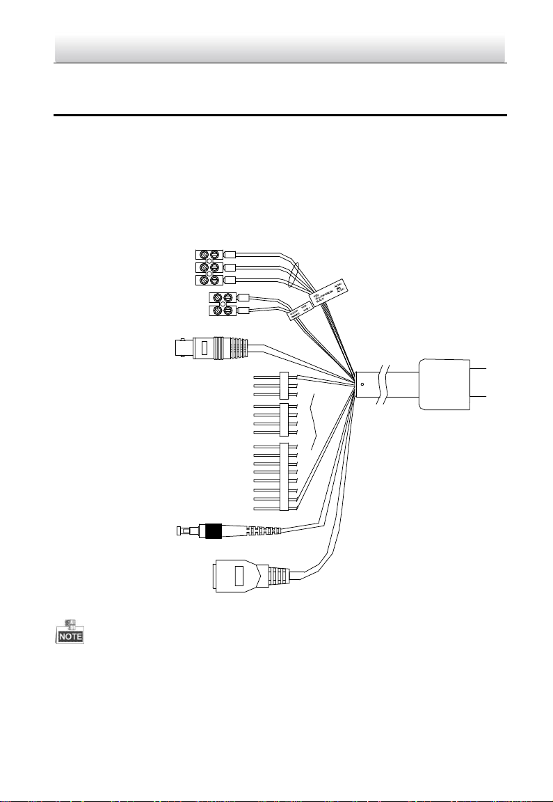
VIDEO
RED 36VDC +
BLACK 36VDC -
GND
RS485-
RS485+
CVBS Video Cable
Alarm Inputs
Network Cable
Alarm Outputs
Audio Input / Output
Optical FC Interface
PanoVu Series Camera·Quick Start Guide
1 Installation
Warning: Do not power the panoVu camera up until the installation is finished. To ensure the safety
of personnel and equipment, all the installation steps should be done with power supply off.
1.1 Connecting Cables
The cable interfaces of PanoVu camera are shown in Figure 1-1. The cables of RS-485, power supply,
alarm inputs, alarm outputs, video output, etc. are distinguished by different colors. Please refer to
the labels attached on the cables for identification.
The cables may vary according to the models.
Use the power adapter that can work normally at an altitude over 5000 meters above sea
level.
Figure 1-1 Cables of PanoVu Series Camera
Page 8
7
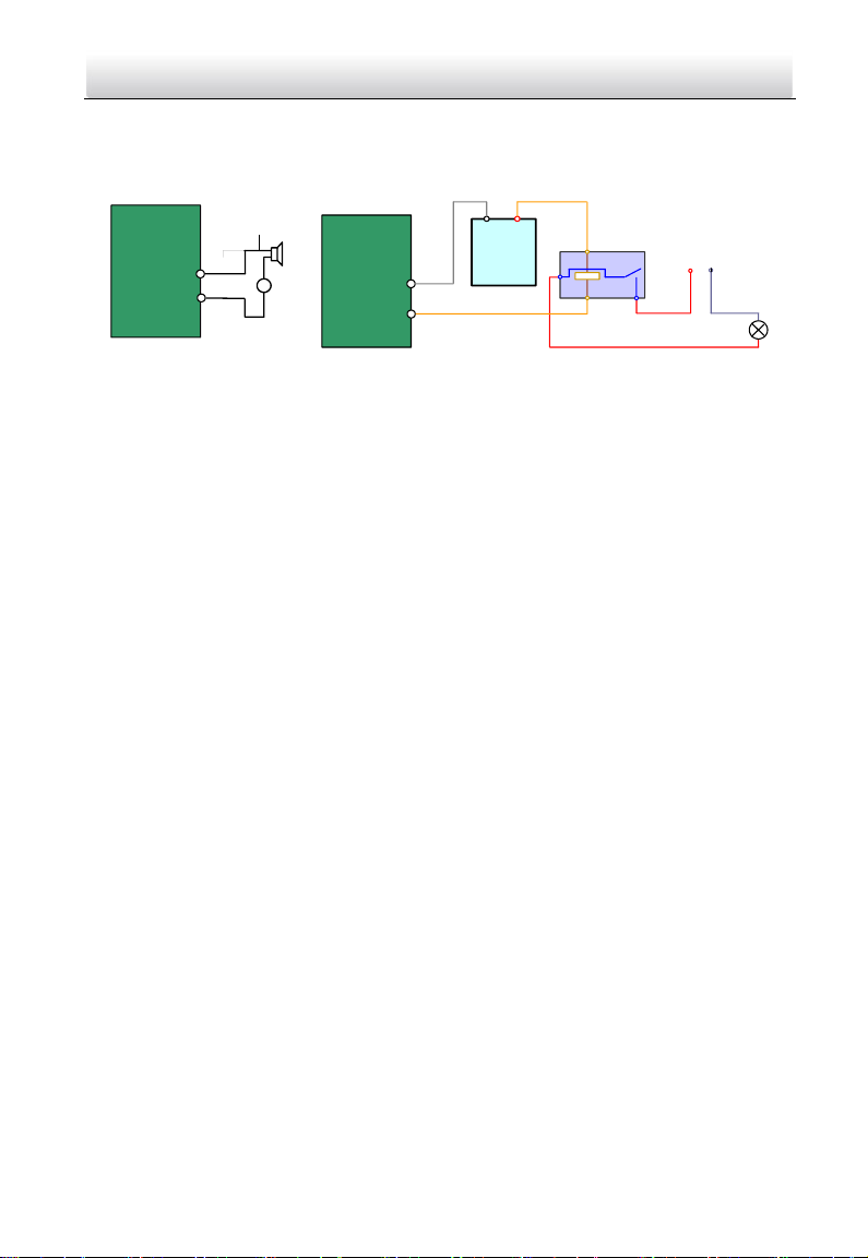
JQC-
3FG
Relay
30VDC
GND OUT
L N
~
220V AC
Relay Output
Dome
( 10A 250VAC)
Diagram (left) Diagram(right)
1A
OUT(n)
OUT(n)
+
-
DC
DC Load
Relay Output
Dome
OUT(n)
OUT(n)
PanoVu Series Camera·Quick Start Guide
1.2 Alarm Input and Output Connection
The network camera can be connected with alarm inputs (0~5VDC)
Refer to the following diagrams for alarm output:
Figure 1-2 Alarm Out Connections
The alarm provides the relay output, and the external power supply is required when it connects to
the alarm device.
For DC power supply (left diagram), the input voltage must be no more than 30VDC, 1A.
For AC power supply, the external relay must be used (right diagram) to prevent damages to
the camera and avoid risk of electric shock.
Page 9

8
PanoVu Series Camera·Quick Start Guide
2 Mounting Application
Before you start:
For cement wall, you need to use the expansion screw to fix the bracket. The mounting hole of
the expansion pipe on the wall should align with the mounting hole on the bracket.
For wooden wall, you can just use the self-tapping screw to fix the bracket.
The wall must be thick enough to install the expansion screws.
Please make sure that the wall is strong enough to withstand more than 8 times the weight of
the camera and the bracket.
2.1 Installing the Bracket
The wall mounting bracket is suitable for 4+1 PanoVu Camera, as shown in 2.1.1. For 7+1 PanoVu
Camera and 8+1 PanoVu Camera, please use the hoop mounting bracket, as shown in 2.1.2.
2.1.1 Installing the Wall Mounting Bracket
When you select a thread bracket, please install the pendent adapter (supplied) between the
bracket and PanoVu Camera. Any mismatch problems shall be taken responsibility by the
user.
The dimension of pendant adapter is G1
For cement wall, you need to use the expansion screw to fix the bracket.
For wooden wall, you can just use the self-tapping screw to fix the bracket.
Please make sure that the wall is strong enough to withstand at least 8 times the weight of
the camera and the bracket.
The wall must be thick enough to mount the expansion screws.
There are several ways to install the PanoVu Camera. In this section, the non-thread bracket
installation is taken as an example. Refer to the following steps for details:
Steps:
1. Get the bracket and screws from the packing box as shown follows.
1
.
2
Figure 1-3 Wall Mounting Bracket and Accessories
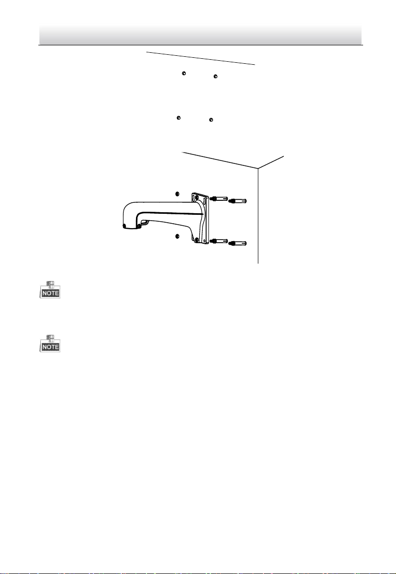
2. Drill 4 φ9 screw holes in the wall according to the hole locations of the bracket, and then
insert M8 expansion screws into the screw holes.
Page 10
9
PanoVu Series Camera·Quick Start Guide
Figure 1-4 Drill Screw Hole and Insert Expansion Screw
3. Secure the bracket with 4 hex nuts and washers.
Figure 1-5 Drill Screw Holes
Please take water-proof measures when installing outdoor PanoVu Camera.
2.1.2 Installing the Hoop Mounting Bracket
The pole for mounting the PanoVu Camera should be suitable for the hoop.
The diameter of the hoop ranges from 67mm to 127mm (2.64’ to 5’).
Please make sure that the pole is strong enough to withstand at least 8 times the weight of
the camera and the bracket.
There are several ways to install the PanoVu Camera. In this section, the installation on horizontal
pole with hoop is taken as an example. Refer to the following steps for details:
Steps:
1. Get the bracket and accessories from the packing box as shown follows.
Page 11

10
Hoop
Bracket
Pendent
Bracket
Towards the Ground
Fixing Plate
Hoop Bracket
Pendent Bracket
PanoVu Series Camera·Quick Start Guide
Figure 1-6 Hoop Bracket and Pendent Bracket
2. Fix the hoop to the pole by adjusting the hoop according to the pole, as shown in Figure 1-7.
Figure 1-7 Drill Hole and Insert Expansion Screws
3. Fix the hoop bracket with the pendent bracket.
1) Route the cables through the pendent mounting bracket.
2) Attach the fixing plate of the hoop bracket to the flange plate of the pendent bracket by
aligning the screw holes.
3) Fix the two brackets with four screws, flat washer and spring washer, as shown in Figure 1-8.
Figure 1-8 Assemble the Hoop Bracket and Pendent Bracket
Page 12

11
Protective
Foam
Lens Cover
Lower Dome
Back Box
Sticker
PanoVu Series Camera·Quick Start Guide
2.2 Installing the PanoVu Camera
The appearance of PanoVu camera may vary according to the models. The appearance shown
below is only for reference.
2.2.1 Installing the 180° Panoramic + PTZ Camera
Steps:
1. Loosen the two lock screws on the both side of the camera. Pull the lower camera to
separate it from the back box as shown in Figure 1-9.
Please do not remove the lock screws from the camera.
Figure 1-9 Remove the Lower Camera
2. Remove the protective foam, sticker and lens cover from the camera drive. As shown in
Figure 1-10.
Figure 1-10 Remove the Sticker
3. Install the micro SD card.
The Micro SD card slot of network camera is shown in Figure 1-11. Insert the matched micro SD
card until the card slot clicks.
Page 13

12
Head Cover
Camera
Main Body
①
②
③
Lock Screws
PanoVu Series Camera·Quick Start Guide
Figure 1-11 Micro SD Card Slot
4. Separate the head cover from the camera main body, as shown in Figure 1-12.
Figure 1-12 Head Cover of PanoVu Camera
5. Install the head cover of PanoVu camera.
1) Loosen the two lock screws and make sure that the screws do not appear in the inner side of
bracket, as shown in Figure 1-13.
2) Route the cables through the head cover and insert the head cover into the bottom of the
bracket.
3) Fix the head cover with the bracket by rotating the head cover clockwise or anticlockwise.
4) Fix two lock screws with the Allen wrench to secure the camera.
Figure 1-13 Installing Head Cover of PanoVu Camera
6. After fixing the head cover, hook the two ends of the safety rope to the bracket and the
camera respectively, as shown in Figure 1-14.
Page 14

13
VIEOD
Safety Rope
PanoVu Series Camera·Quick Start Guide
Figure 1-14 Install the Safety Rope
7. Connect all cables and insert the rest cables into the bracket.
8. Fix the PanoVu camera with the head cover by fixing screws of the head cover and bracket,
as shown in Figure 1-15.
Figure 1-15 Fix the PanoVu Camera
2.2.2 Installing the 360° Panoramic + PTZ Camera
Steps:
1. Loosen the two lock screws on the both side of the camera. Pull the lower camera to
separate it from the back box as shown in Figure 1-16.
Please do not remove the lock screws from the camera.
Page 15

14
Protective
Foam
Lens Cover
Lower Dome
Back Box
Sticker
PanoVu Series Camera·Quick Start Guide
Figure 1-16 Remove the Lower Camera
2. Remove the protective foam, sticker and lens cover from the camera drive. As shown in
Figure 1-17.
Figure 1-17 Remove the Sticker
3. Install the micro SD card.
The Micro SD card slot of network camera is shown in Figure 1-18. Insert the matched micro SD
card until the card slot clicks.
Figure 1-18 Micro SD Card Slot
4. Separate the head cover from the camera main body, as shown in Figure 1-19.
Page 16

15
Head Cover
Camera
Main Body
Lock Screws
VIEOD
Safety Rope
PanoVu Series Camera·Quick Start Guide
Figure 1-19 Head Cover of PanoVu Camera
5. Install the head cover of PanoVu camera.
1) Loosen the two lock screws and make sure that the screws do not appear in the inner side of
bracket, as shown in Figure 1-20.
2) Route the cables through the head cover and insert the head cover into the bottom of the
bracket.
3) Fix the head cover with the bracket by rotating the head cover clockwise or anticlockwise.
4) Fix two lock screws with the Allen wrench to secure the camera.
Figure 1-20 Installing Head Cover of PanoVu Camera
6. After fixing the head cover, hook the two ends of the safety rope to the bracket and the
camera respectively, as shown in Figure 1-21.
Figure 1-21 Install the Safety Rope
Page 17

16
VIEOD
Open the SD Card Slot
PanoVu Series Camera·Quick Start Guide
7. Connect all cables and insert the rest cables into the bracket.
8. Fix the PanoVu camera with the head cover by fixing screws of the head cover and bracket,
as shown in Figure 1-22.
Figure 1-22 Fix the PanoVu Camera
2.2.3 Installing the 360° Panoramic Camera
Steps:
1. Get the camera from the package, as shown in Figure 1-23.
Figure 1-23 7+1 PanoVu Camera
2. Install the micro SD card.
1) Loosen two screws and take apart the cover to release the micro SD card slot, as shown in
Figure 1-24.
Figure 1-24 Open the micro SD Card Slot
Page 18

17
Safety Rope
PanoVu Series Camera·Quick Start Guide
2) Insert the matched micro SD card until the card slot clicks.
3) Put the cover back on the camera.
3. Install the head cover of PanoVu camera.
1) Loosen the two lock screws and make sure that the screws do not appear in the inner side of
bracket, as shown in Figure 1-25.
2) Route the cables through the head cover and insert the head cover into the bottom of the
bracket.
3) Fix the head cover with the bracket by rotating the head cover clockwise or anticlockwise.
4) Fix two lock screws with the Allen wrench to secure the camera.
Figure 1-25 Installing Head Cover of PanoVu Camera
4. After fixing the head cover, hook the two ends of the safety rope to the bracket and the
camera respectively, as shown in Figure 1-26.
Figure 1-26 Install the Safety Rope
5. Connect all cables and insert the rest cables into the bracket.
6. Fix the PanoVu camera with the head cover by fixing screws of the head cover and bracket,
as shown in Figure 1-27.
Page 19

18
PanoVu Series Camera·Quick Start Guide
Figure 1-27 Fix the PanoVu Camera
Page 20

19
Network
Speed Dome
Switch
Internet
NVR
PC
PanoVu Series Camera·Quick Start Guide
3 Setting the Camera Over the LAN
You shall acknowledge that the use of the product with Internet access might be under network
security risks. For avoidance of any network attacks and information leakage, please strengthen
your own protection. If the product does not work properly, please contact with your dealer or
the nearest service center.
3.1 Wiring
To view and configure the panoVu camera via LAN (Local Area Network), you need to connect the
network panoVu camera in the same subnet with your PC. Then, install the SADP or client software
to search and change the IP of network panoVu camera.
The following figure shows the cable connection of network panoVu camera.
Figure 3-1 Wiring Over a LAN
3.2 Activating the PanoVu camera
Purpose:
You are required to activate the panoVu camera first by setting a strong password for it before you
can use the panoVu camera.
Activation via Web Browser, Activation via SADP, and Activation via client software are supported. In
the following sections, activation via web browser and SADP will be taken as examples. You may
refer to the user manual of the panoVu camera for the details of activation via client software.
3.2.1 Activation via Web Browser
Steps:
1. Power on the panoVu camera, and connect the panoVu camera to the network.
2. Input the IP address into the address bar of the web browser, and click Enter to enter the
activation interface.
Page 21

20
PanoVu Series Camera·Quick Start Guide
The default IP address of the panoVu camera is 192.168.1.64.
Figure 3-2 Activation Interface(Web)
3. Create a password and input the password into the password field.
STRONG PASSWORD RECOMMENDED–We highly recommend you create a strong
password of your own choosing (Using a minimum of 8 characters, including at least
three of the following categories: upper case letters, lower case letters, numbers, and
special characters.) in order to increase the security of your product. And we
recommend you reset your password regularly, especially in the high security system,
resetting the password monthly or weekly can better protect your product.
4. Confirm the password.
5. Click OK to activate the panoVu camera and enter the live view interface.
3.2.2 Activation via SADP Software
SADP software is used for detecting the online device, activating the device, and resetting the
password.
Get the SADP software from the supplied disk or the official website, and install the SADP according
to the prompts. Follow the steps to activate the panoVu camera.
Steps:
1. Run the SADP software to search the online devices.
2. Check the device status from the device list, and select an inactive device.
Page 22

21
PanoVu Series Camera·Quick Start Guide
Figure 3-3 SADP Interface
3. Create a password and input the password in the password field, and confirm the password.
STRONG PASSWORD RECOMMENDED–We highly recommend you create a strong
password of your own choosing (Using a minimum of 8 characters, including at least
three of the following categories: upper case letters, lower case letters, numbers, and
special characters.) in order to increase the security of your product. And we
recommend you reset your password regularly, especially in the high security system,
resetting the password monthly or weekly can better protect your product.
4. Click OK to save the password.
You can check whether the activation is completed on the popup window. If activation failed,
please make sure that the password meets the requirement and then try again.
3.3 Modifying the IP Address
Purpose:
To view and configure the panoVu camera via LAN (Local Area Network), you need to connect the
network panoVu camera in the same subnet with your PC. Then, install the SADP software or client
software to search and change the IP of network panoVu camera. We will take modifying the IP
Address via SADP software as an example to introduce the IP address modification.
Steps:
1. Run the SADP software.
2. Click to select an active device.
Please refer to the section 3.2 Activating the PanoVu camera to activate the panoVu
camera if it is inactive.
Page 23

22
PanoVu Series Camera·Quick Start Guide
3. Change the device IP address to the same subnet with your computer by either modifying the
IP address manually or checking the checkbox of Enable DHCP.
Figure 3-4 Modify the IP Address
4. Input the password and click Save to activate your IP address modification.
Page 24

23
PanoVu Series Camera·Quick Start Guide
4 Accessing via Web browser
System Requirement:
Operating System: Microsoft Windows XP SP1 and above version / Vista / Win7 / Server 2003 /
Server 2008 32bits
CPU: Intel Pentium IV 3.0 GHz or higher
RAM: 1G or higher
Display: 1024×768 resolution or higher
Web Browser: Internet Explorer 8.0 and above version, Apple Safari 5.02 and above version, Mozilla
Firefox 5 and above version and Google Chrome18 and above version
Steps:
1. Open the web browser.
2. In the browser address bar, input the IP address of the network panoVu camera, e.g.,
192.168.1.64 and press the Enter key to enter the login interface.
3. Activate the panoVu camera for the first time using, refer to the section 3.2 Activating the
PanoVu camera.
4. Input the user name and password and click .
The device IP address gets locked if the admin user performs 7 failed password attempts (5
attempts for the user/operator).
Figure 4-1 Login Interface
5. Install the plug-in before viewing the live video and managing the network panoVu camera.
Please follow the installation prompts to install the plug-in.
You may have to close the web browser to finish the installation of the plug-in.
Page 25

24
PanoVu Series Camera·Quick Start Guide
Figure 4-2 Download Plug-in
Figure 4-3 Install Plug-in
6. Reopen the web browser after the installation of the plug-in and repeat the above steps 2-4 to
login.
For detailed instructions of further configuration, please refer to the user manual of network
panoVu camera.
0503151061101
Page 26

25
PanoVu Series Camera·Quick Start Guide
 Loading...