

HIKVISION DS-2CS58C2P-S/F, DS-2CS58C2P-ITS/F, DS-2CS58C2P-ITS/C, DS-2CS58C2PN-S/F, DS-2CS58C2PN-ITS/F User Manual
...Page 1
Mobile Turret Camera
User Manual
UD00719B
User Manual
Thank you for purchasing our product. If there are any
questions, or requests, please do not hesitate to
contact the dealer.
This manual applies to the models below:
Type
Model
Type I Camera
DS-2CS58C2P(N)-S/F
Type II Camera
DS-2CS58C2P(N)-ITS/F
Type III Camera
DS-2CS58C2P(N)-ITS/C
This manual may contain several technical incorrect
places or printing errors, and the content is subject to
change without notice. The updates will be added to
the new version of this manual. We will readily improve
or update the products or procedures described in the
manual.
0100001060301
Page 2
Privacy Notice
Surveillance laws vary by jurisdiction. Check all relevant
laws in your jurisdiction before using all this product for
surveillance purpose to ensure that your use of this
product conforms.
Regulatory Information
FCC Information
FCC compliance: This equipment has been tested and
found to comply with the limits for a digital device,
pursuant to part 15 of the FCC Rules. These limits are
designed to provide reasonable protection against
harmful interference when the equipment is operated
in a commercial environment. This equipment
generates, uses, and can radiate radio frequency energy
and, if not installed and used in accordance with the
instruction manual, may cause harmful interference to
radio communications. Operation of this equipment in a
residential area is likely to cause harmful interference in
which case the user will be required to correct the
interference at his own expense.
FCC Conditions
This device complies with part 15 of the FCC Rules.
Operation is subject to the following two conditions:
1. This device may not cause harmful interference.
2. This device must accept any interference received,
including interference that may cause undesired
operation
EU Conformity Statement
This product and - if applicable - the
supplied accessories too are marked with
"CE" and comply therefore with the
applicable harmonized European
standards listed under the Low Voltage Directive
2014/35/EU, the EMC Directive 2014/30/EU.
2002/96/EC (WEEE directive): Products
marked with this symbol cannot be
disposed of as unsorted municipal waste in
the European Union. For proper recycling,
return this product to your local supplier
upon the purchase of equivalent new equipment, or
dispose of it at designated collection points. For more
information see: www.recyclethis.info.
2006/66/EC (battery directive): This
product contains a battery that cannot be
disposed of as unsorted municipal waste in
the European Union. See the product
documentation for specific battery
information. The battery is marked with
this symbol, which may include lettering to indicate
cadmium (Cd), lead (Pb), or mercury (Hg). For proper
recycling, return the battery to your supplier or to a
designated collection point. For more information see:
www.recyclethis.info.
Industry Canada ICES-003 Compliance
This device meets the CAN ICES-3 (A)/NMB-3(A)
standards requirements.
Page 3
1 Introduction
1.1 Product Features
This series of camera adopts high performance sensor and advanced circuit board design technology. It features high
resolution, low distortion, and low noise, etc. It is suitable for surveillance system and image process system.
Advanced 3-axis design
meets different installation
requirements;
High performance CMOS
sensor and high resolution
bring high-quality image;
Low illumination, 0.1
Lux @ (F1.2, AGC ON), 0
Lux with IR;
Build-in microphone;
Aviation plug design;
1.2 Overview
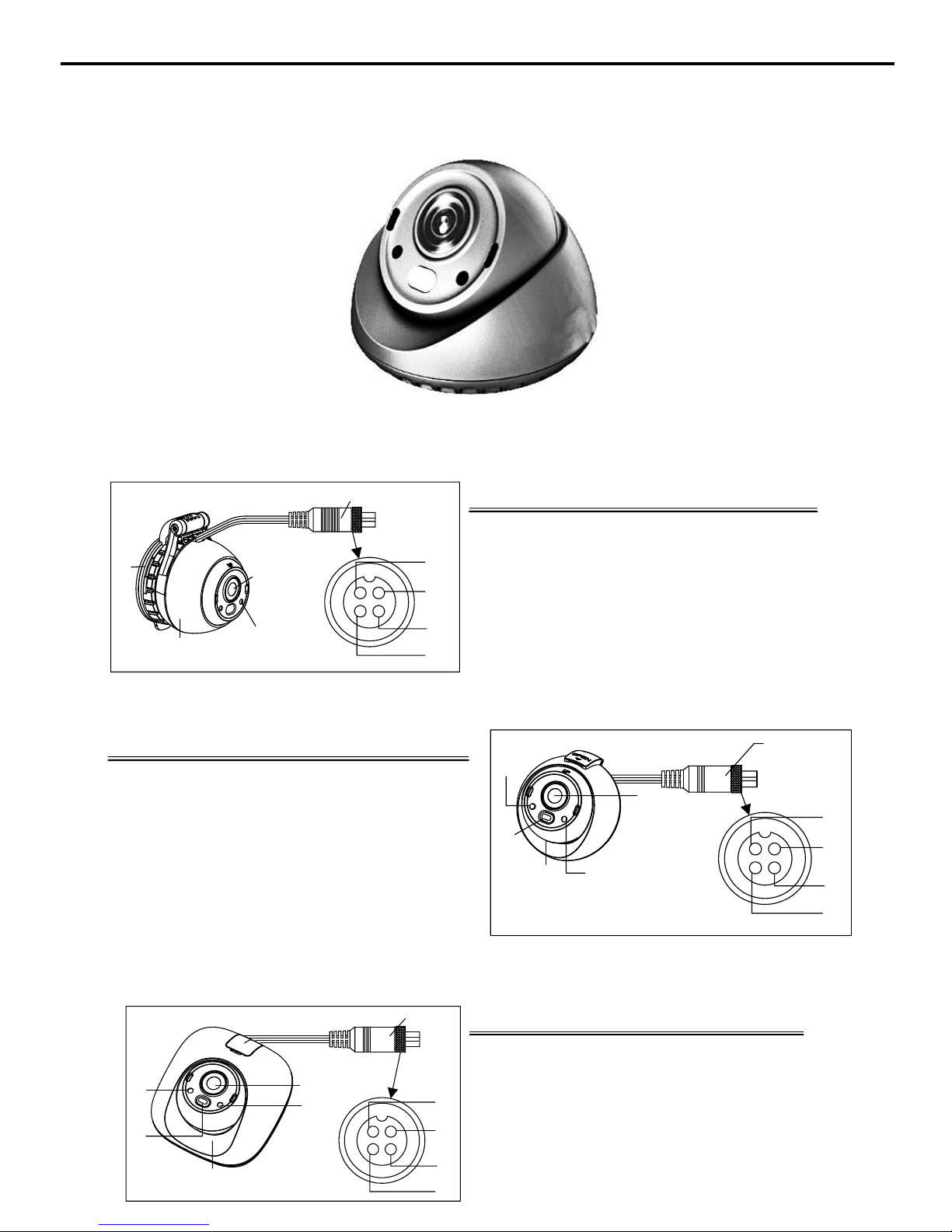
1.2.1 Overview of Type I Camera
1. Suction Mounting Base
2. Main Body
3. Aviation Plug
4. Lens
5. Microphone
A: CVBS
B: GND
C: AUDIO
D: POWER
A
D
B
C
1
2
3
4
5
Description of Type I Camera
1 4
2 3
1.2.2 Overview of Type II Camera
1. Photosensitive Resistor
2. IR LED
3. Main Body
4. Microphone
5. Lens
6. Aviation Plug
A: CVBS
B: GND
C: AUDIO
D: POWER
A
1
2
3
4
5
Description of Type II Camera
6
D
B
C
1 4
2 3
1.2.3 Overview of Type III Camera
1. Photosensitive Resistor
2. IR LED
3. Main Body
4. Lens
5. Microphone
6. Aviation Plug
A: CVBS
B: GND
C: AUDIO
D: POWER
Description of Type III Camera
1
2
3
4
5
6
A
D
B
C
1 4
2 3
Page 4

2 Installation
Before you start:
Please make sure that the device in the package is in good condition and all the assembly parts are included.
Make sure that all the related equipment is power-off during the installation.
Check the specification of the products for the installation environment.
Check whether the power supply is matched with your required output to avoid damage.
Please make sure the wall is strong enough to withstand three times the weight of the camera and the mounting.
If the wall is the cement wall, you need to insert expansion screws before you install the camera. If the wall is the
wooden wall, you can use self-tapping screw to secure the camera.
If the product does not function properly, please contact your dealer or the nearest service center. Do not disassemble
the camera for repair or maintenance by yourself.
2.1 Installation of Type I Camera
Suction Mounting
Secure Screw
Step 1.
Loosen the secure screw of the camera, as
shown in the figure on the left.
Step 2.
Adjust the camera angle.
NOTE:
Here the camera angle is 180°.
180°
Suction Cup Holder
Step 3.
Rotate the suction mounting base according
to the direction of OPEN arrow.
Step 4.
Press the suction mounting base.
Step 5.
Hold and rotate the suction mounting base to
the end according to the direction of CLOSE
arrow to fix the camera.
Step 6.
Secure the camera by tightening the secure
screw.
NOTE:
Take apart the camera by lifting the suction cup
holder.
Page 5

2.2 Installation of Type II Camera
Disassembling
Step 1.
Open the lock catch of camera according to
the direction of arrow on the catch.
Base Plate
Step 2.
Take apart the base plate.
Step 3.
Apart the main body of the camera from the
enclosure.
Wall Mounting of Type II Camera
NOTE:
Two methods are available for wall mounting of Type II camera. The following procedure is the wall
mounting application with screws/sticker.
37.67
18.84
5
Step 1.
Attach the drill template (supplied) to the
wall.(wall mounting with screws)
Attach the sticker to the base plate and align
the notches of sticker to the screw holes.
(wall mounting with sticker)
Step 2.
Route the cable through the cable hole. (in
the cable notch)
Cable Notch
Page 6

Step 3.
Fix the base plate onto the wall with screws.
(wall mounting with screws)
Step 4.
Install the camera onto the wall.
Step 5.
Make sure the enclosure is properly fixed with
the base plate.
NOTE:
Insert the clips of enclosure into the slot of the base
plate.
Rotation Position Range
[0°~360°]
Pan Position Range
[0°~360°]
Tilt Position Range
[0°~60°]
Step 6.
Insert the adjustment ring into the camera to
perform the 3-axis adjustment.
Step 7.
Secure the camera by locking the lock catch.
2.3 Installation of Type III Camera
In-ceiling Mounting
Step 1.
Attach the drill template (supplied) to the
ceiling.
53.2
138.6
130
Page 7

Fixing Screw
Step 2.
Loosen the fixing screw and take apart the
enclosure.
Step 3.
Route the cable through the cable hole. (in the
cable notch)
Cable Outlet
Step 4.
Fix the base plate onto the wall with screws.
Step 5.
Install the camera onto the ceiling.
Step 6.
Make sure the enclosure is properly fixed with the
base plate.
NOTE:
Insert the clips of enclosure into the slot of the base plate.
Camera
Main Body
Base
Enclosure
Rotation Position Range
[0° to 360°]
Pan Position Range
[-35° to 35°]
Tilt Position Ran ge
[0° to 70°]
Step 7.
Insert the adjustment ring into the camera
to adjust the angle of bracket position.
Step 8.
Secure the camera by install the enclosure
and fix the fixing screw.
 Loading...