

HERON 2.2 Installation Instructions Manual

1
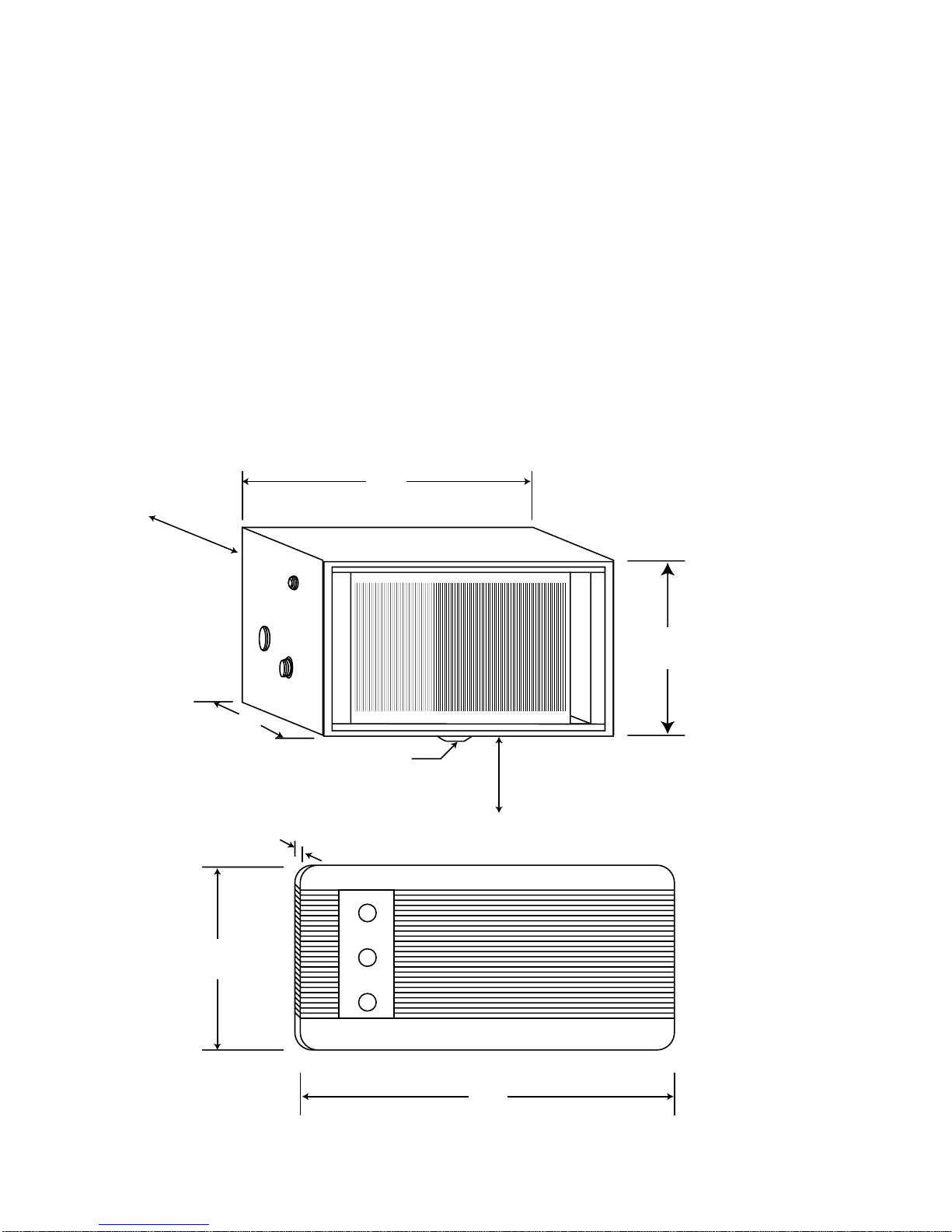
Figure 1
INSTALLATION INSTRUCTIONS FOR HERON 2.2
The Heron 2.2 is suitable for installation in most caravans & motorhomes.
Installation in Commercial and Industrial vehicles and equipment should be
referred to AIRCOMMAND AUST for assessment of suitability.
The capacity of the airconditioner to adequately cool or heat a van, is dependent on:
• The size of the van
• The thickness and quality of thermal insulation installed in the van
• The expected outside or ambient conditions.
The HERON 2.2 is recommended for vans up to 5.2 m overall, but assumes that
wall and ceilings are insulated with a minimum of 25 mm of insulation, wool or
foam. Windows should all have shades or curtains as a minimum.
If the van is to be used mainly in extreme conditions (40°C plus), then be
conservative, i.e. ensure the best insulation is installed, consider double glazed
windows, and size the airconditioner down to 4.8 m maximum.
315
440
460
235
Condenser
AIRHANDLER A/H
FACIA
2
DESCRIPTION OF THE HERON 2.2 SYSTEM
The HERON 2.2 is a split system, utilizing a condenser set (referred to throughout
this text as a CON/SET) and an airhandler (referred to as an A/H).
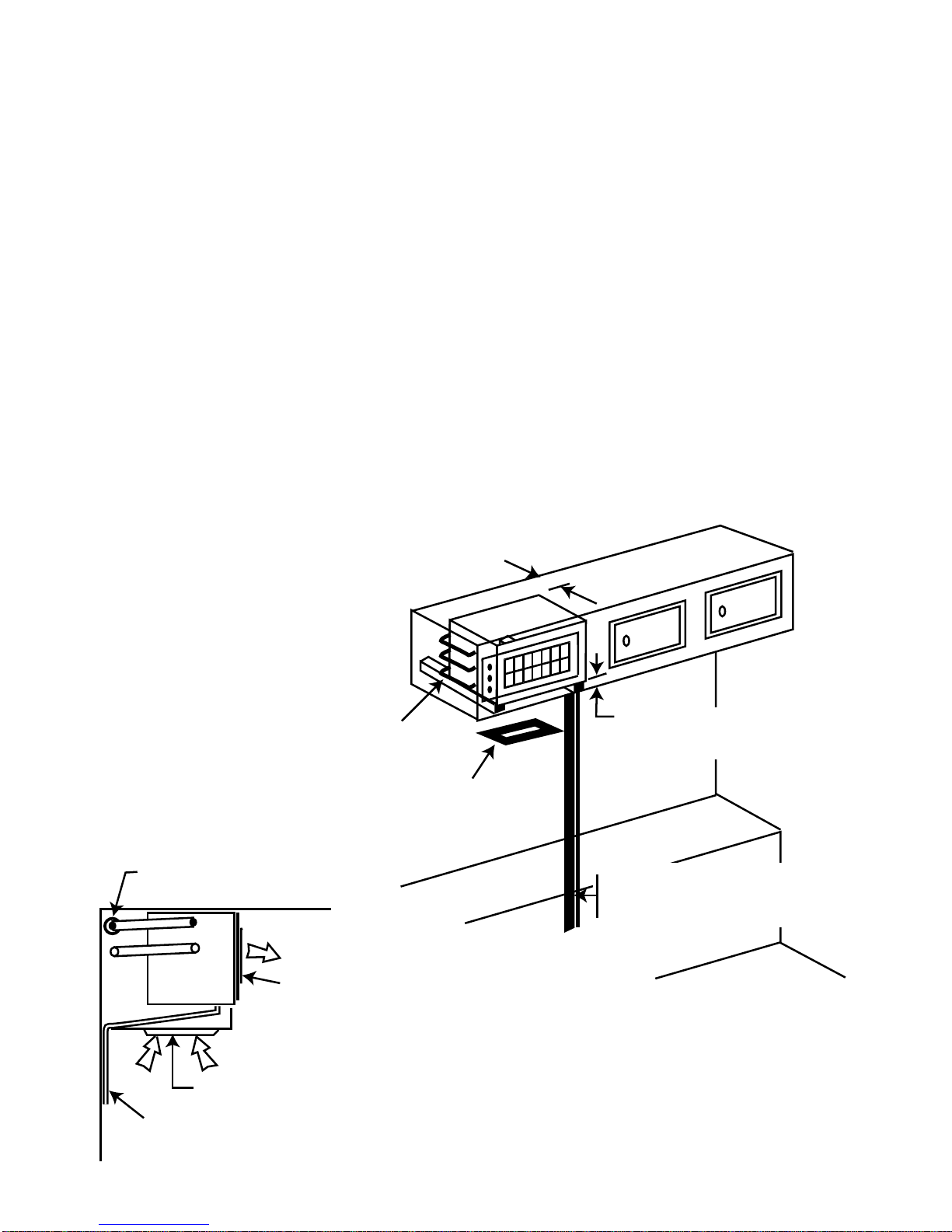
The Con/set is designed for installation beneath a bunk, settee, or in the bottom of
a floor cupboard. Refer fig. 1 for dimensions.
The A/H is designed for fitment into an overhead cupboard or similar, and comes
complete with facia and controls. See fig. 2.
The A/H and CON/SET are coupled by means of a pair of refrigerant lines, and a
control cable. The pipework is not supplied with the unit, but a standard 5 m
control cable is.
Before proceeding with the installation, consider a number of important details
that must be complied with in the following description.
220
380
DRAIN
RECOMMEND 70 MM TO FLOOR
OF CUPBOARD FOR ADAQUATE
"FALL" OF DRAIN
215
MUST ALLOW
90 MM SPACE
FOR AIR FLOW
TO FAN
270
12
490
Figure 2
3
Choosing a position for the con/set
Generally, avoid installation on the left hand side (annex side), as the condenser
set will discharge hot air into this space.
It is usual to install the con/set on the right hand side, either under a bunk, settee,
or at the bottom of a floor cupboard.
NOTE: Ensure that wherever the con/set is installed, reasonable access to the
top of the unit is always available, for service, and any shelving etc. above, must
be easily removed. Also, the two line valves on the back of the unit must be easily
accessed.
The maximum length of pipework between the Con/set and the A/H is 5 metres.
Installations exceeding this may require extra refrigerant to be added to the
system.
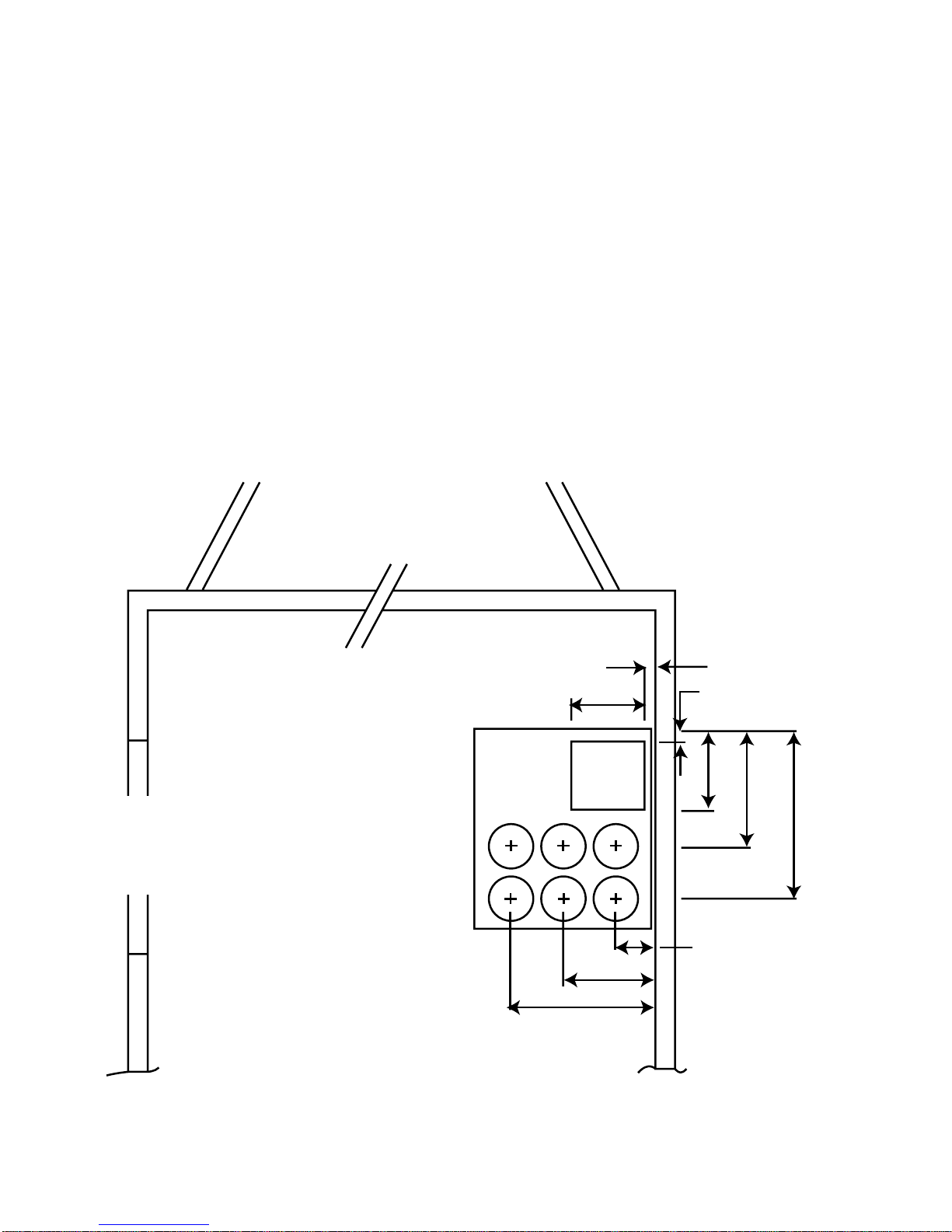
Figure 3
372
237
107
390
265
180
50
10
178
Comp.
well
Normally install condenser
set opposite to annexe
4
Installing the Condenser set
Marking out the floor
Use the floor template as provided (or refer to fig. 3). Both, or either end of the
con/set may be hard against a wall or panel, but the back of the unit must have
sufficient clearance to allow easy access to the line valves (see fig. 4). Once a
convenient position has been decided upon, place the template, side marked
“Inside Wall”, hard against the inside skin of the van, and mark out the six 114mm
diameter (4
1
/2”) condenser air inlet holes, and the square compressor well hole
(see fig. 3).
Note: Check to see if any structural floor members will interfere with any of these
holes. It is essential that the compressor well is unimpeded.
The air inlet holes will tolerate some obstruction. However the total area must not
be less than 75% of the inlet holes in the chassis.
We recommend that a hole saw be used to cut out the six round holes. If a
structural member is beneath, then the complete cut out can be removed. The gap
between the top of the structural member and the underside of the unit (i.e. the
floor thickness) will help in overcoming the restriction of the member.
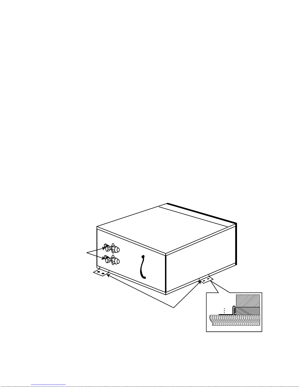
Clips
Line Valves
Figure 4
5
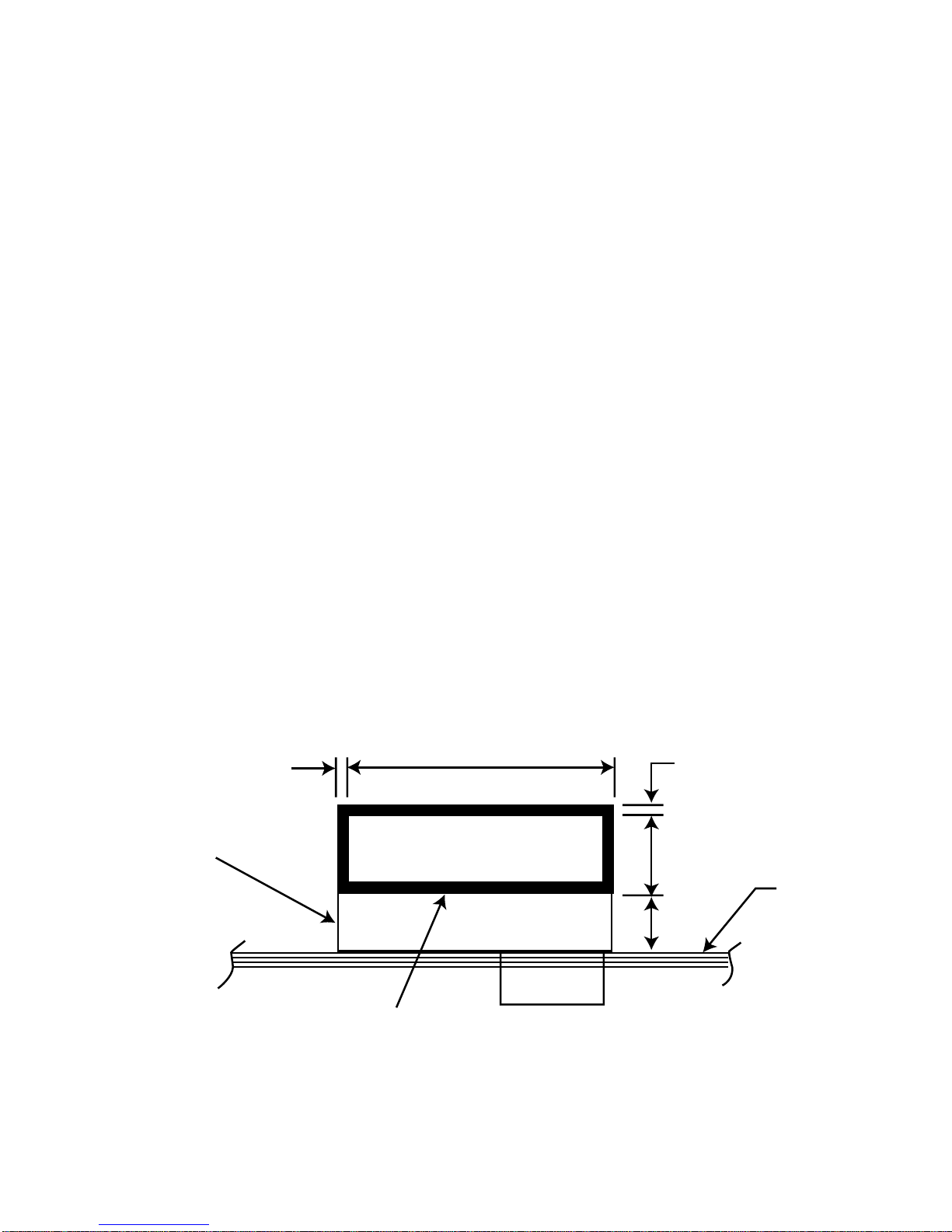
Marking out the wall
Now mark out the hole in the wall for the condenser discharge grille (see fig. 5).
Mark out the position and size of the air outlet hole, from inside the van, using the
floor as reference.
Witness holes can be drilled at the four corners, and the hole cut out from the
outside. It is essential to box up this hole to give a firm seal to the air outlet from
the con/set and to stop any discharge air from entering the wall space.
Positioning of the Con/set
Lay down a generous bead of silicone on the floor to match the perimeter of the
Con/set. Now, lift the Con/set into position, and check that the compressor well
does not interfere and prevent the chassis from sitting firmly on the floor.
Push the Con/set hard up against the wall.
It is vital that the Con/set seals hard against the inside wall to ensure no hot air
leakage during operation.
To secure the Con/set in position, use the two hold down clips provided (see fig. 4).
These clip over the edge of the chassis. At least one clip should be installed on the
back edge to ensure the good airseal is maintained against the inside wall.
Screw the clips firmly to the floor.
Condenser air outlet
Air handler
15
440
15
140
80
Floor
Figure 5
6
90 mm min.
75 mm between pan of unit and
bottom to allow for drain fall
Refrig. pipes cross
back of enclosure
and come round on
LH. side to give flexibility
2 return air filter
assy. inset to bottom
of cupboard
Refrig. lines, drain hose,
electrical cable
(cover with moulding)
Refrig. liner
Return air filter
Drain
Facia
Section Detail
Figure 6
PIPE INSTALLATION & CONTROL WIRING
The pipe work consists of a 1/4” tube (liquid line), and a 3/8” tube (return gas)
running between the Con/set and the A/H. The 3/8” line must be insulated with 10x
10 mm foam rubber insulation.
Connection is made at the back of the Con/set. Pipe work may be run internally to
the A/H, or may be run through holes in the floor and run externally to a
convenient re-entry point, or the pipes may be built into the wallspace during van
construction. N.B. Pipework installed in walls must be well insulated to avoid
“sweating” and possible long term moisture damage.
The control wiring will normally follow the pipework and be taped to it. N.B. If
the control cable is to be run externally, then it must be run in a suitable conduit.
Now refer to the A/H installation, after which we return to the Con/set to open up
the refrigeration circuit and fit the louvre panel.
7
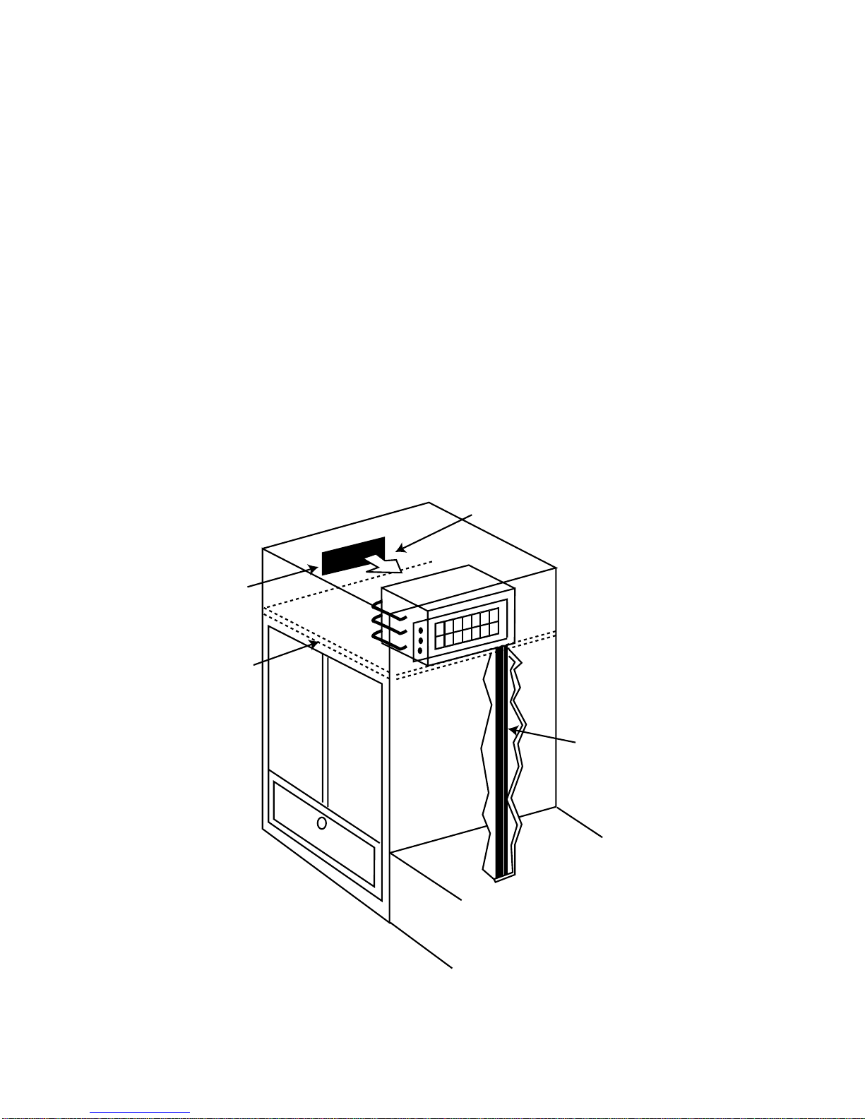
AIR HANDLER INSTALLATION
The A/H needs to be installed in as central as possible position, such that no short
cycling of discharge air will occur. See figs. 6 & 7.
3 most important points that must be satisfied
1. The distance from the back of the cupboard to the back of the A/H must not be
less than 90 mm to allow proper air entry to the fan.
2. Two separate return air grilles/filters are supplied, and must be installed. If
only one is used, this will reduce the air flow back to the fan.
3. The A/H has a condensate drain underneath. This drain must continuously
“fall” from the outlet. It is recommended that the bottom of the A/H be 70 mm
above the bottom of the cupboard, to allow adequate fall.
A lesser amount is ok, provided much care is exercised to avoid “humps” that will
result in airlocks and the backup & overflow of condensate.
Air flow
Refrig. pipes run through
floor and up rear of wardrobe
Return air
filter assy.
False ceiling
N.B. unit may sit hard on
ceiling as condensate drain
can be run vertically.
Figure 7
8
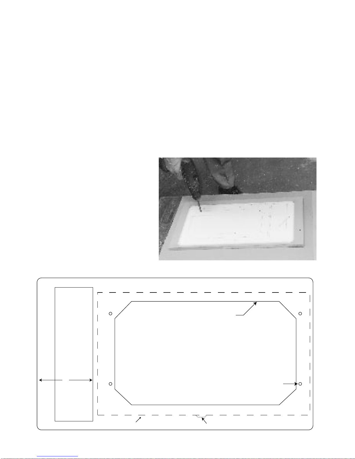
Refer to figs 8a & 8b and the full size template provided in the kit
The following describes the procedure for a cupboard with a full front that can be
removed. For cupboards that cannot be disassembled (retrofitting) see pp.5.
Set up the paper template on the front panel of cupboard and position it such that:
1. The facia panel will be centrally located on the cupboard if possible.
2. The connection side of the A/H needs to be a min of 110mm from the LHS wall
of the cupboard to allow the
3
/8 pipe to be bent around and flared (fig. 8a & 9).
3. The bottom of the A/H will be located so as to give sufficient fall for the drain.
Using adhesive tape stick down the template and drill pilot holes to mark the
cutouts. Also drill the 4 screw holes for the A/H retaining screws, & countersink
or counterbore so that the screw heads will be flush with the surface.
Figure 8b
Figure 8a
CUTTING TEMPLATE - AIR HANDLER
PART NO. 4002063
CUT OUT FOR AIR REGISTERS
DRILL 4 HOLES - 5 DIAMETER
OUTSIDE OF AIR HANDLER CABINET
CUT OUT FOR CONTROL BOX
MINIMUM 110 MM
TO SIDE WALL OF
CUPBOARD TO ALLOW
PIPEWORK TO BE
CONNECTED
DRAIN
 Loading...