

Page 1
Model HHC-90X/Model HC-5/15
SECTION 3. OPERATION
3-1. INTRODUCTION
3-2. OPERATING
CONTROLS AND
COMPONENTS
This section provides operating procedures for the heated holding
cabinets. The Introduction, Installation and Operation Sections
should be read, and all instructions should be followed before
operating the cabinet.
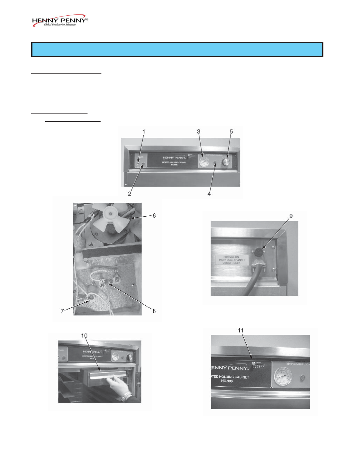
Figures 3-1 through 3-5 identify and describe the function of all
the operating controls and the major components of the cabinet.
Figure 3-1
Figure 3-3
Figure 3-2
Figure 3-4
203 3-1
Figure 3-5
Page 2

Model HHC-90X/Model HC-5/15
3-2. OPERATING CONTROLS AND COMPONENTS (Continued)
Fig. Item
No. No. Description Function
3-1 1 Power Switch A toggle switch that switches electrical current to the
unit
3-1 2 Power Light Illuminates when the power switch is in the ON
position and the components are energized
3-1 3 Thermometer Indicates the air temperature inside the cabinet
3-1 4 Heat Light Illuminates when the thermostat turns on the heaters
3-1 5 Thermostat An electromechanical device that controls the
temperature inside the cabinet
3-2 6 Blower Motor Used to recirculate the hot humid air throughout the
cabinet; there are two blower motor assemblies in the
cabinets
3-2 7 Heater Two, open-resistance, wire type heaters that provide
heat throughout the cabinet; a standard full sized 120
VAC unit will have 1000 watt heaters; a standard full
sized 240 VAC unit will have 1500 watt heaters;
a standard 120V, HHC-903 unit will have 750 watt
heaters
3-2 8 High Limit A safety device mounted next to the heater which
protects the unit from overheating
3-3 9 Fuse A protective device that breaks the circuit when
current exceeds the rated value; the fuse provides
an overload protection for the electrical components;
to remove the fuse, twist and pull the cap; the fuse is
used only on the 120V/2000 watt units
3-4 10 Water Pan Holds the water for creating humidity in the cabinet
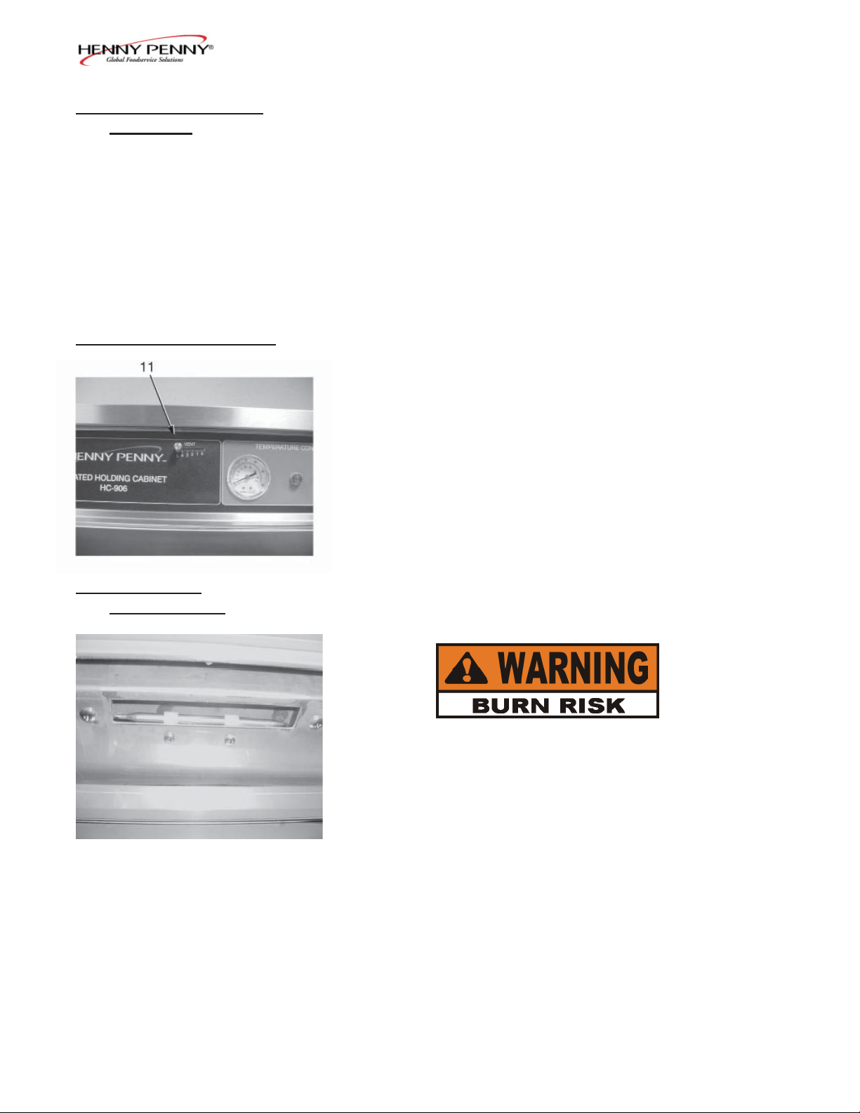
3-5 11 Venting System Controls the humidity levels in the cabinet
(Units with vent
adjustment only)
3-2 203
Page 3
3-3. START-UP
Model HHC-90X/Model HC-5/15
Before using the heated holding cabinet, the unit should be
thoroughly cleaned as described in the Cleaning Procedures
Section of this manual.
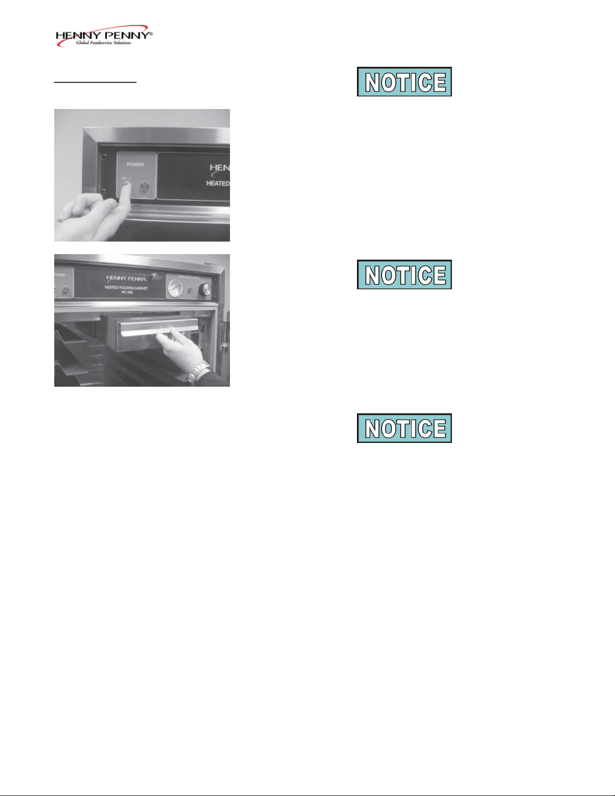
1. To put the unit into operation, move the power switch to the
ON position. The power light should now be illuminated and
the blowers should be in operation.
2. Remove the water pan and put approximately 1” of hot water
in the pan. Return the pan to its location.
Step 1
Be sure to push the water pan in as far as it will go so that it
does not block air from the thermometer and thermostat capillary tubes. This will ensure proper operation of these components.
Step 2
3. Set the thermostat at #7 or approximately 180°F (82°C).
When the heat light goes out, the unit is ready for operation.
The unit should take approximately 25-35 minutes to heat to
temperature during start up. Be sure that the temperature light
goes out before loading with product.
203 3-3
Page 4
Model HHC-90X/Model HC-5/15
3-4. OPERATION WITH
PRODUCT
3-5. VENT ADJUSTMENT
1. Place the hot product on bun pans and insert between the
cabinet racks.
2. Serve the product f rst that has been in the cabinet the
longest.
3. In order to maintain a constant temperature, open the doors
only as necessary to load and unload product.
As mentioned in the Operating Controls and Component Section,
the vent system limits the humidity level of the cabinet. The vent
adjustments are very easy to follow.
The vent setting corresponds to the number of trays of product.
With one tray of product, set the vent at No. 1. With two trays of
product, set the vent at No. 2 and so on.
3-6. CLEANING
PROCEDURES
Step 3
1. Turn all controls to the OFF position.
2. Disconnect the electrical supply to the cabinet.
To avoid burns, allow the unit to cool before cleaning.
3. Open the doors and remove all trays from the cabinet.
4. Take the trays to a sink and clean them thoroughly.
5. Remove the water pan and clean it with a soft cloth, soap,
and water.
3-4 203
Page 5
Model HHC-90X/Model HC-5/15
3-6. CLEANING
PROCEDURES
(Continued)
Step 6
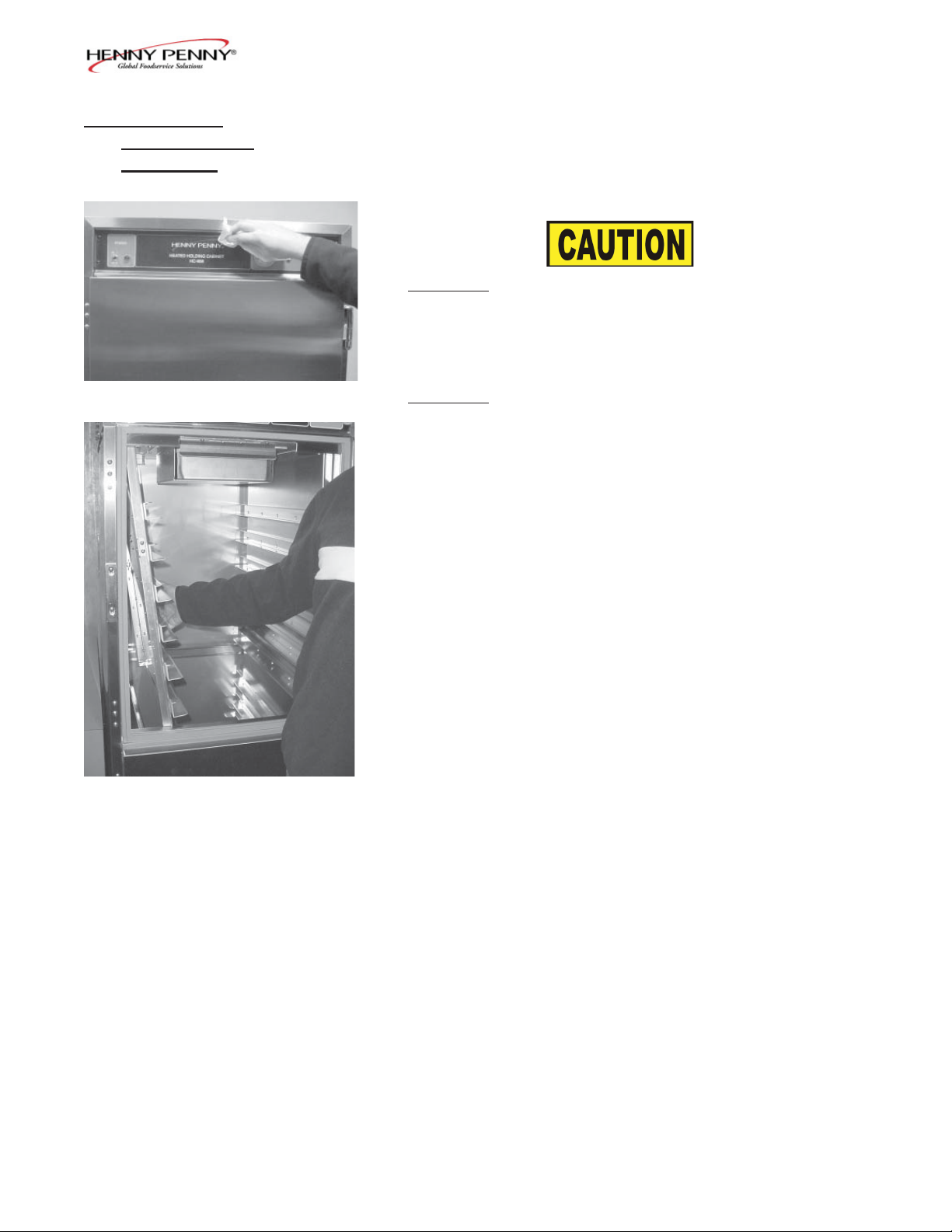
6. Wipe the control panel with a damp cloth. Do not splash
water around the controls.
7. Clean the exterior of the cabinet with a damp cloth.
Do not use steel wool, other abrasive cleaners or
cleaners/sanitizers containing chlorine, bromine, iodine
or ammonia chemicals, as these will deteriorate the
stainless steel material and shorten the life of the unit.
Do not use a water jet (pressure sprayer) to clean
the unit, or component failure could result.
8. Open the doors and remove side racks. Clean the racks with
soap and water.
Step 8
9. Clean the interior of the cabinet thoroughly with a cloth and
soap water.
10. Put the side racks and water pan back into the cabinet.
11. Leave at least one door open over night to allow the unit to
thoroughly dry out.
203 3-5
Page 6

Model HHC-90X/Model HC-5/15
3-7. OPERATING
CONTROLS COUNTDOWN TIMERS
(if applicable)
These instructions are for both 13 and 5 count down timers.
Start-Up
1. Turn the power switch to the ON position.
2. The display shows the increase in temperature, indicating
the unit is heating.
3. When the preset temperature is reached, the HEAT ON LED
turns off and the display stays at the preset temperature.
Temperature Regulation
1. Press and hold the PROGRAM button.
2. The control beeps and “Prog Enter Code” shows in display.
3. Enter access code 1, 2, 3.
4. Press the INCREASE or DECREASE buttons to change the
f ashing setpoint temperature.
5. Press and hold the PROGRAM button to set the temperature
and exit the programming mode.
Timer Operation
Each of the timers can be started, stopped, or cancelled, and not
affect the status of the other timers.
1. Press the desired timer button.
2. The time remaining shows in the display.
3. At end of time cycle, an alarm sounds and “0:00” is displayed.
4. Press the timer to stop alarm and “---” is displayed.
Press and hold an active timer to cancel.
3-6 203
Page 7

Model HHC-90X/Model HC-5/15
3-7. OPERATING
CONTROLS COUNTDOWN TIMERS
(if applicable)
(Continued)
Timer Regulation - All timers can be set to a different starting
time.
1. Press and hold the PROGRAM button.
2. The control beeps and “Prog Enter Code” shows in display.
3. Enter access code 1, 2, 3.
4. Press the PROGRAM button, and “---” is displayed, along
with all the timer settings.
5. Press the desired timer and the starting time f ashes.
6. Press the INCREASE and DECREASE buttons to change
the starting time.
7. Press the timer button to set the new starting time, and now
a different timer button can pressed, and it’s starting time
can be changed.
8. When f nished setting timers, press and hold the PROGRAM button to exit programming.
Exit the program mode at any time by pressing and holding
the PROGRAM button. Also, if no buttons are pressed for 2
minutes, programming is exited automatically.
Timing Through Power Down
If a power failure occurs while a timer is running, the timer resumes the countdown when power is restored.
203 3-7
Page 8

Model HHC-90X/Model HC-5/15
3-7. OPERATING
CONTROLS COUNTDOWN TIMERS
(if applicable)
(Continued)
Special Program Mode - Consists of Setup Mode and Tech
Mode.
Setup Mode
• Fahrenheit or Celsius
• Initialize System - One button programming for times and
temperatures
Fahrenheit or Celsius
1. Press and hold the PROGRAM button for 4 seconds.
2. “SetUP” and “Tech” are displayed.
3. Press a timer button under the word “SetUP”.
Ex: Setup
1 2 Press either 1 or 2.
4. Enter access code 1, 2, 3.
5. “SetUP deg. F” is displayed.
6. Press the INCREASE or DECREASE buttons to toggle from
“F” (Fahrenheit) and “C” (Celsius).
7. When correct setting displays, press the PROGRAM button
to move to initialize system, or press and hold the PROGRAM button to exit programming.
CE and international units must have the temperature readings in Celsius. Follow above procedures and set to “C”.
Initialize System
1. Press and hold the PROGRAM button for 4 seconds.
2. “SetUP” and “Tech” are displayed.
3-8 203
Page 9

Model HHC-90X/Model HC-5/15
3-7. OPERATING
CONTROLS COUNTDOWN TIMERS
(if applicable)
(Continued)
Initialize System (Continued)
3. Press a timer button under the word “SetUP”.
Ex: “SetUP”
1 2 Press either 1 or 2.
4. Enter access code 1, 2, 3.
5. “SetUP deg. F” is displayed.
6. Press PROGRAM button and “SetUP init sys” is displayed.
7. Press and hold either the INCREASE or DECREASE button.
8. The control beeps and the display counts down, 5, 4, 3, 2, 1,
0.
9. When display reaches “0”, release the button and the initialization is complete.
If the INCREASE or DECREASE button is released before “0”
is displayed, the control will not initialize.
10. Press the PROGRAM button to return to the Fahrenheit/Celsius mode, or press and hold the PROGRAM button to exit
programming.
Tech Mode
• Output test - heaters
• CPU calibration
• T emperature calibration
• Display tests
• Push-button test
• T otal initialization
The Tech Mode is mostly used at the factory level. The output tests and temperature probe calibration are given below.
For further information, call the Technical Services Department at Henny Penny, 1-800-417-8405, or 1-937-456-8405.
203 3-9
Page 10

Model HHC-90X/Model HC-5/15
(Continued)
3-7. OPERATING
CONTROLS COUNTDOWN TIMERS
(if applicable)
Output System
1. Press and hold the PROGRAM button for 4 seconds.
2. “SetUP” and “Tech” are displayed.
3. Press a timer button under the word “Tech”.
Ex: “Tech”
4 5 Press either 4 or 5.
4. Enter access code 1, 1, 2, 2, 1, 1, 2, 2.
5. “outP test Htr” is displayed.
6. Press the 5 timer button (under “Htr”) to turn heat and heat
LED on and off.
7. Press the PROGRAM button to move to the next step, or
press and hold the PROGRAM button to exit programming.
Temperature Calibration
1. Press and hold the PROGRAM button for 4 seconds.
2. “Setup” and “Tech” are displayed.
3. Press a timer button under the word “Tech”.
Ex: “Tech”
4 5 Press either 4 or 5.
4. Enter access code 1, 1, 2, 2, 1, 1, 2, 2.
5. “outP test Htr” is displayed.
6. Press the PROGRAM button 3 times until “CAL OFS Hi
Probe 185” is displayed.
7. Press and hold number 1 timer (under “CAL”), while pressing the INCREASE and DECREASE buttons and set the
display to match the actual cabinet temperature.
8. Press the PROGRAM button to move to the next step or
press and hold the PROGRAM button to exit programming.
3-10 203
Page 11

Model HHC-90X/Model HC-5/15
3-8. SIMPLEHOLD
CONTROLS
(if applicable)
Operation
1. Turn the power switch to the ON position and the actual tem perature shows in the display.
To check the setpoint temperature, press and hold .
2. Remove water pan and put about 1” (25.4 mm) of hot water
in pan. Return pan to cabinet.
Be sure to push the water pan in as far as it will go, so that
it does not block the air to the temperature probe, to ensure
an accurate temperature reading
3. Allow unit to heat 25 to 30 minutes to reach setpoint tem
perature, and the heat LED f ashes, before loading product
into cabinet.
Programming
To change the setpoint temperature, press and hold and
then use to set the desired setpoint temperature.
If the controls are locked the setpoint cannot be changed
until the controls are unlocked. See Special Programming
below .
To access the Special Program Mode:
With the Power Switch OFF, press and hold , and then turn
the power switch on.
1. “ºF” or “C”shows in the display. To toggle between
Fahrenheit and Celsius, press .
405 3-11
Page 12

Model HHC-90X/Model HC-5/15
3-8. SIMPLEHOLD
CONTROLS
(if applicable)
(Continued)
2. After entering the Special Program Mode, press once
and “int” shows in the display. Press and hold or
and the display counts down “In3-In2-In1”.
This reinitializes the controls and sets all controls to 0.
3. After entering the Special Program Mode, press and release
twice, and “Cal” shows in the display, followed by
the current probe temperature. The probe can be calibrated
+ 10º F, and can be changed by using .
4. After entering the Special Program Mode, press and release
three times, and “OP” shows in the display.
Use to toggle between “888” and a blank
display. “888” turns all heat outputs on, and a blank display
turns them off.
5. After entering the Special Program Mode, press and release
four times, and P=L, or P=U, shows in the display.
Use to toggle between L (lock), and U (unlock).
3-12 405
Page 13

Model HHC-90X/Model HC-5/15
3-9. FRONT & REAR OPERATING
CONTROLS-HHC-903-10 CDT
Front Controls
Rear Controls
Start-UP
1. Turn the power switch to the ON position.
2. The display shows the increase in temperature, indicating
the unit is heating.
Press and hold to view the setpoint temperature.
3. When the preset temperature is reached, the “HEAT ON”
LED turns off and display stays at the preset temperature.
Timer Operation
Each of the timers can be started, stopped, or cancelled, and not
affect the status of the other timers.
1. Press the desired timer button, from either the front or rear
of the unit.
2. The time remaining f ashes in both front and rear displays.
If #2 timer is started on the front, #2 timer also shows
timing down on the rear of the unit. If more than one
timer is running, the timer with the least amount of time
remaining f ashes.
3. At end of time cycle, alarm sounds and “0:00” displays.
4. Press the timer to stop alarm and “---” is displayed.
Press and hold an active timer to cancel.
Vent Adjustment
The vent adjustment on the rear panel limits the humidity level
inside the unit. Sliding the knob to a setting of 5 opens the two
vent holes completely and a setting of 0 closes them.
1106 3-13
Page 14

Model HHC-90X/Model HC-5/15
3-9. FRONT & REAR OPERATING
CONTROLS-HHC-903-10 CDT
(Continued)
Programming Temperature and Timers
1. Press and hold until “Prog” shows in the display
2. Press to change the f ashing setpoint temperature.
If “LOC” shows in the display at this time, the programming
controls are locked and must be unlocked. See Special
Program Mode Section.
3. Press and release to program the timers. Press any
of the timer buttons, on either side of the unit, and when
they are f ashing, use to set the timer in minutes
and seconds. If a timer is f ashing on one side of the unit,
the corresponding timer on the other side of the unit also
f ashes. For example, if timer #2 on the front of the unit
is f ashing, #2 on the rear of the unit also f ashes. So, both
front and rear timers are programmed at the same time.
More than one timer can be programmed at the same time
if they are to be programmed with identical times. Just
press the timers to be programmed and when they are all
f ashing, use to set the time in all timers. Again, both
front and reartimers will be programmed.
4. Press and hold to exit the Program Mode and all
settings are now programmed.
SPECIAL PROGRAM MODE
This mode consists of:
• Fahrenheit or Celsius Programming
• Initialize System - One button programming for times and
temperatures
• Probe Calibration
• Locking or Unlocking Programming
• Outputs Test
1. Turn power switch OFF and press and hold until
“SP” shows in the display, followed by the software version.
3-14 1106
Page 15

Model HHC-90X/Model HC-5/15
3-9. FRONT & REAR OPERATING
CONTROLS-HHC-903-10 CDT
(Continued)
2. Press when “oF” or “oC” shows in the display, use
to change the temperature reading from Fahrenheit
to Celsius, or vice-versa.
3. Press and release and “int” shows in the display.
4. Press and hold or and display counts down,
“in-3, in-2, in-1”. When “int SYS” shows in the display,
release the or and the initialization is complete.
The temperature and timers are now programmed to factory presets.
5. Press and release and “CAL” shows in the display,
followed by the probe temperature, inside the unit.
6. Use to set the displayed temperature to match the
actual temperature inside the unit.
7. Press and release twice and “P= L or U” shows in
the display. “P=L” means Locked and the setpoint
temperature and timers CANNOT be programmed. “P=U”
means Unlocked and the setpoint temperature and timers
CAN be programmed. Use the to toggle the display
from
“P=L” to “P=U” or vice-versa.
8. Press and release and “OP” shows in the display.
Use the to toggle the outputs ON & OFF. When the
outputs are ON, the HEAT ON LED should come on and
“8888” shows in the display, indicating the outputs are
working correctly.
9. Press and hold to exit Special Program Mode and
all modes will now be set.
1106 3-15
 Loading...